EP2403433B1 - Bone joining apparatus - Google Patents
Bone joining apparatusDownload PDFInfo
- Publication number
- EP2403433B1 EP2403433B1EP10744409.3AEP10744409AEP2403433B1EP 2403433 B1EP2403433 B1EP 2403433B1EP 10744409 AEP10744409 AEP 10744409AEP 2403433 B1EP2403433 B1EP 2403433B1
- Authority
- EP
- European Patent Office
- Prior art keywords
- connector
- ring
- cavity
- shaft
- knob
- Prior art date
- Legal status (The legal status is an assumption and is not a legal conclusion. Google has not performed a legal analysis and makes no representation as to the accuracy of the status listed.)
- Active
Links
Images


Classifications
- A—HUMAN NECESSITIES
- A61—MEDICAL OR VETERINARY SCIENCE; HYGIENE
- A61B—DIAGNOSIS; SURGERY; IDENTIFICATION
- A61B17/00—Surgical instruments, devices or methods
- A61B17/56—Surgical instruments or methods for treatment of bones or joints; Devices specially adapted therefor
- A61B17/58—Surgical instruments or methods for treatment of bones or joints; Devices specially adapted therefor for osteosynthesis, e.g. bone plates, screws or setting implements
- A61B17/68—Internal fixation devices, including fasteners and spinal fixators, even if a part thereof projects from the skin
- A61B17/84—Fasteners therefor or fasteners being internal fixation devices
- A61B17/86—Pins or screws or threaded wires; nuts therefor
- A61B17/8685—Pins or screws or threaded wires; nuts therefor comprising multiple separate parts
- A—HUMAN NECESSITIES
- A61—MEDICAL OR VETERINARY SCIENCE; HYGIENE
- A61B—DIAGNOSIS; SURGERY; IDENTIFICATION
- A61B17/00—Surgical instruments, devices or methods
- A61B17/56—Surgical instruments or methods for treatment of bones or joints; Devices specially adapted therefor
- A61B17/58—Surgical instruments or methods for treatment of bones or joints; Devices specially adapted therefor for osteosynthesis, e.g. bone plates, screws or setting implements
- A61B17/68—Internal fixation devices, including fasteners and spinal fixators, even if a part thereof projects from the skin
- A61B17/82—Internal fixation devices, including fasteners and spinal fixators, even if a part thereof projects from the skin for bone cerclage
- A—HUMAN NECESSITIES
- A61—MEDICAL OR VETERINARY SCIENCE; HYGIENE
- A61B—DIAGNOSIS; SURGERY; IDENTIFICATION
- A61B17/00—Surgical instruments, devices or methods
- A61B17/16—Instruments for performing osteoclasis; Drills or chisels for bones; Trepans
- A61B17/1662—Instruments for performing osteoclasis; Drills or chisels for bones; Trepans for particular parts of the body
- A61B17/1682—Instruments for performing osteoclasis; Drills or chisels for bones; Trepans for particular parts of the body for the foot or ankle
- A—HUMAN NECESSITIES
- A61—MEDICAL OR VETERINARY SCIENCE; HYGIENE
- A61B—DIAGNOSIS; SURGERY; IDENTIFICATION
- A61B17/00—Surgical instruments, devices or methods
- A61B17/56—Surgical instruments or methods for treatment of bones or joints; Devices specially adapted therefor
- A61B17/58—Surgical instruments or methods for treatment of bones or joints; Devices specially adapted therefor for osteosynthesis, e.g. bone plates, screws or setting implements
- A61B17/68—Internal fixation devices, including fasteners and spinal fixators, even if a part thereof projects from the skin
- A61B17/72—Intramedullary devices, e.g. pins or nails
- A61B17/7291—Intramedullary devices, e.g. pins or nails for small bones, e.g. in the foot, ankle, hand or wrist
- A—HUMAN NECESSITIES
- A61—MEDICAL OR VETERINARY SCIENCE; HYGIENE
- A61F—FILTERS IMPLANTABLE INTO BLOOD VESSELS; PROSTHESES; DEVICES PROVIDING PATENCY TO, OR PREVENTING COLLAPSING OF, TUBULAR STRUCTURES OF THE BODY, e.g. STENTS; ORTHOPAEDIC, NURSING OR CONTRACEPTIVE DEVICES; FOMENTATION; TREATMENT OR PROTECTION OF EYES OR EARS; BANDAGES, DRESSINGS OR ABSORBENT PADS; FIRST-AID KITS
- A61F2/00—Filters implantable into blood vessels; Prostheses, i.e. artificial substitutes or replacements for parts of the body; Appliances for connecting them with the body; Devices providing patency to, or preventing collapsing of, tubular structures of the body, e.g. stents
- A61F2/02—Prostheses implantable into the body
- A61F2/30—Joints
- A61F2/42—Joints for wrists or ankles; for hands, e.g. fingers; for feet, e.g. toes
- A61F2/4225—Joints for wrists or ankles; for hands, e.g. fingers; for feet, e.g. toes for feet, e.g. toes
- A—HUMAN NECESSITIES
- A61—MEDICAL OR VETERINARY SCIENCE; HYGIENE
- A61F—FILTERS IMPLANTABLE INTO BLOOD VESSELS; PROSTHESES; DEVICES PROVIDING PATENCY TO, OR PREVENTING COLLAPSING OF, TUBULAR STRUCTURES OF THE BODY, e.g. STENTS; ORTHOPAEDIC, NURSING OR CONTRACEPTIVE DEVICES; FOMENTATION; TREATMENT OR PROTECTION OF EYES OR EARS; BANDAGES, DRESSINGS OR ABSORBENT PADS; FIRST-AID KITS
- A61F2/00—Filters implantable into blood vessels; Prostheses, i.e. artificial substitutes or replacements for parts of the body; Appliances for connecting them with the body; Devices providing patency to, or preventing collapsing of, tubular structures of the body, e.g. stents
- A61F2/02—Prostheses implantable into the body
- A61F2/30—Joints
- A61F2/46—Special tools for implanting artificial joints
- A61F2/4603—Special tools for implanting artificial joints for insertion or extraction of endoprosthetic joints or of accessories thereof
- A61F2/4606—Special tools for implanting artificial joints for insertion or extraction of endoprosthetic joints or of accessories thereof of wrists or ankles; of hands, e.g. fingers; of feet, e.g. toes
- A—HUMAN NECESSITIES
- A61—MEDICAL OR VETERINARY SCIENCE; HYGIENE
- A61B—DIAGNOSIS; SURGERY; IDENTIFICATION
- A61B17/00—Surgical instruments, devices or methods
- A61B17/56—Surgical instruments or methods for treatment of bones or joints; Devices specially adapted therefor
- A61B17/58—Surgical instruments or methods for treatment of bones or joints; Devices specially adapted therefor for osteosynthesis, e.g. bone plates, screws or setting implements
- A61B17/68—Internal fixation devices, including fasteners and spinal fixators, even if a part thereof projects from the skin
- A61B17/84—Fasteners therefor or fasteners being internal fixation devices
- A61B17/86—Pins or screws or threaded wires; nuts therefor
- A—HUMAN NECESSITIES
- A61—MEDICAL OR VETERINARY SCIENCE; HYGIENE
- A61F—FILTERS IMPLANTABLE INTO BLOOD VESSELS; PROSTHESES; DEVICES PROVIDING PATENCY TO, OR PREVENTING COLLAPSING OF, TUBULAR STRUCTURES OF THE BODY, e.g. STENTS; ORTHOPAEDIC, NURSING OR CONTRACEPTIVE DEVICES; FOMENTATION; TREATMENT OR PROTECTION OF EYES OR EARS; BANDAGES, DRESSINGS OR ABSORBENT PADS; FIRST-AID KITS
- A61F2/00—Filters implantable into blood vessels; Prostheses, i.e. artificial substitutes or replacements for parts of the body; Appliances for connecting them with the body; Devices providing patency to, or preventing collapsing of, tubular structures of the body, e.g. stents
- A61F2/02—Prostheses implantable into the body
- A61F2/30—Joints
- A61F2002/30001—Additional features of subject-matter classified in A61F2/28, A61F2/30 and subgroups thereof
- A61F2002/30108—Shapes
- A61F2002/30199—Three-dimensional shapes
- A61F2002/30205—Three-dimensional shapes conical
- A—HUMAN NECESSITIES
- A61—MEDICAL OR VETERINARY SCIENCE; HYGIENE
- A61F—FILTERS IMPLANTABLE INTO BLOOD VESSELS; PROSTHESES; DEVICES PROVIDING PATENCY TO, OR PREVENTING COLLAPSING OF, TUBULAR STRUCTURES OF THE BODY, e.g. STENTS; ORTHOPAEDIC, NURSING OR CONTRACEPTIVE DEVICES; FOMENTATION; TREATMENT OR PROTECTION OF EYES OR EARS; BANDAGES, DRESSINGS OR ABSORBENT PADS; FIRST-AID KITS
- A61F2/00—Filters implantable into blood vessels; Prostheses, i.e. artificial substitutes or replacements for parts of the body; Appliances for connecting them with the body; Devices providing patency to, or preventing collapsing of, tubular structures of the body, e.g. stents
- A61F2/02—Prostheses implantable into the body
- A61F2/30—Joints
- A61F2002/30001—Additional features of subject-matter classified in A61F2/28, A61F2/30 and subgroups thereof
- A61F2002/30316—The prosthesis having different structural features at different locations within the same prosthesis; Connections between prosthetic parts; Special structural features of bone or joint prostheses not otherwise provided for
- A61F2002/30329—Connections or couplings between prosthetic parts, e.g. between modular parts; Connecting elements
- A61F2002/30331—Connections or couplings between prosthetic parts, e.g. between modular parts; Connecting elements made by longitudinally pushing a protrusion into a complementarily-shaped recess, e.g. held by friction fit
- A—HUMAN NECESSITIES
- A61—MEDICAL OR VETERINARY SCIENCE; HYGIENE
- A61F—FILTERS IMPLANTABLE INTO BLOOD VESSELS; PROSTHESES; DEVICES PROVIDING PATENCY TO, OR PREVENTING COLLAPSING OF, TUBULAR STRUCTURES OF THE BODY, e.g. STENTS; ORTHOPAEDIC, NURSING OR CONTRACEPTIVE DEVICES; FOMENTATION; TREATMENT OR PROTECTION OF EYES OR EARS; BANDAGES, DRESSINGS OR ABSORBENT PADS; FIRST-AID KITS
- A61F2/00—Filters implantable into blood vessels; Prostheses, i.e. artificial substitutes or replacements for parts of the body; Appliances for connecting them with the body; Devices providing patency to, or preventing collapsing of, tubular structures of the body, e.g. stents
- A61F2/02—Prostheses implantable into the body
- A61F2/30—Joints
- A61F2002/30001—Additional features of subject-matter classified in A61F2/28, A61F2/30 and subgroups thereof
- A61F2002/30316—The prosthesis having different structural features at different locations within the same prosthesis; Connections between prosthetic parts; Special structural features of bone or joint prostheses not otherwise provided for
- A61F2002/30329—Connections or couplings between prosthetic parts, e.g. between modular parts; Connecting elements
- A61F2002/30476—Connections or couplings between prosthetic parts, e.g. between modular parts; Connecting elements locked by an additional locking mechanism
- A61F2002/30481—Connections or couplings between prosthetic parts, e.g. between modular parts; Connecting elements locked by an additional locking mechanism using a locking clip
- A—HUMAN NECESSITIES
- A61—MEDICAL OR VETERINARY SCIENCE; HYGIENE
- A61F—FILTERS IMPLANTABLE INTO BLOOD VESSELS; PROSTHESES; DEVICES PROVIDING PATENCY TO, OR PREVENTING COLLAPSING OF, TUBULAR STRUCTURES OF THE BODY, e.g. STENTS; ORTHOPAEDIC, NURSING OR CONTRACEPTIVE DEVICES; FOMENTATION; TREATMENT OR PROTECTION OF EYES OR EARS; BANDAGES, DRESSINGS OR ABSORBENT PADS; FIRST-AID KITS
- A61F2/00—Filters implantable into blood vessels; Prostheses, i.e. artificial substitutes or replacements for parts of the body; Appliances for connecting them with the body; Devices providing patency to, or preventing collapsing of, tubular structures of the body, e.g. stents
- A61F2/02—Prostheses implantable into the body
- A61F2/30—Joints
- A61F2002/30001—Additional features of subject-matter classified in A61F2/28, A61F2/30 and subgroups thereof
- A61F2002/30316—The prosthesis having different structural features at different locations within the same prosthesis; Connections between prosthetic parts; Special structural features of bone or joint prostheses not otherwise provided for
- A61F2002/30329—Connections or couplings between prosthetic parts, e.g. between modular parts; Connecting elements
- A61F2002/30476—Connections or couplings between prosthetic parts, e.g. between modular parts; Connecting elements locked by an additional locking mechanism
- A61F2002/30487—Circumferential cooperating grooves and beads on cooperating lateral surfaces of a mainly longitudinal connection
- A—HUMAN NECESSITIES
- A61—MEDICAL OR VETERINARY SCIENCE; HYGIENE
- A61F—FILTERS IMPLANTABLE INTO BLOOD VESSELS; PROSTHESES; DEVICES PROVIDING PATENCY TO, OR PREVENTING COLLAPSING OF, TUBULAR STRUCTURES OF THE BODY, e.g. STENTS; ORTHOPAEDIC, NURSING OR CONTRACEPTIVE DEVICES; FOMENTATION; TREATMENT OR PROTECTION OF EYES OR EARS; BANDAGES, DRESSINGS OR ABSORBENT PADS; FIRST-AID KITS
- A61F2/00—Filters implantable into blood vessels; Prostheses, i.e. artificial substitutes or replacements for parts of the body; Appliances for connecting them with the body; Devices providing patency to, or preventing collapsing of, tubular structures of the body, e.g. stents
- A61F2/02—Prostheses implantable into the body
- A61F2/30—Joints
- A61F2002/30001—Additional features of subject-matter classified in A61F2/28, A61F2/30 and subgroups thereof
- A61F2002/30316—The prosthesis having different structural features at different locations within the same prosthesis; Connections between prosthetic parts; Special structural features of bone or joint prostheses not otherwise provided for
- A61F2002/30329—Connections or couplings between prosthetic parts, e.g. between modular parts; Connecting elements
- A61F2002/30476—Connections or couplings between prosthetic parts, e.g. between modular parts; Connecting elements locked by an additional locking mechanism
- A61F2002/30495—Connections or couplings between prosthetic parts, e.g. between modular parts; Connecting elements locked by an additional locking mechanism using a locking ring
- A—HUMAN NECESSITIES
- A61—MEDICAL OR VETERINARY SCIENCE; HYGIENE
- A61F—FILTERS IMPLANTABLE INTO BLOOD VESSELS; PROSTHESES; DEVICES PROVIDING PATENCY TO, OR PREVENTING COLLAPSING OF, TUBULAR STRUCTURES OF THE BODY, e.g. STENTS; ORTHOPAEDIC, NURSING OR CONTRACEPTIVE DEVICES; FOMENTATION; TREATMENT OR PROTECTION OF EYES OR EARS; BANDAGES, DRESSINGS OR ABSORBENT PADS; FIRST-AID KITS
- A61F2/00—Filters implantable into blood vessels; Prostheses, i.e. artificial substitutes or replacements for parts of the body; Appliances for connecting them with the body; Devices providing patency to, or preventing collapsing of, tubular structures of the body, e.g. stents
- A61F2/02—Prostheses implantable into the body
- A61F2/30—Joints
- A61F2002/30001—Additional features of subject-matter classified in A61F2/28, A61F2/30 and subgroups thereof
- A61F2002/30316—The prosthesis having different structural features at different locations within the same prosthesis; Connections between prosthetic parts; Special structural features of bone or joint prostheses not otherwise provided for
- A61F2002/30535—Special structural features of bone or joint prostheses not otherwise provided for
- A61F2002/30537—Special structural features of bone or joint prostheses not otherwise provided for adjustable
- A61F2002/30538—Special structural features of bone or joint prostheses not otherwise provided for adjustable for adjusting angular orientation
- A—HUMAN NECESSITIES
- A61—MEDICAL OR VETERINARY SCIENCE; HYGIENE
- A61F—FILTERS IMPLANTABLE INTO BLOOD VESSELS; PROSTHESES; DEVICES PROVIDING PATENCY TO, OR PREVENTING COLLAPSING OF, TUBULAR STRUCTURES OF THE BODY, e.g. STENTS; ORTHOPAEDIC, NURSING OR CONTRACEPTIVE DEVICES; FOMENTATION; TREATMENT OR PROTECTION OF EYES OR EARS; BANDAGES, DRESSINGS OR ABSORBENT PADS; FIRST-AID KITS
- A61F2/00—Filters implantable into blood vessels; Prostheses, i.e. artificial substitutes or replacements for parts of the body; Appliances for connecting them with the body; Devices providing patency to, or preventing collapsing of, tubular structures of the body, e.g. stents
- A61F2/02—Prostheses implantable into the body
- A61F2/30—Joints
- A61F2002/30001—Additional features of subject-matter classified in A61F2/28, A61F2/30 and subgroups thereof
- A61F2002/30316—The prosthesis having different structural features at different locations within the same prosthesis; Connections between prosthetic parts; Special structural features of bone or joint prostheses not otherwise provided for
- A61F2002/30535—Special structural features of bone or joint prostheses not otherwise provided for
- A61F2002/30537—Special structural features of bone or joint prostheses not otherwise provided for adjustable
- A61F2002/3055—Special structural features of bone or joint prostheses not otherwise provided for adjustable for adjusting length
- A—HUMAN NECESSITIES
- A61—MEDICAL OR VETERINARY SCIENCE; HYGIENE
- A61F—FILTERS IMPLANTABLE INTO BLOOD VESSELS; PROSTHESES; DEVICES PROVIDING PATENCY TO, OR PREVENTING COLLAPSING OF, TUBULAR STRUCTURES OF THE BODY, e.g. STENTS; ORTHOPAEDIC, NURSING OR CONTRACEPTIVE DEVICES; FOMENTATION; TREATMENT OR PROTECTION OF EYES OR EARS; BANDAGES, DRESSINGS OR ABSORBENT PADS; FIRST-AID KITS
- A61F2/00—Filters implantable into blood vessels; Prostheses, i.e. artificial substitutes or replacements for parts of the body; Appliances for connecting them with the body; Devices providing patency to, or preventing collapsing of, tubular structures of the body, e.g. stents
- A61F2/02—Prostheses implantable into the body
- A61F2/30—Joints
- A61F2002/30001—Additional features of subject-matter classified in A61F2/28, A61F2/30 and subgroups thereof
- A61F2002/30621—Features concerning the anatomical functioning or articulation of the prosthetic joint
- A61F2002/30622—Implant for fusing a joint or bone material
- A—HUMAN NECESSITIES
- A61—MEDICAL OR VETERINARY SCIENCE; HYGIENE
- A61F—FILTERS IMPLANTABLE INTO BLOOD VESSELS; PROSTHESES; DEVICES PROVIDING PATENCY TO, OR PREVENTING COLLAPSING OF, TUBULAR STRUCTURES OF THE BODY, e.g. STENTS; ORTHOPAEDIC, NURSING OR CONTRACEPTIVE DEVICES; FOMENTATION; TREATMENT OR PROTECTION OF EYES OR EARS; BANDAGES, DRESSINGS OR ABSORBENT PADS; FIRST-AID KITS
- A61F2/00—Filters implantable into blood vessels; Prostheses, i.e. artificial substitutes or replacements for parts of the body; Appliances for connecting them with the body; Devices providing patency to, or preventing collapsing of, tubular structures of the body, e.g. stents
- A61F2/02—Prostheses implantable into the body
- A61F2/30—Joints
- A61F2002/30001—Additional features of subject-matter classified in A61F2/28, A61F2/30 and subgroups thereof
- A61F2002/30621—Features concerning the anatomical functioning or articulation of the prosthetic joint
- A61F2002/30624—Hinged joint, e.g. with transverse axle restricting the movement
- A—HUMAN NECESSITIES
- A61—MEDICAL OR VETERINARY SCIENCE; HYGIENE
- A61F—FILTERS IMPLANTABLE INTO BLOOD VESSELS; PROSTHESES; DEVICES PROVIDING PATENCY TO, OR PREVENTING COLLAPSING OF, TUBULAR STRUCTURES OF THE BODY, e.g. STENTS; ORTHOPAEDIC, NURSING OR CONTRACEPTIVE DEVICES; FOMENTATION; TREATMENT OR PROTECTION OF EYES OR EARS; BANDAGES, DRESSINGS OR ABSORBENT PADS; FIRST-AID KITS
- A61F2/00—Filters implantable into blood vessels; Prostheses, i.e. artificial substitutes or replacements for parts of the body; Appliances for connecting them with the body; Devices providing patency to, or preventing collapsing of, tubular structures of the body, e.g. stents
- A61F2/02—Prostheses implantable into the body
- A61F2/30—Joints
- A61F2/30767—Special external or bone-contacting surface, e.g. coating for improving bone ingrowth
- A61F2/30771—Special external or bone-contacting surface, e.g. coating for improving bone ingrowth applied in original prostheses, e.g. holes or grooves
- A61F2002/3085—Special external or bone-contacting surface, e.g. coating for improving bone ingrowth applied in original prostheses, e.g. holes or grooves with a threaded, e.g. self-tapping, bone-engaging surface, e.g. external surface
- A61F2002/30873—Threadings machined on non-cylindrical external surfaces
- A—HUMAN NECESSITIES
- A61—MEDICAL OR VETERINARY SCIENCE; HYGIENE
- A61F—FILTERS IMPLANTABLE INTO BLOOD VESSELS; PROSTHESES; DEVICES PROVIDING PATENCY TO, OR PREVENTING COLLAPSING OF, TUBULAR STRUCTURES OF THE BODY, e.g. STENTS; ORTHOPAEDIC, NURSING OR CONTRACEPTIVE DEVICES; FOMENTATION; TREATMENT OR PROTECTION OF EYES OR EARS; BANDAGES, DRESSINGS OR ABSORBENT PADS; FIRST-AID KITS
- A61F2/00—Filters implantable into blood vessels; Prostheses, i.e. artificial substitutes or replacements for parts of the body; Appliances for connecting them with the body; Devices providing patency to, or preventing collapsing of, tubular structures of the body, e.g. stents
- A61F2/02—Prostheses implantable into the body
- A61F2/30—Joints
- A61F2/42—Joints for wrists or ankles; for hands, e.g. fingers; for feet, e.g. toes
- A61F2/4225—Joints for wrists or ankles; for hands, e.g. fingers; for feet, e.g. toes for feet, e.g. toes
- A61F2002/4228—Joints for wrists or ankles; for hands, e.g. fingers; for feet, e.g. toes for feet, e.g. toes for interphalangeal joints, i.e. IP joints
- A—HUMAN NECESSITIES
- A61—MEDICAL OR VETERINARY SCIENCE; HYGIENE
- A61F—FILTERS IMPLANTABLE INTO BLOOD VESSELS; PROSTHESES; DEVICES PROVIDING PATENCY TO, OR PREVENTING COLLAPSING OF, TUBULAR STRUCTURES OF THE BODY, e.g. STENTS; ORTHOPAEDIC, NURSING OR CONTRACEPTIVE DEVICES; FOMENTATION; TREATMENT OR PROTECTION OF EYES OR EARS; BANDAGES, DRESSINGS OR ABSORBENT PADS; FIRST-AID KITS
- A61F2/00—Filters implantable into blood vessels; Prostheses, i.e. artificial substitutes or replacements for parts of the body; Appliances for connecting them with the body; Devices providing patency to, or preventing collapsing of, tubular structures of the body, e.g. stents
- A61F2/02—Prostheses implantable into the body
- A61F2/30—Joints
- A61F2/42—Joints for wrists or ankles; for hands, e.g. fingers; for feet, e.g. toes
- A61F2/4225—Joints for wrists or ankles; for hands, e.g. fingers; for feet, e.g. toes for feet, e.g. toes
- A61F2002/4233—Joints for wrists or ankles; for hands, e.g. fingers; for feet, e.g. toes for feet, e.g. toes for metatarso-phalangeal joints, i.e. MTP joints
- A—HUMAN NECESSITIES
- A61—MEDICAL OR VETERINARY SCIENCE; HYGIENE
- A61F—FILTERS IMPLANTABLE INTO BLOOD VESSELS; PROSTHESES; DEVICES PROVIDING PATENCY TO, OR PREVENTING COLLAPSING OF, TUBULAR STRUCTURES OF THE BODY, e.g. STENTS; ORTHOPAEDIC, NURSING OR CONTRACEPTIVE DEVICES; FOMENTATION; TREATMENT OR PROTECTION OF EYES OR EARS; BANDAGES, DRESSINGS OR ABSORBENT PADS; FIRST-AID KITS
- A61F2220/00—Fixations or connections for prostheses classified in groups A61F2/00 - A61F2/26 or A61F2/82 or A61F9/00 or A61F11/00 or subgroups thereof
- A61F2220/0025—Connections or couplings between prosthetic parts, e.g. between modular parts; Connecting elements
- A61F2220/0033—Connections or couplings between prosthetic parts, e.g. between modular parts; Connecting elements made by longitudinally pushing a protrusion into a complementary-shaped recess, e.g. held by friction fit
- A—HUMAN NECESSITIES
- A61—MEDICAL OR VETERINARY SCIENCE; HYGIENE
- A61F—FILTERS IMPLANTABLE INTO BLOOD VESSELS; PROSTHESES; DEVICES PROVIDING PATENCY TO, OR PREVENTING COLLAPSING OF, TUBULAR STRUCTURES OF THE BODY, e.g. STENTS; ORTHOPAEDIC, NURSING OR CONTRACEPTIVE DEVICES; FOMENTATION; TREATMENT OR PROTECTION OF EYES OR EARS; BANDAGES, DRESSINGS OR ABSORBENT PADS; FIRST-AID KITS
- A61F2230/00—Geometry of prostheses classified in groups A61F2/00 - A61F2/26 or A61F2/82 or A61F9/00 or A61F11/00 or subgroups thereof
- A61F2230/0063—Three-dimensional shapes
- A61F2230/0067—Three-dimensional shapes conical
- A—HUMAN NECESSITIES
- A61—MEDICAL OR VETERINARY SCIENCE; HYGIENE
- A61F—FILTERS IMPLANTABLE INTO BLOOD VESSELS; PROSTHESES; DEVICES PROVIDING PATENCY TO, OR PREVENTING COLLAPSING OF, TUBULAR STRUCTURES OF THE BODY, e.g. STENTS; ORTHOPAEDIC, NURSING OR CONTRACEPTIVE DEVICES; FOMENTATION; TREATMENT OR PROTECTION OF EYES OR EARS; BANDAGES, DRESSINGS OR ABSORBENT PADS; FIRST-AID KITS
- A61F2250/00—Special features of prostheses classified in groups A61F2/00 - A61F2/26 or A61F2/82 or A61F9/00 or A61F11/00 or subgroups thereof
- A61F2250/0004—Special features of prostheses classified in groups A61F2/00 - A61F2/26 or A61F2/82 or A61F9/00 or A61F11/00 or subgroups thereof adjustable
- A61F2250/0006—Special features of prostheses classified in groups A61F2/00 - A61F2/26 or A61F2/82 or A61F9/00 or A61F11/00 or subgroups thereof adjustable for adjusting angular orientation
Definitions
- This applicationrelates to devices and methods for joining bones.
- Hammertoe deformitythe most common deformity of the lesser toes, is a flexion deformity of the Proximal interphalangeal (PIP) joint of the toe, with hyperextension of the metatarsophalangeal (MTP) and distal interphalangeal (DIP) joints.
- PIPProximal interphalangeal
- MTPmetatarsophalangeal
- DIPdistal interphalangeal
- Progressive PIP joint flexion deformitytypically leads to compensatory hyperextension of the MTP and DIP joints. This makes the PIP joint prominent dorsally. Pain occurs due to rubbing of the prominence against the patient's shoe.
- the deformityis flexible at first but usually becomes fixed over time. When the deformity is flexible, various procedures can be utilized that involve manipulation of the involved tendons. However, when the deformity is fixed, PIP fusion or joint replacement is often required.
- Implants available for this purposeinclude the Weil-CarverTM Hammertoe Implant (Biomet®, Inc., Warsaw, IN), Flexible Digital Implant (Tomier, Inc. Edina, MN), SHIP Implant (Sgarlato Labs, Campbell CA), Digital Compression Screw (BioPro®, Port Huron MI), Smart ToeTM Intramedullary Memory Implant (Memometal Inc., Memphis TN) and StayFuseTM Intramedullary Fusion Device (Tornier, Inc. Edina, MN).
- the latter three implantsare used when fusion is desired, since the other implants allow some flexibility of the joint. With all current implants, placement is critical because, when mounted, there is no adjustability in the angle of flexion between the two cut bones to be joined.
- Document US 6,458,134discloses a bone connector system comprising first and second connector members, which does not allow the flexion between said two bones.
- Document EP 1 632 200discloses a bone joining device suitable for joining together a first and a second bone pieces. More specifically, the bone joining device comprises two shaft parts, a receptor part with a spherical cup and a ball joint for insertion in the receptor part.
- Document US 5,417, 692discloses a bone fixation and fusion system which does not control the rotation from one member to the other one.
- a bone joining deviceis provided that allows adjustment of the angle between the two bones to be joined.
- a bone joining device suitable for joining a first bone piece to a second bone piececomprises a first component and a second component, wherein the first component comprises a first elongated stem portion comprising a first end and a first top opposite the first end, the first elongated stem portion suitable for insertion from the first end longitudinally into a surface of the first bone piece, and the second component comprises a second elongated stem portion comprising a second end and a second top, the second elongated stem portion suitable for insertion from the second end longitudinally into a surface of the second bone piece, and a connector extending from the second top, wherein the connector is capable of coupling with the first component and locking therewith, wherein the first elongated stem portion of the first component includes an opening comprising a cavity comprising a wall, a closed distal end and an open proximal end, and the connector is elongated and fits
- the connectoris angularly set with respect to the second top.
- the deviceis made from (a) titanium, (b) an alloy of titanium with about 6% aluminum and about 4% vanadium, (c) nitinol, (d) stainless steel, or (e) poly ethyl ethyl ketone (PEEK).
- the connectorcan be separated from the first component after insertion by rotating the connector in relation to the first component causing the at least one knob to slide out of the indentation or gap between two ridges of the connector, and onto a portion of the shaft that does not comprise an indentation or ridges, and then sliding the connector out of the first component while maintaining the at least one knob along the portion of the shaft that does not comprise an indentation or ridges.
- the knobbed c-ring or o-ringis a c-ring with two ends and a middle, comprising a knob in the middle of the c-ring such that the knob encounters a plurality of axially deposed indentations or gaps on one portion of the shaft when the connector is inserted into the cavity.
- the knobbed c-ringcomprises two knobs, such that each knob encounters a plurality of axially deposed indentations or gaps on two portions of the shaft when the connector is inserted into the cavity.
- the knobbed c-ring or o-ringis a c-ring with two ends and a middle, and the two knobs are between the middle and the ends of the c-ring.
- the shaft of the connectorcomprises a plurality of axially deposed indentations or gaps on two portions of the shaft and the knobbed c-ring or o-ring is a c-ring with two ends, comprising one knob at each end of the c-ring, such that each knob encounters a plurality of axially deposed indentations or gaps on two portions of the shaft when the connector is inserted into the cavity.
- the cylindrical shaftcomprises axially deposed indentations or ridges on two opposing sides of the shaft.
- the devicecomprises three indentations or four ridges on each of the two opposing sides of the cylindrical shaft.
- each of the axially deposed indentations or ridgescomprises a distal edge that is substantially perpendicular to the wall of the cavity.
- each of the axially deposed indentationscomprises a distal edge that forms an acute angle with the shaft of the connector.
- the inventorshave developed a bone joining device that allows adjustment of the angle between the two bones to be joined.
- the applicationis directed to a bone joining device suitable for joining a first bone piece to a second bone piece.
- the devicecomprises a first component and a second component, wherein the first component comprises a first elongated stem portion comprising a first end and a first top opposite the first end, the first elongated stem portion suitable for insertion from the first end longitudinally into a surface of the first bone piece, and the second component comprises a second elongated stem portion comprising a second end and a second top, the second elongated stem portion suitable for insertion from the second end longitudinally into a surface of the second bone piece.
- the devicefurther comprises a connector extending from the second top. The connector is capable of joining with the first component and locking therewith.
- the connectormay join with the first component by any means known in the art.
- joining meansinclude knobs, clamps, teeth, glues, Velcro® and staples.
- the first componentis a female component and the second component is a male component, wherein the first elongated stem portion of the female component further comprises an opening that extends axially from the first top toward the first end; and the connector comprises an elongated shaft, a proximal end, a top of shaft near the proximal end, and a distal end, wherein the connector is capable of insertion into the opening in the first elongated stem portion and locking therein.
- the figuresprovide several examples of these devices, as detailed below.
- the deviceis generally useful for joining any two bone pieces, for example two vertebrae or two halves of a broken bone.
- the deviceis particularly useful for joining or fusing cut surfaces of bones, in particular the cut ends of long bones, especially fingers or toes, e.g., for joining or fusing a joint on a lesser toe, for example to treat hammertoe, claw toe, mallet toe or curly toe.
- the first stem portionis suitable for insertion from the first end longitudinally into a cut surface of a resected phalanx, metatarsal or metacarpal, or a cut diaphysis
- the second stem portionis suitable for insertion from the second end longitudinally into a cut surface of a resected phalanx, metatarsal or metacarpal, or a cut diaphysis.
- the devicecan also be used to fuse a metatarsal that has been shortened by resection.
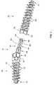
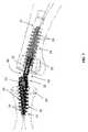
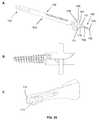
- FIGS. 1-33Various, nonlimiting embodiments of the device are shown in FIGS. 1-33 , where the bone joining device 10 is provided as a female component 20 and a male component 30.
- the female component 20 of this embodimentis an elongated stem, and comprises a first end 21, a first top 22 and a cylindrical cavity 29, best shown in FIGS. 2 , 13 , 14 and 22 , comprising a cylindrical wall 23, a closed distal end 27 and an open proximal end 28.
- the illustrated female component 20also comprises a continuous spiraling thread 24 on the exterior of the component, suitable for screwing the component into a bone.
- the female component 20is also referred to herein as the "first elongated stem portion.”
- the cavity and wallcan have any shape cross section as defined by the cavity wall, including, for example, circular, oval, rectangular hexagonal and octagonal.
- the male component 30,best shown in FIGS. 1 , 2 , 4 , 7 , 10 , 11 , 12 , 15 , 18 and 23 , comprises a second elongated stem portion 37 comprising a second end 31 and a second top 32, with a connector 40 extending from the second top 32.
- the male component 30is also referred to herein as the "second elongated stem portion.”
- the illustrated second elongated stem portion 37comprises a continuous spiraling thread 34 on the exterior, where the thread is suitable for screwing the component into a bone 50.
- the female component 20 and the male component 30can independently be cylindrical or conical, or any combination thereof, e.g. , cylindrical at the proximal end, transitioning into a conical shape.
- any alternate anchoring meanscan be used, for example barbs, a shape memory expanding means (e.g. , as featured in the Smart ToeTM Implant (Memometal Inc., Memphis TN), or any other anchoring means known in the art.
- the spiraling threads on the devicecan be of any type known in the art for screwing into a bone.
- the spiraling threadis a continuous spiraling thread.
- the spiraling threadallows self-tapping and/or self-threading of the first elongated stem portion into the first bone piece and the second elongated stem portion into the second bone piece. See, e.g., 240 of FIGS. 15-17 .
- the continuous spiraling thread 24 and 34 on the female and male componentsboth spiral in the same direction, e.g., clockwise, so that, when the device is screwed into opposing bone surfaces and then joined, the opposing pitch of the threads in the bone prevents the device from unscrewing.
- the pitchmay be 5 mm or greater, 4 mm, 3 mm, 2 mm, 1 mm, less than 1 mm, or any distance in between these distances.
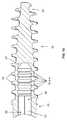
- the connector 40is as shown in FIGS. 1 , 11 and 12 .
- the connector 40extends from the second top 32 and comprises a proximal end 41, a top of shaft 46 near the proximal end 41, and a distal end 42.
- the proximal end 41comprises a connector hole 47, best shown in FIG. 12 , that is joined to the second top 32 in a recess 35 with crimping pins 33 and a crimping shaft 36.
- the connector 40When so joined, the connector 40 can be adjustably positioned in an angular direction in relation to the second top 32 until the crimping pins 33 are crimped toward each other along the crimping shaft 36, forcing outer flanges 36a outward, which engage the connector hole 47, causing friction between the outer flanges 36a and the connector hole 47 and preventing further adjustable positioning of the connector 40 in relation to the second top 32.
- the connector hole 47 in combination with the crimping shaft 36serves as a locking mechanism that prevents adjustable positioning of the connector 40 in relation to the second top.
- the distal end 42 of the connector 40is inserted into the open proximal end 28 of the female component 20, penetrating the cylindrical cavity 29 to a certain point, e.g., as in FIG. 3-7 and 16 .
- This partial insertion featureallows the connector 40 to then be adjusted to the desired angle in relation to the second top 32 before the device is inserted to its final position.
- the crimping pins 33are then crimped, using any tool that can push the two crimping pins 33 simultaneously into the crimping shaft 36, preventing further angular movement in relation to the second top.
- the connector 40is then further inserted into the shaft to the desired final position.
- FIG. 19An alternative embodiment to a crimping shaft to prevent positioning of a connector 40 in relation to a second top 32 is illustrated in FIG. 19 .
- the crimping shaftis substituted with a locking pin 360 that has a tapered cylindrical shape having a narrow end 362 and a wide end 364.
- the endscan be of any appropriate configuration, in the illustrated embodiment, both the narrow end 362 and the wide end 364 have inwardly directed indentations 366, 368, which is designed to accommodate a tool used to push the locking pin 360 into the connector hole 47.
- the locking pin 360is inserted partly into the connector hole 47 from the narrow end 362, where it acts as an hinge that connects the proximal end 41 of the connector 40 with the second top 32 of the second elongated stem portion 37, allowing angular positioning of the connector 40 in relation to the second top 32.
- the wide end 364 of the locking pin 360is pushed further into the connector hole 47, causing friction between the wide end 364 of the locking pin 360, the connector hole 47, and the second top 32 of the second elongated stem portion 37, frictionally preventing further movement of the connector 40 in relation to the second top 32.
- the locking pin 360can be pushed into the connector hole 47 using any suitable tool, for example a modified tissue clamp, a modified k-wire pliers, or the pin locking tool 60 illustrated in FIG. 20 .
- the pin locking tool 60comprises a handle 62 comprising a thumb hole and finger hole 63, 64 pivotally joined by a scissor hinge 65 to bring together distal ends 66, 67 when the thumb hole and finger hole 63, 64 are pulled together.
- Distal end 66is terminated by a contoured formation 68, which is configured to engage the second top 32.
- Distal end 68is terminated by a pin formation 69, which is configured to engage the wide end 364 of the locking pin 360.
- FIG. 20shows the engagement of the locking pin 360 before the connector 40 is joined to the female component 20
- the locking pin 360can also be so engaged after the connector 40 is so joined, e.g., after the connector 40 is partially inserted into the female component 20, as illustrated in FIGS. 3-7 .
- the pin locking tool 60can be used with the crimping pins 33 and a crimping shaft 36 described above and illustrated in FIG. 12 , or with any other suitable component.
- the angle of the connector 40is not locked in relation to the second top 32, e.g., when fixation is not desired, allowing flexion between the bone pieces such that the connector 40 - second top 32 forms a joint, for example a PIP, a DIP or an MTP joint.
- the locking pin 360 or crimping pin 33/crimping shaft 36is not pushed into the connector hole 47, or is only pushed in part way, to allow the desired degree of flexion.
- a simple pin or any other componentcan be inserted into the connector hole rather than the locking pin 360 or crimping pin 33/crimping shaft 36, to provide a hinge for the joint.
- the connector hole 47 and/or crimping shaft 36can be designed so that the connector 40 is limited in angular movement in relation to the second top 32.
- the connector 40is capable of being adjustably positioned at an angle of at least 10° in each of a forward direction and a reverse direction in relation to the second top 32.
- the connector 40is capable of being adjustably positioned at an angle of at least 90° in each of a forward direction and a reverse direction in relation to the second top 32. See FIG. 6 .
- the connector 40is capable of being adjustably positioned at an angle of at least 120° in each of a forward direction and a reverse direction in relation to the second top 32.
- the connector 40is capable of being adjustably positioned at an angle of at least 150° in each of a forward direction and a reverse direction in relation to the second top 32.
- the connector 40is coupled to the second top 32 using a snap-lock, where the connector 40 can lock in the first elongated stem portion 20 without further insertion of the connector 40 into the first elongated stem portion 32.
- the cylindrical cavity 29 of the female component 20is designed to receive the connector 40 through the proximal end 28 of the cavity 29 ( FIG. 13 and 14 ).
- the connector 40is elongated and cylindrical.
- the connectorfurther comprises a ring 44 formed around the distal end 42, where the ring 44 has a diameter larger than the diameter of the cylindrical cavity 23 and cross slits 43 directed axially from the distal end 42 toward the proximal end 41 of the connector 40, thereby forming a spring collet 45 (shown in FIGS. 1 , 2 , 4 , 9 , 11 and 12 ).
- the cylindrical cavity 29further comprises at least a first ring-shaped recess 25a circumscribing the cylindrical wall 23 near the distal end such that, when the connector 40 is inserted into the cylindrical cavity 29, the spring collet 45 is compressed until the ring 44 encounters the first recess 25a, where the first recess 25a accommodates a less compressed diameter of the ring 44 and the spring collet 45 transitions to a less compressed state.
- FIGS. 3-7show the illustrated embodiment at that position.
- the ring 44can comprise an edge 48 on the side closer to the proximal end 41 of the connector 40, where the edge is designed to prevent movement of the connector 40 in the proximal direction after encountering the ring-shaped recess 25a.
- the edge 48is substantially perpendicular to the wall 23 of the cylindrical cavity 29. In other embodiments, the edge 48 forms an acute angle with the perimeter of the connector 40.
- the wall 23 of the cylindrical cavity 29further comprises a second ring-shaped recess 25b circumscribing the cylindrical wall 23 closer to the distal end 27 than the first recess 25a, where the connector 40 can be inserted beyond the first recess 25a, compressing the spring collet 45 until the ring 44 encounters the second recess 25b, where the second recess 25b accommodates a less compressed diameter of the ring 44 and the spring collet 45 transitions to a less compressed state.
- the distance between the recesses 25a and 25b in the wall 23 of the cylindrical cavity 29can be any distance appropriate for the particular application.
- the distancemay be 5 mm or greater, 4 mm, 3 mm, 2 mm, 1 mm, less than 1 mm, or any distance in between these values.
- the distanceis anywhere from 0.2 mm to 1 mm, for example about 0.6 mm.
- the wall 23 of the cylindrical cavity 29further comprises a third ring-shaped recess 25c circumscribing the cylindrical wall 23 closer to the distal end 27 than the second recess 25b, where the connector 40 can be inserted beyond the second recess 25b, compressing the spring collet 45 until the ring 44 encounters the third recess 25c, where the third recess 25c accommodates a less compressed diameter of the ring 44 and the spring collet 45 transitions to a less compressed state.
- the wall 23 of the cylindrical cavity 29additionally comprises a fourth and fifth ring-shaped recess 25d and 25e circumscribing the cylindrical wall 23 closer to the distal end 27 than the third recess 25c, where the connector 40 can be inserted beyond the third recess 25c, compressing the spring collet 45 until the ring 44 encounters the fourth recess 25d or fifth recess 25e, where the fourth and fifth recess 25d and 25e accommodates a less compressed diameter of the ring 44 and the spring collet 45 transitions to a less compressed state.
- FIGS. 8-10show the illustrated embodiment in that position.
- FIGS. 3 , 4 and 6illustrate that when the spring collet 45 is engaged in the first recess 25a, there is a gap between the second top 32 and the first top 22, such that the top of the shaft 46 of the connector 40 is exposed.
- the gapprovides room for the second top to adjustably position the second elongated stem portion 37 to any angle desired.
- FIG. 7illustrates the device in a digit, showing the gap between the second top 32 and the first top 22.
- the deviceprovides continuous adjustability of the male component 30 in relation to the connector 40 in the flexion of the joint.
- the jointcan be flexed to any degree necessary. If fusion is desired, that fusion can be made at the desired angle of flexion.
- those two componentsshould rotationally align with each other so that the top of the shaft 46 can fit inside the proximal end of the cylindrical cavity 29.
- the positioning of the connector 40 in an angular directionshould be made in the proper rotational plane, such that the connector 40 can be positioned along an angle that follows the natural flexion of the digit.
- the identity of the proper alignment of the female and male componentscan be accomplished by any means, for example by providing marks on the first top 22 and near the proximal end 41 of the connector 40, where the marks align at the desired position of the male component 30 and female component 20 when the ring 44 is in the first recess 25a. Additionally, when the ring 44 is in the first recess 25a, the connector 40 may be adjusted to the desired angle in relation to the second top 32 and the crimping pins 33 crimped, preventing further angular movement of the connector 40 in relation to the second top 32.
- the devicemay additionally comprise any means to prevent rotation of the connector 40 in relation to the first elongated stem portion 20, and to assure that the male component 30 and female component 20 are properly aligned rotationally.
- the connector 40comprises a groove 401 along the length of the connector
- the first elongated stem portion 20further comprises a pin hole 231 through the side of the first elongated stem portion 20, the pin hole 231 further comprising an anti-rotation pin 201 capable of fitting in the groove 401 of the connector 40 when the connector 40 is inserted into the proximal end of the cavity 29 of the first elongated stem portion 20.
- the anti-rotation pin 201prevents rotation of the connector 40 in relation to the first elongated stem portion 20 when the anti-rotation pin is in the groove 401 of the connector 40.
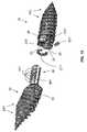
- the connector 40further comprises at least two shaft-rings 441 surrounding and protruding from the shaft.
- Each shaft ring 441varies from the other shaft-ring(s) in their proximity to the distal end of the shaft.
- the circumference of the shaft-rings 441is slightly less than the circumference of the cylindrical cavity 29 in the first elongated stem portion 20 of the female component.
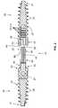
- Six shaft ringsare in the device shown in FIGS. 15-17 , and three in the device shown in FIG. 18 .
- the cylindrical cavity 29 in the first elongated stem portion of the female componentfurther comprises a slot 221 circumscribing the cylindrical wall 23 near the proximal end 28 of the cavity 29.
- the slot 221further comprises a c-ring 211 fitting therein.
- the c-ring 211protrudes into the cavity 29 when relaxed.
- the c-ring 221expands and recedes into the slot 221 when the connector 40 is inserted into the cavity 29 and a shaft-ring 441 encounters the c-ring 221 and pushes against it. This allows the shaft ring 441 to pass the c-ring 221.
- the shaft ring 441passes the c-ring 221, providing space in the cavity 29 to accommodate the relaxed c-ring, the c-ring 221 becomes relaxed again and contracts, re-protruding into the cavity 29.
- the connector 40is manually rotationally adjusted in relation to the male component 30 to the final desired position (e.g., the desired angle of flexion of a joint being fused, or a properly aligned position of the two parts of a broken bone or vertebral fusion).
- the crimping pin 33is then crimped, to prevent further rotational movement.
- the connector 40may then inserted the rest of the was into the cavity 29, as in FIG. 17 , aligning the two bone pieces. It is noted that, in FIG. 17 , all six shaft rings 441 have passed the c-ring 221. In the alternate design illustrated in FIG. 18 , there are three shaft rings 441.
- the top of the shaft 46 of the connector 40comprises a hexagonal formation 49 and the first top 22 comprises a hexagonal recess 26, where the hexagonal formation 49 fits into the hexagonal recess 26 when the connector 40 is inserted into the cylindrical cavity 29.
- the formation and recesscan be circular, pentagonal, square or any other shape.
- the first top 22is concave and the second top 32 is convex, as shown, e.g., in FIG. 5 , such that, when screwed into the bones, the first top 22 and the second top 32 match common osteotomy cuts where one bone is cut in a concave shape and the other bone is cut in a convex shape.
- At least one of the hexagonal recess 26 and the hexagonal formation 49is smoothed where the connector 40 first encounters the hexagonal recess 26 such that the hexagonal formation 49 will fit into the hexagonal recess 46 even if the marks are not fully aligned at the desired position.
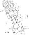
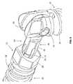
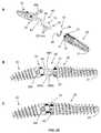
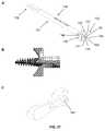
- FIGS. 21-23An alternative configuration of the bone fixation device is illustrated in FIGS. 21-23 .
- the connector 40 of this configurationcomprises a proximal end 41 having a connector hole 47, a top of shaft 46 near the proximal end 41, and a distal end 42.
- the shaft 70 of the connector 40is cylindrical, with a plurality (here, three) of axially deposed indentations 250a-c, 252a-c on at least one side of the shaft 70.
- the connector 40may be elongate but not cylindrical, e.g.
- the cylindrical shaft 70 of the connector 40comprises a second set of three axially deposed indentations 250a-c, 252a-c on opposing sides of the shaft.
- the female component 20 of this embodimentis an elongated stem, comprising a first end 21, a first top 22, an open proximal end 28 and a cylindrical cavity 29.
- the cylindrical cavity 29comprises a cylindrical wall 23, a closed distal end 27 and an open proximal end 28.
- the illustrated female component 20also comprises a spiraling thread 24 on the exterior of the component, suitable for screwing the component into a bone.
- the female component 20also comprises an indentation 72 at least partially circumscribing the first top 22, with at least one (here, two) hole 74, 76 passing through the first top 22 into the cylindrical cavity 29.
- the female component 20additionally comprises a knobbed c-ring 80, comprising at least one (here, two) knob protruding inward 82, 84.
- the knobbed c-ring 80is configured to fit into the indentation 72 in the first top 22 of the female component 20, such that the knobs fit into the holes 74, 76 and protrude into the cylindrical cavity 29.
- the connector 40is joined to the male component 30 at the connector hole 47 by inserting the narrow end 362 of the locking pin 360 (as illustrated in FIG. 23 ) or the crimping shaft 36 and crimping pins 33 (as illustrated in FIG. 12 ) through the hole on one side of the second top 32 and into the connector hole 47.
- the shaft 70 of the connector 40is inserted into the open proximal end 28 and into the cylindrical cavity 29 of the female component 20, where the distal end 42 of the shaft 70 encounters the knobs 82, 84 of the knobbed c-ring 80, which are protruding into the cylindrical cavity 29.
- the distal end 42 of the shaft 70pushes on the knobs 82, 84, expanding the knobbed c-ring 80 such that the knobs 82, 84 are pushed out of the cylindrical cavity 29 to accommodate the shaft 70, until the knobs 82, 84 encounter the first indentations 250c,f, allowing the knobs to move back into the cylindrical cavity 29 in the space created by the indentations, such that the knobbed c-ring 80 compresses back to its original shape.
- the indentations 250can comprise an edge 480 on the side closer to the distal end 42 of the connector 40, where the edge is designed to prevent movement of the connector 40 in the proximal direction after encountering the indentation 250.
- the edge 480is substantially perpendicular to the wall 23 of the cylindrical cavity 29. In other embodiments, the edge 480 forms an acute angle with the perimeter of the shaft 70.
- the knobbed c-ring 80again expands as the area between the first indentations 250c,f and the second indentations 250b,e pushes the knobs 82, 84 out of the cylindrical cavity 29, until the knobs 82, 84 encounter the second indentations 250b,e. This continues until the knobs 82, 84 are at the indentations most proximal to the male component 30, when the device is seated in its final position.
- the desired angle of flexion between the connector 40 and the male component 30is made and set by, e.g., fully engaging the locking pin 360 using the pin locking tool 60, or crimping the crimping pins 33 into the crimping shaft 36 ( FIG. 12 ), as appropriate.
- the knobbed c-ringcan instead be an o-ring, and/or can comprise one, or any number of knobs in conjunction with a matching number of aligning sets of axially deposed indentations.
- the knob or knobscan be deposed anywhere along the c-ring, e.g., in the middle of the c-ring, on one or both ends, or between the middle and one or both end.
- the knobbed c-ring or o-ringcan be utilized in conjunction with the connectors described in any of FIGS. 16-18 , or any similar connector, instead of the c-ring 211 and anti-rotation pin 201 described previously.
- the presence of the knob in the cavity or the gap between ridgeshas the advantage of limiting the rotation of the connector in the cavity or the gap between ridges, since the presence of the knob in the cavity or the gap between ridges limits any rotation to the width of the indention or the gap between ridges, unless additional force is applied in rotating the connector to force the knob(s) out of the indentation or the gap between ridges, as described in the following paragraph.
- the connector 40can be separated from the female component 20 by rotating the connector 40 in relation to the female component 20 (which can be achieved after implantation by rotating one bone piece in relation to the other). This causes the knobs 82, 84 to slide out of the indentation or the gap between ridges (e.g., 250a and 250d if fully implanted) and onto the portion of the shaft 70 between the opposing indentations or the gap between ridges (e.g., 250a and 250d). The connector 40 can then slide out of the female component 20 along that portion of the shaft 70.
- the presence of the knob in the indentation or the gap between ridgessubstantially limits the rotation of the connector in the cavity.
- rotating the connector in relation to the cavityis a means for disconnecting the male and female components of the device.
- the shape and composition of the indentation or the gap between ridges, the c-ring or o-ring, and the knob(s)can be designed to have a balance between the ease with which the male and female components can be disconnected and the force required to overcome the ability of the knob in the cavity to prevent rotation of the connector in relation to the cavity.
- the indentation or the gap between ridgeswith, e.g ., silicone or Teflon to reduce the friction between the knob and the side of the indentation or the gap between ridges, or smoothing or angling the edge of the indentation or the gap between ridges where the knob encounters the wall of the indentation or the gap between ridges when the connector is rotated, makes separation of the male and female components easier and also makes it easier for the connector to be rotated to overcome the resistance to rotation caused by the presence of the knob in the indentation or the gap between ridges.
- silicone or Teflonto reduce the friction between the knob and the side of the indentation or the gap between ridges, or smoothing or angling the edge of the indentation or the gap between ridges where the knob encounters the wall of the indentation or the gap between ridges when the connector is rotated
- knobsare relatively long and also makes rotating the connector to overcome the resistance to rotation more difficult.
- the number and location(s) of the knob(s)also affect the ease with which rotating the connector to overcome the resistance to rotation can be achieved. For example, using a c-ring with only one knob (corresponding to only one set of axially deposed indentations or gaps between ridges) makes such rotation easier than using a c-ring with two knobs (corresponding to two sets of indentations or gaps between ridges).
- deposing the knobs on the end of the c-ringmakes overcoming the resistance to rotation easier than deposing the knobs toward the middle of the c-ring, since the c-ring requires greater bending distance and force when the knobs are deposed toward the middle in order for them to be pushed out of the cylindrical cavity.
- the use of a c-ring made of a more flexible materialmakes overcoming the resistance to rotation easier then using a c-ring made of a less flexible material.
- the devices described hereincan be of any diameter appropriate for the particular bones being joined, as defined by the widest diameter of the spiraling thread 24, 34 of the female component 20 or the male component 30.
- the diameter of either componentis more than 5 mm. In other embodiments, the diameter of either component is about 5 mm, about 4 mm, about 3 mm, about 2 mm, about 1 mm, less than 1 mm, or any diameter in between, for example about 2.2 mm.
- the bone fixation devicecan be fabricated from any appropriate material.
- the deviceis not bioabsorbable, since it is anticipated that the device provides stability to the fusion site. Additionally, should the two bones joined by the device fail to fuse, the device would provide essential structural support to keep the two bones together.
- Nonlimiting examples of materials that could be used to fabricate the deviceinclude (a) titanium, (b) an alloy of titanium with about 6% aluminum and about 4% vanadium, (c) nitinol, (d) stainless steel, and (e) a polymer such as poly ethyl ethyl ketone (PEEK).
- This applicationis also directed to a method of joining a first bone piece with a second bone piece in a living vertebrate.
- the methodcomprises inserting the above-described bone fixation device between the first bone piece and the second bone piece such that the two bone pieces are securely joined.
- the methodcan be used on any vertebrate species.
- the vertebrateis a mammal, for example a human.
- the methodcomprises preparing the two bone pieces to provide a cut surface on each piece that will be joined to each other; inserting the first elongated stem portion longitudinally into the cut surface of the first bone piece such that the first end is inserted first and the first top is at or slightly below the cut surface of the first bone piece; inserting the second elongated stem portion longitudinally into the cut surface of the second bone piece such that the proximal end of the connector is just above the cut surface of the second bone piece; and inserting the connector into the opening in the first elongated stem portion.
- the connectoris coupled to the second top at the proximal end by a coupling allowing the adjustable positioning of the connector in an angular direction in relation to the second top.
- the methodfurther comprises adjusting the position of the connector in relation to the second top to form a preferred angle of flexion between the two bone pieces; and further inserting the connector into the first elongated stem portion.
- the position of the connector in relation to the second topcan no longer be adjusted after the connector is further inserted into the first elongated stem portion. As previously described, this can be accomplished by providing a crimping pin mechanism, as provided in the illustrated embodiments.
- the bone piecesare (a) two adjoining phalanges; (b) a phalanx and an adjoining metacarpal; (c) a phalanx and an adjoining metatarsal; or (d) bone pieces separated by a fracture or osteotomy of a bone diaphysis.
- these bonescan be in the hand or the foot.
- the bone piecesare in the foot of the mammal.
- the footcan have any condition for which the treatment involves a bone joining two bone pieces. Examples of such conditions include hammertoe, mallet toe, curly toe, or claw toe.
- the interphalangeal, metatarsophalangeal or metacarpophalangeal jointis fused.
- the bone piecesare separated by an osteotomy that shortens the bone, for example a lesser metatarsal.
- An example of such a procedure that can utilize the instant methodis a Weil osteotomy, which shortens a metatarsal to provide an improved metatarsal parabola.
- the two bone piecesare from a single metatarsal bone that is subjected to an osteotomy of the diaphysis.
- the first boneis cut in a convex shape and the second bone is cut in a concave shape.
- These embodimentsare particularly accommodated when the first top 22 of the device is concave and the second top 32 is convex, as shown, e.g., in FIG. 5 .
- these methodscan further comprise procedures wherein the first bone piece and the second bone piece are cut; the bone fixation device 10 is inserted between the first bone piece 50 and the second bone piece 50; the connector 40 is inserted into the cylindrical cavity 29 to the first recess 25a before locking the connector 40, where the connector is locked by crimping the crimping pins 33.
- FIG. 7shows the device of the illustrated embodiment after this step.
- the connector 40is further inserted into the cylindrical cavity 29 at least to the second recess 25b, until the cut surface on the first bone piece and the second bone piece are joined together.
- FIG. 10shows the device of the illustrated embodiment after this step.
- the devicecan further comprise marks on the first top 22 and near the proximal end 41 of the connector 40, the marks aligning at the desired position of the male component 30 and female component 20 when the connector 40 is inserted into the first elongated stem portion ( i.e., the female component) 20.
- the first elongated stem portion 20is inserted into the cut surface of the first bone piece 50 by screwing the first elongated stem portion 20 longitudinally into the cut surface of the first bone piece 50
- the second elongated stem portion 37is inserted into the cut surface of the second bone piece 50 by screwing the second elongated stem portion 37 longitudinally into the cut surface of the second bone piece, where the mark on the first top 22 and the mark near the proximal end 41 of the connector 40 are adjacent to each other after insertion of the second elongated stem portion 37.
- the proximal end 41 of the connector 40comprises a hexagonal formation 49 and the first top 22 comprises a hexagonal recess 26, wherein the hexagonal formation 49 fits into the hexagonal recess 26 when the connector 41 is inserted into the first stem portion 20, where at least one of the hexagonal formation 49 and hexagonal recess 26 is smoothed where the hexagonal formation 49 first encounters the hexagonal recess 26 such that the hexagonal formation 49 will fit into the hexagonal recess 26 even if the marks are not fully aligned at the desired position; and the cut surface of the first bone comprises a notch to accommodate the hexagonal formation 49.
- the interphalangeal jointis exposed and the distal end of the proximal phalanx and the proximal end of the middle phalanx are cut off perpendicular to the long axis of each bone. This creates about a 3mm gap between the bones.
- a pilot holeis then drilled, e.g ., about 18 mm deep, in the proximal phalanx through the intramedullary canal.
- the pilot holecan be drilled using any appropriate pilot drill known in the art.
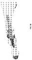
- the pilot holeis drilled with a tool designed especially for the device described above, for example the pilot drill 90 shown in FIG. 24 .
- a drillcomprises an elongate shank 91 having a proximal end 92 and a distal end 93.
- the proximal endcan comprise a handle or can be configured to join to a separate handle, for example the quick connect handle 160 illustrated in FIG. 34 .
- the distal end 93terminates in a drill tip 94 comprising at least one spirally deposed flute 95 having a sharp outer edge and terminating in a point 96.
- the cutting surface defined by the sharp outer edgehas the same diameter as the shank 91.
- the diametershould be less than the diameter of the spiraling thread 24 of the female component 20, to be implanted therein.
- the spiraling thread of the female component 20is 2.2 mm and the diameter of the shank 91 and spirally deposed flute 94 is 2.0 mm.
- Some embodiments of the pilot drill 90further comprise a mark or marks (e.g. , laser markings) indicating a distance from the point 96 to provide a guide for determining the depth of the hole to be drilled.
- the pilot drill 90 illustrated in FIG. 24has marks 97, 98 at 9 mm and 18 mm.
- a 2.0 mm pilot holecan be drilled about 18 mm deep in the proximal phalanx through the intramedullary canal. This can be followed with a reamer to shape the hole to accommodate the female component 20.
- the reamerprepares a hole with a widened bore near the top to accommodate the top 22 of the female component, e.g., as illustrated in FIG. 25C .
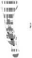
- a suitable reameris illustrated in FIG. 25A .
- the proximal reamer 100comprises an elongate first shank 101 having a first proximal end 102 and a first distal end 103.
- the first proximal endcan comprise a handle or can be configured to join to a separate handle, for example the quick connect handle 160 illustrated in FIG. 34 .
- the first distal end 103terminates in a first shaping drill end 104 terminating in a first point 106.
- a first shaping drill end 104terminating in a first point 106.
- proximal to the first point 106is a plurality of first ridges 105 having sharp edges designed to cut the hole illustrated in FIG. 25C .
- Proximal to the first ridgesis a first short shaft 104, and proximal to the first short shaft 104 is a first shoulder 107, wider than the first short shaft 104 and having the approximate diameter of the first shank 101.
- Proximal to the first shoulder 107is a first skirt 108, wider than the first shoulder and having a convex first distal surface 109.
- the proximal reamer 100also comprises a first cutout 110, extending from the plurality of first ridges 105, through the first short shaft 104, the first shoulder 107, and the first skirt 108.
- the first cutout 110has sharp lateral edges 111 designed to cut through the bone as the proximal reamer 100 is rotated and driven therein.
- the hole cut by the proximal reamer 100preferably has a diameter smaller than the diameter of the spiraling thread 24 of the female component 20, such that when the female component 20 is screwed into the hole, the spiraling thread 24 will drive through the intramedullary canal of the phalanx.
- FIG. 25Bshows an example of the alignment of the female component 20 with a suitable proximal reamer 100, where the first ridges 105 and the first short shaft 104 have a diameter of 2.0 mm, while the spiraling thread 24 of the female component 20 has a diameter of 2.2 mm.
- the proximal reamer 100also reams a concave surface 112 in the face of the bone, to allow the female component 20 to fit with the male component 30 as depicted in FIG. 29 .
- the wide bore 113 cut by the first shoulder 107allows the first top 22 to be "buried” in the bone, as shown in FIGS. 30 and 31 .
- the diameter of the concave surface 112 in this exampleis about 15 mm.
- the female component 20can be inserted. That insertion can be prepared using any suitable tool.
- a suitable tool for that purposeis the proximal driver 120, partially illustrated in FIG. 26 .
- the proximal driver 120comprises an elongate first shank 121 having a first proximal end (not shown) and a first distal end 122.
- the first proximal endcan comprise a handle or can be configured to join to a separate handle, for example the quick connect handle 160 illustrated in FIG. 34 .
- the first shank 121comprises a first slidable bobbin 123.
- the distal end 122 of the proximal driver 120comprises two first half sections (not shown) operably linked to the first bobbin 123 such that sliding the first bobbin 123 forward forces these two first half sections together to hold the first top 22 of the female component 20 securely.
- the first distal end 122 of the proximal driver 120comprises a first marking 124 (e.g., a laser marking) that aligns with a first marking 125 on the first top 22 of the female component 20 to easily align the proximal driver 120 with the female component 20.
- the first top 22 of the female component 20is placed in the proximal driver 120 and the first bobbin 123 is slid forwards to securely hold the first top 22.
- the first top 22is placed in the driver such that the first marking 124 on the proximal driver 120 lines up with the first marking 125 on the first top 22.
- the female componentis then screwed into the proximal phalanx until the distal end 122 of the proximal driver 120 is even with the hole and the first marking is facing upwards.
- the preparation of the proximal end of the middle phalanx and the insertion of the male component 30 thereinproceeds similar to the insertion of the female component 20 into the distal end of the proximal phalanx described above.
- a pilot holeis drilled about 9 mm deep into the intramedullary canal of the bone, using any suitable tool, for example the pilot drill 90 shown in FIG. 24 .
- the hole for the male component 30can then be prepared using any suitable tool, for example the distal reamer 130 illustrated in FIG. 27A .
- That distal reamer 130comprises an elongate second shank 131 having a second proximal end 132 and a second distal end 133.
- the second proximal endcan comprise a handle or can be configured to join to a separate handle, for example the quick connect handle 160 illustrated in FIG. 34 .
- the second distal end 133comprises a second shaping drill end 134 terminating in a second point 136.
- a second point 136Just proximal to the second point 136 is a plurality of second ridges 135 having sharp edges designed to cut the hole illustrated in FIG. 27C .
- Proximal to the ridgesis a second short shaft 134, and proximal to the second short shaft 134 is a second shoulder 137, wider than the second short shaft 134 but having a smaller diameter than the second shank 131.
- Proximal to the second shoulder 137is a second skirt 138, wider than the second shoulder and having a concave second distal surface 139.
- the distal reamer 130also comprises a second cutout 140, extending from the plurality of second ridges 135, through the second short shaft 134, the second shoulder 137, and the second skirt 138.
- the second cutout 140has sharp lateral edges 141 designed to cut through the bone as the distal reamer 130 is rotated and driven therein.
- the second short shaft 134, the second shoulder 137, and the second skirt 138are shorter than the counterparts on the proximal reamer 100 because the male component 30, which is driven into the hole 143 ( FIG. 27 ) made by the distal reamer 130, is shorter than the female component 40, which is driven into the hole made by the proximal reamer 100.
- the hole 143 cut by the distal reamer 130( FIG. 27C ), preferably has a diameter smaller than the diameter of the spiraling thread 34 of the male component 30, such that when the male component 30 is screwed into the hole, the spiraling thread 34 will drive through the intramedullary canal of the phalanx.
- FIG. 27Bshows an example of the alignment of the male component 30 with a suitable distal reamer 130, where the second ridges 135 and the second short shaft 134 have a diameter of 2.0 mm, while the spiraling thread 34 of the male component 30 has a diameter of 2.2 mm.
- the distal reamer 130also reams a convex surface 144 ( FIG. 28 ) in the face of the bone. In these embodiments, the convex surface radius is 6mm and thus significantly smaller radius than the 15mm concave radius of the proximal bone. This allows for articulation of the toe even with a slight misalignment.
- the male component 30can be inserted. That insertion can be prepared using any suitable tool.
- a suitable tool for that purposeis the distal driver 150, partially illustrated in FIG. 28A .
- the proximal driver 150comprises an elongate second shank 151 having a second proximal end (not shown) and a second distal end 152.
- the second proximal endcan comprise a handle or can be configured to join to a separate handle, for example the quick connect handle 160 illustrated in FIG. 34 .
- the second shank 151comprises a second slidable bobbin 153.
- the second distal end 152 of the distal driver 150comprises two second half sections (not shown) operably linked to the second bobbin 153 such that sliding the second bobbin 153 forward forces these two second half sections together to hold the second top 32 of the male component 30 securely.
- the second distal end 152 of the distal driver 150comprises a second marking 154 (e.g., a laser marking) that aligns with a marking on the first top 32 of the male component 30 to easily align the distal driver 120 with the male component 30.
- the first top 32 of the female component 30is placed in the distal driver 150, preferably with the connector 40 already attached, and the second bobbin 153 is slid forward to securely hold the first top 32.
- the first top 32is placed in the distal driver 150 such that the second marking 154 on the distal driver 150 lines up with the marking on the first top 32.
- the male component 30is then screwed into the middle phalanx until the locking pin 360 or crimping pin 33 (whichever is used) is even with the hole and the second marking is facing upwards.
- the connector 40can be adjusted to the desired angle in relation to the second top 32 at this point and the locking pin 360 or crimping pin 33 can be engaged. Alternatively, the connector 40 can be partially pushed into the female component 20 before the locking pin 360 or crimping pin 33 is engaged. If the surgeon decides not to engage the locking pin 360 or crimping pin 33, thus allowing for joint movement, the connector 40 can be fully inserted into the female component 20.
- FIG. 29shows the alignment of the two bones after insertion of the device.
- FIG. 30shows the device in cross section when partially engaged;
- FIG. 31shows the fully engaged device in cross section.
- the ability of the connector 40 to rotate in relation to the second top 32provides an advantage in inserting the devices described herein over similar prior art devices not having that ability, as shown in FIG. 32 .
- the two bones to be joinede.g., the proximal and middle phalanges
- the central portion 42aanalogous to the connector 40 of the instant device
- the tissue connecting the two bonese.g ., blood vessel 155, must be stretched when the bones are pulled apart, potentially causing damage to the tissues.
- the connector 40before the connector 40 is inserted into the female portion 20 from the first top 22, the connector 40 can be rotated in relation to the second top 32, as shown in FIG. 32B .
- the two bonesthus need not be pulled apart as far as with the prior art devices.
- Distance d in FIG. 32Bshows the reduction in this potentially damaging stretching that is saved over the prior art device when the present devices are used, minimizing tissue damage and making the insertion of the connector 40 into the female component 20 easier.
- the proximal reamer 100, the proximal driver 120, the distal reamer 130 and the distal driver 150can each have their own handle or can utilize a common handle, for example the quick connect handle 160 illustrated in FIG. 34 .
- Connecting means for such handlesare known in the art.
- FIG. 33shows the quick connect handle in use with the proximal driver 120.
- the elongate shank of any of these toolscan comprise gripping elements, e.g ., a rubber grip, to allow the surgeon to use the tool without a handle while maintaining a firm grip on the tool.
- any of the proximal or distal reamer or proximal or distal drivercan comprise, on its proximal end the cutting portion of a proximal or distal reamer or proximal or distal driver.
- the proximal reamer(comprising a shaping drill end with a convex first distal surface 109 at its distal end) can comprise the shaping drill end of the distal reamer (comprising a shaping drill end with a concave second distal surface 139) at is proximal end.
- the proximal reamercan comprise at its proximal end the slidable bobbin 123 and the two first half sections operably linked to the bobbin of the proximal driver.
- Any combination tool independently having, at its proximal and distal ends, any of the shaping drill end of the proximal or distal reamer or the bobbin and two half sections of the proximal or distal driveris envisioned herewith.
- multiple toolsmay be combined into a single tool, e.g., with one end for reaming and the other end for driving.
- the portion of the handle between the two toolsmay have grooves, cross hatching, or a gripping material to provide gripping capabilities for the person using the tools.
- any or all of the various tools described herein, including the pin locking tool 60can also be provided sterilized in a package, such as a molded sterilization tray.
- the bone fixation device 10, in any embodiment described abovecan be packaged in a sterile package as appropriate, for example in a chevron pouch 170, as shown in FIG. 34 .
- the various bone joining devices described abovemay include templates for use when drilling, reaming, driving, inserting the device or cutting the bones.
- the templatesare useful to ensure that the installation of the device is accomplished with precision and accuracy.
- a templatemay be used to align the proximal reamer or distal reamer to the bone, such that the hole prepared by the reamer is parallel with the long axis of the bone.
- Such a templatecould comprise a component that attaches ( e.g. , by screws) to the end of the bone and extends outward from the bone and provide a hole to provide a straight guide for the cutting tip of the reamer.
- the design and preparation of such templatesare known in the art.
Landscapes
- Health & Medical Sciences (AREA)
- Orthopedic Medicine & Surgery (AREA)
- Life Sciences & Earth Sciences (AREA)
- Surgery (AREA)
- Animal Behavior & Ethology (AREA)
- Veterinary Medicine (AREA)
- Public Health (AREA)
- Engineering & Computer Science (AREA)
- Biomedical Technology (AREA)
- Heart & Thoracic Surgery (AREA)
- General Health & Medical Sciences (AREA)
- Molecular Biology (AREA)
- Medical Informatics (AREA)
- Nuclear Medicine, Radiotherapy & Molecular Imaging (AREA)
- Transplantation (AREA)
- Oral & Maxillofacial Surgery (AREA)
- Neurology (AREA)
- Cardiology (AREA)
- Vascular Medicine (AREA)
- Physical Education & Sports Medicine (AREA)
- Dentistry (AREA)
- Prostheses (AREA)
- Surgical Instruments (AREA)
Description
- This application relates to devices and methods for joining bones.
- Hammertoe deformity, the most common deformity of the lesser toes, is a flexion deformity of the Proximal interphalangeal (PIP) joint of the toe, with hyperextension of the metatarsophalangeal (MTP) and distal interphalangeal (DIP) joints. Progressive PIP joint flexion deformity typically leads to compensatory hyperextension of the MTP and DIP joints. This makes the PIP joint prominent dorsally. Pain occurs due to rubbing of the prominence against the patient's shoe. The deformity is flexible at first but usually becomes fixed over time. When the deformity is flexible, various procedures can be utilized that involve manipulation of the involved tendons. However, when the deformity is fixed, PIP fusion or joint replacement is often required. Implants available for this purpose include the Weil-Carver™ Hammertoe Implant (Biomet®, Inc., Warsaw, IN), Flexible Digital Implant (Tomier, Inc. Edina, MN), SHIP Implant (Sgarlato Labs, Campbell CA), Digital Compression Screw (BioPro®, Port Huron MI), Smart Toe™ Intramedullary Memory Implant (Memometal Inc., Memphis TN) and StayFuse™ Intramedullary Fusion Device (Tornier, Inc. Edina, MN). The latter three implants are used when fusion is desired, since the other implants allow some flexibility of the joint. With all current implants, placement is critical because, when mounted, there is no adjustability in the angle of flexion between the two cut bones to be joined.
- Document
US 6,458,134 discloses a bone connector system comprising first and second connector members, which does not allow the flexion between said two bones. DocumentEP 1 632 200 discloses a bone joining device suitable for joining together a first and a second bone pieces. More specifically, the bone joining device comprises two shaft parts, a receptor part with a spherical cup and a ball joint for insertion in the receptor part. DocumentUS 5,417, 692 discloses a bone fixation and fusion system which does not control the rotation from one member to the other one. - There is thus a need for alternative designs for implants for joining two bone pieces, including implants that fix the two bone pieces, particularly designs that allow adjustment of the angle of flexion between the two bones. The present invention addresses that need.
- A bone joining device is provided that allows adjustment of the angle between the two bones to be joined.
In some embodiments, a bone joining device suitable for joining a first bone piece to a second bone piece is provided. The device comprises a first component and a second component, wherein
the first component comprises
a first elongated stem portion comprising a first end and a first top opposite the first end, the first elongated stem portion suitable for insertion from the first end longitudinally into a surface of the first bone piece, and
the second component comprises
a second elongated stem portion comprising a second end and a second top, the second elongated stem portion suitable for insertion from the second end longitudinally into a surface of the second bone piece, and
a connector extending from the second top,
wherein the connector is capable of coupling with the first component and locking therewith, wherein the first elongated stem portion of the first component includes an opening comprising a cavity comprising a wall, a closed distal end and an open proximal end, and the connector is elongated and fits within the cavity,
wherein each of the first elongated stem portion and the second elongated stem portion are each cylindrical, conical or a combination thereof, and comprises a spiraling thread,
wherein the connector comprises a shaped shaft, wherein the shaped shaft comprises a plurality of axially deposed indentations or ridges on at least one portion of the shaped shaft,
wherein the first elongated stem portion comprises: - an indentation at least partially circumscribing the first top, with at least one hole passing through the first top into the cavity, and
- a knobbed c-ring or o-ring comprising at least one knob protruding inward, the knobbed c-ring or o-ring configured to fit into the indentation in the first top such that the at least one knob fits into the at least one hole and protrudes into the cavity, and
- According to one embodiment, the connector is angularly set with respect to the second top. According to one embodiment, the device is made from (a) titanium, (b) an alloy of titanium with about 6% aluminum and about 4% vanadium, (c) nitinol, (d) stainless steel, or (e) poly ethyl ethyl ketone (PEEK).
- According to one embodiment, the connector can be separated from the first component after insertion by rotating the connector in relation to the first component causing the at least one knob to slide out of the indentation or gap between two ridges of the connector, and onto a portion of the shaft that does not comprise an indentation or ridges, and then sliding the connector out of the first component while maintaining the at least one knob along the portion of the shaft that does not comprise an indentation or ridges.
- According to one embodiment, the knobbed c-ring or o-ring is a c-ring with two ends and a middle, comprising a knob in the middle of the c-ring such that the knob encounters a plurality of axially deposed indentations or gaps on one portion of the shaft when the connector is inserted into the cavity. According to one embodiment, the knobbed c-ring comprises two knobs, such that each knob encounters a plurality of axially deposed indentations or gaps on two portions of the shaft when the connector is inserted into the cavity. According to one embodiment, the knobbed c-ring or o-ring is a c-ring with two ends and a middle, and the two knobs are between the middle and the ends of the c-ring.
- According to one embodiment, the shaft of the connector comprises a plurality of axially deposed indentations or gaps on two portions of the shaft and the knobbed c-ring or o-ring is a c-ring with two ends, comprising one knob at each end of the c-ring, such that each knob encounters a plurality of axially deposed indentations or gaps on two portions of the shaft when the connector is inserted into the cavity. According to one embodiment, tthe cylindrical shaft comprises axially deposed indentations or ridges on two opposing sides of the shaft. According to one embodiment, the device comprises three indentations or four ridges on each of the two opposing sides of the cylindrical shaft.
- According to one embodiment, when the connector is inserted into the cavity such that the knob encounters an indentation or gap, the indentation or gap is shaped such that the connector cannot be pulled out of the cavity when the knob is in the indentation or gap. According to one embodiment, each of the axially deposed indentations or ridges comprises a distal edge that is substantially perpendicular to the wall of the cavity. According to one embodiment, each of the axially deposed indentations comprises a distal edge that forms an acute angle with the shaft of the connector. According to one embodiment, when the connector is inserted into the cavity such that the knob encounters an indentation or gap, the presence of the knob in the cavity limits the rotation of the connector in the cavity.
FIG. 1 is a perspective view of one embodiment of the invention bone joining device showing the female component and the male component aligned for joining.FIG. 2 is a sectional view of one embodiment of the invention bone joining device showing the female component and the male component aligned for joining.FIG. 3 is a perspective view of one embodiment of the bone joining device after partial insertion of the connector into the female component.FIG. 4 is a sectional view of one embodiment of the bone joining device after partial insertion of the connector into the female component.FIG. 5 is an enlarged fragmentary view of one embodiment of the bone joining device after partial insertion of the connector into the female component.FIG. 6 is an enlarged fragmentary view of one embodiment of the bone joining device after partial insertion of the connector into the female component.FIG. 7 is a side elevation longitudinal sectional view of a bone with one embodiment of the bone joining device in place after partial insertion of the connector into the female component.FIG. 8 is a perspective view of one embodiment of the invention bone joining device showing the female component and the male component after full insertion of the connector into the female component.FIG. 9 is a sectional view of one embodiment of the invention bone joining device showing the female component and the male component after full insertion of the connector into the female component.FIG. 10 is a side elevation longitudinal sectional view of a bone with one embodiment of the invention bone joining device in place after full insertion of the connector into the female component.FIG. 11 is a perspective view of one embodiment of the male component of the invention bone joining device.FIG. 12 is an exploded perspective view of one embodiment of the male component of the invention bone joining device.FIG. 13 is a perspective view of one embodiment of the female component of the invention bone joining device.FIG. 14 is a sectional view of one embodiment of the female component of the invention bone joining device.FIG. 15 is an exploded perspective view of one embodiment of the invention bone joining device.FIG. 16 is a perspective, partial see-through view of one embodiment of the invention bone joining device after partial insertion of the connector into the female component.FIG. 17 is a perspective, see-through view of one embodiment of the invention bone joining device after full insertion of the connector into the female component.FIG. 18 is an exploded perspective view of one embodiment of the invention bone joining device.FIG. 19 is a perspective (Panel A) and a cross-sectional (Panel B) view of one embodiment of a crimping shaft of the invention bone joining device.FIG. 20 is two perspective views of one embodiment of a pin locking tool.FIG. 21 is a perspective (Panel A) and a cross-sectional (Panel B) view of one embodiment of a connector of the invention bone joining device.FIG. 22 is a perspective (Panel A) and two cross-sectional (Panels B and C) view of one embodiment of a female component of the invention bone joining device.FIG. 23 are three perspective views of one embodiment of the invention bone joining device.FIG. 24 is a perspective view of a pilot hole drilling device of one embodiment of the invention bone joining device.FIG. 25 is a perspective view of one embodiment of a proximal reamer (Panel A), a perspective view of the proximal reamer aligned with a female component (Panel B) and a perspective view of a sectioned bone showing a hole drilled by the proximal reamer (Panel C).FIG. 26 is a perspective view of a portion of a proximal driver and a female component (Panel A), and a section of the proximal driver and female component inserted into a bone (Panel B).FIG. 27 is a perspective view of one embodiment of a distal reamer (Panel A), a perspective view of the distal reamer aligned with a male component (Panel B) and a perspective view of a sectioned bone showing a hole drilled by the distal reamer (Panel C).FIG. 28 is a perspective view of one embodiment of a distal driver aligned with a bone (Panel A) and a bone with a male component inserted therein.FIG. 29 is perspective views of proximal and middle phalanges of a lesser toe aligned as when the invention bone joining device is inserted therein.FIG. 30 is a sectional view of the invention bone joining device inserted into proximal and middle phalanges of a lesser toe.FIG. 31 is a sectional view of the invention bone joining device inserted into proximal and middle phalanges of a lesser toe.FIG. 32 is a cross section of the insertion of the two parts of a prior art device (Panel A) and the invention bone joining device (Panel B) showing the comparative stretching of surrounding tissues during the insertion of each device.FIG. 33 is a perspective view of a proximal driver with a handle during insertion of the invention bone joining device into a proximal phalanx.FIG. 34 is a perspective view of the invention bone joining device and tools used to install the device as prepared for packaging.- The inventors have developed a bone joining device that allows adjustment of the angle between the two bones to be joined.
- In some embodiments, the application is directed to a bone joining device suitable for joining a first bone piece to a second bone piece. The device comprises a first component and a second component, wherein the first component comprises a first elongated stem portion comprising a first end and a first top opposite the first end, the first elongated stem portion suitable for insertion from the first end longitudinally into a surface of the first bone piece, and the second component comprises a second elongated stem portion comprising a second end and a second top, the second elongated stem portion suitable for insertion from the second end longitudinally into a surface of the second bone piece. The device further comprises a connector extending from the second top. The connector is capable of joining with the first component and locking therewith.
- The connector may join with the first component by any means known in the art. Non-limiting examples of such joining means include knobs, clamps, teeth, glues, Velcro® and staples. In some embodiments, the first component is a female component and the second component is a male component, wherein the first elongated stem portion of the female component further comprises an opening that extends axially from the first top toward the first end; and the connector comprises an elongated shaft, a proximal end, a top of shaft near the proximal end, and a distal end, wherein the connector is capable of insertion into the opening in the first elongated stem portion and locking therein. The figures provide several examples of these devices, as detailed below.
- The device is generally useful for joining any two bone pieces, for example two vertebrae or two halves of a broken bone. In some embodiments, the device is particularly useful for joining or fusing cut surfaces of bones, in particular the cut ends of long bones, especially fingers or toes,e.g., for joining or fusing a joint on a lesser toe, for example to treat hammertoe, claw toe, mallet toe or curly toe. In those embodiments, the first stem portion is suitable for insertion from the first end longitudinally into a cut surface of a resected phalanx, metatarsal or metacarpal, or a cut diaphysis, and the second stem portion is suitable for insertion from the second end longitudinally into a cut surface of a resected phalanx, metatarsal or metacarpal, or a cut diaphysis. The device can also be used to fuse a metatarsal that has been shortened by resection.
- Various, nonlimiting embodiments of the device are shown in
FIGS. 1-33 , where thebone joining device 10 is provided as afemale component 20 and amale component 30. Thefemale component 20 of this embodiment is an elongated stem, and comprises afirst end 21, a first top 22 and acylindrical cavity 29, best shown inFIGS. 2 ,13 ,14 and22 , comprising acylindrical wall 23, a closeddistal end 27 and an openproximal end 28. The illustratedfemale component 20 also comprises acontinuous spiraling thread 24 on the exterior of the component, suitable for screwing the component into a bone. Thefemale component 20 is also referred to herein as the "first elongated stem portion." The cavity and wall can have any shape cross section as defined by the cavity wall, including, for example, circular, oval, rectangular hexagonal and octagonal. - The
male component 30, best shown inFIGS. 1 ,2 ,4 ,7 ,10 ,11 ,12 ,15 ,18 and23 , comprises a secondelongated stem portion 37 comprising asecond end 31 and a second top 32, with aconnector 40 extending from the second top 32. Themale component 30 is also referred to herein as the "second elongated stem portion." The illustrated second elongatedstem portion 37 comprises acontinuous spiraling thread 34 on the exterior, where the thread is suitable for screwing the component into abone 50. - The
female component 20 and themale component 30 can independently be cylindrical or conical, or any combination thereof,e.g., cylindrical at the proximal end, transitioning into a conical shape. - While the illustrated embodiments show a spiraling thread as a means to anchor the male component and the female component into the bone, any alternate anchoring means can be used, for example barbs, a shape memory expanding means (e.g., as featured in the Smart Toe™ Implant (Memometal Inc., Memphis TN), or any other anchoring means known in the art.
- Where present, the spiraling threads on the device can be of any type known in the art for screwing into a bone. In some embodiments, the spiraling thread is a continuous spiraling thread. In other embodiments, the spiraling thread allows self-tapping and/or self-threading of the first elongated stem portion into the first bone piece and the second elongated stem portion into the second bone piece. See,e.g., 240 of
FIGS. 15-17 . - In some embodiments, the
continuous spiraling thread - These embodiments are not limited to any particular pitch of one rotation of the continuous spiraling thread. For example, the pitch may be 5 mm or greater, 4 mm, 3 mm, 2 mm, 1 mm, less than 1 mm, or any distance in between these distances.
- In some embodiments, the
connector 40 is as shown inFIGS. 1 ,11 and12 . In those embodiments, theconnector 40 extends from the second top 32 and comprises aproximal end 41, a top ofshaft 46 near theproximal end 41, and adistal end 42. Theproximal end 41 comprises aconnector hole 47, best shown inFIG. 12 , that is joined to the second top 32 in arecess 35 with crimpingpins 33 and a crimpingshaft 36. When so joined, theconnector 40 can be adjustably positioned in an angular direction in relation to the second top 32 until the crimpingpins 33 are crimped toward each other along the crimpingshaft 36, forcingouter flanges 36a outward, which engage theconnector hole 47, causing friction between theouter flanges 36a and theconnector hole 47 and preventing further adjustable positioning of theconnector 40 in relation to the second top 32. - The
connector hole 47 in combination with the crimpingshaft 36 serves as a locking mechanism that prevents adjustable positioning of theconnector 40 in relation to the second top. In use, thedistal end 42 of theconnector 40 is inserted into the openproximal end 28 of thefemale component 20, penetrating thecylindrical cavity 29 to a certain point,e.g., as inFIG. 3-7 and16 . This partial insertion feature allows theconnector 40 to then be adjusted to the desired angle in relation to the second top 32 before the device is inserted to its final position. The crimping pins 33 are then crimped, using any tool that can push the two crimpingpins 33 simultaneously into the crimpingshaft 36, preventing further angular movement in relation to the second top. Theconnector 40 is then further inserted into the shaft to the desired final position. - An alternative embodiment to a crimping shaft to prevent positioning of a
connector 40 in relation to a second top 32 is illustrated inFIG. 19 . As illustrated therein, the crimping shaft is substituted with alocking pin 360 that has a tapered cylindrical shape having anarrow end 362 and awide end 364. Although the ends can be of any appropriate configuration, in the illustrated embodiment, both thenarrow end 362 and thewide end 364 have inwardly directedindentations locking pin 360 into theconnector hole 47. In use, the lockingpin 360 is inserted partly into theconnector hole 47 from thenarrow end 362, where it acts as an hinge that connects theproximal end 41 of theconnector 40 with thesecond top 32 of the secondelongated stem portion 37, allowing angular positioning of theconnector 40 in relation to the second top 32. When theconnector 40 is in the desired angular position in relation to the second top 32, thewide end 364 of thelocking pin 360 is pushed further into theconnector hole 47, causing friction between thewide end 364 of thelocking pin 360, theconnector hole 47, and thesecond top 32 of the secondelongated stem portion 37, frictionally preventing further movement of theconnector 40 in relation to the second top 32. - In these embodiments, the locking
pin 360 can be pushed into theconnector hole 47 using any suitable tool, for example a modified tissue clamp, a modified k-wire pliers, or thepin locking tool 60 illustrated inFIG. 20 . As illustrated, thepin locking tool 60 comprises ahandle 62 comprising a thumb hole andfinger hole scissor hinge 65 to bring together distal ends 66, 67 when the thumb hole andfinger hole Distal end 66 is terminated by a contouredformation 68, which is configured to engage the second top 32.Distal end 68 is terminated by apin formation 69, which is configured to engage thewide end 364 of thelocking pin 360. In that position, when the surgeon pulls the thumb hole andfinger hole pin formation 69 pushes thewide end 364 of thelocking pin 360 into theconnector hole 47, locking theconnector 40 in the desired angular position in relation to the second top 32. AlthoughFIG. 20 shows the engagement of thelocking pin 360 before theconnector 40 is joined to thefemale component 20, the lockingpin 360 can also be so engaged after theconnector 40 is so joined,e.g., after theconnector 40 is partially inserted into thefemale component 20, as illustrated inFIGS. 3-7 . Additionally, thepin locking tool 60 can be used with the crimpingpins 33 and a crimpingshaft 36 described above and illustrated inFIG. 12 , or with any other suitable component. - In some embodiments, the angle of the
connector 40 is not locked in relation to the second top 32,e.g., when fixation is not desired, allowing flexion between the bone pieces such that the connector 40 - second top 32 forms a joint, for example a PIP, a DIP or an MTP joint. In these embodiments, the lockingpin 360 or crimpingpin 33/crimpingshaft 36 is not pushed into theconnector hole 47, or is only pushed in part way, to allow the desired degree of flexion. Alternatively, a simple pin or any other component can be inserted into the connector hole rather than the lockingpin 360 or crimpingpin 33/crimpingshaft 36, to provide a hinge for the joint. - The
connector hole 47 and/or crimpingshaft 36 can be designed so that theconnector 40 is limited in angular movement in relation to the second top 32. In some embodiments, theconnector 40 is capable of being adjustably positioned at an angle of at least 10° in each of a forward direction and a reverse direction in relation to the second top 32. In other embodiments, theconnector 40 is capable of being adjustably positioned at an angle of at least 90° in each of a forward direction and a reverse direction in relation to the second top 32. SeeFIG. 6 . In additional embodiments, theconnector 40 is capable of being adjustably positioned at an angle of at least 120° in each of a forward direction and a reverse direction in relation to the second top 32. In still other embodiments, theconnector 40 is capable of being adjustably positioned at an angle of at least 150° in each of a forward direction and a reverse direction in relation to the second top 32. - In alternative embodiments, the
connector 40 is coupled to the second top 32 using a snap-lock, where theconnector 40 can lock in the firstelongated stem portion 20 without further insertion of theconnector 40 into the firstelongated stem portion 32. - In some embodiments, the
cylindrical cavity 29 of thefemale component 20 is designed to receive theconnector 40 through theproximal end 28 of the cavity 29 (FIG. 13 and14 ). In these embodiments, theconnector 40 is elongated and cylindrical. The connector further comprises aring 44 formed around thedistal end 42, where thering 44 has a diameter larger than the diameter of thecylindrical cavity 23 and cross slits 43 directed axially from thedistal end 42 toward theproximal end 41 of theconnector 40, thereby forming a spring collet 45 (shown inFIGS. 1 ,2 ,4 ,9 ,11 and12 ). - To accommodate the
connector 40 in these embodiments, thecylindrical cavity 29 further comprises at least a first ring-shaped recess 25a circumscribing thecylindrical wall 23 near the distal end such that, when theconnector 40 is inserted into thecylindrical cavity 29, thespring collet 45 is compressed until thering 44 encounters the first recess 25a, where the first recess 25a accommodates a less compressed diameter of thering 44 and thespring collet 45 transitions to a less compressed state.FIGS. 3-7 show the illustrated embodiment at that position. - To prevent the
connector 40 from being pulled out of thecylindrical cavity 29, thering 44 can comprise anedge 48 on the side closer to theproximal end 41 of theconnector 40, where the edge is designed to prevent movement of theconnector 40 in the proximal direction after encountering the ring-shaped recess 25a. In the illustrated embodiment, theedge 48 is substantially perpendicular to thewall 23 of thecylindrical cavity 29. In other embodiments, theedge 48 forms an acute angle with the perimeter of theconnector 40. - In the illustrated embodiment, the
wall 23 of thecylindrical cavity 29 further comprises a second ring-shaped recess 25b circumscribing thecylindrical wall 23 closer to thedistal end 27 than the first recess 25a, where theconnector 40 can be inserted beyond the first recess 25a, compressing thespring collet 45 until thering 44 encounters the second recess 25b, where the second recess 25b accommodates a less compressed diameter of thering 44 and thespring collet 45 transitions to a less compressed state. - The distance between the recesses 25a and 25b in the
wall 23 of thecylindrical cavity 29 can be any distance appropriate for the particular application. The distance may be 5 mm or greater, 4 mm, 3 mm, 2 mm, 1 mm, less than 1 mm, or any distance in between these values. In some embodiments, the distance is anywhere from 0.2 mm to 1 mm, for example about 0.6 mm. - In the illustrated embodiment, the
wall 23 of thecylindrical cavity 29 further comprises a third ring-shaped recess 25c circumscribing thecylindrical wall 23 closer to thedistal end 27 than the second recess 25b, where theconnector 40 can be inserted beyond the second recess 25b, compressing thespring collet 45 until thering 44 encounters the third recess 25c, where the third recess 25c accommodates a less compressed diameter of thering 44 and thespring collet 45 transitions to a less compressed state. - In the illustrated embodiment, the
wall 23 of thecylindrical cavity 29 additionally comprises a fourth and fifth ring-shaped recess 25d and 25e circumscribing thecylindrical wall 23 closer to thedistal end 27 than the third recess 25c, where theconnector 40 can be inserted beyond the third recess 25c, compressing thespring collet 45 until thering 44 encounters the fourth recess 25d or fifth recess 25e, where the fourth and fifth recess 25d and 25e accommodates a less compressed diameter of thering 44 and thespring collet 45 transitions to a less compressed state.FIGS. 8-10 show the illustrated embodiment in that position. - In the operation of the illustrated embodiment, when the
connector 40 is inserted into thecylindrical cavity 29 and thespring collet 45 engages the first recess, theconnector 40 continues to be capable of being adjustably positioned in relation to the second top 32. This is best illustrated inFIGS. 3 ,4 and6 , also showing that when thespring collet 45 is engaged in the first recess 25a, there is a gap between the second top 32 and the first top 22, such that the top of theshaft 46 of theconnector 40 is exposed. The gap provides room for the second top to adjustably position the secondelongated stem portion 37 to any angle desired.FIG. 7 illustrates the device in a digit, showing the gap between the second top 32 and the first top 22.FIG. 7 also illustrates that, when thespring collet 45 engages the first recess 25a, the device provides continuous adjustability of themale component 30 in relation to theconnector 40 in the flexion of the joint. Thus, using the invention device, the joint can be flexed to any degree necessary. If fusion is desired, that fusion can be made at the desired angle of flexion. - In some embodiments, when the
female component 20 and themale component 30 are screwed into thebone pieces 50, those two components should rotationally align with each other so that the top of theshaft 46 can fit inside the proximal end of thecylindrical cavity 29. Additionally, when the device is used to fuse a digit, as ine.g., hammertoe treatment, the positioning of theconnector 40 in an angular direction should be made in the proper rotational plane, such that theconnector 40 can be positioned along an angle that follows the natural flexion of the digit. The identity of the proper alignment of the female and male components can be accomplished by any means, for example by providing marks on the first top 22 and near theproximal end 41 of theconnector 40, where the marks align at the desired position of themale component 30 andfemale component 20 when thering 44 is in the first recess 25a. Additionally, when thering 44 is in the first recess 25a, theconnector 40 may be adjusted to the desired angle in relation to the second top 32 and the crimpingpins 33 crimped, preventing further angular movement of theconnector 40 in relation to the second top 32. - The device may additionally comprise any means to prevent rotation of the
connector 40 in relation to the firstelongated stem portion 20, and to assure that themale component 30 andfemale component 20 are properly aligned rotationally. In some embodiments, as illustrated inFIGS. 15-18 , theconnector 40 comprises agroove 401 along the length of the connector, and the firstelongated stem portion 20 further comprises apin hole 231 through the side of the firstelongated stem portion 20, thepin hole 231 further comprising ananti-rotation pin 201 capable of fitting in thegroove 401 of theconnector 40 when theconnector 40 is inserted into the proximal end of thecavity 29 of the firstelongated stem portion 20. Theanti-rotation pin 201 prevents rotation of theconnector 40 in relation to the firstelongated stem portion 20 when the anti-rotation pin is in thegroove 401 of theconnector 40. - In the embodiments illustrated in
FIGS. 15-18 , theconnector 40 further comprises at least two shaft-rings 441 surrounding and protruding from the shaft. Eachshaft ring 441 varies from the other shaft-ring(s) in their proximity to the distal end of the shaft. The circumference of the shaft-rings 441 is slightly less than the circumference of thecylindrical cavity 29 in the firstelongated stem portion 20 of the female component. Six shaft rings are in the device shown inFIGS. 15-17 , and three in the device shown inFIG. 18 . Thecylindrical cavity 29 in the first elongated stem portion of the female component further comprises aslot 221 circumscribing thecylindrical wall 23 near theproximal end 28 of thecavity 29. Theslot 221 further comprises a c-ring 211 fitting therein. - In these embodiments, the c-
ring 211 protrudes into thecavity 29 when relaxed. However, the c-ring 221 expands and recedes into theslot 221 when theconnector 40 is inserted into thecavity 29 and a shaft-ring 441 encounters the c-ring 221 and pushes against it. This allows theshaft ring 441 to pass the c-ring 221. After theshaft ring 441 passes the c-ring 221, providing space in thecavity 29 to accommodate the relaxed c-ring, the c-ring 221 becomes relaxed again and contracts, re-protruding into thecavity 29. It is envisioned that, after theconnector 40 is inserted into thecavity 29 such that the most distal (or second or third most distal) shaft-ring 441 passes the c-ring 221, as inFIG. 16 , theconnector 40 is manually rotationally adjusted in relation to themale component 30 to the final desired position(e.g., the desired angle of flexion of a joint being fused, or a properly aligned position of the two parts of a broken bone or vertebral fusion). The crimpingpin 33 is then crimped, to prevent further rotational movement. Theconnector 40 may then inserted the rest of the was into thecavity 29, as inFIG. 17 , aligning the two bone pieces. It is noted that, inFIG. 17 , all six shaft rings 441 have passed the c-ring 221. In the alternate design illustrated inFIG. 18 , there are three shaft rings 441. - In the illustrated embodiments, the top of the
shaft 46 of theconnector 40 comprises ahexagonal formation 49 and the first top 22 comprises ahexagonal recess 26, where thehexagonal formation 49 fits into thehexagonal recess 26 when theconnector 40 is inserted into thecylindrical cavity 29. In other embodiments, the formation and recess can be circular, pentagonal, square or any other shape. - In some embodiments, the first top 22 is concave and the second top 32 is convex, as shown,e.g., in
FIG. 5 , such that, when screwed into the bones, the first top 22 and the second top 32 match common osteotomy cuts where one bone is cut in a concave shape and the other bone is cut in a convex shape. - In some embodiments, at least one of the
hexagonal recess 26 and thehexagonal formation 49 is smoothed where theconnector 40 first encounters thehexagonal recess 26 such that thehexagonal formation 49 will fit into thehexagonal recess 46 even if the marks are not fully aligned at the desired position. - An alternative configuration of the bone fixation device is illustrated in
FIGS. 21-23 . As in the embodiments described above and illustrated inFIG. 21 , theconnector 40 of this configuration comprises aproximal end 41 having aconnector hole 47, a top ofshaft 46 near theproximal end 41, and adistal end 42. In this alternative configuration, theshaft 70 of theconnector 40 is cylindrical, with a plurality (here, three) of axially deposedindentations 250a-c, 252a-c on at least one side of theshaft 70. In various embodiments, theconnector 40 may be elongate but not cylindrical,e.g., key-shaped, having a plurality of axially deposed ridges, such as, for example, semicircular, or arced ridges. For the embodiments illustrated inFIGS. 21-23 , thecylindrical shaft 70 of theconnector 40 comprises a second set of three axially deposedindentations 250a-c, 252a-c on opposing sides of the shaft. - As shown in
FIG. 22 , thefemale component 20 of this embodiment is an elongated stem, comprising afirst end 21, a first top 22, an openproximal end 28 and acylindrical cavity 29. Thecylindrical cavity 29 comprises acylindrical wall 23, a closeddistal end 27 and an openproximal end 28. The illustratedfemale component 20 also comprises a spiralingthread 24 on the exterior of the component, suitable for screwing the component into a bone. - The
female component 20 also comprises anindentation 72 at least partially circumscribing the first top 22, with at least one (here, two)hole cylindrical cavity 29. - The
female component 20 additionally comprises a knobbed c-ring 80, comprising at least one (here, two) knob protruding inward 82, 84. The knobbed c-ring 80 is configured to fit into theindentation 72 in thefirst top 22 of thefemale component 20, such that the knobs fit into theholes cylindrical cavity 29. - In use (
FIG. 23 ), theconnector 40 is joined to themale component 30 at theconnector hole 47 by inserting thenarrow end 362 of the locking pin 360 (as illustrated inFIG. 23 ) or the crimpingshaft 36 and crimping pins 33 (as illustrated inFIG. 12 ) through the hole on one side of the second top 32 and into theconnector hole 47. Theshaft 70 of theconnector 40 is inserted into the openproximal end 28 and into thecylindrical cavity 29 of thefemale component 20, where thedistal end 42 of theshaft 70 encounters theknobs ring 80, which are protruding into thecylindrical cavity 29. As theshaft 70 of theconnector 40 is pushed further into thecylindrical cavity 29, thedistal end 42 of theshaft 70 pushes on theknobs ring 80 such that theknobs cylindrical cavity 29 to accommodate theshaft 70, until theknobs cylindrical cavity 29 in the space created by the indentations, such that the knobbed c-ring 80 compresses back to its original shape. To prevent theconnector 40 from being pulled out of thecylindrical cavity 29, theindentations 250 can comprise anedge 480 on the side closer to thedistal end 42 of theconnector 40, where the edge is designed to prevent movement of theconnector 40 in the proximal direction after encountering theindentation 250. In the illustrated embodiment, theedge 480 is substantially perpendicular to thewall 23 of thecylindrical cavity 29. In other embodiments, theedge 480 forms an acute angle with the perimeter of theshaft 70. When theshaft 70 of theconnector 40 continues to be pushed further into thecylindrical cavity 29, the knobbed c-ring 80 again expands as the area between the first indentations 250c,f and thesecond indentations 250b,e pushes theknobs cylindrical cavity 29, until theknobs second indentations 250b,e. This continues until theknobs male component 30, when the device is seated in its final position. At some point before the device is in its final position, the desired angle of flexion between theconnector 40 and themale component 30 is made and set by,e.g., fully engaging thelocking pin 360 using thepin locking tool 60, or crimping the crimpingpins 33 into the crimping shaft 36 (FIG. 12 ), as appropriate. - The various steps described above can be performed in any order,i.e., before or after the insertion into either or both bone pieces. It should also be understood that the described embodiments are exemplary, and any appropriate modifications can be made to the devices described above. For example, the knobbed c-ring can instead be an o-ring, and/or can comprise one, or any number of knobs in conjunction with a matching number of aligning sets of axially deposed indentations. Additionally, the knob or knobs can be deposed anywhere along the c-ring,e.g., in the middle of the c-ring, on one or both ends, or between the middle and one or both end. Further, the knobbed c-ring or o-ring can be utilized in conjunction with the connectors described in any of
FIGS. 16-18 , or any similar connector, instead of the c-ring 211 andanti-rotation pin 201 described previously. - In embodiments where the indentations or ridges do not substantially circumscribe the connector, the presence of the knob in the cavity or the gap between ridges has the advantage of limiting the rotation of the connector in the cavity or the gap between ridges, since the presence of the knob in the cavity or the gap between ridges limits any rotation to the width of the indention or the gap between ridges, unless additional force is applied in rotating the connector to force the knob(s) out of the indentation or the gap between ridges, as described in the following paragraph.
- The embodiment illustrated in
FIGS. 21-23 has the advantage of being removable. For example, theconnector 40 can be separated from thefemale component 20 by rotating theconnector 40 in relation to the female component 20 (which can be achieved after implantation by rotating one bone piece in relation to the other). This causes theknobs shaft 70 between the opposing indentations or the gap between ridges(e.g., 250a and 250d). Theconnector 40 can then slide out of thefemale component 20 along that portion of theshaft 70. - As can be seen from the immediately preceding discussion, the presence of the knob in the indentation or the gap between ridges substantially limits the rotation of the connector in the cavity. However, rotating the connector in relation to the cavity is a means for disconnecting the male and female components of the device. As such, the shape and composition of the indentation or the gap between ridges, the c-ring or o-ring, and the knob(s) can be designed to have a balance between the ease with which the male and female components can be disconnected and the force required to overcome the ability of the knob in the cavity to prevent rotation of the connector in relation to the cavity. For example, coating the indentation or the gap between ridges with,e.g., silicone or Teflon to reduce the friction between the knob and the side of the indentation or the gap between ridges, or smoothing or angling the edge of the indentation or the gap between ridges where the knob encounters the wall of the indentation or the gap between ridges when the connector is rotated, makes separation of the male and female components easier and also makes it easier for the connector to be rotated to overcome the resistance to rotation caused by the presence of the knob in the indentation or the gap between ridges. Conversely, having a relatively long knob protruding into the indentation or the gap between ridges makes separation of the male and female components more difficult and also makes rotating the connector to overcome the resistance to rotation more difficult. The number and location(s) of the knob(s) also affect the ease with which rotating the connector to overcome the resistance to rotation can be achieved. For example, using a c-ring with only one knob (corresponding to only one set of axially deposed indentations or gaps between ridges) makes such rotation easier than using a c-ring with two knobs (corresponding to two sets of indentations or gaps between ridges). Also, deposing the knobs on the end of the c-ring makes overcoming the resistance to rotation easier than deposing the knobs toward the middle of the c-ring, since the c-ring requires greater bending distance and force when the knobs are deposed toward the middle in order for them to be pushed out of the cylindrical cavity. Additionally, the use of a c-ring made of a more flexible material makes overcoming the resistance to rotation easier then using a c-ring made of a less flexible material.
- The devices described herein can be of any diameter appropriate for the particular bones being joined, as defined by the widest diameter of the spiraling
thread female component 20 or themale component 30. In some embodiments, the diameter of either component is more than 5 mm. In other embodiments, the diameter of either component is about 5 mm, about 4 mm, about 3 mm, about 2 mm, about 1 mm, less than 1 mm, or any diameter in between, for example about 2.2 mm. - The bone fixation device can be fabricated from any appropriate material. In some embodiments, the device is not bioabsorbable, since it is anticipated that the device provides stability to the fusion site. Additionally, should the two bones joined by the device fail to fuse, the device would provide essential structural support to keep the two bones together. Nonlimiting examples of materials that could be used to fabricate the device include (a) titanium, (b) an alloy of titanium with about 6% aluminum and about 4% vanadium, (c) nitinol, (d) stainless steel, and (e) a polymer such as poly ethyl ethyl ketone (PEEK).
- This application is also directed to a method of joining a first bone piece with a second bone piece in a living vertebrate. The method comprises inserting the above-described bone fixation device between the first bone piece and the second bone piece such that the two bone pieces are securely joined.
- The method can be used on any vertebrate species. In some embodiments, the vertebrate is a mammal, for example a human.
- In some embodiments, the method comprises preparing the two bone pieces to provide a cut surface on each piece that will be joined to each other; inserting the first elongated stem portion longitudinally into the cut surface of the first bone piece such that the first end is inserted first and the first top is at or slightly below the cut surface of the first bone piece; inserting the second elongated stem portion longitudinally into the cut surface of the second bone piece such that the proximal end of the connector is just above the cut surface of the second bone piece; and inserting the connector into the opening in the first elongated stem portion.
- In various embodiments, the connector is coupled to the second top at the proximal end by a coupling allowing the adjustable positioning of the connector in an angular direction in relation to the second top. In these embodiments, the method further comprises adjusting the position of the connector in relation to the second top to form a preferred angle of flexion between the two bone pieces; and further inserting the connector into the first elongated stem portion.
- In some embodiments, the position of the connector in relation to the second top can no longer be adjusted after the connector is further inserted into the first elongated stem portion. As previously described, this can be accomplished by providing a crimping pin mechanism, as provided in the illustrated embodiments.
- These methods can be used to join or fuse any two bone pieces, for example two vertebrae or two halves of a broken bone. In some embodiments, the bone pieces are (a) two adjoining phalanges; (b) a phalanx and an adjoining metacarpal; (c) a phalanx and an adjoining metatarsal; or (d) bone pieces separated by a fracture or osteotomy of a bone diaphysis. Where the subject is a human, these bones can be in the hand or the foot.
- In various embodiments, the bone pieces are in the foot of the mammal. The foot can have any condition for which the treatment involves a bone joining two bone pieces. Examples of such conditions include hammertoe, mallet toe, curly toe, or claw toe. In some embodiments, the interphalangeal, metatarsophalangeal or metacarpophalangeal joint is fused.
- In other embodiments, the bone pieces are separated by an osteotomy that shortens the bone, for example a lesser metatarsal. An example of such a procedure that can utilize the instant method is a Weil osteotomy, which shortens a metatarsal to provide an improved metatarsal parabola. In those embodiments, the two bone pieces are from a single metatarsal bone that is subjected to an osteotomy of the diaphysis.
- In methods utilizing the illustrated embodiment, the first bone is cut in a convex shape and the second bone is cut in a concave shape. These embodiments are particularly accommodated when the
first top 22 of the device is concave and the second top 32 is convex, as shown,e.g., inFIG. 5 . - Using the illustrated embodiment, these methods can further comprise procedures wherein the first bone piece and the second bone piece are cut; the
bone fixation device 10 is inserted between thefirst bone piece 50 and thesecond bone piece 50; theconnector 40 is inserted into thecylindrical cavity 29 to the first recess 25a before locking theconnector 40, where the connector is locked by crimping the crimping pins 33.FIG. 7 shows the device of the illustrated embodiment after this step. In these methods, theconnector 40 is further inserted into thecylindrical cavity 29 at least to the second recess 25b, until the cut surface on the first bone piece and the second bone piece are joined together.FIG. 10 shows the device of the illustrated embodiment after this step. - In these methods, the device can further comprise marks on the first top 22 and near the
proximal end 41 of theconnector 40, the marks aligning at the desired position of themale component 30 andfemale component 20 when theconnector 40 is inserted into the first elongated stem portion (i.e., the female component) 20. In these embodiments, the firstelongated stem portion 20 is inserted into the cut surface of thefirst bone piece 50 by screwing the firstelongated stem portion 20 longitudinally into the cut surface of thefirst bone piece 50, and the secondelongated stem portion 37 is inserted into the cut surface of thesecond bone piece 50 by screwing the secondelongated stem portion 37 longitudinally into the cut surface of the second bone piece, where the mark on the first top 22 and the mark near theproximal end 41 of theconnector 40 are adjacent to each other after insertion of the secondelongated stem portion 37. - In additional embodiments of these methods, the
proximal end 41 of theconnector 40 comprises ahexagonal formation 49 and the first top 22 comprises ahexagonal recess 26, wherein thehexagonal formation 49 fits into thehexagonal recess 26 when theconnector 41 is inserted into thefirst stem portion 20, where at least one of thehexagonal formation 49 andhexagonal recess 26 is smoothed where thehexagonal formation 49 first encounters thehexagonal recess 26 such that thehexagonal formation 49 will fit into thehexagonal recess 26 even if the marks are not fully aligned at the desired position; and the cut surface of the first bone comprises a notch to accommodate thehexagonal formation 49. - The various embodiments described above can be implanted using any appropriate tools known in the art. Alternative tools, particularly suited for the above embodiments, and methods of implanting the above bone fixation devices in a digit, exemplified on a lesser toe proximal and middle phalanges, are described below and illustrated in
FIGS. 24-33 . - In some embodiments, to fuse the proximal and middle phalanges, the interphalangeal joint is exposed and the distal end of the proximal phalanx and the proximal end of the middle phalanx are cut off perpendicular to the long axis of each bone. This creates about a 3mm gap between the bones. A pilot hole is then drilled,e.g., about 18 mm deep, in the proximal phalanx through the intramedullary canal.
- The pilot hole can be drilled using any appropriate pilot drill known in the art. In some embodiments, the pilot hole is drilled with a tool designed especially for the device described above, for example the
pilot drill 90 shown inFIG. 24 . Such a drill comprises anelongate shank 91 having aproximal end 92 and adistal end 93. The proximal end can comprise a handle or can be configured to join to a separate handle, for example thequick connect handle 160 illustrated inFIG. 34 . Thedistal end 93 terminates in adrill tip 94 comprising at least one spirally deposedflute 95 having a sharp outer edge and terminating in apoint 96. In some embodiments, as inFIG. 24 , there are two spirally deposedflutes 95. The cutting surface defined by the sharp outer edge has the same diameter as theshank 91. The diameter should be less than the diameter of the spiralingthread 24 of thefemale component 20, to be implanted therein. In some embodiments, the spiraling thread of thefemale component 20 is 2.2 mm and the diameter of theshank 91 and spirally deposedflute 94 is 2.0 mm. Some embodiments of thepilot drill 90 further comprise a mark or marks (e.g., laser markings) indicating a distance from thepoint 96 to provide a guide for determining the depth of the hole to be drilled. For example, thepilot drill 90 illustrated inFIG. 24 hasmarks - A 2.0 mm pilot hole can be drilled about 18 mm deep in the proximal phalanx through the intramedullary canal. This can be followed with a reamer to shape the hole to accommodate the
female component 20. In some embodiments, the reamer prepares a hole with a widened bore near the top to accommodate the top 22 of the female component,e.g., as illustrated inFIG. 25C . A suitable reamer is illustrated inFIG. 25A . Theproximal reamer 100 comprises an elongatefirst shank 101 having a firstproximal end 102 and a firstdistal end 103. The first proximal end can comprise a handle or can be configured to join to a separate handle, for example thequick connect handle 160 illustrated inFIG. 34 . The firstdistal end 103 terminates in a firstshaping drill end 104 terminating in afirst point 106. Just proximal to thefirst point 106 is a plurality offirst ridges 105 having sharp edges designed to cut the hole illustrated inFIG. 25C . Proximal to the first ridges is a firstshort shaft 104, and proximal to the firstshort shaft 104 is afirst shoulder 107, wider than the firstshort shaft 104 and having the approximate diameter of thefirst shank 101. Proximal to thefirst shoulder 107, is afirst skirt 108, wider than the first shoulder and having a convex firstdistal surface 109. Theproximal reamer 100 also comprises afirst cutout 110, extending from the plurality offirst ridges 105, through the firstshort shaft 104, thefirst shoulder 107, and thefirst skirt 108. Thefirst cutout 110 has sharplateral edges 111 designed to cut through the bone as theproximal reamer 100 is rotated and driven therein. - The hole cut by the
proximal reamer 100, depicted inFIG. 25C , preferably has a diameter smaller than the diameter of the spiralingthread 24 of thefemale component 20, such that when thefemale component 20 is screwed into the hole, the spiralingthread 24 will drive through the intramedullary canal of the phalanx.FIG. 25B shows an example of the alignment of thefemale component 20 with a suitableproximal reamer 100, where thefirst ridges 105 and the firstshort shaft 104 have a diameter of 2.0 mm, while the spiralingthread 24 of thefemale component 20 has a diameter of 2.2 mm. Theproximal reamer 100 also reams aconcave surface 112 in the face of the bone, to allow thefemale component 20 to fit with themale component 30 as depicted inFIG. 29 . Thewide bore 113 cut by thefirst shoulder 107 allows the first top 22 to be "buried" in the bone, as shown inFIGS. 30 and31 . The diameter of theconcave surface 112 in this example is about 15 mm. - Once the hole in the distal end of the proximal phalanx is prepared,e.g., by the
proximal reamer 100, thefemale component 20 can be inserted. That insertion can be prepared using any suitable tool. A suitable tool for that purpose is theproximal driver 120, partially illustrated inFIG. 26 . Theproximal driver 120 comprises an elongatefirst shank 121 having a first proximal end (not shown) and a firstdistal end 122. The first proximal end can comprise a handle or can be configured to join to a separate handle, for example thequick connect handle 160 illustrated inFIG. 34 . Thefirst shank 121 comprises a firstslidable bobbin 123. Thedistal end 122 of theproximal driver 120 comprises two first half sections (not shown) operably linked to thefirst bobbin 123 such that sliding thefirst bobbin 123 forward forces these two first half sections together to hold thefirst top 22 of thefemale component 20 securely. In some embodiments, the firstdistal end 122 of theproximal driver 120 comprises a first marking 124(e.g., a laser marking) that aligns with afirst marking 125 on thefirst top 22 of thefemale component 20 to easily align theproximal driver 120 with thefemale component 20. - The
first top 22 of thefemale component 20 is placed in theproximal driver 120 and thefirst bobbin 123 is slid forwards to securely hold the first top 22. The first top 22 is placed in the driver such that thefirst marking 124 on theproximal driver 120 lines up with thefirst marking 125 on the first top 22. The female component is then screwed into the proximal phalanx until thedistal end 122 of theproximal driver 120 is even with the hole and the first marking is facing upwards. This places theconcave surface 112 in the proper position to mate with a convex shape (described below) in the proximal end of the middle phalanx, thus allowing downward flexion of the middle phalanx through movement of theconnector 40 in relation to thesecond top 32 of themale component 30. - In some embodiments, the preparation of the proximal end of the middle phalanx and the insertion of the
male component 30 therein proceeds similar to the insertion of thefemale component 20 into the distal end of the proximal phalanx described above. - After the proximal end of the middle phalanx is resected, a pilot hole is drilled about 9 mm deep into the intramedullary canal of the bone, using any suitable tool, for example the
pilot drill 90 shown inFIG. 24 . The hole for themale component 30 can then be prepared using any suitable tool, for example thedistal reamer 130 illustrated inFIG. 27A . Thatdistal reamer 130 comprises an elongatesecond shank 131 having a secondproximal end 132 and a seconddistal end 133. The second proximal end can comprise a handle or can be configured to join to a separate handle, for example thequick connect handle 160 illustrated inFIG. 34 . The seconddistal end 133 comprises a secondshaping drill end 134 terminating in asecond point 136. Just proximal to thesecond point 136 is a plurality ofsecond ridges 135 having sharp edges designed to cut the hole illustrated inFIG. 27C . Proximal to the ridges is a secondshort shaft 134, and proximal to the secondshort shaft 134 is asecond shoulder 137, wider than the secondshort shaft 134 but having a smaller diameter than thesecond shank 131. Proximal to thesecond shoulder 137, is asecond skirt 138, wider than the second shoulder and having a concave seconddistal surface 139. Thedistal reamer 130 also comprises asecond cutout 140, extending from the plurality ofsecond ridges 135, through the secondshort shaft 134, thesecond shoulder 137, and thesecond skirt 138. Thesecond cutout 140 has sharplateral edges 141 designed to cut through the bone as thedistal reamer 130 is rotated and driven therein. - In the illustrated embodiment, the second
short shaft 134, thesecond shoulder 137, and thesecond skirt 138 are shorter than the counterparts on theproximal reamer 100 because themale component 30, which is driven into the hole 143 (FIG. 27 ) made by thedistal reamer 130, is shorter than thefemale component 40, which is driven into the hole made by theproximal reamer 100. - The
hole 143 cut by the distal reamer 130 (FIG. 27C ), preferably has a diameter smaller than the diameter of the spiralingthread 34 of themale component 30, such that when themale component 30 is screwed into the hole, the spiralingthread 34 will drive through the intramedullary canal of the phalanx.FIG. 27B shows an example of the alignment of themale component 30 with a suitabledistal reamer 130, where thesecond ridges 135 and the secondshort shaft 134 have a diameter of 2.0 mm, while the spiralingthread 34 of themale component 30 has a diameter of 2.2 mm. Thedistal reamer 130 also reams a convex surface 144 (FIG. 28 ) in the face of the bone. In these embodiments, the convex surface radius is 6mm and thus significantly smaller radius than the 15mm concave radius of the proximal bone. This allows for articulation of the toe even with a slight misalignment. - Once the hole in the proximal end of the middle phalanx is prepared,e.g., by the
distal reamer 130, themale component 30 can be inserted. That insertion can be prepared using any suitable tool. A suitable tool for that purpose is thedistal driver 150, partially illustrated inFIG. 28A . Theproximal driver 150 comprises an elongatesecond shank 151 having a second proximal end (not shown) and a seconddistal end 152. The second proximal end can comprise a handle or can be configured to join to a separate handle, for example thequick connect handle 160 illustrated inFIG. 34 . Thesecond shank 151 comprises a secondslidable bobbin 153. The seconddistal end 152 of thedistal driver 150 comprises two second half sections (not shown) operably linked to thesecond bobbin 153 such that sliding thesecond bobbin 153 forward forces these two second half sections together to hold thesecond top 32 of themale component 30 securely. In some embodiments, the seconddistal end 152 of thedistal driver 150 comprises a second marking 154(e.g., a laser marking) that aligns with a marking on thefirst top 32 of themale component 30 to easily align thedistal driver 120 with themale component 30. - The
first top 32 of thefemale component 30 is placed in thedistal driver 150, preferably with theconnector 40 already attached, and thesecond bobbin 153 is slid forward to securely hold the first top 32. The first top 32 is placed in thedistal driver 150 such that thesecond marking 154 on thedistal driver 150 lines up with the marking on the first top 32. Themale component 30 is then screwed into the middle phalanx until thelocking pin 360 or crimping pin 33 (whichever is used) is even with the hole and the second marking is facing upwards. - The
connector 40 can be adjusted to the desired angle in relation to the second top 32 at this point and thelocking pin 360 or crimpingpin 33 can be engaged. Alternatively, theconnector 40 can be partially pushed into thefemale component 20 before thelocking pin 360 or crimpingpin 33 is engaged. If the surgeon decides not to engage thelocking pin 360 or crimpingpin 33, thus allowing for joint movement, theconnector 40 can be fully inserted into thefemale component 20. FIG. 29 shows the alignment of the two bones after insertion of the device.FIG. 30 shows the device in cross section when partially engaged;FIG. 31 shows the fully engaged device in cross section.- The ability of the
connector 40 to rotate in relation to the second top 32 provides an advantage in inserting the devices described herein over similar prior art devices not having that ability, as shown inFIG. 32 . With similar prior art devices, the two bones to be joined (e.g., the proximal and middle phalanges) must be pulled apart far enough for the central portion 42a (analogous to theconnector 40 of the instant device) to be inserted into thefemale portion 20a (FIG. 32A ). The tissue connecting the two bones,e.g.,blood vessel 155, must be stretched when the bones are pulled apart, potentially causing damage to the tissues. With the devices described herein, however, before theconnector 40 is inserted into thefemale portion 20 from the first top 22, theconnector 40 can be rotated in relation to the second top 32, as shown inFIG. 32B . The two bones thus need not be pulled apart as far as with the prior art devices. Distance d inFIG. 32B shows the reduction in this potentially damaging stretching that is saved over the prior art device when the present devices are used, minimizing tissue damage and making the insertion of theconnector 40 into thefemale component 20 easier. - As discussed above, the
proximal reamer 100, theproximal driver 120, thedistal reamer 130 and thedistal driver 150 can each have their own handle or can utilize a common handle, for example thequick connect handle 160 illustrated inFIG. 34 . Connecting means for such handles are known in the art.FIG. 33 shows the quick connect handle in use with theproximal driver 120. In some embodiments, the elongate shank of any of these tools can comprise gripping elements,e.g., a rubber grip, to allow the surgeon to use the tool without a handle while maintaining a firm grip on the tool. - In some embodiments, any of the proximal or distal reamer or proximal or distal driver can comprise, on its proximal end the cutting portion of a proximal or distal reamer or proximal or distal driver. For example, the proximal reamer (comprising a shaping drill end with a convex first
distal surface 109 at its distal end) can comprise the shaping drill end of the distal reamer (comprising a shaping drill end with a concave second distal surface 139) at is proximal end. Alternatively, the proximal reamer can comprise at its proximal end theslidable bobbin 123 and the two first half sections operably linked to the bobbin of the proximal driver. Any combination tool independently having, at its proximal and distal ends, any of the shaping drill end of the proximal or distal reamer or the bobbin and two half sections of the proximal or distal driver is envisioned herewith. Thus, multiple tools may be combined into a single tool,e.g., with one end for reaming and the other end for driving. The portion of the handle between the two tools may have grooves, cross hatching, or a gripping material to provide gripping capabilities for the person using the tools. - The each, any or all of the various tools described herein, including the
pin locking tool 60, can also be provided sterilized in a package, such as a molded sterilization tray. Additionally, thebone fixation device 10, in any embodiment described above, can be packaged in a sterile package as appropriate, for example in achevron pouch 170, as shown inFIG. 34 . - Additionally, the various bone joining devices described above may include templates for use when drilling, reaming, driving, inserting the device or cutting the bones. The templates are useful to ensure that the installation of the device is accomplished with precision and accuracy. For example, a template may be used to align the proximal reamer or distal reamer to the bone, such that the hole prepared by the reamer is parallel with the long axis of the bone. Such a template could comprise a component that attaches (e.g., by screws) to the end of the bone and extends outward from the bone and provide a hole to provide a straight guide for the cutting tip of the reamer. The design and preparation of such templates are known in the art.
US 7,291,175 B1 US 7,041,106 B1 US 6,454,808 B1 US 6,383,223 B1 US 6,099,571 US 5,919,193 US 5,810,591 US 5,443,467 US 5,290,314 US 5,207,712 US 5,062,851 US 5,037,440 US 4,908,031 US 4,304,011 US 4,246,662 US 3,991,425 US Des. 277,784 US 2006/0074492 A1 US 2006/0052878 A1 US 2004/0220678 A1 EP 831757 B1 WO 1997/016137 A1 WO 1996/005784 A1 WO 1993/009728 JP 2005-073740 A DE 19949890 A1 GB 2126097 A GB 1582974 A - Hetherington VJ 2000, Metararsalgia and lesser metatarsal surgery, pp. 429-451 in Textbook of Hallux Valgus and Forefront Surgery, Vincent J. Hetherington, Ed.
- Murray PM, 2007, Surface Replacement Arthroplasty of the Proximal Interphalangeal Joint, The Journal of Hand Surgery 32:899-904.
- Sokolow C, 2006, Une prothèse de l'articulation interphalangienne proximale ostéo-intégrée: IPP 2. Premiers resultants - Short term results of the IPP 2 proximal interphalangeal joint prosthesis, Chirurgie de la Main 25: 280-285.
- Iselin F, Pradet G, Gouet O 1988, Désarthrodèses-arthroplasties interphalangiennes proximales - Conversion to Arthroplasty from Proximal Interphalangeal Joint Arthrodesis, Annales de Chirurgie de la Main 7: 115-119.
- Konkel KF, Menger AG, Retzlaff SA 2007, Hammer toe correction using an absorbable intramedullary pin, Foot & Ankle International 28:916-920.
- Caterini R, Farsetti P, Tarantino U, Potenza V, Ippolito E 2005, Arthrodesis of the toe joints with an intramedullary cannulated screw for correction of hammertoe deformity, Foot & Ankle International 25:256-261.
- Edwards WH, Beischer AD 2002, Interphalangeal joint arthrodesis of the lesser toes, Foot & Anlle Clinics North America 7:43-48.
- www.sgarlatolabs.com/products_ship_implant.shtml
- www.bioproimplants.com/extremities_lower.asp
- www.medcompare.com/details/32380/Flexible-Dig
- In view of the above, it will be seen that the several advantages of the application are achieved and other advantages attained.
Claims (14)
- A bone joining device (10) suitable for joining a first bone piece (50) to a second bone piece (50), the device (10) comprising a first component (20) and a second component (30), wherein
the first component (20) comprises
a first elongated stem portion comprising a first end (21) and a first top (22) opposite the first end (21), the first elongated stem portion suitable for insertion from the first end longitudinally into a surface of the first bone piece (50), and
the second component (30) comprises
a second elongated stem portion comprising a second end (31) and a second top (32), the second elongated stem portion suitable for insertion from the second end longitudinally into a surface of the second bone piece (50), and
a connector (40) extending from the second top (32),
wherein the connector is capable of coupling with the first component and locking therewith,
wherein the first elongated stem portion of the first component (20) includes an opening comprising a cavity (29) comprising a wall (23), a closed distal end (27) and an open proximal end (28), and the connector (40) is elongated and fits within the cavity (29), wherein each of the first elongated stem portion and the second elongated stem portion are each cylindrical, conical or a combination thereof, and comprises a spiraling thread (24),
characterised in that
the connector (40) comprises a shaped shaft (46/70), wherein the shaped shaft (46/70) comprises a plurality of axially deposed indentations or ridges (250) on at least one portion of the shaped shaft (46/70),
wherein the first elongated stem portion comprises:an indentation (72) at least partially circumscribing the first top (22), with at least one hole (74,76) passing through the first top into the cavity (29), anda knobbed c-ring or o-ring (80) comprising at least one knob (82, 84) protruding inward, the knobbed c-ring or o-ring (80) configured to fit into the indentation (72) in the first top (22) such that the at least one knob (82, 84) fits into the at least one hole (74,76) and protrudes into the cavity (29), andwherein, when the connector (40) is inserted into the cavity (29) in the first elongated stem portion, the at least one knob (82, 84) protruding into the cavity (29) encounters the connector (40) and retracts out of the cavity (20) until the connector (40) is inserted further in the cavity (29) and the at least one knob (82, 84) encounters an indentation (250) or a gap between two ridges (250) of the connector (40), allowing the knob (82, 84) to protrude into the cavity (29) into a space between the wall (23) and the connector (40) created by the indentation or gap (250) of the connector (40). - The device (10) of claim 1, wherein the connector (40) is angularly set with respect to the second top (32).
- The device (10) of claim 1 or 2, made from (a) titanium, (b) an alloy of titanium with about 6% aluminum and about 4% vanadium, (c) nitinol, (d) stainless steel, or (e) poly ethyl ethyl ketone (PEEK).
- The device (10) according to any one of the preceding claims, wherein the connector (40) can be separated from the first component (20) after insertion by rotating the connector (40) in relation to the first component (20) causing the at least one knob (82, 84) to slide out of the indentation (250) or gap between two ridges (250) of the connector (40), and onto a portion of the shaft (46/70) that does not comprise an indentation or ridges, and then sliding the connector (40) out of the first component (20) while maintaining the at least one knob (82, 84) along the portion of the shaft (46/70) that does not comprise an indentation or ridges.
- The device (10) according to any one of the preceding claims , wherein the knobbed c-ring or o-ring is a c-ring (80) with two ends and a middle, comprising a knob (82, 84) in the middle of the c-ring (80) such that the knob (82, 84) encounters a plurality of axially deposed indentations or gaps (250) on one portion of the shaft (46/70) when the connector (40) is inserted into the cavity (29).
- The device (10) of claim 1 , wherein the knobbed c-ring (80) comprises two knobs (82, 84), such that each knob (82, 84) encounters a plurality of axially deposed indentations or gaps (250) on two portions of the shaft (46/70) when the connector (40) is inserted into the cavity(29).
- The device of claim 6, wherein the knobbed c-ring or o-ring is a c-ring (80) with two ends and a middle, and the two knobs (82, 84) are between the middle and the ends of the c-ring (80).
- The device (10) of claim 1, wherein the shaft (46/70) of the connector (40) comprises a plurality of axially deposed indentations or gaps (250) on two portions of the shaft (46/70) and the knobbed c-ring or o-ring is a c-ring (80) with two ends, comprising one knob (82, 84) at each end of the c-ring(80), such that each knob (82, 84) encounters a plurality of axially deposed indentations or gaps (250) on two portions of the shaft (46/70) when the connector (40) is inserted into the cavity (29).
- The device (10) of claim 8, wherein the cylindrical shaft (46/70) comprises axially deposed indentations or ridges (250) on two opposing sides of the cylindrical shaft (46/70).
- The device (10) of claim 9, comprising three indentations or four ridges (250a-c) on each of the two opposing sides of the shaft (46/70).
- The device (10) according to any one of the preceding claims , wherein when the connector (40) is inserted into the cavity (29) such that the knob (82, 84) encounters an indentation or gap (250), the indentation or gap (250) is shaped such that the connector (40) cannot be pulled out of the cavity (29) when the knob (82, 84) is in the indentation or gap (250).
- The device (10) of claim 11, wherein each of the axially deposed indentations or ridges (250) comprises a distal edge (48/480) that is substantially perpendicular to the wall of the cavity (29).
- The device (10) of claim 11, wherein each of the axially deposed indentations comprises a distal edge that forms an acute angle with the shaft (46/70) of the connector (40).
- The device (10) according to any one of the preceding claims , wherein when the connector (40) is inserted into the cavity (29) such that the knob encounters an indentation or gap, the presence of the knob in the cavity (29) limits the rotation of the connector (40) in the cavity (29).
Priority Applications (1)
| Application Number | Priority Date | Filing Date | Title |
|---|---|---|---|
| EP15201790.1AEP3037067B1 (en) | 2009-02-19 | 2010-02-19 | Bone joining apparatus |
Applications Claiming Priority (2)
| Application Number | Priority Date | Filing Date | Title |
|---|---|---|---|
| US15390709P | 2009-02-19 | 2009-02-19 | |
| PCT/US2010/024833WO2010096724A1 (en) | 2009-02-19 | 2010-02-19 | Bone joining apparatus and method |
Related Child Applications (2)
| Application Number | Title | Priority Date | Filing Date |
|---|---|---|---|
| EP15201790.1ADivisionEP3037067B1 (en) | 2009-02-19 | 2010-02-19 | Bone joining apparatus |
| EP15201790.1ADivision-IntoEP3037067B1 (en) | 2009-02-19 | 2010-02-19 | Bone joining apparatus |
Publications (3)
| Publication Number | Publication Date |
|---|---|
| EP2403433A1 EP2403433A1 (en) | 2012-01-11 |
| EP2403433A4 EP2403433A4 (en) | 2014-06-11 |
| EP2403433B1true EP2403433B1 (en) | 2016-02-17 |
Family
ID=42634231
Family Applications (2)
| Application Number | Title | Priority Date | Filing Date |
|---|---|---|---|
| EP15201790.1AActiveEP3037067B1 (en) | 2009-02-19 | 2010-02-19 | Bone joining apparatus |
| EP10744409.3AActiveEP2403433B1 (en) | 2009-02-19 | 2010-02-19 | Bone joining apparatus |
Family Applications Before (1)
| Application Number | Title | Priority Date | Filing Date |
|---|---|---|---|
| EP15201790.1AActiveEP3037067B1 (en) | 2009-02-19 | 2010-02-19 | Bone joining apparatus |
Country Status (10)
| Country | Link |
|---|---|
| US (3) | US8715325B2 (en) |
| EP (2) | EP3037067B1 (en) |
| JP (1) | JP2012518483A (en) |
| KR (1) | KR20110139229A (en) |
| CN (1) | CN102405031A (en) |
| AU (1) | AU2010215828A1 (en) |
| BR (1) | BRPI1008295A2 (en) |
| CA (1) | CA2753032A1 (en) |
| ES (1) | ES2564430T3 (en) |
| WO (1) | WO2010096724A1 (en) |
Families Citing this family (107)
| Publication number | Priority date | Publication date | Assignee | Title |
|---|---|---|---|---|
| FR2884406B1 (en) | 2005-04-14 | 2008-10-17 | Memometal Technologies Soc Par | INTRAMEDULAR OSTEOSYNTHESIS DEVICE OF TWO BONE PARTS, IN PARTICULAR HAND AND / OR FOOT |
| US7951198B2 (en)* | 2005-05-10 | 2011-05-31 | Acumed Llc | Bone connector with pivotable joint |
| FR2913876B1 (en) | 2007-03-20 | 2009-06-05 | Memometal Technologies Soc Par | OSTEOSYNTHESIS DEVICE |
| DE202007009620U1 (en)* | 2007-07-09 | 2007-11-22 | Zrinski Ag | Articulated prosthesis with an anti-twist device |
| DE202007009619U1 (en)* | 2007-07-09 | 2007-11-22 | Zrinski Ag | Articulated prosthesis with expandable shaft |
| US8343199B2 (en)* | 2008-06-24 | 2013-01-01 | Extremity Medical, Llc | Intramedullary fixation screw, a fixation system, and method of fixation of the subtalar joint |
| US8328806B2 (en)* | 2008-06-24 | 2012-12-11 | Extremity Medical, Llc | Fixation system, an intramedullary fixation assembly and method of use |
| US20110230884A1 (en)* | 2008-06-24 | 2011-09-22 | Adam Mantzaris | Hybrid intramedullary fixation assembly and method of use |
| US8303589B2 (en) | 2008-06-24 | 2012-11-06 | Extremity Medical Llc | Fixation system, an intramedullary fixation assembly and method of use |
| US9289220B2 (en)* | 2008-06-24 | 2016-03-22 | Extremity Medical Llc | Intramedullary fixation assembly and method of use |
| US9017329B2 (en)* | 2008-06-24 | 2015-04-28 | Extremity Medical, Llc | Intramedullary fixation assembly and method of use |
| US8313487B2 (en)* | 2008-06-24 | 2012-11-20 | Extremity Medical Llc | Fixation system, an intramedullary fixation assembly and method of use |
| US9044282B2 (en) | 2008-06-24 | 2015-06-02 | Extremity Medical Llc | Intraosseous intramedullary fixation assembly and method of use |
| FR2935601B1 (en) | 2008-09-09 | 2010-10-01 | Memometal Technologies | INTRAMEDULLARY IMPLANT RESORBABLE BETWEEN TWO BONE OR TWO BONE FRAGMENTS |
| CN102405031A (en) | 2009-02-19 | 2012-04-04 | 内克斯特雷米蒂解决方案有限责任公司 | Bone joining apparatus and method |
| US9468465B2 (en)* | 2009-02-19 | 2016-10-18 | Nextremity Solutions, Inc. | Reversible bone coupling device and method |
| US8715326B2 (en)* | 2009-08-28 | 2014-05-06 | Competitive Global Medical, Llc | Distal interphalangeal fusion device and method of use |
| US8439593B2 (en)* | 2009-11-10 | 2013-05-14 | Imds Corporation | Quarter turn locking mechanism |
| US8529611B2 (en)* | 2010-03-16 | 2013-09-10 | Competitive Global Medical, Llc | Distal interphalangeal fusion method and device |
| US10349987B2 (en) | 2010-04-14 | 2019-07-16 | Arrowhead Medical Device Technologies, Llc | Intramedullary fixation devices |
| WO2014165123A1 (en) | 2013-03-13 | 2014-10-09 | Arrowhead Medical Device Technologies Llc | Hammertoe implant with enhanced gripping surfaces |
| US8685024B2 (en)* | 2010-04-14 | 2014-04-01 | Arrowhead Medical Device Technologies, Llc | Intramedullary fixation device and methods for bone fixation and stabilization |
| US9724140B2 (en) | 2010-06-02 | 2017-08-08 | Wright Medical Technology, Inc. | Tapered, cylindrical cruciform hammer toe implant and method |
| US9498273B2 (en) | 2010-06-02 | 2016-11-22 | Wright Medical Technology, Inc. | Orthopedic implant kit |
| US8608785B2 (en) | 2010-06-02 | 2013-12-17 | Wright Medical Technology, Inc. | Hammer toe implant with expansion portion for retrograde approach |
| US9072564B2 (en) | 2010-06-02 | 2015-07-07 | Wright Medical Technology, Inc. | Hammer toe implant and method |
| US20120065692A1 (en)* | 2010-09-10 | 2012-03-15 | Lloyd Champagne | Proximal interphalangeal fusion device |
| US8685067B2 (en) | 2010-12-21 | 2014-04-01 | Competitive Global Medical, Llc | Compression plate apparatus |
| SE536732C2 (en)* | 2011-03-04 | 2014-07-01 | Swemac Innovation Ab | Prosthesis for joint surgery |
| EP2693987A4 (en)* | 2011-04-08 | 2015-03-18 | Paragon 28 Inc | BONE IMPLANTS AND CUTTING APPARATUS AND ASSOCIATED METHODS |
| US9724138B2 (en) | 2011-09-22 | 2017-08-08 | Arthrex, Inc. | Intermedullary devices for generating and applying compression within a body |
| US9918723B2 (en)* | 2011-09-23 | 2018-03-20 | Depuy Mitek, Llc | Glenoid anchor guide |
| US8998999B2 (en) | 2011-11-17 | 2015-04-07 | Orthohelix Surgical Designs, Inc. | Hammertoe implant |
| US9750553B1 (en)* | 2012-02-02 | 2017-09-05 | Ascension Orthopedics, Inc. | Interphalangeal fusion implant |
| US9138274B1 (en) | 2012-05-04 | 2015-09-22 | Xtraverse, LLC | Fasteners with shape changing bellows and methods using same |
| US10405903B1 (en) | 2012-05-04 | 2019-09-10 | Xtraverse, LLC | Fasteners with shape changing zigzag structures and methods using same |
| US8764842B2 (en)* | 2012-05-31 | 2014-07-01 | Michael Graham | Interphalangeal joint implant methods and apparatus |
| KR101439479B1 (en)* | 2012-09-18 | 2014-09-12 | 이말연 | Implant for vas deference vasectomy |
| KR101439492B1 (en)* | 2012-09-18 | 2014-09-12 | 이말연 | Implant for reversible sterilization operation |
| US9232966B2 (en) | 2012-09-24 | 2016-01-12 | Refai Technologies, Llc | Articulating spinal rod system |
| DE202013011213U1 (en)* | 2012-10-01 | 2014-04-16 | Nextremity Solutions, Inc. | Reversible bone coupling device |
| EP2716260B1 (en)* | 2012-10-05 | 2017-07-12 | Nextremity Solutions, Inc. | Bone joining apparatus |
| US10631994B2 (en)* | 2012-10-12 | 2020-04-28 | Smith & Nephew, Inc. | Fusion Implant |
| US20140188239A1 (en)* | 2012-12-27 | 2014-07-03 | Wright Medical Technology, Inc. | Double thread hammertoe compression device |
| US20140188179A1 (en)* | 2012-12-27 | 2014-07-03 | Wright Medical Technology, Inc. | Percutaneous flaring hammertoe fixation implant and instrument |
| US8945232B2 (en) | 2012-12-31 | 2015-02-03 | Wright Medical Technology, Inc. | Ball and socket implants for correction of hammer toes and claw toes |
| US9974580B2 (en) | 2013-03-13 | 2018-05-22 | Arrowhead Medical Device Technologies Llc | Hammertoe implant with asymmetrical head |
| WO2014159125A1 (en) | 2013-03-13 | 2014-10-02 | Arrowhead Medical Device Technologies Llc | Methods and implants for treating hammertoe and other deformities |
| US20140277530A1 (en) | 2013-03-15 | 2014-09-18 | Smed-Ta/Td, Llc | Fixation of bone implants |
| US20140343616A1 (en)* | 2013-04-22 | 2014-11-20 | Daniel Sellers | Arthrodesis compression device |
| US9517098B2 (en)* | 2013-07-03 | 2016-12-13 | Biomet Manufacturing, Llc | Bone fusion device |
| WO2015017264A1 (en)* | 2013-07-31 | 2015-02-05 | Footmind, Inc. | Surgical systems and methods for assembling and fusing bones |
| US9724139B2 (en)* | 2013-10-01 | 2017-08-08 | Wright Medical Technology, Inc. | Hammer toe implant and method |
| AU2014340051A1 (en) | 2013-10-23 | 2016-06-09 | Extremity Medical Llc | Devices and methods for bone fixation using an intramedullary fixation implant |
| US9474561B2 (en)* | 2013-11-19 | 2016-10-25 | Wright Medical Technology, Inc. | Two-wire technique for installing hammertoe implant |
| US10500056B2 (en) | 2013-12-10 | 2019-12-10 | Swemac Innovation Ab | Attachment member and connecting member for a carpometacarpal thumb joint prosthesis and carpometacarpal thumb joint prosthesis |
| US9498266B2 (en) | 2014-02-12 | 2016-11-22 | Wright Medical Technology, Inc. | Intramedullary implant, system, and method for inserting an implant into a bone |
| US9545274B2 (en) | 2014-02-12 | 2017-01-17 | Wright Medical Technology, Inc. | Intramedullary implant, system, and method for inserting an implant into a bone |
| US9554916B2 (en)* | 2014-06-04 | 2017-01-31 | Sarah Miller | Apparatus and method for replacement of a metatarsophalangeal joint with interphalangeal fusion |
| KR101583422B1 (en) | 2014-06-17 | 2016-01-11 | 김일환 | Implant for finger joint |
| US10716604B2 (en) | 2014-07-21 | 2020-07-21 | Maurho Medical, Inc. | Bone fusing device for fusing phalanges |
| AU2014331633B2 (en) | 2014-09-18 | 2017-06-22 | Wright Medical Technology, Inc | Hammertoe implant and instrument |
| WO2016044053A1 (en)* | 2014-09-19 | 2016-03-24 | Crossroads Extremity Systems, Llc | Bone fixation implant and means of fixation |
| WO2016070191A1 (en) | 2014-11-01 | 2016-05-06 | Numagenesis, Llc (State Of North Carolina) | Compression fixation system |
| CN105960211B (en) | 2014-12-19 | 2019-01-11 | 瑞特医疗技术公司 | Intramedullary Anchors for Interphalangeal Arthrodesis |
| BR112017000658A2 (en)* | 2015-01-28 | 2018-01-09 | Wright Medical Tech Inc | fixation implant device, fixation implant kit and fixation implant method |
| EP3258868B1 (en)* | 2015-02-16 | 2019-08-21 | Akros Medical, Inc. | Devices and systems for semi-rigid bone fixation |
| US9757168B2 (en) | 2015-03-03 | 2017-09-12 | Howmedica Osteonics Corp. | Orthopedic implant and methods of implanting and removing same |
| KR101728424B1 (en)* | 2015-07-14 | 2017-05-24 | 주식회사 덴플렉스 | Dental implant |
| US10682237B2 (en)* | 2015-09-03 | 2020-06-16 | Cmc Sert Ltd. | Prosthesis for replacing joint in a human hand or foot |
| US10130358B2 (en) | 2015-10-07 | 2018-11-20 | Arthrex, Inc. | Devices for controlling the unloading of superelastic and shape memory orthopedic implants |
| EP3367938A4 (en)* | 2015-10-27 | 2019-04-17 | Caploon, Konstantin, A. | AUTOCOMPRESSION IMPLANT |
| US9949774B2 (en) | 2016-05-26 | 2018-04-24 | Timothy Chen | Axial compression implant |
| EP3251621B1 (en) | 2016-06-03 | 2021-01-20 | Stryker European Holdings I, LLC | Intramedullary implant |
| CN106344218A (en)* | 2016-08-31 | 2017-01-25 | 嘉思特华剑医疗器材(天津)有限公司 | Buckling digit joint prosthesis assembly |
| US10682168B2 (en) | 2016-09-15 | 2020-06-16 | Wright Medical Technology, Inc. | Intramedullary implant with proximal plate and method for its use |
| US10660676B2 (en) | 2017-02-20 | 2020-05-26 | Paragon 28, Inc. | Implants, devices, instruments, systems and methods of forming and implanting |
| FR3065368B1 (en)* | 2017-04-25 | 2021-12-24 | In2Bones | ARTHRODESIS IMPLANT AND SURGICAL KIT COMPRISING SUCH AN IMPLANT |
| US11284984B2 (en) | 2017-05-02 | 2022-03-29 | Medtronic Vascular, Inc. | Assemblies and methods of sterilizing a wet stored prosthetic heart valve |
| CN110603205B (en)* | 2017-05-02 | 2022-08-09 | 美敦力瓦斯科尔勒公司 | Packaging for dry tissue prosthetic heart valves |
| US11446072B2 (en)* | 2017-10-10 | 2022-09-20 | DePuy Synthes Products, Inc. | Self-retaining nail to insertion handle interface |
| US10881436B2 (en) | 2017-10-27 | 2021-01-05 | Wright Medical Technology, Inc. | Implant with intramedullary portion and offset extramedullary portion |
| US10687952B2 (en) | 2018-01-08 | 2020-06-23 | Russell D. Petranto | Flexible, cannulated implants for the hand and foot and methods of implanting flexible implants |
| EP3737299B1 (en) | 2018-01-08 | 2023-09-06 | Russell D. Petranto | Flexible, cannulated implants for the hand and foot |
| US10966834B2 (en)* | 2018-01-25 | 2021-04-06 | DePuy Synthes Products, Inc. | Break off spacer clip for trochanteric femoral nail telescoping head element |
| US11246712B2 (en)* | 2018-03-01 | 2022-02-15 | Paragon 28, Inc. | Implants, systems, and methods of use and assembly |
| WO2019169319A1 (en)* | 2018-03-01 | 2019-09-06 | Paragon 28, Inc. | Implants and methods of use and assembly |
| WO2019213560A1 (en) | 2018-05-04 | 2019-11-07 | Numagenesis, Llc (State Of North Carolina) | Compression fixation system |
| WO2019226830A1 (en)* | 2018-05-22 | 2019-11-28 | Inmotus Medical Llc | Bone segment attachment system and method |
| US11266448B2 (en) | 2018-08-09 | 2022-03-08 | Cidaris Ortho, Inc. | Locking intramedullary nail system |
| US20200078064A1 (en)* | 2018-09-10 | 2020-03-12 | Inmotus Medical Llc | Bone segment attachment system and method |
| WO2020076383A1 (en)* | 2018-10-09 | 2020-04-16 | Frank Castro | Long bone fracture reduction system |
| US11660201B2 (en) | 2018-10-25 | 2023-05-30 | Wright Medical Technology, Inc. | Systems, apparatuses, and methods for correcting a bone defect |
| US11660133B2 (en)* | 2018-10-26 | 2023-05-30 | Zimmer, Inc. | Bone coupling device and method |
| US11986251B2 (en) | 2019-09-13 | 2024-05-21 | Treace Medical Concepts, Inc. | Patient-specific osteotomy instrumentation |
| EP4027922A4 (en) | 2019-09-13 | 2023-10-04 | MIOS Marketing LLC, DBA RedPoint Medical 3D | Patient-specific surgical methods and instrumentation |
| WO2021097491A1 (en) | 2019-11-15 | 2021-05-20 | Paragon 28, Inc. | Instruments, systems, and methods of using |
| WO2021155269A1 (en)* | 2020-01-31 | 2021-08-05 | Treace Medical Concepts, Inc. | Metatarsophalangeal joint preparation and metatarsal realignment for fusion |
| WO2021231329A1 (en) | 2020-05-11 | 2021-11-18 | Gensano Llc | Cannulated bone implant |
| AU2021275140A1 (en) | 2020-05-19 | 2023-02-02 | Treace Medical Concepts, Inc. | Devices and techniques for treating metatarsus adductus |
| US12390252B2 (en) | 2021-04-18 | 2025-08-19 | Medical Patents Llc | Fracture reduction device |
| USD1051382S1 (en) | 2022-02-23 | 2024-11-12 | Treace Medical Concepts, Inc. | Lesser metatarsal cut guide |
| USD1079011S1 (en) | 2022-02-23 | 2025-06-10 | Treace Medical Concepts, Inc. | Metatarsal cut guide with parallel cut faces |
| USD1057155S1 (en) | 2022-02-23 | 2025-01-07 | Treace Medical Concepts, Inc. | Lesser metatarsal cut guide with parallel cut faces |
| US20250107896A1 (en)* | 2023-10-01 | 2025-04-03 | Djit Medtech, Inc. | Anchor for an Implantable Joint Replacement Device |
| US12290445B1 (en) | 2024-05-03 | 2025-05-06 | Djit Medtech, Inc. | Joint implants with bone interface connectors |
| US12427023B1 (en) | 2024-09-05 | 2025-09-30 | Djit Medtech, Inc. | Joint implants with interface surfaces having registration features |
Family Cites Families (80)
| Publication number | Priority date | Publication date | Assignee | Title |
|---|---|---|---|---|
| US692A (en) | 1838-04-14 | Improvement in machines for mowing and cutting grass and grain | ||
| US5417A (en) | 1848-01-25 | Making hoes | ||
| GB1582974A (en) | 1975-11-06 | 1981-01-21 | Schuett & Grundei Sanitaet | Finger joint endoprostheses |
| US3991425A (en) | 1975-11-20 | 1976-11-16 | Minnesota Mining And Manufacturing Company | Prosthetic bone joint devices |
| US4246662A (en) | 1979-06-07 | 1981-01-27 | Zimmer Usa, Inc. | Prosthetic joint |
| US4304011A (en) | 1980-08-25 | 1981-12-08 | Whelan Iii Edward J | Semi-constrained metacarpophalangeal prosthesis |
| USD277784S (en) | 1982-06-25 | 1985-02-26 | Sutter Biomedical, Inc. | Lesser toe metatarsal phalangeal implant |
| GB2126097B (en) | 1982-07-05 | 1986-02-19 | Howmedica | Prosthetic finger joint |
| US4527027A (en) | 1982-07-16 | 1985-07-02 | Eaton Corporation | Molded case circuit breaker with improved high fault current interruption capability |
| DE8807909U1 (en) | 1988-06-18 | 1988-10-20 | Howmedica GmbH, 2314 Schönkirchen | Bone plate, especially small bone plate |
| SE466936B (en) | 1989-04-25 | 1992-05-04 | Branemark Per Ingvar | ANCHORING ELEMENT FOR PROCESSING |
| US5037440A (en) | 1989-06-06 | 1991-08-06 | Koenig Implant, Inc. | Orthopedic toe implant |
| US4908031A (en) | 1989-07-27 | 1990-03-13 | Dow Corning Wright | Toe implant |
| FR2651119A1 (en)* | 1989-08-23 | 1991-03-01 | Felman Daniel | Phalangeal articular prosthesis |
| CH681352A5 (en) | 1989-09-27 | 1993-03-15 | Jaquet Orthopedie | |
| FR2679440A1 (en) | 1991-07-24 | 1993-01-29 | Hades | JOINT PROSTHESIS, IN PARTICULAR TRAPEZO-METACARPIAN AND DIGITAL. |
| GB9124417D0 (en) | 1991-11-16 | 1992-01-08 | Rosa Michael F | Universal joint for dental abutment implant |
| US5290314A (en) | 1992-01-31 | 1994-03-01 | Sulzer Medizinaltechnik Ag | Finger joint prosthesis made of metal |
| US5207712A (en) | 1992-05-07 | 1993-05-04 | Michael Cohen | Absorbable joint implants for the lesser digits and metatarsal phalangeal joints in the surgical correction of the foot |
| SE510158C2 (en) | 1992-10-29 | 1999-04-26 | Medevelop Ab | Anchorage elements for supporting prostheses and the use of such anchorage elements for fixing dentures |
| DE4307576C1 (en) | 1993-03-10 | 1994-04-21 | Biedermann Motech Gmbh | Bone screw esp. for spinal column correction - has U=shaped holder section for receiving straight or bent rod |
| US5417692A (en) | 1994-01-04 | 1995-05-23 | Goble; E. Marlowe | Bone fixation and fusion system |
| FR2719211B1 (en)* | 1994-04-27 | 1996-07-19 | Mortier Jean Pierre | Equipment for correcting foot deformities. |
| WO1996005784A1 (en) | 1994-08-19 | 1996-02-29 | Moje Hans Juergen | Unguided endoprosthesis for small limbs |
| DE59505228D1 (en) | 1994-12-04 | 1999-04-08 | Peter Huber | LINK BETWEEN A PINE IMPLANT SITTING IN A PINE AND A DENTAL SET AND METHOD FOR PRODUCING THE SAME |
| FI101933B (en) | 1995-06-13 | 1998-09-30 | Biocon Oy | Joint prosthesis |
| AU7456596A (en) | 1995-10-31 | 1997-05-22 | Clarence F. Batchelder | Prosthetic joint and method of manufacture |
| US5919193A (en) | 1996-03-14 | 1999-07-06 | Slavitt; Jerome A. | Method and kit for surgically correcting malformations in digits of a finger or toe |
| US5683466A (en)* | 1996-03-26 | 1997-11-04 | Vitale; Glenn C. | Joint surface replacement system |
| US6602293B1 (en)* | 1996-11-01 | 2003-08-05 | The Johns Hopkins University | Polymeric composite orthopedic implant |
| US5827285A (en) | 1996-12-12 | 1998-10-27 | Bramlet; Dale G. | Multipiece interfragmentary fixation assembly |
| JP2002503999A (en) | 1997-06-18 | 2002-02-05 | ベーラー,アンドレ | Endoprosthesis for joints, especially finger, toe or wrist joints |
| WO1999003430A1 (en)* | 1997-07-16 | 1999-01-28 | Knapp John G | Joint prosthesis |
| US6454808B1 (en) | 1998-01-28 | 2002-09-24 | M-E-System Inc. | Finger joint prosthesis |
| DE19934517A1 (en) | 1999-07-22 | 2001-01-25 | Max Planck Gesellschaft | Polyreaction in non-aqueous mini-emulsion, comprises forming edduct of the mini-emulsion in non-aqueous liquid dispersion medium using surfactant and osmotically stabilizing component and reacting |
| US6413260B1 (en)* | 1999-08-17 | 2002-07-02 | Pioneer Laboratories, Inc. | Bone connector system |
| WO2001012054A2 (en)* | 1999-08-17 | 2001-02-22 | Pioneer Laboratories | Bone connector system |
| US6458134B1 (en) | 1999-08-17 | 2002-10-01 | Pioneer Laboratories, Inc. | Bone connector system with anti-rotational feature |
| DE19949890A1 (en) | 1999-10-15 | 2001-06-07 | Peter Copf | Prosthetic top ankle joint has two parts, two joint surfaces, anchor sections with anchor elements |
| GB9925956D0 (en)* | 1999-11-02 | 1999-12-29 | Novarticulate Bv | Joint prostheses |
| US7041106B1 (en) | 2001-06-15 | 2006-05-09 | Biomet, Inc. | Interphalangeal fusion pin |
| US6852113B2 (en) | 2001-12-14 | 2005-02-08 | Orthopaedic Designs, Llc | Internal osteotomy fixation device |
| WO2004008978A1 (en) | 2002-07-24 | 2004-01-29 | Nas Spine, Inc. | Compressible fixation apparatus for spinal surgery |
| US7776042B2 (en)* | 2002-12-03 | 2010-08-17 | Trans1 Inc. | Methods and apparatus for provision of therapy to adjacent motion segments |
| US7914561B2 (en) | 2002-12-31 | 2011-03-29 | Depuy Spine, Inc. | Resilient bone plate and screw system allowing bi-directional assembly |
| US7025789B2 (en)* | 2003-04-29 | 2006-04-11 | The University Of Hong Kong | Prosthetic device and method for total joint replacement in small joint arthroplasty |
| US7763056B2 (en) | 2003-08-18 | 2010-07-27 | Dalton Brian E | Cervical compression plate assembly |
| JP4266141B2 (en) | 2003-08-28 | 2009-05-20 | 伊藤 薫 | Artificial finger joint |
| ES2282594T3 (en)* | 2003-10-31 | 2007-10-16 | Orthofix S.R.L. | ARTICULAR PROTESIS FOR METACARPOFALANGICO OR INTERFALANGICO.l use. |
| US7261715B2 (en)* | 2003-11-24 | 2007-08-28 | Sdgi Holdings, Inc. | Grommet assembly |
| US7611517B2 (en)* | 2004-02-27 | 2009-11-03 | Warsaw Orthopedic, Inc. | Rod reducer |
| WO2006017641A2 (en) | 2004-08-03 | 2006-02-16 | Vertech Innovations, L.L.C. | Spinous process reinforcement device and method |
| US20060052878A1 (en) | 2004-08-18 | 2006-03-09 | Reinhold Schmieding | Modular joint replacement implant with hydrogel surface |
| EP1632200A1 (en)* | 2004-09-02 | 2006-03-08 | ESKA Implants GmbH & Co. | Carpometacarpal thumb joint prosthesis |
| DE102004043700A1 (en) | 2004-09-09 | 2006-03-16 | Plus Endoprothetik Ag | Endoprosthesis for a metatarsophalangeal joint |
| US7635364B2 (en) | 2004-12-01 | 2009-12-22 | Synthes Usa, Llc | Unidirectional translation system for bone fixation |
| US7291175B1 (en) | 2005-01-06 | 2007-11-06 | David J Gordon | Metatarsal phalangeal implant with locking screw |
| US7927357B2 (en) | 2005-02-02 | 2011-04-19 | Depuy Spine, Inc. | Adjustable length implant |
| SE528545C2 (en)* | 2005-02-16 | 2006-12-12 | Swemac Orthopaedics Ab | Articulated prosthesis and screw tools to apply parts of the same |
| EP2001410B1 (en)* | 2006-03-22 | 2016-12-28 | Ascension Orthopedics, Inc. | Prosthetic implant and assembly method |
| WO2007117571A2 (en)* | 2006-04-06 | 2007-10-18 | Lotus Medical, Llc | Active compression to facilitate healing of bones |
| WO2008024373A2 (en)* | 2006-08-21 | 2008-02-28 | Abdou M Samy | Bone screw systems and methods of use |
| US8900306B2 (en)* | 2006-09-26 | 2014-12-02 | DePuy Synthes Products, LLC | Nucleus anti-expulsion devices and methods |
| US7867258B2 (en)* | 2006-10-17 | 2011-01-11 | Warsaw Orthopedic, Inc. | Multi-axial bone attachment member |
| US8696716B2 (en) | 2007-08-02 | 2014-04-15 | Proactive Orthopedics, Llc | Fixation and alignment device and method used in orthopaedic surgery |
| US8303633B2 (en) | 2007-12-13 | 2012-11-06 | K2M, Inc. | Dynamic anterior vertebral plate |
| US9044282B2 (en) | 2008-06-24 | 2015-06-02 | Extremity Medical Llc | Intraosseous intramedullary fixation assembly and method of use |
| US9017329B2 (en) | 2008-06-24 | 2015-04-28 | Extremity Medical, Llc | Intramedullary fixation assembly and method of use |
| US20100121325A1 (en) | 2008-06-24 | 2010-05-13 | Jeff Tyber | Hybrid intramedullary fixation assembly and method of use |
| US20110125153A1 (en) | 2008-06-24 | 2011-05-26 | Jeff Tyber | Intramedullary fixation assembly and method of use |
| US8313487B2 (en) | 2008-06-24 | 2012-11-20 | Extremity Medical Llc | Fixation system, an intramedullary fixation assembly and method of use |
| US8328806B2 (en) | 2008-06-24 | 2012-12-11 | Extremity Medical, Llc | Fixation system, an intramedullary fixation assembly and method of use |
| US8303589B2 (en) | 2008-06-24 | 2012-11-06 | Extremity Medical Llc | Fixation system, an intramedullary fixation assembly and method of use |
| US9271775B2 (en) | 2008-08-07 | 2016-03-01 | Vilex In Tennessee, Inc. | Small joint fusion implant |
| US8100983B2 (en) | 2008-11-25 | 2012-01-24 | Schulte Robert C | Intra-osseus fusion system |
| US9072562B2 (en) | 2009-02-19 | 2015-07-07 | Nextremity Solutions, Inc. | Bone joining device, kit and method |
| CN102405031A (en) | 2009-02-19 | 2012-04-04 | 内克斯特雷米蒂解决方案有限责任公司 | Bone joining apparatus and method |
| US9468465B2 (en) | 2009-02-19 | 2016-10-18 | Nextremity Solutions, Inc. | Reversible bone coupling device and method |
| US8715326B2 (en) | 2009-08-28 | 2014-05-06 | Competitive Global Medical, Llc | Distal interphalangeal fusion device and method of use |
| US9011504B2 (en) | 2009-10-02 | 2015-04-21 | Gary Reed | Apparatus and method for use in the treatment of hammertoe |
- 2010
- 2010-02-19CNCN2010800173138Apatent/CN102405031A/enactivePending
- 2010-02-19USUS12/709,426patent/US8715325B2/enactiveActive
- 2010-02-19BRBRPI1008295Apatent/BRPI1008295A2/ennot_activeApplication Discontinuation
- 2010-02-19EPEP15201790.1Apatent/EP3037067B1/enactiveActive
- 2010-02-19CACA2753032Apatent/CA2753032A1/ennot_activeAbandoned
- 2010-02-19EPEP10744409.3Apatent/EP2403433B1/enactiveActive
- 2010-02-19ESES10744409.3Tpatent/ES2564430T3/enactiveActive
- 2010-02-19JPJP2011551262Apatent/JP2012518483A/enactivePending
- 2010-02-19AUAU2010215828Apatent/AU2010215828A1/ennot_activeAbandoned
- 2010-02-19WOPCT/US2010/024833patent/WO2010096724A1/enactiveApplication Filing
- 2010-02-19KRKR1020117021700Apatent/KR20110139229A/ennot_activeWithdrawn
- 2014
- 2014-05-06USUS14/270,542patent/US9687286B2/enactiveActive
- 2017
- 2017-06-26USUS15/632,714patent/US10357299B2/enactiveActive
Also Published As
| Publication number | Publication date |
|---|---|
| CN102405031A (en) | 2012-04-04 |
| EP3037067A1 (en) | 2016-06-29 |
| US20110004255A1 (en) | 2011-01-06 |
| US9687286B2 (en) | 2017-06-27 |
| AU2010215828A1 (en) | 2011-09-22 |
| ES2564430T3 (en) | 2016-03-22 |
| CA2753032A1 (en) | 2010-08-26 |
| EP2403433A4 (en) | 2014-06-11 |
| US8715325B2 (en) | 2014-05-06 |
| US20140243910A1 (en) | 2014-08-28 |
| BRPI1008295A2 (en) | 2016-03-15 |
| EP3037067B1 (en) | 2018-08-08 |
| WO2010096724A1 (en) | 2010-08-26 |
| EP2403433A1 (en) | 2012-01-11 |
| US20170290614A1 (en) | 2017-10-12 |
| US10357299B2 (en) | 2019-07-23 |
| JP2012518483A (en) | 2012-08-16 |
| KR20110139229A (en) | 2011-12-28 |
Similar Documents
| Publication | Publication Date | Title |
|---|---|---|
| US10357299B2 (en) | Bone joining apparatus and method | |
| US9615873B2 (en) | Bone joining apparatus and method | |
| EP2613721B1 (en) | Proximal interphalangeal fusion device | |
| EP2749256B1 (en) | Ball and socket implants for correction of hammer toes and claw toes | |
| US10631994B2 (en) | Fusion Implant | |
| US20140277191A1 (en) | Arthrodesis device and method of use | |
| US10772733B2 (en) | Implants and methods of use and assembly | |
| US12370054B2 (en) | Implants, systems, and methods of use and assembly | |
| EP3592265B1 (en) | Bone implant devices | |
| EP2716260B1 (en) | Bone joining apparatus |
Legal Events
| Date | Code | Title | Description |
|---|---|---|---|
| PUAI | Public reference made under article 153(3) epc to a published international application that has entered the european phase | Free format text:ORIGINAL CODE: 0009012 | |
| 17P | Request for examination filed | Effective date:20110913 | |
| AK | Designated contracting states | Kind code of ref document:A1 Designated state(s):AT BE BG CH CY CZ DE DK EE ES FI FR GB GR HR HU IE IS IT LI LT LU LV MC MK MT NL NO PL PT RO SE SI SK SM TR | |
| DAX | Request for extension of the european patent (deleted) | ||
| REG | Reference to a national code | Ref country code:HK Ref legal event code:DE Ref document number:1166252 Country of ref document:HK | |
| A4 | Supplementary search report drawn up and despatched | Effective date:20140514 | |
| RIC1 | Information provided on ipc code assigned before grant | Ipc:A61F 2/30 20060101AFI20140508BHEP | |
| GRAP | Despatch of communication of intention to grant a patent | Free format text:ORIGINAL CODE: EPIDOSNIGR1 | |
| INTG | Intention to grant announced | Effective date:20150918 | |
| RAP1 | Party data changed (applicant data changed or rights of an application transferred) | Owner name:NEXTREMITY SOLUTIONS, LLC | |
| GRAS | Grant fee paid | Free format text:ORIGINAL CODE: EPIDOSNIGR3 | |
| GRAA | (expected) grant | Free format text:ORIGINAL CODE: 0009210 | |
| AK | Designated contracting states | Kind code of ref document:B1 Designated state(s):AT BE BG CH CY CZ DE DK EE ES FI FR GB GR HR HU IE IS IT LI LT LU LV MC MK MT NL NO PL PT RO SE SI SK SM TR | |
| REG | Reference to a national code | Ref country code:GB Ref legal event code:FG4D | |
| REG | Reference to a national code | Ref country code:FR Ref legal event code:PLFP Year of fee payment:7 | |
| REG | Reference to a national code | Ref country code:CH Ref legal event code:EP | |
| REG | Reference to a national code | Ref country code:IE Ref legal event code:FG4D | |
| REG | Reference to a national code | Ref country code:AT Ref legal event code:REF Ref document number:775269 Country of ref document:AT Kind code of ref document:T Effective date:20160315 | |
| REG | Reference to a national code | Ref country code:ES Ref legal event code:FG2A Ref document number:2564430 Country of ref document:ES Kind code of ref document:T3 Effective date:20160322 | |
| REG | Reference to a national code | Ref country code:DE Ref legal event code:R096 Ref document number:602010030696 Country of ref document:DE | |
| REG | Reference to a national code | Ref country code:PT Ref legal event code:SC4A Free format text:AVAILABILITY OF NATIONAL TRANSLATION Effective date:20160218 | |
| REG | Reference to a national code | Ref country code:NL Ref legal event code:MP Effective date:20160217 | |
| REG | Reference to a national code | Ref country code:LT Ref legal event code:MG4D | |
| REG | Reference to a national code | Ref country code:AT Ref legal event code:MK05 Ref document number:775269 Country of ref document:AT Kind code of ref document:T Effective date:20160217 | |
| PG25 | Lapsed in a contracting state [announced via postgrant information from national office to epo] | Ref country code:GR Free format text:LAPSE BECAUSE OF FAILURE TO SUBMIT A TRANSLATION OF THE DESCRIPTION OR TO PAY THE FEE WITHIN THE PRESCRIBED TIME-LIMIT Effective date:20160518 Ref country code:NO Free format text:LAPSE BECAUSE OF FAILURE TO SUBMIT A TRANSLATION OF THE DESCRIPTION OR TO PAY THE FEE WITHIN THE PRESCRIBED TIME-LIMIT Effective date:20160517 | |
| PG25 | Lapsed in a contracting state [announced via postgrant information from national office to epo] | Ref country code:PL Free format text:LAPSE BECAUSE OF FAILURE TO SUBMIT A TRANSLATION OF THE DESCRIPTION OR TO PAY THE FEE WITHIN THE PRESCRIBED TIME-LIMIT Effective date:20160217 Ref country code:AT Free format text:LAPSE BECAUSE OF FAILURE TO SUBMIT A TRANSLATION OF THE DESCRIPTION OR TO PAY THE FEE WITHIN THE PRESCRIBED TIME-LIMIT Effective date:20160217 Ref country code:BE Free format text:LAPSE BECAUSE OF NON-PAYMENT OF DUE FEES Effective date:20160229 Ref country code:LV Free format text:LAPSE BECAUSE OF FAILURE TO SUBMIT A TRANSLATION OF THE DESCRIPTION OR TO PAY THE FEE WITHIN THE PRESCRIBED TIME-LIMIT Effective date:20160217 Ref country code:SE Free format text:LAPSE BECAUSE OF FAILURE TO SUBMIT A TRANSLATION OF THE DESCRIPTION OR TO PAY THE FEE WITHIN THE PRESCRIBED TIME-LIMIT Effective date:20160217 Ref country code:LT Free format text:LAPSE BECAUSE OF FAILURE TO SUBMIT A TRANSLATION OF THE DESCRIPTION OR TO PAY THE FEE WITHIN THE PRESCRIBED TIME-LIMIT Effective date:20160217 Ref country code:NL Free format text:LAPSE BECAUSE OF FAILURE TO SUBMIT A TRANSLATION OF THE DESCRIPTION OR TO PAY THE FEE WITHIN THE PRESCRIBED TIME-LIMIT Effective date:20160217 | |
| PG25 | Lapsed in a contracting state [announced via postgrant information from national office to epo] | Ref country code:EE Free format text:LAPSE BECAUSE OF FAILURE TO SUBMIT A TRANSLATION OF THE DESCRIPTION OR TO PAY THE FEE WITHIN THE PRESCRIBED TIME-LIMIT Effective date:20160217 Ref country code:DK Free format text:LAPSE BECAUSE OF FAILURE TO SUBMIT A TRANSLATION OF THE DESCRIPTION OR TO PAY THE FEE WITHIN THE PRESCRIBED TIME-LIMIT Effective date:20160217 | |
| REG | Reference to a national code | Ref country code:DE Ref legal event code:R097 Ref document number:602010030696 Country of ref document:DE | |
| PG25 | Lapsed in a contracting state [announced via postgrant information from national office to epo] | Ref country code:CZ Free format text:LAPSE BECAUSE OF FAILURE TO SUBMIT A TRANSLATION OF THE DESCRIPTION OR TO PAY THE FEE WITHIN THE PRESCRIBED TIME-LIMIT Effective date:20160217 Ref country code:SM Free format text:LAPSE BECAUSE OF FAILURE TO SUBMIT A TRANSLATION OF THE DESCRIPTION OR TO PAY THE FEE WITHIN THE PRESCRIBED TIME-LIMIT Effective date:20160217 Ref country code:SK Free format text:LAPSE BECAUSE OF FAILURE TO SUBMIT A TRANSLATION OF THE DESCRIPTION OR TO PAY THE FEE WITHIN THE PRESCRIBED TIME-LIMIT Effective date:20160217 Ref country code:RO Free format text:LAPSE BECAUSE OF FAILURE TO SUBMIT A TRANSLATION OF THE DESCRIPTION OR TO PAY THE FEE WITHIN THE PRESCRIBED TIME-LIMIT Effective date:20160217 | |
| PLBE | No opposition filed within time limit | Free format text:ORIGINAL CODE: 0009261 | |
| STAA | Information on the status of an ep patent application or granted ep patent | Free format text:STATUS: NO OPPOSITION FILED WITHIN TIME LIMIT | |
| PG25 | Lapsed in a contracting state [announced via postgrant information from national office to epo] | Ref country code:BE Free format text:LAPSE BECAUSE OF FAILURE TO SUBMIT A TRANSLATION OF THE DESCRIPTION OR TO PAY THE FEE WITHIN THE PRESCRIBED TIME-LIMIT Effective date:20160217 | |
| 26N | No opposition filed | Effective date:20161118 | |
| REG | Reference to a national code | Ref country code:FR Ref legal event code:PLFP Year of fee payment:8 | |
| PG25 | Lapsed in a contracting state [announced via postgrant information from national office to epo] | Ref country code:BG Free format text:LAPSE BECAUSE OF FAILURE TO SUBMIT A TRANSLATION OF THE DESCRIPTION OR TO PAY THE FEE WITHIN THE PRESCRIBED TIME-LIMIT Effective date:20160517 Ref country code:SI Free format text:LAPSE BECAUSE OF FAILURE TO SUBMIT A TRANSLATION OF THE DESCRIPTION OR TO PAY THE FEE WITHIN THE PRESCRIBED TIME-LIMIT Effective date:20160217 | |
| PG25 | Lapsed in a contracting state [announced via postgrant information from national office to epo] | Ref country code:MT Free format text:LAPSE BECAUSE OF FAILURE TO SUBMIT A TRANSLATION OF THE DESCRIPTION OR TO PAY THE FEE WITHIN THE PRESCRIBED TIME-LIMIT Effective date:20160217 | |
| PG25 | Lapsed in a contracting state [announced via postgrant information from national office to epo] | Ref country code:HU Free format text:LAPSE BECAUSE OF FAILURE TO SUBMIT A TRANSLATION OF THE DESCRIPTION OR TO PAY THE FEE WITHIN THE PRESCRIBED TIME-LIMIT; INVALID AB INITIO Effective date:20100219 Ref country code:CY Free format text:LAPSE BECAUSE OF FAILURE TO SUBMIT A TRANSLATION OF THE DESCRIPTION OR TO PAY THE FEE WITHIN THE PRESCRIBED TIME-LIMIT Effective date:20160217 | |
| PG25 | Lapsed in a contracting state [announced via postgrant information from national office to epo] | Ref country code:HR Free format text:LAPSE BECAUSE OF FAILURE TO SUBMIT A TRANSLATION OF THE DESCRIPTION OR TO PAY THE FEE WITHIN THE PRESCRIBED TIME-LIMIT Effective date:20160217 Ref country code:MK Free format text:LAPSE BECAUSE OF FAILURE TO SUBMIT A TRANSLATION OF THE DESCRIPTION OR TO PAY THE FEE WITHIN THE PRESCRIBED TIME-LIMIT Effective date:20160217 Ref country code:IS Free format text:LAPSE BECAUSE OF FAILURE TO SUBMIT A TRANSLATION OF THE DESCRIPTION OR TO PAY THE FEE WITHIN THE PRESCRIBED TIME-LIMIT Effective date:20160217 Ref country code:MC Free format text:LAPSE BECAUSE OF FAILURE TO SUBMIT A TRANSLATION OF THE DESCRIPTION OR TO PAY THE FEE WITHIN THE PRESCRIBED TIME-LIMIT Effective date:20160217 Ref country code:LU Free format text:LAPSE BECAUSE OF NON-PAYMENT OF DUE FEES Effective date:20160219 Ref country code:MT Free format text:LAPSE BECAUSE OF FAILURE TO SUBMIT A TRANSLATION OF THE DESCRIPTION OR TO PAY THE FEE WITHIN THE PRESCRIBED TIME-LIMIT Effective date:20160229 | |
| REG | Reference to a national code | Ref country code:FR Ref legal event code:PLFP Year of fee payment:9 | |
| REG | Reference to a national code | Ref country code:HK Ref legal event code:WD Ref document number:1166252 Country of ref document:HK | |
| PGFP | Annual fee paid to national office [announced via postgrant information from national office to epo] | Ref country code:FI Payment date:20200227 Year of fee payment:11 | |
| REG | Reference to a national code | Ref country code:FI Ref legal event code:MAE | |
| PG25 | Lapsed in a contracting state [announced via postgrant information from national office to epo] | Ref country code:FI Free format text:LAPSE BECAUSE OF NON-PAYMENT OF DUE FEES Effective date:20210219 | |
| PGFP | Annual fee paid to national office [announced via postgrant information from national office to epo] | Ref country code:PT Payment date:20211214 Year of fee payment:13 | |
| PGFP | Annual fee paid to national office [announced via postgrant information from national office to epo] | Ref country code:ES Payment date:20220315 Year of fee payment:13 | |
| P01 | Opt-out of the competence of the unified patent court (upc) registered | Effective date:20230525 | |
| PG25 | Lapsed in a contracting state [announced via postgrant information from national office to epo] | Ref country code:PT Free format text:LAPSE BECAUSE OF NON-PAYMENT OF DUE FEES Effective date:20230821 | |
| REG | Reference to a national code | Ref country code:ES Ref legal event code:FD2A Effective date:20240405 | |
| PG25 | Lapsed in a contracting state [announced via postgrant information from national office to epo] | Ref country code:ES Free format text:LAPSE BECAUSE OF NON-PAYMENT OF DUE FEES Effective date:20230220 | |
| PG25 | Lapsed in a contracting state [announced via postgrant information from national office to epo] | Ref country code:ES Free format text:LAPSE BECAUSE OF NON-PAYMENT OF DUE FEES Effective date:20230220 | |
| PGFP | Annual fee paid to national office [announced via postgrant information from national office to epo] | Ref country code:DE Payment date:20250107 Year of fee payment:16 | |
| PGFP | Annual fee paid to national office [announced via postgrant information from national office to epo] | Ref country code:IE Payment date:20250113 Year of fee payment:16 | |
| PGFP | Annual fee paid to national office [announced via postgrant information from national office to epo] | Ref country code:CH Payment date:20250301 Year of fee payment:16 | |
| PGFP | Annual fee paid to national office [announced via postgrant information from national office to epo] | Ref country code:FR Payment date:20250108 Year of fee payment:16 | |
| PGFP | Annual fee paid to national office [announced via postgrant information from national office to epo] | Ref country code:IT Payment date:20250108 Year of fee payment:16 Ref country code:GB Payment date:20250109 Year of fee payment:16 | |
| PGFP | Annual fee paid to national office [announced via postgrant information from national office to epo] | Ref country code:TR Payment date:20250117 Year of fee payment:16 |