EP2403418B1 - Medical instrument - Google Patents
Medical instrumentDownload PDFInfo
- Publication number
- EP2403418B1 EP2403418B1EP10711835.8AEP10711835AEP2403418B1EP 2403418 B1EP2403418 B1EP 2403418B1EP 10711835 AEP10711835 AEP 10711835AEP 2403418 B1EP2403418 B1EP 2403418B1
- Authority
- EP
- European Patent Office
- Prior art keywords
- sleeve
- tool
- jaw part
- medical instrument
- pull
- Prior art date
- Legal status (The legal status is an assumption and is not a legal conclusion. Google has not performed a legal analysis and makes no representation as to the accuracy of the status listed.)
- Active
Links
- 230000008878couplingEffects0.000claimsdescription17
- 238000010168coupling processMethods0.000claimsdescription17
- 238000005859coupling reactionMethods0.000claimsdescription17
- 239000011248coating agentSubstances0.000claimsdescription5
- 238000000576coating methodMethods0.000claimsdescription5
- 230000033001locomotionEffects0.000description19
- 230000005540biological transmissionEffects0.000description4
- 239000000463materialSubstances0.000description4
- 238000004026adhesive bondingMethods0.000description3
- 229920006362Teflon®Polymers0.000description2
- 230000015572biosynthetic processEffects0.000description2
- 238000006243chemical reactionMethods0.000description2
- 238000004140cleaningMethods0.000description2
- 238000004080punchingMethods0.000description2
- 230000001954sterilising effectEffects0.000description2
- 238000004659sterilization and disinfectionMethods0.000description2
- 238000006073displacement reactionMethods0.000description1
- 238000002674endoscopic surgeryMethods0.000description1
- 238000003466weldingMethods0.000description1
Images


Classifications
- A—HUMAN NECESSITIES
- A61—MEDICAL OR VETERINARY SCIENCE; HYGIENE
- A61B—DIAGNOSIS; SURGERY; IDENTIFICATION
- A61B17/00—Surgical instruments, devices or methods
- A61B17/16—Instruments for performing osteoclasis; Drills or chisels for bones; Trepans
- A61B17/1604—Chisels; Rongeurs; Punches; Stamps
- A61B17/1606—Chisels; Rongeurs; Punches; Stamps of forceps type, i.e. having two jaw elements moving relative to each other
- A61B17/1608—Chisels; Rongeurs; Punches; Stamps of forceps type, i.e. having two jaw elements moving relative to each other the two jaw elements being linked to two elongated shaft elements moving longitudinally relative to each other
- A—HUMAN NECESSITIES
- A61—MEDICAL OR VETERINARY SCIENCE; HYGIENE
- A61B—DIAGNOSIS; SURGERY; IDENTIFICATION
- A61B17/00—Surgical instruments, devices or methods
- A61B17/28—Surgical forceps
- A61B17/29—Forceps for use in minimally invasive surgery
- A61B17/295—Forceps for use in minimally invasive surgery combined with cutting implements
- A—HUMAN NECESSITIES
- A61—MEDICAL OR VETERINARY SCIENCE; HYGIENE
- A61B—DIAGNOSIS; SURGERY; IDENTIFICATION
- A61B17/00—Surgical instruments, devices or methods
- A61B17/32—Surgical cutting instruments
- A61B17/320016—Endoscopic cutting instruments, e.g. arthroscopes, resectoscopes
- A—HUMAN NECESSITIES
- A61—MEDICAL OR VETERINARY SCIENCE; HYGIENE
- A61B—DIAGNOSIS; SURGERY; IDENTIFICATION
- A61B17/00—Surgical instruments, devices or methods
- A61B2017/0046—Surgical instruments, devices or methods with a releasable handle; with handle and operating part separable
- A61B2017/00473—Distal part, e.g. tip or head
- A—HUMAN NECESSITIES
- A61—MEDICAL OR VETERINARY SCIENCE; HYGIENE
- A61B—DIAGNOSIS; SURGERY; IDENTIFICATION
- A61B17/00—Surgical instruments, devices or methods
- A61B17/28—Surgical forceps
- A61B17/29—Forceps for use in minimally invasive surgery
- A61B2017/2926—Details of heads or jaws
- A61B2017/2931—Details of heads or jaws with releasable head
- A—HUMAN NECESSITIES
- A61—MEDICAL OR VETERINARY SCIENCE; HYGIENE
- A61B—DIAGNOSIS; SURGERY; IDENTIFICATION
- A61B17/00—Surgical instruments, devices or methods
- A61B17/28—Surgical forceps
- A61B17/29—Forceps for use in minimally invasive surgery
- A61B2017/2926—Details of heads or jaws
- A61B2017/2932—Transmission of forces to jaw members
- A61B2017/2933—Transmission of forces to jaw members camming or guiding means
- A61B2017/2936—Pins in guiding slots
Definitions
- the inventionrelates to a medical instrument with a hollow shaft, at the proximal end of which a handle consisting of at least two handle parts is arranged and at its distal end via a coupling mechanism, a tool tip can be fixed, which consists of at least two jaw parts, transversely to the instrument longitudinal axis angled tool wherein at least one jaw part of the tool for opening and closing via an adjustable handle portion of the handle against the at least one other jaw part of the tool is pivotable and the at least one pivotable jaw part and the corresponding, serving for pivoting of the jaw part handle part of the handle via an axial displaceable in the hollow shaft mounted pull / push rod are in operative connection with each other.
- a comparable medical instrument according to the preambleis further from the DE 690 24 219 T2 (Basis for the preamble of claim 1) known, which proves to be less repair friendly and poor sterilizable.
- the inventionhas the object , a medical instrument of the type mentioned in such a way that the implementation of the axial movement of the pull / push rod in the rotational movement of the pivotable jaw with good power transmission is simple and reliable, while being easy to repair or sterilization friendly should.
- each pivotable jaw partis connected to a proximally extending sleeve which is mounted rotatable about the instrument longitudinal axis and fixed in the axial direction in the tool tip and that the pull / push rod and each sleeve for pivoting of the respective pivotable jaw part via a pin-slot control in operative connection with each other.
- the pin-slot controlconsists of at least one stationary on the pull / push rod arranged control pin, the engages in a formed in each sleeve helical track.
- a coupling mechanism between the hollow shaft and the tool tipand to form this as a bayonet connection.
- This designed as a bayonet coupling mechanismis characterized in that it is easy to handle and robust.
- the disengageability of the medical instrument into individual modular units due to the coupling mechanismfacilitates the assembly and disassembly of the instrument for cleaning purposes, for sterilization purposes, for repair purposes and / or for changing the tool.
- the inventionfurther proposes according to a preferred embodiment of the invention that in the region of the coupling mechanism on the pull / push rod at least one flat is formed, which with a corresponding contact surface on the inside of the Corresponding to the coupling mechanism having distal end of the shaft. In addition to the rotation, this causes at least one flattening on the pull / push rod together with the corresponding contact surface of the tool tip exact guidance of the pull / push rod in the axial direction.
- two opposing control pinsare arranged on the pull / push rod, each engaging in a formed in each sleeve helical track to ensure uniform guidance of the pull / push rod and a smooth movement of the motion conversion.
- the pin-slot controlconsists of a control pin which is fixedly arranged on each sleeve and which engages in each case in a helical guide track formed in the pull / push rod.
- each sleevehas a lubricious coating on its outer jacket surface abutting on another component.
- the Shaft inside or sleeve inner sidehas on its sleeve adjacent to the inner circumferential surface a lubricious coating.
- a sleeve made of a lubricious materialbetween the components to be rotated relative to each other.
- a lubricious materialfor example, Teflon® or the like is advantageous.
- a jaw part of the toolis rigid and the other jaw part of the tool is pivotable, wherein the rigid jaw part is connected to the tool tip and the pivotable jaw part is connected to the rotatably mounted in the tool tip sleeve.
- the rigid jaw partfor example formed integrally with the tool tip, forms the distal end of the medical instrument according to the invention.
- both jaws of the toolare designed to pivot, each pivotable jaw part is connected in each case with a rotatably mounted in the tool tip sleeve and the two sleeves are coaxially mounted one inside the other.
- the opening angle of the jaws to each othercan be predetermined by the choice of the pitch of the helical guideway, so that depending on the application and required opening angle of the tool a sleeve with a corresponding helical pitch in the medical instrument according to the invention can be used.
- the spiral pitchalso plays a role in the effort required to open the jaws and at the speed with which the jaws are opened. Furthermore, can be on the arrangement of the helical guideway in the sleeve, namely from top to bottom from proximal to distal or vice versa, set whether the pivoting jaw part is opened or closed when opening or closing the handle.
- the inventionproposes that the pivotable jaw part and the sleeve, for example by means of gluing, rotationally connected to each other.
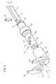
- the illustration Fig. 1shows a side view of a medical instrument 1, the power transmission mechanism can be used in many ways, such as for punching, scissors, needle holder, drum instruments and the like.
- the medical instrument 1 shownessentially consists of a hollow shaft 2, at the proximal end of which is arranged a handle 3 a that is pivotable about a pivot axis 4 and a handle portion 3 b which is pivotable about a pivot axis 4.
- a tool tip 6can be fixed by means of a coupling mechanism 5, which tool comprises a tool 7 which is shown in FIGS Fig. 2 and 3 illustrated first embodiment of a rigid jaw part 7a and a relative to the rigid jaw part 7a pivotable jaw part 7b consists.
- the tool 7consists of two mutually pivotable jaws 7b and 7c.
- the tool 7is formed so that the jaw parts 7a, 7b and 7c are angled perpendicular to the instrument longitudinal axis 8: Other angular positions of the jaws 7a, 7b and 7c of the tool 7 to the instrument longitudinal axis 8 between 0 ° and 90 ° and also above however, they are also practical.
- a pull / push rod 9is mounted in the hollow shaft 2, which is the distal side with the pivotable jaw part 7b or the pivotable jaw parts 7b and 7c in operative connection and which is connected at the proximal end with the pivotable handle part 3b of the handle 3 to pass through the Swiveling the grip part 3b to transfer the pivotable jaw part 7b or the pivotable jaw parts 7b and 7c from a closed position to an open position or vice versa.
- the dismantling of the medical instrument 1 in individual modular units, such as the tool tip 6 and the shaft 2,facilitates the assembly and disassembly of the medical instrument 1 for cleaning purposes and / or for changing the tool 7.
- the coupling mechanism 5, over which the tool tip 6 on the shaft 2 can be fixeddesigned as a bayonet connection.
- each pivotable jaw part 7b, 7crotationally connected to a proximally extending sleeve 10 which is rotatable about the instrument longitudinal axis 8, but fixed in the axial direction in the tool tip 6, wherein the pull / push rod 9 and each sleeve 10 for pivoting the pivotable jaw parts 7b, 7c via a pin-slot control 11 are in operative connection with each other.
- the pin-slot controller 11consists in the illustrated embodiments of two oppositely fixed to the pull / push rod 9 arranged control pin 12, which engage in each case formed in each sleeve 10 helical guide track 13.
- control pin 12engage in each case formed in each sleeve 10 helical guide track 13.
- the use of only one control pin 12 and a helical guideway 13is sufficient, but two control pins 12 provide better guidance of the pull / push rod 9 and a smooth movement of the motion conversion of the translational to the rotational movement.
- pin-slot controls 11designed as described above cause the control pin 12 of the pull / push rod 9 engaging in the helical guideways 13 in the axial direction to displace the sleeves 8 mounted in the tool tip 6 in the axial direction Turn instrument longitudinal axis 8, which in turn causes a pivoting of the sleeve 10 connected to the pivotable jaw parts 7b, 7c of the tool 7.
- the opening angle of the jaw parts 7a, 7b and 7ccan be predetermined to each other, so that depending on the application and required opening angle of the tool 7, a sleeve 10 with a corresponding helical pitch in the tool tip 6 of the medical instrument 1 can be used.
- the choice of the helical pitchalso plays a role in the force required to open the jaws 7b, 7c and at the speed with which the jaws 7b, 7c are opened. Furthermore, can be on the arrangement of the helical guideways 13 in the sleeve 10, namely from top to bottom from proximal to distal or vice versa, set whether the opening or closing of the handle 3, the pivotable jaw parts 7b, 7c are opened or closed.
- each sleeve 10with a lubricious coating on its outer jacket surface 10a adjacent to the inner side of the shank or inner side of the sheath.
- the inner side of the shank or inner side of the sheathit is also possible for the inner side of the shank or inner side of the sheath to have a lubricious coating on its inner circumferential surface lying against the sleeve 10.
- a sleeve made of a lubricious material between the componentsto be rotated relative to each other.
- a lubricious materialfor example, Teflon® or the like is advantageous.
- At least one flat 14is formed in the region of the coupling mechanism 5 formed as a bayonet connection on the pull / push rod 9, which has a corresponding contact surface 15 on the inside of the tool tip having the coupling mechanism 6 corresponds. In addition to the rotation, this guarantees at least one flat 14 on the pull / push rod 9 together with the corresponding contact surface 15 of the tool tip 6 an exact guidance of the pull / push rod 9 in the axial direction.
- the two in the pictures Fig. 2 and 3 as in Fig. 4 illustrated medical instruments 1differ from each other by the formation of the tools 7, namely in a tool 7 with a rigid jaw part 7a and a pivotable jaw part 7b according to Fig. 2 and 3 and in a tool 7 with two mutually pivotable jaws 7b and 7c according to Fig. 4 ,
- the rigid jaw part 7ais fixedly connected to the tool tip 6, while the pivotable jaw part 7b rotationally fixed to the sleeve 10 is connected, which is rotatably mounted in the tool tip 6 in the mounted state.
- the rotationally fixed connection of the sleeve 10 with the pivotable jaw part 7bfor example, by gluing or positive connection of the two components 7b and 10, wherein in the illustrated embodiment on the sleeve 10, a pin 16 is formed on the distal side in the assembled state in a corresponding receptacle 17th engaged in the pivotable jaw part 7b.
- the tool tip 6consists of two parts, a distal part 6a having the jaw parts 7a and 7b, and a proximal part 6b having the coupling mechanism 5.
- the two parts 6a and 6b of the tool tip 6are connected to each other, for example by welding.
- the pull / push rod 9is first pushed proximally through the proximal part 6b of the tool tip 6 until the pull / push rod 9 is received in the sleeve 10.
- the control pin 12is inserted into the pull / push rod 9, that the control pin 12 forming the pin-slot control 11 engages in the two formed in the sleeve 10 helical guideways 13.
- the pivotable jaw part 7bis inserted through a recess 18 in the tool tip 6 and the coupled with the pull / push rod 9 sleeve 10 inserted into the distal part 6a of the tool tip 6 until the pin 16 of the sleeve 10 in the receptacle 17 of the pivotable Jaw part 7b engages.
- the proximal part 6b and the distal part 6a of the tool tip 6are connected to one another and in the last step the tool tip 6 and the shaft 2 are coupled to one another via the bayonet connection.
- the tool 7consists of the two mutually pivotable jaw parts 7b and 7c, which are each connected to a rotatably mounted in the tool tip 6 sleeve 10, wherein the two sleeves 10 mounted in the assembled state coaxially with each other and rotatable against each other in the tool tip 6 are.
- the tool tip 6also consists of two parts, a distal part 6a having the jaw parts 7a and 7b and a proximal part 6b having the coupling mechanism 5.
- the two parts 6a and 6b of the tool tip 6are connected to each other for example by screwing.
- the pull / push rod 9is first pushed proximally through the proximal part 6b of the tool tip 6 until the pull / push rod 9 is received in the two coaxially telescoped sleeves 10.
- the control pin 12is inserted into the pull / push rod 9, that the control pin 12, the pin slot controller 11 forming, engages in each of the two formed in the sleeves 10 helical guideways 13.
- pivotable jaw parts 7b and 7care inserted via a recess 18 in the tool tip 6 and the coupled with the pull / push rod 9 sleeves 10 inserted into the distal part 6a of the tool tip 6 until the sleeves 10 against rotation with the pivotable jaw parts 7b and 7c are connected.
- the proximal part 6b and the distal part 6a of the tool tip 6are connected to one another and in the last step the tool tip 6 and the shaft 2 are coupled to one another via the bayonet connection.
- the thus formed medical instruments 1are characterized by the fact that the pure axial movement of the pull / push rod 9 is simply and easily dosed and substantially free of play converted into a rotational movement of the jaws 7b and 7c by the described pin-slot control 11.
Landscapes
- Health & Medical Sciences (AREA)
- Surgery (AREA)
- Life Sciences & Earth Sciences (AREA)
- Biomedical Technology (AREA)
- Medical Informatics (AREA)
- Veterinary Medicine (AREA)
- Public Health (AREA)
- Engineering & Computer Science (AREA)
- General Health & Medical Sciences (AREA)
- Heart & Thoracic Surgery (AREA)
- Nuclear Medicine, Radiotherapy & Molecular Imaging (AREA)
- Molecular Biology (AREA)
- Animal Behavior & Ethology (AREA)
- Orthopedic Medicine & Surgery (AREA)
- Dentistry (AREA)
- Oral & Maxillofacial Surgery (AREA)
- Ophthalmology & Optometry (AREA)
- Surgical Instruments (AREA)
Description
Translated fromGermanDie Erfindung betrifft ein medizinisches Instrument mit einem hohlen Schaft, an dessen proximalem Ende eine aus mindestens zwei Griffteilen bestehende Handhabe angeordnet ist und an dessen distalem Ende über einen Kupplungsmechanismus eine Werkzeugspitze festlegbar ist, die ein aus mindestens zwei Maulteilen bestehendes, quer zur Instrumentenlängsachse abgewinkeltes Werkzeug aufweist, wobei mindestens ein Maulteil des Werkzeugs zum Öffnen und Schließen über ein verstellbar ausgebildetes Griffteil der Handhabe gegenüber dem mindestens einen anderen Maulteil des Werkzeugs verschwenkbar ist und das mindestens eine verschwenkbare Maulteil und das entsprechende, zum Verschwenken des Maulteils dienende Griffteil der Handhabe über eine axial verschiebbar in dem hohlen Schaft gelagerte Zug-/Druckstange miteinander in Wirkverbindung stehen.The invention relates to a medical instrument with a hollow shaft, at the proximal end of which a handle consisting of at least two handle parts is arranged and at its distal end via a coupling mechanism, a tool tip can be fixed, which consists of at least two jaw parts, transversely to the instrument longitudinal axis angled tool wherein at least one jaw part of the tool for opening and closing via an adjustable handle portion of the handle against the at least one other jaw part of the tool is pivotable and the at least one pivotable jaw part and the corresponding, serving for pivoting of the jaw part handle part of the handle via an axial displaceable in the hollow shaft mounted pull / push rod are in operative connection with each other.
Gattungsgemäße medizinische Instrumente, bei denen das verschwenkbare Maulteil ausgehend von einem verschwenkbaren Griffteil der Handhabe über ein Zug-/Druckelement betätigbar ist, finden insbesondere in der endoskopischen Chirurgie vielseitige Verwendung, beispielsweise als Stanzen, Scheren, Nadelhalter, Fassinstrumente und dergleichen.Generic medical instruments in which the pivotable jaw part, starting from a pivotable handle part of the handle via a pull / push element is actuated, find in particular in endoscopic surgery versatile use, such as punching, scissors, needle holder, barrel instruments and the like.
Bei den medizinischen Instrumenten, bei denen die Maulteile des Werkzeugs seitlich zur Instrumentenlängsachse abgewinkelt ausgebildet sind, ist es notwendig, die über das Verschwenken der Handhabe initiierte Axialbewegung der Zug-/Druckstange in eine Drehbewegung umzusetzen. Hierzu ist es beispielsweise aus der
Eine vergleichbares medizinisches Instrument gemäß dem Oberbegriff ist weiterhin aus der
Davon ausgehend liegt der Erfindung dieAufgabe zugrunde, ein medizinisches Instrument der eingangs genannten Art so auszugestalten, dass die Umsetzung der Axialbewegung der Zug-/Druckstange in die Drehbewegung des verschwenkbaren Maulteils bei guter Kraftübertragung einfach und zuverlässig erfolgt und dabei reparaturfreundlich bzw. sterilisierungsfreundlich aufgebaut sein soll.Based on this, the invention has theobject , a medical instrument of the type mentioned in such a way that the implementation of the axial movement of the pull / push rod in the rotational movement of the pivotable jaw with good power transmission is simple and reliable, while being easy to repair or sterilization friendly should.
DieLösung dieser Aufgabenstellung ist erfindungsgemäß dadurch gekennzeichnet, dass jedes verschwenkbare Maulteil mit einer sich nach proximal erstreckenden Hülse verbunden ist, die um die Instrumentenlängsachse verdrehbar und in Axialrichtung fixiert in der Werkzeugspitze gelagert ist und, dass die Zug-/Druckstange und jede Hülse zum Verschwenken des betreffenden verschwenkbaren Maulteils über eine Zapfen-Schlitz-Steuerung in Wirkverbindung miteinander stehen.Thesolution to thisproblem is inventively characterized in that each pivotable jaw part is connected to a proximally extending sleeve which is mounted rotatable about the instrument longitudinal axis and fixed in the axial direction in the tool tip and that the pull / push rod and each sleeve for pivoting of the respective pivotable jaw part via a pin-slot control in operative connection with each other.
Durch die erfindungsgemäße Lagerung des mindestens einen verschwenkbaren Maulteils an einer verdrehbar in der Werkzeugspitze gelagerten Hülse, die ihrerseits über eine Zapfen-Schlitz-Steuerung mit der Zug-/Druckstange in Wirkverbindung steht, ist es auf konstruktiv einfache Weise möglich, die Axialbewegung der Zug-/Druckstange in eine Rotationsbewegung der Hülse und somit auch des verschwenkbaren Maulteils umzuwandeln.Due to the inventive bearing of the at least one pivotable jaw part on a rotatably mounted in the tool tip sleeve, which in turn is connected via a pin-slot control with the pull / push rod in operative connection, it is possible in a structurally simple manner, the axial movement of the train / Convert push rod into a rotational movement of the sleeve and thus also of the pivotable jaw part.
Um die Axialbewegung der Zug-/Druckstange möglichst spielfrei in eine Rotationsbewegung der Hülse umwandeln zu können, wird gemäß einer ersten Ausführungsform der Erfindung vorgeschlagen, dass die Zapfen-Schlitz-Steuerung aus mindestens einem ortsfest an der Zug-/Druckstange angeordneten Steuerzapfen besteht, der in eine in jeder Hülse ausgebildete wendelförmige Führungsbahn eingreift.In order to convert the axial movement of the pull / push rod as possible without play in a rotational movement of the sleeve, it is proposed according to a first embodiment of the invention that the pin-slot control consists of at least one stationary on the pull / push rod arranged control pin, the engages in a formed in each sleeve helical track.
Gemäß der Erfindung wird vorgeschlagen, einen Kopplungsmechanismus zwischen dem hohlen Schaft und der Werkzeugspitze vorzusehen und diesen als Bajonett-Verbindung auszubilden. Dieser als Bajonett-Verbindung ausgebildeter Kopplungsmechanismus zeichnet sich dadurch aus, dass er einfach zu handhaben und robust ist. Die durch den Kopplungsmechanismus bedingte Zerlegbarkeit des medizinischen Instruments in einzelne modulare Baueinheiten erleichtert die Montage und Demontage des Instruments zu Reinigungszwecken, zu Sterilisierungszwecken, zu Reparaturzwecken und/oder zum Wechseln des Werkzeugs.According to the invention, it is proposed to provide a coupling mechanism between the hollow shaft and the tool tip and to form this as a bayonet connection. This designed as a bayonet coupling mechanism is characterized in that it is easy to handle and robust. The disengageability of the medical instrument into individual modular units due to the coupling mechanism facilitates the assembly and disassembly of the instrument for cleaning purposes, for sterilization purposes, for repair purposes and / or for changing the tool.
Um die Zug-/Druckstange gegen Torsion zu sichern, wird mit der Erfindung weiterhin gemäß einer bevorzugten Ausbildung der Erfindung vorgeschlagen, dass im Bereich des Kopplungsmechanismus an der Zug-/Druckstange mindestens eine Abflachung ausgebildet ist, die mit einer entsprechenden Anlagefläche an der Innenseite des den Kopplungsmechanismus aufweisenden distalen Endes des Schaftes korrespondiert. Neben der Verdrehsicherung bewirkt diese mindestens eine Abflachung an der Zug-/Druckstange zusammen mit der korrespondierenden Anlagefläche der Werkzeugspitze eine exakte Führung der Zug-/Druckstange in Axialrichtung.In order to secure the pull / push rod against torsion, the invention further proposes according to a preferred embodiment of the invention that in the region of the coupling mechanism on the pull / push rod at least one flat is formed, which with a corresponding contact surface on the inside of the Corresponding to the coupling mechanism having distal end of the shaft. In addition to the rotation, this causes at least one flattening on the pull / push rod together with the corresponding contact surface of the tool tip exact guidance of the pull / push rod in the axial direction.
Gemäß einer bevorzugten Ausführungsform sind an der Zug-/Druckstange zwei einander gegenüberliegende Steuerzapfen angeordnet, die jeweils in eine in jeder Hülse ausgebildete wendelförmige Führungsbahn eingreifen, um eine gleichmäßige Führung der Zug-/Druckstange und einen gleichmäßigen Bewegungsablauf der Bewegungsumwandlung zu gewährleisten.According to a preferred embodiment, two opposing control pins are arranged on the pull / push rod, each engaging in a formed in each sleeve helical track to ensure uniform guidance of the pull / push rod and a smooth movement of the motion conversion.
Gemäß einer zweiten, alternativen erfindungsgemäßen Ausführungsform wird vorgeschlagen, dass die Zapfen-Schlitz-Steuerung aus einem ortsfest an jeder Hülse angeordneten Steuerzapfen besteht, der in jeweils eine in der Zug-/Druckstange ausgebildete wendelförmige Führungsbahn eingreift.According to a second, alternative embodiment of the invention it is proposed that the pin-slot control consists of a control pin which is fixedly arranged on each sleeve and which engages in each case in a helical guide track formed in the pull / push rod.
Um die Reibung zwischen der verdrehbar im Schaft gelagerten Hülse und der Schaftinnenseite oder zwischen zwei koaxial zueinander angeordneten Hülsen zu reduzieren wird erfindungsgemäß vorgeschlagen, dass jede Hülse auf ihrer an ihrer an einem anderen Bauteil anliegenden äußeren Mantelfläche eine gleitfähige Beschichtung aufweist. Alternativ ist es selbstverständlich auch möglich, dass die Schaftinnenseite bzw. Hülseninnenseite auf ihrer an der Hülse anliegenden inneren Mantelfläche eine gleitfähige Beschichtung aufweist. Desweiteren besteht die Möglichkeit, zwischen die relativ zueinander zu verdrehenden Bauteile eine Hülse aus einem gleitfähigen Material einzufügen. Als gleitfähiges Material ist beispielsweise Teflon ® oder dergleichen vorteilhaft.In order to reduce the friction between the sleeve rotatably mounted in the shaft and the shaft inner side or between two sleeves arranged coaxially with one another, it is proposed according to the invention that each sleeve has a lubricious coating on its outer jacket surface abutting on another component. Alternatively, it is of course also possible that the Shaft inside or sleeve inner side has on its sleeve adjacent to the inner circumferential surface a lubricious coating. Furthermore, it is possible to insert a sleeve made of a lubricious material between the components to be rotated relative to each other. As a lubricious material, for example, Teflon® or the like is advantageous.
Gemäß einer ersten praktischen Ausführungsform der Erfindung wird vorgeschlagen, dass ein Maulteil des Werkzeugs starr und das andere Maulteil des Werkzeugs verschwenkbar ausgebildet ist, wobei das starre Maulteil mit der Werkzeugspitze verbunden ist und das verschwenkbare Maulteil mit der verdrehbar in der Werkzeugspitze gelagerten Hülse verbunden ist. Bei dieser Ausführungsform bildet das beispielsweise einstückig mit der Werkzeugspitze ausgebildete starre Maulteil das distale Ende des erfindungsgemäßen medizinischen Instruments.According to a first practical embodiment of the invention it is proposed that a jaw part of the tool is rigid and the other jaw part of the tool is pivotable, wherein the rigid jaw part is connected to the tool tip and the pivotable jaw part is connected to the rotatably mounted in the tool tip sleeve. In this embodiment, the rigid jaw part, for example formed integrally with the tool tip, forms the distal end of the medical instrument according to the invention.
Gemäß einer zweiten Ausführungsform zur Ausbildung des Werkzeugs wird mit der Erfindung vorgeschlagen, dass beide Maulteile des Werkzeugs verschwenkbar ausgebildet sind, wobei jedes verschwenkbare Maulteil jeweils mit einer verdrehbar in der Werkzeugspitze gelagerten Hülse verbunden ist und die beiden Hülsen koaxial ineinander gelagert sind.According to a second embodiment for the formation of the tool is proposed with the invention that both jaws of the tool are designed to pivot, each pivotable jaw part is connected in each case with a rotatably mounted in the tool tip sleeve and the two sleeves are coaxially mounted one inside the other.
Schließlich wird mit der Erfindung vorgeschlagen, dass durch die Wahl der Steigung der wendelförmigen Führungsbahn der Öffnungswinkel der Maulteile zueinander vorgebbar ist, so dass je nach Anwendungsfall und erforderlichem Öffnungswinkel des Werkzeugs eine Hülse mit entsprechender Wendelsteigung in das erfindungsgemäße medizinische Instrument einsetzbar ist.Finally, it is proposed with the invention that the opening angle of the jaws to each other can be predetermined by the choice of the pitch of the helical guideway, so that depending on the application and required opening angle of the tool a sleeve with a corresponding helical pitch in the medical instrument according to the invention can be used.
Die Wendelsteigung spielt darüber hinaus eine Rolle beim Kraftaufwand, der benötigt wird, um die Maulteile zu öffnen sowie bei der Geschwindigkeit, mit der die Maulteile geöffnet werden. Desweiteren lässt sich über die Anordnung der wendelförmigen Führungsbahn in der Hülse, nämlich von oben nach unten von proximal nach distal oder umgekehrt, einstellen, ob beim Öffnen oder Schließen der Handhabe das verschwenkbare Maulteil geöffnet oder geschlossen wird.The spiral pitch also plays a role in the effort required to open the jaws and at the speed with which the jaws are opened. Furthermore, can be on the arrangement of the helical guideway in the sleeve, namely from top to bottom from proximal to distal or vice versa, set whether the pivoting jaw part is opened or closed when opening or closing the handle.
Um eine möglichst spielfreie Übertragung der Drehbewegung der mindestens einen verdrehbar in der Werkzeugspitze gelagerten Hülse auf das zugehörige verschwenkbare Maulteil zu bewirken, wird erfindungsgemäß vorgeschlagen, dass das verschwenkbare Maulteil und die Hülse, beispielsweise mittels Verkleben, verdrehfest miteinander verbunden sind.To a possible backlash-free transmission of the rotational movement of the at least one rotatably mounted in the tool tip sleeve on the associated pivotable To cause jaw, the invention proposes that the pivotable jaw part and the sleeve, for example by means of gluing, rotationally connected to each other.
Weitere Merkmale und Vorteile der Erfindung ergeben sich anhand der zugehörigen Zeichnungen, in denen zwei Ausführungsbeispiele eines erfindungsgemäßen medizinischen Instruments nur beispielhaft dargestellt sind, ohne die Erfindung auf diese Ausführungsbeispiele zu beschränken. In den Zeichnungen zeigt:
- Fig. 1
- eine schematische Seitenansicht eines erfindungsgemäßen medizinischen Instruments;
- Fig. 2
- eine perspektivische Explosionsdarstellung des Details II gemäß
Fig. 1 . eine erste erfindungsgemäße Ausführungsform von distal aus betrachtet darstellend; - Fig. 3
- eine teilweise montierte Darstellung des Instruments gemäß
Fig. 2 , von proximal aus betrachtet und - Fig. 4
- eine perspektivische Explosionsdarstellung des Details IV gemäß
Fig. 1 , eine zweite erfindungsgemäße Ausführungsform darstellend.
- Fig. 1
- a schematic side view of a medical instrument according to the invention;
- Fig. 2
- an exploded perspective view of the detail II according to
Fig. 1 , a first embodiment of the invention from distally viewed representing; - Fig. 3
- a partially assembled view of the instrument according to
Fig. 2 , viewed from the proximal and - Fig. 4
- an exploded perspective view of the detail IV according to
Fig. 1 FIG. 2 illustrates a second embodiment of the invention.
Die Abbildung
Das dargestellte medizinische Instrument 1 besteht im Wesentlichen aus einem hohlen Schaft 2, an dessen proximalem Ende eine aus einem starren Griffteil 3a und einem gegenüber dem starren Griffteil 3a um eine Schwenkachse 4 verschwenkbaren Griffteil 3b bestehende Handhabe 3 angeordnet ist. Am distalen Ende des Schaftes 2 ist über einen Kopplungsmechanismus 5 eine Werkzeugspitze 6 festlegbar, die ein Werkzeug 7 umfasst, welches beim in den Abbildungen
Bei den dargestellten Ausführungsformen ist das Werkzeug 7 so ausgebildet, dass die Maulteile 7a, 7b und 7c rechtwinklig zur Instrumentenlängsachse 8 abgewinkelt sind: Andere Winkellagen der Maulteile 7a, 7b und 7c des Werkzeugs 7 zur Instrumentenlängsachse 8 zwischen 0° und 90° und auch darüber hinaus sind jedoch auch praktikabel.In the illustrated embodiments, the
Wie weiterhin aus
Die Zerlegbarkeit des medizinischen Instruments 1 in einzelne modulare Baueinheiten, wie beispielsweise die Werkzeugspitze 6 und den Schaft 2, erleichtert die Montage und Demontage des medizinischen Instruments 1 zu Reinigungszwecken und/oder zum Wechseln des Werkzeugs 7. Bei den dargestellten Ausführungsbeispielen ist der Kopplungsmechanismus 5, über den die Werkzeugspitze 6 am Schaft 2 festlegbar ist, als Bajonett-Verbindung ausgebildet.The dismantling of the medical instrument 1 in individual modular units, such as the
Um die über die Betätigung des verschwenkbaren Griffteils 3b der Handhabe 3 auf die Zug-/Druckstange 9 übertragene, ausschließlich in Axialrichtung wirkende Verschiebung der Zug-/Druckstange 9 in eine Rotationsbewegung zum Verschwenken der verschwenkbaren Maulteile 7b, 7c des Werkzeugs 7 umwandeln zu können, ist jedes verschwenkbare Maulteil 7b, 7c verdrehfest mit einer sich nach proximal erstreckenden Hülse 10 verbunden, die um die Instrumentenlängsachse 8 verdrehbar, aber in Axialrichtung fixiert in der Werkzeugspitze 6 gelagert ist, wobei die Zug-/Druckstange 9 und jede Hülse 10 zum Verschwenken der verschwenkbaren Maulteile 7b, 7c über eine Zapfen-Schlitz-Steuerung 11 in Wirkverbindung miteinander stehen.In order to convert the actuation of the pivotable handle part 3b of the
Die Zapfen-Schlitz-Steuerung 11 besteht bei den dargestellten Ausführungsbeispielen aus zwei einander gegenüberliegend ortsfest an der Zug-/Druckstange 9 angeordneten Steuerzapfen 12, die in jeweils eine in jeder Hülse 10 ausgebildete wendelförmige Führungsbahn 13 eingreifen. Selbstverständlich ist auch die Verwendung nur eines Steuerzapfens 12 und einer wendelförmigen Führungsbahn 13 ausreichend, jedoch bieten zwei Steuerzapfen 12 eine bessere Führung der Zug-/Druckstange 9 und einen gleichmäßigen Bewegungsablauf der Bewegungsumwandlung von der translatorischen in die rotatorische Bewegung.The pin-
Alternativ zu der zuvor beschriebenen Ausgestaltung der Zapfen-Schlitz-Steuerung 10 ist es auch möglich, an der Hülse 10 einen ortsfesten Steuerzapfen 12 anzuordnen, der in jeweils eine in der Zug-/Druckstange 9 ausgebildete wendelförmige Führungsbahn 13 eingreift.As an alternative to the previously described embodiment of the pin-
Diese wie zuvor beschrieben ausgebildeten Zapfen-Schlitz-Steuerungen 11 bewirken, dass bei der Verschiebung der Zug-/Druckstange 9 in Axialrichtung die in die wendelförmigen Führungsbahnen 13 eingreifenden Steuerzapfen 12 der Zug-/Druckstange 9 die in der Werkzeugspitze 6 gelagerten Hülsen 8 um die Instrumentenlängsachse 8 verdrehen, was seinerseits ein Verschwenken des mit den Hülsen 10 verbundenen verschwenkbaren Maulteilen 7b, 7c des Werkzeugs 7 bewirkt.These pin-
Durch die Wahl der Steigung der wendelfömigen Führungsbahnen 13 ist der Öffnungswinkel der Maulteile 7a, 7b und 7c zueinander vorgebbar, so dass je nach Anwendungsfall und erforderlichem Öffnungswinkel des Werkzeugs 7 eine Hülse 10 mit entsprechender Wendelsteigung in die Werkzeugspitze 6 des medizinischen Instruments 1 einsetzbar ist.By selecting the pitch of the
Die Wahl der Wendelsteigung spielt darüber hinaus eine Rolle beim Kraftaufwand, der benötigt wird, um die Maulteile 7b , 7c zu öffnen sowie bei der Geschwindigkeit, mit der die Maulteile 7b, 7c geöffnet werden. Desweiteren lässt sich über die Anordnung der wendelförmigen Führungsbahnen 13 in der Hülse 10, nämlich von oben nach unten von proximal nach distal oder umgekehrt, einstellen, ob beim Öffnen oder Schließen der Handhabe 3 die verschwenkbaren Maulteile 7b, 7c geöffnet oder geschlossen werden.The choice of the helical pitch also plays a role in the force required to open the jaws 7b, 7c and at the speed with which the jaws 7b, 7c are opened. Furthermore, can be on the arrangement of the
Um die Reibung zwischen der verdrehbar im Schaft 2 gelagerten Hülse 10 und der Schaftinnenseite oder zwischen zwei koaxial ineinander gelagerten Hülsen 10 (
Um die Zug-/Druckstange 9 gegen Torsion zu sichern, ist im Bereich des als Bajonett-Verbindung ausgebildeten Kopplungsmechanismus 5 an der Zug-/Druckstange 9 mindestens eine Abflachung 14 ausgebildet, die mit einer entsprechenden Anlagefläche 15 an der Innenseite der den Kopplungsmechanismus aufweisenden Werkzeugspitze 6 korrespondiert. Neben der Verdrehsicherung gewährleistet diese mindestens eine Abflachung 14 an der Zug-/Druckstange 9 zusammen mit der korrespondierenden Anlagefläche 15 der Werkzeugspitze 6 eine exakte Führung der Zug-/Druckstange 9 in Axialrichtung.In order to secure the pull /
Die beiden in den Abbildungen
Bei der in
Bei der in
Zur Montage des in
Anschließend wird das verschwenkbare Maulteil 7b über eine Aussparung 18 in die Werkzeugspitze 6 eingesetzt und die mit der Zug-/Druckstange 9 gekoppelte Hülse 10 in den distalen Teil 6a der Werkzeugspitze 6 eingeschoben, bis der Zapfen 16 der Hülse 10 in die Aufnahme 17 des verschwenkbaren Maulteils 7b eingreift.Subsequently, the pivotable jaw part 7b is inserted through a
Im nachfolgenden Montageschritt werden der proximale Teil 6b und der distale Teil 6a der Werkzeugspitze 6 miteinander verbunden und im letzten Schritt dann die Werkzeugspitze 6 und der Schaft 2 über die Bajonett-Verbindung miteinander gekoppelt.In the subsequent assembly step, the
Bei der in
Das drehfeste Verbinden der Hülsen 10 mit dem verschwenkbaren Maulteilen 7b und 7c erfolgt beispielsweise durch Verkleben oder formschlüssigen Verbinden der beiden Bauteile 7b und 10 bzw. 7c und 10.The rotationally fixed connection of the
Bei der in
Zur Montage des in
Anschließend werden die verschwenkbaren Maulteile 7b und 7c über eine Aussparung 18 in die Werkzeugspitze 6 eingesetzt und die mit der Zug-/Druckstange 9 gekoppelten Hülsen 10 in den distalen Teil 6a der Werkzeugspitze 6 eingeschoben, bis die Hülsen 10 verdrehfest mit den verschwenkbaren Maulteilen 7b und 7c verbunden sind.Subsequently, the pivotable jaw parts 7b and 7c are inserted via a
Im nachfolgenden Montageschritt werden der proximale Teil 6b und der distale Teil 6a der Werkzeugspitze 6 miteinander verbunden und im letzten Schritt dann die Werkzeugspitze 6 und der Schaft 2 über die Bajonett-Verbindung miteinander gekoppelt.In the subsequent assembly step, the
Die solchermaßen ausgebildeten medizinischen Instrumente 1 zeichnen sich dadurch aus, dass durch die beschriebenen Zapfen-Schlitz-Steuerung 11 die reine Axialbewegung der Zug-/Druckstange 9 einfach und gut dosierbar sowie im Wesentlichen spielfrei in eine Rotationsbewegung der Maulteile 7b und 7c umgesetzt wird.The thus formed medical instruments 1 are characterized by the fact that the pure axial movement of the pull /
Claims (11)
- Medical instrument with a hollow shaft (2), at the proximal end of which a handle (3) consisting of at least two grip parts (3a, 3b) is arranged and at the distal end of which a tool tip (6) can be fixed, the tool tip having a tool (7) which consists of at least two jaw parts (7a, 7b) and is angled transversely with respect to the longitudinal axis (8) of the instrument, wherein at least one jaw part (7b) of the tool (7) can be pivoted with respect to the at least one other jaw part (7a) of the tool (7) for opening and closing by way of an adjustably designed grip part (3b) of the handle (3), and the at least one pivotable jaw part (7b) and the corresponding grip part (3b) of the handle (3) which serves to pivot the jaw part (7b) are operatively connected to one another by way of a pull/push rod (9) mounted in an axially displaceable manner in the hollow shaft (2), wherein each pivotable jaw part (7b) is connected to a sleeve (10), which extends towards the proximal end and which is mounted in the tool tip (6) such that it can be twisted about the longitudinal axis (8) of the instrument and is fixed in the axial direction, and wherein the pull/push rod (9) and each sleeve (10) are operatively connected to one another to pivot the relevant pivotable jaw part (7b) by way of a pin-and-slot control (11),
characterized
in that a tool tip (6) can be fixed to the distal end of the hollow shaft (2) by way of a coupling mechanism (5),
andin that the coupling mechanism (5), by way of which the tool tip (6) can be fixed to the shaft (2), is in the form of a bayonet connection. - Medical instrument according to Claim 1,characterized in that at least one flattened portion (14) is formed on the pull/push rod (9) in the region of the coupling mechanism (5), and corresponds to a corresponding contact surface (15) on the inner side of the tool tip (6) having the coupling mechanism (5), in order to secure the pull/push rod (9) against torsion.
- Medical instrument according to Claim 1 or 2,characterized in that the pin-and-slot control (11) consists of at least one control pin (12), which is arranged fixed in position on the pull/push rod (9) and engages into a helical guideway (13) formed in each sleeve (10).
- Medical instrument according to Claim 3,characterized in that two control pins (12) which lie opposite one another and each engage into a helical guideway (13) formed in each sleeve (10) are arranged on the pull/push rod (9).
- Medical instrument according to Claim 1 or 2,characterized in that the pin-and-slot control (11) consists of a control pin (12), which is arranged fixed in position on each sleeve (10) and engages into in each case one helical guideway (13) formed in the pull/push rod (9).
- Medical instrument according to one of Claims 1 to 5,characterized in that each sleeve (10) mounted in the tool tip (6) such that it can be twisted has a coating with slip properties on the outer lateral surface (10a) thereof which bears against another component (6 or 10).
- Medical instrument according to one of Claims 1 to 6,characterized in that one jaw part (7a) of the tool (7) is formed so as to be rigid and the other jaw part (7b) of the tool (7) is formed so as to be pivotable, wherein the rigid jaw part (7a) is connected to the tool tip (6) and the pivotable jaw part (7b) is connected to the sleeve (10) mounted in the tool tip (6) such that it can be twisted.
- Medical instrument according to one of Claims 1 to 6,characterized in that both jaw parts (7b, 7c) of the tool (7) are formed so as to be pivotable, wherein each pivotable jaw part (7b, 7c) is connected in each case to a sleeve (10) mounted in the tool tip (6) such that it can be twisted, and the two sleeves (10) are mounted coaxially one inside the other.
- Medical instrument according to one of Claims 3 to 8,characterized in that the opening angle of the jaw parts (7a, 7b) in relation to one another can be predetermined by the selection of the pitch of the helical guideway (13).
- Medical instrument according to one of Claims 1 to 9,characterized in that the at least one pivotable jaw part (7b) and the associated sleeve (10) are connected to one another such that they cannot twist.
- Medical instrument according to Claim 10,characterized in that the at least one pivotable jaw part (7b) and the associated sleeve (10) are adhesively bonded to one another.
Applications Claiming Priority (2)
| Application Number | Priority Date | Filing Date | Title |
|---|---|---|---|
| DE102009011205ADE102009011205A1 (en) | 2009-03-04 | 2009-03-04 | Medical instrument |
| PCT/EP2010/001281WO2010099930A1 (en) | 2009-03-04 | 2010-03-02 | Medical instrument |
Publications (2)
| Publication Number | Publication Date |
|---|---|
| EP2403418A1 EP2403418A1 (en) | 2012-01-11 |
| EP2403418B1true EP2403418B1 (en) | 2013-05-08 |
Family
ID=42227727
Family Applications (1)
| Application Number | Title | Priority Date | Filing Date |
|---|---|---|---|
| EP10711835.8AActiveEP2403418B1 (en) | 2009-03-04 | 2010-03-02 | Medical instrument |
Country Status (3)
| Country | Link |
|---|---|
| EP (1) | EP2403418B1 (en) |
| DE (1) | DE102009011205A1 (en) |
| WO (1) | WO2010099930A1 (en) |
Families Citing this family (2)
| Publication number | Priority date | Publication date | Assignee | Title |
|---|---|---|---|---|
| JP7569840B2 (en)* | 2019-08-14 | 2024-10-18 | エルエスアイ ソルーションズ インコーポレーテッド | Device for blood vessel harvesting |
| DE102020119462A1 (en) | 2020-07-23 | 2022-01-27 | Karl Storz Se & Co. Kg | MEDICAL INSTRUMENT |
Family Cites Families (6)
| Publication number | Priority date | Publication date | Assignee | Title |
|---|---|---|---|---|
| ATE131370T1 (en)* | 1989-08-16 | 1995-12-15 | Raychem Corp | ARRANGEMENT FOR GRABING OR CUTTING AN OBJECT |
| DE4307539B4 (en)* | 1993-03-10 | 2005-08-25 | Karl Storz Gmbh & Co. Kg | Medical forceps |
| DE9317535U1 (en)* | 1993-11-16 | 1994-01-27 | Tontarra Medizintechnik GmbH, 78573 Wurmlingen | Surgical tubular shaft instrument |
| DE10327655A1 (en) | 2003-06-20 | 2005-01-27 | Karl Storz Gmbh & Co. Kg | Medical instrument |
| DE102005021234A1 (en)* | 2005-05-09 | 2006-11-16 | Karl Storz Gmbh & Co. Kg | Medical instrument |
| DE102006040529A1 (en)* | 2006-08-30 | 2008-03-13 | Paul Peschke Gmbh | Surgical grasping forceps |
- 2009
- 2009-03-04DEDE102009011205Apatent/DE102009011205A1/ennot_activeWithdrawn
- 2010
- 2010-03-02WOPCT/EP2010/001281patent/WO2010099930A1/enactiveApplication Filing
- 2010-03-02EPEP10711835.8Apatent/EP2403418B1/enactiveActive
Also Published As
| Publication number | Publication date |
|---|---|
| DE102009011205A1 (en) | 2010-09-09 |
| WO2010099930A1 (en) | 2010-09-10 |
| EP2403418A1 (en) | 2012-01-11 |
Similar Documents
| Publication | Publication Date | Title |
|---|---|---|
| EP1464289B1 (en) | Surgical instrument, in which movements of the head and of the effector are decoupled | |
| EP1484024B1 (en) | Surgical instrument with handgrip and zero setting arrangment | |
| EP1464290B1 (en) | Surgical instrument | |
| DE10314828B3 (en) | Surgical instrument for minimal invasive surgery with movement compensation element for compensation of rotation of effector upon pivot movement of instrument head | |
| EP3020346B1 (en) | Medical instrument | |
| DE102008015418A1 (en) | Medical instrument | |
| EP1721577B1 (en) | Endoscopic instrument | |
| EP1235522A1 (en) | Surgical instrument for minimally invasive surgical interventions | |
| WO2014006186A1 (en) | Medical instrument, and method for pivoting such a medical instrument | |
| EP2561816A1 (en) | Tool for a micro-invasive surgical instrument | |
| EP3175802B1 (en) | Medical instrument | |
| EP1488749B1 (en) | Medical instrument | |
| WO2011063892A1 (en) | Surgical forceps having engagement in a groove | |
| DE10060769C2 (en) | Medical instrument | |
| DE102014117393A1 (en) | Turnable and bendable medical instrument | |
| EP2403418B1 (en) | Medical instrument | |
| DE102011088003A1 (en) | Medical instrument | |
| EP3695793B1 (en) | Medical instrument | |
| EP1365691B1 (en) | Medical instrument | |
| DE102014203168A1 (en) | Instrument for performing medical interventions | |
| EP1927320A2 (en) | Medical instrument | |
| EP3695790B1 (en) | Medical instrument | |
| DE202007000427U1 (en) | Surgical handle and surgical instrument | |
| EP2468193B1 (en) | Medical needle holder | |
| DE102011083331A1 (en) | gripping instrument |
Legal Events
| Date | Code | Title | Description |
|---|---|---|---|
| PUAI | Public reference made under article 153(3) epc to a published international application that has entered the european phase | Free format text:ORIGINAL CODE: 0009012 | |
| 17P | Request for examination filed | Effective date:20110726 | |
| AK | Designated contracting states | Kind code of ref document:A1 Designated state(s):AT BE BG CH CY CZ DE DK EE ES FI FR GB GR HR HU IE IS IT LI LT LU LV MC MK MT NL NO PL PT RO SE SI SK SM TR | |
| DAX | Request for extension of the european patent (deleted) | ||
| REG | Reference to a national code | Ref country code:DE Ref legal event code:R079 Ref document number:502010003279 Country of ref document:DE Free format text:PREVIOUS MAIN CLASS: A61B0017295000 Ipc:A61B0017160000 | |
| GRAP | Despatch of communication of intention to grant a patent | Free format text:ORIGINAL CODE: EPIDOSNIGR1 | |
| RIC1 | Information provided on ipc code assigned before grant | Ipc:A61B 17/16 20060101AFI20120921BHEP Ipc:A61B 17/32 20060101ALI20120921BHEP | |
| GRAS | Grant fee paid | Free format text:ORIGINAL CODE: EPIDOSNIGR3 | |
| GRAA | (expected) grant | Free format text:ORIGINAL CODE: 0009210 | |
| AK | Designated contracting states | Kind code of ref document:B1 Designated state(s):AT BE BG CH CY CZ DE DK EE ES FI FR GB GR HR HU IE IS IT LI LT LU LV MC MK MT NL NO PL PT RO SE SI SK SM TR | |
| REG | Reference to a national code | Ref country code:GB Ref legal event code:FG4D Free format text:NOT ENGLISH | |
| REG | Reference to a national code | Ref country code:AT Ref legal event code:REF Ref document number:610670 Country of ref document:AT Kind code of ref document:T Effective date:20130515 Ref country code:CH Ref legal event code:EP | |
| REG | Reference to a national code | Ref country code:IE Ref legal event code:FG4D Free format text:LANGUAGE OF EP DOCUMENT: GERMAN | |
| REG | Reference to a national code | Ref country code:DE Ref legal event code:R096 Ref document number:502010003279 Country of ref document:DE Effective date:20130711 | |
| REG | Reference to a national code | Ref country code:LT Ref legal event code:MG4D | |
| REG | Reference to a national code | Ref country code:NL Ref legal event code:VDEP Effective date:20130508 | |
| PG25 | Lapsed in a contracting state [announced via postgrant information from national office to epo] | Ref country code:FI Free format text:LAPSE BECAUSE OF FAILURE TO SUBMIT A TRANSLATION OF THE DESCRIPTION OR TO PAY THE FEE WITHIN THE PRESCRIBED TIME-LIMIT Effective date:20130508 Ref country code:NO Free format text:LAPSE BECAUSE OF FAILURE TO SUBMIT A TRANSLATION OF THE DESCRIPTION OR TO PAY THE FEE WITHIN THE PRESCRIBED TIME-LIMIT Effective date:20130808 Ref country code:ES Free format text:LAPSE BECAUSE OF FAILURE TO SUBMIT A TRANSLATION OF THE DESCRIPTION OR TO PAY THE FEE WITHIN THE PRESCRIBED TIME-LIMIT Effective date:20130819 Ref country code:SE Free format text:LAPSE BECAUSE OF FAILURE TO SUBMIT A TRANSLATION OF THE DESCRIPTION OR TO PAY THE FEE WITHIN THE PRESCRIBED TIME-LIMIT Effective date:20130508 Ref country code:GR Free format text:LAPSE BECAUSE OF FAILURE TO SUBMIT A TRANSLATION OF THE DESCRIPTION OR TO PAY THE FEE WITHIN THE PRESCRIBED TIME-LIMIT Effective date:20130809 Ref country code:LT Free format text:LAPSE BECAUSE OF FAILURE TO SUBMIT A TRANSLATION OF THE DESCRIPTION OR TO PAY THE FEE WITHIN THE PRESCRIBED TIME-LIMIT Effective date:20130508 Ref country code:PT Free format text:LAPSE BECAUSE OF FAILURE TO SUBMIT A TRANSLATION OF THE DESCRIPTION OR TO PAY THE FEE WITHIN THE PRESCRIBED TIME-LIMIT Effective date:20130909 Ref country code:SI Free format text:LAPSE BECAUSE OF FAILURE TO SUBMIT A TRANSLATION OF THE DESCRIPTION OR TO PAY THE FEE WITHIN THE PRESCRIBED TIME-LIMIT Effective date:20130508 Ref country code:IS Free format text:LAPSE BECAUSE OF FAILURE TO SUBMIT A TRANSLATION OF THE DESCRIPTION OR TO PAY THE FEE WITHIN THE PRESCRIBED TIME-LIMIT Effective date:20130908 | |
| PG25 | Lapsed in a contracting state [announced via postgrant information from national office to epo] | Ref country code:CY Free format text:LAPSE BECAUSE OF FAILURE TO SUBMIT A TRANSLATION OF THE DESCRIPTION OR TO PAY THE FEE WITHIN THE PRESCRIBED TIME-LIMIT Effective date:20130508 Ref country code:HR Free format text:LAPSE BECAUSE OF FAILURE TO SUBMIT A TRANSLATION OF THE DESCRIPTION OR TO PAY THE FEE WITHIN THE PRESCRIBED TIME-LIMIT Effective date:20130508 Ref country code:PL Free format text:LAPSE BECAUSE OF FAILURE TO SUBMIT A TRANSLATION OF THE DESCRIPTION OR TO PAY THE FEE WITHIN THE PRESCRIBED TIME-LIMIT Effective date:20130508 Ref country code:BG Free format text:LAPSE BECAUSE OF FAILURE TO SUBMIT A TRANSLATION OF THE DESCRIPTION OR TO PAY THE FEE WITHIN THE PRESCRIBED TIME-LIMIT Effective date:20130808 | |
| PG25 | Lapsed in a contracting state [announced via postgrant information from national office to epo] | Ref country code:LV Free format text:LAPSE BECAUSE OF FAILURE TO SUBMIT A TRANSLATION OF THE DESCRIPTION OR TO PAY THE FEE WITHIN THE PRESCRIBED TIME-LIMIT Effective date:20130508 | |
| PG25 | Lapsed in a contracting state [announced via postgrant information from national office to epo] | Ref country code:DK Free format text:LAPSE BECAUSE OF FAILURE TO SUBMIT A TRANSLATION OF THE DESCRIPTION OR TO PAY THE FEE WITHIN THE PRESCRIBED TIME-LIMIT Effective date:20130508 Ref country code:CZ Free format text:LAPSE BECAUSE OF FAILURE TO SUBMIT A TRANSLATION OF THE DESCRIPTION OR TO PAY THE FEE WITHIN THE PRESCRIBED TIME-LIMIT Effective date:20130508 Ref country code:SK Free format text:LAPSE BECAUSE OF FAILURE TO SUBMIT A TRANSLATION OF THE DESCRIPTION OR TO PAY THE FEE WITHIN THE PRESCRIBED TIME-LIMIT Effective date:20130508 Ref country code:EE Free format text:LAPSE BECAUSE OF FAILURE TO SUBMIT A TRANSLATION OF THE DESCRIPTION OR TO PAY THE FEE WITHIN THE PRESCRIBED TIME-LIMIT Effective date:20130508 | |
| PG25 | Lapsed in a contracting state [announced via postgrant information from national office to epo] | Ref country code:RO Free format text:LAPSE BECAUSE OF FAILURE TO SUBMIT A TRANSLATION OF THE DESCRIPTION OR TO PAY THE FEE WITHIN THE PRESCRIBED TIME-LIMIT Effective date:20130508 Ref country code:NL Free format text:LAPSE BECAUSE OF FAILURE TO SUBMIT A TRANSLATION OF THE DESCRIPTION OR TO PAY THE FEE WITHIN THE PRESCRIBED TIME-LIMIT Effective date:20130508 | |
| PLBE | No opposition filed within time limit | Free format text:ORIGINAL CODE: 0009261 | |
| STAA | Information on the status of an ep patent application or granted ep patent | Free format text:STATUS: NO OPPOSITION FILED WITHIN TIME LIMIT | |
| 26N | No opposition filed | Effective date:20140211 | |
| REG | Reference to a national code | Ref country code:DE Ref legal event code:R097 Ref document number:502010003279 Country of ref document:DE Effective date:20140211 | |
| PG25 | Lapsed in a contracting state [announced via postgrant information from national office to epo] | Ref country code:LU Free format text:LAPSE BECAUSE OF FAILURE TO SUBMIT A TRANSLATION OF THE DESCRIPTION OR TO PAY THE FEE WITHIN THE PRESCRIBED TIME-LIMIT Effective date:20140302 | |
| REG | Reference to a national code | Ref country code:CH Ref legal event code:PL | |
| REG | Reference to a national code | Ref country code:IE Ref legal event code:MM4A | |
| PG25 | Lapsed in a contracting state [announced via postgrant information from national office to epo] | Ref country code:IE Free format text:LAPSE BECAUSE OF NON-PAYMENT OF DUE FEES Effective date:20140302 Ref country code:CH Free format text:LAPSE BECAUSE OF NON-PAYMENT OF DUE FEES Effective date:20140331 Ref country code:LI Free format text:LAPSE BECAUSE OF NON-PAYMENT OF DUE FEES Effective date:20140331 | |
| REG | Reference to a national code | Ref country code:FR Ref legal event code:PLFP Year of fee payment:7 | |
| PG25 | Lapsed in a contracting state [announced via postgrant information from national office to epo] | Ref country code:MT Free format text:LAPSE BECAUSE OF FAILURE TO SUBMIT A TRANSLATION OF THE DESCRIPTION OR TO PAY THE FEE WITHIN THE PRESCRIBED TIME-LIMIT Effective date:20130508 | |
| PG25 | Lapsed in a contracting state [announced via postgrant information from national office to epo] | Ref country code:SM Free format text:LAPSE BECAUSE OF FAILURE TO SUBMIT A TRANSLATION OF THE DESCRIPTION OR TO PAY THE FEE WITHIN THE PRESCRIBED TIME-LIMIT Effective date:20130508 | |
| REG | Reference to a national code | Ref country code:AT Ref legal event code:MM01 Ref document number:610670 Country of ref document:AT Kind code of ref document:T Effective date:20150302 | |
| PG25 | Lapsed in a contracting state [announced via postgrant information from national office to epo] | Ref country code:MC Free format text:LAPSE BECAUSE OF FAILURE TO SUBMIT A TRANSLATION OF THE DESCRIPTION OR TO PAY THE FEE WITHIN THE PRESCRIBED TIME-LIMIT Effective date:20130508 | |
| PG25 | Lapsed in a contracting state [announced via postgrant information from national office to epo] | Ref country code:HU Free format text:LAPSE BECAUSE OF FAILURE TO SUBMIT A TRANSLATION OF THE DESCRIPTION OR TO PAY THE FEE WITHIN THE PRESCRIBED TIME-LIMIT; INVALID AB INITIO Effective date:20100302 Ref country code:TR Free format text:LAPSE BECAUSE OF FAILURE TO SUBMIT A TRANSLATION OF THE DESCRIPTION OR TO PAY THE FEE WITHIN THE PRESCRIBED TIME-LIMIT Effective date:20130508 | |
| PG25 | Lapsed in a contracting state [announced via postgrant information from national office to epo] | Ref country code:AT Free format text:LAPSE BECAUSE OF NON-PAYMENT OF DUE FEES Effective date:20150302 | |
| REG | Reference to a national code | Ref country code:FR Ref legal event code:PLFP Year of fee payment:8 | |
| PG25 | Lapsed in a contracting state [announced via postgrant information from national office to epo] | Ref country code:BE Free format text:LAPSE BECAUSE OF NON-PAYMENT OF DUE FEES Effective date:20140331 | |
| REG | Reference to a national code | Ref country code:DE Ref legal event code:R081 Ref document number:502010003279 Country of ref document:DE Owner name:KARL STORZ SE & CO. KG INTELLECTUAL PROPERTY, DE Free format text:FORMER OWNER: KARL STORZ GMBH & CO. KG, 78532 TUTTLINGEN, DE Ref country code:DE Ref legal event code:R081 Ref document number:502010003279 Country of ref document:DE Owner name:KARL STORZ SE & CO. KG, DE Free format text:FORMER OWNER: KARL STORZ GMBH & CO. KG, 78532 TUTTLINGEN, DE | |
| REG | Reference to a national code | Ref country code:FR Ref legal event code:PLFP Year of fee payment:9 | |
| PGFP | Annual fee paid to national office [announced via postgrant information from national office to epo] | Ref country code:IT Payment date:20180219 Year of fee payment:9 | |
| PG25 | Lapsed in a contracting state [announced via postgrant information from national office to epo] | Ref country code:MK Free format text:LAPSE BECAUSE OF FAILURE TO SUBMIT A TRANSLATION OF THE DESCRIPTION OR TO PAY THE FEE WITHIN THE PRESCRIBED TIME-LIMIT Effective date:20130508 | |
| PG25 | Lapsed in a contracting state [announced via postgrant information from national office to epo] | Ref country code:IT Free format text:LAPSE BECAUSE OF NON-PAYMENT OF DUE FEES Effective date:20190302 | |
| P01 | Opt-out of the competence of the unified patent court (upc) registered | Effective date:20230527 | |
| PGFP | Annual fee paid to national office [announced via postgrant information from national office to epo] | Ref country code:GB Payment date:20240319 Year of fee payment:15 | |
| PGFP | Annual fee paid to national office [announced via postgrant information from national office to epo] | Ref country code:FR Payment date:20240326 Year of fee payment:15 | |
| PGFP | Annual fee paid to national office [announced via postgrant information from national office to epo] | Ref country code:DE Payment date:20250327 Year of fee payment:16 |