EP2400924B1 - Prosthetic heart valve - Google Patents
Prosthetic heart valveDownload PDFInfo
- Publication number
- EP2400924B1 EP2400924B1EP10707703.4AEP10707703AEP2400924B1EP 2400924 B1EP2400924 B1EP 2400924B1EP 10707703 AEP10707703 AEP 10707703AEP 2400924 B1EP2400924 B1EP 2400924B1
- Authority
- EP
- European Patent Office
- Prior art keywords
- stent
- support
- cells
- post
- proximal
- Prior art date
- Legal status (The legal status is an assumption and is not a legal conclusion. Google has not performed a legal analysis and makes no representation as to the accuracy of the status listed.)
- Revoked
Links
- 210000003709heart valveAnatomy0.000titleclaimsdescription35
- 230000002787reinforcementEffects0.000claimsdescription33
- 125000006850spacer groupChemical group0.000claimsdescription16
- 238000013461designMethods0.000description14
- 239000000463materialSubstances0.000description14
- 210000000709aortaAnatomy0.000description13
- 238000003491arrayMethods0.000description13
- 210000001519tissueAnatomy0.000description12
- 238000004873anchoringMethods0.000description10
- 230000006870functionEffects0.000description9
- 230000007704transitionEffects0.000description9
- 210000003484anatomyAnatomy0.000description8
- 230000008859changeEffects0.000description6
- 230000007246mechanismEffects0.000description6
- 230000002966stenotic effectEffects0.000description6
- 230000008878couplingEffects0.000description5
- 238000010168coupling processMethods0.000description5
- 238000005859coupling reactionMethods0.000description5
- 230000033001locomotionEffects0.000description5
- 210000001015abdomenAnatomy0.000description4
- 230000002411adverseEffects0.000description4
- WYTGDNHDOZPMIW-RCBQFDQVSA-NalstonineNatural productsC1=CC2=C3C=CC=CC3=NC2=C2N1C[C@H]1[C@H](C)OC=C(C(=O)OC)[C@H]1C2WYTGDNHDOZPMIW-RCBQFDQVSA-N0.000description4
- 210000002376aorta thoracicAnatomy0.000description4
- 210000001765aortic valveAnatomy0.000description4
- 210000004351coronary vesselAnatomy0.000description4
- 229910003460diamondInorganic materials0.000description4
- 239000010432diamondSubstances0.000description4
- 230000009467reductionEffects0.000description4
- 210000001367arteryAnatomy0.000description3
- 230000015572biosynthetic processEffects0.000description3
- 239000008280bloodSubstances0.000description3
- 210000004369bloodAnatomy0.000description3
- 230000006835compressionEffects0.000description3
- 238000007906compressionMethods0.000description3
- 239000004744fabricSubstances0.000description3
- 238000005755formation reactionMethods0.000description3
- 238000005304joiningMethods0.000description3
- 238000000034methodMethods0.000description3
- 230000005012migrationEffects0.000description3
- 238000013508migrationMethods0.000description3
- HLXZNVUGXRDIFK-UHFFFAOYSA-Nnickel titaniumChemical compound[Ti].[Ti].[Ti].[Ti].[Ti].[Ti].[Ti].[Ti].[Ti].[Ti].[Ti].[Ni].[Ni].[Ni].[Ni].[Ni].[Ni].[Ni].[Ni].[Ni].[Ni].[Ni].[Ni].[Ni].[Ni]HLXZNVUGXRDIFK-UHFFFAOYSA-N0.000description3
- 229910001000nickel titaniumInorganic materials0.000description3
- 230000035479physiological effects, processes and functionsEffects0.000description3
- 239000007787solidSubstances0.000description3
- PXHVJJICTQNCMI-UHFFFAOYSA-NNickelChemical compound[Ni]PXHVJJICTQNCMI-UHFFFAOYSA-N0.000description2
- 239000004696Poly ether ether ketoneSubstances0.000description2
- 238000010009beatingMethods0.000description2
- 229920001222biopolymerPolymers0.000description2
- 238000002788crimpingMethods0.000description2
- 230000001351cycling effectEffects0.000description2
- 230000007423decreaseEffects0.000description2
- 230000023753dehiscenceEffects0.000description2
- 201000010099diseaseDiseases0.000description2
- 208000037265diseases, disorders, signs and symptomsDiseases0.000description2
- 230000000694effectsEffects0.000description2
- 238000002513implantationMethods0.000description2
- 238000010348incorporationMethods0.000description2
- 238000011835investigationMethods0.000description2
- 229910052751metalInorganic materials0.000description2
- 239000002184metalSubstances0.000description2
- 150000002739metalsChemical class0.000description2
- 229920002530polyetherether ketonePolymers0.000description2
- 238000004904shorteningMethods0.000description2
- 229910001220stainless steelInorganic materials0.000description2
- 239000010935stainless steelSubstances0.000description2
- 229920001059synthetic polymerPolymers0.000description2
- VYZAMTAEIAYCRO-UHFFFAOYSA-NChromiumChemical compound[Cr]VYZAMTAEIAYCRO-UHFFFAOYSA-N0.000description1
- 102000008186CollagenHuman genes0.000description1
- 108010035532CollagenProteins0.000description1
- 102000016942ElastinHuman genes0.000description1
- 108010014258ElastinProteins0.000description1
- 239000004952PolyamideSubstances0.000description1
- RTAQQCXQSZGOHL-UHFFFAOYSA-NTitaniumChemical compound[Ti]RTAQQCXQSZGOHL-UHFFFAOYSA-N0.000description1
- 238000005299abrasionMethods0.000description1
- 229920006397acrylic thermoplasticPolymers0.000description1
- 229910045601alloyInorganic materials0.000description1
- 239000000956alloySubstances0.000description1
- 238000004458analytical methodMethods0.000description1
- 201000002064aortic valve insufficiencyDiseases0.000description1
- 229920003235aromatic polyamidePolymers0.000description1
- 238000005452bendingMethods0.000description1
- 230000008901benefitEffects0.000description1
- 210000004763bicuspidAnatomy0.000description1
- 239000000560biocompatible materialSubstances0.000description1
- 230000017531blood circulationEffects0.000description1
- 230000002308calcificationEffects0.000description1
- 238000007675cardiac surgeryMethods0.000description1
- 238000013130cardiovascular surgeryMethods0.000description1
- 230000010261cell growthEffects0.000description1
- 229910052804chromiumInorganic materials0.000description1
- 239000011651chromiumSubstances0.000description1
- 229910017052cobaltInorganic materials0.000description1
- 239000010941cobaltSubstances0.000description1
- GUTLYIVDDKVIGB-UHFFFAOYSA-Ncobalt atomChemical compound[Co]GUTLYIVDDKVIGB-UHFFFAOYSA-N0.000description1
- 229920001436collagenPolymers0.000description1
- 239000002131composite materialSubstances0.000description1
- 238000007796conventional methodMethods0.000description1
- 230000001419dependent effectEffects0.000description1
- 230000003205diastolic effectEffects0.000description1
- 238000003618dip coatingMethods0.000description1
- 238000002224dissectionMethods0.000description1
- 238000009826distributionMethods0.000description1
- 229920002549elastinPolymers0.000description1
- 230000002708enhancing effectEffects0.000description1
- 230000036541healthEffects0.000description1
- 210000005003heart tissueAnatomy0.000description1
- 239000007943implantSubstances0.000description1
- 238000000338in vitroMethods0.000description1
- 238000007373indentationMethods0.000description1
- 210000005240left ventricleAnatomy0.000description1
- 238000004519manufacturing processMethods0.000description1
- 210000004115mitral valveAnatomy0.000description1
- 239000000203mixtureSubstances0.000description1
- 238000012986modificationMethods0.000description1
- 230000004048modificationEffects0.000description1
- 210000004165myocardiumAnatomy0.000description1
- 229910052759nickelInorganic materials0.000description1
- 229920003229poly(methyl methacrylate)Polymers0.000description1
- 229920002492poly(sulfone)Polymers0.000description1
- 229920002239polyacrylonitrilePolymers0.000description1
- 229920002647polyamidePolymers0.000description1
- 229920000728polyesterPolymers0.000description1
- 229920000642polymerPolymers0.000description1
- 229920000098polyolefinPolymers0.000description1
- 238000012545processingMethods0.000description1
- 230000004044responseEffects0.000description1
- 238000004088simulationMethods0.000description1
- 238000001356surgical procedureMethods0.000description1
- 230000002195synergetic effectEffects0.000description1
- ISXSCDLOGDJUNJ-UHFFFAOYSA-Ntert-butyl prop-2-enoateChemical compoundCC(C)(C)OC(=O)C=CISXSCDLOGDJUNJ-UHFFFAOYSA-N0.000description1
- 229920001169thermoplasticPolymers0.000description1
- 239000004416thermosoftening plasticSubstances0.000description1
- 210000000115thoracic cavityAnatomy0.000description1
- 229910052719titaniumInorganic materials0.000description1
- 239000010936titaniumSubstances0.000description1
- 238000012546transferMethods0.000description1
- 230000002792vascularEffects0.000description1
- 210000005166vasculatureAnatomy0.000description1
- 230000002861ventricularEffects0.000description1
Images


Classifications
- A—HUMAN NECESSITIES
- A61—MEDICAL OR VETERINARY SCIENCE; HYGIENE
- A61F—FILTERS IMPLANTABLE INTO BLOOD VESSELS; PROSTHESES; DEVICES PROVIDING PATENCY TO, OR PREVENTING COLLAPSING OF, TUBULAR STRUCTURES OF THE BODY, e.g. STENTS; ORTHOPAEDIC, NURSING OR CONTRACEPTIVE DEVICES; FOMENTATION; TREATMENT OR PROTECTION OF EYES OR EARS; BANDAGES, DRESSINGS OR ABSORBENT PADS; FIRST-AID KITS
- A61F2/00—Filters implantable into blood vessels; Prostheses, i.e. artificial substitutes or replacements for parts of the body; Appliances for connecting them with the body; Devices providing patency to, or preventing collapsing of, tubular structures of the body, e.g. stents
- A61F2/02—Prostheses implantable into the body
- A61F2/24—Heart valves ; Vascular valves, e.g. venous valves; Heart implants, e.g. passive devices for improving the function of the native valve or the heart muscle; Transmyocardial revascularisation [TMR] devices; Valves implantable in the body
- A61F2/2412—Heart valves ; Vascular valves, e.g. venous valves; Heart implants, e.g. passive devices for improving the function of the native valve or the heart muscle; Transmyocardial revascularisation [TMR] devices; Valves implantable in the body with soft flexible valve members, e.g. tissue valves shaped like natural valves
- A61F2/2418—Scaffolds therefor, e.g. support stents
- A—HUMAN NECESSITIES
- A61—MEDICAL OR VETERINARY SCIENCE; HYGIENE
- A61F—FILTERS IMPLANTABLE INTO BLOOD VESSELS; PROSTHESES; DEVICES PROVIDING PATENCY TO, OR PREVENTING COLLAPSING OF, TUBULAR STRUCTURES OF THE BODY, e.g. STENTS; ORTHOPAEDIC, NURSING OR CONTRACEPTIVE DEVICES; FOMENTATION; TREATMENT OR PROTECTION OF EYES OR EARS; BANDAGES, DRESSINGS OR ABSORBENT PADS; FIRST-AID KITS
- A61F2/00—Filters implantable into blood vessels; Prostheses, i.e. artificial substitutes or replacements for parts of the body; Appliances for connecting them with the body; Devices providing patency to, or preventing collapsing of, tubular structures of the body, e.g. stents
- A61F2/82—Devices providing patency to, or preventing collapsing of, tubular structures of the body, e.g. stents
- A61F2/86—Stents in a form characterised by the wire-like elements; Stents in the form characterised by a net-like or mesh-like structure
- A61F2/90—Stents in a form characterised by the wire-like elements; Stents in the form characterised by a net-like or mesh-like structure characterised by a net-like or mesh-like structure
- A61F2/91—Stents in a form characterised by the wire-like elements; Stents in the form characterised by a net-like or mesh-like structure characterised by a net-like or mesh-like structure made from perforated sheets or tubes, e.g. perforated by laser cuts or etched holes
- A61F2/915—Stents in a form characterised by the wire-like elements; Stents in the form characterised by a net-like or mesh-like structure characterised by a net-like or mesh-like structure made from perforated sheets or tubes, e.g. perforated by laser cuts or etched holes with bands having a meander structure, adjacent bands being connected to each other
- A61F2002/9155—Adjacent bands being connected to each other
- A61F2002/91575—Adjacent bands being connected to each other connected peak to trough
- A—HUMAN NECESSITIES
- A61—MEDICAL OR VETERINARY SCIENCE; HYGIENE
- A61F—FILTERS IMPLANTABLE INTO BLOOD VESSELS; PROSTHESES; DEVICES PROVIDING PATENCY TO, OR PREVENTING COLLAPSING OF, TUBULAR STRUCTURES OF THE BODY, e.g. STENTS; ORTHOPAEDIC, NURSING OR CONTRACEPTIVE DEVICES; FOMENTATION; TREATMENT OR PROTECTION OF EYES OR EARS; BANDAGES, DRESSINGS OR ABSORBENT PADS; FIRST-AID KITS
- A61F2220/00—Fixations or connections for prostheses classified in groups A61F2/00 - A61F2/26 or A61F2/82 or A61F9/00 or A61F11/00 or subgroups thereof
- A61F2220/0025—Connections or couplings between prosthetic parts, e.g. between modular parts; Connecting elements
- A61F2220/0075—Connections or couplings between prosthetic parts, e.g. between modular parts; Connecting elements sutured, ligatured or stitched, retained or tied with a rope, string, thread, wire or cable
- A—HUMAN NECESSITIES
- A61—MEDICAL OR VETERINARY SCIENCE; HYGIENE
- A61F—FILTERS IMPLANTABLE INTO BLOOD VESSELS; PROSTHESES; DEVICES PROVIDING PATENCY TO, OR PREVENTING COLLAPSING OF, TUBULAR STRUCTURES OF THE BODY, e.g. STENTS; ORTHOPAEDIC, NURSING OR CONTRACEPTIVE DEVICES; FOMENTATION; TREATMENT OR PROTECTION OF EYES OR EARS; BANDAGES, DRESSINGS OR ABSORBENT PADS; FIRST-AID KITS
- A61F2230/00—Geometry of prostheses classified in groups A61F2/00 - A61F2/26 or A61F2/82 or A61F9/00 or A61F11/00 or subgroups thereof
- A61F2230/0002—Two-dimensional shapes, e.g. cross-sections
- A61F2230/0028—Shapes in the form of latin or greek characters
- A61F2230/0054—V-shaped
- A—HUMAN NECESSITIES
- A61—MEDICAL OR VETERINARY SCIENCE; HYGIENE
- A61F—FILTERS IMPLANTABLE INTO BLOOD VESSELS; PROSTHESES; DEVICES PROVIDING PATENCY TO, OR PREVENTING COLLAPSING OF, TUBULAR STRUCTURES OF THE BODY, e.g. STENTS; ORTHOPAEDIC, NURSING OR CONTRACEPTIVE DEVICES; FOMENTATION; TREATMENT OR PROTECTION OF EYES OR EARS; BANDAGES, DRESSINGS OR ABSORBENT PADS; FIRST-AID KITS
- A61F2230/00—Geometry of prostheses classified in groups A61F2/00 - A61F2/26 or A61F2/82 or A61F9/00 or A61F11/00 or subgroups thereof
- A61F2230/0063—Three-dimensional shapes
- A61F2230/0067—Three-dimensional shapes conical
- A—HUMAN NECESSITIES
- A61—MEDICAL OR VETERINARY SCIENCE; HYGIENE
- A61F—FILTERS IMPLANTABLE INTO BLOOD VESSELS; PROSTHESES; DEVICES PROVIDING PATENCY TO, OR PREVENTING COLLAPSING OF, TUBULAR STRUCTURES OF THE BODY, e.g. STENTS; ORTHOPAEDIC, NURSING OR CONTRACEPTIVE DEVICES; FOMENTATION; TREATMENT OR PROTECTION OF EYES OR EARS; BANDAGES, DRESSINGS OR ABSORBENT PADS; FIRST-AID KITS
- A61F2230/00—Geometry of prostheses classified in groups A61F2/00 - A61F2/26 or A61F2/82 or A61F9/00 or A61F11/00 or subgroups thereof
- A61F2230/0063—Three-dimensional shapes
- A61F2230/0073—Quadric-shaped
- A61F2230/008—Quadric-shaped paraboloidal
Definitions
- collapsible prosthetic heart valve designsare for use within high-risk patients who may need a cardiac valve replacement, but who are not appropriate candidates for conventional open-chest, open-heart surgery.
- collapsible and re-expandable prosthetic heart valveshave been developed that can be implanted transapically or percutaneously through the arterial system.
- collapsible valvesmay have important clinical issues because of the nature of the patient's native stenotic leaflets that may not be resected as with the standard surgical practice of today. Additionally, patients with uneven calcification, bicuspid disease, and/or aortic insufficiency may not be treated well with the current collapsible prosthetic valve designs.
- a prosthetic heart valvein another embodiment, includes a stent having a proximal end, a distal end, an expanded condition and a collapsed condition.
- the stentincludes a plurality of distal cells at the distal end, a plurality of proximal cells at the proximal end, and at least one support post connected to a multiplicity of proximal cells. At least a portion of the proximal cells are directly connected to the distal cells.
- a valve structureis connected to the at least one support post.
- a prosthetic heart valvein a further embodiment, includes a stent having a proximal end, a distal end, an expanded condition and a collapsed condition.
- the stentincludes a plurality of cells at the proximal end, a plurality of support struts at the distal end, and at least one support post connected to a multiplicity of the cells.
- Each support struthas a first end connected to one of the cells and a free end.
- a valve structureis connected to the at least one support post.
- Each distal cell 102has a distal end 102a, a proximal end 102b, and a middle portion 102c between the distal end 102a and the proximal end 102b.
- a cell connection 118couples two adjacent distal cells 102. As seen in Figure 2 , each cell connection 118 is positioned at a middle portion 102c of a distal cell 102. Aside from the two adjacent distal cells 102, cell connection 118 is not coupled to any other distal cell 102.
- first and second end portions 104a, 104b of support struts 104may be longitudinally aligned with each other, as seen in Figure 2 .
- portions 104a and 104bmay be laterally offset from each other, for instance, with portion 104b connected to the distal end 106a of a next adjacent proximal cell 106 to the left or right of the connection depicted in Figure 2 .
- a usermay place a stent 100 (or any other stent disclosed herein) using any conventional methods. For instance, the user may first place stent 100 in a crimped condition and then insert it into a delivery instrument or system. The delivery instrument may be advanced through the patient's vasculature or through a transapical procedure until stent 100 reaches the desired destination near the aortic valve. Subsequently, the user deploys and expands stent 100 at the target site.
- the structure of stent 100 described aboveprovides very flexible support posts 108 which reduce the maximum amount of stress at the commissural interfaces on valve cycling. That is, since the distal ends of the support posts 108 are free from connections to the proximal cells 106, these ends can move freely like a cantilever beam.
- Each branch 207e, 207fis connected to the proximal end 202b of a distal cell 202 in the second row 216.
- Branches 207e, 207f of each bifurcated section 207dconverge into a single support member 207k at converging point 207m.
- Each single support member 207k of support struts 207may be connected to the distal end 206a of a single proximal cell 206 adjacent a support post 208.
- proximal cells 206are connected to an elongated support post 208. As seen in Figure 3 , one or more elongated support posts 208 may extend beyond the first end 238 collectively defined by all the proximal cells 206 but may not extend past the second end 240. Stent 200 may have, for example, one elongated post 208 for every six proximal cells 206.
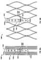
- each support strut array 304may include four support struts 305 connected to the two proximal cells 306 adjacent to an elongated support post 308 and to the two next adjacent proximal cells.
- Proximal cells 306each have a distal end 306a, a proximal end 306b and a middle portion 306c between the distal end 306a and the proximal end 306b.
- Stent 300may include a first row 324 of proximal cells 306 and a second row 328 of proximal cells 306.
- First row 324 and second row 326 of proximal cells 306are oriented substantially parallel to each other.
- First row 324is located distally relative to second row 328. All of the proximal cells 306 collectively define a first end 338 closer to the support strut arrays 304 and a second end 340 farther from support strut arrays 304.
- Post connections 310may be positioned at two locations along each elongated support post 308. As noted above, such positioning reduces post flexibility and the strains experienced in post connections 310. Two post connections 310 may be positioned on opposite sides of the proximal end 308b of an elongated support post 308 and join the elongated support post 308 to the proximal ends 306b of certain proximal cells 306 in the second row 328. Another two post connections 310 may be located on opposite sides at or near the middle 308c of an elongated support post 308 and join the middle of the support post to the middle portions 306c of certain proximal cells 306 in the first row 324.
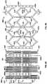
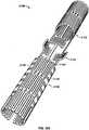
- a stent 400includes a plurality of cells 402, a plurality of support struts 404, one or more elongated support posts 408 and post connections 410 coupling the elongated posts 408 to cells 402.
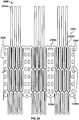
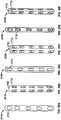
- Figure 5Ashows stent 400 in a flat, rolled out, unexpanded condition
- Figure 5Bdepicts stent 400 in a flat, rolled out, fully-expanded condition.
- Post connections 410are positioned at three locations along each elongated support post 408.
- Stent 400further includes at least one runner or bar 450 extending longitudinally along cells 402. Bars 450 enable the length of stent 400 to change substantially uniformly between the unexpanded and expanded conditions. The height and width of bars 450 may vary to accommodate various strength needs.
- stent 400may further include one or more bars 450 for facilitating uniform expansion of the stent.
- Bars 450join cells 402 from first row 424 through the third row 429. As seen in Figure 5B , each bar 450 passes through cell connections 430 but does not extend past the first end 438 or the second end 440 collectively defined by cells 402. Bars 450 pass through the valleys formed between cells 402.
- Elongated support posts 508are interposed between sets of cells 502 and traverse both rows of cells.
- Each support post 508has a distal end 508a, a proximal end 508b, a middle 508c, and a plurality of eyelets or apertures 532 for suturing stent 500 to the valve leaflets.
- the proximal end 508b of each elongated post 508does not extend beyond the second end 540 collectively defined by all cells 402.
- the distal end 508aextends slightly beyond the first end 538 collectively defined by all cells 502.
- Stent 600may further include an interlocking feature 680 protruding proximally from the proximal end 608b of elongated support post 608.
- Interlocking feature 680may have a substantially triangular shape and is configured to be attached to a delivery instrument or another cell.
- interlocking feature 680has a circular portion 682 having an aperture 684.
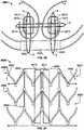
- Proximal cells 706may be arranged in one or more longitudinal rows.
- stent 700may include a first row 724 and a second row 726 oriented substantially parallel to each other.
- Each proximal cell 706may feature an arrow shape in the expanded condition defined by a distal end or peak 706a between two valleys 706b and 706c in one stent section, another peak 706a between two valleys 706b and 706c in another stent section, and a pair of bars 750 connecting the stent sections together.
- Cell connections 730couple adjacent proximal cells 706 arranged in the same row. Each cell connection 730 may be located at a valley 706b, 706c shared by two adjacent proximal cells 706 in the same row.
- Each elongated support post 708 of stent 700has a distal end 708a, a proximal end 708b, and a middle 708c.
- Proximal cells 706may be connected to an elongated support post 708 at three locations via connecting members 710.
- a first pair of connecting members 710may couple opposite sides of the distal end 708a of an elongated support post 708 to two cell connections 730 attached to support struts 704.
- a second pair of connecting members 710may couple opposite sides of the middle 708c of the elongated support post 708 to two cell connections 730 located at the proximal ends 706b, 706c of two different proximal cells 706.
- a third pair of connecting members 710may couple opposite sides near the proximal end 708b of the elongated support post 708 to two cell connections 730 located at the proximal ends 706b, 706c of two other proximal cells 706 located in the second row 726.
- Each distal cell 802has a distal end 802a and a proximal end 802b. All distal cells 802 are arranged in one or more longitudinal rows 814. Cell connections 818 join adjacent distal cells 802 in the same row 814. In the embodiment shown in Figures 9A and 9B , stent 800 includes only one row 814.
- each support strut 807may be connected to a single distal cell 802.
- the proximal end 807b of each support strut 807may be coupled to a proximal cell 806.
- support struts 807may be connected only to the proximal cells 806 adjacent to an elongated support post 808.
- Each proximal cell 806may have an inverted arrow shape upon expansion defined by a pair of peaks 806a on opposite sides of a valley 806b in one stent section, another pair of peaks 806a on opposite sides of a valley 806b in another stent section, and a pair of bars 850 connecting the stent sections together.
- Proximal cells 806may be arranged in one or more longitudinal rows.
- stent 800includes proximal cells 806 in a first row 824 and in a second row 826.
- Cell connections 830interconnect adjacent proximal cells 806 positioned in the same row. Each cell connection 830 may be located at a peak 806a shared by two adjacent proximal cells 806 located in the same row.
- the valleys 806b at the proximal ends of the cells in the second row 824may also form the valleys 806b at the distal ends of the adjacent cells in the first row 826.
- Stent 800may further include an interlocking feature 880 protruding proximally from the proximal end 808b of each elongated support post 808.
- Interlocking feature 880may be substantially similar to the interlocking feature 780 of stent 700.
- the stent 800 of a new valvemay be fitted over an existing surgical or collapsible bioprosthetic valve V to lock the new valve in place or may be used to lock the stent 800 at the sinotubular junction 4.
- Proximal cells 902are arranged in one or more longitudinal rows.
- Stent 900may include one longitudinal row 914 of proximal cells 902.
- Each distal cell 902has a distal end 902a, a proximal end 902b, and a middle portion 902c between the distal end and the proximal end.
- Cell connections 918join adjacent distal cells 902 at their middle portions 902c.
- the distal end 903a of compartment 903may include an interlocking feature 980 configured to be attached to a delivery system and/or another valve.
- Interlocking feature 980protrudes proximally from the distal end 903a into the interior of compartment 903.
- interlocking feature 980includes rounded protrusion 982 having an aperture 984.
- stent 900includes support struts 904 and support struts 905. At least some of support struts 904 and support struts 905 may be made partially or entirely of a substantially rigid material to minimize a change in stent length, thereby reducing the risk of valve damage during crimping of the prosthetic valve and providing a more consistent valve function in various implant diameters.
- Support struts 904interconnect the proximal end 902b of a distal cell 902 to the distal end 906a of a proximal cell 906. In some embodiments, every distal cell 902 may be connected to a proximal cell 906 via a support strut 904.
- the distal ends 905a of the two support struts 905may converge for attachment to the proximal end 903b of compartment 903 at a single point.
- support struts 905define an oblique angle relative to one another.
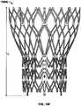
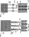
- FIG. 10Billustrates a stent 1000A
- Figure 10Cillustrates a stent 1000B which are substantially similar to one another.
- Stents 1000A and 1000Bhave interlocking features 1080 at different locations and different kinds of elongated support posts.
- Stent 1000Afurther includes one or more cell spacers 1070 each interconnecting two adjacent distal cells 1002 of the first row 1014.
- stent 1000Aincludes a cell spacer 1070 for each elongated support post 1008.
- a cell spacer 1070may form a distal portion or end of a distal cell 1002 which is located in the second row 1016 and connected to an elongated support post 1008.
- Cell spacer 1070permits further expansion of stent 1000A, and may provide clearance between distal cells 1002 to accommodate the coronary arteries.
- the distal cells 1002 in third row 1022are directly connected to the proximal cells 1006 in a first row 1024 by a runner or bar 1050.
- Bar 1050is connected at one end to a cell connection 1018 in the third row 1022 of distal cells 1002, and at the other end to cell connection 1030 in the first row 1024 of proximal cells 1006.
- Stent 1500may alternatively incorporate a full-length or elongated support post 1509 as shown in Figure 12B .
- Elongated support post 1509is longer and narrower than shortened support post 1508 and includes reduced width portion 1509d.
- Reduced width portion 1509dis located near the proximal end 1509b of the elongated support post 1509 and allows stent 1500 to be more compactly crimped.
- the overall reduced width of elongated support post 1509also allows a user to secure the knots connecting a valve to elongated support post 1509 away from the cells.
- elongated support post 1509includes eyelets or apertures 1532 and a base portion 1509e.
- the support strut location and typeis another primary design parameter that can change the amount of flexibility of the support post. As the support strut is connected farther from the support post, it allows the load from the commissural region during back-pressure to be distributed along the stent body gradually, instead of abruptly at the commissures and struts connected to the stent. This not only decreases the dynamic loading on the valve leaflets, but also reduces strain on the stent. The highest dynamic loads are experienced in the embodiments in which the support struts are connected directly to the support posts ( e . g ., Figures 11A-11D ).
- Each support strut 2104has a distal end 2104a, a proximal end 2104b and a middle portion 2104c between the distal end and the proximal end.
- the distal end 2104a of each support strut 2104is connected to a distal cell 2102.
- the proximal end 2104b of each support strut 2104is connected to a proximal cell 2106.
- each support strut 2104is connected to a proximal cell 2106f located midway between two elongated support posts 2108 in order to increase flexibility and minimize the dynamic loads exerted on the elongated support posts.
- FIG. 20Aillustrates the ability of stent 2100 to conform to an aortic arch bend with little effect on its valve-functioning part ( i.e ., proximal cells 2106).
- Figure 20Bshows stent 2100 with the valve section ( i.e ., proximal cells 2106) functioning relatively free of adverse contortion from shortening and lengthening motions of the relative anatomical structures.
- Figure 21Ashows a support strut 2204A with a tapered proximal portion 2204t.
- Figure 21Billustrates a support strut 2204B featuring a uniform diameter or cross-section along its entire length.
- Figure 21Cdepicts a support strut 2204C with a tapered middle portion 2204k.
- the support struts shown in Figures 21A, 21B, and 21Ccan bend and twist but cannot elongate.
- Figure 21Gshows a support strut 2204G with nested longitudinal cells 2204v in its middle portion and extending toward the proximal end of the support strut.
- Support strut 2204Gcan bend more easily than previous embodiments, but may have limited elongation capabilities.
- Figure 21Hshows a support strut 2204H with a nested coil of cells 2204x in its middle portion. The nested coil of cells 2204x can bend, twist and elongate via a circular nested mechanism.
- Figure 21Iillustrates a support strut 2204I with a single serpentine or sinusoidal link 2204y in its middle. portion.
- Support strut 2204Ican bend and twist and can also elongate more easily than previous embodiments.
- Figure 21Jshows a pair of support struts 2204J each having serpentine-shaped links 2204z in their middle portions.
- the serpentine-shaped link 2204z of one support strut 2204Jis offset to the left (or away from the other support strut 2204J), while the serpentine-shaped link 2204z of the other support strut 2204J is offset to the right (or away from the other support strut 2204J).
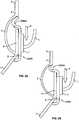
- each support strut 2304can be independently contoured to the anatomy, the distal end 2304a of each support strut 2304 can anchor in the aorta, above and/or below the sinotubular junction, around the free edge of the valve leaflets.
- Stent 2300does not have distal cells. The absence of distal cells provides stent 2300 with greater post flexibility while still providing additional anchoring capabilities.
- Figure 22shows support struts 2304 with a substantially straight configuration, this preferably is prior to final processing to provide the support struts with desired configurations.
- each support strut 2304has a curved profile 2304c near its distal end 2304a.
- the curved profiles 2304cinitially bend outwardly or away from one another to anchor just distally of the sinotubular junction, but, closer to the distal ends 2304a, the curved profiles 2304c bend inwardly or toward one another to reduce the possibility of aortic perforation or dissection by a support strut 2304.
- the stentincludes support struts 2304 designed to seat around and/or just proximal to the sinotubular junction in the distal portion of the sinus.
- the support struts 2304 of the embodiment shown in Figure 23Balso have a curved profile 2304d near their distal ends 2304a. This curved profile 2304d initially bends outwardly (or away from one another) and then proximally, thereby forming a hook, but, closer to the distal ends 2304a, the curved profile 2304d bends distally.
- a single stent 2300may have the support struts shown in both Figures 23A and 23B . Additionally, support struts 2304 may be used to latch onto features of previously implanted prosthetic valves, such as the spacer 770 shown in Figures 8A and 8B .
- Figure 26is a top view of a stent 2500 having a support post 2508 and secondary posts 2510 used for reinforcement.
- Secondary posts 2510may be made from a material, such as stainless steel, which is more resistant to fatigue than Nitinol, from which stent 2500 may be made.
- Support post 2508has at least two eyelets or apertures 2532.
- Each secondary post 2512has two eyelets 2512 oriented substantially perpendicular to each other in a crossing pattern.
- Secondary posts 2510may be attached to support post 2508 using sutures S.
- One suture Spasses through one eyelet 2532 of support post 2508 and through a corresponding eyelet 2512 of one secondary post 2510, thereby attaching that secondary post to the support post.
- Another suture Spasses through another eyelet 2532 of support post 2508 and through a corresponding eyelet 2512 of the other secondary post 2510, thereby attaching that secondary post to the support post.
- both secondary posts 2510are attached to support post 2508 with sutures S.
- the secondary posts 2510may also be attached to each other by passing a suture S through an eyelet 2512 of one secondary post 2510 and another eyelet 2512 of the other secondary post 2510.
- the secondary posts 2510sandwich the tissue of the two leaflets K.
- Leaflets Kmay be tissue, but this design lends itself to polymer dip coating onto secondary posts 2510 before attaching the resulting subassembly onto strut 2500 via large eyelets at the top and bottom of the support posts.
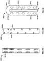
- FIG. 27shows one-third of the side of a stent 2600 that does not have support posts.
- Stent 2600includes at least two rows of cells 2606, and may include a first row 2622 and a second row 2624 of cells 2606.
- Cell connections 2630interconnect adjacent cells 2606 in the same row.
- Bars 2650couple cells 2606 positioned in adjacent rows and may be formed of a substantially rigid material.
- a fabric or tissue cuff 2690may be attached around the interior or exterior of stent 2600 and cover almost the entirety of the cells 2606, leaving only open areas 2692 for the coronary arteries. Open areas 2692 expose only distal portions 2606a of some cells 2606.
- Secondary posts 2610may be sutured to the cuff 2690, to bars 2650 and/or to the segments forming cells 2606.
- Figures 28A-28Fillustrate different reinforcements or secondary posts 2710, 2720, and 2730, which may be attached as rigid structures to any suitable stent as shown in Figure 26 .
- All secondary posts 2710, 2720, 2730may have eyelets 2732 along their length for receiving sutures. Eyelets 2732 may also be positioned on multiple sides of each secondary post 2710, 2720, 2730 to allow for multidirectional suturing.
- the eyelet 2732 closest to the distal end 2702 of the secondary post 2710, 2720, or 2730may not be spaced apart from the adjacent eyelet 2732 as much as the other eyelets 2732 are spaced apart from each other.
- the edges of the eyelets 2732 and the edges of the secondary posts 2710, 2720 and 2730are preferably rounded to eliminate suture and leaflet abrasion.
- Figures 29A and 29Bshow reinforcements or secondary posts 2810 and 2820 adapted to be attached to a stent as shown in Figure 26 .
- Posts 2810 and 2820have a hollow core and may feature a smoothly curved or cylindrical shape.
- Post 2810has eyelets 2812 along its length. Eyelets 2812 may have an oblong or elliptical shape.
- Post 2820may have two different kinds of eyelets 2822 and 2824. Eyelets 2822 are in the form of alternating through-holes with a substantially oblong or elliptical shape.
- a partial eyelet 2824 located near the distal end 2820a of post 2820has a substantially circular shape to hold a suture.
- Figure 30shows a reinforcement 2900 that may be attached to the stent, as shown in Figure 26 , in lieu of the secondary posts.
- Reinforcement 2900includes a first column 2910, a second column 2912, and an arch 2914 interconnecting the first and second columns.
- First column 2910has a first end 2910a and a second end 2910b.
- Second column 2912has a first end 2912a and a second end 2912b.
- Arch 2914connects the first end 2910a of the first column 2910 to the first end 2912a of the second column 2912 and sets the width W between the first and second columns.
- the first column 2910 and the second column 2912define a gap 2916 between them.
- Gap 2916has a width W and is dimensioned to receive the valve leaflets K ( Fig. 26 ). With leaflets K sandwiched between the first column 2910 and the second column 2912, arch 2914 absorbs the opening load of the leaflets instead of the sutures since columns 2910 and 2912 may want to pull apart.
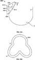
- Figure 31Ashows a pliable reinforcement 3000 folded over a free edge of a leaflet and sutured to itself and to the stent frame or post.
- reinforcement 3000may be attached to a free edge of a leaflet at the commissure 9, but away from the belly region 8 of the valve leaflet, as shown in Figure 31A .
- reinforcement 3000may be attached to the entire sutured edge of the leaflet, which would result in the shape seen in Figure 31B .
- Reinforcement 3000includes a securing section 3004 and an optional flap 3002 for additional suturing and securement to a support post.
- reinforcement 3000is folded onto itself along a folding line F L .
- a folding area 3008is folded over a securing section 3004 as indicated by arrow M to form a substantially V-shaped structure.
- reinforcement 3000partially wraps a free edge of a valve leaflet.
- Suturesmay be used to secure reinforcement 3000 in a folded condition.
- One or more suturesmay pass over the free edge of the leaflet outside of reinforcement 3000 to secure the reinforcement 3000 in a folded condition. In such case, the suture should be more than 1mm from the free edge of the leaflet.
- Folding area 3008defines cutout 3010 which may be substantially V-shaped for straddling the leaflets.
- Securing section 3004has a base 3006 aligned with an eyelet at the proximal end of a support post, and an angled side 3014 oriented at an oblique angle relative to folding line F L and base 3006. Angled side 3014 of securing section 3004 biases the valve opening away from a support post. For instance, angled side 3014 may bias the valve opening about 3mm away from a support post.
- reinforcement 3000may optionally include a flap 3002 which provides additional securement to the support post.
- additional suturesmay attach the flap 3002 to the support post.
- Flap 3002may also protect moving leaflets from knots securing the reinforcement 3000 to the support post.
- the distance between the edge of flap 3002 and angled side 3014 along folding line F Lshould be sufficient to keep the leaflets from opening against the stent.
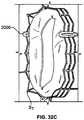
- Reinforcement 3000may be attached to a stent S T as shown in Figure 33A. Regardless of the manner in which stent S T is deformed, as shown in Figures 33B and 33C, there is a low likelihood of the valve leaflet abrading against the stent.
Landscapes
- Health & Medical Sciences (AREA)
- Engineering & Computer Science (AREA)
- Biomedical Technology (AREA)
- Cardiology (AREA)
- Oral & Maxillofacial Surgery (AREA)
- Transplantation (AREA)
- Heart & Thoracic Surgery (AREA)
- Vascular Medicine (AREA)
- Life Sciences & Earth Sciences (AREA)
- Animal Behavior & Ethology (AREA)
- General Health & Medical Sciences (AREA)
- Public Health (AREA)
- Veterinary Medicine (AREA)
- Physics & Mathematics (AREA)
- Optics & Photonics (AREA)
- Prostheses (AREA)
Description
- The present disclosure relates to prosthetic heart valves and, more specifically, to prosthetic heart valves having a collapsible stent frame.
- Current collapsible prosthetic heart valve designs are for use within high-risk patients who may need a cardiac valve replacement, but who are not appropriate candidates for conventional open-chest, open-heart surgery. To address this problem, collapsible and re-expandable prosthetic heart valves have been developed that can be implanted transapically or percutaneously through the arterial system. However, such collapsible valves may have important clinical issues because of the nature of the patient's native stenotic leaflets that may not be resected as with the standard surgical practice of today. Additionally, patients with uneven calcification, bicuspid disease, and/or aortic insufficiency may not be treated well with the current collapsible prosthetic valve designs. The limitation of relying on evenly calcified leaflets has several issues, such as: (1) perivalvular leakage (PV leak), (2) valve migration, (3) mitral valve impingement, (4) conduction system disruption, etc., all of which can have adverse clinical outcomes. To reduce these adverse events, the optimal valve would seal and anchor to the cardiac tissue adequately without the need for excessive radial force that could harm nearby anatomy and physiology. An optimal solution may be to employ a stent that exerts a radial outward force just large enough to hold open the native stenotic/insufficient leaflets, and to use additional anchoring features more reliant on another anchoring methodology while reducing leaflet/stent stresses.
- After multiple clinical valve failures during the late 1960's and early 1970's, a series of investigations on leaflet failure (e.g., dehiscence at the commissures) and stent post flexibility began and continue to be explored today. (Reis, R.L., et al., "The Flexible Stent: A New Concept in the Fabrication of Tissue Heart Valve Prostheses", The Journal of Thoracic and Cardiovascular Surgery, 683-689, 1971.) In-vitro, animal, and clinical investigations showed that "a flexible stent greatly reduces stress on the valve," which was as large as a 90% reduction of the closing stresses near the commissures when flexibility and coaptation area were maximized.
- In more recent years, several groups have shown (e.g., via numerical computations) the importance of stent post flexibility during opening and closing phases to reduce leaflet stress and therefore tissue failure. (Christie, G.W., et al., "On Stress Reduction in Bioprosthetic Valve Leaflets by the Use of a Flexible Stent," Journal of Cardiac Surgery, Vol. 6, No. 4, 476-481, 1991;Krucinski, S., et al., "Numerical Simulation of Leaflet Flexure in Bioprosthetic Valves Mounted on Rigid and Expansile Stents," Journal of Biomechanics, Vol. 26, No. 8, 929-943, 1993.) In response to several rigid Ionescu-Shiley clinical valve failures in which the leaflets tore free at the commissures, Christie et al. (cited above) explored what would happen if a similar design was made with optimal flexibility. Stresses at the post tops were shown to be five times greater than at the belly of a leaflet. Thus, to optimize the design, the stent was made more flexible until the stresses in the leaflets were comparable to those in the leaflet belly. It was shown that a 0.2-0.3mm deflection was all that was needed to make a significant reduction in stress, but that a deflection of approximately 1.1mm would reduce the stress by up to 80%. Furthermore, it was explained that deflection beyond 1.1mm was not only difficult to achieve with the available material and design, but did not result in additional stress reduction.
- Krucinski et al. (also cited above) have shown that a 10% expansion (as may be the case during the opening phase of a Nitinol stent) may reduce sharp flexural stresses by up to 40% (e.g., "hooking"). This is likely due to the stent functioning in harmony with the patient's aortic root, or in other words, the commissures of the native valve moving outward during systole.
EP 1 690 515 A1 describes a cardiac-valve prosthesis, which can be used, for example, as valve for percutaneous implantation, comprises an armature for anchorage of the valve prosthesis in the implantation site. The armature defines a lumen for passage of the blood flow and supports a set of prosthetic valve leaflets. The armature comprises two annular parts connected by anchorage formations, which extend as connection of the annular parts, with the capacity of projecting radially with respect to the prosthesis; and supporting formations for the set of leaflets, said formations being carried by at least one of the annular parts so as to leave substantially disengaged the aforesaid lumen for passage of the blood.- Although the above analyses and data may not be directly applicable to the collapsible valve designs detailed later in this specification, the basic understanding and theory about how pericardial tissue leaflets interact with a stent design as it functions are important to incorporate into any design where durability is paramount. It is possible that with good engineering design of the post and leaflet attachment, commissural dehiscence will not be a primary failure mechanism.
- The present disclosure relates to prosthetic heart valves. In one embodiment, a prosthetic heart valve includes a stent having a proximal end, a distal end, an expanded condition and a collapsed condition. The stent includes a plurality of distal cells at the distal end, a plurality of proximal cells at the proximal end, a plurality of support struts coupling the proximal cells to the distal cells, and at least one support post connected to a multiplicity of the proximal cells. The proximal cells are longitudinally spaced apart from the distal cells. A valve structure is connected to the at least one support post.
- In another embodiment, a prosthetic heart valve includes a stent having a proximal end, a distal end, an expanded condition and a collapsed condition. The stent includes a plurality of distal cells at the distal end, a plurality of proximal cells at the proximal end, and at least one support post connected to a multiplicity of proximal cells. At least a portion of the proximal cells are directly connected to the distal cells. A valve structure is connected to the at least one support post.
- In a further embodiment, a prosthetic heart valve includes a stent having a proximal end, a distal end, an expanded condition and a collapsed condition. The stent includes a plurality of cells at the proximal end, a plurality of support struts at the distal end, and at least one support post connected to a multiplicity of the cells. Each support strut has a first end connected to one of the cells and a free end. A valve structure is connected to the at least one support post.
- In yet another embodiment, a prosthetic heart valve includes a stent having a proximal end, a distal end, an expanded condition and a collapsed condition. The stent includes a plurality of cells, at least one support post connected to a multiplicity of the cells, and a reinforcement secured to the at least one support post. A valve structure is connected to the at least one support post, the reinforcement being adapted to secure leaflets of the valve.
- Various embodiments will now be discussed with reference to the appended drawings. It is appreciated that these drawings depict only some embodiments of the invention and are therefore not to be considered limiting of its scope.
FIG. 1 is a schematic longitudinal cross-section of an aortic root;FIG. 2 is a developed view of a stent with a plurality of posts each connected to cells at two locations;FIG. 3 is a developed view of a stent with a plurality of posts each connected to cells only at their proximal ends;FIG. 4 is a developed view of a stent with a plurality of posts each connected to cells at their proximal ends and middle portions;FIG. 5A is a developed view of a stent in an unexpanded condition with a plurality of posts each connected to cells at three locations;FIG. 5B is a developed view of the stent ofFIG. 5A in an expanded condition;FIG. 6A is a developed view of a stent in an unexpanded condition with a plurality of posts each connected to cells at three locations;FIG. 6B is a developed view of the stent ofFIG. 6A in an expanded condition;FIG. 7A is a partial perspective view of a stent showing a post connected to cells at two locations;FIG. 7B is a partial front elevational view of a stent showing a post connected to cells at three locations;FIG. 8A is a developed view of a stent in an unexpanded condition and including a plurality of posts and a plurality of spacers interconnecting certain cells;FIG. 8B is a front elevational view of the stent ofFIG. 8A in an expanded condition;FIG. 9A is a developed view of a stent in an unexpanded condition including support struts each having a curved middle portion;FIG. 9B is a front elevational view of the stent ofFIG. 9A in an expanded condition;FIG. 10A is a partial developed view of a stent in an unexpanded condition and including a plurality of substantially rigid posts and an interlocking feature;FIG. 10B is a partial front elevational view of a stent in an expanded condition and including a plurality of substantially rigid posts and an interlocking feature;FIG. 10C is a partial front elevational view of a stent in an expanded condition and including a plurality of substantially rigid posts and an interlocking feature;FIG. 10D is front elevational view of a stent flared to anchor at a sinotubular junction;FIG. 10E is a front elevational view of a stent flared to anchor just above the sinotubular junction and at the base of the aorta;FIG. 10F is a front elevational view of a stent flared to anchor within the ascending aorta;FIG. 11A is a developed view of a stent in an unexpanded condition and including a plurality of posts each connected at one end only to support struts;FIG. 11B is a developed view of a stent in an unexpanded condition and including a plurality of posts and a plurality of support strut sets, each set being connected directly to a post and to cells adjacent the post;FIG. 11C is a developed view of a stent in an unexpanded condition and including a plurality of posts and a plurality of support strut sets, each support strut set being directly connected to a single post;FIG. 11D is a developed view of a stent in an unexpanded condition and including a plurality of posts and a plurality of support struts, each support strut being connected directly to a distal end of a single post;FIG. 12A is a partial developed view of a stent in an unexpanded condition and including at least one shortened post;FIG. 12B is an enlarged view of an alternate post for incorporation into the stent ofFIG. 12A ;FIG. 12C is an enlarged view of an alternate post for incorporation into the stent ofFIG. 12A ;FIG. 13A is a partial developed view of a stent in an unexpanded condition and including a post with a slidable portion;FIG. 13B is a partial developed view of the stent ofFIG. 13A in an expanded condition;FIG. 14A is a partial developed view of a stent in an unexpanded condition with an elongated support post having a diamond-shaped collapsible post structure;FIG. 14B is a partial developed view of the stent ofFIG. 14A in an expanded condition;FIG. 15A is a partial developed view of a stent in an unexpanded condition with an elongated support post having a collapsible post feature;FIG. 15B is a partial developed view of the stent ofFIG. 15A in an expanded condition;FIG. 16A is a partial developed view of a stent in an unexpanded condition with an elongated support post having an hourglass-shaped collapsible post feature;FIG. 16B is a partial developed view of the stent ofFIG. 16A in an expanded condition;FIG. 17A is a developed view of a stent in an unexpanded condition with support struts connected to a proximal cell spaced from the elongated support post;FIG. 17B is a developed view of a proximal portion of the stent ofFIG. 17A ;FIG. 18A is a developed view of a stent with a support strut connected to a proximal cell located halfway between two elongated support posts;FIG. 18B is a perspective view of the stent ofFIG. 18A in an expanded condition;FIG. 18C is a perspective view of the stent ofFIG. 18A in an unexpanded condition;FIG. 19 is a perspective view of the stent ofFIG. 18A in an expanded condition and subjected to a torsional force;FIG. 20A is a perspective view of the stent ofFIG. 18A in an expanded condition and being twisted;FIG. 20B is a perspective view of the stent ofFIG. 18A in an expanded condition and under longitudinal compression;FIG. 21A is a side elevational view of a support strut with a tapered proximal end;FIG. 21B is a side elevational view of a support strut with a uniform width;FIG. 21C is a side elevational view of a support strut with a tapered middle portion;FIG. 21D is a side elevational view of a support strut with an inverted C-shaped middle portion;FIG. 21E is a side elevational view of a support strut with a C-shaped middle portion;FIG. 21F is a side elevational view of a support strut with a rectangular middle portion;FIG. 21G is a side elevational view of a support strut with nested longitudinal cells;FIG. 21H is a side elevational view of a support strut with a nested coil of cells;FIG. 21I is a side elevational view of a support strut with a sinusoidal-shaped middle portion;FIG. 21J is a side elevational view of a pair of support struts with offset sinusoidal-shaped middle portions;FIG. 22 is a developed view of a stent with support struts cantilevered from proximal cells;FIG. 23A is a partial perspective view of an embodiment of the stent ofFIG. 22 in an expanded condition with support struts having C-shaped distal portions;FIG. 23B is a partial perspective view of an embodiment of the stent ofFIG. 22 in an expanded condition with support struts having hook-shaped distal portions;FIG. 24 is a highly schematic, partial longitudinal cross-section showing the stent ofFIG. 23A positioned in an aortic annulus;FIG. 25 is a highly schematic, partial longitudinal cross-section showing the stent ofFIG. 23B positioned in an aortic annulus;FIG. 26 is a top partial view of a stent reinforced with two secondary posts;FIG. 27 is a partial developed view of a portion of a stent with a cuff and reinforced with two secondary posts;FIG. 28A is a side elevational view of a secondary post with a substantially circular cross-section;FIG. 28B is a perspective view of the secondary post ofFIG. 28A ;FIG. 28C is a side elevational view of a secondary post with a substantially rectangular cross-section;FIG. 28D is a perspective view of the secondary post ofFIG. 28C ;FIG. 28E is a side elevational view of a secondary post with a substantially triangular cross-section;FIG. 28F is a perspective view of the secondary post ofFIG. 28E ;FIG. 29A is a side elevational view of a secondary post with a hollow core;FIG. 29B is a side elevational view of a secondary post with a hollow core and two different kinds of eyelets;FIG. 30 is a side elevational view of a reinforcement for a stent including two columns connected by an arch;FIG. 31A is a highly schematic, partial longitudinal cross-section showing a reinforcement for use with a stent and adapted to be folded onto itself;FIG. 31B is a highly schematic top view of the reinforcement ofFIG. 31A outlining the entire free end of a leaflet;FIG. 32A is a perspective view of a prosthetic valve incorporating the reinforcement ofFIG. 31A ;FIG. 32B is a perspective view of a prosthetic valve incorporating the reinforcement ofFIG. 31A while the valve is subject to compression; andFIG. 32C is a perspective view of a prosthetic valve incorporating the reinforcement ofFIG. 31A while the valve is subject to compression.- As used herein, the term "proximal" refers to the end of a stent closest to the heart when placing the stent in a patient, whereas the term "distal" refers to the end of the stent farthest from the heart when placing the stent in a patient.
Figure 1 illustrates the anatomy of anaortic root 10 to aid in the understanding of how the stent/valve interacts with the aortic root. (FIG. 1 is fromReul, H., et al., "The geometry of the aortic root in health, at valve disease and after valve replacement," Journal of Biomechanics, Vol. 23, No. 2, 181-91, 1990). The aortic root is the part of the aorta attached to the heart. The aorta is the largest artery in the body, which extends from the left ventricle of the heart down to the abdomen, where it branches off into two smaller arteries. The aorta supplies oxygenated blood to all parts of the body. The aortic root contains the aortic valve and gives rise to the coronary arteries, which are the arteries that supply blood to the heart muscle. As shown inFigure 1 , theaortic root 10 has several features, namely: a left ventricular outflow tract (LVOT) 1; anannulus 2; asinus 3; sinotubular junction (STJ) 4; and an ascendingaorta 5.Figure 1 further depicts several geometrical parameters ofaortic root 10, to wit: DO = orifice diameter; DA = aortic diameter distal to thesinus 3; DB = maximum projected sinus diameter; LA = length of thesinus 3; and LB = distance between DO and DB.- In all the embodiments disclosed herein, the stents are part of a prosthetic heart valve. The stents have an expanded condition and a collapsed condition. In the expanded condition, at least a portion of the stent may have a substantially cylindrical shape.
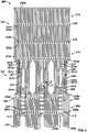
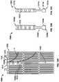
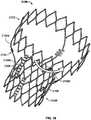
Figure 2 depicts a developed view ofstent 100 in an unexpanded condition, i.e., in a flat, rolled out condition as seen when laser cut from a tube.Stent 100 generally includes one or more rows ofdistal cells 102, at least onesupport strut 104, one or more rows ofproximal cells 106, at least oneelongated support post 108, and at least onepost connection 110 coupling asupport post 108 to at least some of theproximal cells 106. One or more support struts 104 connectdistal cells 102 toproximal cells 106. In some embodiments, three support struts 104 may interconnectproximal cells 106 anddistal cells 102.Stent 100 may nonetheless include more or fewer support struts 104. Regardless of the specific number of support struts 104, support struts 104 longitudinally separateproximal cells 106 fromdistal cells 102 and, therefore,proximal cells 106 are located proximally relative todistal cells 102. Stent 100 or any other embodiment disclosed herein may be wholly or partly formed of any biocompatible material, such as metals, synthetic polymers, or biopolymers capable of functioning as a stent. Suitable biopolymers include, but are not limited to, collagen, elastin, and mixtures or composites thereof. Suitable metals include, but are not limited to, cobalt, titanium, nickel, chromium, stainless steel, and alloys thereof, including nitinol. Suitable synthetic polymers for use as a stent include, but are not limited to, thermoplastics, such as polyolefins, polyesters, polyamides, polysulfones, acrylics, polyacrylonitriles, and polyaramides. For example,stent 100 may be made of polyetheretherketone (PEEK).Distal cells 102 are adapted to be positioned distally relative tosinus 3 to anchor at or near the ascendingaorta 5 andsinotubular junction 4. In certain embodiments,distal cells 102 may be arranged in longitudinal rows. In the embodiment shown inFigure 2 ,stent 100 includes asingle row 114 ofdistal cells 102. Therow 114 ofdistal cells 102 may be oriented substantially perpendicular to support struts 104. WhileFigure 1 shows asingle row 114 ofdistal cells 102,stent 100 may include multiple rows ofdistal cells 102.- Each
distal cell 102 has adistal end 102a, aproximal end 102b, and a middle portion 102c between thedistal end 102a and theproximal end 102b. Acell connection 118 couples two adjacentdistal cells 102. As seen inFigure 2 , eachcell connection 118 is positioned at a middle portion 102c of adistal cell 102. Aside from the two adjacentdistal cells 102,cell connection 118 is not coupled to any otherdistal cell 102. - All
distal cells 102 collectively have afirst end portion 120 and asecond end portion 122. In the embodiment shown inFigure 2 ,first end portion 120 is aligned with the proximal ends 102b of thedistal cells 102, while thesecond end portion 122 is aligned with the distal ends 102a of thedistal cells 102.Distal cells 102 are connected to supportstruts 104 at thefirst end portion 120. In some embodiments, support struts 104 are coupled to the proximal ends 102b of somedistal cells 102. - Support struts 104 interconnect
distal cells 102 andproximal cells 106. As discussed above,stent 100 may include one or more support struts 104. As depicted inFigure 2 ,stent 100 may include onesupport strut 104 for every fiveproximal cells 106.Stent 100 may also include onesupport strut 104 for every sevendistal cells 102. However, these ratios are not critical, and will depend on the size ofproximal cells 106 anddistal cells 102, the desired stiffness ofstent 100 and other considerations. - Each
support strut 104 has afirst end portion 104a, asecond end portion 104b, and a middle portion 104c located between the first and second end portions. Thefirst end portion 104a of eachsupport strut 104 is connected to theproximal end 102b of adistal cell 102. Thesecond end portion 104b of eachsupport strut 104 is connected to thedistal end 106a of aproximal cell 106. Thus, asingle support strut 104 may couple a singledistal cell 102 to a singleproximal cell 106. - As shown in
Figure 2 , the first andsecond end portions support strut 104 may have straight or linear configurations, while the middle portion 104c may have a non-linear configuration. In the embodiment depicted inFigure 2 , the middle portion 104c of eachsupport strut 104 has a sinusoidal or wave shape, but middle portions 102c of one or more support struts 104 may have other non-linear configurations. First andsecond end portions second end portions Figure 2 . Alternatively,portions portion 104b connected to thedistal end 106a of a next adjacentproximal cell 106 to the left or right of the connection depicted inFigure 2 . - As discussed above, at least one
support strut 104 is connected to oneproximal cell 106. Eachproximal cell 106 has adistal end 106a, aproximal end 106b and amiddle portion 106c between thedistal end 106a and theproximal end 106b. Together,proximal cells 106 are configured to impart radial force against the leaflets of a heart valve.Proximal cells 106 may be arranged in longitudinal rows. For example,stent 100 may include afirst row 124 ofproximal cells 106 positioned distally of asecond row 128 ofproximal cells 106. At least onesupport strut 104 is connected to aproximal cell 106 located in thefirst row 124. - A
cell connection 130 couples two adjacentproximal cells 106 positioned in the same row. Theproximal cells 106 in thefirst row 124 are joined to theproximal cells 106 in thesecond row 128 by sharing one or more common cell legs. - The cells in the
first row 124 and the cells in thesecond row 128 may not form continuous chains of cells. That is, the chain of cells forming thefirst row 124 and the chain of cells forming thesecond row 128 may each be disrupted by one or more elongated support posts 108. Support posts 108 are intended to support the commissures along which the valve leaflets are joined to one another. In this embodiment, as in all of the embodiments described herein, the stent typically has three such support posts 108, one for supporting each of the commissures of the aortic valve. However, where the stent is intended for use in a prosthetic valve other than an aortic valve, the stent may include a greater or lesser number of support posts. Stent 100 may include sets ofproximal cells 106 between elongated support posts 108. For example, as shown inFigure 2 ,stent 100 may include anelongated support post 108 between two sets of fiveproximal cells 106 infirst row 124. However, the number of cells betweensupport posts 108 will depend on the size ofproximal cells 106, the number of cell rows and other such considerations. Support posts 108 may extend longitudinally adjacentfirst cell row 124,second cell row 128 or both cell rows. Similarly, support posts 108 may be connected to proximal cells infirst cell row 124,second cell row 128 or both cell rows.Stent 100 may include onesupport strut 104 for every set ofproximal cells 106 located between two elongated support posts 108. For instance,stent 100 may have onesupport strut 104 for every set of fiveproximal cells 106 located between two elongated support posts 108. In this embodiment, thesecond end portion 104b of eachsupport strut 104 is connected to theproximal cell 106 located midway between two elongated support posts 108.Support strut 104 is not connected to aproximal cell 106 located adjacent to anelongated support post 108.- The support posts 108 may be connected to one or more
proximal cells 106 viapost connections 110. Eachelongated support post 108 has a proximal end 108a, adistal end 108b, and a middle 108c. A plurality of eyelets orapertures 132 are formed in eachsupport post 108 and used for suturing the valve leaflets tostent 100. As seen inFigure 2 ,apertures 132 may have different sizes, shapes and positions. - In the embodiment depicted in
Figure 2 ,post connections 110 are located at or near the middle 108c ofelongated support post 108 to allow for post flexibility during valve cycling, thereby reducing dynamic loading and the resulting in-leaflet stress. Specifically, themiddle portions 106c of twoproximal cells 106 located in thefirst row 124 are attached to opposite sides of the middle portion 108c of eachelongated support post 108. Twoproximal cells 106 arranged in thesecond row 128 are attached near theirmiddle portions 106c to opposite sides of the proximal end 108a of eachelongate support post 108. AlthoughFigure 2 shows postconnections 110 at very specific locations,stent 100 may includepost connections 110 at other locations. - In operation, a user may place a stent 100 (or any other stent disclosed herein) using any conventional methods. For instance, the user may
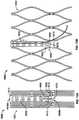
first place stent 100 in a crimped condition and then insert it into a delivery instrument or system. The delivery instrument may be advanced through the patient's vasculature or through a transapical procedure untilstent 100 reaches the desired destination near the aortic valve. Subsequently, the user deploys and expandsstent 100 at the target site. The structure ofstent 100 described above provides veryflexible support posts 108 which reduce the maximum amount of stress at the commissural interfaces on valve cycling. That is, since the distal ends of the support posts 108 are free from connections to theproximal cells 106, these ends can move freely like a cantilever beam. Figure 3 shows another embodiment of astent 200 withpost connections 210 couplingproximal cells 206 to elongated support posts 208 at different locations than forstent 100.Stent 200 is similar tostent 100 and generally includesdistal cells 202,proximal cells 206, and support strut arrays 204 interconnecting thedistal cells 202 and theproximal cells 206. In some embodiments,stent 200 may include a firstlongitudinal row 214 ofdistal cells 202, a secondlongitudinal row 216 ofdistal cells 202, and a singlelongitudinal row 224 ofproximal cells 206.- Each
distal cell 202 has adistal end 202a, aproximal end 202b, and amiddle portion 202c between thedistal end 202a and theproximal end 202b.Cell connections 218 located at themiddle portions 202c of thedistal cells 202 in each row join two adjacent distal cells in that row together. Thedistal cells 202 in thefirst row 214 are joined to thedistal cells 202 in thesecond row 216 by sharing one or more common cell legs. - The proximal ends 202b of every
distal cell 202 located in thesecond row 216 may be connected to a support strut (205 or 207) of the support strut arrays 204. In the embodiment depicted inFigure 3 ,stent 200 includes three support strut arrays 204 each connected to eightdistal cells 202 and sixproximal cells 206. Each support strut array 204 may alternatively be connected to more or fewerdistal cells 202 andproximal cells 206. Regardless, each support strut array 204 includes one or more support struts (205 or 207) coupled to theproximal cells 206 adjacent to anelongated support post 208 to halt any significant distribution of the strains from post deflection to the remaining stent frame. - Each support strut array 204 may include two kinds of support struts, namely support struts 205 and support struts 207. In some embodiments, each support strut array 204 may include four support struts 205 and two support struts 207. Two support struts 207 may be positioned between two sets of two support struts 205. It is envisioned, however, that support strut arrays 204 may each include more or fewer support struts 205 and 207.
- Each
support strut 205 has afirst end portion 205a, asecond end portion 205b, and amiddle portion 205c between the first and second end portions.First end portion 205a may be connected to aproximal end 202b of adistal cell 202 in thesecond row 216.Second end portion 205b may be connected to adistal end 206a of aproximal cell 206.Middle portion 205c has a straight or linear configuration and interconnects first andsecond end portions first end portion 205a of eachsupport strut 205 defines an oblique angle relative tomiddle portion 205c. This oblique angle may vary from onesupport strut 205 to another. Thesecond end portion 205b of eachsupport strut 205 may also define an oblique angle relative tomiddle portion 205c. This oblique angle may also vary from onesupport strut 205 to another. - Support struts 207 each have a
first end portion 207a, asecond end portion 207b, and amiddle portion 207c between the first and second end portions. Eachsupport strut 207 includes abifurcated section 207d extending from themiddle portion 207c to thefirst end portion 207a.Bifurcated section 207d of eachsupport strut 207 includes twobranches Branches angled portion 207g of thebifurcated section 207d in which the branches define an oblique angle with respect to each other and to first andsecond portions branch first portion 207h, asecond portion 207i, and the transition orangled portion 207g positioned between the first and second portions. In thefirst portion 207h of thebifurcated section 207d,branches second portion 207i. - Each
branch proximal end 202b of adistal cell 202 in thesecond row 216.Branches bifurcated section 207d converge into asingle support member 207k at convergingpoint 207m. Eachsingle support member 207k of support struts 207 may be connected to thedistal end 206a of a singleproximal cell 206 adjacent asupport post 208. - As discussed above, each support strut array 204 is connected to the distal ends 206a of a plurality of
proximal cells 206. Specifically, support struts 207 are connected toproximal cells 206 positioned adjacent asupport post 208, while support struts 205 are connected to theproximal cells 206 which are not adjacent asupport post 208. - Each
proximal cell 206 has adistal end 206a,proximal end 206b and amiddle portion 206c between thedistal end 206a and theproximal end 206b. Theproximal cells 206 collectively define afirst end 238 closer to support strut arrays 204 and asecond end 240 farther from support strut arrays 204.Proximal cells 206 are arranged in a single longitudinal row.Cell connections 230 located atmiddle portions 206c join adjacentproximal cells 206 together. - Some of the
proximal cells 206 are connected to anelongated support post 208. As seen inFigure 3 , one or more elongated support posts 208 may extend beyond thefirst end 238 collectively defined by all theproximal cells 206 but may not extend past thesecond end 240.Stent 200 may have, for example, oneelongated post 208 for every sixproximal cells 206. - Each
elongated support post 208 has adistal end 208a, aproximal end 208b and a plurality of eyelets orapertures 232 for suturing the valve leaflets to thestent 200. As shown inFigure 3 ,apertures 232 may extend fromdistal end 208a toproximal end 208b and may have different shapes and sizes. In certain embodiments,apertures 232 may have substantially elliptical shapes. - Elongated support posts 208 are connected to
proximal cells 206 bypost connections 210. In the embodiment shown inFigure 3 ,post connections 210 are located only at or near theproximal end 208b ofelongated support post 208 for allowing the elongated support post to deflect inwardly in the direction indicated by arrow G under diastolic back-pressure. AlthoughFigure 3 shows postconnections 210 at precise positions near proximal ends 208b,post connections 210 may be positioned closer or farther fromproximal ends 208b to allow for more or less post flexibility. Eachelongated support post 208 may be connected toproximal cells 206 through twopost connections 210 located on opposite sides of the elongated support post. Figure 4 shows astent 300 includingdistal cells 302,proximal cells 306,support strut arrays 304, elongated support posts 308 andpost connections 310 at two locations along eachelongated support post 308. The positions ofpost connections 310 reduce post flexibility and the strains experienced inpost connections 310 as compared to thepost connections 210 instent 200.- In the embodiment depicted in
Figure 4 ,stent 300 includes asingle row 314 ofdistal cells 302. Eachdistal cell 302 has adistal end 302a, aproximal end 302b and amiddle portion 302c between theproximal end 302b and thedistal end 302a.Cell connections 318 join adjacentdistal cells 302 at theirmiddle portions 302c. Stent 300 may include onesupport strut array 304 for every eightdistal cells 302. Eachsupport strut array 304 may include four support struts 305 joined to fourdistal cells 302. Eachsupport strut array 304 may nonetheless include more or fewer support struts 305. In either event,support strut arrays 304 interconnectdistal cells 302 andproximal cells 306.- Each
support strut 305 has afirst end portion 305a, asecond end portion 305b, and a middle portion 305c located between the first and second end portions. Thefirst end portion 305a of eachsupport strut 305 is connected to theproximal end 302b of at least onedistal cell 302, whereas thesecond end portion 305b of eachsupport strut 305 is connected to thedistal end 306a of at least oneproximal cell 306. - The middle portion 305c of each
support strut 305 has atransition section 305d connected to thefirst end portion 305a.Transition section 305d is oriented at an oblique angle relative to the middle portion 305c. The middle portions 305c of support struts 305 are oriented substantially parallel to each other except at thetransition sections 305d. Thefirst end portions 305a of support struts 305 are also oriented substantially parallel to each other. - The
second end portion 305b of eachsupport strut 305 is connected to thedistal end 306a of at least oneproximal cell 306. Eachsecond end portion 305b has a substantially curved configuration or profile. In some embodiments, eachsupport strut array 304 may include four support struts 305 connected to the twoproximal cells 306 adjacent to anelongated support post 308 and to the two next adjacent proximal cells. That is, two support struts 305 may be connected to aproximal cell 306 adjacent to one side ofelongated support post 308 and to the next adjacent proximal cell, respectively, while another two support struts 305 may be connected to aproximal cell 306 adjacent to the opposite side of the sameelongated support post 308 and to the next adjacent proximal cell, respectively. Proximal cells 306 each have adistal end 306a, aproximal end 306b and a middle portion 306c between thedistal end 306a and theproximal end 306b.Stent 300 may include afirst row 324 ofproximal cells 306 and asecond row 328 ofproximal cells 306.First row 324 and second row 326 ofproximal cells 306 are oriented substantially parallel to each other.First row 324 is located distally relative tosecond row 328. All of theproximal cells 306 collectively define afirst end 338 closer to thesupport strut arrays 304 and asecond end 340 farther fromsupport strut arrays 304. Thefirst end 338 of all theproximal cells 306 is defined by the distal ends 306a of the proximal cells located infirst row 324, whereas thesecond end 340 is defined by the proximal ends 306b of theproximal cells 306 located in thesecond row 328.- A
cell connection 330 joins the middle portions 306c of adjacentproximal cells 306 in thefirst row 324.Other cell connections 330 join the middle portions 306c of adjacentproximal cells 306 in thesecond row 328. Theproximal cells 306 in thefirst row 324 are joined to the proximal cells in thesecond row 328 by sharing one or more common cell legs. - Elongated support posts 308 are connected to some
proximal cells 306 bypost connections 310. In the embodiment depicted inFigure 4 , eachelongated support post 308 traverses the longitudinal length of theproximal cells 306 in thefirst row 324 and at least a portion of the length of theproximal cells 306 in thesecond row 328. Eachelongated support post 308 has adistal end 308a, aproximal end 308b, and a middle 308c. In addition, eachelongated support post 308 includes a plurality of eyelets orapertures 332 for suturingstent 300 to valve leaflets.Apertures 332 may have different shapes and sizes. At least oneelongated support post 308 may extend slightly beyond thefirst end 338 collectively defined by all theproximal cells 306, as seen inFigure 4 . Post connections 310 may be positioned at two locations along eachelongated support post 308. As noted above, such positioning reduces post flexibility and the strains experienced inpost connections 310. Twopost connections 310 may be positioned on opposite sides of theproximal end 308b of anelongated support post 308 and join theelongated support post 308 to the proximal ends 306b of certainproximal cells 306 in thesecond row 328. Another twopost connections 310 may be located on opposite sides at or near the middle 308c of anelongated support post 308 and join the middle of the support post to the middle portions 306c of certainproximal cells 306 in thefirst row 324.- With reference to
Figures 5A and 5B , astent 400 includes a plurality ofcells 402, a plurality of support struts 404, one or more elongated support posts 408 andpost connections 410 coupling theelongated posts 408 tocells 402.Figure 5A showsstent 400 in a flat, rolled out, unexpanded condition, whereasFigure 5B depictsstent 400 in a flat, rolled out, fully-expanded condition.Post connections 410 are positioned at three locations along eachelongated support post 408.Stent 400 further includes at least one runner or bar 450 extending longitudinally alongcells 402.Bars 450 enable the length ofstent 400 to change substantially uniformly between the unexpanded and expanded conditions. The height and width ofbars 450 may vary to accommodate various strength needs. - As discussed above,
stent 400 includes a plurality ofcells 402.Several cell connections 430join cells 402 to one another.Cells 402 may have adistal end 402a, aproximal end 402b, or both a distal end and a proximal end. All thecells 402 collectively define afirst end 438 and asecond end 440 and may be arranged in one or more longitudinal rows. For instance,stent 400 may include afirst row 424, asecond row 426 and athird row 429 ofcells 402 oriented substantially parallel to one another. Thefirst row 424,second row 426 andthird row 429 ofcells 402 are not continuous and may be disrupted by one or more elongated support posts 408 interposed in the rows. - Each
elongated support post 408 includes adistal end 408a, aproximal end 408b, a middle 408c, and a plurality of eyelets orapertures 432 for suturingstent 400 to the valve leaflets. The height Hp of eachelongated support post 408 defines the distance betweendistal end 408a andproximal end 408b. In the embodiment shown inFigure 5A , all elongated support posts 408 are positioned between thefirst end 438 and thesecond end 440 collectively defined bycells 402. The distal ends 402a of thecells 402 in thefirst row 424 extend distally beyond the distal ends 408a of eachelongated support post 408 in the unexpanded condition. The proximal ends of thecells 402 in thethird row 429 extend proximally beyond the proximal ends 408b of eachelongated support post 408 in the unexpanded condition. As a result,cells 402 inrows stent 400 holds onto the stenotic native valve leaflets when the stent is positioned in thevalve annulus 2. Post connections 410 join elongated support posts 408 tocells 402. As shown inFigure 5B ,stent 400 includespost connections 410 at three locations along eachelongated support post 408.First post connections 410 are located on opposite sides of (or near) theproximal end 408b ofelongated posts 408.Second post connections 410 are also positioned on opposite sides of (or near) the middle 408c of elongated support posts 408.Third post connections 410 are located on opposite sides of elongated support posts 408 neardistal ends 408a. Thepost connections 410 neardistal ends 408a may, for example, be positioned at about three-quarters of height Hp.- As discussed above,
stent 400 may further include one ormore bars 450 for facilitating uniform expansion of the stent.Bars 450 joincells 402 fromfirst row 424 through thethird row 429. As seen inFigure 5B , each bar 450 passes throughcell connections 430 but does not extend past thefirst end 438 or thesecond end 440 collectively defined bycells 402.Bars 450 pass through the valleys formed betweencells 402. Stent 400 also includes one or more support struts 404 connected to a portion of the valleys formed between the distal ends 402a ofcells 402 in thefirst row 424. Alternatively, support struts 404 may be connected directly to the distal ends 402a ofcells 402. In some embodiments, support struts 404 may connectcells 402 to another group of cells (not shown).Figure 6A shows astent 500 in a flat, rolled out, unexpanded state, whileFigure 6B illustratesstent 500 in a flat, rolled out, expanded state.Stent 500 includes a plurality ofcells 502, one or more elongated support posts 508, and one ormore bars 550 for enabling the length ofstent 500 to change substantially uniformly between the unexpanded and expanded states. The structure and operation ofstent 500 are similar to the structure and operation ofstent 400, butstent 500 includespost connections 510 specifically located on opposite sides of the distal ends 508a of eachelongated support post 508, rather than inward of the distal ends as withstent 400.Stent 500 may further include one or more support struts 504 joining the distal ends 502a of somecells 502 to another set of cells (not shown).Cells 502 ofstent 500 are arranged in rows, namelyfirst row 524 andsecond row 528.First row 524 andsecond row 528 ofcells 502 are oriented substantially parallel to each other, as seen inFigure 6A .Several cell connections 530join cells 502 to one another. Eachcell connection 530 usually forms a valley or a peak between twocells 502.Bars 550 interconnectadjacent cells 502 positioned in different rows. In some embodiments, bars 550 may be connected to threecell connections 530.Cells 502 collectively define afirst end 538 and asecond end 540.- Elongated support posts 508 are interposed between sets of
cells 502 and traverse both rows of cells. Eachsupport post 508 has adistal end 508a, aproximal end 508b, a middle 508c, and a plurality of eyelets orapertures 532 for suturingstent 500 to the valve leaflets. Theproximal end 508b of eachelongated post 508 does not extend beyond thesecond end 540 collectively defined by allcells 402. Thedistal end 508a extends slightly beyond thefirst end 538 collectively defined by allcells 502. - As seen in
Figures 6A and 6B ,stent 500 includespost connections 510 joining eachelongated support post 508 toadjacent cells 502 at three particular locations along the length of the support post.First post connections 510 join opposite sides near theproximal end 508b of anelongated support post 508 to theadjacent cells 502 located in thesecond row 528.Second post connections 510 join opposite sides of the middle 508c of eachelongated support post 508 to the segments common to theadjacent cells 502 in thefirst row 524 and thesecond row 528.Third post connections 510 join opposite sides of thedistal end 508a of anelongated support post 508 to theadjacent cells 502 located in thefirst row 524. Theselast post connections 510 may be located at the very end of thesupport post 508. Figures 7A and 7B showsimilar stents post connections 610. With reference toFigure 7A ,stent 600A includesdistal cells 602,proximal cells 606 and support struts 604, 605 interconnecting the distal cells and proximal cells.Distal cells 602 andproximal cells 606 are continuously connected around the entire circumference ofstent 600A, thereby allowing symmetric expansion and increased radial force.Distal cells 602 may be arranged in one or more longitudinal rows. For example,stent 600A may include only onerow 614 ofdistal cells 602. Eachdistal cell 602 has adistal end 602a and aproximal end 602b, and may have a diamond shape upon expansion.Distal cells 602 are connected to one another alongrow 614 viacell connections 618. Eachcell connection 618 is positioned at a valley formed between two adjacentdistal cells 602. The proximal ends 602b ofdistal cells 602 may be coupled in an alternating pattern to two different kinds of support struts 604 and 605.Support strut 605 has adistal end 605a, aproximal end 605b, and amiddle portion 605c between the distal end and the proximal end. Thedistal end 605a of eachsupport strut 605 is connected to theproximal end 602b of adistal cell 602, whereas theproximal end 605b of eachsupport strut 605 is connected to thedistal end 606a of aproximal cell 606.Support strut 604 has adistal end 604a, aproximal end 604b, and a middle portion 604c between the distal end and the proximal end. Thedistal end 604a of eachsupport strut 604 is connected to theproximal end 602b of adistal cell 602. Theproximal end 604b of eachsupport strut 604 is coupled to thedistal end 606a of aproximal cell 606. The middle portion 604c of eachsupport strut 604 includes asection 604d featuring a non-linear shape. For example,non-linear section 604d may have a sinusoidal or wave shape.Proximal cells 606 are arranged in one or more longitudinal rows. For instance,stent 600A may include afirst row 624 and asecond row 626 ofproximal cells 606.First row 624 andsecond row 626 ofproximal cells 606 are oriented substantially parallel to each other.- Each
proximal cell 606 may have an arrow shape in the expanded condition defined by a pair ofpeaks 606a on opposite sides of avalley 606b in one stent section, another pair ofpeaks 606a on opposite sides of avalley 606b in another stent section, and a pair ofbars 650 connecting the stent sections together. Cell connections 630 interconnectproximal cells 606 positioned in the same row. Eachcell connection 630 may be positioned at apeak 606a shared by two adjacentproximal cells 606 located in the same row.Bars 650 not only defineproximal cells 606, but also interconnectproximal cells 606 located in adjacent rows, thereby allowing uniform expansion ofproximal cells 606. Eachbar 650 may be connected to one ormore cell connections 630.Stent 600A further includes one or more elongated support posts 608. Eachelongated support post 608 has adistal end 608a, aproximal end 608b, and a middle 608c, and includes one or more eyelets orapertures 632 for suturingstent 600A to the valve leaflets.- Stent 600 may further include an
interlocking feature 680 protruding proximally from theproximal end 608b ofelongated support post 608.Interlocking feature 680 may have a substantially triangular shape and is configured to be attached to a delivery instrument or another cell. In one embodiment, interlockingfeature 680 has acircular portion 682 having anaperture 684. Post connections 610 join eachelongated support post 608 toproximal cells 606 located adjacent to the support post. In the embodiment shown inFigure 7A ,stent 600A includes twopost connections 610 on opposite sides of the middle 608c of eachelongated support post 608 and another twopost connections 610 on opposite sides near theproximal end 608b of eachelongated support post 608. As a result, the distal ends 608a of elongated support posts 608 are free and disconnected from anyproximal cell 606. This configuration providesstent 600A with a high degree of flexibility and reduces the likelihood of distortion in the distal portion ofelongated support post 608 contorting the commissure region and thus the valve function.- The
proximal cells 606 adjacent to thedistal end 608a ofelongated support post 608 may be joined to each other by a particular kind ofcell connection 631.Cell connection 631 does not form a peak but rather a straight line in the annular direction ofstent 600A. As seen inFigure 7A ,cell connection 631 is not connected toelongated support post 608, thereby enabling thedistal end 608a of the stent post to flex. - Referring to
Figure 7B ,stent 600B is substantially similar tostent 600A. However,stent 600B may includepost connections 610 at three locations alongelongated support post 608. For example,stent 600B may includepost connections 610 on opposite sides of thedistal end 608a of eachelongated support post 608,other post connections 610 on opposite sides of the middle 608c of eachelongated support post 608, andother post connections 610 on opposite sides near theproximal end 608b of eachelongated support post 608. As discussed above,post connections 610 join elongatedsupport post 608 toproximal cells 606 adjacent toelongated support post 608. - In the embodiment shown in
Figure 7B ,stent 600B only includesstruts 605 interconnecting thedistal cells 602 and theproximal cells 606 and does not contain anystruts 604 with anon-linear section 604d. It is envisioned, however, thatstent 600B may include bothstruts 604 and struts 605. Stent 600B may include additional cellstructural members 660 located distally of eachelongated support post 608. Each cellstructural member 660 includes afirst support member 662 and asecond support member 664 joined at a peak ordistal end 666.First support member 662 andsecond support member 664 together form a triangular structure connected toproximal cells 606 located on opposite sides of thedistal end 608a ofelongated support post 608. Eachfirst support member 662 may be connected to adistal end peak 606a of aproximal cell 606 via acell connection 630. Eachsecond support member 664 may be connected to astraight connection 631. In the embodiment shown inFigure 7B ,connection 631 is not connected toproximal cells 606 or to anelongated support post 608, and is only coupled to thesecond support members 664 of each cellstructural member 660. As shown inFigure 7B , theconnection 631 and the connected portions ofsupport members 664 and struts 605 may be fitted over an existing surgical or collapsible bioprosthetic valve V to lock the new valve in place. In lieu ofelongated support post 608,stent 600A orstent 600B may include continuousproximal cells 606 disjointed in the area where the leaflet commissures would be attached.Figure 8A shows astent 700 in a flat, rolled out, unexpanded condition andFigure 8B showsstent 700 in an expanded condition.Stent 700 generally includesdistal cells 702,proximal cells 706, and a plurality of support struts 704 interconnectingdistal cells 702 andproximal cells 706.Distal cells 702 are arranged in one or more longitudinal rows. In the embodiment shown inFigures 8A and 8B ,stent 700 includes onelongitudinal row 714 ofdistal cells 702.Cell connections 718 join adjacentdistal cells 702 arranged in the same row. Some adjacentdistal cells 702, however, are connected byspacers 770.Spacers 770 allow symmetric expansion ofdistal cells 714 and additional spacing for the coronary arteries. Eachspacer 770 may further include an interlocking feature, eyelets, radiopaque material, a landing-zone/latch-site for implanting another similar expandable valve, or a combination thereof.- Although both
spacers 770 andcell connections 718 connect adjacentdistal cells 702,spacers 770 separate adjacentdistal cells 702 farther from each other thancell connections 718. In some embodiments, threecell connections 718 may continuously couple four adjacentdistal cells 702 before aspacer 770 joins the next adjacent distal cell.Spacers 770 may be arranged betweencells 702 so as to be positioned in axial alignment with support posts 708. - Each
distal cell 702 has adistal end 702a and aproximal end 702b. Upon expansion ofstent 700, eachdistal cell 702 may have a diamond shape, as shown inFigure 8B . - The proximal ends 702b of each
distal cell 702 may be connected to asupport strut 704. Eachsupport strut 704 has adistal end 704a andproximal end 704b. Thedistal end 704a of eachsupport strut 704 is coupled to adistal cell 702. Theproximal end 704b of eachsupport strut 704 is connected to aproximal cell 706. Specifically, theproximal end 704b of eachsupport strut 704 is coupled to acell connection 730 located at a valley formed between two adjacentproximal cells 706. - As seen in
Figure 8B , theproximal end 704b of eachsupport strut 704 is positioned proximally of the distal ends 708a of elongated support posts 708. As a consequence, the outward flaring ofstent 700 in an expanded condition can start proximally to the distal end of the cylindrical region (i.e., proximal cells 706). Proximal cells 706 may be arranged in one or more longitudinal rows. In some embodiments,stent 700 may include afirst row 724 and asecond row 726 oriented substantially parallel to each other. Eachproximal cell 706 may feature an arrow shape in the expanded condition defined by a distal end orpeak 706a between twovalleys 706b and 706c in one stent section, anotherpeak 706a between twovalleys 706b and 706c in another stent section, and a pair ofbars 750 connecting the stent sections together.Cell connections 730 couple adjacentproximal cells 706 arranged in the same row. Eachcell connection 730 may be located at avalley 706b, 706c shared by two adjacentproximal cells 706 in the same row.Bars 750 not only defineproximal cells 706, but also connectproximal cells 706 located in adjacent rows. Eachbar 750 may interconnectseveral cell connections 730 and permit uniform expansion ofproximal cells 706. In some embodiments, each bar 750 passes through at least threecell connections 730 and is oriented substantially parallel to the elongated support posts 708.- Each
elongated support post 708 ofstent 700 has adistal end 708a, aproximal end 708b, and a middle 708c.Proximal cells 706 may be connected to anelongated support post 708 at three locations via connectingmembers 710. A first pair of connectingmembers 710 may couple opposite sides of thedistal end 708a of anelongated support post 708 to twocell connections 730 attached to support struts 704. A second pair of connectingmembers 710 may couple opposite sides of the middle 708c of theelongated support post 708 to twocell connections 730 located at the proximal ends 706b, 706c of two differentproximal cells 706. A third pair of connectingmembers 710 may couple opposite sides near theproximal end 708b of theelongated support post 708 to twocell connections 730 located at the proximal ends 706b, 706c of two otherproximal cells 706 located in thesecond row 726. Stent 700 further includes aninterlocking feature 780 protruding proximally from theproximal end 708b of one or more elongated support posts 708.Interlocking feature 780 is configured to be attached to a delivery system and/or another valve. For instance, a delivery system may hold ontostent 700 through interlockingfeature 780. In addition, another valve may be integrated with or attached tostent 700 via interlockingfeature 780.Interlocking feature 780 may have any suitable shape. In the illustrated embodiment, interlockingfeature 780 has a triangular shape and acircular end portion 782 defining anaperture 784. Thestent 700 of a new valve may be fitted over an existing surgical or collapsible bioprosthetic valve V to lock the new valve in place.Figure 9A shows astent 800 in a flat, rolled out, unexpanded condition andFigure 9B depictsstent 800 in an expanded condition.Stent 800 is substantially similar tostent 700 described above and generally includesdistal cells 802,proximal cells 806 andsupport strut arrays 804 interconnectingdistal cells 802 andproximal cells 806. Eachsupport strut array 804 includes two kinds of support struts, namely asupport strut 805 and two support struts 807.- Each
distal cell 802 has adistal end 802a and aproximal end 802b. Alldistal cells 802 are arranged in one or morelongitudinal rows 814.Cell connections 818 join adjacentdistal cells 802 in thesame row 814. In the embodiment shown inFigures 9A and 9B ,stent 800 includes only onerow 814. - Some
distal cells 802 are not connected to any support struts, while otherdistal cells 802 are attached to asupport strut distal cells 802e that are not attached to anysupport strut longitudinal row 814 of distal cells. In some embodiments,stent 800 includes threedistal cells 802 connected to supportstruts distal cell 802e that is not attached to anysupport strut distal cell 802e that is not connected to anysupport strut distal cells 802 which is not connected to thesupport strut distal cell 802e which is not connected to supportstruts distal cells 802 attached to support struts 807. In this embodiment, shown inFigure 9A , eachdistal cell 802 coupled to asupport strut 807 is located adjacent to adistal cell 802 connected to asupport strut 805. - As discussed above, each
support strut array 804 includes two kinds of support struts - asupport strut 805 and a pair of support struts 807. Eachsupport strut 805 has adistal end 805a and aproximal end 805b and may be formed of a substantially flexible material. Support struts 805 may have a linear configuration along their entire length. Thedistal end 805a of eachsupport strut 805 is connected to adistal cell 802, while theproximal end 805b of eachsupport strut 805 is connected to aproximal cell 806. - In some embodiments, support struts 805 may not be connected to all
distal cells 802. For example, support struts 805 may be coupled to one of every fourdistal cells 802. Eachsupport strut 805 may be positioned between two support struts 807. - Each
support strut 807 has adistal end 807a, aproximal end 807b and a middle portion 807c between the distal end and the proximal end. Thedistal end 807a and theproximal end 807b of eachsupport strut 807 have substantially linear or straight configurations. At least part of middle portion 807c of eachsupport strut 807 has a curved profile or configuration. In some embodiments, middle portions 807c have a C-shape or an inverted C-shape. - The
distal end 807a of eachsupport strut 807 may be connected to a singledistal cell 802. Theproximal end 807b of eachsupport strut 807 may be coupled to aproximal cell 806. In certain embodiments, support struts 807 may be connected only to theproximal cells 806 adjacent to anelongated support post 808. As shown inFigures 9A and 9B , onesupport strut 807 with a C-shaped middle portion 807c may be connected to aproximal cell 806 located adjacent one side of anelongated support post 808, while anothersupport strut 807 with an inverted C-shaped middle portion 807c may be connected to aproximal cell 806 positioned adjacent the opposite side of thatelongated support post 808. - Each
proximal cell 806 may have an inverted arrow shape upon expansion defined by a pair ofpeaks 806a on opposite sides of avalley 806b in one stent section, another pair ofpeaks 806a on opposite sides of avalley 806b in another stent section, and a pair ofbars 850 connecting the stent sections together.Proximal cells 806 may be arranged in one or more longitudinal rows. In some embodiments,stent 800 includesproximal cells 806 in afirst row 824 and in asecond row 826.Cell connections 830 interconnect adjacentproximal cells 806 positioned in the same row. Eachcell connection 830 may be located at apeak 806a shared by two adjacentproximal cells 806 located in the same row. Thevalleys 806b at the proximal ends of the cells in thesecond row 824 may also form thevalleys 806b at the distal ends of the adjacent cells in thefirst row 826. - As seen in
Figures 9A and 9B , all support struts 805 and 807 may be connected to thepeaks 806a of theproximal cells 806 infirst row 824. Alternatively, some or all support struts 805 and 807 may be attached to thevalleys 806b of theproximal cells 806 in thefirst row 824. Bars 850 not only defineproximal cells 806, but also connectproximal cells 806 located in adjacent rows. Specifically, eachbar 850 may connectseveral cell connections 830. In some embodiments, abar 850 may join at least threecell connections 830 located in different rows and therefore permit uniform expansion ofstent 800.- Some
proximal cells 806 may be attached to anelongated support post 808.Stent 800 may have one or more elongated support posts 808. In the embodiment shown inFigure 8A ,stent 800 has three such support posts 808. Eachsupport post 808 has adistal end 808a, aproximal end 808b, and a middle 808c.Post connections 810 attach someproximal cells 806 to opposite sides of thedistal end 808a, theproximal end 808b and the middle 808c of theelongated support post 808. Stent 800 may further include aninterlocking feature 880 protruding proximally from theproximal end 808b of eachelongated support post 808.Interlocking feature 880 may be substantially similar to theinterlocking feature 780 ofstent 700. Thestent 800 of a new valve may be fitted over an existing surgical or collapsible bioprosthetic valve V to lock the new valve in place or may be used to lock thestent 800 at thesinotubular junction 4.Figures 10A, 10B, and 10C illustrate several embodiments of stents with substantially rigid posts or bars. These stents also have different interlocking features configured to be engaged to a delivery system and/or another valve.Figure 10A depicts a portion of astent 900 in a flat, rolled out, unexpanded condition.Stent 900 generally includesdistal cells 902,proximal cells 906, and support struts 904 and 905 interconnectingdistal cells 902 andproximal cells 906. Someproximal cells 906 are attached to one or more elongated support posts 908 made wholly or partly of a substantially solid or rigid material.Proximal cells 902 are arranged in one or more longitudinal rows.Stent 900 may include onelongitudinal row 914 ofproximal cells 902. Eachdistal cell 902 has adistal end 902a, aproximal end 902b, and amiddle portion 902c between the distal end and the proximal end.Cell connections 918 join adjacentdistal cells 902 at theirmiddle portions 902c.- At least one
compartment 903 is interposed between the series ofproximal cells 902 inrow 914. Preferably,stent 900 includes onecompartment 903 for eachelongated support post 908. Eachcompartment 903 includes adistal end 903a, aproximal end 903b, and a middle portion 903c between the proximal end and the distal end. Thedistal end 903a and theproximal end 903b of eachcompartment 903 may have substantially linear or straight configurations oriented substantially parallel to each other at least in the unexpanded condition ofstent 900. Thus, in the unexpanded condition,compartment 903 has a generally rectangular shape.Cell connections 918 may join opposite sides of the middle portion 903c of thecompartment 903 to neighboringdistal cells 902. - The
distal end 903a ofcompartment 903 may include aninterlocking feature 980 configured to be attached to a delivery system and/or another valve.Interlocking feature 980 protrudes proximally from thedistal end 903a into the interior ofcompartment 903. In the embodiment shown inFigure 10A , interlockingfeature 980 includes roundedprotrusion 982 having anaperture 984. - As discussed above,
stent 900 includes support struts 904 and support struts 905. At least some of support struts 904 and support struts 905 may be made partially or entirely of a substantially rigid material to minimize a change in stent length, thereby reducing the risk of valve damage during crimping of the prosthetic valve and providing a more consistent valve function in various implant diameters. Support struts 904 interconnect theproximal end 902b of adistal cell 902 to thedistal end 906a of aproximal cell 906. In some embodiments, everydistal cell 902 may be connected to aproximal cell 906 via asupport strut 904. - Support struts 905 couple the
proximal end 903b ofcompartment 903 to thedistal end 908a of theelongated support post 908. In some embodiments,stent 900 may include two support struts 905 connecting a singleelongated support post 908 to asingle compartment 903. Each of the support struts 905 may have adistal end 905a and aproximal end 905b, and the struts may collectively form a triangular shape in the unexpanded condition ofstent 900. The proximal ends 905b of the two support struts 905 may be connected to spaced apart portions of the sameelongated support post 908. The distal ends 905a of the two support struts 905 may converge for attachment to theproximal end 903b ofcompartment 903 at a single point. In this arrangement, support struts 905 define an oblique angle relative to one another. - All
proximal cells 906 are arranged in one or more longitudinal rows and some are attached to at least oneelongated support post 908.Cell connections 930 connectproximal cells 906 arranged on the same row, while bars orrunners 950 join adjacentproximal cells 906 located in different rows. - As noted above,
stent 900 includes one or more elongated support posts 908. Eachelongated support post 908 includes adistal end 908a, aproximal end 908, and a middle 908c.Post connections 910 join someproximal cells 906 to anelongated support post 908 at three locations.First post connections 910 connect twoproximal cells 906 to opposite sides of thedistal end 908a of theelongated support post 908.Second post connections 910 connect twoproximal cells 906 to opposite sides of the middle 908c of theelongated support post 908.Third post connections 910 coupled twoproximal cells 906 to opposite sides near theproximal end 908b of theelongated support post 908. Figure 10B illustrates astent 1000A andFigure 10C illustrates astent 1000B which are substantially similar to one another.Stents features 1080 at different locations and different kinds of elongated support posts.- As shown in
Figure 10B ,stent 1000A includes at least oneelongated support post 1008,distal cells 1002 andproximal cells 1006 but does not include support struts. In other words,distal cells 1002 are connected directly toproximal cells 1006. Distal cells 1002 may be arranged in one or more longitudinal rows. In some embodiments,stent 1000A may include afirst row 1014, asecond row 1016 and athird row 1022 ofdistal cells 1002 oriented substantially parallel to each other. Each distal cell has a distal end orpeak 1002a, a proximal end orvalley 1002b, and middle portions 1002c. Thevalley 1002b of adistal cell 1002 in one row may join thepeak 1002a of a distal cell in another row which is not adjacent to the one row. Upon expansion, eachdistal cell 1002 may have a diamond shape.Distal cells 1002 may be formed of a substantially flexible material and therefore the cells can lengthen and expand to larger diameters.Cell connections 1018 join adjacentdistal cells 1002 in the same row.Distal cells 1002 in adjacent rows are joined by sharing common cell segments.Stent 1000A further includes one ormore cell spacers 1070 each interconnecting two adjacentdistal cells 1002 of thefirst row 1014. Preferably,stent 1000A includes acell spacer 1070 for eachelongated support post 1008. In the embodiment shown inFigure 10B , acell spacer 1070 may form a distal portion or end of adistal cell 1002 which is located in thesecond row 1016 and connected to anelongated support post 1008.Cell spacer 1070 permits further expansion ofstent 1000A, and may provide clearance betweendistal cells 1002 to accommodate the coronary arteries.- As noted above, the proximal ends 1002b of a
distal cell 1002 in thesecond row 1016 are connected to thedistal end 1008a of anelongated support post 1008. In addition, twodistal cells 1002 in thethird row 1022 may be connected by their middle portions 1002c to opposite sides of thedistal end 1008a of theelongated support post 1008.Post connections 1010 thus join thedistal end 1008a ofelongated support post 1008 to both adistal cell 1002 insecond row 1016 and to twodistal cells 1002 inthird row 1022 positioned on opposite sides ofelongated support post 1008. - The
distal cells 1002 inthird row 1022 are directly connected to theproximal cells 1006 in afirst row 1024 by a runner orbar 1050.Bar 1050 is connected at one end to acell connection 1018 in thethird row 1022 ofdistal cells 1002, and at the other end tocell connection 1030 in thefirst row 1024 ofproximal cells 1006. Proximal cells 1006 may have a substantially inverted arrow shape upon expansion defined by a pair ofdistal peaks 1006a on opposite sides of avalley 1006b in one stent section, another pair ofdistal peaks 1006a on opposite sides of avalley 1006b in another stent section, and a pair ofbars 1050 connecting the stent sections together. As seen inFigure 10B ,proximal cells 1006 may be arranged in longitudinal rows, such asfirst row 1024 andsecond row 1026.Cell connections 1030 located atdistal peaks 1006a interconnect adjacentproximal cells 1006 located in the same row.Bars 1050 not only defineproximal cells 1006, but also interconnectproximal cells 1006 located in adjacent rows. In particular, eachbar 1050 may connectseveral cell connections 1030 located in different rows.Bars 1050 may be formed of a substantially solid or rigid material, thereby minimizing or limiting the change in stent length during expansion ofstent 1000A.- As previously noted, each
elongated support post 1008 has adistal end 1008a. Additionally, eachelongated stent post 1008 has aproximal end 1008b and a middle 1008c, and may include a plurality of eyelets orapertures 1032.Elongated support posts 1008 may be formed of a substantially solid or rigid material, thereby minimizing or limiting changes in the stent length during expansion ofstent 1000A. - In addition to the
post connections 1010 described above,stent 1000A may includepost connections 1010 joining twoproximal cells 1006 to opposite sides of the middle 1008c of theelongated support post 1008.Other post connections 1010 may connect twoproximal cells 1006 to opposite sides of theelongated support post 1008 nearproximal end 1008b. Stent 1000A further includes aninterlocking feature 1080 protruding proximally from theproximal end 1008b of theelongated support post 1008. As discussed below, interlockingfeature 1080 may be positioned at other locations.Interlocking feature 1080 is configured to be attached to a delivery system or another valve. In the embodiment shown inFigure 10B , interlockingfeature 1080 has a triangular shape and acircular portion 1082 having anaperture 1084.- Referring to
Figure 10C ,stent 1000B is substantially similar tostent 1000A shown inFigure 10B . However,stent 1000B includes aninterlocking feature 1080 protruding distally fromspacer 1070. Moreover,stent 1000B includes anelongated support post 1008 having a different configuration than the elongated support post ofstent 1000A. Theelongated support post 1008 ofstent 1000B includes apost section 1008d which has a narrower width relative to the rest ofelongated support post 1008, thereby enhancing the flexibility of the elongated support post. In addition, theproximal end 1008b of theelongated support post 1008 shown inFigure 10C does not include eyelets orapertures 1032, as do thedistal end 1008a and middle 1008c. - The stent designs depicted in
Figures 10A, 10B, and 10C may be configured to have shorter lengths than depicted in the figures to anchor at different locations of the aortic root anatomy. For example, inFigure 10D ,stent 1000C is substantially similar tostent 1000A ofFigure 10B but has a suitable stent length LC (with fewer rows of distal cells) and a flared configuration for anchoring at thesinotubular junction 4 of theaortic root 10 in the expanded condition. (SeeFigure 1 .) With reference toFigure 10E ,stent 1000D is substantially similar tostent 1000A shown inFigure 10B .Stent 1000D nonetheless features a suitable stent length LD and a flared configuration anchoring just above thesinotubular junction 4 and at the base of theaortic root 10 in the expanded condition.Stent 1000D includes aninterlocking feature 1080 protruding proximally from eachelongated support post 1008 and another interlocking feature protruding distally from eachspacer 1070. Referring toFigure 10F ,stent 1000E is substantially similar tostent 1000D illustrated inFigure 10E , but includes an additional row of distal cells, such as illustrated previously in Figure 1000A.Stent 1000E may thus have a suitable stent length LE and a flared configuration for anchoring within the ascending aorta. Figures 11A-11D show several stent designs with different kinds of support post connections. These several types of support post connections reduce the amount of fatigue occurring at the joints connecting the support posts to the remainder of the stent, and provide a desired amount of post flexibility.- Referring specifically to
Figure 11A ,stent 1100 is similar tostent 200 ofFigure 3 .Stent 1100, however, includes support struts 1107 directly connected to thedistal end 1108a of theelongated support post 1108. Specifically,stent 1100 includessupport strut arrays 1104 interconnectingdistal cells 1102 and elongated support posts 1108. Eachsupport strut array 1104 may include two support struts 1107. Although the drawings show eachsupport strut array 1104 as having twosupport struts 1107,support strut arrays 1104 may include more or fewer support struts 1107. - Each
support strut 1107 has adistal end portion 1107a, aproximal end portion 1107b, and amiddle portion 1107c between the distal end portion and the proximal end portion. As seen inFigure 11A , eachsupport strut 1107 includes a bifurcated section 1170d with afirst branch 1107e and asecond branch 1107f. Each of thefirst branch 1107e and thesecond branch 1107f is connected to a singledistal cell 1102. Accordingly, eachsupport strut 1107 is attached to twodistal cells 1102. First andsecond branches angled region 1107g. At thetransition region 1107g, thefirst branch 1107e andsecond branch 1107f define an oblique angle relative to one another. In a portion ofbifurcated section 1107d located distally to transitionregion 1107g, thefirst branch 1107e andsecond branch 1107f are farther apart from each other than in the portion ofbifurcated section 1107d located proximally oftransition region 1107g. - The
first branch 1107e andsecond branch 1107f converge into asingle support member 1107k at or near theproximal end portion 1107b of eachsupport strut 1107. Eachsingle support member 1107k is coupled to thedistal end 1108a of theelongated support post 1108.Single support members 1107k each have a folded configuration, such as a tightly folded C-shape.Post connections 1110 join twosingle support members 1107k to the opposite sides of thedistal end 1108a of theelongated support post 1108.Other post connections 1110 couple twoproximal cells 1106 to opposite sides of theelongated support post 1108 nearproximal end 1108b. - With reference to
Figure 11B ,stent 1200 is substantially similar tostent 1100.Stent 1200 includesdistal cells 1202,proximal cells 1206, at least oneelongated support post 1208 attached between theproximal cells 1206, and at least onesupport strut array 1204 coupling thedistal cells 1202 to both theelongated support posts 1208 and theproximal cells 1206. Preferably, there is asupport strut array 1204 for eachelongated support post 1208. - Each
support strut array 1204 is similar to supportstrut array 1104 ofstent 1100. For example, eachsupport strut array 1204 includes one or more support struts 1207 with abifurcated section 1207g and asingle support member 1207k. In this embodiment,single support member 1207k is not directly connected to anelongated support member 1208. Rather, eachsingle support member 1207k divides into two arms - afirst arm 1207p and asecond arm 1207m.First arm 1207p extends proximally fromsingle support member 1207k and is directly connected to aproximal cell 1206 adjacent toelongated support post 1208.Second arm 1207m extends distally fromsingle support member 1207k and may double back upon itself to form an inverted U-shape before directly connecting to thedistal end 1208a of theelongated support post 1208. - With reference to
Figure 11C ,stent 1300 is substantially similar to thestent 1100 shown inFigure 11A .Stent 1300 includesdistal cells 1302,proximal cells 1306, at least oneelongated support post 1308 attached between theproximal cells 1306, and at least onesupport strut array 1304 connecting thedistal cells 1302 to theelongated support post 1308. Preferably, there is asupport strut array 1304 for eachelongated support post 1308. Eachsupport strut array 1304 includes one or more support struts 1307. In the embodiment illustrated inFigure 11C , eachsupport strut array 1304 includes two support struts 1307. In any event, eachsupport strut 1307 has a bifurcatedsection 1307g connected todistal cells 1302 and asingle support member 1307k attached to the distal end 1308a of theelongated support post 1308.Bifurcated section 1307g of eachsupport strut 1307 has two branches, each of which connects to a singledistal cell 1302.Single support member 1307k connects directly to the distal end 1308a of theelongated support post 1308 and is substantially shorter in length than thebifurcated section 1307g. Thesingle support members 1307k of twosupport struts 1307 may be connected to opposite sides of the distal end 1308a of theelongated support post 1308. Figure 11D illustrates astent 1400 substantially similar tostent 100 depicted inFigure 2 .Stent 1400, however, includes at least one support strut 1404 with itsproximal end 1404b connected to thedistal end 1408a of anelongated support post 1408. Preferably,stent 1400 includes a support strut 1404 for eachelongated support post 1408. Each support strut 1404 has adistal end 1404a, aproximal end 1404b and amiddle portion 1404c between the distal end and the proximal end. Thedistal end 1404a of each support strut 1404 is connected to a singledistal cell 1402. Themiddle portion 1404c of each support strut 1404 has a sinusoidal or wave shape.- With reference to
Figure 12A ,stent 1500 includes asupport post 1508 with a shorter post length as compared to the support post lengths of the previously described stents. Shortenedsupport post 1508 has adistal end 1508a and aproximal end 1508b and, during use, reduces the amount of space taken up by the stent and valve material when in the unexpanded condition. The design ofstent 1500 allows for a strong structural anchoring of the valve leaflets V at thedistal end 1508a of the shortenedsupport post 1508. As seen inFigure 12A , leaflets V gradually taper away from shortenedsupport post 1508. Since leaflet V is not connected all the way to theproximal end 1508b of thepost 1508, a reduced amount of leaflet material engagesstent 1500, permittingstent 1500 to be crimped down to a smaller diameter. - Two
post connections 1510 couple twoproximal cells 1506 to opposite sides of thedistal end 1508a of the shortenedsupport post 1508. Anotherpost connection 1510 joins a single central point of theproximal end 1508b of the shortenedsupport post 1508 to two additionalproximal cells 1506. There is no stent material proximally of thepost connection 1510 at theproximal end 1508b of shortenedpost 1508. Indeed,stent 1500 has agap 1590 defined between theproximal cells 1506 positioned proximally of theproximal end 1508b of the shortenedsupport post 1508. Accordingly,stent 1500 has a less stiffcantilevered post 1508 and can be flexible even thoughpost 1508 is connected toproximal cells 1506 at both itsdistal end 1508a and itsproximal end 1508b. Stent 1500 may alternatively incorporate a full-length orelongated support post 1509 as shown inFigure 12B .Elongated support post 1509 is longer and narrower than shortenedsupport post 1508 and includes reducedwidth portion 1509d.Reduced width portion 1509d is located near theproximal end 1509b of theelongated support post 1509 and allowsstent 1500 to be more compactly crimped. The overall reduced width ofelongated support post 1509 also allows a user to secure the knots connecting a valve toelongated support post 1509 away from the cells. In addition to the reducedwidth portion 1509d,elongated support post 1509 includes eyelets orapertures 1532 and abase portion 1509e.Eyelets 1532 extend from thedistal end 1509a ofelongated support post 1509 along the section located distally of the reducedwidth portion 1509d.Reduced width portion 1509d andbase portion 1509e do not haveeyelets 1532.Base portion 1509e is wider than reducedwidth portion 1509d and may have a rectangular or paddle shape. In use,base portion 1509e may function as an interlocking feature configured to be attached to a delivery system or another valve.- Referring to
Figure 12C ,stent 1500 may alternatively incorporateelongated support post 1511, which is substantially similar toelongated support post 1509.Elongated support post 1511 is narrower than both the shortenedsupport post 1508 ofFigure 12A and theelongated support post 1509 ofFigure 12B , thus enabling an even smaller overall diameter when crimped. In addition,elongated support post 1511 has a reducedwidth portion 1511d, abase portion 1511e and a plurality ofmerged eyelets 1533.Merged eyelets 1533 constitute twoeyelets 1532 as shown inFigure 12B merged together.Eyelets 1533 are larger thaneyelets 1532 ofFigure 12A , thus makingelongated support post 1511 more flexible thanelongated support post 1509.Base portion 1511e can function as an interlocking feature configured to be attached to a delivery system or another valve. - With reference to
Figures 13A and 13B , astent 1600 includes a plurality ofcells 1602 and anelongated support post 1608. Some of thesecells 1602 are connected to theelongated support post 1608 viapost connections 1610. One group ofpost connections 1610 couple twocells 1602 to opposite sides of thedistal end 1608a of theelongated support post 1608. Another group ofpost connections 1610 join twoother cells 1602 to opposite sides of theproximal end 1608b of theelongated support post 1608. - Ordinarily, because of the fixed length of
elongated support post 1608, thecells 1602 immediately adjacent to the support post would not be able to expand away from the support post to create a space therebetween. To overcome this, however, and provide for the full expansion ofstent 1600, elongatedsupport post 1608 may be provided with a slidingmechanism 1660 that enables the length of the elongated support post to shorten upon expansion ofstent 1600. Slidingmechanism 1660 includes a centrallongitudinal slot 1666 which extends distally from theproximal end 1608b ofelongated support post 1608, and afinger 1670 adapted for sliding engagement inslot 1666. Figure 1670 is fixedly connected to a cross-member 1672 positioned proximally of theelongated support post 1608. A pair ofconcave indentations 1668 on opposite sides oflongitudinal slot 1666 can be used to secure a ring, suture, clip, or other structure that may be used as a guide. Upon expansion ofstent 1600,finger 1670 is able to slide intoslot 1666, thereby allowingelongated support post 1608 to shorten. As a consequence, thecells 1602 immediately adjacent toelongated support post 1608 are able to expand away from the support post. Slidingmechanism 1660 also allows different amounts of post deflection during use ofstent 1600 in a prosthetic valve. As seen inFigure 13B , the leaflet attachments and contour V allow movement ofelongated support post 1608 in an area that does not affect the leaflet. Figure 14A shows astent 1700 in a flat, rolled out, unexpanded condition andFigure 14B illustratesstent 1700 in a flat, rolled out, expanded condition.Stent 1700 is substantially similar tostent 1600 but does not include a sliding mechanism. Instead,stent 1700 includes anelongated support post 1708 having acollapsible feature 1760 which enables the length of the support post to shorten upon expansion of the stent. As with previous embodiments,elongated support post 1708 has adistal end 1708a, aproximal end 1708b, and a middle 1708c. In addition,elongated support post 1708 includes eyelets orapertures 1732. As shown inFigure 14B , since the leaflet attachments of valve V only need theeyelets 1732 positioned near thedistal end 1708a ofelongated support post 1708,collapsible feature 1760 may be located between the middle 1708c and theproximal end 1708b of the elongated support post. Nevertheless,collapsible feature 1760 may be positioned at any suitable location along the length ofelongated support post 1708. Irrespective of its position,collapsible feature 1760 enables elongatedsupport post 1708 to shorten axially during expansion ofstent 1700, as shown inFigures 14A and 14B .Collapsible feature 1760 may have afirst end 1760a and asecond end 1760b. Thefirst end 1760a of thecollapsible feature 1760 may be connected to a portion of theelongated support post 1708 close to its middle 1708c, while thesecond end 1760b of the collapsible feature may be connected to a portion of theelongated support post 1708 near itsproximal end 1708b.Collapsible feature 1760 may have a plurality oflegs 1764 arranged substantially in a diamond shape between itsfirst end 1760a and itssecond end 1760b, with acentral opening 1762 defined in the interior oflegs 1764.Legs 1764 may be formed from a flexible or bendable material that can readily deform upon the expansion or crimping ofstent 1700. Thecentral opening 1762 allowscollapsible feature 1760 to collapse whenstent 1700 expands or to expand whenstent 1700 is collapsed. Consequently,elongated support post 1708 may lengthen or shorten asstent 1700 expands or collapses.- Referring to
Figures 15A and 15B ,stent 1800 is substantially similar tostent 1700 but includes a different kind of collapsible post structure.Stent 1800 includescells 1802 and anelongated support post 1808 with acollapsible feature 1860.Elongated support post 1808 has adistal end 1808a, aproximal end 1808b and a middle 1808c between the distal end and the proximal end.Collapsible feature 1860 may be located between the middle 1808c and theproximal end 1808b of theelongated support post 1808 and may include a firstcollapsible member 1862 having a serpentine or sinusoidal shape and a secondcollapsible member 1864 having a similar serpentine or sinusoidal shape, with acentral opening 1866 defined between them. As shown inFigures 15A and 15B ,collapsible members Central opening 1866 facilitates the movement ofcollapsible members Collapsible members elongated support post 1808 to shorten upon expansion ofstent 1800. In operation,collapsible feature 1860 axially extends whenstent 1800 is collapsed to a smaller diameter, and axially shortens whenstent 1800 is expanded to a larger diameter. - With reference to
Figures 16A and 16B ,stent 1900 is substantially similar tostent 1800 shown inFigures 15A and 15B , but includes a different kind of collapsible post structure.Stent 1900 includescells 1902 and anelongated support post 1908 with acollapsible feature 1960.Elongated support post 1908 has adistal end 1908a, aproximal end 1908b, and a middle 1908c between the distal end and the proximal end. Thecollapsible feature 1960 may be located between the middle 1908c and theproximal end 1908b of theelongated support post 1908.Collapsible feature 1960 may include a firstcollapsible member 1962 and a secondcollapsible member 1964, with acentral opening 1966 defined between them.Collapsible members Collapsible feature 1960 may move between a lengthened condition (FIG. 16A ) withstent 1900 in an unexpanded state, and a shortened condition (FIG. 16B ) withstent 1900 in an expanded state, allowing theelongated support post 1908 to change its length when astent 1900 is expanded or crimped. - The support strut location and type is another primary design parameter that can change the amount of flexibility of the support post. As the support strut is connected farther from the support post, it allows the load from the commissural region during back-pressure to be distributed along the stent body gradually, instead of abruptly at the commissures and struts connected to the stent. This not only decreases the dynamic loading on the valve leaflets, but also reduces strain on the stent. The highest dynamic loads are experienced in the embodiments in which the support struts are connected directly to the support posts (e.g.,
Figures 11A-11D ). Embodiments with support strut connections adjacent to the support posts (e.g.,Figures 3 and4 ) experience slightly less dynamic loads, while embodiments with support strut connections located farther from the support posts (e.g.,Figures 17A and 17B ) experience even less dynamic loads. Embodiments with support strut connections located halfway between two adjacent support posts (e.g.,Figures 5A, 5B and 18A, 18B, and 18C ) experience the least dynamic loads. Figure 17A shows astent 2000 in a flat, rolled out, unexpanded condition andFigure 17B shows a proximal portion ofstent 2000 in a flat, rolled out, fully-expanded condition.Stent 2000 generally includes a distal sinusoidal or serpentine pattern of half-cells 2002,proximal cells 2006, support struts 2004 interconnecting distal half-cells 2002 andproximal cells 2006, andelongated support posts 2008 attached to someproximal cells 2006.Stent 2000 may include only half-cells 2002 (not complete cells) to reduce its overall length due to the possibility of aortic arch bend constraints.- Each
support strut 2004 has adistal end 2004a connected to a distal half-cell 2002, aproximal end 2004b attached to aproximal cell 2006, and a middle portion 2004c between the distal end and the proximal end. The middle portion 2004c of eachsupport strut 2004 may have a serpentine or sinusoidal shape, as shown inFigure 17A . Proximal cells 2006 may be arranged in one or more rows. In the illustrated embodiment,stent 2000 includes afirst row 2024 ofproximal cells 2006 and asecond row 2026 of proximal cells. Someproximal cells 2006 in thefirst row 2024 and thesecond row 2026 are attached to anelongated support post 2008. Thefirst row 2024 includes certainproximal cells 2006 which are joined to supportstruts 2004. Theproximal end 2004b of eachsupport strut 2004 is connected to aproximal cell 2006f located one cell beyond theproximal cell 2006 adjacent to theelongated support post 2008.- A plurality of
cell connections 2030 may join adjacentproximal cells 2006 in the same row.Proximal cells 2006 in different rows may be joined by sharing common cell segments.Cell connections 2030 may be positioned at the distal end of aproximal cell 2006 in thesecond row 2026, which is coextensive with a middle portion of an adjacent proximal cell located in thefirst row 2024.Cell connections 2030 may also be positioned at the proximal end of aproximal cell 2006 in thefirst row 2024, which is coextensive with the middle portion of an adjacentproximal cell 2006 in thesecond row 2026. Someproximal cells 2006 in thesecond row 2026 may be discontinuous in their middle portions, such as through a disconnection or break 2090 at acell connection 2030, to allow cell expansion in a different way as compared to previous embodiments. - The configuration and connections of the support struts may have an effect on the annulus portion (i.e., proximal cells) of the stent and therefore the valve function. For instance, the annulus section can function virtually independently in the torsional degree-of-freedom when the heart twists relative to the aorta during beating if the support struts are designed and connected to the cells as shown in
Figures 18A ,18B and18C . Figures 18A ,18B , and18C show astent 2100 which is substantially similar tostent 100 shown inFigure 2 .Stent 2100 includes support struts 2104 connected toproximal cells 2106 located midway between two elongated support posts 2108.Figure 18A illustratesstent 2100 in a flat, rolled out, unexpanded condition;Figure 18B showsstent 2100 perspectively in a fully expanded and deployed condition; andFigure 18C depictsstent 2100 perspectively in an unexpanded condition.Stent 2100 generally includesdistal cells 2102,proximal cells 2106, support struts 2104 interconnectingdistal cells 2102 andproximal cells 2106, andelongated support posts 2108 attached to someproximal cells 2108.- Each
support strut 2104 has adistal end 2104a, aproximal end 2104b and a middle portion 2104c between the distal end and the proximal end. Thedistal end 2104a of eachsupport strut 2104 is connected to adistal cell 2102. Theproximal end 2104b of eachsupport strut 2104 is connected to aproximal cell 2106. Specifically, eachsupport strut 2104 is connected to aproximal cell 2106f located midway between twoelongated support posts 2108 in order to increase flexibility and minimize the dynamic loads exerted on the elongated support posts.Stent 2100 may include at least threesupport struts 2104 connected to threeproximal cells 2106f, as seen inFigures 18A ,18B and18C , for providing a stable connection of the aorta portion to the annulus portion while providing the greatest amount of stent frame flexibility. Preferably,stent 2100 has the same number of support struts 2104 as elongated support posts 2108. Figure 18B illustratesstent 2100 in a substantially straight configuration as if the heart is not twisting during beating relative to the aorta, and the aortic arch bend is not an issue.Figure 19 depicts thesame stent 2100 with the valve section (i.e., proximal cells 2106) operating relatively free of adverse contortion from the twisting of the heart while still not allowing the stent to migrate.- Additional physiological concerns may arise due to translational (shortening or lengthening) motion and the bending and straightening of the ascending aorta. As seen in
Figures 20A and20B , however, the type and locations of the support struts 2104 ofstent 2100 also aid in maintaining proper physiological motion, reduce leaflet stress, improve relatively independent valve function, and reduce certain stent strains, all while maintaining the necessary valve anchoring.Figure 20A illustrates the ability ofstent 2100 to conform to an aortic arch bend with little effect on its valve-functioning part (i.e., proximal cells 2106).Figure 20B showsstent 2100 with the valve section (i.e., proximal cells 2106) functioning relatively free of adverse contortion from shortening and lengthening motions of the relative anatomical structures. - Any of the presently disclosed embodiments of stent may include different kinds of support struts depending on the desired post flexibility and anatomical conformance.See e.g.,
Figures 21A-21J . Each of the support struts illustrated inFigures 21A-21J has its own directional advantage. The flexibility the illustrated support struts aids in the ability to deliver the valve around tortuous vascular anatomy and the aortic arch when collapsed. Figure 21A shows asupport strut 2204A with a tapered proximal portion 2204t.Figure 21B illustrates asupport strut 2204B featuring a uniform diameter or cross-section along its entire length.Figure 21C depicts asupport strut 2204C with a taperedmiddle portion 2204k. The support struts shown inFigures 21A, 21B, and 21C can bend and twist but cannot elongate.Figure 21D shows asupport strut 2204D with a bentmiddle portion 2204m.Middle portion 2204m has a generally rectangular inverted C-shape with threesides 2204n and two corners 2204o. Twosides 2204n may be oriented substantially parallel to each other and substantially orthogonal to the remainder ofstrut 2204D, while the third side interconnecting the first two sides may be substantially parallel to the remainder ofstrut 2204D. Corners 2204o interconnect thedifferent sides 2204n and may be rounded.Figure 21E illustrates asupport strut 2204E with a bentmiddle portion 2204r.Middle portion 2204r has a generally rounded C-shaped profile. The support struts shown inFigures 21D and 21E can bend and twist more than the struts ofFigures 21A, 21B, and 21C , and can also shorten and elongate.Figure 21F shows asupport strut 2204F with a rectangularmiddle portion 2204s.Middle portion 2204s has a substantially rectangular shape and includes foursides 2204u connected to one another and collectively defining acentral opening 2204q.Support strut 2204F can bend, twist, shorten and elongate. Themiddle portion 2204s provides redundant support to strut 2204F.Figure 21G shows asupport strut 2204G with nestedlongitudinal cells 2204v in its middle portion and extending toward the proximal end of the support strut.Support strut 2204G can bend more easily than previous embodiments, but may have limited elongation capabilities.Figure 21H shows asupport strut 2204H with a nested coil ofcells 2204x in its middle portion. The nested coil ofcells 2204x can bend, twist and elongate via a circular nested mechanism.Figure 21I illustrates a support strut 2204I with a single serpentine orsinusoidal link 2204y in its middle. portion. Support strut 2204I can bend and twist and can also elongate more easily than previous embodiments.Figure 21J shows a pair of support struts 2204J each having serpentine-shaped links 2204z in their middle portions. The serpentine-shaped link 2204z of onesupport strut 2204J is offset to the left (or away from theother support strut 2204J), while the serpentine-shaped link 2204z of theother support strut 2204J is offset to the right (or away from theother support strut 2204J).- Stents may not only have both an annular portion (i.e., proximal cells) and an aortic/sinotubular junction portion (i.e., distal cells), but may alternatively have independently contouring support struts to conform to the differences in anatomy/physiology around the circumference of the aortic root. This can help to anchor the valve with the least amount of unwanted load transfer to the support post area of the valve.
- Referring to
Figure 22 ,stent 2300 generally includesproximal cells 2306, elongatedsupport posts 2308, and a plurality of support struts 2304 each connected at aproximal end 2304b to aproximal cell 2306, and extending distally therefrom in a cantilevered fashion to a freedistal end 2304a. Eachelongated support post 2308 is attached at itsdistal end 2308a,proximal end 2308b and middle 2308c to some ofcells 2306. Eachsupport strut 2304 is free to move independently and to contour to the anatomy/physiology of the patient's aortic root. Since the support struts 2304 can be independently contoured to the anatomy, thedistal end 2304a of eachsupport strut 2304 can anchor in the aorta, above and/or below the sinotubular junction, around the free edge of the valve leaflets.Stent 2300 does not have distal cells. The absence of distal cells providesstent 2300 with greater post flexibility while still providing additional anchoring capabilities. AlthoughFigure 22 shows support struts 2304 with a substantially straight configuration, this preferably is prior to final processing to provide the support struts with desired configurations. Figures 23A and 23B show some different configurations which cantilevered support struts 2304 may have. In the interest of simplicity,Figures 23A and 23B show the valve portion of the stent (e.g., proximal cells and elongated support posts) as a ring. This ring, however, does not really exist and merely illustrates that the support struts 2304 are held in place by other structures of the stent. In the embodiments shown inFigures 23A and 23B , eachsupport strut 2304 has aproximal end 2304b attached to proximal cell or an elongated support post (not shown) and a freedistal end 2304a. However, the distal ends 2304a of the support struts 2304 of these two embodiments have different configurations.- In the embodiment shown in
Figure 23A , eachsupport strut 2304 has a curved profile 2304c near itsdistal end 2304a. The curved profiles 2304c initially bend outwardly or away from one another to anchor just distally of the sinotubular junction, but, closer to thedistal ends 2304a, the curved profiles 2304c bend inwardly or toward one another to reduce the possibility of aortic perforation or dissection by asupport strut 2304. - In
Figure 23B , the stent includes support struts 2304 designed to seat around and/or just proximal to the sinotubular junction in the distal portion of the sinus. The support struts 2304 of the embodiment shown inFigure 23B also have acurved profile 2304d near theirdistal ends 2304a. Thiscurved profile 2304d initially bends outwardly (or away from one another) and then proximally, thereby forming a hook, but, closer to thedistal ends 2304a, thecurved profile 2304d bends distally. - A
single stent 2300 may have the support struts shown in bothFigures 23A and 23B . Additionally, support struts 2304 may be used to latch onto features of previously implanted prosthetic valves, such as thespacer 770 shown inFigures 8A and 8B . Figure 24 shows how the curved profile or anchoring feature 2304c of thesupport strut 2304 shown inFigure 23A can be contoured to fasten above the stenotic leaflets orprosthetic valve 6 and below thesinotubular junction 4. The curved profile 2304c ofstent 2300 bluntly anchors to the aortic root to minimize migration. The remaining part ofstent 2300 is anchored to a stenotic leaflet orprosthetic valve 6 and theannulus 2 of the aortic root. In addition, a fabric and/or tissue layer T may be attached to the interior of thestent 2300, and a leaflet L may be attached to the tissue layer. The tissue layer T and leaflet L function as a valve to prevent backflow, as indicated by arrow F, when in the closed condition.Figure 25 shows how thecurved profile 2304d of thesupport strut 2304 shown inFigure 23B can be contoured to fasten above the stenotic leaflets orprosthetic valve 6 and below thesinotubular junction 4. The curved profile or anchoringfeature 2304d ofstent 2300 anchors to the aortic root, thereby minimizing migration. As discussed above, a fabric or tissue layer T may be attached to the interior ofstent 2300, and a leaflet L may be attached to the tissue layer. The tissue layer T and the leaflet L act as a valve, preventing or least hindering backflow when in the closed condition, as indicated by arrow F.- As the flexibility of the post and/or stent frame decreases (due to, for example, more connections along the support post), it may be necessary to distribute the greater stress at the commissures. The stress may be distributed to the commissures by, for example, reinforcements at the support posts. The reinforcements may also reduce the possibility of the leaflets hitting the stent frame.
Figure 26 is a top view of astent 2500 having asupport post 2508 andsecondary posts 2510 used for reinforcement.Secondary posts 2510 may be made from a material, such as stainless steel, which is more resistant to fatigue than Nitinol, from whichstent 2500 may be made.Support post 2508 has at least two eyelets orapertures 2532. Eachsecondary post 2512 has twoeyelets 2512 oriented substantially perpendicular to each other in a crossing pattern.Secondary posts 2510 may be attached to supportpost 2508 using sutures S. One suture S passes through oneeyelet 2532 ofsupport post 2508 and through acorresponding eyelet 2512 of onesecondary post 2510, thereby attaching that secondary post to the support post. Another suture S passes through anothereyelet 2532 ofsupport post 2508 and through acorresponding eyelet 2512 of the othersecondary post 2510, thereby attaching that secondary post to the support post. Thus, bothsecondary posts 2510 are attached to supportpost 2508 with sutures S.- The
secondary posts 2510 may also be attached to each other by passing a suture S through aneyelet 2512 of onesecondary post 2510 and anothereyelet 2512 of the othersecondary post 2510. In the embodiment shown inFigure 26 , thesecondary posts 2510 sandwich the tissue of the two leaflets K. Leaflets K may be tissue, but this design lends itself to polymer dip coating ontosecondary posts 2510 before attaching the resulting subassembly ontostrut 2500 via large eyelets at the top and bottom of the support posts. - The foregoing reinforcement technique may also be used with stents which do not have support posts.
Figure 27 shows one-third of the side of astent 2600 that does not have support posts.Stent 2600 includes at least two rows ofcells 2606, and may include afirst row 2622 and a second row 2624 ofcells 2606.Cell connections 2630 interconnectadjacent cells 2606 in the same row.Bars 2650couple cells 2606 positioned in adjacent rows and may be formed of a substantially rigid material. A fabric ortissue cuff 2690 may be attached around the interior or exterior ofstent 2600 and cover almost the entirety of thecells 2606, leaving onlyopen areas 2692 for the coronary arteries.Open areas 2692 expose onlydistal portions 2606a of somecells 2606.Secondary posts 2610 may be sutured to thecuff 2690, tobars 2650 and/or to thesegments forming cells 2606. Figures 28A-28F illustrate different reinforcements orsecondary posts Figure 26 . Allsecondary posts eyelets 2732 along their length for receiving sutures.Eyelets 2732 may also be positioned on multiple sides of eachsecondary post eyelet 2732 closest to thedistal end 2702 of thesecondary post adjacent eyelet 2732 as much as theother eyelets 2732 are spaced apart from each other. Further, the edges of theeyelets 2732 and the edges of thesecondary posts - Each
secondary post secondary post 2710 has a substantially circular cross-section, as seen inFigures 28A and 28B .Secondary post 2720 may have a substantially rectangular shape or cross-section, as seen inFigures 28C and 28D .Secondary post 2730 may have a triangular shape or cross-section, as seen inFigures 28E and 28F . Figures 29A and 29B show reinforcements orsecondary posts Figure 26 .Posts Post 2810 haseyelets 2812 along its length.Eyelets 2812 may have an oblong or elliptical shape.Post 2820 may have two different kinds ofeyelets Eyelets 2822 are in the form of alternating through-holes with a substantially oblong or elliptical shape. Apartial eyelet 2824 located near thedistal end 2820a ofpost 2820 has a substantially circular shape to hold a suture.Figure 30 shows areinforcement 2900 that may be attached to the stent, as shown inFigure 26 , in lieu of the secondary posts.Reinforcement 2900 includes afirst column 2910, asecond column 2912, and an arch 2914 interconnecting the first and second columns.First column 2910 has afirst end 2910a and asecond end 2910b.Second column 2912 has afirst end 2912a and asecond end 2912b.Arch 2914 connects thefirst end 2910a of thefirst column 2910 to thefirst end 2912a of thesecond column 2912 and sets the width W between the first and second columns. Thefirst column 2910 and thesecond column 2912 define agap 2916 between them.Gap 2916 has a width W and is dimensioned to receive the valve leaflets K (Fig. 26 ). With leaflets K sandwiched between thefirst column 2910 and thesecond column 2912, arch 2914 absorbs the opening load of the leaflets instead of the sutures sincecolumns Figure 31A shows apliable reinforcement 3000 folded over a free edge of a leaflet and sutured to itself and to the stent frame or post. In some embodiments,reinforcement 3000 may be attached to a free edge of a leaflet at thecommissure 9, but away from thebelly region 8 of the valve leaflet, as shown inFigure 31A . Alternatively,reinforcement 3000 may be attached to the entire sutured edge of the leaflet, which would result in the shape seen inFigure 31B .Reinforcement 3000 includes asecuring section 3004 and anoptional flap 3002 for additional suturing and securement to a support post. As seen inFigure 31A ,reinforcement 3000 is folded onto itself along a folding line FL. In particular, afolding area 3008 is folded over asecuring section 3004 as indicated by arrow M to form a substantially V-shaped structure. At this point,reinforcement 3000 partially wraps a free edge of a valve leaflet. Sutures may be used to securereinforcement 3000 in a folded condition. One or more sutures may pass over the free edge of the leaflet outside ofreinforcement 3000 to secure thereinforcement 3000 in a folded condition. In such case, the suture should be more than 1mm from the free edge of the leaflet. For thicker leaflets, it may be necessary to enlarge thefolding area 3008 to allow thereinforcement 3000 to wrap over the free edge of the leaflet.Folding area 3008 definescutout 3010 which may be substantially V-shaped for straddling the leaflets.- Securing
section 3004 has a base 3006 aligned with an eyelet at the proximal end of a support post, and anangled side 3014 oriented at an oblique angle relative to folding line FL andbase 3006.Angled side 3014 of securingsection 3004 biases the valve opening away from a support post. For instance,angled side 3014 may bias the valve opening about 3mm away from a support post. - As discussed above,
reinforcement 3000 may optionally include aflap 3002 which provides additional securement to the support post. For example, additional sutures may attach theflap 3002 to the support post.Flap 3002 may also protect moving leaflets from knots securing thereinforcement 3000 to the support post. The distance between the edge offlap 3002 and angledside 3014 along folding line FL should be sufficient to keep the leaflets from opening against the stent.Reinforcement 3000 may be attached to a stent ST as shown in Figure 33A. Regardless of the manner in which stent ST is deformed, as shown in Figures 33B and 33C, there is a low likelihood of the valve leaflet abrading against the stent. - Although the invention herein has been described with reference to particular embodiments, it is to be understood that these embodiments are merely illustrative of the principles and applications of the present invention. It is therefore to be understood that numerous modifications may be made to the illustrative embodiments and that other arrangements may be devised without departing from the scope of the present invention as defined by the appended claims.
- It will be appreciated that the various dependent claims and the features set forth therein can be combined in different ways than presented in the initial claims. It will also be appreciated that the features described in connection with individual embodiments may be shared with others of the described embodiments.
Claims (20)
- A prosthetic heart valve, comprising:a stent (100) having a proximal end, a distal end, an expanded condition and a collapsed condition, the stent including:a plurality of proximal cells (106) at the proximal end;a plurality of support struts (104), each support strut having a first end connected to one of the proximal cells and a second end;a plurality of distal cells (102) at the distal end, the distal cells being longitudinally spaced apart from the proximal cells;at least one support post (108) connected to a multiplicity of the proximal cells, the support post including a collapsible portion (1660, 1760) having a first configuration when the stent is in the collapsed condition and a second configuration when the stent is in the expanded condition, the support post having a first length when the collapsible portion is in the first configuration and a second length less than the first length when the collapsible portion is in the second configuration; anda valve structure connected to the at least one support post.
- The prosthetic heart valve according to claim 1, wherein at least one of the plurality of support struts (104) is connected to a proximal cell (106) located adjacent to the at least one support post (108).
- The prosthetic heart valve according to claim 1, wherein the stent further includes a spacer (770) interconnecting two adjacent distal cells (702).
- The prosthetic heart valve according to claim 1, wherein each of the plurality of support struts (2204D) includes a middle portion between the first end and the second end, the middle portion of at least one support strut having a curved configuration.
- The prosthetic heart valve according to claim 1, wherein at least one of the plurality of support struts (104) is connected directly to the at least one support post (108).
- The prosthetic heart valve according to claim 1, wherein at least one of the plurality of support struts (104) is connected directly to the at least one support post (108) and to a proximal cell (106).
- The prosthetic heart valve according to claim 1, wherein ones of the plurality of support struts (204) are bifurcated so as to have a pair of distal ends, each distal end being connected to a distal cell (202).
- The prosthetic heart valve according to claim 1, wherein each of the plurality of support struts (2204I) includes a middle portion between the first end and the second end, the middle portion of at least one support strut having a sinusoidal shape.
- The prosthetic heart valve according to claim 1, wherein the at least one support post (108) has a first width and a portion having a width less than the first width.
- The prosthetic heart valve according to claim 1, wherein each of the support struts (104) is connected to a proximal cell (106) that is not adjacent to the at least one support post (108).
- The prosthetic heart valve according to claim 1, wherein the stent includes at least two support posts (108), and the support struts (104) are each connected to a proximal cell (106) located midway between the at least two support posts (108).
- The prosthetic heart valve according to claim 1, wherein each of the plurality of support struts (2204E) includes a middle portion between the first end and the second end, the middle portion of at least one support strut having a C-shape.
- The prosthetic heart valve according to claim 1, wherein each of the plurality of support struts (2204F) includes a middle portion between the first end and the second end, the middle portion of at least one support strut including a pair of transverse members and a pair of longitudinal members collectively forming a substantially rectangular configuration.
- The prosthetic heart valve according to claim 1, wherein each of the plurality of support struts (2204G) includes a middle portion between the first end and the second end, the middle portion of at least one support strut including nested cells.
- The prosthetic heart valve according to claim 1, wherein each of the plurality of support struts (2204H) includes a middle portion between the first end and the second end, the middle portion of at least one support strut including a nested coil of cells.
- The prosthetic heart valve according to claim 1, wherein each of the plurality of support struts (2204J) includes a middle portion between the first end and the second end, the middle portion of at least one support strut having a sinusoidal shape offset laterally relative to the first end portion.
- The prosthetic heart valve according to claim 1, further comprising:a reinforcement secured to the at least one support post, the reinforcement being adapted to secure leaflets of the valve to the stent.
- The prosthetic heart valve according to claim 17, wherein the reinforcement includes a first secondary post (2510) secured to the at least one support post and a second secondary post (2510) secured to the at least one support post, the first secondary post and the second secondary post being arranged to sandwich the leaflets therebetween.
- The prosthetic heart valve according claim 18, wherein the first secondary post is secured to the second secondary post.
- The prosthetic heart valve according to claim 18, wherein the first secondary post (2710) includes a plurality of eyelets (2732).
Applications Claiming Priority (2)
| Application Number | Priority Date | Filing Date | Title |
|---|---|---|---|
| US20883409P | 2009-02-27 | 2009-02-27 | |
| PCT/US2010/000561WO2010098857A1 (en) | 2009-02-27 | 2010-02-25 | Stent features for collapsible prosthetic heart valves |
Publications (2)
| Publication Number | Publication Date |
|---|---|
| EP2400924A1 EP2400924A1 (en) | 2012-01-04 |
| EP2400924B1true EP2400924B1 (en) | 2017-06-28 |
Family
ID=42173856
Family Applications (1)
| Application Number | Title | Priority Date | Filing Date |
|---|---|---|---|
| EP10707703.4ARevokedEP2400924B1 (en) | 2009-02-27 | 2010-02-25 | Prosthetic heart valve |
Country Status (7)
| Country | Link |
|---|---|
| US (5) | US8808366B2 (en) |
| EP (1) | EP2400924B1 (en) |
| JP (3) | JP5659168B2 (en) |
| AU (1) | AU2010218384B2 (en) |
| BR (1) | BRPI1008902A2 (en) |
| CR (1) | CR20110451A (en) |
| WO (1) | WO2010098857A1 (en) |
Cited By (15)
| Publication number | Priority date | Publication date | Assignee | Title |
|---|---|---|---|---|
| US10856984B2 (en) | 2017-08-25 | 2020-12-08 | Neovasc Tiara Inc. | Sequentially deployed transcatheter mitral valve prosthesis |
| US10940001B2 (en) | 2012-05-30 | 2021-03-09 | Neovasc Tiara Inc. | Methods and apparatus for loading a prosthesis onto a delivery system |
| US11311376B2 (en) | 2019-06-20 | 2022-04-26 | Neovase Tiara Inc. | Low profile prosthetic mitral valve |
| US11357622B2 (en) | 2016-01-29 | 2022-06-14 | Neovase Tiara Inc. | Prosthetic valve for avoiding obstruction of outflow |
| US11389291B2 (en) | 2013-04-04 | 2022-07-19 | Neovase Tiara Inc. | Methods and apparatus for delivering a prosthetic valve to a beating heart |
| US11413139B2 (en) | 2011-11-23 | 2022-08-16 | Neovasc Tiara Inc. | Sequentially deployed transcatheter mitral valve prosthesis |
| US11419720B2 (en) | 2010-05-05 | 2022-08-23 | Neovasc Tiara Inc. | Transcatheter mitral valve prosthesis |
| US11464631B2 (en) | 2016-11-21 | 2022-10-11 | Neovasc Tiara Inc. | Methods and systems for rapid retraction of a transcatheter heart valve delivery system |
| US11491006B2 (en) | 2019-04-10 | 2022-11-08 | Neovasc Tiara Inc. | Prosthetic valve with natural blood flow |
| US11497602B2 (en) | 2012-02-14 | 2022-11-15 | Neovasc Tiara Inc. | Methods and apparatus for engaging a valve prosthesis with tissue |
| US11602429B2 (en) | 2019-04-01 | 2023-03-14 | Neovasc Tiara Inc. | Controllably deployable prosthetic valve |
| US11737872B2 (en) | 2018-11-08 | 2023-08-29 | Neovasc Tiara Inc. | Ventricular deployment of a transcatheter mitral valve prosthesis |
| US11779742B2 (en) | 2019-05-20 | 2023-10-10 | Neovasc Tiara Inc. | Introducer with hemostasis mechanism |
| US11998447B2 (en) | 2019-03-08 | 2024-06-04 | Neovasc Tiara Inc. | Retrievable prosthesis delivery system |
| US12109111B2 (en) | 2015-12-15 | 2024-10-08 | Neovasc Tiara Inc. | Transseptal delivery system |
Families Citing this family (400)
| Publication number | Priority date | Publication date | Assignee | Title |
|---|---|---|---|---|
| EP1309289A2 (en) | 2000-08-18 | 2003-05-14 | Atritech, Inc. | Expandable implant devices for filtering blood flow from atrial appendages |
| US9579194B2 (en)* | 2003-10-06 | 2017-02-28 | Medtronic ATS Medical, Inc. | Anchoring structure with concave landing zone |
| US20050137687A1 (en) | 2003-12-23 | 2005-06-23 | Sadra Medical | Heart valve anchor and method |
| US7959666B2 (en) | 2003-12-23 | 2011-06-14 | Sadra Medical, Inc. | Methods and apparatus for endovascularly replacing a heart valve |
| US8840663B2 (en) | 2003-12-23 | 2014-09-23 | Sadra Medical, Inc. | Repositionable heart valve method |
| US8828078B2 (en) | 2003-12-23 | 2014-09-09 | Sadra Medical, Inc. | Methods and apparatus for endovascular heart valve replacement comprising tissue grasping elements |
| US8603160B2 (en) | 2003-12-23 | 2013-12-10 | Sadra Medical, Inc. | Method of using a retrievable heart valve anchor with a sheath |
| US8579962B2 (en) | 2003-12-23 | 2013-11-12 | Sadra Medical, Inc. | Methods and apparatus for performing valvuloplasty |
| US7381219B2 (en) | 2003-12-23 | 2008-06-03 | Sadra Medical, Inc. | Low profile heart valve and delivery system |
| US11278398B2 (en) | 2003-12-23 | 2022-03-22 | Boston Scientific Scimed, Inc. | Methods and apparatus for endovascular heart valve replacement comprising tissue grasping elements |
| US9526609B2 (en) | 2003-12-23 | 2016-12-27 | Boston Scientific Scimed, Inc. | Methods and apparatus for endovascularly replacing a patient's heart valve |
| US20120041550A1 (en) | 2003-12-23 | 2012-02-16 | Sadra Medical, Inc. | Methods and Apparatus for Endovascular Heart Valve Replacement Comprising Tissue Grasping Elements |
| US8343213B2 (en) | 2003-12-23 | 2013-01-01 | Sadra Medical, Inc. | Leaflet engagement elements and methods for use thereof |
| JP5219518B2 (en) | 2004-12-09 | 2013-06-26 | ザ ファウンドリー, エルエルシー | Aortic valve repair |
| DE102005003632A1 (en) | 2005-01-20 | 2006-08-17 | Fraunhofer-Gesellschaft zur Förderung der angewandten Forschung e.V. | Catheter for the transvascular implantation of heart valve prostheses |
| US8608797B2 (en) | 2005-03-17 | 2013-12-17 | Valtech Cardio Ltd. | Mitral valve treatment techniques |
| US8333777B2 (en) | 2005-04-22 | 2012-12-18 | Benvenue Medical, Inc. | Catheter-based tissue remodeling devices and methods |
| US8951285B2 (en) | 2005-07-05 | 2015-02-10 | Mitralign, Inc. | Tissue anchor, anchoring system and methods of using the same |
| CA2881760C (en) | 2005-11-10 | 2017-06-13 | Arshad Quadri | Balloon-expandable, self-expanding, vascular prosthesis connecting stent |
| US20070213813A1 (en) | 2005-12-22 | 2007-09-13 | Symetis Sa | Stent-valves for valve replacement and associated methods and systems for surgery |
| EP1988851A2 (en) | 2006-02-14 | 2008-11-12 | Sadra Medical, Inc. | Systems and methods for delivering a medical implant |
| US8652201B2 (en)* | 2006-04-26 | 2014-02-18 | The Cleveland Clinic Foundation | Apparatus and method for treating cardiovascular diseases |
| US11259924B2 (en) | 2006-12-05 | 2022-03-01 | Valtech Cardio Ltd. | Implantation of repair devices in the heart |
| US9883943B2 (en) | 2006-12-05 | 2018-02-06 | Valtech Cardio, Ltd. | Implantation of repair devices in the heart |
| US11660190B2 (en) | 2007-03-13 | 2023-05-30 | Edwards Lifesciences Corporation | Tissue anchors, systems and methods, and devices |
| US7896915B2 (en) | 2007-04-13 | 2011-03-01 | Jenavalve Technology, Inc. | Medical device for treating a heart valve insufficiency |
| DE102007034363A1 (en)* | 2007-07-24 | 2009-01-29 | Biotronik Vi Patent Ag | endoprosthesis |
| US8728154B2 (en) | 2007-08-24 | 2014-05-20 | St. Jude Medical, Inc. | Prosthetic aortic heart valves |
| DE102007043830A1 (en) | 2007-09-13 | 2009-04-02 | Lozonschi, Lucian, Madison | Heart valve stent |
| EP3443938B1 (en) | 2007-09-26 | 2024-01-24 | St. Jude Medical, LLC | Collapsible prosthetic heart valves |
| US9532868B2 (en) | 2007-09-28 | 2017-01-03 | St. Jude Medical, Inc. | Collapsible-expandable prosthetic heart valves with structures for clamping native tissue |
| WO2009045334A1 (en) | 2007-09-28 | 2009-04-09 | St. Jude Medical, Inc. | Collapsible/expandable prosthetic heart valves with native calcified leaflet retention features |
| EP2679198B1 (en) | 2007-10-25 | 2021-03-24 | Symetis SA | Valved-stents and systems for delivery thereof |
| WO2009061389A2 (en)* | 2007-11-05 | 2009-05-14 | St. Jude Medical, Inc. | Collapsible/expandable prosthetic heart valves with non-expanding stent posts and retrieval features |
| US8715337B2 (en) | 2007-11-09 | 2014-05-06 | Cook Medical Technologies Llc | Aortic valve stent graft |
| WO2009067432A1 (en)* | 2007-11-19 | 2009-05-28 | Cook Incorporated | Valve frame |
| US8628566B2 (en)* | 2008-01-24 | 2014-01-14 | Medtronic, Inc. | Stents for prosthetic heart valves |
| US8157853B2 (en)* | 2008-01-24 | 2012-04-17 | Medtronic, Inc. | Delivery systems and methods of implantation for prosthetic heart valves |
| US9044318B2 (en) | 2008-02-26 | 2015-06-02 | Jenavalve Technology Gmbh | Stent for the positioning and anchoring of a valvular prosthesis |
| BR112012021347A2 (en) | 2008-02-26 | 2019-09-24 | Jenavalve Tecnology Inc | stent for positioning and anchoring a valve prosthesis at an implantation site in a patient's heart |
| US8382829B1 (en) | 2008-03-10 | 2013-02-26 | Mitralign, Inc. | Method to reduce mitral regurgitation by cinching the commissure of the mitral valve |
| US20090276040A1 (en)* | 2008-05-01 | 2009-11-05 | Edwards Lifesciences Corporation | Device and method for replacing mitral valve |
| EP2815724B2 (en) | 2008-07-15 | 2024-03-13 | St. Jude Medical, Inc. | Collapsible and re-expandable prosthetic heart valve cuff designs and complementary technological applications |
| US8652202B2 (en)* | 2008-08-22 | 2014-02-18 | Edwards Lifesciences Corporation | Prosthetic heart valve and delivery apparatus |
| CN102292053A (en) | 2008-09-29 | 2011-12-21 | 卡迪尔克阀门技术公司 | Heart valve |
| WO2010040009A1 (en) | 2008-10-01 | 2010-04-08 | Cardiaq Valve Technologies, Inc. | Delivery system for vascular implant |
| EP3238661B1 (en) | 2008-10-10 | 2019-05-22 | Boston Scientific Scimed, Inc. | Medical devices and delivery systems for delivering medical devices |
| WO2010073246A2 (en) | 2008-12-22 | 2010-07-01 | Valtech Cardio, Ltd. | Adjustable annuloplasty devices and adjustment mechanisms therefor |
| US8911494B2 (en) | 2009-05-04 | 2014-12-16 | Valtech Cardio, Ltd. | Deployment techniques for annuloplasty ring |
| US10517719B2 (en) | 2008-12-22 | 2019-12-31 | Valtech Cardio, Ltd. | Implantation of repair devices in the heart |
| US8241351B2 (en) | 2008-12-22 | 2012-08-14 | Valtech Cardio, Ltd. | Adjustable partial annuloplasty ring and mechanism therefor |
| US8715342B2 (en) | 2009-05-07 | 2014-05-06 | Valtech Cardio, Ltd. | Annuloplasty ring with intra-ring anchoring |
| US8353956B2 (en) | 2009-02-17 | 2013-01-15 | Valtech Cardio, Ltd. | Actively-engageable movement-restriction mechanism for use with an annuloplasty structure |
| AU2010218384B2 (en) | 2009-02-27 | 2014-11-20 | St. Jude Medical, Inc. | Stent features for collapsible prosthetic heart valves |
| CA2961053C (en) | 2009-04-15 | 2019-04-30 | Edwards Lifesciences Cardiaq Llc | Vascular implant and delivery system |
| US9968452B2 (en) | 2009-05-04 | 2018-05-15 | Valtech Cardio, Ltd. | Annuloplasty ring delivery cathethers |
| CN102481190A (en)* | 2009-06-05 | 2012-05-30 | 美敦力Ats医药股份有限公司 | Flexible commissure structure for attaching valve bioprosthesis |
| US8652203B2 (en)* | 2010-09-23 | 2014-02-18 | Cardiaq Valve Technologies, Inc. | Replacement heart valves, delivery devices and methods |
| US9730790B2 (en) | 2009-09-29 | 2017-08-15 | Edwards Lifesciences Cardiaq Llc | Replacement valve and method |
| US9180007B2 (en) | 2009-10-29 | 2015-11-10 | Valtech Cardio, Ltd. | Apparatus and method for guide-wire based advancement of an adjustable implant |
| US10098737B2 (en) | 2009-10-29 | 2018-10-16 | Valtech Cardio, Ltd. | Tissue anchor for annuloplasty device |
| US8734467B2 (en) | 2009-12-02 | 2014-05-27 | Valtech Cardio, Ltd. | Delivery tool for implantation of spool assembly coupled to a helical anchor |
| EP3300695B1 (en) | 2009-12-08 | 2023-05-24 | Avalon Medical Ltd. | Device and system for transcatheter mitral valve replacement |
| US8870950B2 (en) | 2009-12-08 | 2014-10-28 | Mitral Tech Ltd. | Rotation-based anchoring of an implant |
| US9307980B2 (en) | 2010-01-22 | 2016-04-12 | 4Tech Inc. | Tricuspid valve repair using tension |
| US10058323B2 (en) | 2010-01-22 | 2018-08-28 | 4 Tech Inc. | Tricuspid valve repair using tension |
| US8475525B2 (en) | 2010-01-22 | 2013-07-02 | 4Tech Inc. | Tricuspid valve repair using tension |
| US10433956B2 (en)* | 2010-02-24 | 2019-10-08 | Medtronic Ventor Technologies Ltd. | Mitral prosthesis and methods for implantation |
| US9522062B2 (en) | 2010-02-24 | 2016-12-20 | Medtronic Ventor Technologies, Ltd. | Mitral prosthesis and methods for implantation |
| US20110224785A1 (en) | 2010-03-10 | 2011-09-15 | Hacohen Gil | Prosthetic mitral valve with tissue anchors |
| US9480557B2 (en)* | 2010-03-25 | 2016-11-01 | Medtronic, Inc. | Stents for prosthetic heart valves |
| WO2011120050A1 (en)* | 2010-03-26 | 2011-09-29 | Thubrikar Aortic Valve, Inc. | Valve component, frame component and prosthetic valve device including the same for implantation in a body lumen |
| US10856978B2 (en) | 2010-05-20 | 2020-12-08 | Jenavalve Technology, Inc. | Catheter system |
| WO2011147849A1 (en) | 2010-05-25 | 2011-12-01 | Jenavalve Technology Inc. | Prosthetic heart valve and transcatheter delivered endoprosthesis comprising a prosthetic heart valve and a stent |
| US9795476B2 (en) | 2010-06-17 | 2017-10-24 | St. Jude Medical, Llc | Collapsible heart valve with angled frame |
| US9763657B2 (en) | 2010-07-21 | 2017-09-19 | Mitraltech Ltd. | Techniques for percutaneous mitral valve replacement and sealing |
| US11653910B2 (en) | 2010-07-21 | 2023-05-23 | Cardiovalve Ltd. | Helical anchor implantation |
| US9039759B2 (en) | 2010-08-24 | 2015-05-26 | St. Jude Medical, Cardiology Division, Inc. | Repositioning of prosthetic heart valve and deployment |
| US8814931B2 (en) | 2010-08-24 | 2014-08-26 | St. Jude Medical, Cardiology Division, Inc. | Staged deployment devices and methods for transcatheter heart valve delivery systems |
| AU2011300644B2 (en) | 2010-09-10 | 2015-08-20 | Symetis Sa | Valve replacement devices and a system comprising the valve replacement device and a delivery device therefor |
| WO2012036741A2 (en) | 2010-09-17 | 2012-03-22 | St. Jude Medical, Cardiology Division, Inc. | Staged deployment devices and methods for transcatheter heart valve delivery |
| USD653343S1 (en) | 2010-09-20 | 2012-01-31 | St. Jude Medical, Inc. | Surgical cuff |
| USD653342S1 (en) | 2010-09-20 | 2012-01-31 | St. Jude Medical, Inc. | Stent connections |
| USD660432S1 (en) | 2010-09-20 | 2012-05-22 | St. Jude Medical, Inc. | Commissure point |
| USD652926S1 (en) | 2010-09-20 | 2012-01-24 | St. Jude Medical, Inc. | Forked end |
| USD652927S1 (en) | 2010-09-20 | 2012-01-24 | St. Jude Medical, Inc. | Surgical stent |
| USD648854S1 (en) | 2010-09-20 | 2011-11-15 | St. Jude Medical, Inc. | Commissure points |
| AU2011306028B2 (en) | 2010-09-20 | 2014-07-17 | St. Jude Medical, Cardiology Division, Inc. | Valve leaflet attachment in collapsible prosthetic valves |
| USD684692S1 (en) | 2010-09-20 | 2013-06-18 | St. Jude Medical, Inc. | Forked ends |
| USD654170S1 (en) | 2010-09-20 | 2012-02-14 | St. Jude Medical, Inc. | Stent connections |
| USD654169S1 (en) | 2010-09-20 | 2012-02-14 | St. Jude Medical Inc. | Forked ends |
| USD660967S1 (en) | 2010-09-20 | 2012-05-29 | St. Jude Medical, Inc. | Surgical stent |
| USD660433S1 (en) | 2010-09-20 | 2012-05-22 | St. Jude Medical, Inc. | Surgical stent assembly |
| USD653341S1 (en) | 2010-09-20 | 2012-01-31 | St. Jude Medical, Inc. | Surgical stent |
| DK4233795T3 (en) | 2010-10-05 | 2024-08-26 | Edwards Lifesciences Corp | Prosthetic heart valve |
| EP2629699B1 (en)* | 2010-10-21 | 2017-01-04 | Medtronic, Inc. | Mitral bioprosthesis with low ventricular profile |
| US20120116496A1 (en) | 2010-11-05 | 2012-05-10 | Chuter Timothy A | Stent structures for use with valve replacements |
| CA2822381C (en) | 2010-12-23 | 2019-04-02 | Foundry Newco Xii, Inc. | System for mitral valve repair and replacement |
| EP2478868A1 (en)* | 2011-01-25 | 2012-07-25 | The Provost, Fellows, Foundation Scholars, and the other Members of Board, of the College of the Holy and Undivided Trinity of Queen Elizabeth | Implant device |
| US9717593B2 (en) | 2011-02-01 | 2017-08-01 | St. Jude Medical, Cardiology Division, Inc. | Leaflet suturing to commissure points for prosthetic heart valve |
| US9155619B2 (en)* | 2011-02-25 | 2015-10-13 | Edwards Lifesciences Corporation | Prosthetic heart valve delivery apparatus |
| EP2520251A1 (en) | 2011-05-05 | 2012-11-07 | Symetis SA | Method and Apparatus for Compressing Stent-Valves |
| EP2713905B1 (en)* | 2011-06-03 | 2022-03-16 | Pulsar Vascular, Inc. | Systems for enclosing an anatomical opening, including shock absorbing aneurysm devices |
| US10285798B2 (en) | 2011-06-03 | 2019-05-14 | Merit Medical Systems, Inc. | Esophageal stent |
| EP2720641B1 (en) | 2011-06-15 | 2019-02-20 | St. Jude Medical, LLC | Prosthetic heart valve with multi-layer stent |
| JP5872692B2 (en) | 2011-06-21 | 2016-03-01 | トゥエルヴ, インコーポレイテッド | Artificial therapy device |
| US10792152B2 (en) | 2011-06-23 | 2020-10-06 | Valtech Cardio, Ltd. | Closed band for percutaneous annuloplasty |
| EP3345573B1 (en) | 2011-06-23 | 2020-01-29 | Valtech Cardio, Ltd. | Closure element for use with annuloplasty structure |
| US9918840B2 (en) | 2011-06-23 | 2018-03-20 | Valtech Cardio, Ltd. | Closed band for percutaneous annuloplasty |
| US8998976B2 (en) | 2011-07-12 | 2015-04-07 | Boston Scientific Scimed, Inc. | Coupling system for medical devices |
| EP2734157B1 (en) | 2011-07-21 | 2018-09-05 | 4Tech Inc. | Apparatus for tricuspid valve repair using tension |
| US20140324164A1 (en) | 2011-08-05 | 2014-10-30 | Mitraltech Ltd. | Techniques for percutaneous mitral valve replacement and sealing |
| WO2013021374A2 (en) | 2011-08-05 | 2013-02-14 | Mitraltech Ltd. | Techniques for percutaneous mitral valve replacement and sealing |
| EP2739214B1 (en) | 2011-08-05 | 2018-10-10 | Cardiovalve Ltd | Percutaneous mitral valve replacement and sealing |
| US8852272B2 (en) | 2011-08-05 | 2014-10-07 | Mitraltech Ltd. | Techniques for percutaneous mitral valve replacement and sealing |
| EP4289398A3 (en) | 2011-08-11 | 2024-03-13 | Tendyne Holdings, Inc. | Improvements for prosthetic valves and related inventions |
| US9060860B2 (en) | 2011-08-18 | 2015-06-23 | St. Jude Medical, Cardiology Division, Inc. | Devices and methods for transcatheter heart valve delivery |
| EA201400478A1 (en)* | 2011-10-19 | 2014-10-30 | Твелв, Инк. | DEVICES, SYSTEMS AND METHODS OF PROTESIZING THE HEART VALVE |
| JP6133309B2 (en) | 2011-10-19 | 2017-05-24 | トゥエルヴ, インコーポレイテッド | Prosthetic heart valve device |
| US9763780B2 (en) | 2011-10-19 | 2017-09-19 | Twelve, Inc. | Devices, systems and methods for heart valve replacement |
| US9655722B2 (en) | 2011-10-19 | 2017-05-23 | Twelve, Inc. | Prosthetic heart valve devices, prosthetic mitral valves and associated systems and methods |
| US9039757B2 (en) | 2011-10-19 | 2015-05-26 | Twelve, Inc. | Prosthetic heart valve devices, prosthetic mitral valves and associated systems and methods |
| US11202704B2 (en) | 2011-10-19 | 2021-12-21 | Twelve, Inc. | Prosthetic heart valve devices, prosthetic mitral valves and associated systems and methods |
| US8986368B2 (en) | 2011-10-31 | 2015-03-24 | Merit Medical Systems, Inc. | Esophageal stent with valve |
| US8858623B2 (en) | 2011-11-04 | 2014-10-14 | Valtech Cardio, Ltd. | Implant having multiple rotational assemblies |
| EP3656434B1 (en) | 2011-11-08 | 2021-10-20 | Valtech Cardio, Ltd. | Controlled steering functionality for implant-delivery tool |
| CN104114127B (en)* | 2011-12-09 | 2017-09-05 | 爱德华兹生命科学公司 | Prosthetic heart valve with improved commissural support |
| EP2881083B1 (en) | 2011-12-12 | 2017-03-22 | David Alon | Heart valve repair device |
| US9827092B2 (en) | 2011-12-16 | 2017-11-28 | Tendyne Holdings, Inc. | Tethers for prosthetic mitral valve |
| WO2013112547A1 (en) | 2012-01-25 | 2013-08-01 | Boston Scientific Scimed, Inc. | Valve assembly with a bioabsorbable gasket and a replaceable valve implant |
| EP3281608B1 (en) | 2012-02-10 | 2020-09-16 | CVDevices, LLC | Medical product comprising a frame and visceral pleura |
| US9579198B2 (en) | 2012-03-01 | 2017-02-28 | Twelve, Inc. | Hydraulic delivery systems for prosthetic heart valve devices and associated methods |
| US8992595B2 (en)* | 2012-04-04 | 2015-03-31 | Trivascular, Inc. | Durable stent graft with tapered struts and stable delivery methods and devices |
| US9427315B2 (en) | 2012-04-19 | 2016-08-30 | Caisson Interventional, LLC | Valve replacement systems and methods |
| US9011515B2 (en) | 2012-04-19 | 2015-04-21 | Caisson Interventional, LLC | Heart valve assembly systems and methods |
| CA2871153A1 (en)* | 2012-05-09 | 2013-11-14 | Boston Scientific Scimed, Inc. | Reduced profile valve with locking elements |
| US8961594B2 (en) | 2012-05-31 | 2015-02-24 | 4Tech Inc. | Heart valve repair system |
| KR102313261B1 (en) | 2012-06-05 | 2021-10-14 | 메리트 메디컬 시스템즈, 인크. | Esophageal stent |
| US9883941B2 (en) | 2012-06-19 | 2018-02-06 | Boston Scientific Scimed, Inc. | Replacement heart valve |
| US9554902B2 (en) | 2012-06-28 | 2017-01-31 | St. Jude Medical, Cardiology Division, Inc. | Leaflet in configuration for function in various shapes and sizes |
| US9289292B2 (en) | 2012-06-28 | 2016-03-22 | St. Jude Medical, Cardiology Division, Inc. | Valve cuff support |
| US9241791B2 (en) | 2012-06-29 | 2016-01-26 | St. Jude Medical, Cardiology Division, Inc. | Valve assembly for crimp profile |
| US9615920B2 (en) | 2012-06-29 | 2017-04-11 | St. Jude Medical, Cardiology Divisions, Inc. | Commissure attachment feature for prosthetic heart valve |
| US20140005776A1 (en) | 2012-06-29 | 2014-01-02 | St. Jude Medical, Cardiology Division, Inc. | Leaflet attachment for function in various shapes and sizes |
| US9808342B2 (en) | 2012-07-03 | 2017-11-07 | St. Jude Medical, Cardiology Division, Inc. | Balloon sizing device and method of positioning a prosthetic heart valve |
| US10004597B2 (en) | 2012-07-03 | 2018-06-26 | St. Jude Medical, Cardiology Division, Inc. | Stent and implantable valve incorporating same |
| WO2014022124A1 (en) | 2012-07-28 | 2014-02-06 | Tendyne Holdings, Inc. | Improved multi-component designs for heart valve retrieval device, sealing structures and stent assembly |
| WO2014021905A1 (en) | 2012-07-30 | 2014-02-06 | Tendyne Holdings, Inc. | Improved delivery systems and methods for transcatheter prosthetic valves |
| US9216018B2 (en) | 2012-09-29 | 2015-12-22 | Mitralign, Inc. | Plication lock delivery system and method of use thereof |
| US9801721B2 (en) | 2012-10-12 | 2017-10-31 | St. Jude Medical, Cardiology Division, Inc. | Sizing device and method of positioning a prosthetic heart valve |
| US10524909B2 (en) | 2012-10-12 | 2020-01-07 | St. Jude Medical, Cardiology Division, Inc. | Retaining cage to permit resheathing of a tavi aortic-first transapical system |
| EP2911593B1 (en) | 2012-10-23 | 2020-03-25 | Valtech Cardio, Ltd. | Percutaneous tissue anchor techniques |
| WO2014064694A2 (en) | 2012-10-23 | 2014-05-01 | Valtech Cardio, Ltd. | Controlled steering functionality for implant-delivery tool |
| US8628571B1 (en) | 2012-11-13 | 2014-01-14 | Mitraltech Ltd. | Percutaneously-deliverable mechanical valve |
| WO2014087402A1 (en) | 2012-12-06 | 2014-06-12 | Valtech Cardio, Ltd. | Techniques for guide-wire based advancement of a tool |
| CN105007832B (en) | 2013-01-09 | 2018-01-23 | 4科技有限公司 | Organize ancora equipment |
| US20150351906A1 (en) | 2013-01-24 | 2015-12-10 | Mitraltech Ltd. | Ventricularly-anchored prosthetic valves |
| US9186238B2 (en) | 2013-01-29 | 2015-11-17 | St. Jude Medical, Cardiology Division, Inc. | Aortic great vessel protection |
| US9314163B2 (en) | 2013-01-29 | 2016-04-19 | St. Jude Medical, Cardiology Division, Inc. | Tissue sensing device for sutureless valve selection |
| US9655719B2 (en) | 2013-01-29 | 2017-05-23 | St. Jude Medical, Cardiology Division, Inc. | Surgical heart valve flexible stent frame stiffener |
| CA2900862C (en)* | 2013-02-11 | 2017-10-03 | Cook Medical Technologies Llc | Expandable support frame and medical device |
| EP2961351B1 (en) | 2013-02-26 | 2018-11-28 | Mitralign, Inc. | Devices for percutaneous tricuspid valve repair |
| US9844435B2 (en) | 2013-03-01 | 2017-12-19 | St. Jude Medical, Cardiology Division, Inc. | Transapical mitral valve replacement |
| US9901470B2 (en) | 2013-03-01 | 2018-02-27 | St. Jude Medical, Cardiology Division, Inc. | Methods of repositioning a transcatheter heart valve after full deployment |
| EP2964148A4 (en) | 2013-03-05 | 2016-08-24 | Merit Medical Systems Inc | REINFORCED VALVE |
| US9480563B2 (en) | 2013-03-08 | 2016-11-01 | St. Jude Medical, Cardiology Division, Inc. | Valve holder with leaflet protection |
| US10583002B2 (en) | 2013-03-11 | 2020-03-10 | Neovasc Tiara Inc. | Prosthetic valve with anti-pivoting mechanism |
| US10314698B2 (en) | 2013-03-12 | 2019-06-11 | St. Jude Medical, Cardiology Division, Inc. | Thermally-activated biocompatible foam occlusion device for self-expanding heart valves |
| US9636222B2 (en) | 2013-03-12 | 2017-05-02 | St. Jude Medical, Cardiology Division, Inc. | Paravalvular leak protection |
| US10271949B2 (en) | 2013-03-12 | 2019-04-30 | St. Jude Medical, Cardiology Division, Inc. | Paravalvular leak occlusion device for self-expanding heart valves |
| EP2967849B1 (en) | 2013-03-12 | 2025-08-13 | St. Jude Medical, Cardiology Division, Inc. | Self-actuating sealing portions for paravalvular leak protection |
| US9398951B2 (en) | 2013-03-12 | 2016-07-26 | St. Jude Medical, Cardiology Division, Inc. | Self-actuating sealing portions for paravalvular leak protection |
| US9339274B2 (en) | 2013-03-12 | 2016-05-17 | St. Jude Medical, Cardiology Division, Inc. | Paravalvular leak occlusion device for self-expanding heart valves |
| US10449333B2 (en) | 2013-03-14 | 2019-10-22 | Valtech Cardio, Ltd. | Guidewire feeder |
| US9131982B2 (en) | 2013-03-14 | 2015-09-15 | St. Jude Medical, Cardiology Division, Inc. | Mediguide-enabled renal denervation system for ensuring wall contact and mapping lesion locations |
| US9326856B2 (en) | 2013-03-14 | 2016-05-03 | St. Jude Medical, Cardiology Division, Inc. | Cuff configurations for prosthetic heart valve |
| US9730791B2 (en) | 2013-03-14 | 2017-08-15 | Edwards Lifesciences Cardiaq Llc | Prosthesis for atraumatically grasping intralumenal tissue and methods of delivery |
| US9907681B2 (en) | 2013-03-14 | 2018-03-06 | 4Tech Inc. | Stent with tether interface |
| US9681951B2 (en) | 2013-03-14 | 2017-06-20 | Edwards Lifesciences Cardiaq Llc | Prosthesis with outer skirt and anchors |
| CN105283214B (en) | 2013-03-15 | 2018-10-16 | 北京泰德制药股份有限公司 | Translate conduit, system and its application method |
| WO2014150130A1 (en) | 2013-03-15 | 2014-09-25 | Merit Medical Systems, Inc. | Esophageal stent |
| US10463489B2 (en) | 2013-04-02 | 2019-11-05 | Tendyne Holdings, Inc. | Prosthetic heart valve and systems and methods for delivering the same |
| US11224510B2 (en) | 2013-04-02 | 2022-01-18 | Tendyne Holdings, Inc. | Prosthetic heart valve and systems and methods for delivering the same |
| US10478293B2 (en) | 2013-04-04 | 2019-11-19 | Tendyne Holdings, Inc. | Retrieval and repositioning system for prosthetic heart valve |
| AU2014268631B2 (en) | 2013-05-20 | 2019-08-01 | Twelve, Inc. | Implantable heart valve devices, mitral valve repair devices and associated systems and methods |
| US20140358224A1 (en)* | 2013-05-30 | 2014-12-04 | Tendyne Holdlings, Inc. | Six cell inner stent device for prosthetic mitral valves |
| US9610159B2 (en) | 2013-05-30 | 2017-04-04 | Tendyne Holdings, Inc. | Structural members for prosthetic mitral valves |
| CA2919221C (en)* | 2013-06-17 | 2021-09-21 | Alan HELDMAN | Prosthetic heart valve with linking element and methods for implanting same |
| WO2014204807A1 (en) | 2013-06-19 | 2014-12-24 | Aga Medical Corporation | Collapsible valve having paravalvular leak protection |
| AU2014284216B2 (en) | 2013-06-21 | 2017-10-05 | Boston Scientific Scimed, Inc. | Stent with deflecting connector |
| CN105658178B (en) | 2013-06-25 | 2018-05-08 | 坦迪尼控股股份有限公司 | Thrombus management and structural compliance features for prosthetic heart valves |
| US9668856B2 (en) | 2013-06-26 | 2017-06-06 | St. Jude Medical, Cardiology Division, Inc. | Puckering seal for reduced paravalvular leakage |
| WO2015013666A1 (en) | 2013-07-26 | 2015-01-29 | Cardiaq Valve Technologies, Inc. | Systems and methods for sealing openings in an anatomical wall |
| AU2014296087B2 (en) | 2013-08-01 | 2019-08-01 | Tendyne Holdings, Inc. | Epicardial anchor devices and methods |
| CN105491978A (en) | 2013-08-30 | 2016-04-13 | 耶拿阀门科技股份有限公司 | Radially collapsible frame for a prosthetic valve and method for manufacturing such a frame |
| US10070857B2 (en) | 2013-08-31 | 2018-09-11 | Mitralign, Inc. | Devices and methods for locating and implanting tissue anchors at mitral valve commissure |
| USD730521S1 (en) | 2013-09-04 | 2015-05-26 | St. Jude Medical, Cardiology Division, Inc. | Stent with commissure attachments |
| US9968448B2 (en)* | 2013-09-04 | 2018-05-15 | St. Jude Medical, Cardiology Division, Inc. | Commissure attachment features for improved delivery flexibility and tracking |
| USD730520S1 (en) | 2013-09-04 | 2015-05-26 | St. Jude Medical, Cardiology Division, Inc. | Stent with commissure attachments |
| US9867611B2 (en) | 2013-09-05 | 2018-01-16 | St. Jude Medical, Cardiology Division, Inc. | Anchoring studs for transcatheter valve implantation |
| US10117742B2 (en) | 2013-09-12 | 2018-11-06 | St. Jude Medical, Cardiology Division, Inc. | Stent designs for prosthetic heart valves |
| WO2015058039A1 (en) | 2013-10-17 | 2015-04-23 | Robert Vidlund | Apparatus and methods for alignment and deployment of intracardiac devices |
| US9050188B2 (en) | 2013-10-23 | 2015-06-09 | Caisson Interventional, LLC | Methods and systems for heart valve therapy |
| WO2015059699A2 (en) | 2013-10-23 | 2015-04-30 | Valtech Cardio, Ltd. | Anchor magazine |
| EP3062744B1 (en) | 2013-10-28 | 2020-01-22 | Tendyne Holdings, Inc. | Prosthetic heart valve and systems for delivering the same |
| US9526611B2 (en) | 2013-10-29 | 2016-12-27 | Tendyne Holdings, Inc. | Apparatus and methods for delivery of transcatheter prosthetic valves |
| US10052095B2 (en) | 2013-10-30 | 2018-08-21 | 4Tech Inc. | Multiple anchoring-point tension system |
| US10022114B2 (en) | 2013-10-30 | 2018-07-17 | 4Tech Inc. | Percutaneous tether locking |
| WO2015063580A2 (en) | 2013-10-30 | 2015-05-07 | 4Tech Inc. | Multiple anchoring-point tension system |
| EP4176844B1 (en) | 2013-11-06 | 2025-08-20 | St. Jude Medical, Cardiology Division, Inc. | Reduced profile prosthetic heart valve |
| US9913715B2 (en) | 2013-11-06 | 2018-03-13 | St. Jude Medical, Cardiology Division, Inc. | Paravalvular leak sealing mechanism |
| EP2870946B1 (en) | 2013-11-06 | 2018-10-31 | St. Jude Medical, Cardiology Division, Inc. | Paravalvular leak sealing mechanism |
| WO2015073287A1 (en) | 2013-11-12 | 2015-05-21 | St. Jude Medical, Cardiology Division, Inc. | Pneumatically power-assisted tavi delivery system |
| WO2015077274A1 (en) | 2013-11-19 | 2015-05-28 | St. Jude Medical, Cardiology Division, Inc. | Sealing structures for paravalvular leak protection |
| US10314693B2 (en) | 2013-11-27 | 2019-06-11 | St. Jude Medical, Cardiology Division, Inc. | Cuff stitching reinforcement |
| US9597185B2 (en) | 2013-12-19 | 2017-03-21 | St. Jude Medical, Cardiology Division, Inc. | Leaflet-cuff attachments for prosthetic heart valve |
| US9610162B2 (en) | 2013-12-26 | 2017-04-04 | Valtech Cardio, Ltd. | Implantation of flexible implant |
| US9820852B2 (en) | 2014-01-24 | 2017-11-21 | St. Jude Medical, Cardiology Division, Inc. | Stationary intra-annular halo designs for paravalvular leak (PVL) reduction—active channel filling cuff designs |
| US20150209141A1 (en) | 2014-01-24 | 2015-07-30 | St. Jude Medical, Cardiology Division, Inc. | Stationary intra-annular halo designs for paravalvular leak (pvl) reduction-passive channel filling cuff designs |
| WO2015120122A2 (en) | 2014-02-05 | 2015-08-13 | Robert Vidlund | Apparatus and methods for transfemoral delivery of prosthetic mitral valve |
| US10292711B2 (en) | 2014-02-07 | 2019-05-21 | St. Jude Medical, Cardiology Division, Inc. | Mitral valve treatment device having left atrial appendage closure |
| US9867556B2 (en) | 2014-02-07 | 2018-01-16 | St. Jude Medical, Cardiology Division, Inc. | System and method for assessing dimensions and eccentricity of valve annulus for trans-catheter valve implantation |
| US9986993B2 (en) | 2014-02-11 | 2018-06-05 | Tendyne Holdings, Inc. | Adjustable tether and epicardial pad system for prosthetic heart valve |
| WO2015126712A1 (en) | 2014-02-18 | 2015-08-27 | St. Jude Medical, Cardiology Division, Inc. | Bowed runners for paravalvular leak protection |
| EP3110367B1 (en)* | 2014-02-28 | 2020-04-29 | Highlife SAS | Transcatheter valve prosthesis |
| USD755384S1 (en) | 2014-03-05 | 2016-05-03 | Edwards Lifesciences Cardiaq Llc | Stent |
| JP6865037B2 (en) | 2014-03-10 | 2021-04-28 | テンダイン ホールディングス,インコーポレイテッド | Devices and methods for positioning the artificial mitral valve and monitoring the tether load of the artificial mitral valve |
| US9763778B2 (en)* | 2014-03-18 | 2017-09-19 | St. Jude Medical, Cardiology Division, Inc. | Aortic insufficiency valve percutaneous valve anchoring |
| US10085834B2 (en) | 2014-03-18 | 2018-10-02 | St. Jude Medical, Cardiology Divsion, Inc. | Mitral valve replacement toggle cell securement |
| US9610157B2 (en) | 2014-03-21 | 2017-04-04 | St. Jude Medical, Cardiology Division, Inc. | Leaflet abrasion mitigation |
| EP3122289A1 (en) | 2014-03-26 | 2017-02-01 | St. Jude Medical, Cardiology Division, Inc. | Transcatheter mitral valve stent frames |
| WO2015152980A1 (en) | 2014-03-31 | 2015-10-08 | St. Jude Medical, Cardiology Division, Inc. | Paravalvular sealing via extended cuff mechanisms |
| EP3131504B1 (en) | 2014-04-14 | 2023-03-15 | St. Jude Medical, Cardiology Division, Inc. | Leaflet abrasion mitigation in prosthetic heart valves |
| US20170189175A1 (en) | 2014-05-07 | 2017-07-06 | Baylor College Of Medicine | Artificial, flexible valves and methods of fabricating and serially expanding the same |
| US9757230B2 (en) | 2014-05-16 | 2017-09-12 | St. Jude Medical, Cardiology Division, Inc. | Stent assembly for use in prosthetic heart valves |
| ES2795358T3 (en) | 2014-05-16 | 2020-11-23 | St Jude Medical Cardiology Div Inc | Subannular sealing for paravalvular leak protection |
| EP3142604B1 (en) | 2014-05-16 | 2024-01-10 | St. Jude Medical, Cardiology Division, Inc. | Transcatheter valve with paravalvular leak sealing ring |
| US10321993B2 (en) | 2014-05-21 | 2019-06-18 | St. Jude Medical, Cardiology Division, Inc. | Self-expanding heart valves for coronary perfusion and sealing |
| WO2015179473A1 (en) | 2014-05-22 | 2015-11-26 | St. Jude Medical, Cardiology Division, Inc. | Stents with anchoring sections |
| EP2954875B1 (en) | 2014-06-10 | 2017-11-15 | St. Jude Medical, Cardiology Division, Inc. | Stent cell bridge for cuff attachment |
| US9974647B2 (en) | 2014-06-12 | 2018-05-22 | Caisson Interventional, LLC | Two stage anchor and mitral valve assembly |
| WO2015193728A2 (en) | 2014-06-19 | 2015-12-23 | 4Tech Inc. | Cardiac tissue cinching |
| WO2015200554A1 (en) | 2014-06-26 | 2015-12-30 | Boston Scientific Scimed, Inc. | Medical devices and methods to prevent bile reflux after bariatric procedures |
| EP3174502B1 (en) | 2014-07-30 | 2022-04-06 | Cardiovalve Ltd | Apparatus for implantation of an articulatable prosthetic valve |
| WO2016028583A1 (en) | 2014-08-18 | 2016-02-25 | St. Jude Medical, Cardiology Division, Inc. | Sensors for prosthetic heart devices |
| EP3182927B1 (en) | 2014-08-18 | 2024-11-13 | St. Jude Medical, Cardiology Division, Inc. | Prosthetic heart devices having diagnostic capabilities |
| US9737264B2 (en) | 2014-08-18 | 2017-08-22 | St. Jude Medical, Cardiology Division, Inc. | Sensors for prosthetic heart devices |
| EP3922213A1 (en) | 2014-10-14 | 2021-12-15 | Valtech Cardio, Ltd. | Leaflet-restraining techniques |
| US9750605B2 (en) | 2014-10-23 | 2017-09-05 | Caisson Interventional, LLC | Systems and methods for heart valve therapy |
| US9750607B2 (en) | 2014-10-23 | 2017-09-05 | Caisson Interventional, LLC | Systems and methods for heart valve therapy |
| US9907547B2 (en) | 2014-12-02 | 2018-03-06 | 4Tech Inc. | Off-center tissue anchors |
| EP3028668B1 (en)* | 2014-12-05 | 2024-10-30 | Nvt Ag | Prosthetic heart valve system and delivery system therefor |
| AU2016205371B2 (en) | 2015-01-07 | 2019-10-10 | Tendyne Holdings, Inc. | Prosthetic mitral valves and apparatus and methods for delivery of same |
| WO2016126524A1 (en) | 2015-02-03 | 2016-08-11 | Boston Scientific Scimed, Inc. | Prosthetic heart valve having tubular seal |
| CN110141399B (en) | 2015-02-05 | 2021-07-27 | 卡迪尔维尔福股份有限公司 | Prosthetic valve with axial sliding frame |
| US9974651B2 (en) | 2015-02-05 | 2018-05-22 | Mitral Tech Ltd. | Prosthetic valve with axially-sliding frames |
| AU2016215197B2 (en) | 2015-02-05 | 2020-01-02 | Tendyne Holdings Inc. | Expandable epicardial pads and devices and methods for their delivery |
| US20160256269A1 (en) | 2015-03-05 | 2016-09-08 | Mitralign, Inc. | Devices for treating paravalvular leakage and methods use thereof |
| US10426617B2 (en) | 2015-03-06 | 2019-10-01 | Boston Scientific Scimed, Inc. | Low profile valve locking mechanism and commissure assembly |
| US10314699B2 (en) | 2015-03-13 | 2019-06-11 | St. Jude Medical, Cardiology Division, Inc. | Recapturable valve-graft combination and related methods |
| US10231827B2 (en)* | 2015-03-18 | 2019-03-19 | Medtronic Vascular, Inc. | Valve prostheses having an integral centering mechanism and methods of use thereof |
| EP3270825B1 (en) | 2015-03-20 | 2020-04-22 | JenaValve Technology, Inc. | Heart valve prosthesis delivery system |
| EP3273912A1 (en) | 2015-03-23 | 2018-01-31 | St. Jude Medical, Cardiology Division, Inc. | Heart valve repair |
| US10070954B2 (en) | 2015-03-24 | 2018-09-11 | St. Jude Medical, Cardiology Division, Inc. | Mitral heart valve replacement |
| US9962260B2 (en) | 2015-03-24 | 2018-05-08 | St. Jude Medical, Cardiology Division, Inc. | Prosthetic mitral valve |
| US10716672B2 (en) | 2015-04-07 | 2020-07-21 | St. Jude Medical, Cardiology Division, Inc. | System and method for intraprocedural assessment of geometry and compliance of valve annulus for trans-catheter valve implantation |
| CA2983002C (en) | 2015-04-16 | 2023-07-04 | Tendyne Holdings, Inc. | Apparatus and methods for delivery, repositioning, and retrieval of transcatheter prosthetic valves |
| CN107847320B (en) | 2015-04-30 | 2020-03-17 | 瓦尔泰克卡迪欧有限公司 | Valvuloplasty techniques |
| US10709555B2 (en) | 2015-05-01 | 2020-07-14 | Jenavalve Technology, Inc. | Device and method with reduced pacemaker rate in heart valve replacement |
| AU2016262564B2 (en) | 2015-05-14 | 2020-11-05 | Cephea Valve Technologies, Inc. | Replacement mitral valves |
| WO2018136959A1 (en) | 2017-01-23 | 2018-07-26 | Cephea Valve Technologies, Inc. | Replacement mitral valves |
| EP3307207A1 (en) | 2015-06-12 | 2018-04-18 | St. Jude Medical, Cardiology Division, Inc. | Heart valve repair and replacement |
| US10639149B2 (en) | 2015-07-16 | 2020-05-05 | St. Jude Medical, Cardiology Division, Inc. | Sutureless prosthetic heart valve |
| WO2017027541A1 (en) | 2015-08-12 | 2017-02-16 | St. Jude Medical, Cardiology Division, Inc. | Collapsible heart valve including stents with tapered struts |
| US10238490B2 (en) | 2015-08-21 | 2019-03-26 | Twelve, Inc. | Implant heart valve devices, mitral valve repair devices and associated systems and methods |
| US10327894B2 (en) | 2015-09-18 | 2019-06-25 | Tendyne Holdings, Inc. | Methods for delivery of prosthetic mitral valves |
| US9872765B2 (en) | 2015-10-12 | 2018-01-23 | Venus Medtech (Hangzhou) Inc | Mitral valve assembly |
| AU2016362474B2 (en) | 2015-12-03 | 2021-04-22 | Tendyne Holdings, Inc. | Frame features for prosthetic mitral valves |
| WO2017117109A1 (en) | 2015-12-28 | 2017-07-06 | Tendyne Holdings, Inc. | Atrial pocket closures for prosthetic heart valves |
| US10828160B2 (en) | 2015-12-30 | 2020-11-10 | Edwards Lifesciences Corporation | System and method for reducing tricuspid regurgitation |
| US10751182B2 (en) | 2015-12-30 | 2020-08-25 | Edwards Lifesciences Corporation | System and method for reshaping right heart |
| WO2017117388A1 (en) | 2015-12-30 | 2017-07-06 | Caisson Interventional, LLC | Systems and methods for heart valve therapy |
| US10531866B2 (en) | 2016-02-16 | 2020-01-14 | Cardiovalve Ltd. | Techniques for providing a replacement valve and transseptal communication |
| DE102016106575A1 (en)* | 2016-04-11 | 2017-10-12 | Biotronik Ag | Heart valve prosthesis |
| WO2017189276A1 (en) | 2016-04-29 | 2017-11-02 | Medtronic Vascular Inc. | Prosthetic heart valve devices with tethered anchors and associated systems and methods |
| US10470877B2 (en) | 2016-05-03 | 2019-11-12 | Tendyne Holdings, Inc. | Apparatus and methods for anterior valve leaflet management |
| WO2017196909A1 (en)* | 2016-05-12 | 2017-11-16 | St. Jude Medical, Cardiology Division, Inc. | Mitral heart valve replacement |
| USD802766S1 (en) | 2016-05-13 | 2017-11-14 | St. Jude Medical, Cardiology Division, Inc. | Surgical stent |
| WO2017195125A1 (en) | 2016-05-13 | 2017-11-16 | Jenavalve Technology, Inc. | Heart valve prosthesis delivery system and method for delivery of heart valve prosthesis with introducer sheath and loading system |
| EP3454785B1 (en) | 2016-05-13 | 2021-11-17 | St. Jude Medical, Cardiology Division, Inc. | Heart valve with stent having varying cell densities |
| USD802765S1 (en) | 2016-05-13 | 2017-11-14 | St. Jude Medical, Cardiology Division, Inc. | Surgical stent |
| USD802764S1 (en) | 2016-05-13 | 2017-11-14 | St. Jude Medical, Cardiology Division, Inc. | Surgical stent |
| US10201416B2 (en) | 2016-05-16 | 2019-02-12 | Boston Scientific Scimed, Inc. | Replacement heart valve implant with invertible leaflets |
| US10702274B2 (en) | 2016-05-26 | 2020-07-07 | Edwards Lifesciences Corporation | Method and system for closing left atrial appendage |
| US11039921B2 (en) | 2016-06-13 | 2021-06-22 | Tendyne Holdings, Inc. | Sequential delivery of two-part prosthetic mitral valve |
| JP6968113B2 (en) | 2016-06-30 | 2021-11-17 | テンダイン ホールディングス,インコーポレイテッド | Transapical delivery device for artificial heart valves |
| GB201611910D0 (en) | 2016-07-08 | 2016-08-24 | Valtech Cardio Ltd | Adjustable annuloplasty device with alternating peaks and troughs |
| WO2018013515A1 (en) | 2016-07-12 | 2018-01-18 | Tendyne Holdings, Inc. | Apparatus and methods for trans-septal retrieval of prosthetic heart valves |
| US20190231525A1 (en) | 2016-08-01 | 2019-08-01 | Mitraltech Ltd. | Minimally-invasive delivery systems |
| USD800908S1 (en) | 2016-08-10 | 2017-10-24 | Mitraltech Ltd. | Prosthetic valve element |
| CA3031187A1 (en) | 2016-08-10 | 2018-02-15 | Cardiovalve Ltd. | Prosthetic valve with concentric frames |
| US10548722B2 (en) | 2016-08-26 | 2020-02-04 | St. Jude Medical, Cardiology Division, Inc. | Prosthetic heart valve with paravalvular leak mitigation features |
| US10456249B2 (en) | 2016-09-15 | 2019-10-29 | St. Jude Medical, Cardiology Division, Inc. | Prosthetic heart valve with paravalvular leak mitigation features |
| EP3531977B1 (en) | 2016-10-28 | 2024-06-26 | St. Jude Medical, Cardiology Division, Inc. | Prosthetic mitral valve |
| US10456247B2 (en)* | 2016-11-04 | 2019-10-29 | Highlife Sas | Transcatheter valve prosthesis |
| US9999502B2 (en)* | 2016-11-04 | 2018-06-19 | Highlife Sas | Transcather valve prosthesis |
| US10188514B2 (en) | 2016-11-04 | 2019-01-29 | Highlife Sas | Transcatheter valve prosthesis |
| US10195027B2 (en)* | 2016-11-04 | 2019-02-05 | Highlife Sas | Transcatheter valve prosthesis |
| US11376121B2 (en) | 2016-11-04 | 2022-07-05 | Highlife Sas | Transcatheter valve prosthesis |
| WO2018102520A1 (en) | 2016-12-02 | 2018-06-07 | St. Jude Medical, Cardiology Division, Inc. | Transcatheter delivery system with transverse wheel actuation |
| WO2018102525A1 (en) | 2016-12-02 | 2018-06-07 | St. Jude Medical, Cardiology Division, Inc. | Transcatheter delivery system with two modes of actuation |
| CN106618819B (en)* | 2017-01-11 | 2021-07-30 | 南华大学 | Vascular stents and stent components |
| AU2018203053B2 (en) | 2017-01-23 | 2020-03-05 | Cephea Valve Technologies, Inc. | Replacement mitral valves |
| WO2018138658A1 (en) | 2017-01-27 | 2018-08-02 | Jenavalve Technology, Inc. | Heart valve mimicry |
| WO2018160790A1 (en) | 2017-03-03 | 2018-09-07 | St. Jude Medical, Cardiology Division, Inc. | Transcatheter mitral valve design |
| US10433961B2 (en) | 2017-04-18 | 2019-10-08 | Twelve, Inc. | Delivery systems with tethers for prosthetic heart valve devices and associated methods |
| US11045627B2 (en) | 2017-04-18 | 2021-06-29 | Edwards Lifesciences Corporation | Catheter system with linear actuation control mechanism |
| US10702378B2 (en) | 2017-04-18 | 2020-07-07 | Twelve, Inc. | Prosthetic heart valve device and associated systems and methods |
| US10575950B2 (en) | 2017-04-18 | 2020-03-03 | Twelve, Inc. | Hydraulic systems for delivering prosthetic heart valve devices and associated methods |
| US10792151B2 (en) | 2017-05-11 | 2020-10-06 | Twelve, Inc. | Delivery systems for delivering prosthetic heart valve devices and associated methods |
| USD875250S1 (en) | 2017-05-15 | 2020-02-11 | St. Jude Medical, Cardiology Division, Inc. | Stent having tapered aortic struts |
| USD889653S1 (en) | 2017-05-15 | 2020-07-07 | St. Jude Medical, Cardiology Division, Inc. | Stent having tapered struts |
| WO2018213091A1 (en) | 2017-05-15 | 2018-11-22 | St. Jude Medical, Cardiology Division, Inc. | Transcatheter delivery system with wheel actuation |
| USD875935S1 (en) | 2017-05-15 | 2020-02-18 | St. Jude Medical, Cardiology Division, Inc. | Stent having tapered struts |
| US10646338B2 (en) | 2017-06-02 | 2020-05-12 | Twelve, Inc. | Delivery systems with telescoping capsules for deploying prosthetic heart valve devices and associated methods |
| US10709591B2 (en) | 2017-06-06 | 2020-07-14 | Twelve, Inc. | Crimping device and method for loading stents and prosthetic heart valves |
| US10828154B2 (en) | 2017-06-08 | 2020-11-10 | Boston Scientific Scimed, Inc. | Heart valve implant commissure support structure |
| WO2018237020A1 (en)* | 2017-06-21 | 2018-12-27 | Edwards Lifesciences Corporation | CARDIAC EXPANDED CARDIAC VALVES IN THE FORM OF DOUBLE THREAD |
| CN116196149A (en)* | 2017-06-30 | 2023-06-02 | 爱德华兹生命科学公司 | Transcatheter valve docking station |
| EP4397285A3 (en) | 2017-06-30 | 2024-09-25 | Edwards Lifesciences Corporation | Lock and release mechanisms for trans-catheter implantable devices |
| US10729541B2 (en) | 2017-07-06 | 2020-08-04 | Twelve, Inc. | Prosthetic heart valve devices and associated systems and methods |
| US10786352B2 (en) | 2017-07-06 | 2020-09-29 | Twelve, Inc. | Prosthetic heart valve devices and associated systems and methods |
| CN111050702B (en) | 2017-07-13 | 2022-07-05 | 坦迪尼控股股份有限公司 | Prosthetic heart valve and devices and methods for delivering the prosthetic heart valve |
| US10709543B2 (en) | 2017-07-19 | 2020-07-14 | Cook Medical Technologies Llc | Non-cylindrical mesh top stent with twisted sections |
| US10709544B2 (en) | 2017-07-19 | 2020-07-14 | Cook Medical Technologies Llc | Non-cylindrical variable pitch mesh top stent |
| EP3661458A1 (en) | 2017-08-01 | 2020-06-10 | Boston Scientific Scimed, Inc. | Medical implant locking mechanism |
| US10888421B2 (en) | 2017-09-19 | 2021-01-12 | Cardiovalve Ltd. | Prosthetic heart valve with pouch |
| US11793633B2 (en) | 2017-08-03 | 2023-10-24 | Cardiovalve Ltd. | Prosthetic heart valve |
| US10537426B2 (en) | 2017-08-03 | 2020-01-21 | Cardiovalve Ltd. | Prosthetic heart valve |
| US11246704B2 (en) | 2017-08-03 | 2022-02-15 | Cardiovalve Ltd. | Prosthetic heart valve |
| US10575948B2 (en) | 2017-08-03 | 2020-03-03 | Cardiovalve Ltd. | Prosthetic heart valve |
| US12064347B2 (en) | 2017-08-03 | 2024-08-20 | Cardiovalve Ltd. | Prosthetic heart valve |
| US10939996B2 (en) | 2017-08-16 | 2021-03-09 | Boston Scientific Scimed, Inc. | Replacement heart valve commissure assembly |
| AU2018323900A1 (en) | 2017-08-28 | 2020-02-27 | Tendyne Holdings, Inc. | Prosthetic heart valves with tether coupling features |
| US11648108B2 (en)* | 2017-09-25 | 2023-05-16 | Lifetech Scientific (Shenzhen) Co., Ltd | Heart valve prosthesis |
| US11382751B2 (en) | 2017-10-24 | 2022-07-12 | St. Jude Medical, Cardiology Division, Inc. | Self-expandable filler for mitigating paravalvular leak |
| US10835221B2 (en) | 2017-11-02 | 2020-11-17 | Valtech Cardio, Ltd. | Implant-cinching devices and systems |
| US11135062B2 (en) | 2017-11-20 | 2021-10-05 | Valtech Cardio Ltd. | Cinching of dilated heart muscle |
| AU2018383609B2 (en) | 2017-12-11 | 2024-11-21 | California Institute Of Technology | Systems, devices, and methods relating to the manufacture of intravascularly implantable prosthetic valves |
| GB201720803D0 (en) | 2017-12-13 | 2018-01-24 | Mitraltech Ltd | Prosthetic Valve and delivery tool therefor |
| GB201800399D0 (en) | 2018-01-10 | 2018-02-21 | Mitraltech Ltd | Temperature-control during crimping of an implant |
| US11246625B2 (en) | 2018-01-19 | 2022-02-15 | Boston Scientific Scimed, Inc. | Medical device delivery system with feedback loop |
| EP3740160A2 (en) | 2018-01-19 | 2020-11-25 | Boston Scientific Scimed Inc. | Inductance mode deployment sensors for transcatheter valve system |
| CN116531147A (en) | 2018-01-24 | 2023-08-04 | 爱德华兹生命科学创新(以色列)有限公司 | Contraction of annuloplasty structures |
| EP4248904A3 (en) | 2018-01-26 | 2023-11-29 | Edwards Lifesciences Innovation (Israel) Ltd. | Techniques for facilitating heart valve tethering and chord replacement |
| EP3749252A1 (en) | 2018-02-07 | 2020-12-16 | Boston Scientific Scimed, Inc. | Medical device delivery system with alignment feature |
| EP3758651B1 (en) | 2018-02-26 | 2022-12-07 | Boston Scientific Scimed, Inc. | Embedded radiopaque marker in adaptive seal |
| US11813413B2 (en) | 2018-03-27 | 2023-11-14 | St. Jude Medical, Cardiology Division, Inc. | Radiopaque outer cuff for transcatheter valve |
| US11234812B2 (en) | 2018-04-18 | 2022-02-01 | St. Jude Medical, Cardiology Division, Inc. | Methods for surgical valve expansion |
| CN112399836B (en) | 2018-05-15 | 2024-10-15 | 波士顿科学国际有限公司 | Replacement heart valve commissure assembly |
| US11241310B2 (en) | 2018-06-13 | 2022-02-08 | Boston Scientific Scimed, Inc. | Replacement heart valve delivery device |
| EP3820406B1 (en) | 2018-07-12 | 2023-12-20 | Edwards Lifesciences Innovation (Israel) Ltd. | Annuloplasty systems and locking tools therefor |
| WO2020060828A1 (en) | 2018-09-20 | 2020-03-26 | St. Jude Medical, Cardiology Division, Inc. | Attachment of leaflets to prosthetic heart valve |
| CN113260337A (en) | 2018-10-05 | 2021-08-13 | 施菲姆德控股有限责任公司 | Prosthetic heart valve devices, systems, and methods |
| US11364117B2 (en) | 2018-10-15 | 2022-06-21 | St. Jude Medical, Cardiology Division, Inc. | Braid connections for prosthetic heart valves |
| CN113056302B (en) | 2018-10-19 | 2023-03-28 | 施菲姆德控股有限责任公司 | Adjustable medical device |
| US11471277B2 (en) | 2018-12-10 | 2022-10-18 | St. Jude Medical, Cardiology Division, Inc. | Prosthetic tricuspid valve replacement design |
| US11241312B2 (en) | 2018-12-10 | 2022-02-08 | Boston Scientific Scimed, Inc. | Medical device delivery system including a resistance member |
| EP3897461A1 (en)* | 2018-12-20 | 2021-10-27 | Biotronik AG | Prosthetic heart valve comprising a stent structure having a conical-convex inflow region and a linear cylindrical outflow region |
| EP3902503B1 (en) | 2018-12-26 | 2025-01-29 | St. Jude Medical, Cardiology Division, Inc. | Elevated outer cuff for reducing paravalvular leakage and increasing stent fatigue life |
| WO2020150378A1 (en)* | 2019-01-17 | 2020-07-23 | Edwards Lifesciences Corporation | Frame for prosthetic heart valve |
| US11648109B2 (en) | 2019-02-04 | 2023-05-16 | Medtronic, Inc. | Balloon expandable frame for transcatheter implantation of a cardiac valve prosthesis |
| WO2020190855A1 (en) | 2019-03-18 | 2020-09-24 | Foldax, Inc. | Systems, devices, and methods relating to the manufacture of implantable prosthetic valves |
| US12186188B2 (en) | 2019-05-01 | 2025-01-07 | Twelve, Inc. | Support devices for transcatheter delivery system handles |
| US11452599B2 (en) | 2019-05-02 | 2022-09-27 | Twelve, Inc. | Fluid diversion devices for hydraulic delivery systems and associated methods |
| US11439504B2 (en) | 2019-05-10 | 2022-09-13 | Boston Scientific Scimed, Inc. | Replacement heart valve with improved cusp washout and reduced loading |
| WO2020236520A1 (en) | 2019-05-17 | 2020-11-26 | Medtronic, Inc. | Supra annular tapered balloon expandable stent for transcatheter implantation of a cardiac valve prosthesis |
| SG11202112651QA (en) | 2019-05-29 | 2021-12-30 | Valtech Cardio Ltd | Tissue anchor handling systems and methods |
| US12364606B2 (en) | 2019-07-23 | 2025-07-22 | Edwards Lifesciences Innovation (Israel) Ltd. | Fluoroscopic visualization of heart valve anatomy |
| JP2022546160A (en) | 2019-08-30 | 2022-11-04 | エドワーズ ライフサイエンシーズ イノベーション (イスラエル) リミテッド | Anchor channel tip |
| EP4034042A1 (en) | 2019-09-25 | 2022-08-03 | Cardiac Implants LLC | Cardiac valve annulus reduction system |
| EP4193934A1 (en) | 2019-10-29 | 2023-06-14 | Edwards Lifesciences Innovation (Israel) Ltd. | Annuloplasty and tissue anchor technologies |
| EP3831343B1 (en) | 2019-12-05 | 2024-01-31 | Tendyne Holdings, Inc. | Braided anchor for mitral valve |
| US11648114B2 (en) | 2019-12-20 | 2023-05-16 | Tendyne Holdings, Inc. | Distally loaded sheath and loading funnel |
| EP4114313B1 (en)* | 2020-03-03 | 2025-10-01 | Shifamed Holdings, LLC | Prosthetic cardiac valve devices, systems |
| US12011349B2 (en)* | 2020-03-04 | 2024-06-18 | Medtronic, Inc. | Balloon expandable stent with lengthened commissure posts for transcatheter implantation of a cardiac valve prosthesis |
| US11951002B2 (en) | 2020-03-30 | 2024-04-09 | Tendyne Holdings, Inc. | Apparatus and methods for valve and tether fixation |
| US12427018B2 (en) | 2020-05-11 | 2025-09-30 | St. Jude Medical, Cardiology Division, Inc. | Transcatheter mitral valve fixation concepts |
| US12023247B2 (en) | 2020-05-20 | 2024-07-02 | Edwards Lifesciences Corporation | Reducing the diameter of a cardiac valve annulus with independent control over each of the anchors that are launched into the annulus |
| CA3182316A1 (en) | 2020-06-19 | 2021-12-23 | Edwards Lifesciences Innovation (Israel) Ltd. | Self-stopping tissue anchors |
| US20230248513A1 (en)* | 2020-07-07 | 2023-08-10 | Anteris Technologies Corporation | Expandable frame for improved hemodynamic performance of transcatheter replacement heart valve |
| WO2022015634A1 (en) | 2020-07-15 | 2022-01-20 | Tendyne Holdings, Inc. | Tether attachment for mitral valve |
| EP4199860A1 (en) | 2020-08-19 | 2023-06-28 | Tendyne Holdings, Inc. | Fully-transseptal apical pad with pulley for tensioning |
| US12357459B2 (en) | 2020-12-03 | 2025-07-15 | Cardiovalve Ltd. | Transluminal delivery system |
| US12329635B2 (en)* | 2020-12-04 | 2025-06-17 | Shifamed Holdings, Llc | Flared prosthetic cardiac valve delivery devices and systems |
| US20220287830A1 (en)* | 2021-03-09 | 2022-09-15 | St. Jude Medical, Cardiology Division, Inc. | Expandable Stent For A Transcatheter Prosthetic Heart Valve |
| WO2024102411A1 (en) | 2022-11-09 | 2024-05-16 | Jenavalve Technology, Inc. | Catheter system for sequential deployment of an expandable implant |
| US20240164894A1 (en)* | 2022-11-23 | 2024-05-23 | St. Jude Medical, Cardiology Division, Inc. | Transcatheter Prosthetic Atrioventricular Valve with Hinged Stent |
| WO2024151544A1 (en)* | 2023-01-10 | 2024-07-18 | Edwards Lifesciences Corporation | Sealing caval docking implants |
| WO2025099766A1 (en)* | 2023-11-09 | 2025-05-15 | Sahajanand Medical Technologies Limited | Heart implant |
Citations (14)
| Publication number | Priority date | Publication date | Assignee | Title |
|---|---|---|---|---|
| US3657744A (en) | 1970-05-08 | 1972-04-25 | Univ Minnesota | Method for fixing prosthetic implants in a living body |
| DE19857887A1 (en) | 1998-12-15 | 2000-07-06 | Fraunhofer Ges Forschung | Anchoring support for a heart valve prosthesis comprises a single-piece component which is formed of rod shaped elements made of a memory metal, and has at least in part a lattice structure |
| WO2003047468A1 (en) | 2001-10-11 | 2003-06-12 | Percutaneous Valve Technologies | Implantable prosthetic valve |
| US20040210304A1 (en) | 1999-11-17 | 2004-10-21 | Corevalve, S.A. | Prosthetic valve for transluminal delivery |
| WO2005062980A2 (en) | 2003-12-23 | 2005-07-14 | Sadra Medical, Inc. | Repositionable heart valve |
| US20060122692A1 (en) | 2004-05-10 | 2006-06-08 | Ran Gilad | Stent valve and method of using same |
| WO2007130537A1 (en) | 2006-05-05 | 2007-11-15 | Children's Medical Center Corporation | Transcatheter heart valve prostheses |
| WO2008010817A1 (en) | 2006-07-17 | 2008-01-24 | 3F Therapeutics, Inc. | Minimally invasive valve replacement system |
| WO2008028569A1 (en) | 2006-09-07 | 2008-03-13 | Symetis Sa | Stent-valves for valve replacement and associated methods and systems for surgery |
| EP1913901A1 (en) | 2005-02-10 | 2008-04-23 | SORIN BIOMEDICA CARDIO S.r.l. | Cardiac-valve prosthesis |
| WO2008150529A1 (en) | 2007-06-04 | 2008-12-11 | St. Jude Medical, Inc. | Prosthetic heart valves |
| WO2009029199A1 (en) | 2007-08-24 | 2009-03-05 | St. Jude Medical, Inc. | Prosthetic aortic heart valves |
| WO2010008549A1 (en)* | 2008-07-15 | 2010-01-21 | St. Jude Medical, Inc. | Axially anchoring collapsible and re-expandable prosthetic heart valves for various disease states |
| WO2010098857A1 (en) | 2009-02-27 | 2010-09-02 | St. Jude Medical, Inc. | Stent features for collapsible prosthetic heart valves |
Family Cites Families (218)
| Publication number | Priority date | Publication date | Assignee | Title |
|---|---|---|---|---|
| US4491986A (en) | 1976-05-12 | 1985-01-08 | Shlomo Gabbay | Heart valve |
| US4275469A (en) | 1979-12-13 | 1981-06-30 | Shelhigh Inc. | Prosthetic heart valve |
| US4759758A (en) | 1984-12-07 | 1988-07-26 | Shlomo Gabbay | Prosthetic heart valve |
| DE3640745A1 (en) | 1985-11-30 | 1987-06-04 | Ernst Peter Prof Dr M Strecker | Catheter for producing or extending connections to or between body cavities |
| US4878906A (en) | 1986-03-25 | 1989-11-07 | Servetus Partnership | Endoprosthesis for repairing a damaged vessel |
| US4994077A (en) | 1989-04-21 | 1991-02-19 | Dobben Richard L | Artificial heart valve for implantation in a blood vessel |
| US5411552A (en) | 1990-05-18 | 1995-05-02 | Andersen; Henning R. | Valve prothesis for implantation in the body and a catheter for implanting such valve prothesis |
| DK124690D0 (en) | 1990-05-18 | 1990-05-18 | Henning Rud Andersen | FAT PROTECTION FOR IMPLEMENTATION IN THE BODY FOR REPLACEMENT OF NATURAL FLEET AND CATS FOR USE IN IMPLEMENTING A SUCH FAT PROTECTION |
| US5843167A (en) | 1993-04-22 | 1998-12-01 | C. R. Bard, Inc. | Method and apparatus for recapture of hooked endoprosthesis |
| US5480423A (en) | 1993-05-20 | 1996-01-02 | Boston Scientific Corporation | Prosthesis delivery |
| US5713950A (en) | 1993-11-01 | 1998-02-03 | Cox; James L. | Method of replacing heart valves using flexible tubes |
| ES2135520T3 (en) | 1993-11-04 | 1999-11-01 | Bard Inc C R | NON-MIGRANT VASCULAR PROSTHESIS. |
| US5415664A (en) | 1994-03-30 | 1995-05-16 | Corvita Corporation | Method and apparatus for introducing a stent or a stent-graft |
| US5716417A (en) | 1995-06-07 | 1998-02-10 | St. Jude Medical, Inc. | Integral supporting structure for bioprosthetic heart valve |
| GB9522332D0 (en) | 1995-11-01 | 1996-01-03 | Biocompatibles Ltd | Braided stent |
| ATE218052T1 (en) | 1995-11-27 | 2002-06-15 | Schneider Europ Gmbh | STENT FOR USE IN A PHYSICAL PASSAGE |
| US7238197B2 (en) | 2000-05-30 | 2007-07-03 | Devax, Inc. | Endoprosthesis deployment system for treating vascular bifurcations |
| US5697971A (en) | 1996-06-11 | 1997-12-16 | Fischell; Robert E. | Multi-cell stent with cells having differing characteristics |
| US5855601A (en) | 1996-06-21 | 1999-01-05 | The Trustees Of Columbia University In The City Of New York | Artificial heart valve and method and device for implanting the same |
| EP0850607A1 (en) | 1996-12-31 | 1998-07-01 | Cordis Corporation | Valve prosthesis for implantation in body channels |
| ATE306873T1 (en) | 1997-01-24 | 2005-11-15 | Kentucky Oil N V | BISTABLE SPRING STRUCTURE FOR A STENT |
| US5961549A (en) | 1997-04-03 | 1999-10-05 | Baxter International Inc. | Multi-leaflet bioprosthetic heart valve |
| US5954766A (en) | 1997-09-16 | 1999-09-21 | Zadno-Azizi; Gholam-Reza | Body fluid flow control device |
| US6045576A (en) | 1997-09-16 | 2000-04-04 | Baxter International Inc. | Sewing ring having increased annular coaptation |
| US5938697A (en) | 1998-03-04 | 1999-08-17 | Scimed Life Systems, Inc. | Stent having variable properties |
| US5935163A (en) | 1998-03-31 | 1999-08-10 | Shelhigh, Inc. | Natural tissue heart valve prosthesis |
| US7452371B2 (en) | 1999-06-02 | 2008-11-18 | Cook Incorporated | Implantable vascular device |
| US6254564B1 (en) | 1998-09-10 | 2001-07-03 | Percardia, Inc. | Left ventricular conduit with blood vessel graft |
| US6214036B1 (en) | 1998-11-09 | 2001-04-10 | Cordis Corporation | Stent which is easily recaptured and repositioned within the body |
| WO2000042950A2 (en)* | 1999-01-26 | 2000-07-27 | Edwards Lifesciences Corporation | Flexible heart valve |
| US6558414B2 (en) | 1999-02-02 | 2003-05-06 | Impra, Inc. | Partial encapsulation of stents using strips and bands |
| US6090140A (en) | 1999-02-17 | 2000-07-18 | Shelhigh, Inc. | Extra-anatomic heart valve apparatus |
| US6264691B1 (en) | 1999-04-23 | 2001-07-24 | Shlomo Gabbay | Apparatus and method for supporting a heart valve |
| HK1050470A1 (en) | 1999-09-10 | 2003-06-27 | E. Thorpe Patricia | Endovascular treatment for chronic venous insufficiency |
| US6440164B1 (en) | 1999-10-21 | 2002-08-27 | Scimed Life Systems, Inc. | Implantable prosthetic valve |
| FR2815844B1 (en) | 2000-10-31 | 2003-01-17 | Jacques Seguin | TUBULAR SUPPORT FOR THE PERCUTANEOUS POSITIONING OF A REPLACEMENT HEART VALVE |
| US20070043435A1 (en) | 1999-11-17 | 2007-02-22 | Jacques Seguin | Non-cylindrical prosthetic valve system for transluminal delivery |
| US7018406B2 (en) | 1999-11-17 | 2006-03-28 | Corevalve Sa | Prosthetic valve for transluminal delivery |
| FR2800984B1 (en) | 1999-11-17 | 2001-12-14 | Jacques Seguin | DEVICE FOR REPLACING A HEART VALVE PERCUTANEOUSLY |
| US8016877B2 (en) | 1999-11-17 | 2011-09-13 | Medtronic Corevalve Llc | Prosthetic valve for transluminal delivery |
| US6458153B1 (en) | 1999-12-31 | 2002-10-01 | Abps Venture One, Ltd. | Endoluminal cardiac and venous valve prostheses and methods of manufacture and delivery thereof |
| US7195641B2 (en) | 1999-11-19 | 2007-03-27 | Advanced Bio Prosthetic Surfaces, Ltd. | Valvular prostheses having metal or pseudometallic construction and methods of manufacture |
| MXPA02007426A (en) | 2000-01-31 | 2003-10-14 | Cook Biotech Inc | Stent valves and uses of same. |
| CA2397746C (en) | 2000-02-03 | 2010-07-27 | Cook Incorporated | Implantable vascular device |
| US6454799B1 (en) | 2000-04-06 | 2002-09-24 | Edwards Lifesciences Corporation | Minimally-invasive heart valves and methods of use |
| US6610088B1 (en) | 2000-05-03 | 2003-08-26 | Shlomo Gabbay | Biologically covered heart valve prosthesis |
| US6368348B1 (en) | 2000-05-15 | 2002-04-09 | Shlomo Gabbay | Annuloplasty prosthesis for supporting an annulus of a heart valve |
| US6419695B1 (en) | 2000-05-22 | 2002-07-16 | Shlomo Gabbay | Cardiac prosthesis for helping improve operation of a heart valve |
| US6869444B2 (en) | 2000-05-22 | 2005-03-22 | Shlomo Gabbay | Low invasive implantable cardiac prosthesis and method for helping improve operation of a heart valve |
| US8366769B2 (en) | 2000-06-01 | 2013-02-05 | Edwards Lifesciences Corporation | Low-profile, pivotable heart valve sewing ring |
| WO2002022054A1 (en) | 2000-09-12 | 2002-03-21 | Gabbay S | Valvular prosthesis and method of using same |
| US7510572B2 (en) | 2000-09-12 | 2009-03-31 | Shlomo Gabbay | Implantation system for delivery of a heart valve prosthesis |
| US20020036220A1 (en) | 2000-09-26 | 2002-03-28 | Shlomo Gabbay | Curved implantable sheath and method of making same |
| US6783556B1 (en) | 2000-09-26 | 2004-08-31 | Shlomo Gabbay | System and method for making a calotte-shaped implantable sheath |
| US6685625B2 (en) | 2000-09-26 | 2004-02-03 | Shlomo Gabbay | Curved implantable sheath and method of making same |
| US6517576B2 (en) | 2000-12-11 | 2003-02-11 | Shlomo Gabbay | Implantable patch prosthesis having one or more cusps for improved competency |
| EP1341487B1 (en) | 2000-12-15 | 2005-11-23 | Angiomed GmbH & Co. Medizintechnik KG | Stent with valve |
| US6716244B2 (en) | 2000-12-20 | 2004-04-06 | Carbomedics, Inc. | Sewing cuff assembly for heart valves |
| US6468660B2 (en) | 2000-12-29 | 2002-10-22 | St. Jude Medical, Inc. | Biocompatible adhesives |
| WO2002067782A2 (en) | 2001-02-26 | 2002-09-06 | Ev3 Peripheral, Inc. | Implant delivery system with interlock |
| US6623518B2 (en) | 2001-02-26 | 2003-09-23 | Ev3 Peripheral, Inc. | Implant delivery system with interlock |
| US7556646B2 (en) | 2001-09-13 | 2009-07-07 | Edwards Lifesciences Corporation | Methods and apparatuses for deploying minimally-invasive heart valves |
| DE10121210B4 (en) | 2001-04-30 | 2005-11-17 | Universitätsklinikum Freiburg | Anchoring element for the intraluminal anchoring of a heart valve replacement and method for its production |
| FR2828091B1 (en) | 2001-07-31 | 2003-11-21 | Seguin Jacques | ASSEMBLY ALLOWING THE PLACEMENT OF A PROTHETIC VALVE IN A BODY DUCT |
| US20080021552A1 (en) | 2001-10-09 | 2008-01-24 | Shlomo Gabbay | Apparatus To Facilitate Implantation |
| US6951573B1 (en) | 2001-12-22 | 2005-10-04 | Dilling Emery W | Prosthetic aortic valve |
| DE10221076A1 (en) | 2002-05-11 | 2003-11-27 | Ruesch Willy Gmbh | stent |
| US7137184B2 (en) | 2002-09-20 | 2006-11-21 | Edwards Lifesciences Corporation | Continuous heart valve support frame and method of manufacture |
| US6814746B2 (en) | 2002-11-01 | 2004-11-09 | Ev3 Peripheral, Inc. | Implant delivery system with marker interlock |
| FR2847800B1 (en) | 2002-11-28 | 2005-10-14 | Perouse Laboratoires | INTERCHANGEABLE PROTHETIC VALVE |
| US20040111111A1 (en) | 2002-12-10 | 2004-06-10 | Scimed Life Systems, Inc. | Intravascular filter membrane with shape memory |
| FR2850008A1 (en) | 2003-01-17 | 2004-07-23 | Daniel Roux | Vascular prosthesis has tube and collar for adapting to blood vessel ends of different diameters |
| WO2004082536A1 (en) | 2003-03-20 | 2004-09-30 | Aortech International Plc | Valve |
| US7717952B2 (en) | 2003-04-24 | 2010-05-18 | Cook Incorporated | Artificial prostheses with preferred geometries |
| AU2004233848B2 (en) | 2003-04-24 | 2010-03-04 | Cook Medical Technologies Llc | Artificial valve prosthesis with improved flow dynamics |
| US7201772B2 (en) | 2003-07-08 | 2007-04-10 | Ventor Technologies, Ltd. | Fluid flow prosthetic device |
| US7160322B2 (en) | 2003-08-13 | 2007-01-09 | Shlomo Gabbay | Implantable cardiac prosthesis for mitigating prolapse of a heart valve |
| US10219899B2 (en) | 2004-04-23 | 2019-03-05 | Medtronic 3F Therapeutics, Inc. | Cardiac valve replacement systems |
| US7261732B2 (en) | 2003-12-22 | 2007-08-28 | Henri Justino | Stent mounted valve |
| US20050137686A1 (en) | 2003-12-23 | 2005-06-23 | Sadra Medical, A Delaware Corporation | Externally expandable heart valve anchor and method |
| US7780725B2 (en) | 2004-06-16 | 2010-08-24 | Sadra Medical, Inc. | Everting heart valve |
| US7445631B2 (en) | 2003-12-23 | 2008-11-04 | Sadra Medical, Inc. | Methods and apparatus for endovascularly replacing a patient's heart valve |
| US8828078B2 (en) | 2003-12-23 | 2014-09-09 | Sadra Medical, Inc. | Methods and apparatus for endovascular heart valve replacement comprising tissue grasping elements |
| US7824442B2 (en) | 2003-12-23 | 2010-11-02 | Sadra Medical, Inc. | Methods and apparatus for endovascularly replacing a heart valve |
| US9005273B2 (en) | 2003-12-23 | 2015-04-14 | Sadra Medical, Inc. | Assessing the location and performance of replacement heart valves |
| US8579962B2 (en) | 2003-12-23 | 2013-11-12 | Sadra Medical, Inc. | Methods and apparatus for performing valvuloplasty |
| US8603160B2 (en) | 2003-12-23 | 2013-12-10 | Sadra Medical, Inc. | Method of using a retrievable heart valve anchor with a sheath |
| EP2749254B2 (en) | 2003-12-23 | 2019-11-06 | Boston Scientific Scimed, Inc. | Repositionable heart valve |
| US7748389B2 (en) | 2003-12-23 | 2010-07-06 | Sadra Medical, Inc. | Leaflet engagement elements and methods for use thereof |
| US8182528B2 (en) | 2003-12-23 | 2012-05-22 | Sadra Medical, Inc. | Locking heart valve anchor |
| US7381219B2 (en) | 2003-12-23 | 2008-06-03 | Sadra Medical, Inc. | Low profile heart valve and delivery system |
| US7959666B2 (en) | 2003-12-23 | 2011-06-14 | Sadra Medical, Inc. | Methods and apparatus for endovascularly replacing a heart valve |
| US8840663B2 (en) | 2003-12-23 | 2014-09-23 | Sadra Medical, Inc. | Repositionable heart valve method |
| US8343213B2 (en) | 2003-12-23 | 2013-01-01 | Sadra Medical, Inc. | Leaflet engagement elements and methods for use thereof |
| AU2003299404A1 (en) | 2003-12-23 | 2005-08-11 | Laboratoires Perouse | Kit which is intended to be implanted in a conduit |
| US7311730B2 (en) | 2004-02-13 | 2007-12-25 | Shlomo Gabbay | Support apparatus and heart valve prosthesis for sutureless implantation |
| US7247167B2 (en) | 2004-02-19 | 2007-07-24 | Shlomo Gabbay | Low profile heart valve prosthesis |
| ITTO20040135A1 (en) | 2004-03-03 | 2004-06-03 | Sorin Biomedica Cardio Spa | CARDIAC VALVE PROSTHESIS |
| JP2007535342A (en) | 2004-03-11 | 2007-12-06 | パーキュテイニアス カルディオバスキュラー ソリューションズ ピー・ティー・ワイ リミテッド | Percutaneous prosthetic heart valve |
| JP2007529273A (en) | 2004-03-15 | 2007-10-25 | メドトロニック ヴァスキュラー インコーポレイテッド | Stent resistant to radial crush |
| BRPI0510107A (en)* | 2004-04-23 | 2007-09-25 | 3F Therapeutics Inc | implantable protein valve |
| US7374573B2 (en) | 2004-05-03 | 2008-05-20 | Shlomo Gabbay | System and method for improving ventricular function |
| US20050256566A1 (en) | 2004-05-03 | 2005-11-17 | Shlomo Gabbay | Apparatus and method for improving ventricular function |
| CA2563426C (en) | 2004-05-05 | 2013-12-24 | Direct Flow Medical, Inc. | Unstented heart valve with formed in place support structure |
| US7276078B2 (en) | 2004-06-30 | 2007-10-02 | Edwards Lifesciences Pvt | Paravalvular leak detection, sealing, and prevention |
| US20060008497A1 (en) | 2004-07-09 | 2006-01-12 | Shlomo Gabbay | Implantable apparatus having improved biocompatibility and process of making the same |
| FR2874812B1 (en) | 2004-09-07 | 2007-06-15 | Perouse Soc Par Actions Simpli | INTERCHANGEABLE PROTHETIC VALVE |
| AU2004324043A1 (en) | 2004-10-02 | 2006-04-20 | Christoph Hans Huber | Methods and devices for repair or replacement of heart valves or adjacent tissue without the need for full cardiopulmonary support |
| US8562672B2 (en) | 2004-11-19 | 2013-10-22 | Medtronic, Inc. | Apparatus for treatment of cardiac valves and method of its manufacture |
| US20060161249A1 (en) | 2004-11-22 | 2006-07-20 | Fidel Realyvasquez | Ring-shaped valve prosthesis attachment device |
| WO2006069094A1 (en) | 2004-12-20 | 2006-06-29 | Cook Incorporated | Intraluminal support frame and medical devices including the support frame |
| JP4499163B2 (en) | 2005-01-05 | 2010-07-07 | ザ クリーブランド クリニック ファウンデーション | Tissue fixation method |
| DE102005003632A1 (en) | 2005-01-20 | 2006-08-17 | Fraunhofer-Gesellschaft zur Förderung der angewandten Forschung e.V. | Catheter for the transvascular implantation of heart valve prostheses |
| US7331991B2 (en) | 2005-02-25 | 2008-02-19 | California Institute Of Technology | Implantable small percutaneous valve and methods of delivery |
| SE531468C2 (en) | 2005-04-21 | 2009-04-14 | Edwards Lifesciences Ag | An apparatus for controlling blood flow |
| EP3266414B1 (en) | 2005-05-12 | 2024-07-17 | Covidien LP | Implant delivery system with interlocked rx port orientation |
| US7914569B2 (en) | 2005-05-13 | 2011-03-29 | Medtronics Corevalve Llc | Heart valve prosthesis and methods of manufacture and use |
| WO2006127412A1 (en) | 2005-05-20 | 2006-11-30 | The Cleveland Clinic Foundation | Apparatus and methods for repairing the function of a diseased valve and method for making same |
| JP4912395B2 (en) | 2005-05-24 | 2012-04-11 | エドワーズ ライフサイエンシーズ コーポレイション | Rapid placement prosthetic heart valve |
| CN101991478B (en) | 2005-05-27 | 2013-04-24 | 心叶科技公司 | Stentless support structure |
| US8663312B2 (en) | 2005-05-27 | 2014-03-04 | Hlt, Inc. | Intravascular cuff |
| US20090112309A1 (en) | 2005-07-21 | 2009-04-30 | The Florida International University Board Of Trustees | Collapsible Heart Valve with Polymer Leaflets |
| US8790396B2 (en) | 2005-07-27 | 2014-07-29 | Medtronic 3F Therapeutics, Inc. | Methods and systems for cardiac valve delivery |
| WO2007016097A2 (en) | 2005-07-27 | 2007-02-08 | Georgia Tech Research Corporation | Implantable prosthetic vascular valve |
| US8702777B2 (en) | 2005-08-22 | 2014-04-22 | Incept, Llc | Steep-taper flared stents and apparatus and methods for delivering them |
| US20070067029A1 (en) | 2005-09-16 | 2007-03-22 | Shlomo Gabbay | Support apparatus to facilitate implantation of cardiac prosthesis |
| US8092525B2 (en) | 2005-10-26 | 2012-01-10 | Cardiosolutions, Inc. | Heart valve implant |
| DE102005052628B4 (en) | 2005-11-04 | 2014-06-05 | Jenavalve Technology Inc. | Self-expanding, flexible wire mesh with integrated valvular prosthesis for the transvascular heart valve replacement and a system with such a device and a delivery catheter |
| US8764820B2 (en) | 2005-11-16 | 2014-07-01 | Edwards Lifesciences Corporation | Transapical heart valve delivery system and method |
| EP1948088A2 (en) | 2005-11-18 | 2008-07-30 | Innovia LLC | Trileaflet heart valve |
| US20070142907A1 (en) | 2005-12-16 | 2007-06-21 | Micardia Corporation | Adjustable prosthetic valve implant |
| KR20080103510A (en) | 2005-12-22 | 2008-11-27 | 시메티스 에스에이 | Stent-valve for valve replacement and associated methods and systems for surgery |
| EP1988851A2 (en) | 2006-02-14 | 2008-11-12 | Sadra Medical, Inc. | Systems and methods for delivering a medical implant |
| EP1991168B1 (en) | 2006-02-16 | 2016-01-27 | Transcatheter Technologies GmbH | Minimally invasive heart valve replacement |
| US8075615B2 (en) | 2006-03-28 | 2011-12-13 | Medtronic, Inc. | Prosthetic cardiac valve formed from pericardium material and methods of making same |
| US7524331B2 (en) | 2006-04-06 | 2009-04-28 | Medtronic Vascular, Inc. | Catheter delivered valve having a barrier to provide an enhanced seal |
| US20070244545A1 (en) | 2006-04-14 | 2007-10-18 | Medtronic Vascular, Inc. | Prosthetic Conduit With Radiopaque Symmetry Indicators |
| US8038710B2 (en) | 2006-05-30 | 2011-10-18 | Cook Medical Technologies Llc | Artificial valve prosthesis |
| US20080097595A1 (en) | 2006-08-22 | 2008-04-24 | Shlomo Gabbay | Intraventricular cardiac prosthesis |
| US8876894B2 (en) | 2006-09-19 | 2014-11-04 | Medtronic Ventor Technologies Ltd. | Leaflet-sensitive valve fixation member |
| US7534261B2 (en) | 2006-10-02 | 2009-05-19 | Edwards Lifesciences Corporation | Sutureless heart valve attachment |
| SE530568C2 (en) | 2006-11-13 | 2008-07-08 | Medtentia Ab | Device and method for improving the function of a heart valve |
| JP5593545B2 (en) | 2006-12-06 | 2014-09-24 | メドトロニック シーブイ ルクセンブルク エス.アー.エール.エル. | System and method for transapical delivery of a self-expanding valve secured to an annulus |
| FR2909857B1 (en) | 2006-12-14 | 2009-03-06 | Perouse Soc Par Actions Simpli | Endovalve. |
| US8236045B2 (en) | 2006-12-22 | 2012-08-07 | Edwards Lifesciences Corporation | Implantable prosthetic valve assembly and method of making the same |
| CA2676588A1 (en) | 2007-01-26 | 2008-07-31 | 3F Therapeutics, Inc. | Methods and systems for reducing paravalvular leakage in heart valves |
| WO2008101193A2 (en) | 2007-02-16 | 2008-08-21 | Emory University | Apparatus and methods for treating the aorta |
| EP2129332B1 (en) | 2007-02-16 | 2019-01-23 | Medtronic, Inc. | Replacement prosthetic heart valves |
| JP2010528760A (en) | 2007-06-08 | 2010-08-26 | セント ジュード メディカル インコーポレイテッド | Device for transcatheter prosthetic heart valve implantation and access closure |
| JP5248606B2 (en) | 2007-06-26 | 2013-07-31 | セント ジュード メディカル インコーポレイテッド | Device for implanting a collapsible / expandable prosthetic heart valve |
| FR2919798B1 (en)* | 2007-08-09 | 2010-08-27 | Univ Haute Alsace | VALVULAR ENDOPROTHESIS |
| EP3443938B1 (en)* | 2007-09-26 | 2024-01-24 | St. Jude Medical, LLC | Collapsible prosthetic heart valves |
| WO2009045331A1 (en) | 2007-09-28 | 2009-04-09 | St. Jude Medical, Inc. | Two-stage collapsible/expandable prosthetic heart valves and anchoring systems |
| WO2009045334A1 (en) | 2007-09-28 | 2009-04-09 | St. Jude Medical, Inc. | Collapsible/expandable prosthetic heart valves with native calcified leaflet retention features |
| US9532868B2 (en) | 2007-09-28 | 2017-01-03 | St. Jude Medical, Inc. | Collapsible-expandable prosthetic heart valves with structures for clamping native tissue |
| US20090138079A1 (en) | 2007-10-10 | 2009-05-28 | Vector Technologies Ltd. | Prosthetic heart valve for transfemoral delivery |
| US9848981B2 (en) | 2007-10-12 | 2017-12-26 | Mayo Foundation For Medical Education And Research | Expandable valve prosthesis with sealing mechanism |
| WO2009061389A2 (en) | 2007-11-05 | 2009-05-14 | St. Jude Medical, Inc. | Collapsible/expandable prosthetic heart valves with non-expanding stent posts and retrieval features |
| US20080114452A1 (en) | 2007-11-14 | 2008-05-15 | Shlomo Gabbay | Prosthesis exhibiting post-implantation size change |
| WO2009091509A1 (en) | 2008-01-16 | 2009-07-23 | St. Jude Medical, Inc. | Delivery and retrieval systems for collapsible/expandable prosthetic heart valves |
| CA2714062A1 (en) | 2008-01-24 | 2009-07-30 | Medtronic, Inc. | Stents for prosthetic heart valves |
| WO2009108615A1 (en) | 2008-02-25 | 2009-09-03 | Medtronic Vascular Inc. | Infundibular reducer devices |
| WO2009108355A1 (en) | 2008-02-28 | 2009-09-03 | Medtronic, Inc. | Prosthetic heart valve systems |
| US8313525B2 (en) | 2008-03-18 | 2012-11-20 | Medtronic Ventor Technologies, Ltd. | Valve suturing and implantation procedures |
| US8323336B2 (en) | 2008-04-23 | 2012-12-04 | Medtronic, Inc. | Prosthetic heart valve devices and methods of valve replacement |
| US20090276027A1 (en) | 2008-05-01 | 2009-11-05 | Medtronic Vasscular, Inc. | Stent Graft Delivery System and Method of Use |
| EP2119417B2 (en) | 2008-05-16 | 2020-04-29 | Sorin Group Italia S.r.l. | Atraumatic prosthetic heart valve prosthesis |
| PL4223257T3 (en) | 2008-06-06 | 2024-09-23 | Edwards Lifesciences Corporation | LOW-PROFILE TRANSCATHETIC HEART VALVE |
| US8323335B2 (en) | 2008-06-20 | 2012-12-04 | Edwards Lifesciences Corporation | Retaining mechanisms for prosthetic valves and methods for using |
| EP2815724B2 (en) | 2008-07-15 | 2024-03-13 | St. Jude Medical, Inc. | Collapsible and re-expandable prosthetic heart valve cuff designs and complementary technological applications |
| DE202008009610U1 (en) | 2008-07-17 | 2008-12-11 | Nvt Ag | Prosthetic heart valve system |
| CN102245129B (en) | 2008-07-21 | 2015-03-18 | 詹妮弗·K·怀特 | Repositionable intraluminal support structures and their applications |
| CN102292053A (en) | 2008-09-29 | 2011-12-21 | 卡迪尔克阀门技术公司 | Heart valve |
| US8137398B2 (en) | 2008-10-13 | 2012-03-20 | Medtronic Ventor Technologies Ltd | Prosthetic valve having tapered tip when compressed for delivery |
| US8230717B2 (en) | 2008-12-18 | 2012-07-31 | Ethicon, Inc. | Paravalvular leak test apparatus and method |
| US8308798B2 (en) | 2008-12-19 | 2012-11-13 | Edwards Lifesciences Corporation | Quick-connect prosthetic heart valve and methods |
| EP2682072A1 (en) | 2008-12-23 | 2014-01-08 | Sorin Group Italia S.r.l. | Expandable prosthetic valve having anchoring appendages |
| AU2010216373B2 (en) | 2009-02-20 | 2015-04-30 | St. Jude Medical, Inc. | Devices and methods for collapsing prosthetic heart valves |
| US20100217382A1 (en) | 2009-02-25 | 2010-08-26 | Edwards Lifesciences | Mitral valve replacement with atrial anchoring |
| US8021420B2 (en) | 2009-03-12 | 2011-09-20 | Medtronic Vascular, Inc. | Prosthetic valve delivery system |
| US8052741B2 (en) | 2009-03-23 | 2011-11-08 | Medtronic Vascular, Inc. | Branch vessel prosthesis with a roll-up sealing assembly |
| CA2961053C (en) | 2009-04-15 | 2019-04-30 | Edwards Lifesciences Cardiaq Llc | Vascular implant and delivery system |
| US8075611B2 (en) | 2009-06-02 | 2011-12-13 | Medtronic, Inc. | Stented prosthetic heart valves |
| US8348998B2 (en) | 2009-06-26 | 2013-01-08 | Edwards Lifesciences Corporation | Unitary quick connect prosthetic heart valve and deployment system and methods |
| US8845722B2 (en) | 2009-08-03 | 2014-09-30 | Shlomo Gabbay | Heart valve prosthesis and method of implantation thereof |
| US8801706B2 (en) | 2009-08-27 | 2014-08-12 | Medtronic, Inc. | Paravalvular leak closure devices and methods |
| JP5685256B2 (en) | 2009-09-21 | 2015-03-18 | メドトロニック,インコーポレイテッド | Stented transcatheter prosthetic heart valve delivery system and method |
| CN102665612B (en) | 2009-11-05 | 2015-04-08 | 宾夕法尼亚大学理事会 | Valve prosthesis |
| US8449599B2 (en) | 2009-12-04 | 2013-05-28 | Edwards Lifesciences Corporation | Prosthetic valve for replacing mitral valve |
| US9522062B2 (en) | 2010-02-24 | 2016-12-20 | Medtronic Ventor Technologies, Ltd. | Mitral prosthesis and methods for implantation |
| US9226826B2 (en) | 2010-02-24 | 2016-01-05 | Medtronic, Inc. | Transcatheter valve structure and methods for valve delivery |
| US8652204B2 (en) | 2010-04-01 | 2014-02-18 | Medtronic, Inc. | Transcatheter valve with torsion spring fixation and related systems and methods |
| DK2560580T3 (en) | 2010-04-21 | 2019-08-12 | Medtronic Inc | PROTEST CLAP WITH SEALING ELEMENTS |
| US8568474B2 (en) | 2010-04-26 | 2013-10-29 | Medtronic, Inc. | Transcatheter prosthetic heart valve post-dilatation remodeling devices and methods |
| US8408214B2 (en) | 2010-07-08 | 2013-04-02 | Benjamin Spenser | Method for implanting prosthetic valve |
| USD648854S1 (en) | 2010-09-20 | 2011-11-15 | St. Jude Medical, Inc. | Commissure points |
| USD653341S1 (en) | 2010-09-20 | 2012-01-31 | St. Jude Medical, Inc. | Surgical stent |
| USD652926S1 (en) | 2010-09-20 | 2012-01-24 | St. Jude Medical, Inc. | Forked end |
| USD653343S1 (en) | 2010-09-20 | 2012-01-31 | St. Jude Medical, Inc. | Surgical cuff |
| USD653342S1 (en) | 2010-09-20 | 2012-01-31 | St. Jude Medical, Inc. | Stent connections |
| USD654170S1 (en) | 2010-09-20 | 2012-02-14 | St. Jude Medical, Inc. | Stent connections |
| USD652927S1 (en) | 2010-09-20 | 2012-01-24 | St. Jude Medical, Inc. | Surgical stent |
| USD660433S1 (en) | 2010-09-20 | 2012-05-22 | St. Jude Medical, Inc. | Surgical stent assembly |
| USD654169S1 (en) | 2010-09-20 | 2012-02-14 | St. Jude Medical Inc. | Forked ends |
| USD660967S1 (en) | 2010-09-20 | 2012-05-29 | St. Jude Medical, Inc. | Surgical stent |
| USD660432S1 (en) | 2010-09-20 | 2012-05-22 | St. Jude Medical, Inc. | Commissure point |
| DK4233795T3 (en) | 2010-10-05 | 2024-08-26 | Edwards Lifesciences Corp | Prosthetic heart valve |
| EP2629699B1 (en) | 2010-10-21 | 2017-01-04 | Medtronic, Inc. | Mitral bioprosthesis with low ventricular profile |
| US8945209B2 (en) | 2011-05-20 | 2015-02-03 | Edwards Lifesciences Corporation | Encapsulated heart valve |
| US20140303719A1 (en) | 2011-06-24 | 2014-10-09 | Inceptus Medical, Llc | Percutaneously implantable artificial heart valve system and associated methods and devices |
| US8795357B2 (en) | 2011-07-15 | 2014-08-05 | Edwards Lifesciences Corporation | Perivalvular sealing for transcatheter heart valve |
| US20140324164A1 (en) | 2011-08-05 | 2014-10-30 | Mitraltech Ltd. | Techniques for percutaneous mitral valve replacement and sealing |
| EP4289398A3 (en) | 2011-08-11 | 2024-03-13 | Tendyne Holdings, Inc. | Improvements for prosthetic valves and related inventions |
| US20140350669A1 (en) | 2011-12-01 | 2014-11-27 | The Trustees if The University of Pennsylvania | Percutaneous valve replacement devices |
| CN103945793B (en) | 2011-12-06 | 2016-05-04 | 俄奥梯科创新有限公司 | For device and the using method thereof of repairing in aorta lumen |
| US20130274873A1 (en) | 2012-03-22 | 2013-10-17 | Symetis Sa | Transcatheter Stent-Valves and Methods, Systems and Devices for Addressing Para-Valve Leakage |
| US9023099B2 (en) | 2012-10-31 | 2015-05-05 | Medtronic Vascular Galway Limited | Prosthetic mitral valve and delivery method |
| US20140350668A1 (en) | 2013-03-13 | 2014-11-27 | Symetis Sa | Prosthesis Seals and Methods for Sealing an Expandable Prosthesis |
- 2010
- 2010-02-25AUAU2010218384Apatent/AU2010218384B2/ennot_activeCeased
- 2010-02-25BRBRPI1008902Apatent/BRPI1008902A2/ennot_activeApplication Discontinuation
- 2010-02-25EPEP10707703.4Apatent/EP2400924B1/ennot_activeRevoked
- 2010-02-25WOPCT/US2010/000561patent/WO2010098857A1/enactiveApplication Filing
- 2010-02-25USUS13/203,627patent/US8808366B2/enactiveActive
- 2010-02-25JPJP2011552027Apatent/JP5659168B2/ennot_activeExpired - Fee Related
- 2011
- 2011-08-23CRCR20110451Apatent/CR20110451A/enunknown
- 2014
- 2014-06-13USUS14/304,293patent/US9387072B2/enactiveActive
- 2014-11-28JPJP2014240873Apatent/JP5964396B2/ennot_activeExpired - Fee Related
- 2016
- 2016-06-14USUS15/181,708patent/US9901447B2/enactiveActive
- 2016-06-27JPJP2016126497Apatent/JP6291526B2/ennot_activeExpired - Fee Related
- 2018
- 2018-01-11USUS15/868,031patent/US10441417B2/enactiveActive
- 2019
- 2019-09-06USUS16/562,726patent/US11045314B2/enactiveActive
Patent Citations (15)
| Publication number | Priority date | Publication date | Assignee | Title |
|---|---|---|---|---|
| US3657744A (en) | 1970-05-08 | 1972-04-25 | Univ Minnesota | Method for fixing prosthetic implants in a living body |
| DE19857887A1 (en) | 1998-12-15 | 2000-07-06 | Fraunhofer Ges Forschung | Anchoring support for a heart valve prosthesis comprises a single-piece component which is formed of rod shaped elements made of a memory metal, and has at least in part a lattice structure |
| US20040210304A1 (en) | 1999-11-17 | 2004-10-21 | Corevalve, S.A. | Prosthetic valve for transluminal delivery |
| WO2003047468A1 (en) | 2001-10-11 | 2003-06-12 | Percutaneous Valve Technologies | Implantable prosthetic valve |
| WO2005062980A2 (en) | 2003-12-23 | 2005-07-14 | Sadra Medical, Inc. | Repositionable heart valve |
| US20060122692A1 (en) | 2004-05-10 | 2006-06-08 | Ran Gilad | Stent valve and method of using same |
| EP1913901A1 (en) | 2005-02-10 | 2008-04-23 | SORIN BIOMEDICA CARDIO S.r.l. | Cardiac-valve prosthesis |
| WO2007130537A1 (en) | 2006-05-05 | 2007-11-15 | Children's Medical Center Corporation | Transcatheter heart valve prostheses |
| WO2008010817A1 (en) | 2006-07-17 | 2008-01-24 | 3F Therapeutics, Inc. | Minimally invasive valve replacement system |
| WO2008028569A1 (en) | 2006-09-07 | 2008-03-13 | Symetis Sa | Stent-valves for valve replacement and associated methods and systems for surgery |
| EP2074964A1 (en) | 2006-09-07 | 2009-07-01 | Symetis SA | Stent-valves for valve replacement and associated methods and systems for surgery |
| WO2008150529A1 (en) | 2007-06-04 | 2008-12-11 | St. Jude Medical, Inc. | Prosthetic heart valves |
| WO2009029199A1 (en) | 2007-08-24 | 2009-03-05 | St. Jude Medical, Inc. | Prosthetic aortic heart valves |
| WO2010008549A1 (en)* | 2008-07-15 | 2010-01-21 | St. Jude Medical, Inc. | Axially anchoring collapsible and re-expandable prosthetic heart valves for various disease states |
| WO2010098857A1 (en) | 2009-02-27 | 2010-09-02 | St. Jude Medical, Inc. | Stent features for collapsible prosthetic heart valves |
Cited By (24)
| Publication number | Priority date | Publication date | Assignee | Title |
|---|---|---|---|---|
| US11419720B2 (en) | 2010-05-05 | 2022-08-23 | Neovasc Tiara Inc. | Transcatheter mitral valve prosthesis |
| US11413139B2 (en) | 2011-11-23 | 2022-08-16 | Neovasc Tiara Inc. | Sequentially deployed transcatheter mitral valve prosthesis |
| US12053369B2 (en) | 2011-11-23 | 2024-08-06 | Neovasc Tiara Inc. | Sequentially deployed transcatheter mitral valve prosthesis |
| US12138159B2 (en) | 2012-02-14 | 2024-11-12 | Neovasc Tiara Inc. | Methods and apparatus for engaging a valve prosthesis with tissue |
| US11497602B2 (en) | 2012-02-14 | 2022-11-15 | Neovasc Tiara Inc. | Methods and apparatus for engaging a valve prosthesis with tissue |
| US11617650B2 (en) | 2012-05-30 | 2023-04-04 | Neovasc Tiara Inc. | Methods and apparatus for loading a prosthesis onto a delivery system |
| US11389294B2 (en) | 2012-05-30 | 2022-07-19 | Neovasc Tiara Inc. | Methods and apparatus for loading a prosthesis onto a delivery system |
| US10940001B2 (en) | 2012-05-30 | 2021-03-09 | Neovasc Tiara Inc. | Methods and apparatus for loading a prosthesis onto a delivery system |
| US11389291B2 (en) | 2013-04-04 | 2022-07-19 | Neovase Tiara Inc. | Methods and apparatus for delivering a prosthetic valve to a beating heart |
| US12109111B2 (en) | 2015-12-15 | 2024-10-08 | Neovasc Tiara Inc. | Transseptal delivery system |
| US12193932B2 (en) | 2016-01-29 | 2025-01-14 | Neovasc Tiara Inc. | Prosthetic valve for avoiding obstruction of outflow |
| US11357622B2 (en) | 2016-01-29 | 2022-06-14 | Neovase Tiara Inc. | Prosthetic valve for avoiding obstruction of outflow |
| US11464631B2 (en) | 2016-11-21 | 2022-10-11 | Neovasc Tiara Inc. | Methods and systems for rapid retraction of a transcatheter heart valve delivery system |
| US12201524B2 (en) | 2016-11-21 | 2025-01-21 | Neovasc Tiara Inc. | Methods and systems for rapid retraction of a transcatheter heart valve delivery system |
| US10856984B2 (en) | 2017-08-25 | 2020-12-08 | Neovasc Tiara Inc. | Sequentially deployed transcatheter mitral valve prosthesis |
| US11793640B2 (en) | 2017-08-25 | 2023-10-24 | Neovasc Tiara Inc. | Sequentially deployed transcatheter mitral valve prosthesis |
| US11737872B2 (en) | 2018-11-08 | 2023-08-29 | Neovasc Tiara Inc. | Ventricular deployment of a transcatheter mitral valve prosthesis |
| US11998447B2 (en) | 2019-03-08 | 2024-06-04 | Neovasc Tiara Inc. | Retrievable prosthesis delivery system |
| US11602429B2 (en) | 2019-04-01 | 2023-03-14 | Neovasc Tiara Inc. | Controllably deployable prosthetic valve |
| US12036117B2 (en) | 2019-04-10 | 2024-07-16 | Neovasc Tiara Inc. | Prosthetic valve with natural blood flow |
| US11491006B2 (en) | 2019-04-10 | 2022-11-08 | Neovasc Tiara Inc. | Prosthetic valve with natural blood flow |
| US11779742B2 (en) | 2019-05-20 | 2023-10-10 | Neovasc Tiara Inc. | Introducer with hemostasis mechanism |
| US11311376B2 (en) | 2019-06-20 | 2022-04-26 | Neovase Tiara Inc. | Low profile prosthetic mitral valve |
| US11931254B2 (en) | 2019-06-20 | 2024-03-19 | Neovasc Tiara Inc. | Low profile prosthetic mitral valve |
Also Published As
| Publication number | Publication date |
|---|---|
| CR20110451A (en) | 2011-09-21 |
| US20120078347A1 (en) | 2012-03-29 |
| US9901447B2 (en) | 2018-02-27 |
| JP2012519024A (en) | 2012-08-23 |
| JP2015071064A (en) | 2015-04-16 |
| JP5964396B2 (en) | 2016-08-03 |
| JP5659168B2 (en) | 2015-01-28 |
| US11045314B2 (en) | 2021-06-29 |
| WO2010098857A1 (en) | 2010-09-02 |
| US20180133005A1 (en) | 2018-05-17 |
| US20160354204A1 (en) | 2016-12-08 |
| EP2400924A1 (en) | 2012-01-04 |
| AU2010218384B2 (en) | 2014-11-20 |
| US9387072B2 (en) | 2016-07-12 |
| US20190388224A1 (en) | 2019-12-26 |
| US8808366B2 (en) | 2014-08-19 |
| JP6291526B2 (en) | 2018-03-14 |
| AU2010218384A1 (en) | 2011-09-01 |
| JP2016193221A (en) | 2016-11-17 |
| US10441417B2 (en) | 2019-10-15 |
| US20140296966A1 (en) | 2014-10-02 |
| BRPI1008902A2 (en) | 2016-03-15 |
Similar Documents
| Publication | Publication Date | Title |
|---|---|---|
| EP2400924B1 (en) | Prosthetic heart valve | |
| US20230225860A1 (en) | Cuff Stitching Reinforcement | |
| US10368983B2 (en) | Collapsible heart valve including stents with tapered struts | |
| US20170266000A1 (en) | Leaflet attachment for function in various shapes and sizes | |
| US20240285398A1 (en) | Leaflet assemblies and methods for attaching leaflets to a frame of an expandable prosthetic heart valve | |
| WO2011104269A1 (en) | Stent for the positioning and anchoring of a valvular prosthesis in an implantation site in the heart of a patient | |
| EP2538878A1 (en) | Stent for the positioning and anchoring of a valvular prosthesis in an implantation site in the heart of a patient | |
| AU2019334576B2 (en) | Heart valve replacement prosthesis with advantageous sealing and loading properties | |
| US20230065795A1 (en) | Prosthetic heart valve leaflet commissure assemblies and methods | |
| AU2015200678A1 (en) | Stent features for collapsible prosthetic heart valves | |
| US20240108464A1 (en) | Expandable prosthetic heart valve frame with leaflet support struts |
Legal Events
| Date | Code | Title | Description |
|---|---|---|---|
| PUAI | Public reference made under article 153(3) epc to a published international application that has entered the european phase | Free format text:ORIGINAL CODE: 0009012 | |
| 17P | Request for examination filed | Effective date:20110804 | |
| AK | Designated contracting states | Kind code of ref document:A1 Designated state(s):AT BE BG CH CY CZ DE DK EE ES FI FR GB GR HR HU IE IS IT LI LT LU LV MC MK MT NL NO PL PT RO SE SI SK SM TR | |
| RIN1 | Information on inventor provided before grant (corrected) | Inventor name:KHOUENGBOUA, OTT Inventor name:BENSON, THOMAS, M. Inventor name:CHALEKIAN, AARON, J. Inventor name:BRAIDO, PETER, N. Inventor name:NEUMAN, JULIA, A. Inventor name:ALKHATIB, YOUSEF, F. | |
| DAX | Request for extension of the european patent (deleted) | ||
| 17Q | First examination report despatched | Effective date:20150515 | |
| RIC1 | Information provided on ipc code assigned before grant | Ipc:A61F 2/24 20060101AFI20161220BHEP Ipc:A61F 2/915 20130101ALI20161220BHEP | |
| GRAP | Despatch of communication of intention to grant a patent | Free format text:ORIGINAL CODE: EPIDOSNIGR1 | |
| STAA | Information on the status of an ep patent application or granted ep patent | Free format text:STATUS: GRANT OF PATENT IS INTENDED | |
| INTG | Intention to grant announced | Effective date:20170207 | |
| RIN1 | Information on inventor provided before grant (corrected) | Inventor name:KHOUENGBOUA, OTT Inventor name:CHALEKIAN, AARON, J. Inventor name:NEUMAN, JULIA, A. Inventor name:BRAIDO, PETER, N. Inventor name:ALKHATIB, YOUSEF, F. Inventor name:BENSON, THOMAS, M. | |
| GRAS | Grant fee paid | Free format text:ORIGINAL CODE: EPIDOSNIGR3 | |
| GRAA | (expected) grant | Free format text:ORIGINAL CODE: 0009210 | |
| STAA | Information on the status of an ep patent application or granted ep patent | Free format text:STATUS: THE PATENT HAS BEEN GRANTED | |
| AK | Designated contracting states | Kind code of ref document:B1 Designated state(s):AT BE BG CH CY CZ DE DK EE ES FI FR GB GR HR HU IE IS IT LI LT LU LV MC MK MT NL NO PL PT RO SE SI SK SM TR | |
| REG | Reference to a national code | Ref country code:GB Ref legal event code:FG4D | |
| REG | Reference to a national code | Ref country code:CH Ref legal event code:EP | |
| REG | Reference to a national code | Ref country code:AT Ref legal event code:REF Ref document number:904188 Country of ref document:AT Kind code of ref document:T Effective date:20170715 | |
| REG | Reference to a national code | Ref country code:IE Ref legal event code:FG4D | |
| REG | Reference to a national code | Ref country code:DE Ref legal event code:R096 Ref document number:602010043268 Country of ref document:DE | |
| PG25 | Lapsed in a contracting state [announced via postgrant information from national office to epo] | Ref country code:FI Free format text:LAPSE BECAUSE OF FAILURE TO SUBMIT A TRANSLATION OF THE DESCRIPTION OR TO PAY THE FEE WITHIN THE PRESCRIBED TIME-LIMIT Effective date:20170628 Ref country code:LT Free format text:LAPSE BECAUSE OF FAILURE TO SUBMIT A TRANSLATION OF THE DESCRIPTION OR TO PAY THE FEE WITHIN THE PRESCRIBED TIME-LIMIT Effective date:20170628 Ref country code:NO Free format text:LAPSE BECAUSE OF FAILURE TO SUBMIT A TRANSLATION OF THE DESCRIPTION OR TO PAY THE FEE WITHIN THE PRESCRIBED TIME-LIMIT Effective date:20170928 Ref country code:GR Free format text:LAPSE BECAUSE OF FAILURE TO SUBMIT A TRANSLATION OF THE DESCRIPTION OR TO PAY THE FEE WITHIN THE PRESCRIBED TIME-LIMIT Effective date:20170929 Ref country code:HR Free format text:LAPSE BECAUSE OF FAILURE TO SUBMIT A TRANSLATION OF THE DESCRIPTION OR TO PAY THE FEE WITHIN THE PRESCRIBED TIME-LIMIT Effective date:20170628 | |
| REG | Reference to a national code | Ref country code:NL Ref legal event code:MP Effective date:20170628 | |
| REG | Reference to a national code | Ref country code:LT Ref legal event code:MG4D | |
| REG | Reference to a national code | Ref country code:AT Ref legal event code:MK05 Ref document number:904188 Country of ref document:AT Kind code of ref document:T Effective date:20170628 | |
| PG25 | Lapsed in a contracting state [announced via postgrant information from national office to epo] | Ref country code:SE Free format text:LAPSE BECAUSE OF FAILURE TO SUBMIT A TRANSLATION OF THE DESCRIPTION OR TO PAY THE FEE WITHIN THE PRESCRIBED TIME-LIMIT Effective date:20170628 Ref country code:BG Free format text:LAPSE BECAUSE OF FAILURE TO SUBMIT A TRANSLATION OF THE DESCRIPTION OR TO PAY THE FEE WITHIN THE PRESCRIBED TIME-LIMIT Effective date:20170928 Ref country code:NL Free format text:LAPSE BECAUSE OF FAILURE TO SUBMIT A TRANSLATION OF THE DESCRIPTION OR TO PAY THE FEE WITHIN THE PRESCRIBED TIME-LIMIT Effective date:20170628 Ref country code:LV Free format text:LAPSE BECAUSE OF FAILURE TO SUBMIT A TRANSLATION OF THE DESCRIPTION OR TO PAY THE FEE WITHIN THE PRESCRIBED TIME-LIMIT Effective date:20170628 | |
| PG25 | Lapsed in a contracting state [announced via postgrant information from national office to epo] | Ref country code:AT Free format text:LAPSE BECAUSE OF FAILURE TO SUBMIT A TRANSLATION OF THE DESCRIPTION OR TO PAY THE FEE WITHIN THE PRESCRIBED TIME-LIMIT Effective date:20170628 Ref country code:EE Free format text:LAPSE BECAUSE OF FAILURE TO SUBMIT A TRANSLATION OF THE DESCRIPTION OR TO PAY THE FEE WITHIN THE PRESCRIBED TIME-LIMIT Effective date:20170628 Ref country code:CZ Free format text:LAPSE BECAUSE OF FAILURE TO SUBMIT A TRANSLATION OF THE DESCRIPTION OR TO PAY THE FEE WITHIN THE PRESCRIBED TIME-LIMIT Effective date:20170628 Ref country code:RO Free format text:LAPSE BECAUSE OF FAILURE TO SUBMIT A TRANSLATION OF THE DESCRIPTION OR TO PAY THE FEE WITHIN THE PRESCRIBED TIME-LIMIT Effective date:20170628 Ref country code:SK Free format text:LAPSE BECAUSE OF FAILURE TO SUBMIT A TRANSLATION OF THE DESCRIPTION OR TO PAY THE FEE WITHIN THE PRESCRIBED TIME-LIMIT Effective date:20170628 | |
| PG25 | Lapsed in a contracting state [announced via postgrant information from national office to epo] | Ref country code:PL Free format text:LAPSE BECAUSE OF FAILURE TO SUBMIT A TRANSLATION OF THE DESCRIPTION OR TO PAY THE FEE WITHIN THE PRESCRIBED TIME-LIMIT Effective date:20170628 Ref country code:ES Free format text:LAPSE BECAUSE OF FAILURE TO SUBMIT A TRANSLATION OF THE DESCRIPTION OR TO PAY THE FEE WITHIN THE PRESCRIBED TIME-LIMIT Effective date:20170628 Ref country code:SM Free format text:LAPSE BECAUSE OF FAILURE TO SUBMIT A TRANSLATION OF THE DESCRIPTION OR TO PAY THE FEE WITHIN THE PRESCRIBED TIME-LIMIT Effective date:20170628 Ref country code:IS Free format text:LAPSE BECAUSE OF FAILURE TO SUBMIT A TRANSLATION OF THE DESCRIPTION OR TO PAY THE FEE WITHIN THE PRESCRIBED TIME-LIMIT Effective date:20171028 Ref country code:IT Free format text:LAPSE BECAUSE OF FAILURE TO SUBMIT A TRANSLATION OF THE DESCRIPTION OR TO PAY THE FEE WITHIN THE PRESCRIBED TIME-LIMIT Effective date:20170628 | |
| REG | Reference to a national code | Ref country code:DE Ref legal event code:R026 Ref document number:602010043268 Country of ref document:DE | |
| PLBI | Opposition filed | Free format text:ORIGINAL CODE: 0009260 | |
| PLAX | Notice of opposition and request to file observation + time limit sent | Free format text:ORIGINAL CODE: EPIDOSNOBS2 | |
| PG25 | Lapsed in a contracting state [announced via postgrant information from national office to epo] | Ref country code:DK Free format text:LAPSE BECAUSE OF FAILURE TO SUBMIT A TRANSLATION OF THE DESCRIPTION OR TO PAY THE FEE WITHIN THE PRESCRIBED TIME-LIMIT Effective date:20170628 | |
| 26 | Opposition filed | Opponent name:BOSTON SCIENTIFIC CORPORATION Effective date:20180322 | |
| PLBB | Reply of patent proprietor to notice(s) of opposition received | Free format text:ORIGINAL CODE: EPIDOSNOBS3 | |
| PG25 | Lapsed in a contracting state [announced via postgrant information from national office to epo] | Ref country code:SI Free format text:LAPSE BECAUSE OF FAILURE TO SUBMIT A TRANSLATION OF THE DESCRIPTION OR TO PAY THE FEE WITHIN THE PRESCRIBED TIME-LIMIT Effective date:20170628 | |
| REG | Reference to a national code | Ref country code:CH Ref legal event code:PL | |
| PG25 | Lapsed in a contracting state [announced via postgrant information from national office to epo] | Ref country code:MC Free format text:LAPSE BECAUSE OF FAILURE TO SUBMIT A TRANSLATION OF THE DESCRIPTION OR TO PAY THE FEE WITHIN THE PRESCRIBED TIME-LIMIT Effective date:20170628 | |
| REG | Reference to a national code | Ref country code:IE Ref legal event code:MM4A | |
| REG | Reference to a national code | Ref country code:BE Ref legal event code:MM Effective date:20180228 | |
| PG25 | Lapsed in a contracting state [announced via postgrant information from national office to epo] | Ref country code:LI Free format text:LAPSE BECAUSE OF NON-PAYMENT OF DUE FEES Effective date:20180228 Ref country code:LU Free format text:LAPSE BECAUSE OF NON-PAYMENT OF DUE FEES Effective date:20180225 Ref country code:CH Free format text:LAPSE BECAUSE OF NON-PAYMENT OF DUE FEES Effective date:20180228 | |
| REG | Reference to a national code | Ref country code:FR Ref legal event code:ST Effective date:20181031 | |
| PG25 | Lapsed in a contracting state [announced via postgrant information from national office to epo] | Ref country code:IE Free format text:LAPSE BECAUSE OF NON-PAYMENT OF DUE FEES Effective date:20180225 | |
| PG25 | Lapsed in a contracting state [announced via postgrant information from national office to epo] | Ref country code:BE Free format text:LAPSE BECAUSE OF NON-PAYMENT OF DUE FEES Effective date:20180228 Ref country code:FR Free format text:LAPSE BECAUSE OF NON-PAYMENT OF DUE FEES Effective date:20180228 | |
| APBM | Appeal reference recorded | Free format text:ORIGINAL CODE: EPIDOSNREFNO | |
| APBP | Date of receipt of notice of appeal recorded | Free format text:ORIGINAL CODE: EPIDOSNNOA2O | |
| APAH | Appeal reference modified | Free format text:ORIGINAL CODE: EPIDOSCREFNO | |
| APBM | Appeal reference recorded | Free format text:ORIGINAL CODE: EPIDOSNREFNO | |
| APBP | Date of receipt of notice of appeal recorded | Free format text:ORIGINAL CODE: EPIDOSNNOA2O | |
| PG25 | Lapsed in a contracting state [announced via postgrant information from national office to epo] | Ref country code:MT Free format text:LAPSE BECAUSE OF NON-PAYMENT OF DUE FEES Effective date:20180225 | |
| APBQ | Date of receipt of statement of grounds of appeal recorded | Free format text:ORIGINAL CODE: EPIDOSNNOA3O | |
| APBQ | Date of receipt of statement of grounds of appeal recorded | Free format text:ORIGINAL CODE: EPIDOSNNOA3O | |
| PG25 | Lapsed in a contracting state [announced via postgrant information from national office to epo] | Ref country code:TR Free format text:LAPSE BECAUSE OF FAILURE TO SUBMIT A TRANSLATION OF THE DESCRIPTION OR TO PAY THE FEE WITHIN THE PRESCRIBED TIME-LIMIT Effective date:20170628 | |
| PG25 | Lapsed in a contracting state [announced via postgrant information from national office to epo] | Ref country code:PT Free format text:LAPSE BECAUSE OF FAILURE TO SUBMIT A TRANSLATION OF THE DESCRIPTION OR TO PAY THE FEE WITHIN THE PRESCRIBED TIME-LIMIT Effective date:20170628 Ref country code:HU Free format text:LAPSE BECAUSE OF FAILURE TO SUBMIT A TRANSLATION OF THE DESCRIPTION OR TO PAY THE FEE WITHIN THE PRESCRIBED TIME-LIMIT; INVALID AB INITIO Effective date:20100225 | |
| PG25 | Lapsed in a contracting state [announced via postgrant information from national office to epo] | Ref country code:CY Free format text:LAPSE BECAUSE OF FAILURE TO SUBMIT A TRANSLATION OF THE DESCRIPTION OR TO PAY THE FEE WITHIN THE PRESCRIBED TIME-LIMIT Effective date:20170628 Ref country code:MK Free format text:LAPSE BECAUSE OF NON-PAYMENT OF DUE FEES Effective date:20170628 | |
| PGFP | Annual fee paid to national office [announced via postgrant information from national office to epo] | Ref country code:DE Payment date:20220112 Year of fee payment:13 | |
| APAH | Appeal reference modified | Free format text:ORIGINAL CODE: EPIDOSCREFNO | |
| REG | Reference to a national code | Ref country code:DE Ref legal event code:R103 Ref document number:602010043268 Country of ref document:DE Ref country code:DE Ref legal event code:R064 Ref document number:602010043268 Country of ref document:DE | |
| APBU | Appeal procedure closed | Free format text:ORIGINAL CODE: EPIDOSNNOA9O | |
| RDAF | Communication despatched that patent is revoked | Free format text:ORIGINAL CODE: EPIDOSNREV1 | |
| STAA | Information on the status of an ep patent application or granted ep patent | Free format text:STATUS: PATENT REVOKED | |
| RDAG | Patent revoked | Free format text:ORIGINAL CODE: 0009271 | |
| REG | Reference to a national code | Ref country code:CH Ref legal event code:PL | |
| 27W | Patent revoked | Effective date:20230208 | |
| GBPR | Gb: patent revoked under art. 102 of the ep convention designating the uk as contracting state | Effective date:20230208 | |
| PGFP | Annual fee paid to national office [announced via postgrant information from national office to epo] | Ref country code:GB Payment date:20230111 Year of fee payment:14 | |
| P01 | Opt-out of the competence of the unified patent court (upc) registered | Effective date:20230623 |