EP2397623B1 - A panel coupling assembly - Google Patents
A panel coupling assemblyDownload PDFInfo
- Publication number
- EP2397623B1 EP2397623B1EP10166253.4AEP10166253AEP2397623B1EP 2397623 B1EP2397623 B1EP 2397623B1EP 10166253 AEP10166253 AEP 10166253AEP 2397623 B1EP2397623 B1EP 2397623B1
- Authority
- EP
- European Patent Office
- Prior art keywords
- panel
- coupling member
- assembly
- base
- intermediate coupling
- Prior art date
- Legal status (The legal status is an assumption and is not a legal conclusion. Google has not performed a legal analysis and makes no representation as to the accuracy of the status listed.)
- Not-in-force
Links
- 230000008878couplingEffects0.000titleclaimsdescription201
- 238000010168coupling processMethods0.000titleclaimsdescription201
- 238000005859coupling reactionMethods0.000titleclaimsdescription201
- 230000003213activating effectEffects0.000claimsdescription11
- 210000002105tongueAnatomy0.000description12
- 238000009408flooringMethods0.000description6
- 238000006073displacement reactionMethods0.000description3
- 238000004519manufacturing processMethods0.000description2
- 230000000712assemblyEffects0.000description1
- 238000000429assemblyMethods0.000description1
- 238000005452bendingMethods0.000description1
- 238000000465mouldingMethods0.000description1
- 230000035515penetrationEffects0.000description1
- 230000000750progressive effectEffects0.000description1
Images


Classifications
- E—FIXED CONSTRUCTIONS
- E04—BUILDING
- E04B—GENERAL BUILDING CONSTRUCTIONS; WALLS, e.g. PARTITIONS; ROOFS; FLOORS; CEILINGS; INSULATION OR OTHER PROTECTION OF BUILDINGS
- E04B5/00—Floors; Floor construction with regard to insulation; Connections specially adapted therefor
- E—FIXED CONSTRUCTIONS
- E04—BUILDING
- E04F—FINISHING WORK ON BUILDINGS, e.g. STAIRS, FLOORS
- E04F15/00—Flooring
- E04F15/02—Flooring or floor layers composed of a number of similar elements
- E—FIXED CONSTRUCTIONS
- E04—BUILDING
- E04C—STRUCTURAL ELEMENTS; BUILDING MATERIALS
- E04C2/00—Building elements of relatively thin form for the construction of parts of buildings, e.g. sheet materials, slabs, or panels
- E04C2/30—Building elements of relatively thin form for the construction of parts of buildings, e.g. sheet materials, slabs, or panels characterised by the shape or structure
- E04C2/38—Building elements of relatively thin form for the construction of parts of buildings, e.g. sheet materials, slabs, or panels characterised by the shape or structure with attached ribs, flanges, or the like, e.g. framed panels
- E—FIXED CONSTRUCTIONS
- E04—BUILDING
- E04F—FINISHING WORK ON BUILDINGS, e.g. STAIRS, FLOORS
- E04F2201/00—Joining sheets or plates or panels
- E04F2201/01—Joining sheets, plates or panels with edges in abutting relationship
- E04F2201/0138—Joining sheets, plates or panels with edges in abutting relationship by moving the sheets, plates or panels perpendicular to the main plane
- E—FIXED CONSTRUCTIONS
- E04—BUILDING
- E04F—FINISHING WORK ON BUILDINGS, e.g. STAIRS, FLOORS
- E04F2201/00—Joining sheets or plates or panels
- E04F2201/05—Separate connectors or inserts, e.g. pegs, pins, keys or strips
- E04F2201/0517—U- or C-shaped brackets and clamps
Definitions
- the inventionrelates to a panel coupling assembly.
- EP 1 119 671is related to a flooring system which comprises floor panels which are joined vertically by means of resilient clips.
- EP 1 119 671 or WO 00/20706is related to vertically joined flooring material comprising floor boards, which floor boards are provided with edges which are provided with a groove, a lower side and a decorative top surface.
- the floor boardsare intended to be joined by means of separate joining profiles. All edges are provided with one groove each, which grooves are arranged parallel to its respective edge.
- the joining profilesare provided with lips arranged in pairs, which lips each are intended to be received by the groove of a floor board guiding and fixing adjacent floor boards horizontally.
- the joining profileis provided with a central cheek section which is comprised by a first and a second independently resilient cheek.
- the cheeksare provided with one tongue each whereby the tongues are intended to be received by one groove each so that adjacent floor boards are guided in a vertical direction.
- the object of the inventionis to provide an improved panel coupling assembly.
- the intermediate coupling memberDue to the presence of the intermediate coupling member it is possible to lock the panel with respect to the base coupling member in the opposite direction of the panel fixing direction because of its displacement in transverse direction thereto.
- the intermediate couplingis guided to a position in the assembled condition whereas the fixing element holds the intermediate coupling member in that position with respect to the panel and the base coupling member in the assembled condition.
- the displacement of the intermediate coupling member in transverse directionprovides the opportunity to hook it behind a wall extending transversely to the panel fixing direction, for example.
- the panelmay be displaceable in transverse direction with respect tot the intermediate coupling and/or the base coupling, as well, during the non-assembled condition or a part of the assembly operation.
- the intermediate coupling member and the base coupling membermay be made of plastic.
- the intermediate coupling membermay be a rigid body.
- the intermediate coupling memberis a separate part, which may be coupled to the base coupling member by the user or which is already coupled thereto during manufacturing.
- the base coupling membermay be located on the ground whereas the panel fixing direction is directed downwardly.
- the intermediate coupling memberis engaged to the panel, and the fixing element is engaged to the base coupling member in the assembled condition. This means that during assembling the intermediate coupling member engages the panel whereas the fixing element forms a coupling between the intermediate coupling member and the base coupling member.
- the assemblymay be adapted such that upon displacing the panel with respect to the base coupling member in the panel fixing direction the intermediate coupling member is displaced in the fixing direction.
- the intermediate coupling memberis displaced both in the fixing direction and the direction extending transversely thereto.
- the fixing element and the intermediate coupling membermay comprise a snap-in connection which can be activated by displacing the panel with respect to the base coupling member beyond a predefined position.
- the snap-in connectionmay be formed by a resilient lip at the base coupling member which engages a cam on the intermediate coupling member. This means that the fixing element is integrated in the base coupling member which minimizes the number of parts of the panel coupling assembly.
- the assemblyis adapted such that the activating portion of the panel and the sleeve portion of the intermediate coupling member are substantially free from each other in the assembled condition.
- the activating portion and the sleeve portionare only used to bring the assembly from the non-assembled condition to the assembled condition, whereas other mutual contact portions of the parts are used for holding the parts of the assembly together in the assembled condition.
- the guideis provided at the base coupling member for guiding the intermediate coupling member with respect thereto, since this gives the base coupling member still another function.
- the guidemay be angled with respect to an upped face of the panel in the assembled condition.
- the anglelies between 60 and 80 degrees.
- the guidemay be provided with a guide coupling which is adapted such that the intermediate coupling member is moveable with respect to the base coupling member in only one dimension. This avoids the situation that the base coupling member is pressed away from the guide during assembly, particularly in case of activating the snap-in connection.
- the intermediate coupling membermay be provided with a tongue extending in a direction transversely with respect to the panel fixing direction and the side edge or the panel may be provided with a groove for receiving the tongue, wherein a lower portion of the tongue forms a first intermediate coupling member contact portion which engages a first panel contact portion being a bottom portion of said groove.
- the first intermediate coupling member contact portion and the first panel contact portionmay be angled with respect to an upper face of the panel. This provides the opportunity to lock the panel with respect to the base coupling member not only in a direction opposite to the panel fixing direction, but also in a direction transversely thereto.
- the base coupling membermay be provided with a clamping portion facing to the first intermediate coupling member contact portion such that a portion of the panel can be clamped between the clamping portion and the first intermediate coupling member contact portion, for example.
- the assemblymay comprise two integrated base coupling members, two intermediate coupling members and two panels for attaching two adjacent panels to said integrated base coupling members.
- the base coupling member or the integrated base coupling memberscan be made in one piece, for example by moulding.
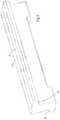
- FIG. 1 and 2show a base coupling member 1 and Figs. 3 and 4 show an intermediate coupling member 2.
- the intermediate coupling member 2is an elongated body which comprises extensions 3. The extensions 3 slidably fit in cavities 4 of the base coupling member 1 whereas a back side 5 of the intermediate coupling member 2 slidably fits to a guide 6.
- Fig. 5illustrates a situation in which several intermediate coupling members 2 are slidably fit to the base coupling member 1. In this case the elongated bodies of the intermediate coupling members 2 are located behind each other in longitudinal direction thereof.
- Fig. 6shows a cross-sectional view of two panels 7 which are part of the embodiment of the panel coupling assembly 9 according to the invention.
- the typical shapes of adjacent side edges 8 of the panels 7will be clarified hereinafter.
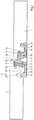
- Fig. 7illustrates the panel coupling assembly 9 in a non-assembled condition at the left side of the drawing and in an assembled condition at the right side of the drawing.
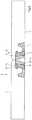
- Fig. 8an entirely assembled condition of both panels 7 is shown.
- the embodiment of the assembly 9is formed by two base coupling members that are integrated in a single base coupling member 1 which can receive intermediate coupling members 2 at opposite sides thereof for fixing two adjacent panels 7 thereto. It is also possible that in an alternative embodiment the assembly comprises only a half of the base coupling member 1 accommodating a single intermediate coupling member 2 for fixing a single panel 7 thereto. Such an alternative embodiment can be used near a wall where the flooring ends.
- the panels 7have horizontally oriented grooves which are arranged parallel to their side edges 8.
- the panels 7may comprise a laminate of a core and at least a decorative upper layer.
- the side edge 8 of the panel 7comprises an activating portion 10 which is directed to a panel fixing direction X, see Fig. 7 .
- the panel fixing direction Xis the direction in which the panel 7 is displaced with respect to the base coupling member 1 in order to attach the panel 7 to the base coupling member 1.
- the base coupling member 1is placed on the ground with a bottom side 11 thereof, whereas the fixing direction X is directed downwardly.
- the intermediate coupling member 2is displaceable with respect to the panel 7 horizontally and the base coupling member 1 downwardly in the non-assembled condition.
- the intermediate coupling member 2is provided with a sleeve portion 12 which faces to the activating portion 10 of the panel 7.
- the activating portion 10presses onto the sleeve portion 12 which results in a downward displacement of the intermediate coupling member 2.
- Due to the orientation of the guide 6the intermediate coupling member 2 is also displaced in horizontal direction and slides along an upper wall of the groove in the side edge 8, in this embodiment in a direction away from the base coupling member 1 towards the corresponding panel 7.
- the guide 6is angled with respect to an upper face of the panel 7. The guide angle can be 20-30° with respect to the upper face of the panel 7.
- the panel coupling assembly 9is also provided with a fixing element 13.
- the fixing element 13comprises a resilient lip mounted to the base coupling member 1.
- the fixing element 13is engageable to the intermediate coupling member 2.
- the intermediate coupling member 2 and the fixing element 13together form a locking member 2, 13 that engages the panel 7 and the base coupling member 1 such that the panel 7 is locked with respect to the base coupling member 1 in a direction opposite to the panel fixing direction X.
- the panel 7is locked in upward direction with respect to the base coupling member 1 via the intermediate coupling member 2 and the fixing element 13.
- the intermediate coupling member 2In the assembled condition the intermediate coupling member 2 is engaged to the panel 7 at a location where a first intermediate coupling member contact portion 14 and a first panel contact portion 15 contact each other, whereas the fixing element 13 is engaged to the intermediate coupling member 2 at a location where a second intermediate coupling member contact portion 16 and a fixing element contact portion 17 contact each other. It is noted that in this case the sleeve portion 12, the first intermediate coupling member contact portion 14 and the second intermediate coupling member contact portion 16 are spaced from each other.
- the fixing element 13 and the intermediate coupling member 2comprise a snap-in connection, which is formed by a resilient lip which is integral with the base coupling member 1.
- the fixing element 13is bent inwardly such that the intermediate coupling member 2 can displace further downwardly.
- the fixing element 13returns and moves outwardly such that it engages the intermediate coupling member 2.
- both the intermediate coupling member 2 and the fixing element 13are provided with cams to achieve this phenomenon.
- the cams and other parts of the assembly 9are shaped such that in the assembled or snapped condition the activating portion 10 of the panel 7 and the sleeve portion 12 of the intermediate coupling member 2 are free from each other. Due to the extensions 3 of the intermediate coupling member 2 which are received in cavities 4 the intermediate coupling member 2 is hold to the guide 6 upon bending the cam of the fixing element 13 inwardly.
- the intermediate coupling member 2has two tongues protruding in opposite horizontal directions. As described hereinbefore the tongues have associated functions.
- the upper oneprovides the first intermediate coupling member contact portion 14 at a lower side thereof for preventing the panel 7 from displacing upwardly with respect to the base coupling member 1
- the lower tongueprovides the second intermediate coupling member contact portion 16 which hooks behind a cam of the fixing element 13 in order to prevent the intermediate coupling member 2 from displacing upwardly with respect to the base coupling member 1.
- the side edges 8 of the panels 7are provided with a groove for receiving the upper tongue of the intermediate coupling member 2.
- the outwardly protruding cam of the fixing element 13is located such that in the non-assembled condition it supports the intermediate coupling member 2.
- the resiliency of the fixing element 13is such that without exerting pressure onto the sleeve portion 12 the intermediate coupling member 2 is hold in the position as illustrated in the left part of Fig. 7 . This avoids the situation that the intermediate coupling member 2 moves downwardly too far such that the upper tongue thereof has already moved away from the base coupling member 1 towards the panel 7 before panel 7 is pressed onto the intermediate coupling member 2.
- first intermediate coupling member contact portion 14 and the first panel contact portion 15are angled upwardly as seen in the horizontal direction in which the intermediate coupling member 2 is displaced during assembly. This provides a progressive down force onto the panel 7 upon assembling. Besides, the first intermediate coupling member contact portion 14 also provides a horizontal force on the panel 7.
- the panel 7is also locked in the panel fixing direction at a contact location between a second panel contact portion 18 that is directed in the panel fixing direction X and an associated base coupling member contact portion 19 that is directed in opposite direction of the panel fixing direction X.
- the second panel contact portion 18 and the base coupling member contact portion 19may be flat or angled with respect to the upper face of the panel 7.
- the base coupling member 1is provided with an upwardly directed lip 20 which fits in a vertically oriented groove 21 of the panel 7.
- the lip 20provides a lip contact portion 22 that is directed transversely with respect to the panel fixing direction X and which contacts a third panel contact portion 23.
- the first intermediate coupling member contact portion 14 and the lip contact portion 22clamp a downwardly protruding panel lip 24 in horizontal direction.
- the third panel contact portion 23may be angled at 55-65° with respect to the upper face of the panel 7.
- clamping of the panel 7 in horizontal directioncan also be achieved by the lip contact portion 22 and an upper side edge portion 25 of an adjacent panel 7. This is advantageous in terms of closing any gaps between the upper side edge portions 25 of adjacent panels 7, hence minimizing any penetration of dirt or moisture between the panels 7.
- the panel 7 and the intermediate coupling member 2are displaceable with respect to each other in a direction extending transversely with respect to the fixing direction X in the non-assembled condition.
- Fig. 7in which it can be seen that the left panel is displaceable horizontally with respect to the intermediate coupling member 2 and the base coupling member 1.
- the third panel contact portion 23may be guided along the lip contact portion 22, hence being displaced in horizontal direction, as well.
- the dimensions and orientations of the different parts as described abovecan be selected such that detaching the panel 7 from the base coupling member 1 is possible by exerting an upward force on the panel 7. If all sides of one panel are formed like the embodiment of Fig. 7 and corresponding base coupling members 1 and intermediate coupling members 2 are present, the panel 7 can be taken out a flooring separately, i.e. without detaching adjacent panels 7.
- the panels 7may have different shapes, for example rectangular, square or the like.
- the side edges 8 as shown in the figuresmay be present at one or more sides of the panel 7. If the shape of the side edge 8 is present at the entire circumference of the panel 7 and the panel 7 is entirely attachable to the base coupling member 1, it can be attached or detached in the middle of a flooring.
- Fig. 9ashows a cross-sectional view of the base coupling member 1 including the reference signs that indicate relevant portions of the base coupling member 1 as described hereinbefore.
- Fig. 9bshows a view at the same longitudinal location as Fig. 9a of the base coupling member 1 including two intermediate coupling members 2. In this situation the lower tongues of the intermediate coupling members 2 rest on the outwardly protruding cams of the fixing elements 13. The extensions 3 are accommodated in the cavities 4.
- Fig. 9dshows the situation in which the lower tongues of the intermediate coupling members 2 are hooked behind the cams of the fixing elements 13.
- Fig. 9cshows a view at a different longitudinal location than that shown in Figs. 9a and 9b in order to illustrate that the back side 5 of the intermediate coupling member 5 slides along the guide 6.
- the guideis adapted such that the intermediate coupling member is displaced in the direction of the base coupling member during assembly and engages thereto in the assembled condition, whereas the fixing element locks the intermediate coupling member with respect to the panel.
Landscapes
- Engineering & Computer Science (AREA)
- Architecture (AREA)
- Civil Engineering (AREA)
- Structural Engineering (AREA)
- Physics & Mathematics (AREA)
- Electromagnetism (AREA)
- Connection Of Plates (AREA)
- Floor Finish (AREA)
- Joining Of Building Structures In Genera (AREA)
- Details Of Connecting Devices For Male And Female Coupling (AREA)
- Connector Housings Or Holding Contact Members (AREA)
Description
- The invention relates to a panel coupling assembly.
- Several types of panel coupling assemblies are known in the art. For example,
EP 1 119 671EP 1 119 671WO 00/20706 - The object of the invention is to provide an improved panel coupling assembly.
- This object is accomplished with the panel coupling assembly according to
claim 1. - Due to the presence of the intermediate coupling member it is possible to lock the panel with respect to the base coupling member in the opposite direction of the panel fixing direction because of its displacement in transverse direction thereto. The intermediate coupling is guided to a position in the assembled condition whereas the fixing element holds the intermediate coupling member in that position with respect to the panel and the base coupling member in the assembled condition. The displacement of the intermediate coupling member in transverse direction provides the opportunity to hook it behind a wall extending transversely to the panel fixing direction, for example. It is noted that the panel may be displaceable in transverse direction with respect tot the intermediate coupling and/or the base coupling, as well, during the non-assembled condition or a part of the assembly operation.
- Furthermore, the intermediate coupling member and the base coupling member may be made of plastic. The intermediate coupling member may be a rigid body. The intermediate coupling member is a separate part, which may be coupled to the base coupling member by the user or which is already coupled thereto during manufacturing.
- In practice, the base coupling member may be located on the ground whereas the panel fixing direction is directed downwardly.
- In a practical embodiment the intermediate coupling member is engaged to the panel, and the fixing element is engaged to the base coupling member in the assembled condition. This means that during assembling the intermediate coupling member engages the panel whereas the fixing element forms a coupling between the intermediate coupling member and the base coupling member.
- The assembly may be adapted such that upon displacing the panel with respect to the base coupling member in the panel fixing direction the intermediate coupling member is displaced in the fixing direction. In this embodiment the intermediate coupling member is displaced both in the fixing direction and the direction extending transversely thereto.
- The fixing element and the intermediate coupling member may comprise a snap-in connection which can be activated by displacing the panel with respect to the base coupling member beyond a predefined position.
- The snap-in connection may be formed by a resilient lip at the base coupling member which engages a cam on the intermediate coupling member. This means that the fixing element is integrated in the base coupling member which minimizes the number of parts of the panel coupling assembly.
- In a specific embodiment the assembly is adapted such that the activating portion of the panel and the sleeve portion of the intermediate coupling member are substantially free from each other in the assembled condition. In this case the activating portion and the sleeve portion are only used to bring the assembly from the non-assembled condition to the assembled condition, whereas other mutual contact portions of the parts are used for holding the parts of the assembly together in the assembled condition.
- Preferably, the guide is provided at the base coupling member for guiding the intermediate coupling member with respect thereto, since this gives the base coupling member still another function.
- The guide may be angled with respect to an upped face of the panel in the assembled condition. For example, the angle lies between 60 and 80 degrees.
- The guide may be provided with a guide coupling which is adapted such that the intermediate coupling member is moveable with respect to the base coupling member in only one dimension. This avoids the situation that the base coupling member is pressed away from the guide during assembly, particularly in case of activating the snap-in connection.
- The intermediate coupling member may be provided with a tongue extending in a direction transversely with respect to the panel fixing direction and the side edge or the panel may be provided with a groove for receiving the tongue, wherein a lower portion of the tongue forms a first intermediate coupling member contact portion which engages a first panel contact portion being a bottom portion of said groove. This can be manufactured relatively simple.
- The first intermediate coupling member contact portion and the first panel contact portion may be angled with respect to an upper face of the panel. This provides the opportunity to lock the panel with respect to the base coupling member not only in a direction opposite to the panel fixing direction, but also in a direction transversely thereto. The base coupling member may be provided with a clamping portion facing to the first intermediate coupling member contact portion such that a portion of the panel can be clamped between the clamping portion and the first intermediate coupling member contact portion, for example.
- The assembly may comprise two integrated base coupling members, two intermediate coupling members and two panels for attaching two adjacent panels to said integrated base coupling members. The base coupling member or the integrated base coupling members can be made in one piece, for example by moulding.
- The invention will be explained in more detail hereinafter with reference to drawings, which are schematic representations of an embodiment of the invention.
Fig. 1 is a perspective top view of a base coupling member of an embodiment of a panel coupling assembly according to the invention.Fig. 2 is a similar view asFig. 1 as seen from a different side.Fig. 3 is a perspective view of an intermediate coupling member of the embodiment of a panel coupling assembly according to the invention.Fig. 4 is a similar view asFig. 3 as seen from a different side.Fig. 5 is a similar view asFig. 2 , but illustrating the base coupling member to which several intermediate coupling members are coupled.Fig. 6 is a cross-sectional view of adjacent panels of the embodiment of a panel coupling assembly.Fig. 7 is a similar view asFig. 6 including the base coupling member and two intermediate coupling members in partly assembled condition.Fig. 8 is a similar view asFig. 7 illustrating an entirely assembled condition.Fig. 9 is a series of different cross-sectional views illustrating different positions of the intermediate coupling members with respect to the base coupling member.- Separate parts of an embodiment of a panel coupling assembly according to the invention are shown in perspective views in
Figs. 1-4 .Figs. 1 and2 show abase coupling member 1 andFigs. 3 and4 show anintermediate coupling member 2. As shown inFig. 4 theintermediate coupling member 2 is an elongated body which comprisesextensions 3. Theextensions 3 slidably fit incavities 4 of thebase coupling member 1 whereas aback side 5 of theintermediate coupling member 2 slidably fits to aguide 6.Fig. 5 illustrates a situation in which severalintermediate coupling members 2 are slidably fit to thebase coupling member 1. In this case the elongated bodies of theintermediate coupling members 2 are located behind each other in longitudinal direction thereof. Fig. 6 shows a cross-sectional view of twopanels 7 which are part of the embodiment of thepanel coupling assembly 9 according to the invention. The typical shapes ofadjacent side edges 8 of thepanels 7 will be clarified hereinafter.Fig. 7 illustrates thepanel coupling assembly 9 in a non-assembled condition at the left side of the drawing and in an assembled condition at the right side of the drawing. InFig. 8 an entirely assembled condition of bothpanels 7 is shown.- In fact the embodiment of the
assembly 9 is formed by two base coupling members that are integrated in a singlebase coupling member 1 which can receiveintermediate coupling members 2 at opposite sides thereof for fixing twoadjacent panels 7 thereto. It is also possible that in an alternative embodiment the assembly comprises only a half of thebase coupling member 1 accommodating a singleintermediate coupling member 2 for fixing asingle panel 7 thereto. Such an alternative embodiment can be used near a wall where the flooring ends. - The
panels 7 have horizontally oriented grooves which are arranged parallel to theirside edges 8. In practice thepanels 7 may comprise a laminate of a core and at least a decorative upper layer. - Focussing in more detail on the embodiment of the
panel coupling assembly 9 as shown in the figures, theside edge 8 of thepanel 7 comprises an activatingportion 10 which is directed to a panel fixing direction X, seeFig. 7 . The panel fixing direction X is the direction in which thepanel 7 is displaced with respect to thebase coupling member 1 in order to attach thepanel 7 to thebase coupling member 1. In this case thebase coupling member 1 is placed on the ground with abottom side 11 thereof, whereas the fixing direction X is directed downwardly. - As illustrated in
Fig. 7 theintermediate coupling member 2 is displaceable with respect to thepanel 7 horizontally and thebase coupling member 1 downwardly in the non-assembled condition. Theintermediate coupling member 2 is provided with asleeve portion 12 which faces to the activatingportion 10 of thepanel 7. When thepanel 7 is displaced downwardly the activatingportion 10 presses onto thesleeve portion 12 which results in a downward displacement of theintermediate coupling member 2. Due to the orientation of theguide 6 theintermediate coupling member 2 is also displaced in horizontal direction and slides along an upper wall of the groove in theside edge 8, in this embodiment in a direction away from thebase coupling member 1 towards the correspondingpanel 7. As can be seen inFig. 7 theguide 6 is angled with respect to an upper face of thepanel 7. The guide angle can be 20-30° with respect to the upper face of thepanel 7. - The
panel coupling assembly 9 is also provided with a fixingelement 13. In this embodiment the fixingelement 13 comprises a resilient lip mounted to thebase coupling member 1. The fixingelement 13 is engageable to theintermediate coupling member 2. In the assembled condition as shown in the right part ofFig. 7 theintermediate coupling member 2 and the fixingelement 13 together form a lockingmember panel 7 and thebase coupling member 1 such that thepanel 7 is locked with respect to thebase coupling member 1 in a direction opposite to the panel fixing direction X. In other words thepanel 7 is locked in upward direction with respect to thebase coupling member 1 via theintermediate coupling member 2 and the fixingelement 13. - In the assembled condition the
intermediate coupling member 2 is engaged to thepanel 7 at a location where a first intermediate couplingmember contact portion 14 and a firstpanel contact portion 15 contact each other, whereas the fixingelement 13 is engaged to theintermediate coupling member 2 at a location where a second intermediate couplingmember contact portion 16 and a fixingelement contact portion 17 contact each other. It is noted that in this case thesleeve portion 12, the first intermediate couplingmember contact portion 14 and the second intermediate couplingmember contact portion 16 are spaced from each other. - In the embodiment as shown in
Fig. 7 the fixingelement 13 and theintermediate coupling member 2 comprise a snap-in connection, which is formed by a resilient lip which is integral with thebase coupling member 1. When thepanel 7 is moved downwardly during assembling, the fixingelement 13 is bent inwardly such that theintermediate coupling member 2 can displace further downwardly. When theintermediate coupling member 2 has passed a predefined position with respect to the fixingelement 13 the fixingelement 13 returns and moves outwardly such that it engages theintermediate coupling member 2. As shown inFig. 7 both theintermediate coupling member 2 and the fixingelement 13 are provided with cams to achieve this phenomenon.Fig. 7 also shows that the cams and other parts of theassembly 9 are shaped such that in the assembled or snapped condition the activatingportion 10 of thepanel 7 and thesleeve portion 12 of theintermediate coupling member 2 are free from each other. Due to theextensions 3 of theintermediate coupling member 2 which are received incavities 4 theintermediate coupling member 2 is hold to theguide 6 upon bending the cam of the fixingelement 13 inwardly. - It is noted that the
intermediate coupling member 2 has two tongues protruding in opposite horizontal directions. As described hereinbefore the tongues have associated functions. The upper one provides the first intermediate couplingmember contact portion 14 at a lower side thereof for preventing thepanel 7 from displacing upwardly with respect to thebase coupling member 1, whereas the lower tongue provides the second intermediate couplingmember contact portion 16 which hooks behind a cam of the fixingelement 13 in order to prevent theintermediate coupling member 2 from displacing upwardly with respect to thebase coupling member 1. The side edges 8 of thepanels 7 are provided with a groove for receiving the upper tongue of theintermediate coupling member 2. - The outwardly protruding cam of the fixing
element 13 is located such that in the non-assembled condition it supports theintermediate coupling member 2. The resiliency of the fixingelement 13 is such that without exerting pressure onto thesleeve portion 12 theintermediate coupling member 2 is hold in the position as illustrated in the left part ofFig. 7 . This avoids the situation that theintermediate coupling member 2 moves downwardly too far such that the upper tongue thereof has already moved away from thebase coupling member 1 towards thepanel 7 beforepanel 7 is pressed onto theintermediate coupling member 2. - In the embodiment as shown in the figures the first intermediate coupling
member contact portion 14 and the firstpanel contact portion 15 are angled upwardly as seen in the horizontal direction in which theintermediate coupling member 2 is displaced during assembly. This provides a progressive down force onto thepanel 7 upon assembling. Besides, the first intermediate couplingmember contact portion 14 also provides a horizontal force on thepanel 7. - The
panel 7 is also locked in the panel fixing direction at a contact location between a secondpanel contact portion 18 that is directed in the panel fixing direction X and an associated base couplingmember contact portion 19 that is directed in opposite direction of the panel fixing direction X. The secondpanel contact portion 18 and the base couplingmember contact portion 19 may be flat or angled with respect to the upper face of thepanel 7. - The
base coupling member 1 is provided with an upwardly directedlip 20 which fits in a vertically orientedgroove 21 of thepanel 7. Thelip 20 provides alip contact portion 22 that is directed transversely with respect to the panel fixing direction X and which contacts a thirdpanel contact portion 23. The first intermediate couplingmember contact portion 14 and thelip contact portion 22 clamp a downwardly protrudingpanel lip 24 in horizontal direction. The thirdpanel contact portion 23 may be angled at 55-65° with respect to the upper face of thepanel 7. - Alternatively, clamping of the
panel 7 in horizontal direction can also be achieved by thelip contact portion 22 and an upperside edge portion 25 of anadjacent panel 7. This is advantageous in terms of closing any gaps between the upperside edge portions 25 ofadjacent panels 7, hence minimizing any penetration of dirt or moisture between thepanels 7. - It is noted that the
panel 7 and theintermediate coupling member 2 are displaceable with respect to each other in a direction extending transversely with respect to the fixing direction X in the non-assembled condition. This is shown inFig. 7 in which it can be seen that the left panel is displaceable horizontally with respect to theintermediate coupling member 2 and thebase coupling member 1. For example, during the downward movement of thepanel 7 the thirdpanel contact portion 23 may be guided along thelip contact portion 22, hence being displaced in horizontal direction, as well. - It is conceivable that during the manufacturing process of parts of the
panel coupling assembly 9 theintermediate coupling members 2 are already fit in thebase coupling member 1. It is also possible that onepanel 7 is already attached to thebase coupling member 1, whereas only the other one has to be attached upon laying the flooring. - The dimensions and orientations of the different parts as described above can be selected such that detaching the
panel 7 from thebase coupling member 1 is possible by exerting an upward force on thepanel 7. If all sides of one panel are formed like the embodiment ofFig. 7 and correspondingbase coupling members 1 andintermediate coupling members 2 are present, thepanel 7 can be taken out a flooring separately, i.e. without detachingadjacent panels 7. - The
panels 7 may have different shapes, for example rectangular, square or the like. The side edges 8 as shown in the figures may be present at one or more sides of thepanel 7. If the shape of theside edge 8 is present at the entire circumference of thepanel 7 and thepanel 7 is entirely attachable to thebase coupling member 1, it can be attached or detached in the middle of a flooring. Fig. 9a shows a cross-sectional view of thebase coupling member 1 including the reference signs that indicate relevant portions of thebase coupling member 1 as described hereinbefore.Fig. 9b shows a view at the same longitudinal location asFig. 9a of thebase coupling member 1 including twointermediate coupling members 2. In this situation the lower tongues of theintermediate coupling members 2 rest on the outwardly protruding cams of the fixingelements 13. Theextensions 3 are accommodated in thecavities 4.Fig. 9d shows the situation in which the lower tongues of theintermediate coupling members 2 are hooked behind the cams of the fixingelements 13.Fig. 9c shows a view at a different longitudinal location than that shown inFigs. 9a and 9b in order to illustrate that theback side 5 of theintermediate coupling member 5 slides along theguide 6.- The invention is not limited to the embodiments shown in the figures, which can be varied in several ways within the scope of the invention as defined by the appended claims. It is for example possible that the guide is adapted such that the intermediate coupling member is displaced in the direction of the base coupling member during assembly and engages thereto in the assembled condition, whereas the fixing element locks the intermediate coupling member with respect to the panel.
Claims (14)
- A panel coupling assembly (9) comprising
a panel (7) including a side edge (8) which is provided with an activating portion (10) directed to a panel fixing direction (X),
a base coupling member (1),
an intermediate coupling member (2) being displaceable with respect to the panel (7) and the base coupling member (1) in a non-assembled condition and which is provided with a sleeve portion (12) facing to the activating portion (10) of the panel (7),
a guide (6) for guiding the intermediate coupling member (2) from a position in the non-assembled condition to a position in an assembled condition of the panel coupling assembly (9), which guide (6) is adapted such that upon displacing the panel (7) with respect to the base coupling member (1) in the panel fixing direction (X) the activating portion (10) of the panel (7) presses onto the sleeve portion (12) and the intermediate coupling member (2) is displaced in at least a direction extending transversely to the panel fixing direction (X),
a fixing element (13) being engageable to the intermediate coupling member (2) such that in the assembled condition the intermediate coupling member (2) and the fixing element (13) together form a locking member (2, 13) that couples the panel (7) and the base coupling member (1) such that the panel (7) is locked with respect to the base coupling member (1) in a direction opposite to the panel fixing direction (X),characterized in that the intermediate coupling member (2) is a separate part. - A panel coupling assembly (9) according to claim 1, wherein the intermediate coupling member (2) is engaged to the panel (7), and the fixing element (13) is engaged to the base coupling member (1) in the assembled condition.
- A panel coupling assembly (9) according to claim 1 or 2, wherein the assembly (9) is adapted such that upon displacing the panel (7) with respect to the base coupling member (1) in the panel fixing direction (X) the intermediate coupling member (2) is at least displaced in the fixing direction (X).
- A panel coupling assembly (9) according to one of the preceding claims, wherein the fixing element (13) and the intermediate coupling member (2) comprise a snap-in connection which can be activated by displacing the panel (7) with respect to the base coupling member (1) beyond a predefined position.
- A panel coupling assembly (9) according to claim 4, wherein the snap-in connection is formed by a resilient lip at the base coupling member (1) which engages a cam on the intermediate coupling member (2).
- A panel coupling assembly (9) according to one of the preceding claims, wherein the assembly (9) is adapted such that the activating portion (10) of the panel (7) and the sleeve portion (12) of the intermediate coupling member (2) are substantially free from each other in the assembled condition.
- A panel coupling assembly (9) according to one of the preceding claims, wherein the base coupling member (1) is located on the ground and the panel fixing direction (X) is directed downwardly.
- A panel coupling assembly (9) according to one of the preceding claims, wherein the guide (6) is provided at the base coupling member (1) for guiding the intermediate coupling member (2) with respect thereto.
- A panel coupling assembly (9) according to one of the preceding claims, wherein the guide (6) is angled with respect to an upper face of the panel (7) in the assembled condition.
- A panel coupling assembly (9) according to claim 9, wherein the angle lies between 60 and 80 degrees.
- A panel coupling assembly (9) according to one of the preceding claims, wherein the guide (6) is provided with a guide coupling (3, 4) which is adapted such that the intermediate coupling member is moveable with respect to the base coupling member (1) in only one dimension.
- A panel coupling assembly (9) according to one of the preceding claims, wherein the intermediate coupling member (2) is provided with a tongue extending in a direction transversely with respect to the panel fixing direction (X) and the side edge (8) of the panel (7) is provided with a groove for receiving the tongue, wherein a lower portion of the tongue forms a first intermediate coupling member contact portion (14) which engages a first panel contact portion (15) being a bottom portion of said groove.
- A panel coupling assembly (9) according to claim 12, wherein the first intermediate coupling member contact portion (14) and the first panel contact portion (15) are angled with respect to an upper face of the panel (7).
- A panel coupling assembly (9) according to one of the preceding claims, wherein the assembly (9) comprises two integrated base coupling members (1), two intermediate coupling members (2) and two panels (7) for attaching two adjacent panels (7) to said integrated base coupling members (1).
Priority Applications (7)
| Application Number | Priority Date | Filing Date | Title |
|---|---|---|---|
| EP10166253.4AEP2397623B1 (en) | 2010-06-17 | 2010-06-17 | A panel coupling assembly |
| BR112012032014-9ABR112012032014B1 (en) | 2010-06-17 | 2011-06-15 | panel coupling assembly |
| CN201180039639.5ACN103119231B (en) | 2010-06-17 | 2011-06-15 | Plate coupling assembling |
| PCT/EP2011/059946WO2011157752A1 (en) | 2010-06-17 | 2011-06-15 | A panel coupling assembly |
| CA2802966ACA2802966C (en) | 2010-06-17 | 2011-06-15 | A panel coupling assembly |
| RU2012157166/03ARU2564334C2 (en) | 2010-06-17 | 2011-06-15 | Panel connection device |
| US13/704,842US8813454B2 (en) | 2010-06-17 | 2011-06-15 | Panel coupling assembly |
Applications Claiming Priority (1)
| Application Number | Priority Date | Filing Date | Title |
|---|---|---|---|
| EP10166253.4AEP2397623B1 (en) | 2010-06-17 | 2010-06-17 | A panel coupling assembly |
Publications (2)
| Publication Number | Publication Date |
|---|---|
| EP2397623A1 EP2397623A1 (en) | 2011-12-21 |
| EP2397623B1true EP2397623B1 (en) | 2018-01-31 |
Family
ID=42953833
Family Applications (1)
| Application Number | Title | Priority Date | Filing Date |
|---|---|---|---|
| EP10166253.4ANot-in-forceEP2397623B1 (en) | 2010-06-17 | 2010-06-17 | A panel coupling assembly |
Country Status (7)
| Country | Link |
|---|---|
| US (1) | US8813454B2 (en) |
| EP (1) | EP2397623B1 (en) |
| CN (1) | CN103119231B (en) |
| BR (1) | BR112012032014B1 (en) |
| CA (1) | CA2802966C (en) |
| RU (1) | RU2564334C2 (en) |
| WO (1) | WO2011157752A1 (en) |
Families Citing this family (24)
| Publication number | Priority date | Publication date | Assignee | Title |
|---|---|---|---|---|
| BR112012017589B1 (en) | 2010-01-14 | 2019-11-12 | Spanolux N V Div Balterio | floor panel mounting |
| CN102844506B (en) | 2010-04-15 | 2015-08-12 | 巴尔特利奥-斯巴诺吕克斯股份公司 | floor components |
| EP2397623B1 (en)* | 2010-06-17 | 2018-01-31 | Unilin, BVBA | A panel coupling assembly |
| US8806832B2 (en) | 2011-03-18 | 2014-08-19 | Inotec Global Limited | Vertical joint system and associated surface covering system |
| UA114715C2 (en) | 2011-07-05 | 2017-07-25 | Сералок Інновейшн Аб | Mechanical locking of floor panels with a glued tongue |
| US9725912B2 (en) | 2011-07-11 | 2017-08-08 | Ceraloc Innovation Ab | Mechanical locking system for floor panels |
| US8650826B2 (en) | 2011-07-19 | 2014-02-18 | Valinge Flooring Technology Ab | Mechanical locking system for floor panels |
| US8857126B2 (en) | 2011-08-15 | 2014-10-14 | Valinge Flooring Technology Ab | Mechanical locking system for floor panels |
| PL2923012T3 (en) | 2012-11-22 | 2020-04-30 | Ceraloc Innovation Ab | Mechanical locking system for floor panels |
| US8745949B1 (en)* | 2013-04-12 | 2014-06-10 | Chao Kang Pien | Method and apparatus for flooring |
| PT3014034T (en) | 2013-06-27 | 2019-11-29 | Vaelinge Innovation Ab | Building panel with a mechanical locking system |
| KR102314032B1 (en) | 2013-10-25 | 2021-10-15 | 세라록 이노베이션 에이비 | Mechanical locking system for floor panels |
| US10246883B2 (en)* | 2014-05-14 | 2019-04-02 | Valinge Innovation Ab | Building panel with a mechanical locking system |
| CN106460394B (en)* | 2014-05-14 | 2019-09-17 | 瓦林格创新股份有限公司 | Building panel with mechanical locking system |
| FR3026796B1 (en)* | 2014-10-02 | 2017-03-03 | Peugeot Citroen Automobiles Sa | SOLISARIZATION SYSTEM BETWEEN AN ORGAN EQUIPPED WITH A MOTOR VEHICLE AND A CHASSIS OF THE MOTOR VEHICLE. |
| JP6900313B2 (en) | 2014-11-27 | 2021-07-07 | ベーリンゲ、イノベイション、アクチボラグVaelinge Innovation Ab | Mechanical locking system for floor panels |
| CN106032696B (en)* | 2015-03-18 | 2019-03-08 | 杨凤玲 | Splice floor board |
| CN104831927B (en)* | 2015-04-29 | 2017-01-04 | 浙江未来加电子商务有限公司 | A kind of plug-in type bulk surface layer ground paving equipment, method |
| WO2017185167A1 (en)* | 2016-04-26 | 2017-11-02 | Les Plafonds Embassy Inc. | Clip for suspended ceiling members |
| US11208812B2 (en)* | 2018-06-13 | 2021-12-28 | Ceraloc Innovation Ab | Flooring system provided with a connecting system and an associated connecting device |
| CN108888242A (en)* | 2018-08-09 | 2018-11-27 | 深圳迈瑞生物医疗电子股份有限公司 | Plug-in type monitor and card module for plug-in type monitor |
| US11060302B2 (en) | 2019-01-10 | 2021-07-13 | Valinge Innovation Ab | Unlocking system for panels |
| DE202021003901U1 (en)* | 2021-12-30 | 2022-02-09 | Surface Technologies Gmbh & Co. Kg | Set of two panels to cover a surface and a panel connector, panel connector and use of a panel connector |
| USD1082495S1 (en)* | 2023-12-21 | 2025-07-08 | Välinge Innovation AB | Clip for floor panels |
Family Cites Families (13)
| Publication number | Priority date | Publication date | Assignee | Title |
|---|---|---|---|---|
| DE2021503A1 (en)* | 1970-05-02 | 1971-11-25 | Freudenberg Carl Fa | Floor panels and methods of joining them |
| SE513189C2 (en) | 1998-10-06 | 2000-07-24 | Perstorp Flooring Ab | Vertically mountable floor covering material comprising sheet-shaped floor elements which are joined together by means of separate joint profiles |
| SE514645C2 (en)* | 1998-10-06 | 2001-03-26 | Perstorp Flooring Ab | Floor covering material comprising disc-shaped floor elements intended to be joined by separate joint profiles |
| SE522860C2 (en)* | 2000-03-10 | 2004-03-09 | Pergo Europ Ab | Vertically joined floor elements comprising a combination of different floor elements |
| ATE467015T1 (en)* | 2002-04-03 | 2010-05-15 | Vaelinge Innovation Ab | FLOOR PANEL WITH INTEGRATED CONNECTING MEANS AND METHOD FOR THE PRODUCTION THEREOF |
| DE10297810D2 (en)* | 2002-08-19 | 2005-07-07 | Peter Kellner | Floor of individual elements |
| US7841144B2 (en)* | 2005-03-30 | 2010-11-30 | Valinge Innovation Ab | Mechanical locking system for panels and method of installing same |
| SE529664C2 (en)* | 2005-07-11 | 2007-10-16 | Pergo Europ Ab | A joint profile for a panel |
| CN1757856A (en)* | 2005-11-11 | 2006-04-12 | 圣象实业(深圳)有限公司 | Plate material with bar shaped fastener capable of mutually locked |
| ITMC20060041A1 (en)* | 2006-04-20 | 2007-10-21 | Cristian Sorini | MODULAR EQUIPMENT FOR THE REALIZATION OF HORIZONTAL OR VERTICAL LINES EASILY REMOVABLE. |
| SE530048C2 (en)* | 2006-06-09 | 2008-02-19 | Burseryd Innovation Ab | Fasteners and method of joining dynamic bodies by means of the fastener |
| FR2906285A1 (en)* | 2006-09-22 | 2008-03-28 | Jean Pierre Grau | Modular floor covering, has floor element including housing that vertically fits and unfits floor element on assembly element, where housing receives tenon of assembly element arranged on mounting surface of floor element |
| EP2397623B1 (en)* | 2010-06-17 | 2018-01-31 | Unilin, BVBA | A panel coupling assembly |
- 2010
- 2010-06-17EPEP10166253.4Apatent/EP2397623B1/ennot_activeNot-in-force
- 2011
- 2011-06-15USUS13/704,842patent/US8813454B2/ennot_activeExpired - Fee Related
- 2011-06-15RURU2012157166/03Apatent/RU2564334C2/ennot_activeIP Right Cessation
- 2011-06-15CNCN201180039639.5Apatent/CN103119231B/ennot_activeExpired - Fee Related
- 2011-06-15WOPCT/EP2011/059946patent/WO2011157752A1/enactiveApplication Filing
- 2011-06-15BRBR112012032014-9Apatent/BR112012032014B1/ennot_activeIP Right Cessation
- 2011-06-15CACA2802966Apatent/CA2802966C/ennot_activeExpired - Fee Related
Non-Patent Citations (1)
| Title |
|---|
| None* |
Also Published As
| Publication number | Publication date |
|---|---|
| BR112012032014B1 (en) | 2019-11-19 |
| CA2802966A1 (en) | 2011-12-22 |
| WO2011157752A1 (en) | 2011-12-22 |
| EP2397623A1 (en) | 2011-12-21 |
| CN103119231A (en) | 2013-05-22 |
| RU2012157166A (en) | 2014-07-27 |
| CN103119231B (en) | 2015-10-21 |
| BR112012032014A2 (en) | 2016-11-08 |
| US20130167467A1 (en) | 2013-07-04 |
| US8813454B2 (en) | 2014-08-26 |
| RU2564334C2 (en) | 2015-09-27 |
| CA2802966C (en) | 2018-09-04 |
Similar Documents
| Publication | Publication Date | Title |
|---|---|---|
| EP2397623B1 (en) | A panel coupling assembly | |
| US10612249B2 (en) | Floor panel for forming a floor covering, floor covering formed from such floor panels and method for manufacturing such floor panels | |
| US8720148B2 (en) | Set of panels | |
| KR102058467B1 (en) | Mechanical locking system for floor panels | |
| US10006211B2 (en) | Flooring system having assembly clip and related method | |
| EP3176345B1 (en) | Floor panel and floor covering consisting of a plurality of such floor panels | |
| CZ304961B6 (en) | Panel elements | |
| KR101450476B1 (en) | A fixing apparatus for synthetic wood | |
| CN108368703A (en) | Panel set for floor, wall or ceiling coverings | |
| US8763335B2 (en) | Wainscoting system | |
| EP1790795A1 (en) | Floor System | |
| JP3125484U (en) | Assembly floor unit | |
| KR20140043291A (en) | Structure for connecting members with hidden engaging portion and connection device for the same |
Legal Events
| Date | Code | Title | Description |
|---|---|---|---|
| AK | Designated contracting states | Kind code of ref document:A1 Designated state(s):AL AT BE BG CH CY CZ DE DK EE ES FI FR GB GR HR HU IE IS IT LI LT LU LV MC MK MT NL NO PL PT RO SE SI SK SM TR | |
| AX | Request for extension of the european patent | Extension state:BA ME RS | |
| PUAI | Public reference made under article 153(3) epc to a published international application that has entered the european phase | Free format text:ORIGINAL CODE: 0009012 | |
| 17P | Request for examination filed | Effective date:20120619 | |
| RAP1 | Party data changed (applicant data changed or rights of an application transferred) | Owner name:UNILIN, BVBA | |
| 17Q | First examination report despatched | Effective date:20170626 | |
| GRAP | Despatch of communication of intention to grant a patent | Free format text:ORIGINAL CODE: EPIDOSNIGR1 | |
| RIC1 | Information provided on ipc code assigned before grant | Ipc:E04C 2/38 20060101ALI20170814BHEP Ipc:E04F 15/02 20060101AFI20170814BHEP | |
| INTG | Intention to grant announced | Effective date:20170915 | |
| GRAS | Grant fee paid | Free format text:ORIGINAL CODE: EPIDOSNIGR3 | |
| GRAA | (expected) grant | Free format text:ORIGINAL CODE: 0009210 | |
| AK | Designated contracting states | Kind code of ref document:B1 Designated state(s):AL AT BE BG CH CY CZ DE DK EE ES FI FR GB GR HR HU IE IS IT LI LT LU LV MC MK MT NL NO PL PT RO SE SI SK SM TR | |
| REG | Reference to a national code | Ref country code:GB Ref legal event code:FG4D Ref country code:CH Ref legal event code:EP | |
| REG | Reference to a national code | Ref country code:AT Ref legal event code:REF Ref document number:967533 Country of ref document:AT Kind code of ref document:T Effective date:20180215 | |
| REG | Reference to a national code | Ref country code:IE Ref legal event code:FG4D | |
| REG | Reference to a national code | Ref country code:DE Ref legal event code:R096 Ref document number:602010048330 Country of ref document:DE | |
| REG | Reference to a national code | Ref country code:NL Ref legal event code:MP Effective date:20180131 | |
| REG | Reference to a national code | Ref country code:LT Ref legal event code:MG4D | |
| REG | Reference to a national code | Ref country code:AT Ref legal event code:MK05 Ref document number:967533 Country of ref document:AT Kind code of ref document:T Effective date:20180131 | |
| REG | Reference to a national code | Ref country code:FR Ref legal event code:PLFP Year of fee payment:9 | |
| PG25 | Lapsed in a contracting state [announced via postgrant information from national office to epo] | Ref country code:NO Free format text:LAPSE BECAUSE OF FAILURE TO SUBMIT A TRANSLATION OF THE DESCRIPTION OR TO PAY THE FEE WITHIN THE PRESCRIBED TIME-LIMIT Effective date:20180430 Ref country code:ES Free format text:LAPSE BECAUSE OF FAILURE TO SUBMIT A TRANSLATION OF THE DESCRIPTION OR TO PAY THE FEE WITHIN THE PRESCRIBED TIME-LIMIT Effective date:20180131 Ref country code:LT Free format text:LAPSE BECAUSE OF FAILURE TO SUBMIT A TRANSLATION OF THE DESCRIPTION OR TO PAY THE FEE WITHIN THE PRESCRIBED TIME-LIMIT Effective date:20180131 Ref country code:FI Free format text:LAPSE BECAUSE OF FAILURE TO SUBMIT A TRANSLATION OF THE DESCRIPTION OR TO PAY THE FEE WITHIN THE PRESCRIBED TIME-LIMIT Effective date:20180131 Ref country code:NL Free format text:LAPSE BECAUSE OF FAILURE TO SUBMIT A TRANSLATION OF THE DESCRIPTION OR TO PAY THE FEE WITHIN THE PRESCRIBED TIME-LIMIT Effective date:20180131 Ref country code:HR Free format text:LAPSE BECAUSE OF FAILURE TO SUBMIT A TRANSLATION OF THE DESCRIPTION OR TO PAY THE FEE WITHIN THE PRESCRIBED TIME-LIMIT Effective date:20180131 | |
| PG25 | Lapsed in a contracting state [announced via postgrant information from national office to epo] | Ref country code:IS Free format text:LAPSE BECAUSE OF FAILURE TO SUBMIT A TRANSLATION OF THE DESCRIPTION OR TO PAY THE FEE WITHIN THE PRESCRIBED TIME-LIMIT Effective date:20180531 Ref country code:BG Free format text:LAPSE BECAUSE OF FAILURE TO SUBMIT A TRANSLATION OF THE DESCRIPTION OR TO PAY THE FEE WITHIN THE PRESCRIBED TIME-LIMIT Effective date:20180430 Ref country code:AT Free format text:LAPSE BECAUSE OF FAILURE TO SUBMIT A TRANSLATION OF THE DESCRIPTION OR TO PAY THE FEE WITHIN THE PRESCRIBED TIME-LIMIT Effective date:20180131 Ref country code:LV Free format text:LAPSE BECAUSE OF FAILURE TO SUBMIT A TRANSLATION OF THE DESCRIPTION OR TO PAY THE FEE WITHIN THE PRESCRIBED TIME-LIMIT Effective date:20180131 Ref country code:GR Free format text:LAPSE BECAUSE OF FAILURE TO SUBMIT A TRANSLATION OF THE DESCRIPTION OR TO PAY THE FEE WITHIN THE PRESCRIBED TIME-LIMIT Effective date:20180501 Ref country code:SE Free format text:LAPSE BECAUSE OF FAILURE TO SUBMIT A TRANSLATION OF THE DESCRIPTION OR TO PAY THE FEE WITHIN THE PRESCRIBED TIME-LIMIT Effective date:20180131 Ref country code:PL Free format text:LAPSE BECAUSE OF FAILURE TO SUBMIT A TRANSLATION OF THE DESCRIPTION OR TO PAY THE FEE WITHIN THE PRESCRIBED TIME-LIMIT Effective date:20180131 | |
| PG25 | Lapsed in a contracting state [announced via postgrant information from national office to epo] | Ref country code:EE Free format text:LAPSE BECAUSE OF FAILURE TO SUBMIT A TRANSLATION OF THE DESCRIPTION OR TO PAY THE FEE WITHIN THE PRESCRIBED TIME-LIMIT Effective date:20180131 Ref country code:RO Free format text:LAPSE BECAUSE OF FAILURE TO SUBMIT A TRANSLATION OF THE DESCRIPTION OR TO PAY THE FEE WITHIN THE PRESCRIBED TIME-LIMIT Effective date:20180131 Ref country code:AL Free format text:LAPSE BECAUSE OF FAILURE TO SUBMIT A TRANSLATION OF THE DESCRIPTION OR TO PAY THE FEE WITHIN THE PRESCRIBED TIME-LIMIT Effective date:20180131 | |
| REG | Reference to a national code | Ref country code:DE Ref legal event code:R097 Ref document number:602010048330 Country of ref document:DE | |
| PG25 | Lapsed in a contracting state [announced via postgrant information from national office to epo] | Ref country code:SM Free format text:LAPSE BECAUSE OF FAILURE TO SUBMIT A TRANSLATION OF THE DESCRIPTION OR TO PAY THE FEE WITHIN THE PRESCRIBED TIME-LIMIT Effective date:20180131 Ref country code:DK Free format text:LAPSE BECAUSE OF FAILURE TO SUBMIT A TRANSLATION OF THE DESCRIPTION OR TO PAY THE FEE WITHIN THE PRESCRIBED TIME-LIMIT Effective date:20180131 Ref country code:SK Free format text:LAPSE BECAUSE OF FAILURE TO SUBMIT A TRANSLATION OF THE DESCRIPTION OR TO PAY THE FEE WITHIN THE PRESCRIBED TIME-LIMIT Effective date:20180131 Ref country code:CZ Free format text:LAPSE BECAUSE OF FAILURE TO SUBMIT A TRANSLATION OF THE DESCRIPTION OR TO PAY THE FEE WITHIN THE PRESCRIBED TIME-LIMIT Effective date:20180131 | |
| PLBE | No opposition filed within time limit | Free format text:ORIGINAL CODE: 0009261 | |
| STAA | Information on the status of an ep patent application or granted ep patent | Free format text:STATUS: NO OPPOSITION FILED WITHIN TIME LIMIT | |
| 26N | No opposition filed | Effective date:20181102 | |
| REG | Reference to a national code | Ref country code:CH Ref legal event code:PL | |
| GBPC | Gb: european patent ceased through non-payment of renewal fee | Effective date:20180617 | |
| PG25 | Lapsed in a contracting state [announced via postgrant information from national office to epo] | Ref country code:SI Free format text:LAPSE BECAUSE OF FAILURE TO SUBMIT A TRANSLATION OF THE DESCRIPTION OR TO PAY THE FEE WITHIN THE PRESCRIBED TIME-LIMIT Effective date:20180131 | |
| REG | Reference to a national code | Ref country code:BE Ref legal event code:MM Effective date:20180630 | |
| REG | Reference to a national code | Ref country code:IE Ref legal event code:MM4A | |
| PG25 | Lapsed in a contracting state [announced via postgrant information from national office to epo] | Ref country code:LU Free format text:LAPSE BECAUSE OF NON-PAYMENT OF DUE FEES Effective date:20180617 Ref country code:MC Free format text:LAPSE BECAUSE OF FAILURE TO SUBMIT A TRANSLATION OF THE DESCRIPTION OR TO PAY THE FEE WITHIN THE PRESCRIBED TIME-LIMIT Effective date:20180131 | |
| PG25 | Lapsed in a contracting state [announced via postgrant information from national office to epo] | Ref country code:GB Free format text:LAPSE BECAUSE OF NON-PAYMENT OF DUE FEES Effective date:20180617 Ref country code:IE Free format text:LAPSE BECAUSE OF NON-PAYMENT OF DUE FEES Effective date:20180617 Ref country code:CH Free format text:LAPSE BECAUSE OF NON-PAYMENT OF DUE FEES Effective date:20180630 Ref country code:LI Free format text:LAPSE BECAUSE OF NON-PAYMENT OF DUE FEES Effective date:20180630 | |
| PG25 | Lapsed in a contracting state [announced via postgrant information from national office to epo] | Ref country code:BE Free format text:LAPSE BECAUSE OF NON-PAYMENT OF DUE FEES Effective date:20180630 | |
| PGFP | Annual fee paid to national office [announced via postgrant information from national office to epo] | Ref country code:IT Payment date:20190621 Year of fee payment:10 | |
| PGFP | Annual fee paid to national office [announced via postgrant information from national office to epo] | Ref country code:FR Payment date:20190625 Year of fee payment:10 Ref country code:TR Payment date:20190612 Year of fee payment:10 | |
| PGFP | Annual fee paid to national office [announced via postgrant information from national office to epo] | Ref country code:DE Payment date:20190627 Year of fee payment:10 | |
| PG25 | Lapsed in a contracting state [announced via postgrant information from national office to epo] | Ref country code:MT Free format text:LAPSE BECAUSE OF NON-PAYMENT OF DUE FEES Effective date:20180617 | |
| PG25 | Lapsed in a contracting state [announced via postgrant information from national office to epo] | Ref country code:PT Free format text:LAPSE BECAUSE OF FAILURE TO SUBMIT A TRANSLATION OF THE DESCRIPTION OR TO PAY THE FEE WITHIN THE PRESCRIBED TIME-LIMIT Effective date:20180131 Ref country code:HU Free format text:LAPSE BECAUSE OF FAILURE TO SUBMIT A TRANSLATION OF THE DESCRIPTION OR TO PAY THE FEE WITHIN THE PRESCRIBED TIME-LIMIT; INVALID AB INITIO Effective date:20100617 | |
| PG25 | Lapsed in a contracting state [announced via postgrant information from national office to epo] | Ref country code:MK Free format text:LAPSE BECAUSE OF NON-PAYMENT OF DUE FEES Effective date:20180131 Ref country code:CY Free format text:LAPSE BECAUSE OF FAILURE TO SUBMIT A TRANSLATION OF THE DESCRIPTION OR TO PAY THE FEE WITHIN THE PRESCRIBED TIME-LIMIT Effective date:20180131 | |
| REG | Reference to a national code | Ref country code:DE Ref legal event code:R119 Ref document number:602010048330 Country of ref document:DE | |
| PG25 | Lapsed in a contracting state [announced via postgrant information from national office to epo] | Ref country code:FR Free format text:LAPSE BECAUSE OF NON-PAYMENT OF DUE FEES Effective date:20200630 | |
| PG25 | Lapsed in a contracting state [announced via postgrant information from national office to epo] | Ref country code:DE Free format text:LAPSE BECAUSE OF NON-PAYMENT OF DUE FEES Effective date:20210101 | |
| PG25 | Lapsed in a contracting state [announced via postgrant information from national office to epo] | Ref country code:IT Free format text:LAPSE BECAUSE OF NON-PAYMENT OF DUE FEES Effective date:20200617 | |
| PG25 | Lapsed in a contracting state [announced via postgrant information from national office to epo] | Ref country code:TR Free format text:LAPSE BECAUSE OF NON-PAYMENT OF DUE FEES Effective date:20200617 |