EP2395933B1 - Ablation catheter for electrically isolating cardiac tissue - Google Patents
Ablation catheter for electrically isolating cardiac tissueDownload PDFInfo
- Publication number
- EP2395933B1 EP2395933B1EP09776388.2AEP09776388AEP2395933B1EP 2395933 B1EP2395933 B1EP 2395933B1EP 09776388 AEP09776388 AEP 09776388AEP 2395933 B1EP2395933 B1EP 2395933B1
- Authority
- EP
- European Patent Office
- Prior art keywords
- distal end
- electrodes
- elongate member
- direct current
- ablation catheter
- Prior art date
- Legal status (The legal status is an assumption and is not a legal conclusion. Google has not performed a legal analysis and makes no representation as to the accuracy of the status listed.)
- Active
Links
- 238000002679ablationMethods0.000titleclaimsdescription32
- 210000005003heart tissueAnatomy0.000titledescription20
- 230000035939shockEffects0.000claimsdescription59
- 230000033764rhythmic processEffects0.000claimsdescription8
- 210000001519tissueAnatomy0.000description72
- 238000000034methodMethods0.000description20
- 210000003492pulmonary veinAnatomy0.000description20
- 238000002955isolationMethods0.000description13
- 210000005246left atriumAnatomy0.000description13
- 210000003462veinAnatomy0.000description11
- 210000002837heart atriumAnatomy0.000description8
- 230000001746atrial effectEffects0.000description5
- 210000005245right atriumAnatomy0.000description5
- 210000002027skeletal muscleAnatomy0.000description5
- 238000013194cardioversionMethods0.000description4
- 230000000295complement effectEffects0.000description4
- 206010003658Atrial FibrillationDiseases0.000description3
- 206010061592cardiac fibrillationDiseases0.000description3
- 230000002600fibrillogenic effectEffects0.000description3
- 239000000203mixtureSubstances0.000description3
- 210000004165myocardiumAnatomy0.000description3
- 210000005166vasculatureAnatomy0.000description3
- 206010003130Arrhythmia supraventricularDiseases0.000description2
- 230000006378damageEffects0.000description2
- 230000000694effectsEffects0.000description2
- 210000003238esophagusAnatomy0.000description2
- 230000003176fibrotic effectEffects0.000description2
- 210000005248left atrial appendageAnatomy0.000description2
- 239000000463materialSubstances0.000description2
- 238000005259measurementMethods0.000description2
- 238000012544monitoring processMethods0.000description2
- 238000012546transferMethods0.000description2
- 210000001631vena cava inferiorAnatomy0.000description2
- 208000007536ThrombosisDiseases0.000description1
- 230000015572biosynthetic processEffects0.000description1
- 230000002498deadly effectEffects0.000description1
- 230000007423decreaseEffects0.000description1
- 239000007933dermal patchSubstances0.000description1
- 201000010099diseaseDiseases0.000description1
- 208000037265diseases, disorders, signs and symptomsDiseases0.000description1
- 238000006073displacement reactionMethods0.000description1
- 238000005516engineering processMethods0.000description1
- 230000002708enhancing effectEffects0.000description1
- 238000004880explosionMethods0.000description1
- 238000010438heat treatmentMethods0.000description1
- 230000001939inductive effectEffects0.000description1
- 230000003902lesionEffects0.000description1
- 230000004807localizationEffects0.000description1
- 230000007257malfunctionEffects0.000description1
- 238000013507mappingMethods0.000description1
- 210000003205muscleAnatomy0.000description1
- 230000001902propagating effectEffects0.000description1
- 238000000718qrs complexMethods0.000description1
- 238000007674radiofrequency ablationMethods0.000description1
- 210000005241right ventricleAnatomy0.000description1
- 239000000758substrateSubstances0.000description1
- 238000012360testing methodMethods0.000description1
- 230000000451tissue damageEffects0.000description1
- 231100000827tissue damageToxicity0.000description1
- 230000001052transient effectEffects0.000description1
- 238000002604ultrasonographyMethods0.000description1
- 208000003663ventricular fibrillationDiseases0.000description1
Images


Classifications
- A—HUMAN NECESSITIES
- A61—MEDICAL OR VETERINARY SCIENCE; HYGIENE
- A61B—DIAGNOSIS; SURGERY; IDENTIFICATION
- A61B18/00—Surgical instruments, devices or methods for transferring non-mechanical forms of energy to or from the body
- A61B18/04—Surgical instruments, devices or methods for transferring non-mechanical forms of energy to or from the body by heating
- A61B18/12—Surgical instruments, devices or methods for transferring non-mechanical forms of energy to or from the body by heating by passing a current through the tissue to be heated, e.g. high-frequency current
- A61B18/14—Probes or electrodes therefor
- A61B18/1492—Probes or electrodes therefor having a flexible, catheter-like structure, e.g. for heart ablation
- A—HUMAN NECESSITIES
- A61—MEDICAL OR VETERINARY SCIENCE; HYGIENE
- A61B—DIAGNOSIS; SURGERY; IDENTIFICATION
- A61B17/00—Surgical instruments, devices or methods
- A61B17/00234—Surgical instruments, devices or methods for minimally invasive surgery
- A61B2017/00292—Surgical instruments, devices or methods for minimally invasive surgery mounted on or guided by flexible, e.g. catheter-like, means
- A61B2017/003—Steerable
- A—HUMAN NECESSITIES
- A61—MEDICAL OR VETERINARY SCIENCE; HYGIENE
- A61B—DIAGNOSIS; SURGERY; IDENTIFICATION
- A61B17/00—Surgical instruments, devices or methods
- A61B2017/00831—Material properties
- A61B2017/00867—Material properties shape memory effect
- A—HUMAN NECESSITIES
- A61—MEDICAL OR VETERINARY SCIENCE; HYGIENE
- A61B—DIAGNOSIS; SURGERY; IDENTIFICATION
- A61B18/00—Surgical instruments, devices or methods for transferring non-mechanical forms of energy to or from the body
- A61B2018/00053—Mechanical features of the instrument of device
- A61B2018/0016—Energy applicators arranged in a two- or three dimensional array
- A—HUMAN NECESSITIES
- A61—MEDICAL OR VETERINARY SCIENCE; HYGIENE
- A61B—DIAGNOSIS; SURGERY; IDENTIFICATION
- A61B18/00—Surgical instruments, devices or methods for transferring non-mechanical forms of energy to or from the body
- A61B2018/00315—Surgical instruments, devices or methods for transferring non-mechanical forms of energy to or from the body for treatment of particular body parts
- A61B2018/00345—Vascular system
- A61B2018/00351—Heart
- A61B2018/00375—Ostium, e.g. ostium of pulmonary vein or artery
- A—HUMAN NECESSITIES
- A61—MEDICAL OR VETERINARY SCIENCE; HYGIENE
- A61B—DIAGNOSIS; SURGERY; IDENTIFICATION
- A61B18/00—Surgical instruments, devices or methods for transferring non-mechanical forms of energy to or from the body
- A61B2018/00636—Sensing and controlling the application of energy
- A61B2018/00696—Controlled or regulated parameters
- A61B2018/00761—Duration
- A—HUMAN NECESSITIES
- A61—MEDICAL OR VETERINARY SCIENCE; HYGIENE
- A61B—DIAGNOSIS; SURGERY; IDENTIFICATION
- A61B18/00—Surgical instruments, devices or methods for transferring non-mechanical forms of energy to or from the body
- A61B2018/00636—Sensing and controlling the application of energy
- A61B2018/00773—Sensed parameters
- A61B2018/00839—Bioelectrical parameters, e.g. ECG, EEG
- A—HUMAN NECESSITIES
- A61—MEDICAL OR VETERINARY SCIENCE; HYGIENE
- A61B—DIAGNOSIS; SURGERY; IDENTIFICATION
- A61B18/00—Surgical instruments, devices or methods for transferring non-mechanical forms of energy to or from the body
- A61B18/04—Surgical instruments, devices or methods for transferring non-mechanical forms of energy to or from the body by heating
- A61B18/12—Surgical instruments, devices or methods for transferring non-mechanical forms of energy to or from the body by heating by passing a current through the tissue to be heated, e.g. high-frequency current
- A61B18/1206—Generators therefor
- A61B2018/1246—Generators therefor characterised by the output polarity
- A61B2018/1253—Generators therefor characterised by the output polarity monopolar
- A—HUMAN NECESSITIES
- A61—MEDICAL OR VETERINARY SCIENCE; HYGIENE
- A61B—DIAGNOSIS; SURGERY; IDENTIFICATION
- A61B18/00—Surgical instruments, devices or methods for transferring non-mechanical forms of energy to or from the body
- A61B18/04—Surgical instruments, devices or methods for transferring non-mechanical forms of energy to or from the body by heating
- A61B18/12—Surgical instruments, devices or methods for transferring non-mechanical forms of energy to or from the body by heating by passing a current through the tissue to be heated, e.g. high-frequency current
- A61B18/1206—Generators therefor
- A61B2018/1246—Generators therefor characterised by the output polarity
- A61B2018/126—Generators therefor characterised by the output polarity bipolar
- A—HUMAN NECESSITIES
- A61—MEDICAL OR VETERINARY SCIENCE; HYGIENE
- A61B—DIAGNOSIS; SURGERY; IDENTIFICATION
- A61B18/00—Surgical instruments, devices or methods for transferring non-mechanical forms of energy to or from the body
- A61B18/04—Surgical instruments, devices or methods for transferring non-mechanical forms of energy to or from the body by heating
- A61B18/12—Surgical instruments, devices or methods for transferring non-mechanical forms of energy to or from the body by heating by passing a current through the tissue to be heated, e.g. high-frequency current
- A61B18/1206—Generators therefor
- A61B2018/1266—Generators therefor with DC current output
- A—HUMAN NECESSITIES
- A61—MEDICAL OR VETERINARY SCIENCE; HYGIENE
- A61B—DIAGNOSIS; SURGERY; IDENTIFICATION
- A61B18/00—Surgical instruments, devices or methods for transferring non-mechanical forms of energy to or from the body
- A61B18/04—Surgical instruments, devices or methods for transferring non-mechanical forms of energy to or from the body by heating
- A61B18/12—Surgical instruments, devices or methods for transferring non-mechanical forms of energy to or from the body by heating by passing a current through the tissue to be heated, e.g. high-frequency current
- A61B18/1206—Generators therefor
- A61B2018/1273—Generators therefor including multiple generators in one device
- A—HUMAN NECESSITIES
- A61—MEDICAL OR VETERINARY SCIENCE; HYGIENE
- A61B—DIAGNOSIS; SURGERY; IDENTIFICATION
- A61B18/00—Surgical instruments, devices or methods for transferring non-mechanical forms of energy to or from the body
- A61B18/04—Surgical instruments, devices or methods for transferring non-mechanical forms of energy to or from the body by heating
- A61B18/12—Surgical instruments, devices or methods for transferring non-mechanical forms of energy to or from the body by heating by passing a current through the tissue to be heated, e.g. high-frequency current
- A61B18/14—Probes or electrodes therefor
- A61B2018/1405—Electrodes having a specific shape
- A61B2018/1407—Loop
- A—HUMAN NECESSITIES
- A61—MEDICAL OR VETERINARY SCIENCE; HYGIENE
- A61B—DIAGNOSIS; SURGERY; IDENTIFICATION
- A61B18/00—Surgical instruments, devices or methods for transferring non-mechanical forms of energy to or from the body
- A61B18/04—Surgical instruments, devices or methods for transferring non-mechanical forms of energy to or from the body by heating
- A61B18/12—Surgical instruments, devices or methods for transferring non-mechanical forms of energy to or from the body by heating by passing a current through the tissue to be heated, e.g. high-frequency current
- A61B18/14—Probes or electrodes therefor
- A61B2018/1465—Deformable electrodes
- A—HUMAN NECESSITIES
- A61—MEDICAL OR VETERINARY SCIENCE; HYGIENE
- A61B—DIAGNOSIS; SURGERY; IDENTIFICATION
- A61B18/00—Surgical instruments, devices or methods for transferring non-mechanical forms of energy to or from the body
- A61B18/04—Surgical instruments, devices or methods for transferring non-mechanical forms of energy to or from the body by heating
- A61B18/12—Surgical instruments, devices or methods for transferring non-mechanical forms of energy to or from the body by heating by passing a current through the tissue to be heated, e.g. high-frequency current
- A61B18/14—Probes or electrodes therefor
- A61B2018/1467—Probes or electrodes therefor using more than two electrodes on a single probe
- A—HUMAN NECESSITIES
- A61—MEDICAL OR VETERINARY SCIENCE; HYGIENE
- A61B—DIAGNOSIS; SURGERY; IDENTIFICATION
- A61B18/00—Surgical instruments, devices or methods for transferring non-mechanical forms of energy to or from the body
- A61B18/04—Surgical instruments, devices or methods for transferring non-mechanical forms of energy to or from the body by heating
- A61B18/12—Surgical instruments, devices or methods for transferring non-mechanical forms of energy to or from the body by heating by passing a current through the tissue to be heated, e.g. high-frequency current
- A61B18/14—Probes or electrodes therefor
- A61B2018/1475—Electrodes retractable in or deployable from a housing
- A—HUMAN NECESSITIES
- A61—MEDICAL OR VETERINARY SCIENCE; HYGIENE
- A61B—DIAGNOSIS; SURGERY; IDENTIFICATION
- A61B18/00—Surgical instruments, devices or methods for transferring non-mechanical forms of energy to or from the body
- A61B18/04—Surgical instruments, devices or methods for transferring non-mechanical forms of energy to or from the body by heating
- A61B18/12—Surgical instruments, devices or methods for transferring non-mechanical forms of energy to or from the body by heating by passing a current through the tissue to be heated, e.g. high-frequency current
- A61B18/14—Probes or electrodes therefor
- A61B2018/1497—Electrodes covering only part of the probe circumference
- A—HUMAN NECESSITIES
- A61—MEDICAL OR VETERINARY SCIENCE; HYGIENE
- A61B—DIAGNOSIS; SURGERY; IDENTIFICATION
- A61B18/00—Surgical instruments, devices or methods for transferring non-mechanical forms of energy to or from the body
- A61B18/04—Surgical instruments, devices or methods for transferring non-mechanical forms of energy to or from the body by heating
- A61B18/12—Surgical instruments, devices or methods for transferring non-mechanical forms of energy to or from the body by heating by passing a current through the tissue to be heated, e.g. high-frequency current
- A61B18/14—Probes or electrodes therefor
- A61B18/16—Indifferent or passive electrodes for grounding
- A61B2018/162—Indifferent or passive electrodes for grounding located on the probe body
- A—HUMAN NECESSITIES
- A61—MEDICAL OR VETERINARY SCIENCE; HYGIENE
- A61B—DIAGNOSIS; SURGERY; IDENTIFICATION
- A61B34/00—Computer-aided surgery; Manipulators or robots specially adapted for use in surgery
- A61B34/20—Surgical navigation systems; Devices for tracking or guiding surgical instruments, e.g. for frameless stereotaxis
- A—HUMAN NECESSITIES
- A61—MEDICAL OR VETERINARY SCIENCE; HYGIENE
- A61N—ELECTROTHERAPY; MAGNETOTHERAPY; RADIATION THERAPY; ULTRASOUND THERAPY
- A61N1/00—Electrotherapy; Circuits therefor
- A61N1/18—Applying electric currents by contact electrodes
- A61N1/32—Applying electric currents by contact electrodes alternating or intermittent currents
- A61N1/38—Applying electric currents by contact electrodes alternating or intermittent currents for producing shock effects
- A61N1/39—Heart defibrillators
- A61N1/395—Heart defibrillators for treating atrial fibrillation
- C—CHEMISTRY; METALLURGY
- C08—ORGANIC MACROMOLECULAR COMPOUNDS; THEIR PREPARATION OR CHEMICAL WORKING-UP; COMPOSITIONS BASED THEREON
- C08L—COMPOSITIONS OF MACROMOLECULAR COMPOUNDS
- C08L2201/00—Properties
- C08L2201/12—Shape memory
Definitions
- the present inventionrelates to an ablation catheter for electrically isolating cardiac tissue. More in particular, the invention relates to a catheter for use in a method for complete circular electrical isolation of the pulmonary vein ostia at their entrance to the left atrium.
- Pulmonary veinsare known sources or atrial arrhythmias and atrial fibrillation and the borders between the mouth (ostium) of the pulmonary veins and the left atrium (pulmonary vein antrum) are known areas with slow electrical conduction that may be part of the substrate that maintains atrial fibrillation once it has started. Complete electrical pulmonary vein antrum isolation may cure the disease in approximately 75% of patients. Electrical isolation through cardiac muscle can be achieved by causing permanent tissue damage that causes replacement of cardiac tissue by fibrotic tissue. In contrast to cardiac muscle, fibrotic tissue blocks a propagating electrical wave front and thus causes electrical isolation.
- Such techniquesinclude ablation by heating, for instance radiofrequency ablations or using ultrasound or laser energy, and cryo ablation.
- WO 2004/039273discloses a catheter with a single electrode for ablation using RF or DC energy.
- the ablation cathetercomprises an elongate member with proximal and distal ends, wherein the distal end comprises at least one electrode and is arranged to apply a high energy electrical shock from a plurality of locations along the length of said distal end and wherein said distal end is curved.
- the curved distal end of the elongate memberprovides a good contact between the tissue to be treated and the electrode.
- the curvature of the distal end of the elongate memberis adapted to the surface curvature of the tissue to be treated such that the curved distal end is substantially complementary to the surface of the tissue to be treated.
- the present inventionis based on the discovery that by using a DC ablation technique with a plurality of shock delivery locations which, due to the curvature of the distal end, are placed in close contact with the tissue to be treated, it is possible to efficiently isolate an area of tissue.
- the locationsextend along a path on the tissue and by applying a sufficiently high electrical shock to the distal end, the tissue areas contacting the delivery locations become permanently nonconductive.
- the need for repositioning the catheter multiple times for creating an electrical isolation between two areas of cardiac tissueis reduced.
- a relative long length of cardiac tissuecan be treated in a single operation, reducing the procedure time.
- high energy electrical shockas used herein should be interpreted as a shock applied during approximately 5 ms of between 200 and 500 Joule, preferably between 250 and 400 Joule and more preferably of approximately 350 Joule.
- the elongate memberis provided with suitable conducting means for conducting high energy electrical current from the proximal end of the elongate member to the distal end provided with the electrode.
- the guiding meanscomprise a guiding core provided in the elongate member.
- the distal end of the elongate memberextends in a circle segment. Since cardiac tissue surfaces are normally curved, providing a distal end with a substantially complementary shape in the form of a circle segment enhances the contact between the distal end provided with the at least one electrode and the tissue.
- the circle segmentfor instance allows a close fit of the distal end to at least a part of the cross section of the ostia of the pulmonary veins.
- the distal end of the elongate memberextends substantially circular.
- the distal endis hereby loop shaped.
- a tubular tissue surfacefor instance a vein, can be treated along a cross section in a single operation.
- the tissue areas extending adjacent said nonconductive tissueare isolated.
- the radius of the circle segmentis between 5 to 25 mm, preferably between 10 and 20 mm.
- the curvature of the distal endis adjustable, more specifically the diameter of the circle segment is adjustable. This allows a custom fit of the distal end of the elongate member to the surface of the tissue to be treated, regardless of the diameter or the curvature of said tissue.
- the curved distal end of the elongate memberextends in a plane under an angle with respect to the axis of the elongate member.
- the catheteris advanced along the longitudinal axis of said vessel.
- the electrode on the distal endextends in a plane under an angle with the axis of the elongate member, it is possible to efficiently contact the wall of said vessel at substantially any longitudinal location in said vessel.
- the curved distal end of the elongate memberextends in a plane substantially perpendicular to the axis of the elongate member.
- a length proximal to the distal end of the elongate memberis hereto preferably steerable. Using this steerable end, it is possible to adjust the orientation of the plane wherein the curved distal end extends to the surface of the tissue to be treated.
- the elongate memberis allowed to bend on a location proximal to the curvature of said distal end. This allows an efficient adjustment of the plane wherein said distal end extends.
- the distal end of the elongate membercomprises a plurality of electrodes extending at different locations along the length of said distal end.
- the shock delivery locations on the distal endare formed by separate electrodes.
- the electrodesextend at a mutual distance of between 3 and 12 mm, preferably at a distance of approximately 5 mm. A small mutual distance increases the homogeneous energy transfer the tissue and it was discovered that this results in a closed path of electrically nonconductive tissue when treated.
- the electrodesextend in a circle segment at substantially equal arc distances, allowing an efficient isolation of tissue in for instance a vessel.
- the distal endcomprises between 5 and 24 electrodes, preferably between 8 and 16 electrodes and more preferably the distal end comprises 10 electrodes. It was found that using ten electrodes, an optimal isolation of a vessel, for instance a pulmonary vein, can be achieved.
- the electrodeshave the same polarity. This allows an efficient distribution of the electrical energy from the electrodes provided on the distal end to the tissue to be treated.
- the electrodeswhen the electrodes extend in a circle segment, or more preferably in a circle, the radial outwardly distribution of the electrical energy is enhanced. Since the electrodes preferably engage the tissue with their surfaces facing radially outwardly with respect to the circle segment, the majority of the electrical energy is transferred to the tissue. It is furthermore advantageously when the electrodes comprise substantially smoothed surfaces, i.e. without any sharp edges. This prevents unwanted current concentrations around the electrodes.
- At least two adjacent electrodesare arranged to apply shocks with different voltages.
- the voltage of the applied shockalternates between adjacent electrodes. This allows a radial outwardly distribution of the electrical energy due the same polarity used for each of the electrodes, combined with a flow of electrical energy between two adjacent electrodes with different voltages.
- substantially all the tissue extending between said electrodesis subjected to said electrical energy, enhancing the isolating action.
- the elongate membercomprises conducting means arranged to separately conduct high electrical current to each of the electrodes from the proximal end to the distal end. This reduces the chance of high energy concentration near any of the individual electrodes in case of electrode malfunctions.
- Each of the electrodesis preferably fed separately using a suitable power source known in the art.
- the elongate memberis moveable between a first position wherein the elongate member extends substantially rectilinear and a second position wherein the distal end of the elongate member is curved.
- the straight orientation of the distal end in the first positionallows an efficient advancement of the catheter through for instance a sheath into the heart.
- the elongate membercan be moved to the second position wherein the distal end is curved and preferably extends in a circle segment.
- the elongate memberWhen use is made of sheath for advancing the elongate member though the vasculature, the elongate member can be advanced through the sheath when the sheath is in place.
- the sheathextends coaxial with respect to the elongate member and encloses the elongate member, preventing deflection of the distal end in the first position.
- the distal end of the elongate memberis hereto manufactured from a deflectable material. More preferably the distal end comprises shape memory. Advancing the elongate member out of the sheath will then automatically result in the movement from the first to the second position.
- the catheterfurther comprises an indifferent electrode extending proximal to the electrode. This significantly decreases the influence of the electrical shocks on the neighbouring tissue, for instance skeletal muscles.
- an integral indifferent electroderesults in a compact composition of the catheter according to the invention.
- the indifferent electrodecomprises a coil and more preferably the coil extends coaxial to the elongate member.
- the indifferent electrodeextends a distance of between 3 and 10 cm from the most proximal shock delivery location, and more preferably the indifferent electrode extends a distance of approximately 5 cm from the most proximal shock delivery location.
- the catheteris provided with a sheath, wherein the sheath is provided with the indifferent electrode.
- a sheathpreferably a steerable sheath
- the distal end of the sheathis usually advanced in the left atrium.
- the indifferent electrodepreferably a coil
- the indifferent electrodepreferably extends at a location with little skeletal muscle tissue in use, for instance in the right atrium or the inferior vena cava.
- a localization systemknown in the art to localize the catheter in the heart.
- the one electrode or the plurality of electrodes provided on the distal endcan then be localized in the heart.
- Such a systemfurthermore allows an accurate mapping of the heart, allowing an accurate deployment of the curved distal end on the heart tissue to be treated.
- the catheteris arranged to apply a high energy shock in dependence of the heart rhythm.
- Thisallows cardioversion, i.e. ending atrium fibrillation.
- the catheteris arranged to apply the shock outside the vulnerable phases in the heart rhythm of both the atrium and the ventricle. This enables cardioversion without inducing ventricle fibrillation.
- the electrode, or more preferably at least one of the plurality of electrodes, on the distal endis arranged to monitor the heart rhythm.
- the catheter of the inventionis provided with a suitable connector at the proximal end to connect the catheter to measurement means known in the art for monitoring the heart rhythm.
- the indifferent electrodeis located on the elongate member such that said electrode at least partially extends in another chamber, preferably in the right atrium, while the electrode on the distal end extends near the left atrium. This enhances the cardioversion since both poles, the indifferent electrode and the electrode on the distal end, extend in different chambers.
- a method for electrically isolating cardiac tissuecomprising the steps of:
- a plurality of shock delivery locationsis placed in close contact with the tissue to be treated wherein at least two locations extend at a mutual distance.
- the curvature of the distal end provided with the at least one electrodeprovides such close contact.
- the curvature of the distal end of the elongate memberis complementary to the surface of the tissue to be treated.
- the step of applying a high energy electrical shockcomprises applying a shock during a predetermined period of time of between 200 and 500 Joule, preferably between 250 and 400 Joule and more preferably of approximately 350 Joule. It was found that 350 Joule is enough for complete and permanent electrical isolation of the cardiac tissue.
- the predetermined period of timeis smaller than 10 ms, more preferably smaller than 5 ms and even more preferably the period of time is approximately 1 ms. Since the shock is delivered from a plurality of locations during a short period of time, the energy per unit of length is sufficiently small to prevent sparking and bubble forming associated with traditional direct current ablation.
- the distal endcomprises a plurality of electrodes, wherein the electrodes have the same polarity.
- the shock delivery locationsare formed by at least two separate electrodes at a mutual distance. Applying a shock from a plurality of electrodes with the same polarity allows an optimal distribution of the electrical energy.
- applying a high energy electrical shockcomprises simultaneously applying a shock from the plurality of electrodes. This furthermore enhances the distribution of the electrical energy to the tissue to be treated.
- a high energy electrical shockcomprises applying shocks with different voltages from at least two adjacent electrodes along the length of the distal end.
- the difference in voltage between two adjacent electrodesprovides a flow of electrical current between said electrodes.
- Next to the flow outwardly due to the same polarity of the electrodesat least a part of the electrical energy flows between adjacent electrodes. This ensures that substantially all tissue extending between the electrodes is subjected to electrical energy, resulting in a closed path of treated tissue.
- the voltages of the shock applied from the different electrodesalternates.
- the step of contacting the cardiac tissuemay comprise contacting the tissue along a path, wherein applying the shock comprises forming a closed path of electrically nonconducting tissue.
- the electrodesextend along a path on the tissue prior to the application of the shock. The distance between the electrodes is sufficiently small such that al tissue extending between two adjacent electrodes is subjected to sufficient electrical energy, resulting in a closed path of non-conductive tissue.
- the step of contacting the cardiac tissuecomprises adjusting the curvature of the distal end of elongate member to the surface of the cardiac tissue to be isolated.
- the shock delivery locations along the distal endfor instance the plurality of electrodes, can be placed in close proximity with the tissue, resulting in a more efficient energy transfer from the at least one electrode to the tissue.
- the distal end of the elongate memberextends in a circle segment, wherein the step of contacting comprises adjusting the diameter of the circle segment to the surface of the cardiac tissue. The diameter of the circle segment is adjusted to the diameter of the tissue to be treated, for instance to the inner diameter of a vessel.
- the step of contactingcomprises adjusting the plane wherein the curved segment extends to the surface of the cardiac tissue.
- the surface of the tissueextends under an angle with respect to for instance the longitudinal axis of the elongate member, it is possible to adjust the plane of the electrode(s) to enable a close fit of the distal end of the elongate member to said surface.
- the cathetercomprises a sheath, wherein advancing the catheter through the vasculature comprises advancing the catheter through the sheath, wherein the elongate member is moveable between a first position wherein the elongate member extends substantially rectilinear and a second position wherein the distal end of the elongate member is curved, wherein the elongate member moves from the first to the second position by advancing the elongate member out of the sheath.
- the elongate memberIn the first position the elongate member is restricted to deflect by the sheath enabling easy advancement of the elongate member through the sheath.
- the elongate memberwill move towards the second position and enables a close fit of the electrodes to the tissue.
- Applying a high electrical currentmay further comprise using an electrode provided on the catheter as indifferent electrode.
- the electrodecomprises a coil.
- external indifferent electrodesfor instance a skin patch, are associated with negative effects for the patients.
- the skeletal musclecontracts heavily during the shock and it often causes displacement of the patient on the catheterization table.
- Using an indifferent electrode provided on the catheterminimizes this problem.
- the cardiac tissuemay comprise pulmonary vein ostia, preferably pulmonary vein ostia near the entrance to the left atrium.
- Pulmonary veinsare known sources of atrial arrhythmias and atrial fibrillation.
- contacting the cardiac tissuecomprises contacting the ostia of the pulmonary vein with the distal end along a cross section of the vein. In this way a cross section of the pulmonary vein is made nonconductive, separating the tissue areas extending adjacent the nonconductive border.
- advancing to the cardiac tissuecomprises advancing the sheath provided with an indifferent electrode in the vicinity of the distal end extending in said atrium.
- Providing the indifferent electrode, for instance in the form of a coil, on the sheathallows a close relationship between the electrode(s) on the distal end and the indifferent electrode, minimizing the influence of the shock on the neighbouring tissue.
- the indifferent electrodeis located in use at a location with little skeletal muscle tissue, for instance the right atrium or the inferior vena cava.
- the methodmay further comprise the step of monitoring the heart rhythm and applying the shock in dependence of said heart rhythm.
- the ECGis measured at least prior to applying the shock.
- the ECG, and in particular the P-wave of said ECGis preferably measured using the electrode provided on the distal end of the catheter according to the invention. It is however also possible to use other measuring methods known to the person skilled in the art. Measuring the P-wave using external measuring methods is however difficult in some conditions. Measuring said P-wave using internal electrodes, for instance an electrode provided on the catheter or a separate catheter provided in the heart, allows a more reliable measurement.
- the shockis applied at a predetermined time in the heart rhythm outside the vulnerable phases of both the atria and the ventricles. Normally only the vulnerable phase of the ventricles is considered to prevent ventricular fibrillation.
- the energy shockis also applied outside the vulnerable phase of the atrium, preventing atrium fibrillation to occur when applying the shock. This furthermore allows efficient cardioversion.
- the energy shockis applied on or before the QRS-complex of the ECG.
- a catheter 1according to the invention is shown.
- the catheter 1comprises an elongate member 2 with a proximal end (not shown) and a distal end 21.
- the distal end 21 of the elongate memberis curved.
- the distal end 21extends in a circle segment, wherein the distal end 21 forms a loop or a lasso.
- the distal end 21extends in a plane II under an angle with respect to the longitudinal axis I of the elongate member 2.
- the distal end 21is provided with a plurality of electrodes 6, in this case ten.
- the electrodes 6extend on mutually distances of 5 mm.
- the distal end 21 of elongate member 2is steerable which allows the practitioner to adjust the plane II of the electrodes 6. This facilitates the placement of the electrodes on the tissue to be treated as will be explained in more detail below. Also shown is a steerable sheath 3, which allows an efficient advancement of the catheter 1 through the vasculature.
- the sheath 3is provided with an indifferent electrode in the form of a coil 7. The coil 7 is disposed coaxially to the sheath.
- the distal end 21 forming the loopis preferably manufactured from a deflectable material.
- the distal end 21will deform such that the distal end 21 will extend substantially rectilinear.
- the distal end 21is contained in the sheath 3. This results in a compact composition.
- the elongate member 2can be advanced through the sheath 3 to the tissue to be treated.
- the catheter 1is advanced to the tissue, the elongate member 21 is advanced out of the sheath 3, and the distal end 21 deflects back to the second position, as shown in figure 1 .
- the catheter 1is shown in place in the left atrium 8 of the heart.
- the sheath 3advanced through the septum 81.
- the coil 7hereby extends in the right atrium.
- the distal end 21 of the elongate member 2is advanced in said vein 82 such that the electrodes 6 contact the wall along a cross section of said vein 82.
- the most distal end 22is steerable, allowing the plane of the electrodes 6, indicated with II in figure 1 , to be adjusted in directions indicated with V and VI.
- the steerable most distal end 22it is also possible to adjust the diameter of the circle segment wherein the electrodes 6 extend, as is shown schematically in figure 3 .
- the distal end 21is advanced in a vein 82 it is possible that the electrodes 6 do not contact the tissue closely, as the case in figure 3 .
- the diametercan be adjusted.
- the electrodes 6are moved in a direction indicated with VI to achieve a close contact between the wall of the vein 82 and the electrodes 6.
- the distal end 21 provided with the electrodes 6forms a closed loop over a cross section of the vein 82.
- the electrodes 6extend over a closed loop over the inner wall of the vein, isolating the tissue areas extending adjacent the distal end 21 (below and above the plane of figure 3 ).
- the distance between two electrodes 6is sufficiently small to ensure that all tissue 83 extending between electrodes 6 is subjected to electrical energy sufficiently high to induce non-conductivity. This ensures a proper isolation.
- a curved surface of tissue 8is shown in figure 4 .
- the distal end 21is curved complementary to the curvature of the tissue 8. All of the electrodes 6 shown therefore make contact with the tissue 83. Due to the application of the shock through the electrodes 6, the tissue indicated with 83 is made nonconductive. This isolates the tissue indicated with 84a from the tissue indicated with 84b.
- the catheter 1is arranged to synchronously deliver a shock from the electrodes 6.
- Each of the electrodesis hereto provided with a separate power source known in the art. This results in a radially outwardly distribution of the electrical energy indicated with E1 in figure 5 .
- the term radialmust be interpreted with respect to the longitudinal axis I of the elongate member in the case where the distal end 21 extends in the plane II perpendicular to the axis I as shown in figures 1 and 2 .
- the electrodes 6are arranged to deliver a shock of an alternating voltage between the electrodes.
- the electrodes 6aare arranged to deliver a shock with a voltage of 3500V, while the electrodes 6b are arranged to deliver a shock of 3000V.
- This difference in voltage between adjacent electrodesresults in a flow of electrical energy E2 between the adjacent electrodes 6a and 6b. This ensures that tissue extending near the region 21a between the electrodes 6 is also sufficiently subjected to electrical energy E2.
- FIG 6a sketch of the reconstructed geometry of the left atrium of a pig is shown.
- the left atrium (LA), three pulmonary vein ostia (RPV, IPV and LPV) and part of the left atrial appendage (LAA)are shown.
- DC ablations according to the inventionwere performed in the ostia of the right RPV and left pulmonary veins LPV.
- the intention of the ablation procedureis to destroy all vital atrial myocardium inside the ostium of the pulmonary veins. Such destruction translates into a dramatic reduction of local electrograms, measured using endocardial catheters.
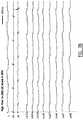
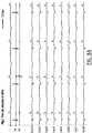
- Figure 7Ashows an electrocardiogram I of the pig's heart prior to ablation.
- RA and RVare electrograms of the right atrium and the right ventricle.
- La1-8are recordings from a lasso catheter in various positions in the atrium.
- a catheter according to the inventionhad been placed inside the ostium of the right pulmonary vein ostium in four different positions.
- One of the positionsis schematically drawn using a dotted line in figure 6 .
- a DC shock of 200 Joulehad been delivered via the ten electrodes of that catheter (20 Joule per electrode).
- the complete ostium of the right pulmonary veinonly shows very small electrogram amplitudes as can be seen from figure 7B , indicating the electrically active atrial tissue/muscle has been destroyed by the shocks.
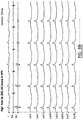
- Figure 8Aare the pre-recordings similar to the recordings shown in figure 7A for a second pig. In this case, two subsequent shocks of 200J were applied to the tissue. Also here, as can be seen from figure 7B , almost all atrial signals have disappeared, indicating that a lesion has been created in the ostium.
Landscapes
- Health & Medical Sciences (AREA)
- Life Sciences & Earth Sciences (AREA)
- Surgery (AREA)
- Engineering & Computer Science (AREA)
- Plasma & Fusion (AREA)
- Medical Informatics (AREA)
- Otolaryngology (AREA)
- Physics & Mathematics (AREA)
- Cardiology (AREA)
- Biomedical Technology (AREA)
- Heart & Thoracic Surgery (AREA)
- Nuclear Medicine, Radiotherapy & Molecular Imaging (AREA)
- Molecular Biology (AREA)
- Animal Behavior & Ethology (AREA)
- General Health & Medical Sciences (AREA)
- Public Health (AREA)
- Veterinary Medicine (AREA)
- Surgical Instruments (AREA)
Description
- The present invention relates to an ablation catheter for electrically isolating cardiac tissue. More in particular, the invention relates to a catheter for use in a method for complete circular electrical isolation of the pulmonary vein ostia at their entrance to the left atrium.
- Pulmonary veins are known sources or atrial arrhythmias and atrial fibrillation and the borders between the mouth (ostium) of the pulmonary veins and the left atrium (pulmonary vein antrum) are known areas with slow electrical conduction that may be part of the substrate that maintains atrial fibrillation once it has started. Complete electrical pulmonary vein antrum isolation may cure the disease in approximately 75% of patients. Electrical isolation through cardiac muscle can be achieved by causing permanent tissue damage that causes replacement of cardiac tissue by fibrotic tissue. In contrast to cardiac muscle, fibrotic tissue blocks a propagating electrical wave front and thus causes electrical isolation.
- At present, various techniques are used for pulmonary vein antrum isolation. Such techniques include ablation by heating, for instance radiofrequency ablations or using ultrasound or laser energy, and cryo ablation.
WO 2004/039273 ,EP 1042990 andUS 2004/0143256 for instance describe catheters for use in radiofrequency (RF) ablation procedures.WO 96/10950 - The abovementioned techniques all have their disadvantageous and drawbacks. Some are very time consuming, some require complex technology and very expensive, thick poorly steerable catheters and some often only cause transient electrical isolation with late recurrences. Some are risky because of the possible formation of blood clots or may cause esophageal fistulae, an often deadly leak between left atrial cavity and the esophagus due to damage to the wall of the esophagus which is very close to the posterior left atrial wall.
- It is an object of the invention to provide in a safe, efficient, and/or easy to use catheter for use in an ablation procedure, specifically for complete circular electrical isolation of the pulmonary vein ostia at their entrance to the left atrium.
- In order to accomplish that objective, a direct current ablation catheter is provided according to
claim 1. More specifically, the ablation catheter according to the invention comprises an elongate member with proximal and distal ends, wherein the distal end comprises at least one electrode and is arranged to apply a high energy electrical shock from a plurality of locations along the length of said distal end and wherein said distal end is curved. The curved distal end of the elongate member provides a good contact between the tissue to be treated and the electrode. Preferably the curvature of the distal end of the elongate member is adapted to the surface curvature of the tissue to be treated such that the curved distal end is substantially complementary to the surface of the tissue to be treated. - The present invention is based on the discovery that by using a DC ablation technique with a plurality of shock delivery locations which, due to the curvature of the distal end, are placed in close contact with the tissue to be treated, it is possible to efficiently isolate an area of tissue. The locations extend along a path on the tissue and by applying a sufficiently high electrical shock to the distal end, the tissue areas contacting the delivery locations become permanently nonconductive.
- Furthermore, by using a plurality of shock delivery locations in close contact with the tissue to be treated, the need for repositioning the catheter multiple times for creating an electrical isolation between two areas of cardiac tissue is reduced. With the device according to the invention, a relative long length of cardiac tissue can be treated in a single operation, reducing the procedure time.
- The term high energy electrical shock as used herein should be interpreted as a shock applied during approximately 5 ms of between 200 and 500 Joule, preferably between 250 and 400 Joule and more preferably of approximately 350 Joule. By applying the shock from a plurality of locations along the distal end, the energy is distributed over said length, limiting the energy per unit of length. The risk of explosions and sparking associated with DC ablation near the electrode is hereby reduced.
- In order to be able to deliver shocks at the distal end of the catheter, the elongate member is provided with suitable conducting means for conducting high energy electrical current from the proximal end of the elongate member to the distal end provided with the electrode. Preferably the guiding means comprise a guiding core provided in the elongate member.
- According to a preferred embodiment of the invention, the distal end of the elongate member extends in a circle segment. Since cardiac tissue surfaces are normally curved, providing a distal end with a substantially complementary shape in the form of a circle segment enhances the contact between the distal end provided with the at least one electrode and the tissue. The circle segment for instance allows a close fit of the distal end to at least a part of the cross section of the ostia of the pulmonary veins. Preferably the distal end of the elongate member extends substantially circular. The distal end is hereby loop shaped. Using a distal end extending in a circle segment or loop, a tubular tissue surface, for instance a vein, can be treated along a cross section in a single operation. By providing a nonconductive cross section in said tubular tissue, the tissue areas extending adjacent said nonconductive tissue are isolated. Preferably the radius of the circle segment is between 5 to 25 mm, preferably between 10 and 20 mm.
- More preferably the curvature of the distal end is adjustable, more specifically the diameter of the circle segment is adjustable. This allows a custom fit of the distal end of the elongate member to the surface of the tissue to be treated, regardless of the diameter or the curvature of said tissue.
- According to a further preferred embodiment of the invention the curved distal end of the elongate member extends in a plane under an angle with respect to the axis of the elongate member. For instance when treating an inner wall of a vessel, the catheter is advanced along the longitudinal axis of said vessel. When the electrode on the distal end extends in a plane under an angle with the axis of the elongate member, it is possible to efficiently contact the wall of said vessel at substantially any longitudinal location in said vessel. Preferably the curved distal end of the elongate member extends in a plane substantially perpendicular to the axis of the elongate member.
- It is advantageously when the plane wherein the distal end extends is adjustable. A length proximal to the distal end of the elongate member is hereto preferably steerable. Using this steerable end, it is possible to adjust the orientation of the plane wherein the curved distal end extends to the surface of the tissue to be treated. Preferably the elongate member is allowed to bend on a location proximal to the curvature of said distal end. This allows an efficient adjustment of the plane wherein said distal end extends.
- According to the invention, the distal end of the elongate member comprises a plurality of electrodes extending at different locations along the length of said distal end. The shock delivery locations on the distal end are formed by separate electrodes. The electrodes extend at a mutual distance of between 3 and 12 mm, preferably at a distance of approximately 5 mm. A small mutual distance increases the homogeneous energy transfer the tissue and it was discovered that this results in a closed path of electrically nonconductive tissue when treated. Preferably, the electrodes extend in a circle segment at substantially equal arc distances, allowing an efficient isolation of tissue in for instance a vessel.
- According to a further preferred embodiment of the invention the distal end comprises between 5 and 24 electrodes, preferably between 8 and 16 electrodes and more preferably the distal end comprises 10 electrodes. It was found that using ten electrodes, an optimal isolation of a vessel, for instance a pulmonary vein, can be achieved.
- According to a further preferred embodiment the electrodes have the same polarity. This allows an efficient distribution of the electrical energy from the electrodes provided on the distal end to the tissue to be treated.
- It is furthermore advantageously that when the electrodes extend in a circle segment, or more preferably in a circle, the radial outwardly distribution of the electrical energy is enhanced. Since the electrodes preferably engage the tissue with their surfaces facing radially outwardly with respect to the circle segment, the majority of the electrical energy is transferred to the tissue. It is furthermore advantageously when the electrodes comprise substantially smoothed surfaces, i.e. without any sharp edges. This prevents unwanted current concentrations around the electrodes.
- According to a further preferred embodiment of the invention at least two adjacent electrodes are arranged to apply shocks with different voltages. Preferably the voltage of the applied shock alternates between adjacent electrodes. This allows a radial outwardly distribution of the electrical energy due the same polarity used for each of the electrodes, combined with a flow of electrical energy between two adjacent electrodes with different voltages. When at least a part of the electrical energy flows between the electrodes, substantially all the tissue extending between said electrodes is subjected to said electrical energy, enhancing the isolating action.
- According to a further preferred embodiment of the invention the elongate member comprises conducting means arranged to separately conduct high electrical current to each of the electrodes from the proximal end to the distal end. This reduces the chance of high energy concentration near any of the individual electrodes in case of electrode malfunctions. Each of the electrodes is preferably fed separately using a suitable power source known in the art.
- According to a further preferred embodiment of the invention the elongate member is moveable between a first position wherein the elongate member extends substantially rectilinear and a second position wherein the distal end of the elongate member is curved. The straight orientation of the distal end in the first position allows an efficient advancement of the catheter through for instance a sheath into the heart. When arriving at the tissue to be treated, the elongate member can be moved to the second position wherein the distal end is curved and preferably extends in a circle segment.
- When use is made of sheath for advancing the elongate member though the vasculature, the elongate member can be advanced through the sheath when the sheath is in place. The sheath extends coaxial with respect to the elongate member and encloses the elongate member, preventing deflection of the distal end in the first position. Preferably, the distal end of the elongate member is hereto manufactured from a deflectable material. More preferably the distal end comprises shape memory. Advancing the elongate member out of the sheath will then automatically result in the movement from the first to the second position.
- It is possible to use an external electrode as indifferent electrode, for instance an electrode applied on the skin of the patient. This however results in high skeletal muscle activity when delivering the shocks. According to a further preferred embodiment of the invention the catheter further comprises an indifferent electrode extending proximal to the electrode. This significantly decreases the influence of the electrical shocks on the neighbouring tissue, for instance skeletal muscles. Furthermore, an integral indifferent electrode results in a compact composition of the catheter according to the invention. Preferably the indifferent electrode comprises a coil and more preferably the coil extends coaxial to the elongate member. Preferably the indifferent electrode extends a distance of between 3 and 10 cm from the most proximal shock delivery location, and more preferably the indifferent electrode extends a distance of approximately 5 cm from the most proximal shock delivery location.
- Is it advantageously when the catheter is provided with a sheath, wherein the sheath is provided with the indifferent electrode. When using a sheath, preferably a steerable sheath, the distal end of the sheath is usually advanced in the left atrium. By subsequently advancing the elongate member through the sheath, access to the left atrium is provided for the catheter according to the invention. When the distal end of the sheath is provided with the indifferent electrode, preferably a coil, the indifferent electrode preferably extends at a location with little skeletal muscle tissue in use, for instance in the right atrium or the inferior vena cava.
- It is furthermore advantageously to use a localization system known in the art to localize the catheter in the heart. The one electrode or the plurality of electrodes provided on the distal end can then be localized in the heart. Such a system furthermore allows an accurate mapping of the heart, allowing an accurate deployment of the curved distal end on the heart tissue to be treated.
- According to a further preferred embodiment of the invention, the catheter is arranged to apply a high energy shock in dependence of the heart rhythm. This allows cardioversion, i.e. ending atrium fibrillation. Preferably, the catheter is arranged to apply the shock outside the vulnerable phases in the heart rhythm of both the atrium and the ventricle. This enables cardioversion without inducing ventricle fibrillation. Preferably the electrode, or more preferably at least one of the plurality of electrodes, on the distal end is arranged to monitor the heart rhythm.
- Preferably, the catheter of the invention is provided with a suitable connector at the proximal end to connect the catheter to measurement means known in the art for monitoring the heart rhythm.
- Even more preferably, the indifferent electrode is located on the elongate member such that said electrode at least partially extends in another chamber, preferably in the right atrium, while the electrode on the distal end extends near the left atrium. This enhances the cardioversion since both poles, the indifferent electrode and the electrode on the distal end, extend in different chambers.
- Any embodiments disclosed herein not falling under the scope of the claims do not form part of the invention. This applies in particular to the following methods.
- A method for electrically isolating cardiac tissue, comprising the steps of:
- providing an ablation catheter according to the invention comprising an elongate member with proximal and distal ends, wherein the distal end is provided with at least one electrode and is arranged to apply a high energy electrical shock from a plurality of locations along the length of said distal end and wherein said distal end is curved;
- advancing the ablation catheter to the cardiac tissue;
- contacting the distal end with the cardiac tissue, and;
- applying a high energy electrical shock from the plurality of locations along said length of the distal end to the cardiac tissue.
- In the method, a plurality of shock delivery locations is placed in close contact with the tissue to be treated wherein at least two locations extend at a mutual distance. The curvature of the distal end provided with the at least one electrode provides such close contact. Preferably the curvature of the distal end of the elongate member is complementary to the surface of the tissue to be treated.
- With the electrode extending in a path on the tissue, a high energy electrical shock is delivered to the distal end of the elongate member from the plurality of shock delivery locations of the electrode. As a result, the tissue in the neighbouring area of the electrode is made nonconductive. It will be appreciated that with the method according to the invention an efficient method for electrically isolating an area of tissue is provided.
- Preferably the step of applying a high energy electrical shock comprises applying a shock during a predetermined period of time of between 200 and 500 Joule, preferably between 250 and 400 Joule and more preferably of approximately 350 Joule. It was found that 350 Joule is enough for complete and permanent electrical isolation of the cardiac tissue. Preferably the predetermined period of time is smaller than 10 ms, more preferably smaller than 5 ms and even more preferably the period of time is approximately 1 ms. Since the shock is delivered from a plurality of locations during a short period of time, the energy per unit of length is sufficiently small to prevent sparking and bubble forming associated with traditional direct current ablation.
- The distal end comprises a plurality of electrodes, wherein the electrodes have the same polarity. In this embodiment the shock delivery locations are formed by at least two separate electrodes at a mutual distance. Applying a shock from a plurality of electrodes with the same polarity allows an optimal distribution of the electrical energy. Preferably, applying a high energy electrical shock comprises simultaneously applying a shock from the plurality of electrodes. This furthermore enhances the distribution of the electrical energy to the tissue to be treated.
- It is furthermore advantageously when applying a high energy electrical shock comprises applying shocks with different voltages from at least two adjacent electrodes along the length of the distal end. The difference in voltage between two adjacent electrodes provides a flow of electrical current between said electrodes. Next to the flow outwardly due to the same polarity of the electrodes, at least a part of the electrical energy flows between adjacent electrodes. This ensures that substantially all tissue extending between the electrodes is subjected to electrical energy, resulting in a closed path of treated tissue. Preferably the voltages of the shock applied from the different electrodes alternates.
- The step of contacting the cardiac tissue may comprise contacting the tissue along a path, wherein applying the shock comprises forming a closed path of electrically nonconducting tissue. The electrodes extend along a path on the tissue prior to the application of the shock. The distance between the electrodes is sufficiently small such that al tissue extending between two adjacent electrodes is subjected to sufficient electrical energy, resulting in a closed path of non-conductive tissue.
- Preferably the step of contacting the cardiac tissue comprises adjusting the curvature of the distal end of elongate member to the surface of the cardiac tissue to be isolated. Using a steerable distal end, the shock delivery locations along the distal end, for instance the plurality of electrodes, can be placed in close proximity with the tissue, resulting in a more efficient energy transfer from the at least one electrode to the tissue. Preferably the distal end of the elongate member extends in a circle segment, wherein the step of contacting comprises adjusting the diameter of the circle segment to the surface of the cardiac tissue. The diameter of the circle segment is adjusted to the diameter of the tissue to be treated, for instance to the inner diameter of a vessel.
- It is also advantageously when the step of contacting comprises adjusting the plane wherein the curved segment extends to the surface of the cardiac tissue. When the surface of the tissue extends under an angle with respect to for instance the longitudinal axis of the elongate member, it is possible to adjust the plane of the electrode(s) to enable a close fit of the distal end of the elongate member to said surface.
- Being able to adjust both the diameter of the circle segment and the angle of the circle segment with respect to the axis of the elongate member, it is possible to ensure a close contact between the electrode(s) and the tissue.
- According to a further preferred embodiment of the invention the catheter comprises a sheath, wherein advancing the catheter through the vasculature comprises advancing the catheter through the sheath, wherein the elongate member is moveable between a first position wherein the elongate member extends substantially rectilinear and a second position wherein the distal end of the elongate member is curved, wherein the elongate member moves from the first to the second position by advancing the elongate member out of the sheath. In the first position the elongate member is restricted to deflect by the sheath enabling easy advancement of the elongate member through the sheath. When moving the elongate member distally out of the sheath the elongate member will move towards the second position and enables a close fit of the electrodes to the tissue.
- Applying a high electrical current may further comprise using an electrode provided on the catheter as indifferent electrode. Preferably the electrode comprises a coil. This results in a compact composition. Furthermore, external indifferent electrodes, for instance a skin patch, are associated with negative effects for the patients. In the case of using an external electrode, the skeletal muscle contracts heavily during the shock and it often causes displacement of the patient on the catheterization table. Using an indifferent electrode provided on the catheter minimizes this problem.
- The cardiac tissue may comprise pulmonary vein ostia, preferably pulmonary vein ostia near the entrance to the left atrium. Pulmonary veins are known sources of atrial arrhythmias and atrial fibrillation. In a method using the catheter according to the invention there is provided an efficient method for isolating said veins from the atrium. Preferably contacting the cardiac tissue comprises contacting the ostia of the pulmonary vein with the distal end along a cross section of the vein. In this way a cross section of the pulmonary vein is made nonconductive, separating the tissue areas extending adjacent the nonconductive border.
- More preferably advancing to the cardiac tissue comprises advancing the sheath provided with an indifferent electrode in the vicinity of the distal end extending in said atrium. Providing the indifferent electrode, for instance in the form of a coil, on the sheath allows a close relationship between the electrode(s) on the distal end and the indifferent electrode, minimizing the influence of the shock on the neighbouring tissue. Preferably the indifferent electrode is located in use at a location with little skeletal muscle tissue, for instance the right atrium or the inferior vena cava.
- The method may further comprise the step of monitoring the heart rhythm and applying the shock in dependence of said heart rhythm. The ECG is measured at least prior to applying the shock. The ECG, and in particular the P-wave of said ECG, is preferably measured using the electrode provided on the distal end of the catheter according to the invention. It is however also possible to use other measuring methods known to the person skilled in the art. Measuring the P-wave using external measuring methods is however difficult in some conditions. Measuring said P-wave using internal electrodes, for instance an electrode provided on the catheter or a separate catheter provided in the heart, allows a more reliable measurement.
- Preferably the shock is applied at a predetermined time in the heart rhythm outside the vulnerable phases of both the atria and the ventricles. Normally only the vulnerable phase of the ventricles is considered to prevent ventricular fibrillation. According to the method of the invention, the energy shock is also applied outside the vulnerable phase of the atrium, preventing atrium fibrillation to occur when applying the shock. This furthermore allows efficient cardioversion. Preferably, the energy shock is applied on or before the QRS-complex of the ECG.
- The present invention is further illustrated by the following Figures, which show a preferred embodiment of the device according to the invention, and are not intended to limit the scope of the invention in any way, wherein:
Fig. 1 schematically shows a ablation catheter according to the invention;Fig. 2 schematically shows the catheter in the left atrium;Fig. 3 schematically shown the catheter in a vessel in cross section;Fig. 4 schematically shows a curved tissue area in perspective;Fig. 5 schematically shows the distribution of the electrical energy from the electrodes.Fig. 6 schematically shows a heart of a pig, and;Figs. 7 and8 show the results of a test conducted on a pig.- In
figure 1 acatheter 1 according to the invention is shown. Thecatheter 1 comprises anelongate member 2 with a proximal end (not shown) and adistal end 21. Thedistal end 21 of the elongate member is curved. In this example thedistal end 21 extends in a circle segment, wherein thedistal end 21 forms a loop or a lasso. Thedistal end 21 extends in a plane II under an angle with respect to the longitudinal axis I of theelongate member 2. Thedistal end 21 is provided with a plurality ofelectrodes 6, in this case ten. Theelectrodes 6 extend on mutually distances of 5 mm. - The
distal end 21 ofelongate member 2 is steerable which allows the practitioner to adjust the plane II of theelectrodes 6. This facilitates the placement of the electrodes on the tissue to be treated as will be explained in more detail below. Also shown is asteerable sheath 3, which allows an efficient advancement of thecatheter 1 through the vasculature. In this embodiment thesheath 3 is provided with an indifferent electrode in the form of a coil 7. The coil 7 is disposed coaxially to the sheath. - The
distal end 21 forming the loop is preferably manufactured from a deflectable material. When theelongate member 2 is drawn into thesheath 3 in a direction indicated with III, thedistal end 21 will deform such that thedistal end 21 will extend substantially rectilinear. In this first position thedistal end 21 is contained in thesheath 3. This results in a compact composition. In the first position, theelongate member 2 can be advanced through thesheath 3 to the tissue to be treated. When thecatheter 1 is advanced to the tissue, theelongate member 21 is advanced out of thesheath 3, and thedistal end 21 deflects back to the second position, as shown infigure 1 . - In
figure 2 thecatheter 1 is shown in place in theleft atrium 8 of the heart. Thesheath 3 advanced through theseptum 81. The coil 7 hereby extends in the right atrium. In order to isolate a tissue area from thepulmonary vein 82, thedistal end 21 of theelongate member 2 is advanced in saidvein 82 such that theelectrodes 6 contact the wall along a cross section of saidvein 82. - In order to facilitate the placement of the
electrodes 6 onto the wall of thevein 82, the mostdistal end 22 is steerable, allowing the plane of theelectrodes 6, indicated with II infigure 1 , to be adjusted in directions indicated with V and VI. - Using the steerable most
distal end 22 it is also possible to adjust the diameter of the circle segment wherein theelectrodes 6 extend, as is shown schematically infigure 3 . When thedistal end 21 is advanced in avein 82 it is possible that theelectrodes 6 do not contact the tissue closely, as the case infigure 3 . In order to achieve a close fit of thedistal end 21 provided with theelectrodes 6 to the wall, the diameter can be adjusted. Theelectrodes 6 are moved in a direction indicated with VI to achieve a close contact between the wall of thevein 82 and theelectrodes 6. - As is shown in
figure 3 , thedistal end 21 provided with theelectrodes 6 forms a closed loop over a cross section of thevein 82. Theelectrodes 6 extend over a closed loop over the inner wall of the vein, isolating the tissue areas extending adjacent the distal end 21 (below and above the plane offigure 3 ). - Referring back to
figure 2 , when the electrodes are placed in close contact with thetissue 83 to be treated, a high energy electrical shock of approximately 350 Joule is applied to theelectrodes 6 during approximately 5 ms. Since tenelectrodes 6 are used, each of theelectrodes 6 delivers a shock of approximately 35 Joule. It was discovered that this is sufficiently to permanently make thetissue 83 extending in the proximity of the electrode nonconductive, isolating thevein 82 from theleft atrium 8. - In order to achieve a good isolation between the tissue areas, the distance between two
electrodes 6 is sufficiently small to ensure that alltissue 83 extending betweenelectrodes 6 is subjected to electrical energy sufficiently high to induce non-conductivity. This ensures a proper isolation. - As an example, a curved surface of
tissue 8 is shown infigure 4 . In order to provide close contact between theelectrodes 6 and thetissue 83 to be treated, thedistal end 21 is curved complementary to the curvature of thetissue 8. All of theelectrodes 6 shown therefore make contact with thetissue 83. Due to the application of the shock through theelectrodes 6, the tissue indicated with 83 is made nonconductive. This isolates the tissue indicated with 84a from the tissue indicated with 84b. - To enhance the distribution of the electrical energy from the
electrodes 6 to the tissue, the polarity of all theelectrodes 6 is the same. Furthermore, thecatheter 1 is arranged to synchronously deliver a shock from theelectrodes 6. Each of the electrodes is hereto provided with a separate power source known in the art. This results in a radially outwardly distribution of the electrical energy indicated with E1 infigure 5 . The term radial must be interpreted with respect to the longitudinal axis I of the elongate member in the case where thedistal end 21 extends in the plane II perpendicular to the axis I as shown infigures 1 and2 . - In
figure 5 , theelectrodes 6 are arranged to deliver a shock of an alternating voltage between the electrodes. Theelectrodes 6a are arranged to deliver a shock with a voltage of 3500V, while theelectrodes 6b are arranged to deliver a shock of 3000V. This difference in voltage between adjacent electrodes results in a flow of electrical energy E2 between theadjacent electrodes region 21a between theelectrodes 6 is also sufficiently subjected to electrical energy E2. - The present invention is not limited to the embodiment shown, but extends also to other embodiments falling within the scope of the appended claims.
- The invention will now further be elucidated using an example.
- In
figure 6 a sketch of the reconstructed geometry of the left atrium of a pig is shown. The left atrium (LA), three pulmonary vein ostia (RPV, IPV and LPV) and part of the left atrial appendage (LAA) are shown. DC ablations according to the invention were performed in the ostia of the right RPV and left pulmonary veins LPV. - The intention of the ablation procedure is to destroy all vital atrial myocardium inside the ostium of the pulmonary veins. Such destruction translates into a dramatic reduction of local electrograms, measured using endocardial catheters.
Figure 7A shows an electrocardiogram I of the pig's heart prior to ablation. RA and RV are electrograms of the right atrium and the right ventricle. La1-8 are recordings from a lasso catheter in various positions in the atrium.- A catheter according to the invention had been placed inside the ostium of the right pulmonary vein ostium in four different positions. One of the positions is schematically drawn using a dotted line in
figure 6 . For each position, a DC shock of 200 Joule had been delivered via the ten electrodes of that catheter (20 Joule per electrode). After those shocks, the complete ostium of the right pulmonary vein only shows very small electrogram amplitudes as can be seen fromfigure 7B , indicating the electrically active atrial tissue/muscle has been destroyed by the shocks. Figure 8A are the pre-recordings similar to the recordings shown infigure 7A for a second pig. In this case, two subsequent shocks of 200J were applied to the tissue. Also here, as can be seen fromfigure 7B , almost all atrial signals have disappeared, indicating that a lesion has been created in the ostium.
Claims (13)
- Direct current ablation catheter (1) comprising an elongate member (2) with proximal and distal (21) ends, wherein the distal end (21) is curved and comprises a plurality of electrodes (6) extending at different locations along the length of said distal end (21), wherein the electrodes (6) extend at a mutual distance of between 3 and 12 mm, wherein the elongate member (2) is provided with suitable conducting means for conducting high energy electrical current from the proximal end of the elongate member to the distal end (21) provided with the electrodes (6) for delivering a high energy electrical shock and wherein the electrodes (6) are arranged to apply the high energy electrical shock for direct current ablation from the plurality of locations along the length of said distal end (21), wherein the conducting means are arranged to conduct and the electrodes (6) are arranged to apply a high energy electrical shock of between 200 and 500 Joule within a predetermined period of time smaller than 10 ms.
- Direct current ablation catheter (1) according to claim 1, wherein the distal end (21) of the elongate member extends in a circle segment, preferably substantially circular.
- Direct current ablation catheter (1) according to claim 2, wherein the radius of the circle segment is between 5 to 25 mm, preferably between 10 and 20 mm.
- Direct current ablation catheter (1) according to any of the preceding claims 1 to 3, wherein
the curved distal end (21) of the elongate member (2) extends in a plane (II) under an angle with respect to the axis (I) of the elongate member (2), preferably in a plane substantially perpendicular to the axis of the elongate member (2). - Direct current ablation catheter (1) according to any of the preceding claims 1 to 4, wherein the curvature and/or the plane (II) wherein the distal end (21) extends is adjustable.
- Direct current ablation catheter (1) according to any of the preceding claims 1 to 5, wherein
the electrodes (6) have the same polarity, wherein preferably at least two adjacent electrodes (6) are arranged to apply shocks with different voltages. - Direct current ablation catheter (1) according to any of the preceding claims 1 to 6, wherein
the electrodes (6) extend at a mutual distance of approximately 5 mm. - Direct current ablation catheter (1) according to any of the preceding claims 1 to 7, wherein
the distal end (21) comprises between 5 and 24 electrodes (6), preferably between 8 and 16 electrodes (6) and more preferably the distal end comprises 10 electrodes (6). - Direct current ablation catheter (1) according to any of the preceding claims 1 to 8, wherein
the elongate member (2) is moveable between a first position wherein the elongate member (2) extends substantially rectilinear and a second position wherein the distal end (21) of the elongate member (2) is curved. - Direct current ablation catheter (1) according to any of the preceding claim 1 to 9, further
comprising an indifferent electrode (7) extending proximal to the distal end (21). - Direct current ablation catheter (1) according to claim 10, wherein the indifferent electrode (7) comprises a coil.
- Direct current ablation catheter (1) according to claim 10 or 11 , wherein the catheter (1) is provided with a sheath (3), wherein the sheath (3) is provided with the indifferent electrode (7).
- Direct current ablation catheter (1) according to any of the preceding claims 1 to 12, wherein
the catheter (1) is arranged to apply a high energy shock in dependence of the heart rhythm.
Applications Claiming Priority (1)
| Application Number | Priority Date | Filing Date | Title |
|---|---|---|---|
| PCT/EP2009/001199WO2010091701A1 (en) | 2009-02-12 | 2009-02-12 | Ablation catheter and method for electrically isolating cardiac tissue |
Publications (2)
| Publication Number | Publication Date |
|---|---|
| EP2395933A1 EP2395933A1 (en) | 2011-12-21 |
| EP2395933B1true EP2395933B1 (en) | 2016-05-04 |
Family
ID=41119888
Family Applications (1)
| Application Number | Title | Priority Date | Filing Date |
|---|---|---|---|
| EP09776388.2AActiveEP2395933B1 (en) | 2009-02-12 | 2009-02-12 | Ablation catheter for electrically isolating cardiac tissue |
Country Status (4)
| Country | Link |
|---|---|
| US (2) | US10166067B2 (en) |
| EP (1) | EP2395933B1 (en) |
| JP (1) | JP2012517306A (en) |
| WO (1) | WO2010091701A1 (en) |
Cited By (5)
| Publication number | Priority date | Publication date | Assignee | Title |
|---|---|---|---|---|
| US10485608B2 (en) | 2011-01-21 | 2019-11-26 | Kardium Inc. | Catheter system |
| US10499986B2 (en) | 2007-11-16 | 2019-12-10 | Kardium Inc. | Medical device for use in bodily lumens, for example an atrium |
| US11259867B2 (en) | 2011-01-21 | 2022-03-01 | Kardium Inc. | High-density electrode-based medical device system |
| US11298173B2 (en) | 2011-01-21 | 2022-04-12 | Kardium Inc. | Enhanced medical device for use in bodily cavities, for example an atrium |
| US11896295B2 (en) | 2011-01-21 | 2024-02-13 | Kardium Inc. | High-density electrode-based medical device system |
Families Citing this family (60)
| Publication number | Priority date | Publication date | Assignee | Title |
|---|---|---|---|---|
| US6702811B2 (en) | 1999-04-05 | 2004-03-09 | Medtronic, Inc. | Ablation catheter assembly with radially decreasing helix and method of use |
| US20140018880A1 (en) | 2002-04-08 | 2014-01-16 | Medtronic Ardian Luxembourg S.A.R.L. | Methods for monopolar renal neuromodulation |
| US8774913B2 (en) | 2002-04-08 | 2014-07-08 | Medtronic Ardian Luxembourg S.A.R.L. | Methods and apparatus for intravasculary-induced neuromodulation |
| US7653438B2 (en) | 2002-04-08 | 2010-01-26 | Ardian, Inc. | Methods and apparatus for renal neuromodulation |
| US9084610B2 (en) | 2010-10-21 | 2015-07-21 | Medtronic Ardian Luxembourg S.A.R.L. | Catheter apparatuses, systems, and methods for renal neuromodulation |
| KR101912960B1 (en) | 2010-10-25 | 2018-10-29 | 메드트로닉 아르디언 룩셈부르크 에스에이알엘 | Catheter Appratuses having Multi-Electrode Arrays for Renal Neuromodulation and Associated Systems and Methods |
| EP2613723B1 (en)* | 2010-11-19 | 2017-10-25 | St. Jude Medical Atrial Fibrillation Division Inc. | Electrode catheter device with indifferent electrode for direct current tissue therapies |
| US20140324142A1 (en)* | 2011-11-08 | 2014-10-30 | Enopace Biomedical Ltd. | Acute myocardial infarction treatment by electrical stimulation of the thoracic aorta |
| CN107374723B (en) | 2012-05-11 | 2020-08-28 | 美敦力Af卢森堡有限责任公司 | Catheter apparatus |
| CN102688091B (en)* | 2012-06-15 | 2014-06-25 | 上海安通医疗科技有限公司 | Renal artery radio frequency ablation catheter |
| CA2881462C (en) | 2012-08-09 | 2020-07-14 | University Of Iowa Research Foundation | Catheters, catheter systems, and methods for puncturing through a tissue structure |
| US9044575B2 (en) | 2012-10-22 | 2015-06-02 | Medtronic Adrian Luxembourg S.a.r.l. | Catheters with enhanced flexibility and associated devices, systems, and methods |
| JP6059945B2 (en)* | 2012-10-23 | 2017-01-11 | 株式会社カネカ | Tip loop type electrode sweater |
| US9095321B2 (en) | 2012-11-21 | 2015-08-04 | Medtronic Ardian Luxembourg S.A.R.L. | Cryotherapeutic devices having integral multi-helical balloons and methods of making the same |
| WO2014118734A2 (en)* | 2013-01-31 | 2014-08-07 | David Prutchi | Unipolar and/or bipolar ablation catheter |
| US9675263B2 (en)* | 2013-02-25 | 2017-06-13 | Medtronic Cryocath Lp | Retractable mapping jacket |
| US9179974B2 (en) | 2013-03-15 | 2015-11-10 | Medtronic Ardian Luxembourg S.A.R.L. | Helical push wire electrode |
| EP2996754B1 (en) | 2013-05-18 | 2023-04-26 | Medtronic Ardian Luxembourg S.à.r.l. | Neuromodulation catheters with shafts for enhanced flexibility and control and associated devices and systems |
| KR101501837B1 (en)* | 2013-09-03 | 2015-03-12 | 연세대학교 산학협력단 | Multi electrode pulmonary vein circular catheter |
| US20150073515A1 (en) | 2013-09-09 | 2015-03-12 | Medtronic Ardian Luxembourg S.a.r.I. | Neuromodulation Catheter Devices and Systems Having Energy Delivering Thermocouple Assemblies and Associated Methods |
| EP3091921B1 (en) | 2014-01-06 | 2019-06-19 | Farapulse, Inc. | Apparatus for renal denervation ablation |
| EP4253024B1 (en) | 2014-01-27 | 2025-02-26 | Medtronic Ireland Manufacturing Unlimited Company | Neuromodulation catheters having jacketed neuromodulation elements and related devices |
| CN106232043B (en) | 2014-04-24 | 2019-07-23 | 美敦力阿迪安卢森堡有限公司 | Nerve modulation conduit and relevant system and method with braiding axle |
| EP3495018B1 (en) | 2014-05-07 | 2023-09-06 | Farapulse, Inc. | Apparatus for selective tissue ablation |
| WO2015175944A1 (en) | 2014-05-16 | 2015-11-19 | Gary Long | Methods and apparatus for multi-catheter tissue ablation |
| WO2015192018A1 (en) | 2014-06-12 | 2015-12-17 | Iowa Approach Inc. | Method and apparatus for rapid and selective tissue ablation with cooling |
| EP3154463B1 (en) | 2014-06-12 | 2019-03-27 | Farapulse, Inc. | Apparatus for rapid and selective transurethral tissue ablation |
| EP3206613B1 (en) | 2014-10-14 | 2019-07-03 | Farapulse, Inc. | Apparatus for rapid and safe pulmonary vein cardiac ablation |
| GB2536714B (en)* | 2015-03-27 | 2017-05-10 | Cook Medical Technologies Llc | Vessel ablation system with adjustable ablation terminal |
| US20170189097A1 (en) | 2016-01-05 | 2017-07-06 | Iowa Approach Inc. | Systems, apparatuses and methods for delivery of ablative energy to tissue |
| US10130423B1 (en) | 2017-07-06 | 2018-11-20 | Farapulse, Inc. | Systems, devices, and methods for focal ablation |
| US12144541B2 (en) | 2016-01-05 | 2024-11-19 | Boston Scientific Scimed, Inc. | Systems, apparatuses and methods for delivery of ablative energy to tissue |
| US10660702B2 (en) | 2016-01-05 | 2020-05-26 | Farapulse, Inc. | Systems, devices, and methods for focal ablation |
| US10172673B2 (en) | 2016-01-05 | 2019-01-08 | Farapulse, Inc. | Systems devices, and methods for delivery of pulsed electric field ablative energy to endocardial tissue |
| EP3471631A4 (en) | 2016-06-16 | 2020-03-04 | Farapulse, Inc. | GUIDE WIRE DISTRIBUTION SYSTEMS, APPARATUSES AND METHODS |
| US9987081B1 (en) | 2017-04-27 | 2018-06-05 | Iowa Approach, Inc. | Systems, devices, and methods for signal generation |
| US10617867B2 (en) | 2017-04-28 | 2020-04-14 | Farapulse, Inc. | Systems, devices, and methods for delivery of pulsed electric field ablative energy to esophageal tissue |
| JP7586706B2 (en) | 2017-09-12 | 2024-11-19 | ボストン サイエンティフィック サイムド,インコーポレイテッド | Systems, devices and methods for focal ventricular ablation - Patents.com |
| CN111629683A (en)* | 2018-01-22 | 2020-09-04 | 美敦力公司 | Energy delivery return path apparatus and method |
| EP3749238B1 (en) | 2018-02-08 | 2023-08-16 | Farapulse, Inc. | Apparatus for controlled delivery of pulsed electric field ablative energy to tissue |
| US20190336198A1 (en) | 2018-05-03 | 2019-11-07 | Farapulse, Inc. | Systems, devices, and methods for ablation using surgical clamps |
| CN112087978B (en) | 2018-05-07 | 2023-01-17 | 波士顿科学医学有限公司 | epicardial ablation catheter |
| CN119074196A (en) | 2018-05-07 | 2024-12-06 | 波士顿科学医学有限公司 | Systems, devices and methods for filtering high voltage noise induced by pulsed electric field ablation |
| WO2019217433A1 (en) | 2018-05-07 | 2019-11-14 | Farapulse, Inc. | Systems, apparatuses and methods for delivery of ablative energy to tissue |
| US10687892B2 (en) | 2018-09-20 | 2020-06-23 | Farapulse, Inc. | Systems, apparatuses, and methods for delivery of pulsed electric field ablative energy to endocardial tissue |
| USD963855S1 (en)* | 2019-09-04 | 2022-09-13 | Boston Scientific Medical Device Limited | Electrosurgical device with a curve |
| US10625080B1 (en) | 2019-09-17 | 2020-04-21 | Farapulse, Inc. | Systems, apparatuses, and methods for detecting ectopic electrocardiogram signals during pulsed electric field ablation |
| US11771488B2 (en)* | 2019-10-21 | 2023-10-03 | Biosense Webster (Israel) Ltd. | Ablation of lesions of low-medium depths using ultrahigh radiofrequency (RF) power for ultrashort durations |
| US11065047B2 (en) | 2019-11-20 | 2021-07-20 | Farapulse, Inc. | Systems, apparatuses, and methods for protecting electronic components from high power noise induced by high voltage pulses |
| US11497541B2 (en) | 2019-11-20 | 2022-11-15 | Boston Scientific Scimed, Inc. | Systems, apparatuses, and methods for protecting electronic components from high power noise induced by high voltage pulses |
| US10842572B1 (en) | 2019-11-25 | 2020-11-24 | Farapulse, Inc. | Methods, systems, and apparatuses for tracking ablation devices and generating lesion lines |
| WO2022020478A1 (en) | 2020-07-24 | 2022-01-27 | Boston Scientific Scimed Inc | Electric field application for single shot cardiac ablation by irreversible electroporation |
| US12310652B2 (en) | 2020-07-24 | 2025-05-27 | Boston Scientific Scimed, Inc. | Hybrid electroporation ablation catheter |
| US12076071B2 (en) | 2020-08-14 | 2024-09-03 | Kardium Inc. | Systems and methods for treating tissue with pulsed field ablation |
| WO2022072385A2 (en) | 2020-09-30 | 2022-04-07 | Boston Scientific Scimed Inc | Pretreatment waveform for irreversible electroporation |
| JP2024504184A (en) | 2021-01-27 | 2024-01-30 | ボストン サイエンティフィック サイムド,インコーポレイテッド | Voltage-controlled pulse sequence for irreversible electroporation ablation |
| CR20230475A (en) | 2021-04-07 | 2024-01-19 | Btl Medical Dev A S | Pulsed field ablation device and method |
| EP4366637B1 (en) | 2021-07-06 | 2025-06-25 | BTL Medical Development A.S. | Pulsed field ablation device |
| US11400299B1 (en) | 2021-09-14 | 2022-08-02 | Rainbow Medical Ltd. | Flexible antenna for stimulator |
| IL319700A (en) | 2022-10-05 | 2025-05-01 | Btl Medical Dev A S | Pulsed field ablation device and method |
Citations (1)
| Publication number | Priority date | Publication date | Assignee | Title |
|---|---|---|---|---|
| US20040143256A1 (en)* | 2003-01-21 | 2004-07-22 | Bednarek Michael C. | Ablation catheter and electrode |
Family Cites Families (25)
| Publication number | Priority date | Publication date | Assignee | Title |
|---|---|---|---|---|
| AU3955195A (en) | 1994-10-07 | 1996-05-02 | Cordis Webster, Inc. | Combined radiofrequency and high voltage pulse catheter ablation |
| US6936024B1 (en)* | 1995-01-23 | 2005-08-30 | Russell A. Houser | Percutaneous transmyocardial revascularization (PTMR) system |
| US6015406A (en)* | 1996-01-09 | 2000-01-18 | Gyrus Medical Limited | Electrosurgical instrument |
| US5733323A (en)* | 1995-11-13 | 1998-03-31 | Cordis Corporation | Electrically conductive unipolar vascular sheath |
| US5971983A (en) | 1997-05-09 | 1999-10-26 | The Regents Of The University Of California | Tissue ablation device and method of use |
| SE9703932D0 (en)* | 1997-10-28 | 1997-10-28 | Pacesetter Ab | Heart stimulator |
| US6120500A (en)* | 1997-11-12 | 2000-09-19 | Daig Corporation | Rail catheter ablation and mapping system |
| US6558378B2 (en)* | 1998-05-05 | 2003-05-06 | Cardiac Pacemakers, Inc. | RF ablation system and method having automatic temperature control |
| ATE314015T1 (en) | 1999-03-02 | 2006-01-15 | Atrionix Inc | POSITIONING SYSTEM FOR A PULMONARY OSTIUM ABLATION DEVICE |
| US6325797B1 (en) | 1999-04-05 | 2001-12-04 | Medtronic, Inc. | Ablation catheter and method for isolating a pulmonary vein |
| CA2388823C (en)* | 1999-09-15 | 2008-11-18 | The General Hospital Corporation D/B/A Massachusetts General Hospital | Coiled ablation catheter system |
| US6645199B1 (en)* | 1999-11-22 | 2003-11-11 | Scimed Life Systems, Inc. | Loop structures for supporting diagnostic and therapeutic elements contact with body tissue and expandable push devices for use with same |
| US6666863B2 (en)* | 2001-03-01 | 2003-12-23 | Scimed Life Systems, Inc. | Device and method for percutaneous myocardial revascularization |
| US6827714B2 (en)* | 2001-03-07 | 2004-12-07 | Scimed Life Systems, Inc. | Internal indifferent electrode device for use with lesion creation apparatus and method of forming lesions using the same |
| WO2002087676A2 (en)* | 2001-04-27 | 2002-11-07 | C.R. Bard, Inc. | Electrophysiology catheter for mapping and/or ablation |
| EP1565118B1 (en) | 2002-10-31 | 2016-03-09 | Boston Scientific Scimed, Inc. | Electrophysiology catheter with biased tip |
| US7270662B2 (en)* | 2004-01-21 | 2007-09-18 | Naheed Visram | Surgical perforation device with electrocardiogram (ECG) monitoring ability and method of using ECG to position a surgical perforation device |
| US7235070B2 (en)* | 2003-07-02 | 2007-06-26 | St. Jude Medical, Atrial Fibrillation Division, Inc. | Ablation fluid manifold for ablation catheter |
| US20050261672A1 (en)* | 2004-05-18 | 2005-11-24 | Mark Deem | Systems and methods for selective denervation of heart dysrhythmias |
| WO2006050059A2 (en)* | 2004-10-28 | 2006-05-11 | Henry Ford Health System | Gated ablative energy system for cardiac disorders |
| US7429261B2 (en) | 2004-11-24 | 2008-09-30 | Ablation Frontiers, Inc. | Atrial ablation catheter and method of use |
| US8007440B2 (en)* | 2005-02-08 | 2011-08-30 | Volcano Corporation | Apparatus and methods for low-cost intravascular ultrasound imaging and for crossing severe vascular occlusions |
| US8308720B2 (en)* | 2007-01-02 | 2012-11-13 | Baylis Medical Company Inc. | Cardiac electrosurgery |
| US8221411B2 (en)* | 2008-07-28 | 2012-07-17 | Medtronic, Inc. | Systems and methods for cardiac tissue electroporation ablation |
| US8361066B2 (en)* | 2009-01-12 | 2013-01-29 | Ethicon Endo-Surgery, Inc. | Electrical ablation devices |
- 2009
- 2009-02-12WOPCT/EP2009/001199patent/WO2010091701A1/enactiveApplication Filing
- 2009-02-12JPJP2011549438Apatent/JP2012517306A/enactivePending
- 2009-02-12EPEP09776388.2Apatent/EP2395933B1/enactiveActive
- 2009-02-12USUS13/201,052patent/US10166067B2/enactiveActive
- 2018
- 2018-11-13USUS16/189,785patent/US20190216538A1/enactivePending
Patent Citations (1)
| Publication number | Priority date | Publication date | Assignee | Title |
|---|---|---|---|---|
| US20040143256A1 (en)* | 2003-01-21 | 2004-07-22 | Bednarek Michael C. | Ablation catheter and electrode |
Cited By (25)
| Publication number | Priority date | Publication date | Assignee | Title |
|---|---|---|---|---|
| US11751940B2 (en) | 2007-11-16 | 2023-09-12 | Kardium Inc. | Medical device for use in bodily lumens, for example an atrium |
| US11633231B2 (en) | 2007-11-16 | 2023-04-25 | Kardium Inc. | Medical device for use in bodily lumens, for example an atrium |
| US10828096B2 (en) | 2007-11-16 | 2020-11-10 | Kardium Inc. | Medical device for use in bodily lumens, for example an atrium |
| US10828095B2 (en) | 2007-11-16 | 2020-11-10 | Kardium Inc. | Medical device for use in bodily lumens, for example an atrium |
| US10828098B2 (en) | 2007-11-16 | 2020-11-10 | Kardium Inc. | Medical device for use in bodily lumens, for example an atrium |
| US10828097B2 (en) | 2007-11-16 | 2020-11-10 | Kardium Inc. | Medical device for use in bodily lumens, for example an atrium |
| US11076913B2 (en) | 2007-11-16 | 2021-08-03 | Kardium Inc. | Medical device for use in bodily lumens, for example an atrium |
| US11432874B2 (en) | 2007-11-16 | 2022-09-06 | Kardium Inc. | Medical device for use in bodily lumens, for example an atrium |
| US11413091B2 (en) | 2007-11-16 | 2022-08-16 | Kardium Inc. | Medical device for use in bodily lumens, for example an atrium |
| US11304751B2 (en) | 2007-11-16 | 2022-04-19 | Kardium Inc. | Medical device for use in bodily lumens, for example an atrium |
| US11331141B2 (en) | 2007-11-16 | 2022-05-17 | Kardium Inc. | Medical device for use in bodily lumens, for example an atrium |
| US11801091B2 (en) | 2007-11-16 | 2023-10-31 | Kardium Inc. | Medical device for use in bodily lumens, for example an atrium |
| US10499986B2 (en) | 2007-11-16 | 2019-12-10 | Kardium Inc. | Medical device for use in bodily lumens, for example an atrium |
| US11259867B2 (en) | 2011-01-21 | 2022-03-01 | Kardium Inc. | High-density electrode-based medical device system |
| US11399881B2 (en) | 2011-01-21 | 2022-08-02 | Kardium Inc. | Enhanced medical device for use in bodily cavities, for example an atrium |
| US11596463B2 (en) | 2011-01-21 | 2023-03-07 | Kardium Inc. | Enhanced medical device for use in bodily cavities, for example an atrium |
| US11607261B2 (en) | 2011-01-21 | 2023-03-21 | Kardium Inc. | Enhanced medical device for use in bodily cavities, for example an atrium |
| US12059202B2 (en) | 2011-01-21 | 2024-08-13 | Kardium Inc. | Catheter system |
| US10485608B2 (en) | 2011-01-21 | 2019-11-26 | Kardium Inc. | Catheter system |
| US11350989B2 (en) | 2011-01-21 | 2022-06-07 | Kardium Inc. | Catheter system |
| US11896295B2 (en) | 2011-01-21 | 2024-02-13 | Kardium Inc. | High-density electrode-based medical device system |
| US11298173B2 (en) | 2011-01-21 | 2022-04-12 | Kardium Inc. | Enhanced medical device for use in bodily cavities, for example an atrium |
| US12178490B2 (en) | 2011-01-21 | 2024-12-31 | Kardium Inc. | Enhanced medical device for use in bodily cavities, for example an atrium |
| US12349955B2 (en) | 2011-01-21 | 2025-07-08 | Kardium Inc. | Enhanced medical device for use in bodily cavities, for example an atrium |
| US12383325B2 (en) | 2011-01-21 | 2025-08-12 | Kardium Inc. | Enhanced medical device for use in bodily cavities, for example an atrium |
Also Published As
| Publication number | Publication date |
|---|---|
| US10166067B2 (en) | 2019-01-01 |
| US20190216538A1 (en) | 2019-07-18 |
| JP2012517306A (en) | 2012-08-02 |
| EP2395933A1 (en) | 2011-12-21 |
| US20120053581A1 (en) | 2012-03-01 |
| WO2010091701A1 (en) | 2010-08-19 |
Similar Documents
| Publication | Publication Date | Title |
|---|---|---|
| EP2395933B1 (en) | Ablation catheter for electrically isolating cardiac tissue | |
| CN111658134B (en) | Cardiac pulse electric field ablation catheter | |
| US20190223948A1 (en) | Energy delivery return path devices and methods | |
| JP2024156696A5 (en) | ||
| EP2736434B1 (en) | Intracardiac tool for delivery of electroporation therapies | |
| US20100191232A1 (en) | Catheters and methods for performing electrophysiological interventions | |
| JP2024503564A (en) | Ablation catheter and its operation method | |
| US20230052114A1 (en) | Systems and methods for electroporation using asymmetric waveforms and waveforms with reduced burst duration | |
| CA2570207A1 (en) | Ablation catheters and methods for their use | |
| JP2002543908A (en) | Device for mapping cardiac arrhythmia lesions | |
| US20230218340A1 (en) | Ablation equipment to treat target regions of tissue in organs | |
| CN114246669A (en) | Basket catheter with insulated ablation and diagnostic electrodes | |
| WO2024099406A1 (en) | Ablation catheter | |
| JP2025105637A (en) | Localized ablation device with foldable elements, and systems and methods thereof | |
| US20230225783A1 (en) | Systems and methods for a single spiral electrode assembly forming a spherical basket for improved tissue contact and current delivery | |
| US20250120763A1 (en) | Systems and methods for energy delivery | |
| US20250295448A1 (en) | Mapping and ablation system suitable for linear pulsed-field cardiac ablation | |
| JP6113780B2 (en) | Ablation catheter and method for electrically insulating heart tissue | |
| US20250221753A1 (en) | Systems and methods for pulsed field ablation | |
| US20250268650A1 (en) | Modular ring electrodes | |
| US20250099168A1 (en) | Medical device with a monolithic spine framework | |
| US20250186097A1 (en) | Systems and methods for pulsed field ablation with increased pulse periods | |
| Buist et al. | 8 Feasibility of Irreversible Electroporation Ablation in the Coronary Sinus | |
| WO2023138945A1 (en) | Ablation catheter and method for operating the same | |
| Benditt et al. | Advances in transcatheter endocardial mapping and radiofrequency ablation of ventricular arrhythmias |
Legal Events
| Date | Code | Title | Description |
|---|---|---|---|
| PUAI | Public reference made under article 153(3) epc to a published international application that has entered the european phase | Free format text:ORIGINAL CODE: 0009012 | |
| 17P | Request for examination filed | Effective date:20110810 | |
| AK | Designated contracting states | Kind code of ref document:A1 Designated state(s):AT BE BG CH CY CZ DE DK EE ES FI FR GB GR HR HU IE IS IT LI LT LU LV MC MK MT NL NO PL PT RO SE SI SK TR | |
| DAX | Request for extension of the european patent (deleted) | ||
| 17Q | First examination report despatched | Effective date:20130521 | |
| GRAP | Despatch of communication of intention to grant a patent | Free format text:ORIGINAL CODE: EPIDOSNIGR1 | |
| RIC1 | Information provided on ipc code assigned before grant | Ipc:A61B 18/00 20060101ALN20151005BHEP Ipc:A61N 1/39 20060101ALN20151005BHEP Ipc:A61B 19/00 20060101ALN20151005BHEP Ipc:A61B 18/16 20060101ALN20151005BHEP Ipc:A61B 18/14 20060101AFI20151005BHEP Ipc:A61B 17/00 20060101ALN20151005BHEP Ipc:A61B 18/12 20060101ALN20151005BHEP | |
| INTG | Intention to grant announced | Effective date:20151030 | |
| GRAS | Grant fee paid | Free format text:ORIGINAL CODE: EPIDOSNIGR3 | |
| GRAA | (expected) grant | Free format text:ORIGINAL CODE: 0009210 | |
| RIC1 | Information provided on ipc code assigned before grant | Ipc:A61B 17/00 20060101ALN20160318BHEP Ipc:A61B 18/16 20060101ALN20160318BHEP Ipc:A61B 18/12 20060101ALN20160318BHEP Ipc:A61N 1/39 20060101ALN20160318BHEP Ipc:A61B 18/14 20060101AFI20160318BHEP Ipc:A61B 18/00 20060101ALN20160318BHEP Ipc:A61B 34/20 20160101ALN20160318BHEP | |
| AK | Designated contracting states | Kind code of ref document:B1 Designated state(s):AT BE BG CH CY CZ DE DK EE ES FI FR GB GR HR HU IE IS IT LI LT LU LV MC MK MT NL NO PL PT RO SE SI SK TR | |
| REG | Reference to a national code | Ref country code:GB Ref legal event code:FG4D | |
| REG | Reference to a national code | Ref country code:CH Ref legal event code:EP | |
| REG | Reference to a national code | Ref country code:AT Ref legal event code:REF Ref document number:796186 Country of ref document:AT Kind code of ref document:T Effective date:20160515 | |
| REG | Reference to a national code | Ref country code:IE Ref legal event code:FG4D | |
| REG | Reference to a national code | Ref country code:DE Ref legal event code:R096 Ref document number:602009038429 Country of ref document:DE | |
| REG | Reference to a national code | Ref country code:NL Ref legal event code:FP | |
| REG | Reference to a national code | Ref country code:LT Ref legal event code:MG4D | |
| PG25 | Lapsed in a contracting state [announced via postgrant information from national office to epo] | Ref country code:FI Free format text:LAPSE BECAUSE OF FAILURE TO SUBMIT A TRANSLATION OF THE DESCRIPTION OR TO PAY THE FEE WITHIN THE PRESCRIBED TIME-LIMIT Effective date:20160504 Ref country code:LT Free format text:LAPSE BECAUSE OF FAILURE TO SUBMIT A TRANSLATION OF THE DESCRIPTION OR TO PAY THE FEE WITHIN THE PRESCRIBED TIME-LIMIT Effective date:20160504 Ref country code:NO Free format text:LAPSE BECAUSE OF FAILURE TO SUBMIT A TRANSLATION OF THE DESCRIPTION OR TO PAY THE FEE WITHIN THE PRESCRIBED TIME-LIMIT Effective date:20160804 | |
| REG | Reference to a national code | Ref country code:AT Ref legal event code:MK05 Ref document number:796186 Country of ref document:AT Kind code of ref document:T Effective date:20160504 | |
| PG25 | Lapsed in a contracting state [announced via postgrant information from national office to epo] | Ref country code:PT Free format text:LAPSE BECAUSE OF FAILURE TO SUBMIT A TRANSLATION OF THE DESCRIPTION OR TO PAY THE FEE WITHIN THE PRESCRIBED TIME-LIMIT Effective date:20160905 Ref country code:ES Free format text:LAPSE BECAUSE OF FAILURE TO SUBMIT A TRANSLATION OF THE DESCRIPTION OR TO PAY THE FEE WITHIN THE PRESCRIBED TIME-LIMIT Effective date:20160504 Ref country code:LV Free format text:LAPSE BECAUSE OF FAILURE TO SUBMIT A TRANSLATION OF THE DESCRIPTION OR TO PAY THE FEE WITHIN THE PRESCRIBED TIME-LIMIT Effective date:20160504 Ref country code:SE Free format text:LAPSE BECAUSE OF FAILURE TO SUBMIT A TRANSLATION OF THE DESCRIPTION OR TO PAY THE FEE WITHIN THE PRESCRIBED TIME-LIMIT Effective date:20160504 Ref country code:GR Free format text:LAPSE BECAUSE OF FAILURE TO SUBMIT A TRANSLATION OF THE DESCRIPTION OR TO PAY THE FEE WITHIN THE PRESCRIBED TIME-LIMIT Effective date:20160805 Ref country code:HR Free format text:LAPSE BECAUSE OF FAILURE TO SUBMIT A TRANSLATION OF THE DESCRIPTION OR TO PAY THE FEE WITHIN THE PRESCRIBED TIME-LIMIT Effective date:20160504 | |
| PG25 | Lapsed in a contracting state [announced via postgrant information from national office to epo] | Ref country code:CZ Free format text:LAPSE BECAUSE OF FAILURE TO SUBMIT A TRANSLATION OF THE DESCRIPTION OR TO PAY THE FEE WITHIN THE PRESCRIBED TIME-LIMIT Effective date:20160504 Ref country code:RO Free format text:LAPSE BECAUSE OF FAILURE TO SUBMIT A TRANSLATION OF THE DESCRIPTION OR TO PAY THE FEE WITHIN THE PRESCRIBED TIME-LIMIT Effective date:20160504 Ref country code:EE Free format text:LAPSE BECAUSE OF FAILURE TO SUBMIT A TRANSLATION OF THE DESCRIPTION OR TO PAY THE FEE WITHIN THE PRESCRIBED TIME-LIMIT Effective date:20160504 Ref country code:SK Free format text:LAPSE BECAUSE OF FAILURE TO SUBMIT A TRANSLATION OF THE DESCRIPTION OR TO PAY THE FEE WITHIN THE PRESCRIBED TIME-LIMIT Effective date:20160504 Ref country code:DK Free format text:LAPSE BECAUSE OF FAILURE TO SUBMIT A TRANSLATION OF THE DESCRIPTION OR TO PAY THE FEE WITHIN THE PRESCRIBED TIME-LIMIT Effective date:20160504 | |
| REG | Reference to a national code | Ref country code:DE Ref legal event code:R097 Ref document number:602009038429 Country of ref document:DE | |
| REG | Reference to a national code | Ref country code:FR Ref legal event code:PLFP Year of fee payment:9 | |
| PG25 | Lapsed in a contracting state [announced via postgrant information from national office to epo] | Ref country code:PL Free format text:LAPSE BECAUSE OF FAILURE TO SUBMIT A TRANSLATION OF THE DESCRIPTION OR TO PAY THE FEE WITHIN THE PRESCRIBED TIME-LIMIT Effective date:20160504 Ref country code:BE Free format text:LAPSE BECAUSE OF FAILURE TO SUBMIT A TRANSLATION OF THE DESCRIPTION OR TO PAY THE FEE WITHIN THE PRESCRIBED TIME-LIMIT Effective date:20160504 Ref country code:AT Free format text:LAPSE BECAUSE OF FAILURE TO SUBMIT A TRANSLATION OF THE DESCRIPTION OR TO PAY THE FEE WITHIN THE PRESCRIBED TIME-LIMIT Effective date:20160504 | |
| PLBE | No opposition filed within time limit | Free format text:ORIGINAL CODE: 0009261 | |
| STAA | Information on the status of an ep patent application or granted ep patent | Free format text:STATUS: NO OPPOSITION FILED WITHIN TIME LIMIT | |
| 26N | No opposition filed | Effective date:20170207 | |
| PG25 | Lapsed in a contracting state [announced via postgrant information from national office to epo] | Ref country code:SI Free format text:LAPSE BECAUSE OF FAILURE TO SUBMIT A TRANSLATION OF THE DESCRIPTION OR TO PAY THE FEE WITHIN THE PRESCRIBED TIME-LIMIT Effective date:20160504 | |
| PG25 | Lapsed in a contracting state [announced via postgrant information from national office to epo] | Ref country code:MC Free format text:LAPSE BECAUSE OF FAILURE TO SUBMIT A TRANSLATION OF THE DESCRIPTION OR TO PAY THE FEE WITHIN THE PRESCRIBED TIME-LIMIT Effective date:20160504 | |
| REG | Reference to a national code | Ref country code:CH Ref legal event code:PL | |
| PG25 | Lapsed in a contracting state [announced via postgrant information from national office to epo] | Ref country code:CH Free format text:LAPSE BECAUSE OF NON-PAYMENT OF DUE FEES Effective date:20170228 Ref country code:LI Free format text:LAPSE BECAUSE OF NON-PAYMENT OF DUE FEES Effective date:20170228 | |
| REG | Reference to a national code | Ref country code:DE Ref legal event code:R082 Ref document number:602009038429 Country of ref document:DE Representative=s name:KRAMER BARSKE SCHMIDTCHEN PATENTANWAELTE PARTG, DE Ref country code:DE Ref legal event code:R081 Ref document number:602009038429 Country of ref document:DE Owner name:ST. JUDE MEDICAL, ATRIAL FIBRILLATION DIVISION, US Free format text:FORMER OWNER: UMC UTRECHT HOLDING B.V., UTRECHT, NL | |
| REG | Reference to a national code | Ref country code:IE Ref legal event code:MM4A | |
| PG25 | Lapsed in a contracting state [announced via postgrant information from national office to epo] | Ref country code:LU Free format text:LAPSE BECAUSE OF NON-PAYMENT OF DUE FEES Effective date:20170212 | |
| REG | Reference to a national code | Ref country code:NL Ref legal event code:PD Owner name:ST. JUDE MEDICAL, ATRIAL FIBRILLATION DIVISION, IN Free format text:DETAILS ASSIGNMENT: CHANGE OF OWNER(S), ASSIGNMENT; FORMER OWNER NAME: UMC UTRECHT HOLDING B.V. Effective date:20171128 | |
| REG | Reference to a national code | Ref country code:GB Ref legal event code:732E Free format text:REGISTERED BETWEEN 20180104 AND 20180110 | |
| REG | Reference to a national code | Ref country code:FR Ref legal event code:PLFP Year of fee payment:10 | |
| PG25 | Lapsed in a contracting state [announced via postgrant information from national office to epo] | Ref country code:IE Free format text:LAPSE BECAUSE OF NON-PAYMENT OF DUE FEES Effective date:20170212 | |
| REG | Reference to a national code | Ref country code:FR Ref legal event code:TP Owner name:ST. JUDE MEDICAL, ATRIAL FIBRILLATION DIVISION, US Effective date:20180314 | |
| PG25 | Lapsed in a contracting state [announced via postgrant information from national office to epo] | Ref country code:MT Free format text:LAPSE BECAUSE OF NON-PAYMENT OF DUE FEES Effective date:20170212 | |
| PG25 | Lapsed in a contracting state [announced via postgrant information from national office to epo] | Ref country code:HU Free format text:LAPSE BECAUSE OF FAILURE TO SUBMIT A TRANSLATION OF THE DESCRIPTION OR TO PAY THE FEE WITHIN THE PRESCRIBED TIME-LIMIT; INVALID AB INITIO Effective date:20090212 | |
| PG25 | Lapsed in a contracting state [announced via postgrant information from national office to epo] | Ref country code:BG Free format text:LAPSE BECAUSE OF FAILURE TO SUBMIT A TRANSLATION OF THE DESCRIPTION OR TO PAY THE FEE WITHIN THE PRESCRIBED TIME-LIMIT Effective date:20160504 | |
| PG25 | Lapsed in a contracting state [announced via postgrant information from national office to epo] | Ref country code:CY Free format text:LAPSE BECAUSE OF NON-PAYMENT OF DUE FEES Effective date:20160504 | |
| PG25 | Lapsed in a contracting state [announced via postgrant information from national office to epo] | Ref country code:MK Free format text:LAPSE BECAUSE OF FAILURE TO SUBMIT A TRANSLATION OF THE DESCRIPTION OR TO PAY THE FEE WITHIN THE PRESCRIBED TIME-LIMIT Effective date:20160504 | |
| PG25 | Lapsed in a contracting state [announced via postgrant information from national office to epo] | Ref country code:TR Free format text:LAPSE BECAUSE OF FAILURE TO SUBMIT A TRANSLATION OF THE DESCRIPTION OR TO PAY THE FEE WITHIN THE PRESCRIBED TIME-LIMIT Effective date:20160504 | |
| PG25 | Lapsed in a contracting state [announced via postgrant information from national office to epo] | Ref country code:IS Free format text:LAPSE BECAUSE OF FAILURE TO SUBMIT A TRANSLATION OF THE DESCRIPTION OR TO PAY THE FEE WITHIN THE PRESCRIBED TIME-LIMIT Effective date:20160904 | |
| P01 | Opt-out of the competence of the unified patent court (upc) registered | Effective date:20230616 | |
| REG | Reference to a national code | Ref country code:DE Ref legal event code:R082 Ref document number:602009038429 Country of ref document:DE Representative=s name:ALPSPITZ IP ALLGAYER UND PARTNER PATENTANWAELT, DE | |
| PGFP | Annual fee paid to national office [announced via postgrant information from national office to epo] | Ref country code:NL Payment date:20250114 Year of fee payment:17 | |
| PGFP | Annual fee paid to national office [announced via postgrant information from national office to epo] | Ref country code:DE Payment date:20250109 Year of fee payment:17 | |
| PGFP | Annual fee paid to national office [announced via postgrant information from national office to epo] | Ref country code:FR Payment date:20250110 Year of fee payment:17 | |
| PGFP | Annual fee paid to national office [announced via postgrant information from national office to epo] | Ref country code:IT Payment date:20250212 Year of fee payment:17 Ref country code:GB Payment date:20250109 Year of fee payment:17 |