EP2395924B1 - Apparatus for manipulating a surgical guidewire - Google Patents
Apparatus for manipulating a surgical guidewireDownload PDFInfo
- Publication number
- EP2395924B1 EP2395924B1EP10741626.5AEP10741626AEP2395924B1EP 2395924 B1EP2395924 B1EP 2395924B1EP 10741626 AEP10741626 AEP 10741626AEP 2395924 B1EP2395924 B1EP 2395924B1
- Authority
- EP
- European Patent Office
- Prior art keywords
- guidewire
- actuator
- chuck
- motive force
- coupler
- Prior art date
- Legal status (The legal status is an assumption and is not a legal conclusion. Google has not performed a legal analysis and makes no representation as to the accuracy of the status listed.)
- Active
Links
Images


Classifications
- A—HUMAN NECESSITIES
- A61—MEDICAL OR VETERINARY SCIENCE; HYGIENE
- A61M—DEVICES FOR INTRODUCING MEDIA INTO, OR ONTO, THE BODY; DEVICES FOR TRANSDUCING BODY MEDIA OR FOR TAKING MEDIA FROM THE BODY; DEVICES FOR PRODUCING OR ENDING SLEEP OR STUPOR
- A61M25/00—Catheters; Hollow probes
- A61M25/01—Introducing, guiding, advancing, emplacing or holding catheters
- A61M25/09—Guide wires
- A61M25/09041—Mechanisms for insertion of guide wires
- A—HUMAN NECESSITIES
- A61—MEDICAL OR VETERINARY SCIENCE; HYGIENE
- A61B—DIAGNOSIS; SURGERY; IDENTIFICATION
- A61B17/00—Surgical instruments, devices or methods
- A61B17/32—Surgical cutting instruments
- A61B17/3205—Excision instruments
- A61B17/3207—Atherectomy devices working by cutting or abrading; Similar devices specially adapted for non-vascular obstructions
- A61B17/320758—Atherectomy devices working by cutting or abrading; Similar devices specially adapted for non-vascular obstructions with a rotating cutting instrument, e.g. motor driven
- A—HUMAN NECESSITIES
- A61—MEDICAL OR VETERINARY SCIENCE; HYGIENE
- A61B—DIAGNOSIS; SURGERY; IDENTIFICATION
- A61B17/00—Surgical instruments, devices or methods
- A61B17/22—Implements for squeezing-off ulcers or the like on inner organs of the body; Implements for scraping-out cavities of body organs, e.g. bones; for invasive removal or destruction of calculus using mechanical vibrations; for removing obstructions in blood vessels, not otherwise provided for
- A61B2017/22038—Implements for squeezing-off ulcers or the like on inner organs of the body; Implements for scraping-out cavities of body organs, e.g. bones; for invasive removal or destruction of calculus using mechanical vibrations; for removing obstructions in blood vessels, not otherwise provided for with a guide wire
- A—HUMAN NECESSITIES
- A61—MEDICAL OR VETERINARY SCIENCE; HYGIENE
- A61M—DEVICES FOR INTRODUCING MEDIA INTO, OR ONTO, THE BODY; DEVICES FOR TRANSDUCING BODY MEDIA OR FOR TAKING MEDIA FROM THE BODY; DEVICES FOR PRODUCING OR ENDING SLEEP OR STUPOR
- A61M25/00—Catheters; Hollow probes
- A61M25/01—Introducing, guiding, advancing, emplacing or holding catheters
- A61M25/09—Guide wires
- A61M2025/09116—Design of handles or shafts or gripping surfaces thereof for manipulating guide wires
- A—HUMAN NECESSITIES
- A61—MEDICAL OR VETERINARY SCIENCE; HYGIENE
- A61M—DEVICES FOR INTRODUCING MEDIA INTO, OR ONTO, THE BODY; DEVICES FOR TRANSDUCING BODY MEDIA OR FOR TAKING MEDIA FROM THE BODY; DEVICES FOR PRODUCING OR ENDING SLEEP OR STUPOR
- A61M2205/00—General characteristics of the apparatus
- A61M2205/10—General characteristics of the apparatus with powered movement mechanisms
- A61M2205/103—General characteristics of the apparatus with powered movement mechanisms rotating
- A—HUMAN NECESSITIES
- A61—MEDICAL OR VETERINARY SCIENCE; HYGIENE
- A61M—DEVICES FOR INTRODUCING MEDIA INTO, OR ONTO, THE BODY; DEVICES FOR TRANSDUCING BODY MEDIA OR FOR TAKING MEDIA FROM THE BODY; DEVICES FOR PRODUCING OR ENDING SLEEP OR STUPOR
- A61M2205/00—General characteristics of the apparatus
- A61M2205/10—General characteristics of the apparatus with powered movement mechanisms
- A61M2205/106—General characteristics of the apparatus with powered movement mechanisms reciprocating
- A—HUMAN NECESSITIES
- A61—MEDICAL OR VETERINARY SCIENCE; HYGIENE
- A61M—DEVICES FOR INTRODUCING MEDIA INTO, OR ONTO, THE BODY; DEVICES FOR TRANSDUCING BODY MEDIA OR FOR TAKING MEDIA FROM THE BODY; DEVICES FOR PRODUCING OR ENDING SLEEP OR STUPOR
- A61M2210/00—Anatomical parts of the body
- A61M2210/12—Blood circulatory system
Definitions
- Embodiments of the present inventiongenerally relate to surgical guidewire utilization in surgical procedures and, more particularly, to an apparatus for manipulating a surgical guidewire.
- a surgical guidewire(referred to herein also as a guidewire) is typically a semi-rigid probe used as an initial access point for performing in endovascular surgical procedure.
- the guidewireis twisted, bent, and otherwise maneuvered through an access vessel in order to position the guidewire tip and a location a surgeon desires to treat.
- document US 2008/097465refers to a guidewire manipulation device for manipulating a guidewire during a procedure.
- the guidewire manipulation deviceincludes a powered motor that drives a tandem roller assembly.
- the guidewireis passed through a hole positioned lengthwise through the device where the roller assembly engages the guidewire's outer surface.
- a useroperates the manipulation device to rotate or vibrate (e.g., by rotating between a clockwise and counter clockwise direction quickly) the guidewire as appropriate.
- Document US 2007/016105describes a wire torque apparatus and methods for engaging a wire torque apparatus. Wire insertion devices and methods for inserting a wire into a catheter are disclosed.
- An improved aneurysm cliputilizes non-metallic material.
- An improvement to an aneurysm clip applicator toolincludes a power supply to power an electromagnet, an adjustable counter element that is attracted to the electromagnet when the electromagnet is magnetized, and a switch to disengage the electromagnet.
- Document US 5,392,778describes a torque device capable of both securement to a guidewire and release with only one hand, is constructed of a pair of tubular elements, one terminating in a series of prongs with outer surfaces which form an outwardly expanding cone, and the other surrounding the prongs and containing an internal, inwardly extending flange which engages the outer surfaces of the prongs.
- Document US 6,752,800describes a catheter handle for controlling the advancement of a guide wire through a catheter is described.
- the catheter handlehas a distal end to which is coupled a luer lock element, and a proximal end to which a control knob is coupled.
- the luer lock elementis adaptable to allow coupling of the catheter handle to any commonly available commercial catheter.
- the control knobis coupled to a guide wire advancement mechanism. Movement of the control knob is translated by the advancement mechanism to advancement or braking of the guide wire.
- Conventional guidewire manipulation methodsoften involve applying torque to the guidewire to aid its passage through tortuous and clogged vessels.
- spinning the guidewire in one's fingertipscreates torque to assist in manipulating the guidewire through an obstructed and/or difficult passageway.
- This techniqueis also known as “helicoptering", alluding to the spinning blades of a helicopter.
- a surgeongenerally applies axial motion in an oscillatory manner to drive the guidewire through or past the obstruction.
- an endovascular surgeonmay encounter an occlusion that is chronic and/or calcified.
- Such occlusionshave a hard shell with a consistency much like plaster.
- Embodiments of the present inventioncomprise an apparatus for manipulating a surgical guidewire as defined in independent claim 1 and subsequent dependent claims 2-13.
- Embodiments of the present inventioncomprise an apparatus for manipulating a surgical guidewire.
- the apparatusis embodied in a guidewire manipulation device for selectively imparting motive force (rotational and/or axial (linear) motion) to a surgical guidewire.
- a guidewire manipulation devicefor selectively locked to a surgical guidewire and is activated to impart motive force to maneuver the guidewire to a desired location during an endovascular procedure.
- the motive force applied to the guidewireis selectively rotational and/or axial to facilitate moving the surgical guidewire through a vessel and/or penetrating occlusions.
- Figure 1illustrates a view of a guidewire manipulation device 100 being used on a patient 110 according to one embodiment of the present invention.
- the guidewire manipulation device 100is a handheld device capable of fitting in the palm of a user's hand and being operated using one hand.
- the guidewire manipulation device 100is advanced over a surgical guidewire 102, i.e., the guidewire 102 passes through a longitudinally oriented passage in the device 100).
- the guidewire 102is introduced into a vessel 106 (e.g., a femoral artery) of the patient 110.
- the guidewire manipulation device 100is selectively locked to the guidewire 102.
- the useroperates the manipulation device 100 to impart motive force (rotational and/or axial motion) to the guidewire 102, as appropriate.
- the userlocks the manipulation device 100 to the guidewire and imparts rotational motive force to the guidewire 102 (e.g., in a counterclockwise direction indicated by arrow 104), thereby causing the distal end 108 of the guidewire 102 to more easily advance through the angled or curved region of the vessel 106.
- the device 100is unlocked from the guidewire and the guidewire can be further advanced through the vessel.
- the distal end 108 of the guidewire 102reaches an obstruction (e.g., an embolism) but is unable to pass the obstruction.
- a vibratory motione.g., rapidly oscillating between clockwise and counterclockwise rotation
- a sequence of predefined guidewire manipulationsmay be produced using a computer program for controlling the motion as described in detail below.
- Various motive patterns to be selectively used in various surgical situationscan be selected from memory and applied to the guidewire.
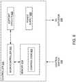
- FIG. 2depicts a schematic block diagram of one embodiment of a guidewire manipulation device 100.
- the guidewire manipulation device 100defines an axially longitudinal passage 204 through which the guidewire 102 is threaded during use.
- the guidewire manipulation device 100comprises a housing 200, an actuator 206, and a chuck 202.
- the chuck 202comprises a guidewire locking mechanism 208. During use, the chuck 202 is locked to the guidewire 102 using the locking mechanism 208. Once locked, the actuator selectively imparts motive force (rotational motion and/or axial motion) to the guidewire102.
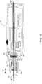
- Figure 3depicts a vertical cross-sectional view of one embodiment of a guidewire manipulation device 100.
- the actuator 206 of Figure 2is divided into a rotary actuator 206A and an axial actuator 206B such that the device may selectively apply to the guidewire: no motive force, rotary motive force or rotary and axial motive force.
- Device 100comprises a housing 200 typically formed into halves that are glued, screwed, or otherwise affixed to each other to form an enclosure.
- a housing 200typically formed into halves that are glued, screwed, or otherwise affixed to each other to form an enclosure.
- the housing 200Within the housing 200 are defined slots 350 wherein are retained bushings 302A and 302B.
- the bushings 302A and 302Bsupport an axle 300.
- the axle 300defines the passage 204 extending axially through the axle 300. When in use, the guidewire 102 is threaded through the passage 204.
- the rotary actuator 206Acomprises the axle 300, a motor 328, a drive assembly 326, a controller 330, and a control switch 332.
- the drive assembly 326couples rotational motion of the motor 328 to the axle 300 using a plurality of gears, further described with respect to Figure 4 below.
- the controller 330is simply one or more batteries that are coupled to the motor 328 via the control switch 332.
- the control switch 332may simply apply a voltage from the one or more batteries to the motor 328 to cause the motor 328 to rotate.
- the control switch 332is a simple single-pole, single-throw (SPST), momentary contact switch.
- the controller 330comprises a programmable microcontroller as described with respect to Figure 6 below.
- the switch 332may apply voltage to cause the motor 328 to selectively rotate clockwise or counterclockwise.
- the control switch 332is generally mounted to be exposed to the exterior of the housing 200 and facilitate manipulation by one hand of a user (e.g., a thumb activated push-button or slide switch.
- the axle 300is coupled to a chuck 202.
- the chuck 202comprises a coupler 304, a hub 324 and a wedge 314.
- the coupler 304 and the axle 300have splined mating surfaces 342 for coupling the rotational motion of the axle 300 to the chuck 202, while allowing the coupler 304 to move in an axial direction.
- the hub 324is threaded onto the coupler 304 at surface 312.
- the wedge 314is located in a window 352 defined by the coupler 304.
- the hub 324retains the wedge 314 within the window 352.
- the hub 324In a disengaged (unlocked) position, the hub 324 does not impart pressure to the wedge 314 thereby allowing the guidewire 102 to slide freely beneath the wedge 314 and through the passage 204.
- the hub 324To lock the guidewire into the lock mechanism 208, the hub 324 is rotated relative to the coupler 304 such that the angled surface 316 of the hub 324 interacts with the top surface 318 of the wedge 314.
- the wedge 314is forced against the guidewire 102. Consequently, the guidewire is captured between the wedge 314 and the coupler 304 and thereby locked into the chuck 202. Once locked, any motion of the chuck 202 is imparted as motive force to the guidewire 102.
- the coupler 304comprises a spring seat 354 supporting a first end of a spring 306.
- the second end of spring 306rests against a flange 322 that extends from the inner surface of the housing 200.
- the spring 306is one embodiment of a resilient member that biases the coupler 304 inwardly toward the axle 300.
- the coupler 304further comprises a flange 320 that extends radially from the outer surface of the coupler 304.
- the flange 320is positioned along the coupler 304 to limit the amount of axial movement that can be imparted to the chuck 202.
- the flange 320abuts the housing flange 322. As such, the spring 306 biases the coupler 304 to maintain contact between the flange 320 and the flange 322.
- the bottom surface 356 of the hub 324is dimpled.
- the surface 356interacts with a protrusion 336 extending from the exterior surface of the housing 200 proximate the surface 356 of the hub 324.
- the spring 306insurers that the protrusion 336 interacts with the dimpled surface 356.
- the hub 324is rotated relative to the coupler 304 along the threads 312 to decouple the protrusion 336 from the surface 356.
- the locking mechanism 208retains the guidewire 102 such that rotational motion of the axle 300 is imparted to the guidewire 102 without imparting axial motion.
- the axial motion actuator 206Bcomprises the hub 324, spring 306, coupler 304 and the housing 200.
- FIG 4depicts a cross sectional view of the drive assembly 326 of the rotary actuator 206A taken along line 4-4 of Figure 3 in accordance with one embodiment of the invention.
- the drive assembly 326comprises a motor gear 400, an intermediary gear 402 and an axle gear 404.
- the motor 328 of Figure 3is coupled to the motor gear 400 to impart rotational motion to the motor gear.
- the axle gear 404is formed as an integral part of this surface of the axle 300 of Figure 3 .
- the intermediary gear 402is designed to provide a gear ratio between the motor gear 400 and axle gear 404.
- the diameters and the number of teeth of each gearis considered to be a design choice that will do fine the speed of rotational motion of the guidewire as well as the oscillatory speed of the axial motion.
- the motor 328 of Figure 3may be coupled to the axle via other forms of drive assemblies, e.g., direct drive, worm gear, and/or the like.
- the specific motor and drive assembly characteristicsare considered a design choice to develop specific guidewire rotation speed and torque.
- the drive assemblymay be adjustable to facilitate creating specific speed and torque profiles or adjustments. One form of adjustments may be facilitated by the use of a stepper motor that can be controlled with a pulse width modulated signal produced by the controller, as discussed below.
- An alternative embodiment for imparting rotatary motive force in selectable directionsuses a gear train comprising two larger diameter spur gears mounted on a common shaft that is driven constantly in one direction by an electric motor.
- Each of the two spur gearshas a section of its teeth, something over 1 ⁇ 2 its total number, removed.
- the removed sections of teethare positioned such that only one or the other of two additional smaller spur gears, each located to be driven by one of these common shaft gears, will be driven at a time.
- the two smaller spur gearsare then used one at a time to drive the gear on the axle, but the positioning of one additional gear between just one of these driving gears and the axle gear results in the rotational direction of the axle being reversed when that set is driving the axle gear.
- Another embodimentif only forward and reversing is required without a near constant rotational speed in either direction, has the spur gear on the axle driven by a pivoted 1/4 pie shaped plate.
- the toothed curved section opposite the pivot near the tipwould have the correct pitch radius to mesh with the axle spur gear.
- This pivoted gear section platewould have, running upwards from its pivot, a slot in its face in which a pin, mounted off-center on a disc, could slide up and down freely. As an electric motor turns this disc in a constant direction, it would cause the pivoted plate to wobble back and forth so that its gear section drives the axle spur gear in one direction and then in the reverse direction.
- FIG. 5depicts a perspective view of the hub 324 in accordance with one embodiment of the invention.
- the hub 324comprises a surface 356 having a plurality of dimples 504 and spaces 502 between the dimples 504.
- the hub 324further comprises a threaded interior surface 312.
- the threaded interior surface 312is adapted to interact with a threaded exterior surface of the couple or 304 to adjust the position of the hub relative to the coupler 304 and the wedge 314.
- the dimples 504 and the spaces between the dimples 502are adapted to interact with the protrusion 336 to impart axial motion to the chuck 202.
- the spacing of the dimples and the speed of the motorcontrol the oscillation rate of the axial motion.
- the depth of the dimples 504 relative to the spaces 504 on the surface 356controls the travel distance of the axial motion.
- FIG. 6depicts a block diagram of the controller 330 used in accordance with one embodiment of the present invention.
- the controller 330comprises a microcontroller 600, support circuits 602, memory 604 and a power supply 606.
- the microcontroller 600may be one or more of many commercially available microcontrollers, microprocessors, application specific integrated circuits (ASIC), and the like.
- the support circuits 602comprise well known circuits that facilitate the operation of the microcontroller 600 including, but not limited to, clock circuits, cache, power supplies, input/output circuits, indicators, sensors, and/or the like.
- the power supply 606comprises one or more batteries.
- the power supply 606may comprise in AC to DC converter to allow the guidewire manipulation device to be plugged into a wall socket.
- the power supply 606may comprise one or more batteries and a charging circuit for the batteries may be inductively coupled to a base charger.
- the memory 604may be any form of memory device used to store digital instructions for the microcontroller 600 as well as data.
- the memory 604is random access memory or read only memory comprising control code 608 (e.g., computer readable instructions) that are used to control the actuator 206 to impart motion to the guidewire.
- control code 608e.g., computer readable instructions
- the programs utilized by the microcontroller 600 to control the actuator 206are generally controlled by the control switch 332 and/or another input device.
- the motor 328is a stepper motor that is controlled using, for example, a pulse width modulated signal produced by the controller 332 to impart specific torque and/or speed profiles to the motor 328.
- predefined programscan be generated and selected through manipulation of the switch 332 to enable a user to overcome specific types of obstructions within the path of the guidewire. For example, if a surgeon encounters a specific type of embolism, a specific program defining the motion of the guidewire to overcome the obstruction can be selected and implemented.
- Various programscan be generated through empirical study of guidewire utilization in endovascular procedures. To select a particular motion pattern, the switch may be a slide switch having a plurality of selectable positions, where each position corresponds to a different motion pattern.
- Figure 7depicts a vertical cross-sectional view of a guidewire manipulation device 650 according to an alternative embodiment of the invention.
- the use of axial motionis selected through manipulation of a mechanical switch 702.
- this embodimentselectively imparts to a guidewire: no motive force, rotary motive force, or rotary and axial motive force.
- the device 650comprises a rotational actuator 206A as described above with respect to Figure 3 .
- a coupler 700comprises a spring seat 750, a dimpled flange 710 and a switch stop 752.
- a slidable switch 702comprises an extension 704 that interacts with a switch seat 752. They switch seat 752 and the spring seat 754 define a space 706 that captures the switch extension 704.
- Manipulation of the switch 702causes the coupler 700 to move axially along the surface that mates with the axle 300.
- a spring 708is positioned between the spring seat 705 and the housing flange 322. The spring 708 biases the coupler inwardly toward the axle 300.
- the dimpled flange 702radially extends from the coupler 700. One surface of the dimpled flange abuts the housing flange 322 to limit the distance the coupler 700 moves in an axial direction.
- the dimpled flange 710has a surface aligned with a dimpled surface 712 of the housing 200.
- Figure 8depicts a partial perspective view of the coupler 700 in accordance with one embodiment of the invention.
- the coupler 700has an aperture 806 through which the guidewire is threaded.
- the dimpled flange 710comprises a radially extending flange 802 having a plurality of dimples 800 formed in the surface.
- the dimplesare formed as a sequence of wedges.
- the surface of the flange 802needs to be varied such that interaction with a corresponding surface causes axial movement of the coupler 700.
- Figure 9depicts a cross-sectional view of the housing 200 taken along line 9-9 in figure 7 .
- the surface 712comprises corresponding protrusions shaped to interact with the dimples in surface 800 of the coupler 700.
- the surface 712may comprise complementary wedges 900 to the surface 800 of the coupler 700. The shape of the wedges defines, in part, the distance travelled, the rate of acceleration of the guidewire, and the speed of the guidewire oscillation.
- Figure 10depicts an embodiment of the guidewire manipulation device 650 of Figure 7 where the dimpled flange 710 has been engaged the protrusion surface 712.
- the switch 702has moved the coupler 700 forward to facilitate engagement of the surfaces 710 and 712.
- the guidewire 102rotates as shown in arrow 1002 and axially oscillates as represented by arrow 1000.
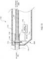
- Figure 11depicts a vertical cross-sectional view of a portion of a guidewire manipulation device 1100.
- Device 1100comprises an axial actuator 206B that can be selectively utilized without imparting rotational motion of the guidewire.
- the device 110selectively imparts to the guide wire: no motive force, rotary motive force, axial motive force, or axial and rotary motive force.
- the device 1100comprises a linear actuator 1116 couple to a shaft of 1114 that interacts with a fulcrum 1112.
- the linear actuator 1116imparts linear motion to one portion of the fulcrum 1112.
- the fulcrumis mounted upon a pivot point 1120 such that the fulcrum 1112 rotates about the pivot point 1120 as a linear motive force is applied to the fulcrum 1112.
- a second end of the fulcrum 1112interacts with a coupler 1104.
- the coupler 110as with prior embodiments, has a splined surface that interacts with the axle 300 to impart rotational motion to the coupler, as needed.
- the coupler 1104comprises a spring seat 1108.
- a spring 1106is positioned between the housing 1102 and the spring seat 1108 to bias the coupler 1104 toward the axle 300.
- the fulcrum 1102couples to the spring seat 1108 such that motion of the fulcrum 1102 axially moves the coupler 1104. In this manner, without any rotational motion the linear actuator 1116 imparts axial motion to the coupler and to guidewire 102 locked in the chuck 202.
- the linear actuator 1116may be a solenoid, piezoelectric actuator, linear motor, rotary motor and ball screw or rack/pinion, and/or the like.
- a hammer-drill type assemblymay be used to impart axial force to the guidewire.
- the controller 330in a manner similar to that described for controlling the motor 328 of Figure 3 may control the linear actuator 1116.
Landscapes
- Health & Medical Sciences (AREA)
- Life Sciences & Earth Sciences (AREA)
- Animal Behavior & Ethology (AREA)
- Veterinary Medicine (AREA)
- Public Health (AREA)
- Engineering & Computer Science (AREA)
- Biomedical Technology (AREA)
- Heart & Thoracic Surgery (AREA)
- General Health & Medical Sciences (AREA)
- Anesthesiology (AREA)
- Hematology (AREA)
- Pulmonology (AREA)
- Biophysics (AREA)
- Surgery (AREA)
- Vascular Medicine (AREA)
- Nuclear Medicine, Radiotherapy & Molecular Imaging (AREA)
- Medical Informatics (AREA)
- Molecular Biology (AREA)
- Surgical Instruments (AREA)
- Media Introduction/Drainage Providing Device (AREA)
Description
- Embodiments of the present invention generally relate to surgical guidewire utilization in surgical procedures and, more particularly, to an apparatus for manipulating a surgical guidewire.
- A surgical guidewire (referred to herein also as a guidewire) is typically a semi-rigid probe used as an initial access point for performing in endovascular surgical procedure. The guidewire is twisted, bent, and otherwise maneuvered through an access vessel in order to position the guidewire tip and a location a surgeon desires to treat. For example, document
US 2008/097465 refers to a guidewire manipulation device for manipulating a guidewire during a procedure. Preferably, the guidewire manipulation device includes a powered motor that drives a tandem roller assembly. The guidewire is passed through a hole positioned lengthwise through the device where the roller assembly engages the guidewire's outer surface. A user operates the manipulation device to rotate or vibrate (e.g., by rotating between a clockwise and counter clockwise direction quickly) the guidewire as appropriate. DocumentUS 2007/016105 describes a wire torque apparatus and methods for engaging a wire torque apparatus. Wire insertion devices and methods for inserting a wire into a catheter are disclosed. An improved aneurysm clip utilizes non-metallic material. An improvement to an aneurysm clip applicator tool includes a power supply to power an electromagnet, an adjustable counter element that is attracted to the electromagnet when the electromagnet is magnetized, and a switch to disengage the electromagnet. When the electromagnet is magnetized and comes within a certain proximity to the counter element, the electromagnet and the counter element attract and cling to one another. With a cam gripping wire against a surface, the practitioner can manipulate wire by manipulating apparatus. DocumentUS 5,392,778 describes a torque device capable of both securement to a guidewire and release with only one hand, is constructed of a pair of tubular elements, one terminating in a series of prongs with outer surfaces which form an outwardly expanding cone, and the other surrounding the prongs and containing an internal, inwardly extending flange which engages the outer surfaces of the prongs. DocumentUS 6,752,800 describes a catheter handle for controlling the advancement of a guide wire through a catheter is described. The catheter handle has a distal end to which is coupled a luer lock element, and a proximal end to which a control knob is coupled. The luer lock element is adaptable to allow coupling of the catheter handle to any commonly available commercial catheter. The control knob is coupled to a guide wire advancement mechanism. Movement of the control knob is translated by the advancement mechanism to advancement or braking of the guide wire. - Conventional guidewire manipulation methods often involve applying torque to the guidewire to aid its passage through tortuous and clogged vessels. Typically, spinning the guidewire in one's fingertips creates torque to assist in manipulating the guidewire through an obstructed and/or difficult passageway. This technique is also known as "helicoptering", alluding to the spinning blades of a helicopter.
- However, applying torque is difficult since surgical guidewires have an extremely small diameter and typically have a low friction surface to promote passage through a vessel. Additionally, the gloves of a surgeon or often coated with blood or saline solution, further increasing the slickness of a guidewire. In this respect, helicoptering and similar maneuvers can be time-consuming and inefficient. This inefficiency not only frustrates surgeons, but also increases procedure completion time and, therefore, increases procedure costs.
- Furthermore, in instances where an obstruction is encountered within a vessel, a surgeon generally applies axial motion in an oscillatory manner to drive the guidewire through or past the obstruction. During surgery, an endovascular surgeon may encounter an occlusion that is chronic and/or calcified. Such occlusions have a hard shell with a consistency much like plaster. These forms of obstructions can be difficult and sometimes impossible to penetrate using manual manipulation of a guidewire. Consequently, a procedure may be abandoned when such difficult obstructions are encountered.
- Therefore, there is a need in the art for a method and apparatus for manipulating a guidewire.
- Embodiments of the present invention comprise an apparatus for manipulating a surgical guidewire as defined in independent claim 1 and subsequent dependent claims 2-13.
- So that the manner in which the above recited features of the present invention can be understood in detail, a more particular description of the invention, briefly summarized above, may be had by reference to embodiments, some of which are illustrated in the appended drawings. It is to be noted, however, that the appended drawings illustrate only typical embodiments of this invention and are therefore not to be considered limiting of its scope, for the invention may admit to other equally effective embodiments.
Figure 1 illustrates a view of one embodiment of a guidewire manipulation device being used on a patient according to an embodiment of the present invention;Figure 2 depicts a schematic block diagram of a guidewire manipulation device according to an embodiment of the present invention;Figure 3 depicts a vertical cross-sectional view of a guidewire manipulation device according to an embodiment of the present invention;Figure 4 depicts a portion of an actuator used in the guidewire manipulation device ofFigure 3 ;Figure 5 depicts a perspective view of a hub of a chuck that imparts axial motive force to a guidewire when using the guidewire manipulation divisiveFigure 3 ;Figure 6 depicts a block diagram of a controller used in accordance with an embodiment of the present invention;Figure 7 depicts a vertical cross-sectional view of alternative embodiment of the guidewire manipulation device;Figure 8 depicts a partial perspective view of a portion of a guidewire drive assembly for the guidewire manipulation device ofFigure 7 ;Figure 9 depicts a cross-sectional view of a portion of the housing for the guidewire manipulation device ofFigure 7 ;Figure 10 depicts a vertical cross-sectional view of the guidewire manipulation device ofFigure 7 having the actuator engaged to apply axial motive force to the guidewire in accordance with one embodiment of the invention; andFigure 11 depicts a partial, vertical cross-sectional view of another embodiment of a guidewire manipulation device for imparting axial motive force to a guidewire.- Embodiments of the present invention comprise an apparatus for manipulating a surgical guidewire. The apparatus is embodied in a guidewire manipulation device for selectively imparting motive force (rotational and/or axial (linear) motion) to a surgical guidewire. In use, such a guidewire manipulation device is selectively locked to a surgical guidewire and is activated to impart motive force to maneuver the guidewire to a desired location during an endovascular procedure. The motive force applied to the guidewire is selectively rotational and/or axial to facilitate moving the surgical guidewire through a vessel and/or penetrating occlusions.
Figure 1 illustrates a view of aguidewire manipulation device 100 being used on apatient 110 according to one embodiment of the present invention. In one embodiment, theguidewire manipulation device 100 is a handheld device capable of fitting in the palm of a user's hand and being operated using one hand. In one embodiment, theguidewire manipulation device 100 is advanced over asurgical guidewire 102, i.e., theguidewire 102 passes through a longitudinally oriented passage in the device 100). During an endovascular procedure, theguidewire 102 is introduced into a vessel 106 (e.g., a femoral artery) of thepatient 110. Theguidewire manipulation device 100 is selectively locked to theguidewire 102. As the guidewire is advanced into the patient, the user operates themanipulation device 100 to impart motive force (rotational and/or axial motion) to theguidewire 102, as appropriate.- For example, as a
distal end 108 of theguidewire 102 reaches an angled or curved region of thevessel 106, the user locks themanipulation device 100 to the guidewire and imparts rotational motive force to the guidewire 102 (e.g., in a counterclockwise direction indicated by arrow 104), thereby causing thedistal end 108 of theguidewire 102 to more easily advance through the angled or curved region of thevessel 106. Once advanced past the region, thedevice 100 is unlocked from the guidewire and the guidewire can be further advanced through the vessel. In another example, thedistal end 108 of theguidewire 102 reaches an obstruction (e.g., an embolism) but is unable to pass the obstruction. The user then locks theguidewire manipulation device 100 to theguidewire 102 and imparts a vibratory motion (e.g., rapidly oscillating between clockwise and counterclockwise rotation). Such motion causes the distal end of theguidewire 102 to pass through the obstruction. In another example, when the distal end of theguidewire 102 reaches an obstruction, the user locks theguidewire manipulation device 102 to theguidewire 102 and imparts an axial motion (e.g., a linear movement of the guidewire 102) to create a jackhammer effect. In the embodiment, the user may lock thedevice 100 to theguidewire 102 and simultaneously impart both rotational and axial motion to theguidewire 102. In another embodiment of the invention, a sequence of predefined guidewire manipulations (i.e., a pattern) may be produced using a computer program for controlling the motion as described in detail below. Various motive patterns to be selectively used in various surgical situations can be selected from memory and applied to the guidewire. Figure 2 depicts a schematic block diagram of one embodiment of aguidewire manipulation device 100. Theguidewire manipulation device 100 defines an axiallylongitudinal passage 204 through which theguidewire 102 is threaded during use. Theguidewire manipulation device 100 comprises ahousing 200, anactuator 206, and achuck 202. Thechuck 202 comprises aguidewire locking mechanism 208. During use, thechuck 202 is locked to theguidewire 102 using thelocking mechanism 208. Once locked, the actuator selectively imparts motive force (rotational motion and/or axial motion) to the guidewire102.Figure 3 depicts a vertical cross-sectional view of one embodiment of aguidewire manipulation device 100. In this embodiment, theactuator 206 ofFigure 2 is divided into arotary actuator 206A and anaxial actuator 206B such that the device may selectively apply to the guidewire: no motive force, rotary motive force or rotary and axial motive force.Device 100 comprises ahousing 200 typically formed into halves that are glued, screwed, or otherwise affixed to each other to form an enclosure. Within thehousing 200 are definedslots 350 wherein are retainedbushings bushings axle 300. Theaxle 300 defines thepassage 204 extending axially through theaxle 300. When in use, theguidewire 102 is threaded through thepassage 204.- The
rotary actuator 206A comprises theaxle 300, amotor 328, adrive assembly 326, acontroller 330, and acontrol switch 332. Thedrive assembly 326 couples rotational motion of themotor 328 to theaxle 300 using a plurality of gears, further described with respect toFigure 4 below. In one embodiment of the invention, thecontroller 330 is simply one or more batteries that are coupled to themotor 328 via thecontrol switch 332. In such an embodiment, thecontrol switch 332 may simply apply a voltage from the one or more batteries to themotor 328 to cause themotor 328 to rotate. In its simplest form, thecontrol switch 332 is a simple single-pole, single-throw (SPST), momentary contact switch. In more complex embodiments, thecontroller 330 comprises a programmable microcontroller as described with respect toFigure 6 below. In other embodiments, theswitch 332 may apply voltage to cause themotor 328 to selectively rotate clockwise or counterclockwise. Thecontrol switch 332 is generally mounted to be exposed to the exterior of thehousing 200 and facilitate manipulation by one hand of a user (e.g., a thumb activated push-button or slide switch. - The
axle 300 is coupled to achuck 202. In one embodiment, thechuck 202 comprises acoupler 304, ahub 324 and awedge 314. Thecoupler 304 and theaxle 300 have splined mating surfaces 342 for coupling the rotational motion of theaxle 300 to thechuck 202, while allowing thecoupler 304 to move in an axial direction. Thehub 324 is threaded onto thecoupler 304 atsurface 312. Thewedge 314 is located in awindow 352 defined by thecoupler 304. Thehub 324 retains thewedge 314 within thewindow 352. In a disengaged (unlocked) position, thehub 324 does not impart pressure to thewedge 314 thereby allowing theguidewire 102 to slide freely beneath thewedge 314 and through thepassage 204. To lock the guidewire into thelock mechanism 208, thehub 324 is rotated relative to thecoupler 304 such that theangled surface 316 of thehub 324 interacts with the top surface 318 of thewedge 314. As thehub 324 is moved relative to thecoupler 304 via the mating threadedsurfaces 312, thewedge 314 is forced against theguidewire 102. Consequently, the guidewire is captured between thewedge 314 and thecoupler 304 and thereby locked into thechuck 202. Once locked, any motion of thechuck 202 is imparted as motive force to theguidewire 102. - Other embodiments of the invention utilize other forms of chucks. In a broad sense, any mechanism that can be used to selectively lock the guidewire to a source of motive force may be used. Other forms of chucks having multiple jaws or compressive slotted cylinders are applicable.
- The
coupler 304 comprises aspring seat 354 supporting a first end of aspring 306. The second end ofspring 306 rests against aflange 322 that extends from the inner surface of thehousing 200. Thespring 306 is one embodiment of a resilient member that biases thecoupler 304 inwardly toward theaxle 300. Thecoupler 304 further comprises aflange 320 that extends radially from the outer surface of thecoupler 304. Theflange 320 is positioned along thecoupler 304 to limit the amount of axial movement that can be imparted to thechuck 202. Theflange 320 abuts thehousing flange 322. As such, thespring 306 biases thecoupler 304 to maintain contact between theflange 320 and theflange 322. - To impart axial motion to the
chuck 202, thebottom surface 356 of thehub 324 is dimpled. Thesurface 356 interacts with aprotrusion 336 extending from the exterior surface of thehousing 200 proximate thesurface 356 of thehub 324. Depending on the position of thehub 324 relative to thecoupler 304, thespring 306 insurers that theprotrusion 336 interacts with thedimpled surface 356. Upon locking thechuck 202 to theguidewire 102 and imparting rotation to thechuck 202, theguidewire 102 moves in an axial direction as indicated byarrow 358. To disengage the axial motive force, thehub 324 is rotated relative to thecoupler 304 along thethreads 312 to decouple theprotrusion 336 from thesurface 356. In this manner, thelocking mechanism 208 retains theguidewire 102 such that rotational motion of theaxle 300 is imparted to theguidewire 102 without imparting axial motion. In this embodiment, theaxial motion actuator 206B comprises thehub 324,spring 306,coupler 304 and thehousing 200. Figure 4 depicts a cross sectional view of thedrive assembly 326 of therotary actuator 206A taken along line 4-4 ofFigure 3 in accordance with one embodiment of the invention. Thedrive assembly 326 comprises amotor gear 400, anintermediary gear 402 and anaxle gear 404. Themotor 328 ofFigure 3 is coupled to themotor gear 400 to impart rotational motion to the motor gear. In one embodiment, theaxle gear 404 is formed as an integral part of this surface of theaxle 300 ofFigure 3 . Theintermediary gear 402 is designed to provide a gear ratio between themotor gear 400 andaxle gear 404. The diameters and the number of teeth of each gear is considered to be a design choice that will do fine the speed of rotational motion of the guidewire as well as the oscillatory speed of the axial motion.- In other embodiments, the
motor 328 ofFigure 3 may be coupled to the axle via other forms of drive assemblies, e.g., direct drive, worm gear, and/or the like. The specific motor and drive assembly characteristics are considered a design choice to develop specific guidewire rotation speed and torque. In some embodiments, the drive assembly may be adjustable to facilitate creating specific speed and torque profiles or adjustments. One form of adjustments may be facilitated by the use of a stepper motor that can be controlled with a pulse width modulated signal produced by the controller, as discussed below. - An alternative embodiment for imparting rotatary motive force in selectable directions uses a gear train comprising two larger diameter spur gears mounted on a common shaft that is driven constantly in one direction by an electric motor. Each of the two spur gears has a section of its teeth, something over ½ its total number, removed. The removed sections of teeth are positioned such that only one or the other of two additional smaller spur gears, each located to be driven by one of these common shaft gears, will be driven at a time. The two smaller spur gears are then used one at a time to drive the gear on the axle, but the positioning of one additional gear between just one of these driving gears and the axle gear results in the rotational direction of the axle being reversed when that set is driving the axle gear.
- Another embodiment, if only forward and reversing is required without a near constant rotational speed in either direction, has the spur gear on the axle driven by a pivoted 1/4 pie shaped plate. The toothed curved section opposite the pivot near the tip would have the correct pitch radius to mesh with the axle spur gear. This pivoted gear section plate would have, running upwards from its pivot, a slot in its face in which a pin, mounted off-center on a disc, could slide up and down freely. As an electric motor turns this disc in a constant direction, it would cause the pivoted plate to wobble back and forth so that its gear section drives the axle spur gear in one direction and then in the reverse direction.
Figure 5 depicts a perspective view of thehub 324 in accordance with one embodiment of the invention. Thehub 324 comprises asurface 356 having a plurality ofdimples 504 andspaces 502 between thedimples 504. Thehub 324 further comprises a threadedinterior surface 312. The threadedinterior surface 312 is adapted to interact with a threaded exterior surface of the couple or 304 to adjust the position of the hub relative to thecoupler 304 and thewedge 314. Thedimples 504 and the spaces between thedimples 502 are adapted to interact with theprotrusion 336 to impart axial motion to thechuck 202. The spacing of the dimples and the speed of the motor control the oscillation rate of the axial motion. Furthermore, the depth of thedimples 504 relative to thespaces 504 on thesurface 356 controls the travel distance of the axial motion.Figure 6 depicts a block diagram of thecontroller 330 used in accordance with one embodiment of the present invention. Thecontroller 330 comprises amicrocontroller 600,support circuits 602,memory 604 and apower supply 606. Themicrocontroller 600 may be one or more of many commercially available microcontrollers, microprocessors, application specific integrated circuits (ASIC), and the like. Thesupport circuits 602 comprise well known circuits that facilitate the operation of themicrocontroller 600 including, but not limited to, clock circuits, cache, power supplies, input/output circuits, indicators, sensors, and/or the like. In one embodiment, thepower supply 606 comprises one or more batteries. In other embodiments, thepower supply 606 may comprise in AC to DC converter to allow the guidewire manipulation device to be plugged into a wall socket. In further embodiments, thepower supply 606 may comprise one or more batteries and a charging circuit for the batteries may be inductively coupled to a base charger.- The
memory 604 may be any form of memory device used to store digital instructions for themicrocontroller 600 as well as data. In one embodiment, thememory 604 is random access memory or read only memory comprising control code 608 (e.g., computer readable instructions) that are used to control theactuator 206 to impart motion to the guidewire. The programs utilized by themicrocontroller 600 to control theactuator 206 are generally controlled by thecontrol switch 332 and/or another input device. - In one example not forming part of the invention, the
motor 328 is a stepper motor that is controlled using, for example, a pulse width modulated signal produced by thecontroller 332 to impart specific torque and/or speed profiles to themotor 328. In some examples, predefined programs can be generated and selected through manipulation of theswitch 332 to enable a user to overcome specific types of obstructions within the path of the guidewire. For example, if a surgeon encounters a specific type of embolism, a specific program defining the motion of the guidewire to overcome the obstruction can be selected and implemented. Various programs can be generated through empirical study of guidewire utilization in endovascular procedures. To select a particular motion pattern, the switch may be a slide switch having a plurality of selectable positions, where each position corresponds to a different motion pattern. Figure 7 depicts a vertical cross-sectional view of aguidewire manipulation device 650 according to an alternative embodiment of the invention. In this embodiment, the use of axial motion is selected through manipulation of amechanical switch 702. As with the prior embodiment, this embodiment selectively imparts to a guidewire: no motive force, rotary motive force, or rotary and axial motive force. Thedevice 650 comprises arotational actuator 206A as described above with respect toFigure 3 . In this embodiment, acoupler 700 comprises aspring seat 750, adimpled flange 710 and aswitch stop 752. Aslidable switch 702 comprises anextension 704 that interacts with aswitch seat 752. They switchseat 752 and the spring seat 754 define aspace 706 that captures theswitch extension 704. Manipulation of theswitch 702 causes thecoupler 700 to move axially along the surface that mates with theaxle 300. Aspring 708 is positioned between the spring seat 705 and thehousing flange 322. Thespring 708 biases the coupler inwardly toward theaxle 300. Thedimpled flange 702 radially extends from thecoupler 700. One surface of the dimpled flange abuts thehousing flange 322 to limit the distance thecoupler 700 moves in an axial direction. Thedimpled flange 710 has a surface aligned with adimpled surface 712 of thehousing 200. When the guidewire is locked to thechuck 202 and therotational actuator 206A is activated, theguidewire 102 rotates without any axial movement. As described further with respect toFigure 10 below, when theswitch 702 is moved forward to cause the dimpled surface offlange 710 to engage thedimpled surface 712, theguidewire 102 axial motive force is imparted to theguidewire 102.Figure 8 depicts a partial perspective view of thecoupler 700 in accordance with one embodiment of the invention. Thecoupler 700 has anaperture 806 through which the guidewire is threaded. Thedimpled flange 710 comprises aradially extending flange 802 having a plurality ofdimples 800 formed in the surface. In one embodiment, the dimples are formed as a sequence of wedges. In other embodiments, to cause axial motion of the chuck when thecoupler 700 is rotated, the surface of theflange 802 needs to be varied such that interaction with a corresponding surface causes axial movement of thecoupler 700.Figure 9 depicts a cross-sectional view of thehousing 200 taken along line 9-9 infigure 7 . In one embodiment, thesurface 712 comprises corresponding protrusions shaped to interact with the dimples insurface 800 of thecoupler 700. In another embodiment, thesurface 712 may comprisecomplementary wedges 900 to thesurface 800 of thecoupler 700. The shape of the wedges defines, in part, the distance travelled, the rate of acceleration of the guidewire, and the speed of the guidewire oscillation.Figure 10 depicts an embodiment of theguidewire manipulation device 650 ofFigure 7 where thedimpled flange 710 has been engaged theprotrusion surface 712. In this manner, theswitch 702 has moved thecoupler 700 forward to facilitate engagement of thesurfaces chuck 202 locks to theguidewire 102 and the rotary actuator is activated, theguidewire 102 rotates as shown inarrow 1002 and axially oscillates as represented byarrow 1000.Figure 11 depicts a vertical cross-sectional view of a portion of aguidewire manipulation device 1100.Device 1100 comprises anaxial actuator 206B that can be selectively utilized without imparting rotational motion of the guidewire. As such, with this embodiment, thedevice 110 selectively imparts to the guide wire: no motive force, rotary motive force, axial motive force, or axial and rotary motive force.- In one embodiment, the
device 1100 comprises alinear actuator 1116 couple to a shaft of 1114 that interacts with a fulcrum 1112. Thelinear actuator 1116 imparts linear motion to one portion of the fulcrum 1112. The fulcrum is mounted upon apivot point 1120 such that the fulcrum 1112 rotates about thepivot point 1120 as a linear motive force is applied to the fulcrum 1112. A second end of the fulcrum 1112 interacts with acoupler 1104. Thecoupler 1104, as with prior embodiments, has a splined surface that interacts with theaxle 300 to impart rotational motion to the coupler, as needed. Thecoupler 1104 comprises aspring seat 1108. A spring 1106 is positioned between thehousing 1102 and thespring seat 1108 to bias thecoupler 1104 toward theaxle 300. Thefulcrum 1102 couples to thespring seat 1108 such that motion of thefulcrum 1102 axially moves thecoupler 1104. In this manner, without any rotational motion thelinear actuator 1116 imparts axial motion to the coupler and to guidewire 102 locked in thechuck 202. - In one example, the
linear actuator 1116 may be a solenoid, piezoelectric actuator, linear motor, rotary motor and ball screw or rack/pinion, and/or the like. In another embodiment, a hammer-drill type assembly may be used to impart axial force to the guidewire. - The
controller 330 in a manner similar to that described for controlling themotor 328 ofFigure 3 may control thelinear actuator 1116.
Claims (13)
- Apparatus for manipulating a guidewire during an endovascular procedure, comprising:a chuck for selectively coupling motive force to a guidewire;an actuator, coupled to the chuck, for imparting an axial motive force to the chuck and a rotary motive force to the chuck, anda housing, supporting the chuck and the actuator, sized to fit in a palm of a user, wherein the actuator is configured to impart simultaneous rotational and axial motion to the guidewire via the chuck.
- The apparatus of claim 1, wherein the chuck comprises a locking mechanism for selectively locking the chuck to the guidewire.
- The apparatus of any of claims 1 to 2, wherein the chuck comprises:a coupler for receiving the motive force from the actuator;a hub coupled to the coupler; anda wedge positioned within a window in the coupler and retained in the window by the hub, the wedge having an angled surface that interacts with the hub to move the wedge between a guidewire locked position and a guidewire unlocked position.
- The apparatus of claim 3, wherein the hub comprises a dimpled surface for interacting with a protrusion, and wherein the actuator imparts rotary motive force to the hub, and the dimpled surface interacts with the protrusion to produce axial motive force.
- The apparatus of any of claims 3 to 4, wherein the coupler comprises a radially extending flange having a dimpled surface for interacting with a protrusion, where the actuator imparts rotary motive force to the coupler and the dimpled surface interacts with the protrusion to produce axial motive force.
- The apparatus of any of claims 1 to 5, wherein the actuator further comprises a linear actuator coupled to the chuck.
- The apparatus of any of claims 1 to 6, further comprising a controller, coupled to the actuator, for controlling activation of the actuator.
- The apparatus of any of claims 1 to 7, wherein the actuator comprises a plurality of gears to selectively impart rotary motive force in a counterclockwise direction and a clockwise direction.
- The apparatus of any of claims 1 to 8, further comprising:
an axle supported within the housing and coupled to a rotary actuator, the axle having a longitudinally oriented passage configured to thread the guidewire therethrough. - The apparatus of claim 7, wherein the controller is programmed with a plurality of motive force patterns.
- The apparatus of claim 9, wherein the actuator includes a motor and a drive assembly for coupling rotational motion of the motor to the axle.
- The apparatus of claim 11, further comprising a switch coupled to an exterior of the housing and coupled to the motor, the switch configured for manipulation by the user while the user holds the housing.
- The apparatus of claim 1, wherein the axial motion includes a linear oscillation comprising a jackhammer effect.
Applications Claiming Priority (2)
| Application Number | Priority Date | Filing Date | Title |
|---|---|---|---|
| US15138809P | 2009-02-10 | 2009-02-10 | |
| PCT/US2010/023629WO2010093630A2 (en) | 2009-02-10 | 2010-02-09 | Method and apparatus for manipulating a surgical guidewire |
Publications (3)
| Publication Number | Publication Date |
|---|---|
| EP2395924A2 EP2395924A2 (en) | 2011-12-21 |
| EP2395924A4 EP2395924A4 (en) | 2013-08-28 |
| EP2395924B1true EP2395924B1 (en) | 2021-03-24 |
Family
ID=42540994
Family Applications (1)
| Application Number | Title | Priority Date | Filing Date |
|---|---|---|---|
| EP10741626.5AActiveEP2395924B1 (en) | 2009-02-10 | 2010-02-09 | Apparatus for manipulating a surgical guidewire |
Country Status (4)
| Country | Link |
|---|---|
| US (7) | US8926529B2 (en) |
| EP (1) | EP2395924B1 (en) |
| JP (2) | JP5818357B2 (en) |
| WO (1) | WO2010093630A2 (en) |
Families Citing this family (56)
| Publication number | Priority date | Publication date | Assignee | Title |
|---|---|---|---|---|
| CN101547653B (en) | 2006-09-13 | 2012-02-29 | 瓦斯库勒英赛特有限公司 | Vascular Therapy Devices |
| EP3689274A1 (en) | 2007-02-05 | 2020-08-05 | Boston Scientific Limited | Thrombectomy system |
| US9510854B2 (en) | 2008-10-13 | 2016-12-06 | Boston Scientific Scimed, Inc. | Thrombectomy catheter with control box having pressure/vacuum valve for synchronous aspiration and fluid irrigation |
| EP2395924B1 (en)* | 2009-02-10 | 2021-03-24 | Vesatek, LLC | Apparatus for manipulating a surgical guidewire |
| US9962229B2 (en) | 2009-10-12 | 2018-05-08 | Corindus, Inc. | System and method for navigating a guide wire |
| US9585667B2 (en)* | 2010-11-15 | 2017-03-07 | Vascular Insights Llc | Sclerotherapy catheter with lumen having wire rotated by motor and simultaneous withdrawal from vein |
| US10118020B2 (en) | 2011-12-07 | 2018-11-06 | Traumatek Solutions B.V. | Devices and methods for endovascular access and therapy |
| US9439653B2 (en) | 2011-12-07 | 2016-09-13 | Traumatek Solutions B.V. | Devices and methods for endovascular access and therapy |
| US9402555B2 (en)* | 2011-12-29 | 2016-08-02 | St. Jude Medical, Atrial Fibrillation Division, Inc. | Drive assembly for use in a robotic control and guidance system |
| US20140066900A1 (en) | 2012-09-06 | 2014-03-06 | Corindus, Inc. | System for guide catheter control |
| US9532789B2 (en)* | 2012-11-14 | 2017-01-03 | British Columbia Cancer Agency Branch | Cannulated hammer drill attachment |
| US9566414B2 (en) | 2013-03-13 | 2017-02-14 | Hansen Medical, Inc. | Integrated catheter and guide wire controller |
| US9283046B2 (en) | 2013-03-15 | 2016-03-15 | Hansen Medical, Inc. | User interface for active drive apparatus with finite range of motion |
| US10849702B2 (en) | 2013-03-15 | 2020-12-01 | Auris Health, Inc. | User input devices for controlling manipulation of guidewires and catheters |
| US9375553B2 (en)* | 2013-04-25 | 2016-06-28 | Freddy Dwight CHRISMAN | Compression torque device |
| US9814864B2 (en)* | 2013-05-17 | 2017-11-14 | Covidien Lp | Torque apparatus for use with a guidewire |
| US11020016B2 (en) | 2013-05-30 | 2021-06-01 | Auris Health, Inc. | System and method for displaying anatomy and devices on a movable display |
| US20160175564A1 (en)* | 2013-08-05 | 2016-06-23 | Vascular Imaging Corporation | Guidewire torque handle |
| CA2922253A1 (en)* | 2013-09-12 | 2015-03-19 | Boston Scientific Scimed, Inc. | Medical device with a movable tip |
| US9782195B2 (en)* | 2013-11-20 | 2017-10-10 | Board Of Regents Of The University Of Nebraska | Fluid jet arterial surgical device |
| EP3243476B1 (en) | 2014-03-24 | 2019-11-06 | Auris Health, Inc. | Systems and devices for catheter driving instinctiveness |
| US10159819B2 (en)* | 2014-04-24 | 2018-12-25 | Medtronic Vascular Galway | Control module for delivery systems |
| US9883877B2 (en) | 2014-05-19 | 2018-02-06 | Walk Vascular, Llc | Systems and methods for removal of blood and thrombotic material |
| WO2016090270A1 (en) | 2014-12-05 | 2016-06-09 | Corindus, Inc. | System and method for navigating a guide wire |
| GB2536714B (en)* | 2015-03-27 | 2017-05-10 | Cook Medical Technologies Llc | Vessel ablation system with adjustable ablation terminal |
| FR3037249A1 (en)* | 2015-06-12 | 2016-12-16 | Robocath | ROBOTIC METHOD FOR CATHETER TRAINING AND CATHETER GUIDE |
| EP3313289B1 (en) | 2015-06-23 | 2021-03-17 | Traumatek Solutions B.V. | Vessel cannulation device |
| JP6885923B2 (en)* | 2015-08-12 | 2021-06-16 | ヴェサテック エルエルシー | Systems and methods for operating long medical devices |
| US10561440B2 (en)* | 2015-09-03 | 2020-02-18 | Vesatek, Llc | Systems and methods for manipulating medical devices |
| US10874830B2 (en) | 2015-10-05 | 2020-12-29 | Autonomix Medical, Inc. | Smart torquer and methods of using the same |
| US12295646B2 (en) | 2015-10-05 | 2025-05-13 | Autonomix Medical, Inc. | Smart torquer and methods of using the same |
| WO2017060439A1 (en)* | 2015-10-09 | 2017-04-13 | Koninklijke Philips N.V. | Advanced control features for steering devices for intravascular devices and associated systems and methods |
| US10226263B2 (en) | 2015-12-23 | 2019-03-12 | Incuvate, Llc | Aspiration monitoring system and method |
| WO2017151178A1 (en)* | 2016-03-04 | 2017-09-08 | California Institute Of Technology | Placid wire mechanism of penetrating blockings and occlusions in arteries |
| US11037464B2 (en) | 2016-07-21 | 2021-06-15 | Auris Health, Inc. | System with emulator movement tracking for controlling medical devices |
| US10478599B2 (en) | 2016-11-17 | 2019-11-19 | Vascugenix LLC | Compression torque device |
| JP7111374B2 (en)* | 2017-02-16 | 2022-08-02 | クリアフロー, インコーポレイテッド | spool drive system |
| EP3417901A1 (en) | 2017-06-20 | 2018-12-26 | Siemens Healthcare GmbH | Autonomous catheterization assembly |
| WO2019113391A1 (en) | 2017-12-08 | 2019-06-13 | Auris Health, Inc. | System and method for medical instrument navigation and targeting |
| US11712717B2 (en) | 2018-03-28 | 2023-08-01 | California Institute Of Technology | Dual frequency ultrasonic and sonic actuator with constrained impact mass |
| US11179213B2 (en) | 2018-05-18 | 2021-11-23 | Auris Health, Inc. | Controllers for robotically-enabled teleoperated systems |
| US11678905B2 (en) | 2018-07-19 | 2023-06-20 | Walk Vascular, Llc | Systems and methods for removal of blood and thrombotic material |
| CN117958987A (en) | 2018-09-19 | 2024-05-03 | 科林达斯公司 | Robot-assisted movement of elongate medical devices |
| US11672958B2 (en) | 2018-10-16 | 2023-06-13 | Olympus Corporation | Guidewire locking device |
| US11666206B2 (en)* | 2018-10-16 | 2023-06-06 | Olympus Corporation | Guidewire locking device |
| WO2020264418A1 (en) | 2019-06-28 | 2020-12-30 | Auris Health, Inc. | Console overlay and methods of using same |
| EP4125534B1 (en) | 2020-03-31 | 2025-02-26 | Bard Peripheral Vascular, Inc. | Vascular device insertion system and apparatus |
| US12274458B2 (en) | 2021-02-15 | 2025-04-15 | Walk Vascular, Llc | Systems and methods for removal of blood and thrombotic material |
| JP2024506374A (en) | 2021-02-15 | 2024-02-13 | ウォーク バスキュラー, エルエルシー | System and method for removing blood and thrombotic material |
| US11696793B2 (en) | 2021-03-19 | 2023-07-11 | Crossfire Medical Inc | Vascular ablation |
| EP4456804A1 (en)* | 2021-12-28 | 2024-11-06 | Medtronic Vascular Inc. | Tissue-removing catheter with torque control |
| EP4611658A1 (en) | 2022-11-04 | 2025-09-10 | Solvein Inc. | Catheters and related methods for aspiration and controlled delivery of closure agents |
| US20240149020A1 (en) | 2022-11-04 | 2024-05-09 | Controlled Delivery Systems, Inc. | Catheters for the aspiration controlled delivery of closure agents |
| US12280222B2 (en) | 2023-08-28 | 2025-04-22 | Incuvate, Llc | Systems and methods for injection and aspiration |
| WO2025088528A1 (en)* | 2023-10-24 | 2025-05-01 | Rapid Medical Ltd. | Actuator control for guidable endovascular mesh device, and applications thereof |
| WO2025166320A1 (en)* | 2024-02-01 | 2025-08-07 | University Of Pittsburgh - Of The Commonwealth System Of Higher Education | Handheld oscillating wire torque device |
Family Cites Families (79)
| Publication number | Priority date | Publication date | Assignee | Title |
|---|---|---|---|---|
| US8009A (en)* | 1851-04-01 | Improvement in mills for grinding paints and drugs | ||
| US3847140A (en)* | 1971-12-16 | 1974-11-12 | Catheter & Instr Corp | Operating handle for spring guides |
| US3748435A (en) | 1971-12-16 | 1973-07-24 | Welding Research Inc | Wire attitude control |
| US4030503A (en) | 1975-11-05 | 1977-06-21 | Clark Iii William T | Embolectomy catheter |
| US4854325A (en) | 1987-11-09 | 1989-08-08 | Stevens Robert C | Reciprocating guidewire method |
| JP2752157B2 (en) | 1989-06-01 | 1998-05-18 | 三洋電機株式会社 | air purifier |
| US5318529A (en) | 1989-09-06 | 1994-06-07 | Boston Scientific Corporation | Angioplasty balloon catheter and adaptor |
| US5055109A (en) | 1989-10-05 | 1991-10-08 | Advanced Cardiovascular Systems, Inc. | Torque transmitting assembly for intravascular devices |
| ATE134123T1 (en) | 1990-02-14 | 1996-02-15 | Angiomed Ag | DEVICE FOR ATHERECTOMY |
| US5158564A (en) | 1990-02-14 | 1992-10-27 | Angiomed Ag | Atherectomy apparatus |
| US5195954A (en) | 1990-06-26 | 1993-03-23 | Schnepp Pesch Wolfram | Apparatus for the removal of deposits in vessels and organs of animals |
| US5520189A (en) | 1990-07-13 | 1996-05-28 | Coraje, Inc. | Intravascular ultrasound imaging guidewire |
| US5350101A (en)* | 1990-11-20 | 1994-09-27 | Interventional Technologies Inc. | Device for advancing a rotatable tube |
| WO1993019679A1 (en) | 1992-04-07 | 1993-10-14 | The Johns Hopkins University | A percutaneous mechanical fragmentation catheter system |
| WO1993020876A1 (en) | 1992-04-14 | 1993-10-28 | Du-Med B.V. | Electronic catheter displacement sensor |
| US5389072A (en)* | 1992-06-05 | 1995-02-14 | Mircor Biomedical, Inc. | Mechanism for manipulating a tool and flexible elongate device using the same |
| US5524180A (en) | 1992-08-10 | 1996-06-04 | Computer Motion, Inc. | Automated endoscope system for optimal positioning |
| US5443078A (en) | 1992-09-14 | 1995-08-22 | Interventional Technologies, Inc. | Method for advancing a guide wire |
| US5524635A (en)* | 1992-09-14 | 1996-06-11 | Interventional Technologies Inc. | Apparatus for advancing a guide wire |
| US5243997A (en) | 1992-09-14 | 1993-09-14 | Interventional Technologies, Inc. | Vibrating device for a guide wire |
| US5327906A (en)* | 1993-04-28 | 1994-07-12 | Medtronic, Inc. | Steerable stylet handle |
| US5325868A (en)* | 1993-05-04 | 1994-07-05 | Kimmelstiel Carey D | Self-gripping medical wire torquer |
| US5392778A (en) | 1993-08-11 | 1995-02-28 | B. Braun Medical, Inc. | Guidewire torque device for single-hand manipulation |
| US5507738A (en) | 1994-08-05 | 1996-04-16 | Microsonic Engineering Devices Company, Inc. | Ultrasonic vascular surgical system |
| US5634475A (en) | 1994-09-01 | 1997-06-03 | Datascope Investment Corp. | Guidewire delivery assist device and system |
| US5634933A (en) | 1994-09-29 | 1997-06-03 | Stryker Corporation | Powered high speed rotary surgical handpiece chuck and tools therefore |
| US6027460A (en) | 1995-09-14 | 2000-02-22 | Shturman Cardiology Systems, Inc. | Rotatable intravascular apparatus |
| US6193735B1 (en) | 1996-09-16 | 2001-02-27 | Robert C. Stevens | Combined rotary and axial reciprocating guide wire |
| US6165188A (en)* | 1996-12-02 | 2000-12-26 | Angiotrax, Inc. | Apparatus for percutaneously performing myocardial revascularization having controlled cutting depth and methods of use |
| US5893857A (en) | 1997-01-21 | 1999-04-13 | Shturman Cardiology Systems, Inc. | Handle for atherectomy device |
| US5908395A (en) | 1997-03-17 | 1999-06-01 | Advanced Cardiovascular Systems, Inc. | Vibrating guidewire |
| US6179809B1 (en)* | 1997-09-24 | 2001-01-30 | Eclipse Surgical Technologies, Inc. | Drug delivery catheter with tip alignment |
| JPH11221229A (en)* | 1997-09-24 | 1999-08-17 | Eclipse Surgical Technol Inc | Catheter |
| US6554794B1 (en)* | 1997-09-24 | 2003-04-29 | Richard L. Mueller | Non-deforming deflectable multi-lumen catheter |
| US6183432B1 (en) | 1997-11-13 | 2001-02-06 | Lumend, Inc. | Guidewire and catheter with rotating and reciprocating symmetrical or asymmetrical distal tip |
| US20070225615A1 (en) | 2006-03-22 | 2007-09-27 | Revascular Therapeutics Inc. | Guidewire controller system |
| US20060074442A1 (en) | 2000-04-06 | 2006-04-06 | Revascular Therapeutics, Inc. | Guidewire for crossing occlusions or stenoses |
| IL123646A (en) | 1998-03-11 | 2010-05-31 | Refael Beyar | Remote control catheterization |
| US6482217B1 (en) | 1998-04-10 | 2002-11-19 | Endicor Medical, Inc. | Neuro thrombectomy catheter |
| US5911722A (en)* | 1998-07-23 | 1999-06-15 | Millenium Devices Llc | Leban/Gordon surgical hand driver |
| US6394976B1 (en)* | 2000-01-31 | 2002-05-28 | Intraluminal Therapeutics, Inc. | Catheter for controlling the advancement of a guide wire |
| US6752800B1 (en) | 2000-02-18 | 2004-06-22 | Intraluminal Therapeutics Inc. | Catheter handle for controlling the advancement of a guide wire |
| US6533772B1 (en)* | 2000-04-07 | 2003-03-18 | Innex Corporation | Guide wire torque device |
| US6544231B1 (en) | 2000-05-22 | 2003-04-08 | Medcanica, Inc. | Catch, stop and marker assembly for a medical instrument and medical instrument incorporating the same |
| US7766894B2 (en)* | 2001-02-15 | 2010-08-03 | Hansen Medical, Inc. | Coaxial catheter system |
| US7635342B2 (en) | 2001-05-06 | 2009-12-22 | Stereotaxis, Inc. | System and methods for medical device advancement and rotation |
| DK1389958T3 (en) | 2001-05-06 | 2009-01-12 | Stereotaxis Inc | Catheter delivery system |
| US20030013986A1 (en)* | 2001-07-12 | 2003-01-16 | Vahid Saadat | Device for sensing temperature profile of a hollow body organ |
| US6902540B2 (en)* | 2001-08-22 | 2005-06-07 | Gerald Dorros | Apparatus and methods for treating stroke and controlling cerebral flow characteristics |
| US7179269B2 (en) | 2002-05-20 | 2007-02-20 | Scimed Life Systems, Inc. | Apparatus and system for removing an obstruction from a lumen |
| US7831297B2 (en)* | 2003-05-24 | 2010-11-09 | Scottsdale Medical Devices, Inc. | Guide wire torque device |
| US8298161B2 (en)* | 2002-09-12 | 2012-10-30 | Intuitive Surgical Operations, Inc. | Shape-transferring cannula system and method of use |
| US20070167804A1 (en)* | 2002-09-18 | 2007-07-19 | Byong-Ho Park | Tubular compliant mechanisms for ultrasonic imaging systems and intravascular interventional devices |
| EP1551273A4 (en) | 2002-10-18 | 2011-04-06 | Arieh Sher | Atherectomy system with imaging guidewire |
| US20050004579A1 (en) | 2003-06-27 | 2005-01-06 | Schneider M. Bret | Computer-assisted manipulation of catheters and guide wires |
| WO2005046363A2 (en)* | 2003-11-07 | 2005-05-26 | U.S. Smokeless Tobacco Company | Tobacco compositions |
| CN1913935B (en)* | 2004-01-26 | 2010-05-12 | 导管治疗有限公司 | Catheter assembly with adjustable ring |
| US7615032B2 (en) | 2004-03-24 | 2009-11-10 | Windcrest Llc | Vascular guidewire control apparatus |
| US20050240120A1 (en) | 2004-04-26 | 2005-10-27 | Modesitt D B | Vise and method of use |
| IL162318A (en)* | 2004-06-03 | 2011-07-31 | Tal Wenderow | Transmission for a remote catheterization system |
| US7691095B2 (en)* | 2004-12-28 | 2010-04-06 | St. Jude Medical, Atrial Fibrillation Division, Inc. | Bi-directional steerable catheter control handle |
| US20060184186A1 (en) | 2005-02-16 | 2006-08-17 | Medtronic Vascular, Inc. | Drilling guidewire for treating chronic total occlusion |
| IL179618A0 (en)* | 2006-11-27 | 2007-10-31 | Eyoca Medical Ltd | Device for inducing vibrations |
| US7938851B2 (en) | 2005-06-08 | 2011-05-10 | Xtent, Inc. | Devices and methods for operating and controlling interventional apparatus |
| US20070016105A1 (en)* | 2005-06-27 | 2007-01-18 | Mamourian Alexander C | Wire torque apparatus, wire insertion devices, improved aneurysm clips and improved aneurysm clip applicators |
| WO2007109285A2 (en) | 2006-03-20 | 2007-09-27 | Merit Medical Systems, Inc. | Torque device for a medical guidewire |
| US20070239182A1 (en) | 2006-04-03 | 2007-10-11 | Boston Scientific Scimed, Inc. | Thrombus removal device |
| WO2007124076A1 (en)* | 2006-04-21 | 2007-11-01 | Abbott Laboratories | Guidewire handling device |
| GB0613981D0 (en)* | 2006-07-13 | 2006-08-23 | Shturman Leonid | |
| EP2462882B1 (en) | 2006-10-04 | 2016-12-28 | Boston Scientific Limited | Interventional catheters |
| WO2008049088A2 (en)* | 2006-10-21 | 2008-04-24 | Rollins Aaron M D | Guidewire manipulation device |
| US7998020B2 (en)* | 2007-08-21 | 2011-08-16 | Stereotaxis, Inc. | Apparatus for selectively rotating and/or advancing an elongate device |
| US20090082722A1 (en)* | 2007-08-21 | 2009-03-26 | Munger Gareth T | Remote navigation advancer devices and methods of use |
| US8500697B2 (en)* | 2007-10-19 | 2013-08-06 | Pressure Products Medical Supplies, Inc. | Transseptal guidewire |
| US8986246B2 (en) | 2008-01-16 | 2015-03-24 | Catheter Robotics Inc. | Remotely controlled catheter insertion system |
| US9078671B2 (en) | 2008-04-17 | 2015-07-14 | Warsaw Orthopedic, Inc. | Surgical tool |
| US8460214B2 (en)* | 2008-10-14 | 2013-06-11 | The Cleveland Clinic Foundation | Vascular guidewire system and method |
| EP2395924B1 (en)* | 2009-02-10 | 2021-03-24 | Vesatek, LLC | Apparatus for manipulating a surgical guidewire |
| US9532789B2 (en) | 2012-11-14 | 2017-01-03 | British Columbia Cancer Agency Branch | Cannulated hammer drill attachment |
- 2010
- 2010-02-09EPEP10741626.5Apatent/EP2395924B1/enactiveActive
- 2010-02-09JPJP2011549330Apatent/JP5818357B2/enactiveActive
- 2010-02-09WOPCT/US2010/023629patent/WO2010093630A2/enactiveApplication Filing
- 2010-02-09USUS12/658,629patent/US8926529B2/enactiveActive
- 2014
- 2014-12-03USUS14/559,874patent/US9119941B2/enactiveActive
- 2015
- 2015-07-22USUS14/806,473patent/US9539416B2/enactiveActive - Reinstated
- 2015-09-28JPJP2015190177Apatent/JP6537108B2/enactiveActive
- 2016
- 2016-12-02USUS15/368,517patent/US10682501B2/enactiveActive
- 2020
- 2020-05-11USUS16/872,198patent/US11660424B2/enactiveActive
- 2023
- 2023-04-20USUS18/137,318patent/US20230405288A1/ennot_activeAbandoned
- 2024
- 2024-11-04USUS18/935,989patent/US20250295893A1/enactivePending
Non-Patent Citations (1)
| Title |
|---|
| None* |
Also Published As
| Publication number | Publication date |
|---|---|
| US9119941B2 (en) | 2015-09-01 |
| JP5818357B2 (en) | 2015-11-18 |
| US10682501B2 (en) | 2020-06-16 |
| US20150105747A1 (en) | 2015-04-16 |
| US8926529B2 (en) | 2015-01-06 |
| JP2016019793A (en) | 2016-02-04 |
| WO2010093630A2 (en) | 2010-08-19 |
| US11660424B2 (en) | 2023-05-30 |
| US20150320980A1 (en) | 2015-11-12 |
| US20100204613A1 (en) | 2010-08-12 |
| JP6537108B2 (en) | 2019-07-03 |
| US20250295893A1 (en) | 2025-09-25 |
| WO2010093630A3 (en) | 2010-12-16 |
| JP2012517302A (en) | 2012-08-02 |
| US9539416B2 (en) | 2017-01-10 |
| US20170080190A1 (en) | 2017-03-23 |
| US20230405288A1 (en) | 2023-12-21 |
| US20200269019A1 (en) | 2020-08-27 |
| EP2395924A4 (en) | 2013-08-28 |
| EP2395924A2 (en) | 2011-12-21 |
Similar Documents
| Publication | Publication Date | Title |
|---|---|---|
| US20250295893A1 (en) | System and method for traversing an arterial occlusion | |
| US20220387073A1 (en) | Systems and methods for manipulating medical devices | |
| JP2024161421A (en) | Powered surgical drill having an integral depth gauge including a probe that slides over the drill bit | |
| JP7366926B2 (en) | rotary medical device | |
| WO2015111475A1 (en) | Surgical tool and medical manipulator system | |
| CN107921243B (en) | Systems and methods for operating elongate medical devices | |
| WO2008049088A2 (en) | Guidewire manipulation device | |
| EP2152176A1 (en) | Speed multiply screwdriver handle | |
| US11471169B1 (en) | Tracked surgical tool with flexible lumen and exposure control | |
| US10470758B2 (en) | Suturing device | |
| KR101212318B1 (en) | Intravascular therapeutic operating apparatus |
Legal Events
| Date | Code | Title | Description |
|---|---|---|---|
| PUAI | Public reference made under article 153(3) epc to a published international application that has entered the european phase | Free format text:ORIGINAL CODE: 0009012 | |
| 17P | Request for examination filed | Effective date:20110902 | |
| AK | Designated contracting states | Kind code of ref document:A2 Designated state(s):AT BE BG CH CY CZ DE DK EE ES FI FR GB GR HR HU IE IS IT LI LT LU LV MC MK MT NL NO PL PT RO SE SI SK SM TR | |
| DAX | Request for extension of the european patent (deleted) | ||
| A4 | Supplementary search report drawn up and despatched | Effective date:20130730 | |
| RIC1 | Information provided on ipc code assigned before grant | Ipc:A61M 25/09 20060101AFI20130724BHEP | |
| STAA | Information on the status of an ep patent application or granted ep patent | Free format text:STATUS: EXAMINATION IS IN PROGRESS | |
| 17Q | First examination report despatched | Effective date:20181120 | |
| GRAP | Despatch of communication of intention to grant a patent | Free format text:ORIGINAL CODE: EPIDOSNIGR1 | |
| STAA | Information on the status of an ep patent application or granted ep patent | Free format text:STATUS: GRANT OF PATENT IS INTENDED | |
| INTG | Intention to grant announced | Effective date:20200417 | |
| RAP1 | Party data changed (applicant data changed or rights of an application transferred) | Owner name:VESATEK, LLC | |
| GRAJ | Information related to disapproval of communication of intention to grant by the applicant or resumption of examination proceedings by the epo deleted | Free format text:ORIGINAL CODE: EPIDOSDIGR1 | |
| STAA | Information on the status of an ep patent application or granted ep patent | Free format text:STATUS: EXAMINATION IS IN PROGRESS | |
| GRAP | Despatch of communication of intention to grant a patent | Free format text:ORIGINAL CODE: EPIDOSNIGR1 | |
| STAA | Information on the status of an ep patent application or granted ep patent | Free format text:STATUS: GRANT OF PATENT IS INTENDED | |
| INTC | Intention to grant announced (deleted) | ||
| INTG | Intention to grant announced | Effective date:20200827 | |
| GRAS | Grant fee paid | Free format text:ORIGINAL CODE: EPIDOSNIGR3 | |
| GRAA | (expected) grant | Free format text:ORIGINAL CODE: 0009210 | |
| STAA | Information on the status of an ep patent application or granted ep patent | Free format text:STATUS: THE PATENT HAS BEEN GRANTED | |
| AK | Designated contracting states | Kind code of ref document:B1 Designated state(s):AT BE BG CH CY CZ DE DK EE ES FI FR GB GR HR HU IE IS IT LI LT LU LV MC MK MT NL NO PL PT RO SE SI SK SM TR | |
| REG | Reference to a national code | Ref country code:GB Ref legal event code:FG4D | |
| REG | Reference to a national code | Ref country code:CH Ref legal event code:EP | |
| REG | Reference to a national code | Ref country code:DE Ref legal event code:R096 Ref document number:602010066648 Country of ref document:DE | |
| REG | Reference to a national code | Ref country code:IE Ref legal event code:FG4D | |
| REG | Reference to a national code | Ref country code:AT Ref legal event code:REF Ref document number:1373857 Country of ref document:AT Kind code of ref document:T Effective date:20210415 | |
| REG | Reference to a national code | Ref country code:LT Ref legal event code:MG9D | |
| PG25 | Lapsed in a contracting state [announced via postgrant information from national office to epo] | Ref country code:HR Free format text:LAPSE BECAUSE OF FAILURE TO SUBMIT A TRANSLATION OF THE DESCRIPTION OR TO PAY THE FEE WITHIN THE PRESCRIBED TIME-LIMIT Effective date:20210324 Ref country code:GR Free format text:LAPSE BECAUSE OF FAILURE TO SUBMIT A TRANSLATION OF THE DESCRIPTION OR TO PAY THE FEE WITHIN THE PRESCRIBED TIME-LIMIT Effective date:20210625 Ref country code:FI Free format text:LAPSE BECAUSE OF FAILURE TO SUBMIT A TRANSLATION OF THE DESCRIPTION OR TO PAY THE FEE WITHIN THE PRESCRIBED TIME-LIMIT Effective date:20210324 Ref country code:BG Free format text:LAPSE BECAUSE OF FAILURE TO SUBMIT A TRANSLATION OF THE DESCRIPTION OR TO PAY THE FEE WITHIN THE PRESCRIBED TIME-LIMIT Effective date:20210624 Ref country code:NO Free format text:LAPSE BECAUSE OF FAILURE TO SUBMIT A TRANSLATION OF THE DESCRIPTION OR TO PAY THE FEE WITHIN THE PRESCRIBED TIME-LIMIT Effective date:20210624 | |
| PG25 | Lapsed in a contracting state [announced via postgrant information from national office to epo] | Ref country code:LV Free format text:LAPSE BECAUSE OF FAILURE TO SUBMIT A TRANSLATION OF THE DESCRIPTION OR TO PAY THE FEE WITHIN THE PRESCRIBED TIME-LIMIT Effective date:20210324 Ref country code:SE Free format text:LAPSE BECAUSE OF FAILURE TO SUBMIT A TRANSLATION OF THE DESCRIPTION OR TO PAY THE FEE WITHIN THE PRESCRIBED TIME-LIMIT Effective date:20210324 | |
| REG | Reference to a national code | Ref country code:NL Ref legal event code:MP Effective date:20210324 | |
| REG | Reference to a national code | Ref country code:AT Ref legal event code:MK05 Ref document number:1373857 Country of ref document:AT Kind code of ref document:T Effective date:20210324 | |
| PG25 | Lapsed in a contracting state [announced via postgrant information from national office to epo] | Ref country code:NL Free format text:LAPSE BECAUSE OF FAILURE TO SUBMIT A TRANSLATION OF THE DESCRIPTION OR TO PAY THE FEE WITHIN THE PRESCRIBED TIME-LIMIT Effective date:20210324 | |
| PG25 | Lapsed in a contracting state [announced via postgrant information from national office to epo] | Ref country code:SM Free format text:LAPSE BECAUSE OF FAILURE TO SUBMIT A TRANSLATION OF THE DESCRIPTION OR TO PAY THE FEE WITHIN THE PRESCRIBED TIME-LIMIT Effective date:20210324 Ref country code:AT Free format text:LAPSE BECAUSE OF FAILURE TO SUBMIT A TRANSLATION OF THE DESCRIPTION OR TO PAY THE FEE WITHIN THE PRESCRIBED TIME-LIMIT Effective date:20210324 Ref country code:CZ Free format text:LAPSE BECAUSE OF FAILURE TO SUBMIT A TRANSLATION OF THE DESCRIPTION OR TO PAY THE FEE WITHIN THE PRESCRIBED TIME-LIMIT Effective date:20210324 Ref country code:EE Free format text:LAPSE BECAUSE OF FAILURE TO SUBMIT A TRANSLATION OF THE DESCRIPTION OR TO PAY THE FEE WITHIN THE PRESCRIBED TIME-LIMIT Effective date:20210324 Ref country code:LT Free format text:LAPSE BECAUSE OF FAILURE TO SUBMIT A TRANSLATION OF THE DESCRIPTION OR TO PAY THE FEE WITHIN THE PRESCRIBED TIME-LIMIT Effective date:20210324 | |
| PG25 | Lapsed in a contracting state [announced via postgrant information from national office to epo] | Ref country code:ES Free format text:LAPSE BECAUSE OF FAILURE TO SUBMIT A TRANSLATION OF THE DESCRIPTION OR TO PAY THE FEE WITHIN THE PRESCRIBED TIME-LIMIT Effective date:20210324 Ref country code:SK Free format text:LAPSE BECAUSE OF FAILURE TO SUBMIT A TRANSLATION OF THE DESCRIPTION OR TO PAY THE FEE WITHIN THE PRESCRIBED TIME-LIMIT Effective date:20210324 Ref country code:PL Free format text:LAPSE BECAUSE OF FAILURE TO SUBMIT A TRANSLATION OF THE DESCRIPTION OR TO PAY THE FEE WITHIN THE PRESCRIBED TIME-LIMIT Effective date:20210324 Ref country code:PT Free format text:LAPSE BECAUSE OF FAILURE TO SUBMIT A TRANSLATION OF THE DESCRIPTION OR TO PAY THE FEE WITHIN THE PRESCRIBED TIME-LIMIT Effective date:20210726 Ref country code:IS Free format text:LAPSE BECAUSE OF FAILURE TO SUBMIT A TRANSLATION OF THE DESCRIPTION OR TO PAY THE FEE WITHIN THE PRESCRIBED TIME-LIMIT Effective date:20210724 Ref country code:RO Free format text:LAPSE BECAUSE OF FAILURE TO SUBMIT A TRANSLATION OF THE DESCRIPTION OR TO PAY THE FEE WITHIN THE PRESCRIBED TIME-LIMIT Effective date:20210324 | |
| REG | Reference to a national code | Ref country code:DE Ref legal event code:R097 Ref document number:602010066648 Country of ref document:DE | |
| PG25 | Lapsed in a contracting state [announced via postgrant information from national office to epo] | Ref country code:DK Free format text:LAPSE BECAUSE OF FAILURE TO SUBMIT A TRANSLATION OF THE DESCRIPTION OR TO PAY THE FEE WITHIN THE PRESCRIBED TIME-LIMIT Effective date:20210324 | |
| PLBE | No opposition filed within time limit | Free format text:ORIGINAL CODE: 0009261 | |
| STAA | Information on the status of an ep patent application or granted ep patent | Free format text:STATUS: NO OPPOSITION FILED WITHIN TIME LIMIT | |
| PG25 | Lapsed in a contracting state [announced via postgrant information from national office to epo] | Ref country code:SI Free format text:LAPSE BECAUSE OF FAILURE TO SUBMIT A TRANSLATION OF THE DESCRIPTION OR TO PAY THE FEE WITHIN THE PRESCRIBED TIME-LIMIT Effective date:20210324 | |
| 26N | No opposition filed | Effective date:20220104 | |
| PG25 | Lapsed in a contracting state [announced via postgrant information from national office to epo] | Ref country code:IS Free format text:LAPSE BECAUSE OF FAILURE TO SUBMIT A TRANSLATION OF THE DESCRIPTION OR TO PAY THE FEE WITHIN THE PRESCRIBED TIME-LIMIT Effective date:20210724 | |
| PG25 | Lapsed in a contracting state [announced via postgrant information from national office to epo] | Ref country code:MC Free format text:LAPSE BECAUSE OF FAILURE TO SUBMIT A TRANSLATION OF THE DESCRIPTION OR TO PAY THE FEE WITHIN THE PRESCRIBED TIME-LIMIT Effective date:20210324 | |
| REG | Reference to a national code | Ref country code:CH Ref legal event code:PL | |
| REG | Reference to a national code | Ref country code:BE Ref legal event code:MM Effective date:20220228 | |
| PG25 | Lapsed in a contracting state [announced via postgrant information from national office to epo] | Ref country code:LU Free format text:LAPSE BECAUSE OF NON-PAYMENT OF DUE FEES Effective date:20220209 | |
| PG25 | Lapsed in a contracting state [announced via postgrant information from national office to epo] | Ref country code:LI Free format text:LAPSE BECAUSE OF NON-PAYMENT OF DUE FEES Effective date:20220228 Ref country code:IT Free format text:LAPSE BECAUSE OF FAILURE TO SUBMIT A TRANSLATION OF THE DESCRIPTION OR TO PAY THE FEE WITHIN THE PRESCRIBED TIME-LIMIT Effective date:20210324 Ref country code:CH Free format text:LAPSE BECAUSE OF NON-PAYMENT OF DUE FEES Effective date:20220228 | |
| PG25 | Lapsed in a contracting state [announced via postgrant information from national office to epo] | Ref country code:BE Free format text:LAPSE BECAUSE OF NON-PAYMENT OF DUE FEES Effective date:20220228 | |
| P01 | Opt-out of the competence of the unified patent court (upc) registered | Effective date:20230524 | |
| PG25 | Lapsed in a contracting state [announced via postgrant information from national office to epo] | Ref country code:HU Free format text:LAPSE BECAUSE OF FAILURE TO SUBMIT A TRANSLATION OF THE DESCRIPTION OR TO PAY THE FEE WITHIN THE PRESCRIBED TIME-LIMIT; INVALID AB INITIO Effective date:20100209 | |
| PGFP | Annual fee paid to national office [announced via postgrant information from national office to epo] | Ref country code:IE Payment date:20240209 Year of fee payment:15 | |
| PG25 | Lapsed in a contracting state [announced via postgrant information from national office to epo] | Ref country code:MK Free format text:LAPSE BECAUSE OF FAILURE TO SUBMIT A TRANSLATION OF THE DESCRIPTION OR TO PAY THE FEE WITHIN THE PRESCRIBED TIME-LIMIT Effective date:20210324 Ref country code:CY Free format text:LAPSE BECAUSE OF FAILURE TO SUBMIT A TRANSLATION OF THE DESCRIPTION OR TO PAY THE FEE WITHIN THE PRESCRIBED TIME-LIMIT Effective date:20210324 | |
| PGFP | Annual fee paid to national office [announced via postgrant information from national office to epo] | Ref country code:DE Payment date:20240213 Year of fee payment:15 Ref country code:GB Payment date:20240215 Year of fee payment:15 | |
| PGFP | Annual fee paid to national office [announced via postgrant information from national office to epo] | Ref country code:FR Payment date:20240223 Year of fee payment:15 | |
| PG25 | Lapsed in a contracting state [announced via postgrant information from national office to epo] | Ref country code:TR Free format text:LAPSE BECAUSE OF FAILURE TO SUBMIT A TRANSLATION OF THE DESCRIPTION OR TO PAY THE FEE WITHIN THE PRESCRIBED TIME-LIMIT Effective date:20210324 | |
| PG25 | Lapsed in a contracting state [announced via postgrant information from national office to epo] | Ref country code:MT Free format text:LAPSE BECAUSE OF FAILURE TO SUBMIT A TRANSLATION OF THE DESCRIPTION OR TO PAY THE FEE WITHIN THE PRESCRIBED TIME-LIMIT Effective date:20210324 |