EP2395903B1 - Illuminated dental retractor - Google Patents
Illuminated dental retractorDownload PDFInfo
- Publication number
- EP2395903B1 EP2395903B1EP10741773.5AEP10741773AEP2395903B1EP 2395903 B1EP2395903 B1EP 2395903B1EP 10741773 AEP10741773 AEP 10741773AEP 2395903 B1EP2395903 B1EP 2395903B1
- Authority
- EP
- European Patent Office
- Prior art keywords
- ridge
- trough
- dental apparatus
- retractors
- arm
- Prior art date
- Legal status (The legal status is an assumption and is not a legal conclusion. Google has not performed a legal analysis and makes no representation as to the accuracy of the status listed.)
- Not-in-force
Links
- 210000000214mouthAnatomy0.000claimsdescription30
- 239000012780transparent materialSubstances0.000claimsdescription5
- 239000000463materialSubstances0.000description7
- 238000000034methodMethods0.000description5
- 239000000853adhesiveSubstances0.000description3
- 230000001070adhesive effectEffects0.000description3
- 238000005286illuminationMethods0.000description3
- 239000011347resinSubstances0.000description3
- 229920005989resinPolymers0.000description3
- XLYOFNOQVPJJNP-UHFFFAOYSA-NwaterSubstancesOXLYOFNOQVPJJNP-UHFFFAOYSA-N0.000description3
- 230000004075alterationEffects0.000description2
- 239000003292glueSubstances0.000description2
- 230000007246mechanismEffects0.000description2
- 238000012986modificationMethods0.000description2
- 230000004048modificationEffects0.000description2
- 210000003296salivaAnatomy0.000description2
- 239000004593EpoxySubstances0.000description1
- JOYRKODLDBILNP-UHFFFAOYSA-NEthyl urethaneChemical compoundCCOC(N)=OJOYRKODLDBILNP-UHFFFAOYSA-N0.000description1
- 239000004677NylonSubstances0.000description1
- 238000010521absorption reactionMethods0.000description1
- NIXOWILDQLNWCW-UHFFFAOYSA-Nacrylic acid groupChemical groupC(C=C)(=O)ONIXOWILDQLNWCW-UHFFFAOYSA-N0.000description1
- 238000004140cleaningMethods0.000description1
- 210000003128headAnatomy0.000description1
- 210000004283incisorAnatomy0.000description1
- 238000004519manufacturing processMethods0.000description1
- 238000005259measurementMethods0.000description1
- 239000003607modifierSubstances0.000description1
- 229920001778nylonPolymers0.000description1
- 229920000515polycarbonatePolymers0.000description1
- 239000004417polycarbonateSubstances0.000description1
- 229920000728polyesterPolymers0.000description1
- 229920000642polymerPolymers0.000description1
- 239000007787solidSubstances0.000description1
- 238000001356surgical procedureMethods0.000description1
Images


Classifications
- A—HUMAN NECESSITIES
- A61—MEDICAL OR VETERINARY SCIENCE; HYGIENE
- A61B—DIAGNOSIS; SURGERY; IDENTIFICATION
- A61B1/00—Instruments for performing medical examinations of the interior of cavities or tubes of the body by visual or photographical inspection, e.g. endoscopes; Illuminating arrangements therefor
- A61B1/06—Instruments for performing medical examinations of the interior of cavities or tubes of the body by visual or photographical inspection, e.g. endoscopes; Illuminating arrangements therefor with illuminating arrangements
- A61B1/0661—Endoscope light sources
- A61B1/0676—Endoscope light sources at distal tip of an endoscope
- A—HUMAN NECESSITIES
- A61—MEDICAL OR VETERINARY SCIENCE; HYGIENE
- A61B—DIAGNOSIS; SURGERY; IDENTIFICATION
- A61B1/00—Instruments for performing medical examinations of the interior of cavities or tubes of the body by visual or photographical inspection, e.g. endoscopes; Illuminating arrangements therefor
- A61B1/06—Instruments for performing medical examinations of the interior of cavities or tubes of the body by visual or photographical inspection, e.g. endoscopes; Illuminating arrangements therefor with illuminating arrangements
- A61B1/0661—Endoscope light sources
- A61B1/0684—Endoscope light sources using light emitting diodes [LED]
- A—HUMAN NECESSITIES
- A61—MEDICAL OR VETERINARY SCIENCE; HYGIENE
- A61B—DIAGNOSIS; SURGERY; IDENTIFICATION
- A61B1/00—Instruments for performing medical examinations of the interior of cavities or tubes of the body by visual or photographical inspection, e.g. endoscopes; Illuminating arrangements therefor
- A61B1/24—Instruments for performing medical examinations of the interior of cavities or tubes of the body by visual or photographical inspection, e.g. endoscopes; Illuminating arrangements therefor for the mouth, i.e. stomatoscopes, e.g. with tongue depressors; Instruments for opening or keeping open the mouth
- A61B1/247—Instruments for performing medical examinations of the interior of cavities or tubes of the body by visual or photographical inspection, e.g. endoscopes; Illuminating arrangements therefor for the mouth, i.e. stomatoscopes, e.g. with tongue depressors; Instruments for opening or keeping open the mouth with means for viewing areas outside the direct line of sight, e.g. dentists' mirrors
- A—HUMAN NECESSITIES
- A61—MEDICAL OR VETERINARY SCIENCE; HYGIENE
- A61B—DIAGNOSIS; SURGERY; IDENTIFICATION
- A61B1/00—Instruments for performing medical examinations of the interior of cavities or tubes of the body by visual or photographical inspection, e.g. endoscopes; Illuminating arrangements therefor
- A61B1/32—Devices for opening or enlarging the visual field, e.g. of a tube of the body
- A—HUMAN NECESSITIES
- A61—MEDICAL OR VETERINARY SCIENCE; HYGIENE
- A61B—DIAGNOSIS; SURGERY; IDENTIFICATION
- A61B1/00—Instruments for performing medical examinations of the interior of cavities or tubes of the body by visual or photographical inspection, e.g. endoscopes; Illuminating arrangements therefor
- A61B1/06—Instruments for performing medical examinations of the interior of cavities or tubes of the body by visual or photographical inspection, e.g. endoscopes; Illuminating arrangements therefor with illuminating arrangements
Definitions
- the present disclosurerelates to dental apparatuses for illuminating the oral cavity of a patient's mouth.
- the apparatusesinclude cheek retractors and light emitting diodes (LEDs) to provide substantially uniform illumination during use.
- LEDslight emitting diodes
- Illuminating the oral cavity during dental proceduresis important for effective treatment. Dentists must be able to see, review, and access the inside of a patient's mouth clearly during dental examinations, checkups, cleanings, dental procedures, and oral surgery. However, access to the interior of the mouth is difficult, in part because the oral cavity is generally accessed through only one opening, the lips. All equipment must pass through the lips, but the dentist must remain able to see the interior of the mouth.
- Exterior light sourcesare common.
- the common dental lamphas many drawbacks.
- the exterior lightcan be easily blocked by, for example, the dentist's head or hands, the equipment, or the patient's teeth, gums, lips, or tongue. All of these body parts can cause shadows that hinder the dentist's sight.
- the intensity of the light illuminationdiminishes as the distance between the light source and the patient increases.
- external lightscan cause discomfort in a patient's eyes.
- some portions of the oral cavitysuch as the lingual side of the incisors, cannot be illuminated directly from outside the mouth without significant re-positioning and uncomfortable posture changes on the part of the both the patient and dentist.
- Some devicesplace a light source between the dentist and the mouth, which removes shadows caused by the dentist.
- these devicescan occupy desired space in the oral cavity or block the mouth itself, which can hinder the dentist's access to the interior of the mouth and/or significantly impair the dentist's range of motion and ability to effectively perform dental procedures.
- the apparatushas a light illumination system which uses light emitting diodes to illuminate the interior of the mouth.
- the dental apparatusescomprise two retractors, an arm connecting the retractors, and LEDs attached to the dental apparatus such that the interior of a patient's mouth can be illuminated without an external light source.
- a dental apparatus or systemcomprising two cheek retractors and a flexible arm that connects the two retractors.
- the retractorscomprise a U-shaped trough; a ridge extending transversely from the trough and away from the arm; and one or more light-emitting diodes (LED) secured to the ridge.
- LEDlight-emitting diodes
- Two, three, four, or more LEDsare attached to each retractor.
- the LEDsare secured along a centerline of the ridge.
- the ridgeis offset towards a superior edge of the retractor to cover Stenson's duct.
- the ridge of the retractorextends from about 1 to about 1.5 inches in various embodiments. In some embodiments, the ridge extends about 1.25 inches.
- the U-shaped troughmay have a depth of from about 0.25 to about 0.5 inches.
- the retractormay also have a power cord for powering the at least one LED, the power cord extending from an exterior side of the trough.
- An angleexists between the U-shaped trough and the ridge. That angle is between about 40 and about 80° in several embodiments. That angle can also be between about 50 and about 70°. In some specific embodiments, the angle is about 60°.
- the arm of the apparatusmay include one or more mechanisms for securing or holding a hose or tube (e.g. suction or power supply cord), such as a hook.
- the apparatusmay further comprise an external battery and control system that is adapted to independently power the LED on each retractor.
- the LEDsare embedded in the ridge.
- the resulting ridgemay have a smooth inner surface, or a raised inner surface, depending on the depth to which the LED is embedded.
- the ridgemay comprise a substantially transparent material through which the LED transmits light.
- the substantially transparent materialhas a transparency of at least 90 percent as measured by ASTM D1003.
- the dental apparatus 10comprises two cheek expanders or retractors 20, 30.
- An arm 40 or crossbaris connected to the two retractors, and the retractors 20, 30 can be separated from the arm.
- the armhas two ends 46, 48.
- the armis generally made of a flexible material (see FIG. 3 ) and is biased to separate the two retractors 20, 30 and increase the size of the mouth. Put another way, the arm should be able to "spring" between a flexed state and a relaxed state. In the relaxed state, the two ends 46, 48 are further apart than in the flexed state.
- the arm 40may have any shape generally suitable for holding a patient's mouth open without causing discomfort.
- the arm 40includes one or more securing members 42 on either side, which can be used to hold a hose or tube being used for another purpose (e.g. suction or power supply cord).
- the securing memberis depicted as a hook, but other mechanisms, such as grips or clamps, are also contemplated.
- the armin its fully biased, relaxed state, may have a length of about 8.2 inches between the two ends 46, 48. In use, the arm is located so that the arm itself does not block the dentist's access to the mouth or discomfort the patient, i.e. the arm hangs below the retractors 20, 30.
- the cheek retractor 100includes a U-shaped trough 110 that engages the lips and cheek.
- the U-shaped trough 110has a first end 310, a second end 312, and a curved nadir 314.
- the first end 310 and the second end 312may be considered as defining a proximal side 350 of the trough or the retractor, with the nadir 314 defining a distal side 360 opposite the proximal side.
- An exterior side 120 of the troughrests on the exterior of the mouth, while the interior side 130 of the trough rests on the interior of the mouth between the cheek and the teeth (i.e. in the vestibule).
- a trough face 306forms the U-shape of the trough and physically contacts the patient.
- a joint 125connects the retractor 100 with the arm 40.
- the jointis located on the exterior side 120 of the trough and on the distal side 360 of the retractor.
- the joint 125is depicted as a slot 129 which accepts a tab 44 on the end of the arm 40.
- the joint 125extends laterally away from the ends 310, 312 of the trough, or in other words extends laterally from the nadir 314 of the trough 110 away from the ends 310, 312.
- the trough 110has a depth 112 of from about 0.25 inches to about 0.5 inches on both the exterior side 120 and the interior side 130.
- the troughshould be symmetrical, or in other words the depth 112 is the same when measured from either the exterior side 120 or the interior side 130.
- the retractor 100is oriented so that the first end 310 and second end 312 are closer to, or proximal to, the center of the arm 40.
- a ridge 140extends transversely from the trough 110.
- the ridge 140can be considered as extending in a longitudinal direction away from the arm 40.
- the ridgecan also be considered as being attached to the interior side 130 and the distal side 360 of the trough 110, and extending into the mouth.
- the ridge 140extends laterally away from the ends 310, 312 of the trough as well.
- An angle ⁇can be defined relative to the plane 142 of the interior side 130 of the trough from which the ridge extends, and can be considered the angle between the U-shaped trough 110 and the ridge 140. In embodiments, the angle ⁇ is from about 40° to about 80°, including about 50° to about 70°, or about 60°.
- the ridge 140may have a length 144 of from about 1 inch to about 1.5 inches, including about 1.25 inches.
- the ridge 140may be wider at its end 146 than at its base 148 connecting to the trough (see FIG. 4 ).
- At least one light-emitting diode 160is secured to the ridge 140. If desired, multiple LEDs (i.e. two, three, four, or more) can be secured to the ridge.
- LEDsare attached to the ridge.
- the LEDslie in a groove 150 formed in the ridge.
- holes 152could be present in the groove where adhesive, such as glue, is used to attach the LEDs to the ridge.
- adhesivesuch as glue
- embodimentsare also contemplated where the LED(s) is secured, connected, or otherwise attached to the ridge, without the use of adhesive, and not in a groove (as described further herein).
- the LEDscan be located on the ridge as appropriate.
- a power cord 162runs from each retractor 20, 30 to an external battery and control system 170 for controlling and powering the LEDs.
- the external control system 170has a first end 172 and a second end 174, and also contains a battery or other power source for powering the LEDs.
- the first end 172 and second end 174may be on opposite sides of the external control system.
- the power cord for one retractor 20is plugged into the first end 172
- the power cord for the other retractor 30is plugged into the second end 174.
- the LED(s) on each retractorcan then be independently turned on or off, e.g. by separate switches located on this external control system. As depicted in FIG.
- the power cord for each retractorruns to a "Y" connector 176.
- a power cord 178then runs from the Y connector 176 and connects to one end 172 of the external control system 170.
- the LED(s) on the two retractorsare turned on and off together.
- the power cord 162 for each retractormay have a length of from about 12 inches to about 24 inches, and generally is long enough so that the external control system 170 rests on the patient's chest.
- the power cord 178 for the Y connectormay have a length of from about 4 inches to about 12 inches, including about 6 inches.
- the retractors 20, 30 and arm 40can be sterilized, it may be desirable that they be disposable as well.
- the external battery and control systemis separable from the retractors, so that the external system can be reused with new retractors.
- the power cord 162is an integral part of the retractor, and has a sufficient length to reach the external control system 170.
- the electrical connections from the LED to the power cordare sealed in the retractor itself due to the wet conditions of the mouth, the routine use of water during dental procedures, and the attending electrical hazard.
- the power cord 162would be plugged into the external battery and control system.
- the retractorscan be disposed of after one or several uses, or can be sterilized for reuse.
- the LEDs 160receive power through a wire 320 or similar conducting device.
- the wire 320runs from the LED on the ridge 140 to the exterior side 120 of the retractor.
- the power cord 162runs from the exterior side 120 to the external control system 170 to provide power to the LEDs.
- the wire 320can be embedded in the retractor or located along the surface thereof. The power cord 162 emerges from the exterior side 120 of the retractor, but the specific location thereof is generally not important.
- angle ⁇ between the trough 110 and the ridge 140allows the ridge to push the cheek away from the teeth as well, enlarging or increasing the size of the oral cavity and keeping the ridge out of the way of the mouth or any equipment used by the dentist.
- the cheek retractor 100includes a lip-oriented face 200 and an oral cavity-oriented face 210 (See FIG. 2 and FIG. 5 ).
- a light-emitting diodeis located on the oral cavity-oriented face.
- the lip-oriented facemay be a U-shaped trough.
- the oral cavity-oriented facemay be located on a ridge 140 extending transversely from the lip-oriented face and away from the arm 40.
- the angle ⁇ between the lip-oriented face 200 and the oral cavity-oriented face 210is from about 40° to about 80°. In other embodiments, the angle ⁇ is from about 50° to about 70°. In specific embodiments, the angle ⁇ is about 60°.
- the cheek retractor 100may have a height 212 of about 2.1 inches and a width 216 of about 2 inches.
- the ridge 140may extend from the exterior side 120 into the mouth for a lateral distance 214 of about 2 inches.
- FIG. 6depicts another embodiment of a cheek retractor 100 suitable for use in the dental apparatus 10.
- the ridge 140has a smooth inner surface 300 which is made from a substantially transparent material that allows the LED light to shine through the inner surface 300 and illuminate the oral cavity.
- the materialhas a transparency (%T) of at least 90%, as measured by ASTM D1003.
- %Ttransparency
- Many known materialsmeet this requirement, such as acrylic, polyester, epoxy, urethane, polycarbonate, and nylon resins.
- the ridge 140has a raised inner surface 302 instead, with the LEDs 160 still being embedded into the ridge 140.
- the LEDscan be connected to the power cord 162 of FIG. 1 . It should be noted that the LEDs 160 are placed along a centerline 304 of the ridge 140.
- Stenson's ductopens upon the inner surface of the cheek by a small orifice opposite the first or second molar tooth of the upper jaw.
- the ridge 140may be offset towards the superior edge 330 of the retractor 100 or the trough 110, and away from the inferior edge 340. Put another way, the ridge is closer to the superior edge 330 than the inferior edge 340. This offset allows the ridge 140 to cover Stenson's duct, reducing the amount of saliva actually introduced into the oral cavity or at least redirecting the saliva along the inner surface of the cheek.
- the distance between the ridge 140 and the superior edge 330can be considered the superior height 335, and the distance between the ridge 140 and the inferior edge 330 can be considered the inferior height 345.
- the superior height 335can be about 0.3 inches.
- the inferior height 345can be about 0.7 inches.
- the ratio of the superior height 335 to the inferior height 345is from about 0.2 to about 0.8, including about 0.4. It should be noted that both retractors 20, 30 have this offset of the ridge towards the upper lip. Thus, the two retractors 20, 30 can be considered mirror images of each other, but they are not interchangeable with each other. Put another way, one retractor 20 is considered a left retractor, while the other retractor 30 is considered a right retractor.
- the two retractors 20, 30are integrally connected to each other through the Y connector 176.
- the power cords 162 of the two cheek retractorsare joined together to form a Y connection.
- the external control system 170then needs only one socket into which the Y connector is plugged.
- Another advantage of these embodimentsis that the combination of the retractors, power cords, and Y connector provide directionality to the assembly and it is clear which retractor should be attached to which end of the flexible arm 40.
- the various parts of the dental apparatuscan be made by methods known in the art.
- moldscan be made for the desired shapes of the retractors and arms. Molten polymer is poured into the molds and then cooled into solid form to form the retractor. The retractor is removed from the molds and LEDs are attached to the retractors using fasteners or adhesives such as glue.
- the LEDsare placed in the mold and the resin is poured into the mold to encase or embed the LEDs.
- a moldis made containing a groove. The LEDs are then placed into the groove, and resin is then poured to fill in the groove and encase or embed the LEDs.
- the trough 110 and ridge 140 of the retractorare made from the same material for ease of manufacture.
- the material used to make the retractorshould be a biocompatible and/or medical grade polymeric material. Desirably, the material has low or zero water absorption, i.e. does not absorb water.
Landscapes
- Health & Medical Sciences (AREA)
- Life Sciences & Earth Sciences (AREA)
- Surgery (AREA)
- Physics & Mathematics (AREA)
- Engineering & Computer Science (AREA)
- Optics & Photonics (AREA)
- Biomedical Technology (AREA)
- Molecular Biology (AREA)
- Pathology (AREA)
- Nuclear Medicine, Radiotherapy & Molecular Imaging (AREA)
- Biophysics (AREA)
- Heart & Thoracic Surgery (AREA)
- Medical Informatics (AREA)
- Radiology & Medical Imaging (AREA)
- Animal Behavior & Ethology (AREA)
- General Health & Medical Sciences (AREA)
- Public Health (AREA)
- Veterinary Medicine (AREA)
- Dentistry (AREA)
- Oral & Maxillofacial Surgery (AREA)
- Microelectronics & Electronic Packaging (AREA)
- Dental Tools And Instruments Or Auxiliary Dental Instruments (AREA)
Description
- This application claims priority from
U.S. Provisional Patent Application Serial No. 61/151,948, filed February 12, 2009 - The present disclosure relates to dental apparatuses for illuminating the oral cavity of a patient's mouth. The apparatuses include cheek retractors and light emitting diodes (LEDs) to provide substantially uniform illumination during use.
- Illuminating the oral cavity during dental procedures is important for effective treatment. Dentists must be able to see, review, and access the inside of a patient's mouth clearly during dental examinations, checkups, cleanings, dental procedures, and oral surgery. However, access to the interior of the mouth is difficult, in part because the oral cavity is generally accessed through only one opening, the lips. All equipment must pass through the lips, but the dentist must remain able to see the interior of the mouth.
- Exterior light sources are common. However, the common dental lamp has many drawbacks. The exterior light can be easily blocked by, for example, the dentist's head or hands, the equipment, or the patient's teeth, gums, lips, or tongue. All of these body parts can cause shadows that hinder the dentist's sight. The intensity of the light illumination diminishes as the distance between the light source and the patient increases. Also, external lights can cause discomfort in a patient's eyes. Finally, some portions of the oral cavity, such as the lingual side of the incisors, cannot be illuminated directly from outside the mouth without significant re-positioning and uncomfortable posture changes on the part of the both the patient and dentist.
- Some devices place a light source between the dentist and the mouth, which removes shadows caused by the dentist. However, these devices can occupy desired space in the oral cavity or block the mouth itself, which can hinder the dentist's access to the interior of the mouth and/or significantly impair the dentist's range of motion and ability to effectively perform dental procedures.
- It would be desirable to provide an interior light source for the oral cavity that reduces these problems.
- The invention is defined in the appended claims.
- Disclosed, in various embodiments, are dental apparatuses for retracting the cheeks and lips and illuminating the oral cavity of a patient. The apparatus has a light illumination system which uses light emitting diodes to illuminate the interior of the mouth. The dental apparatuses comprise two retractors, an arm connecting the retractors, and LEDs attached to the dental apparatus such that the interior of a patient's mouth can be illuminated without an external light source.
- Disclosed in some embodiments is a dental apparatus or system comprising two cheek retractors and a flexible arm that connects the two retractors. The retractors comprise a U-shaped trough; a ridge extending transversely from the trough and away from the arm; and one or more light-emitting diodes (LED) secured to the ridge.
- Two, three, four, or more LEDs are attached to each retractor. The LEDs are secured along a centerline of the ridge.
- In specific embodiments, the ridge is offset towards a superior edge of the retractor to cover Stenson's duct. The ridge of the retractor extends from about 1 to about 1.5 inches in various embodiments. In some embodiments, the ridge extends about 1.25 inches. The U-shaped trough may have a depth of from about 0.25 to about 0.5 inches. The retractor may also have a power cord for powering the at least one LED, the power cord extending from an exterior side of the trough.
- An angle exists between the U-shaped trough and the ridge. That angle is between about 40 and about 80° in several embodiments. That angle can also be between about 50 and about 70°. In some specific embodiments, the angle is about 60°.
- The arm of the apparatus may include one or more mechanisms for securing or holding a hose or tube (e.g. suction or power supply cord), such as a hook. The apparatus may further comprise an external battery and control system that is adapted to independently power the LED on each retractor.
- The LEDs are embedded in the ridge. The resulting ridge may have a smooth inner surface, or a raised inner surface, depending on the depth to which the LED is embedded. The ridge may comprise a substantially transparent material through which the LED transmits light. In embodiments, the substantially transparent material has a transparency of at least 90 percent as measured by ASTM D1003.
- These and other non-limiting characteristics are more particularly described below.
- The following is a brief description of the drawings, which are presented for the purposes of illustrating the disclosure set forth herein and not for the purposes of limiting the same.
FIG. 1 is a perspective view of an exemplary dental apparatus.FIG. 2 is a front view (i.e. from a patient's point of view) of an exemplary dental apparatus.FIG. 3 is a rear view (i.e. from a dentist's point of view) of an exemplary dental apparatus.FIG. 4 is a side view of an exemplary dental apparatus.FIG. 5 is a top view of an exemplary dental apparatus.FIG. 6 is a perspective view of a second exemplary dental apparatus.FIG. 7 is a perspective view of a third exemplary dental apparatus.FIG. 8 is a rear view of another exemplary dental apparatus.- A more complete understanding of the apparatuses disclosed herein can be obtained by reference to the accompanying drawings. These figures are merely schematic representations based on convenience and the ease of demonstrating the present disclosure, and are, therefore, not intended to indicate relative size and dimensions of the apparatuses thereof and/or to define or limit the scope of the exemplary embodiments.
- Although specific terms are used in the following description for the sake of clarity, these terms are intended to refer only to the particular structure of the embodiments selected for illustration in the drawings, and are not intended to define or limit the scope of the disclosure. In the drawings and the following description below, it is to be understood that like numeric designations refer to components of like function.
- The modifier "about" used in connection with a quantity is inclusive of the stated value and has the meaning dictated by the context (for example, it includes at least the degree of error associated with the measurement of the particular quantity). In addition, the value or range endpoints so modified should also be considered as being disclosed. For example, the range "about 2 to about 4" should also be considered as disclosing the range "2 to 4".
- Referring to
FIGs. 1-5 , thedental apparatus 10 comprises two cheek expanders orretractors arm 40 or crossbar is connected to the two retractors, and theretractors ends FIG. 3 ) and is biased to separate the tworetractors - The
arm 40 may have any shape generally suitable for holding a patient's mouth open without causing discomfort. Thearm 40 includes one ormore securing members 42 on either side, which can be used to hold a hose or tube being used for another purpose (e.g. suction or power supply cord). Here, the securing member is depicted as a hook, but other mechanisms, such as grips or clamps, are also contemplated. The arm, in its fully biased, relaxed state, may have a length of about 8.2 inches between the two ends46, 48. In use, the arm is located so that the arm itself does not block the dentist's access to the mouth or discomfort the patient, i.e. the arm hangs below theretractors - Referring to
FIG. 3 andFIG. 4 , thecheek retractor 100 includes aU-shaped trough 110 that engages the lips and cheek. TheU-shaped trough 110 has afirst end 310, asecond end 312, and acurved nadir 314. Thefirst end 310 and thesecond end 312 may be considered as defining aproximal side 350 of the trough or the retractor, with thenadir 314 defining adistal side 360 opposite the proximal side. Anexterior side 120 of the trough rests on the exterior of the mouth, while theinterior side 130 of the trough rests on the interior of the mouth between the cheek and the teeth (i.e. in the vestibule). Atrough face 306 forms the U-shape of the trough and physically contacts the patient. - As seen in
FIG. 1 , a joint125 connects theretractor 100 with thearm 40. The joint is located on theexterior side 120 of the trough and on thedistal side 360 of the retractor. Here, the joint125 is depicted as aslot 129 which accepts atab 44 on the end of thearm 40. The joint125 extends laterally away from theends nadir 314 of thetrough 110 away from theends trough 110 has adepth 112 of from about 0.25 inches to about 0.5 inches on both theexterior side 120 and theinterior side 130. When viewed from the side as inFIG. 4 , the trough should be symmetrical, or in other words thedepth 112 is the same when measured from either theexterior side 120 or theinterior side 130. Theretractor 100 is oriented so that thefirst end 310 andsecond end 312 are closer to, or proximal to, the center of thearm 40. - A
ridge 140 extends transversely from thetrough 110. Theridge 140 can be considered as extending in a longitudinal direction away from thearm 40. The ridge can also be considered as being attached to theinterior side 130 and thedistal side 360 of thetrough 110, and extending into the mouth. Theridge 140 extends laterally away from theends plane 142 of theinterior side 130 of the trough from which the ridge extends, and can be considered the angle between theU-shaped trough 110 and theridge 140. In embodiments, the angleθ is from about 40° to about 80°, including about 50° to about 70°, or about 60°. Theridge 140 may have alength 144 of from about 1 inch to about 1.5 inches, including about 1.25 inches. Theridge 140 may be wider at itsend 146 than at itsbase 148 connecting to the trough (seeFIG. 4 ). At least one light-emitting diode160 (LED) is secured to theridge 140. If desired, multiple LEDs (i.e. two, three, four, or more) can be secured to the ridge. - As shown in
FIG. 1 , three LEDs are attached to the ridge. The LEDs lie in agroove 150 formed in the ridge. As seen from the back side inFIG. 4 , holes152 could be present in the groove where adhesive, such as glue, is used to attach the LEDs to the ridge. However, embodiments are also contemplated where the LED(s) is secured, connected, or otherwise attached to the ridge, without the use of adhesive, and not in a groove (as described further herein). The LEDs can be located on the ridge as appropriate. - A
power cord 162 runs from eachretractor control system 170 for controlling and powering the LEDs. Theexternal control system 170 has afirst end 172 and asecond end 174, and also contains a battery or other power source for powering the LEDs. Thefirst end 172 andsecond end 174 may be on opposite sides of the external control system. As depicted inFIG. 1 , the power cord for oneretractor 20 is plugged into thefirst end 172, and the power cord for theother retractor 30 is plugged into thesecond end 174. The LED(s) on each retractor can then be independently turned on or off, e.g. by separate switches located on this external control system. As depicted inFIG. 8 , the power cord for each retractor runs to a "Y"connector 176. Apower cord 178 then runs from theY connector 176 and connects to oneend 172 of theexternal control system 170. Here, the LED(s) on the two retractors are turned on and off together. Thepower cord 162 for each retractor may have a length of from about 12 inches to about 24 inches, and generally is long enough so that theexternal control system 170 rests on the patient's chest. Similarly, thepower cord 178 for the Y connector may have a length of from about 4 inches to about 12 inches, including about 6 inches. - Although the
retractors arm 40 can be sterilized, it may be desirable that they be disposable as well. In some embodiments, the external battery and control system is separable from the retractors, so that the external system can be reused with new retractors. In such embodiments, it is contemplated that thepower cord 162 is an integral part of the retractor, and has a sufficient length to reach theexternal control system 170. The electrical connections from the LED to the power cord are sealed in the retractor itself due to the wet conditions of the mouth, the routine use of water during dental procedures, and the attending electrical hazard. Thepower cord 162 would be plugged into the external battery and control system. The retractors can be disposed of after one or several uses, or can be sterilized for reuse. - As seen in
FIG. 1 andFIG. 3 , theLEDs 160 receive power through awire 320 or similar conducting device. Thewire 320 runs from the LED on theridge 140 to theexterior side 120 of the retractor. Thepower cord 162 runs from theexterior side 120 to theexternal control system 170 to provide power to the LEDs. Thewire 320 can be embedded in the retractor or located along the surface thereof. Thepower cord 162 emerges from theexterior side 120 of the retractor, but the specific location thereof is generally not important. - It should be noted that the angleθ between the
trough 110 and theridge 140 allows the ridge to push the cheek away from the teeth as well, enlarging or increasing the size of the oral cavity and keeping the ridge out of the way of the mouth or any equipment used by the dentist. - Using other terms, the
cheek retractor 100 includes a lip-orientedface 200 and an oral cavity-oriented face210 (SeeFIG. 2 andFIG. 5 ). A light-emitting diode is located on the oral cavity-oriented face. The lip-oriented face may be a U-shaped trough. The oral cavity-oriented face may be located on aridge 140 extending transversely from the lip-oriented face and away from thearm 40. In some embodiments, the angleθ between the lip-orientedface 200 and the oral cavity-orientedface 210 is from about 40° to about 80°. In other embodiments, the angleθ is from about 50° to about 70°. In specific embodiments, the angleθ is about 60°. - As noted in
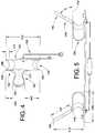
FIG. 4 andFIG. 5 , thecheek retractor 100 may have aheight 212 of about 2.1 inches and awidth 216 of about 2 inches. Theridge 140 may extend from theexterior side 120 into the mouth for alateral distance 214 of about 2 inches. FIG. 6 depicts another embodiment of acheek retractor 100 suitable for use in thedental apparatus 10. In this embodiment, there is nogroove 150 on theridge 140. Rather, theLEDs 160 are embedded into theridge 140. Theridge 140 has a smoothinner surface 300 which is made from a substantially transparent material that allows the LED light to shine through theinner surface 300 and illuminate the oral cavity. In embodiments, the material has a transparency (%T) of at least 90%, as measured by ASTM D1003. Many known materials meet this requirement, such as acrylic, polyester, epoxy, urethane, polycarbonate, and nylon resins.- In other embodiments shown in
FIG. 7 , theridge 140 has a raisedinner surface 302 instead, with theLEDs 160 still being embedded into theridge 140. In bothFIG. 6 andFIG. 7 , the LEDs can be connected to thepower cord 162 ofFIG. 1 . It should be noted that theLEDs 160 are placed along acenterline 304 of theridge 140. - Stenson's duct opens upon the inner surface of the cheek by a small orifice opposite the first or second molar tooth of the upper jaw. As seen in
FIG. 4 , theridge 140 may be offset towards thesuperior edge 330 of theretractor 100 or thetrough 110, and away from theinferior edge 340. Put another way, the ridge is closer to thesuperior edge 330 than theinferior edge 340. This offset allows theridge 140 to cover Stenson's duct, reducing the amount of saliva actually introduced into the oral cavity or at least redirecting the saliva along the inner surface of the cheek. The distance between theridge 140 and thesuperior edge 330 can be considered thesuperior height 335, and the distance between theridge 140 and theinferior edge 330 can be considered theinferior height 345. Thesuperior height 335 can be about 0.3 inches. Theinferior height 345 can be about 0.7 inches. In other embodiments, the ratio of thesuperior height 335 to theinferior height 345 is from about 0.2 to about 0.8, including about 0.4. It should be noted that bothretractors retractors retractor 20 is considered a left retractor, while theother retractor 30 is considered a right retractor. - Regarding
FIG. 8 , it is also contemplated that in some embodiments, the tworetractors Y connector 176. Put another way, thepower cords 162 of the two cheek retractors are joined together to form a Y connection. Theexternal control system 170 then needs only one socket into which the Y connector is plugged. Another advantage of these embodiments is that the combination of the retractors, power cords, and Y connector provide directionality to the assembly and it is clear which retractor should be attached to which end of theflexible arm 40. - The various parts of the dental apparatus can be made by methods known in the art. For example, molds can be made for the desired shapes of the retractors and arms. Molten polymer is poured into the molds and then cooled into solid form to form the retractor. The retractor is removed from the molds and LEDs are attached to the retractors using fasteners or adhesives such as glue. Alternatively, the LEDs are placed in the mold and the resin is poured into the mold to encase or embed the LEDs. As yet another alternative, a mold is made containing a groove. The LEDs are then placed into the groove, and resin is then poured to fill in the groove and encase or embed the LEDs. Generally, the
trough 110 andridge 140 of the retractor are made from the same material for ease of manufacture. The material used to make the retractor should be a biocompatible and/or medical grade polymeric material. Desirably, the material has low or zero water absorption, i.e. does not absorb water. - The apparatuses of the present disclosure have been described with reference to exemplary embodiments. Obviously, modifications and alterations will occur to others upon reading and understanding the preceding detailed description. It is intended that the exemplary embodiments be construed as including all such modifications and alterations insofar as they come within the scope of the appended claims.
Claims (11)
- A dental apparatus for retracting and illuminating the oral cavity of a patient, comprising:two cheek retractors (20; 30; 100); anda flexible arm (40) connecting the two retractors (20; 30; 100);wherein both of the two cheek retractors (20; 30; 100) comprise:a U-shaped trough (110), the trough (110) having an interior side (130) and an exterior side (120), two ends (310, 312), and a nadir (314);a ridge (140) extending transversely from the interior side (130) of the trough (110) in a longitudinal direction away from the arm (40);a joint (125) on the exterior side (120) of the trough (110) for connecting the retractors (20; 30; 100) to the arm (40),characterised in that the retractors (20; 30; 100) can be separated from the arm (40);in that an inner surface of the ridge (140) has a groove (150) formed within the ridge (140) that extends between a base (148) of the ridge (140) and an end (146) of the ridge (140) along a centerline (304) of the ridge (140), the base (148) of the ridge (140) connecting to the trough (110); andin that multiple light-emitting diodes (LED) (160) are embedded in the groove (150) within the ridge (140) in only a single row extending from the base (148) of the ridge (140) to the end (146) of the ridge (140).
- The dental apparatus of claim 1, wherein the ridge (140) is offset towards a superior edge (330) of the retractor (20; 30; 100).
- The dental apparatus of claim 1, further comprising a power cord (162; 178) for powering the multiple LEDs (160), the power cord (162; 178) extending from an exterior side (120) of the trough (110).
- The dental apparatus of claim 1, wherein the angle between the U-shaped trough (110) and the ridge (140) is from about 50° to about 70°.
- The dental apparatus of claim 1, wherein the ridge (140) has a smooth inner surface (300).
- The dental apparatus of claim 1, wherein the ridge (140) has a raised inner surface (302).
- The dental apparatus of claim 1, wherein the ridge (140) comprises a substantially transparent material through which said multiple LEDs (160) can transmit light.
- The dental apparatus of claim 1, further comprising:an external control system (170);wherein each cheek retractor (20; 30; 100) comprises:a power cord (162; 178) extending from an exterior side (120) of the trough (110) for powering the multiple LEDs (160); andwherein the joint (125) has a slot extending from the nadir (314) away from the two ends (310, 312) of the trough (110);wherein the arm (40) has two ends (46, 48), each end having a tab (44) that engages the slot (129) on the joint (125) to connect the cheek retractor (20; 30; 100) to the arm (40);wherein the external control system (170) includes a battery for powering the at least one LED (160) on each cheek retractor (20; 30; 100).
- The dental apparatus of claim 8, wherein the power cords (162; 178) of the two cheek retractors (20; 30; 100) are joined together to form a Y connection, integrally connecting the two retractors (20; 30; 100).
- The dental apparatus of claim 8, wherein the ridge (140) has a smooth inner surface (300).
- The dental apparatus of claim 10, wherein the ridge (140) comprises a substantially transparent material through which said multiple LEDs (160) can transmit light.
Applications Claiming Priority (2)
| Application Number | Priority Date | Filing Date | Title |
|---|---|---|---|
| US15194809P | 2009-02-12 | 2009-02-12 | |
| PCT/US2010/024033WO2010093877A1 (en) | 2009-02-12 | 2010-02-12 | Illuminated dental retractor |
Publications (3)
| Publication Number | Publication Date |
|---|---|
| EP2395903A1 EP2395903A1 (en) | 2011-12-21 |
| EP2395903A4 EP2395903A4 (en) | 2012-10-03 |
| EP2395903B1true EP2395903B1 (en) | 2016-04-20 |
Family
ID=42540700
Family Applications (1)
| Application Number | Title | Priority Date | Filing Date |
|---|---|---|---|
| EP10741773.5ANot-in-forceEP2395903B1 (en) | 2009-02-12 | 2010-02-12 | Illuminated dental retractor |
Country Status (4)
| Country | Link |
|---|---|
| US (2) | US8419428B2 (en) |
| EP (1) | EP2395903B1 (en) |
| CA (1) | CA2752638C (en) |
| WO (1) | WO2010093877A1 (en) |
Cited By (1)
| Publication number | Priority date | Publication date | Assignee | Title |
|---|---|---|---|---|
| EP3750504A1 (en) | 2019-06-14 | 2020-12-16 | Heiko Baumgartner | Mobile surgical light |
Families Citing this family (60)
| Publication number | Priority date | Publication date | Assignee | Title |
|---|---|---|---|---|
| US8765031B2 (en) | 2009-08-13 | 2014-07-01 | Align Technology, Inc. | Method of forming a dental appliance |
| US9211166B2 (en) | 2010-04-30 | 2015-12-15 | Align Technology, Inc. | Individualized orthodontic treatment index |
| US8376743B1 (en)* | 2011-10-18 | 2013-02-19 | King Saud University | Oral retractor |
| US9375300B2 (en) | 2012-02-02 | 2016-06-28 | Align Technology, Inc. | Identifying forces on a tooth |
| WO2014072976A1 (en)* | 2012-11-08 | 2014-05-15 | Emodi Omri | Intracavity illumination device |
| EP2967758B1 (en)* | 2013-03-11 | 2020-10-07 | Planmeca Oy | Modular assembly for dental applications |
| USD938095S1 (en) | 2013-04-01 | 2021-12-07 | Pathy Medical, Llc | Lighting device |
| RU2705046C2 (en) | 2013-04-01 | 2019-11-01 | Винод В. ПАТХИ | Lighting device |
| US10449016B2 (en) | 2014-09-19 | 2019-10-22 | Align Technology, Inc. | Arch adjustment appliance |
| US9610141B2 (en) | 2014-09-19 | 2017-04-04 | Align Technology, Inc. | Arch expanding appliance |
| US10504386B2 (en) | 2015-01-27 | 2019-12-10 | Align Technology, Inc. | Training method and system for oral-cavity-imaging-and-modeling equipment |
| EP4335494A3 (en)* | 2015-02-27 | 2024-05-15 | Colgate-Palmolive Company | Oral treatment system |
| US20170065268A1 (en)* | 2015-09-04 | 2017-03-09 | Thompson Surgical Instruments, Inc. | Surgical retractor with asymmetric blade |
| US11931222B2 (en) | 2015-11-12 | 2024-03-19 | Align Technology, Inc. | Dental attachment formation structures |
| US11554000B2 (en) | 2015-11-12 | 2023-01-17 | Align Technology, Inc. | Dental attachment formation structure |
| US11103330B2 (en) | 2015-12-09 | 2021-08-31 | Align Technology, Inc. | Dental attachment placement structure |
| US11596502B2 (en) | 2015-12-09 | 2023-03-07 | Align Technology, Inc. | Dental attachment placement structure |
| US10383705B2 (en) | 2016-06-17 | 2019-08-20 | Align Technology, Inc. | Orthodontic appliance performance monitor |
| WO2017218947A1 (en) | 2016-06-17 | 2017-12-21 | Align Technology, Inc. | Intraoral appliances with sensing |
| US10507087B2 (en) | 2016-07-27 | 2019-12-17 | Align Technology, Inc. | Methods and apparatuses for forming a three-dimensional volumetric model of a subject's teeth |
| CA3030676A1 (en) | 2016-07-27 | 2018-02-01 | Align Technology, Inc. | Intraoral scanner with dental diagnostics capabilities |
| WO2018102770A1 (en) | 2016-12-02 | 2018-06-07 | Align Technology, Inc. | Force control, stop mechanism, regulating structure of removable arch adjustment appliance |
| EP3547952B1 (en) | 2016-12-02 | 2020-11-04 | Align Technology, Inc. | Palatal expander |
| US11026831B2 (en) | 2016-12-02 | 2021-06-08 | Align Technology, Inc. | Dental appliance features for speech enhancement |
| AU2017366755B2 (en) | 2016-12-02 | 2022-07-28 | Align Technology, Inc. | Methods and apparatuses for customizing rapid palatal expanders using digital models |
| US10548700B2 (en) | 2016-12-16 | 2020-02-04 | Align Technology, Inc. | Dental appliance etch template |
| US10779718B2 (en) | 2017-02-13 | 2020-09-22 | Align Technology, Inc. | Cheek retractor and mobile device holder |
| ES2774220T3 (en)* | 2017-02-13 | 2020-07-17 | Astradentium Health Tech S L | Auxiliary device for dental procedure |
| WO2018183358A1 (en) | 2017-03-27 | 2018-10-04 | Align Technology, Inc. | Apparatuses and methods assisting in dental therapies |
| US10613515B2 (en) | 2017-03-31 | 2020-04-07 | Align Technology, Inc. | Orthodontic appliances including at least partially un-erupted teeth and method of forming them |
| US11045283B2 (en) | 2017-06-09 | 2021-06-29 | Align Technology, Inc. | Palatal expander with skeletal anchorage devices |
| US10636522B2 (en) | 2017-06-21 | 2020-04-28 | SmileDirectClub LLC | Arrangements for intraoral scanning |
| US11337778B2 (en) | 2017-06-21 | 2022-05-24 | Sdc U.S. Smilepay Spv | Distributed system for fabricating dental aligners |
| US20180368941A1 (en) | 2017-06-21 | 2018-12-27 | SmileDirectClub LLC | Dental impression kit and methods therefor |
| US20180368954A1 (en) | 2017-06-21 | 2018-12-27 | SmileDirectClub LLC | Dental impression kit and methods therefor |
| US10639134B2 (en) | 2017-06-26 | 2020-05-05 | Align Technology, Inc. | Biosensor performance indicator for intraoral appliances |
| US10885521B2 (en) | 2017-07-17 | 2021-01-05 | Align Technology, Inc. | Method and apparatuses for interactive ordering of dental aligners |
| CN111107806B (en) | 2017-07-21 | 2022-04-19 | 阿莱恩技术有限公司 | Jaw profile anchoring |
| CN110996842B (en) | 2017-07-27 | 2022-10-14 | 阿莱恩技术有限公司 | Tooth Staining, Transparency and Glazing |
| US12274597B2 (en) | 2017-08-11 | 2025-04-15 | Align Technology, Inc. | Dental attachment template tray systems |
| US11116605B2 (en) | 2017-08-15 | 2021-09-14 | Align Technology, Inc. | Buccal corridor assessment and computation |
| US11123156B2 (en) | 2017-08-17 | 2021-09-21 | Align Technology, Inc. | Dental appliance compliance monitoring |
| US12171575B2 (en) | 2017-10-04 | 2024-12-24 | Align Technology, Inc. | Intraoral systems and methods for sampling soft-tissue |
| US10813720B2 (en) | 2017-10-05 | 2020-10-27 | Align Technology, Inc. | Interproximal reduction templates |
| CN111295153B (en) | 2017-10-31 | 2023-06-16 | 阿莱恩技术有限公司 | Dental appliance with selective bite loading and controlled tip staggering |
| CN119235481A (en) | 2017-11-01 | 2025-01-03 | 阿莱恩技术有限公司 | Automatic treatment planning |
| US11534974B2 (en) | 2017-11-17 | 2022-12-27 | Align Technology, Inc. | Customized fabrication of orthodontic retainers based on patient anatomy |
| US11219506B2 (en) | 2017-11-30 | 2022-01-11 | Align Technology, Inc. | Sensors for monitoring oral appliances |
| US11432908B2 (en) | 2017-12-15 | 2022-09-06 | Align Technology, Inc. | Closed loop adaptive orthodontic treatment methods and apparatuses |
| US10980613B2 (en) | 2017-12-29 | 2021-04-20 | Align Technology, Inc. | Augmented reality enhancements for dental practitioners |
| CN108245124B (en)* | 2018-01-25 | 2020-03-13 | 孙益虎 | Opening device for oral surgery |
| US10813727B2 (en) | 2018-01-26 | 2020-10-27 | Align Technology, Inc. | Diagnostic intraoral tracking |
| US11937991B2 (en) | 2018-03-27 | 2024-03-26 | Align Technology, Inc. | Dental attachment placement structure |
| EP3773320B1 (en) | 2018-04-11 | 2024-05-15 | Align Technology, Inc. | Releasable palatal expanders |
| FR3087644B1 (en)* | 2018-10-30 | 2022-06-10 | Dental Monitoring | ARTICULATED DENTAL PHOTO TAKING KIT |
| KR102336883B1 (en)* | 2019-05-09 | 2021-12-09 | 주식회사 아이오바이오 | Hood-type retractor |
| DE202019103344U1 (en) | 2019-06-14 | 2019-06-19 | Heiko Baumgartner | Mobile Surgical Light |
| CA3142564A1 (en)* | 2020-12-11 | 2022-06-11 | Xerosguard Inc. | Intra-oral appliance |
| WO2023220821A1 (en)* | 2022-05-17 | 2023-11-23 | Xerosguard Inc. | Intra-oral dental appliance |
| US20230397803A1 (en)* | 2022-06-13 | 2023-12-14 | Brian Halleck | Dental retractor |
Family Cites Families (20)
| Publication number | Priority date | Publication date | Assignee | Title |
|---|---|---|---|---|
| US4592344A (en)* | 1980-07-25 | 1986-06-03 | Scheer Peter M | Combination illuminator and lip and cheek expander |
| US5037298A (en)* | 1985-11-25 | 1991-08-06 | Hickham John J | Apparatus and improved process for removing saliva while retracting cheeks and lips |
| JPH0490753A (en)* | 1990-08-02 | 1992-03-24 | Hideyuki Takeuchi | Shadow-free lamp in oral cavity for dental use |
| US5775896A (en)* | 1995-03-10 | 1998-07-07 | Micron Dental Manufacturing, Inc. | Versatile operatory light system |
| US5711665A (en)* | 1995-12-19 | 1998-01-27 | Minnesota Mining & Manufacturing | Method and apparatus for bonding orthodontic brackets to teeth |
| US6022214A (en) | 1998-11-17 | 2000-02-08 | Hirsch; James A. | Intraoral illumination device and method of using the same |
| US6616447B1 (en)* | 2000-11-15 | 2003-09-09 | Biolase Technology, Inc. | Device for dental care and whitening |
| ITRI20030005A1 (en) | 2003-07-02 | 2005-01-03 | Vincenzo Gargiulo | ANATOMICAL MINI-CABLE ILLUMINATOR. |
| US20050239017A1 (en) | 2004-04-23 | 2005-10-27 | Lim Ki B | Ring-shaped illuminated mouth prop |
| US20050239018A1 (en) | 2004-04-27 | 2005-10-27 | Scott Green | Intraoral bite spacer and illumination apparatus |
| JP2005342072A (en)* | 2004-06-01 | 2005-12-15 | Futek Inc | Mouthpiece |
| US20060069316A1 (en)* | 2004-07-02 | 2006-03-30 | Discus Dental Impressions, Inc. | Retracting devices |
| ITBO20040443A1 (en)* | 2004-07-16 | 2004-10-16 | Cefla Coop | ORAL CABLE RETRACTOR |
| US7522322B2 (en) | 2004-08-19 | 2009-04-21 | Carestream Health, Inc. | Apparatus for dental shade measurement |
| US20060063979A1 (en)* | 2004-08-25 | 2006-03-23 | Kenneth Rosenblood | Retracting devices |
| TWM271549U (en) | 2005-01-13 | 2005-08-01 | Jian-Shin Yang | Oral cavity lighting device |
| JP2009512174A (en)* | 2005-10-17 | 2009-03-19 | デントゾーン カンパニー リミテッド | Oral lighting device |
| US20070156028A1 (en)* | 2005-12-29 | 2007-07-05 | Van Lue Stephen J | Magnetic surgical/oral retractor |
| US7597554B2 (en) | 2006-11-14 | 2009-10-06 | Enrique Fernandez Del Busto Ortega | Device for unilateral or bilateral illumination of oral cavity |
| GB0706741D0 (en)* | 2007-04-05 | 2007-05-16 | Smile Studio Uk Ltd | Method and apparatus for whitening teeth |
- 2010
- 2010-02-12EPEP10741773.5Apatent/EP2395903B1/ennot_activeNot-in-force
- 2010-02-12CACA2752638Apatent/CA2752638C/enactiveActive
- 2010-02-12WOPCT/US2010/024033patent/WO2010093877A1/enactiveApplication Filing
- 2010-02-12USUS12/704,846patent/US8419428B2/enactiveActive
- 2013
- 2013-04-12USUS13/861,500patent/US9259143B2/enactiveActive
Cited By (1)
| Publication number | Priority date | Publication date | Assignee | Title |
|---|---|---|---|---|
| EP3750504A1 (en) | 2019-06-14 | 2020-12-16 | Heiko Baumgartner | Mobile surgical light |
Also Published As
| Publication number | Publication date |
|---|---|
| US8419428B2 (en) | 2013-04-16 |
| US20100203466A1 (en) | 2010-08-12 |
| WO2010093877A1 (en) | 2010-08-19 |
| US9259143B2 (en) | 2016-02-16 |
| CA2752638A1 (en) | 2010-08-19 |
| CA2752638C (en) | 2016-10-25 |
| US20130230823A1 (en) | 2013-09-05 |
| EP2395903A1 (en) | 2011-12-21 |
| EP2395903A4 (en) | 2012-10-03 |
Similar Documents
| Publication | Publication Date | Title |
|---|---|---|
| EP2395903B1 (en) | Illuminated dental retractor | |
| US11903567B2 (en) | Body cavity illumination system | |
| US9730685B2 (en) | Surgical retractor with light | |
| EP1093765B1 (en) | Lighting device for dental or medical instrument | |
| ES2587366T3 (en) | Portable lighting device that can be fixed for surgical instruments | |
| US20190269312A1 (en) | Methods, devices, systems, assemblies, and kits for tissue retraction in an oral cavity | |
| US10405844B2 (en) | Surgical retractor with light | |
| US6379296B1 (en) | Medical lighting device | |
| US3916880A (en) | Device for holding open the mouth | |
| US20080113312A1 (en) | Device for unilateral or bilateral illumination of oral cavity | |
| US7611256B2 (en) | Illuminator for medical use | |
| US20090266368A1 (en) | Endoscopic bite block | |
| ES2821329T3 (en) | Lighting device | |
| ES2841065T3 (en) | Modular set for dental applications | |
| KR101601144B1 (en) | U-shaped oral tissue retractor for dental surgery | |
| CN215192516U (en) | Oral cavity photographic retractor | |
| JP2018143408A (en) | Cheek holding tool | |
| CN207005859U (en) | Cheek hold assembly | |
| CN201822840U (en) | Visual mouth gag | |
| KR200463289Y1 (en) | illumination apparatus | |
| KR101233040B1 (en) | Dental LED UNIT For Mouth Prop | |
| CN211355374U (en) | Electronic gastroscope | |
| TWM566557U (en) | Dental care device | |
| CN101966072B (en) | Visible oral cavity mouth gag |
Legal Events
| Date | Code | Title | Description |
|---|---|---|---|
| PUAI | Public reference made under article 153(3) epc to a published international application that has entered the european phase | Free format text:ORIGINAL CODE: 0009012 | |
| 17P | Request for examination filed | Effective date:20110909 | |
| AK | Designated contracting states | Kind code of ref document:A1 Designated state(s):AT BE BG CH CY CZ DE DK EE ES FI FR GB GR HR HU IE IS IT LI LT LU LV MC MK MT NL NO PL PT RO SE SI SK SM TR | |
| DAX | Request for extension of the european patent (deleted) | ||
| A4 | Supplementary search report drawn up and despatched | Effective date:20120904 | |
| RIC1 | Information provided on ipc code assigned before grant | Ipc:A61B 1/32 20060101AFI20120829BHEP | |
| 17Q | First examination report despatched | Effective date:20130502 | |
| GRAP | Despatch of communication of intention to grant a patent | Free format text:ORIGINAL CODE: EPIDOSNIGR1 | |
| INTG | Intention to grant announced | Effective date:20151022 | |
| GRAS | Grant fee paid | Free format text:ORIGINAL CODE: EPIDOSNIGR3 | |
| GRAA | (expected) grant | Free format text:ORIGINAL CODE: 0009210 | |
| AK | Designated contracting states | Kind code of ref document:B1 Designated state(s):AT BE BG CH CY CZ DE DK EE ES FI FR GB GR HR HU IE IS IT LI LT LU LV MC MK MT NL NO PL PT RO SE SI SK SM TR | |
| REG | Reference to a national code | Ref country code:GB Ref legal event code:FG4D | |
| REG | Reference to a national code | Ref country code:CH Ref legal event code:EP | |
| REG | Reference to a national code | Ref country code:AT Ref legal event code:REF Ref document number:791431 Country of ref document:AT Kind code of ref document:T Effective date:20160515 | |
| REG | Reference to a national code | Ref country code:IE Ref legal event code:FG4D | |
| REG | Reference to a national code | Ref country code:DE Ref legal event code:R096 Ref document number:602010032507 Country of ref document:DE | |
| REG | Reference to a national code | Ref country code:LT Ref legal event code:MG4D | |
| REG | Reference to a national code | Ref country code:AT Ref legal event code:MK05 Ref document number:791431 Country of ref document:AT Kind code of ref document:T Effective date:20160420 | |
| REG | Reference to a national code | Ref country code:NL Ref legal event code:MP Effective date:20160420 | |
| PG25 | Lapsed in a contracting state [announced via postgrant information from national office to epo] | Ref country code:LT Free format text:LAPSE BECAUSE OF FAILURE TO SUBMIT A TRANSLATION OF THE DESCRIPTION OR TO PAY THE FEE WITHIN THE PRESCRIBED TIME-LIMIT Effective date:20160420 Ref country code:NO Free format text:LAPSE BECAUSE OF FAILURE TO SUBMIT A TRANSLATION OF THE DESCRIPTION OR TO PAY THE FEE WITHIN THE PRESCRIBED TIME-LIMIT Effective date:20160720 Ref country code:NL Free format text:LAPSE BECAUSE OF FAILURE TO SUBMIT A TRANSLATION OF THE DESCRIPTION OR TO PAY THE FEE WITHIN THE PRESCRIBED TIME-LIMIT Effective date:20160420 Ref country code:FI Free format text:LAPSE BECAUSE OF FAILURE TO SUBMIT A TRANSLATION OF THE DESCRIPTION OR TO PAY THE FEE WITHIN THE PRESCRIBED TIME-LIMIT Effective date:20160420 Ref country code:PL Free format text:LAPSE BECAUSE OF FAILURE TO SUBMIT A TRANSLATION OF THE DESCRIPTION OR TO PAY THE FEE WITHIN THE PRESCRIBED TIME-LIMIT Effective date:20160420 | |
| PG25 | Lapsed in a contracting state [announced via postgrant information from national office to epo] | Ref country code:LV Free format text:LAPSE BECAUSE OF FAILURE TO SUBMIT A TRANSLATION OF THE DESCRIPTION OR TO PAY THE FEE WITHIN THE PRESCRIBED TIME-LIMIT Effective date:20160420 Ref country code:SE Free format text:LAPSE BECAUSE OF FAILURE TO SUBMIT A TRANSLATION OF THE DESCRIPTION OR TO PAY THE FEE WITHIN THE PRESCRIBED TIME-LIMIT Effective date:20160420 Ref country code:AT Free format text:LAPSE BECAUSE OF FAILURE TO SUBMIT A TRANSLATION OF THE DESCRIPTION OR TO PAY THE FEE WITHIN THE PRESCRIBED TIME-LIMIT Effective date:20160420 Ref country code:PT Free format text:LAPSE BECAUSE OF FAILURE TO SUBMIT A TRANSLATION OF THE DESCRIPTION OR TO PAY THE FEE WITHIN THE PRESCRIBED TIME-LIMIT Effective date:20160822 Ref country code:HR Free format text:LAPSE BECAUSE OF FAILURE TO SUBMIT A TRANSLATION OF THE DESCRIPTION OR TO PAY THE FEE WITHIN THE PRESCRIBED TIME-LIMIT Effective date:20160420 Ref country code:ES Free format text:LAPSE BECAUSE OF FAILURE TO SUBMIT A TRANSLATION OF THE DESCRIPTION OR TO PAY THE FEE WITHIN THE PRESCRIBED TIME-LIMIT Effective date:20160420 Ref country code:GR Free format text:LAPSE BECAUSE OF FAILURE TO SUBMIT A TRANSLATION OF THE DESCRIPTION OR TO PAY THE FEE WITHIN THE PRESCRIBED TIME-LIMIT Effective date:20160721 | |
| PG25 | Lapsed in a contracting state [announced via postgrant information from national office to epo] | Ref country code:IT Free format text:LAPSE BECAUSE OF FAILURE TO SUBMIT A TRANSLATION OF THE DESCRIPTION OR TO PAY THE FEE WITHIN THE PRESCRIBED TIME-LIMIT Effective date:20160420 Ref country code:BE Free format text:LAPSE BECAUSE OF FAILURE TO SUBMIT A TRANSLATION OF THE DESCRIPTION OR TO PAY THE FEE WITHIN THE PRESCRIBED TIME-LIMIT Effective date:20160420 | |
| REG | Reference to a national code | Ref country code:FR Ref legal event code:PLFP Year of fee payment:8 | |
| REG | Reference to a national code | Ref country code:DE Ref legal event code:R097 Ref document number:602010032507 Country of ref document:DE | |
| PG25 | Lapsed in a contracting state [announced via postgrant information from national office to epo] | Ref country code:DK Free format text:LAPSE BECAUSE OF FAILURE TO SUBMIT A TRANSLATION OF THE DESCRIPTION OR TO PAY THE FEE WITHIN THE PRESCRIBED TIME-LIMIT Effective date:20160420 Ref country code:RO Free format text:LAPSE BECAUSE OF FAILURE TO SUBMIT A TRANSLATION OF THE DESCRIPTION OR TO PAY THE FEE WITHIN THE PRESCRIBED TIME-LIMIT Effective date:20160420 Ref country code:EE Free format text:LAPSE BECAUSE OF FAILURE TO SUBMIT A TRANSLATION OF THE DESCRIPTION OR TO PAY THE FEE WITHIN THE PRESCRIBED TIME-LIMIT Effective date:20160420 Ref country code:CZ Free format text:LAPSE BECAUSE OF FAILURE TO SUBMIT A TRANSLATION OF THE DESCRIPTION OR TO PAY THE FEE WITHIN THE PRESCRIBED TIME-LIMIT Effective date:20160420 Ref country code:SK Free format text:LAPSE BECAUSE OF FAILURE TO SUBMIT A TRANSLATION OF THE DESCRIPTION OR TO PAY THE FEE WITHIN THE PRESCRIBED TIME-LIMIT Effective date:20160420 | |
| PLBE | No opposition filed within time limit | Free format text:ORIGINAL CODE: 0009261 | |
| STAA | Information on the status of an ep patent application or granted ep patent | Free format text:STATUS: NO OPPOSITION FILED WITHIN TIME LIMIT | |
| PG25 | Lapsed in a contracting state [announced via postgrant information from national office to epo] | Ref country code:SM Free format text:LAPSE BECAUSE OF FAILURE TO SUBMIT A TRANSLATION OF THE DESCRIPTION OR TO PAY THE FEE WITHIN THE PRESCRIBED TIME-LIMIT Effective date:20160420 | |
| 26N | No opposition filed | Effective date:20170123 | |
| PG25 | Lapsed in a contracting state [announced via postgrant information from national office to epo] | Ref country code:SI Free format text:LAPSE BECAUSE OF FAILURE TO SUBMIT A TRANSLATION OF THE DESCRIPTION OR TO PAY THE FEE WITHIN THE PRESCRIBED TIME-LIMIT Effective date:20160420 | |
| PG25 | Lapsed in a contracting state [announced via postgrant information from national office to epo] | Ref country code:MC Free format text:LAPSE BECAUSE OF FAILURE TO SUBMIT A TRANSLATION OF THE DESCRIPTION OR TO PAY THE FEE WITHIN THE PRESCRIBED TIME-LIMIT Effective date:20160420 | |
| REG | Reference to a national code | Ref country code:CH Ref legal event code:PL | |
| PG25 | Lapsed in a contracting state [announced via postgrant information from national office to epo] | Ref country code:LI Free format text:LAPSE BECAUSE OF NON-PAYMENT OF DUE FEES Effective date:20170228 Ref country code:CH Free format text:LAPSE BECAUSE OF NON-PAYMENT OF DUE FEES Effective date:20170228 | |
| REG | Reference to a national code | Ref country code:IE Ref legal event code:MM4A | |
| PG25 | Lapsed in a contracting state [announced via postgrant information from national office to epo] | Ref country code:LU Free format text:LAPSE BECAUSE OF NON-PAYMENT OF DUE FEES Effective date:20170212 | |
| REG | Reference to a national code | Ref country code:FR Ref legal event code:PLFP Year of fee payment:9 | |
| PG25 | Lapsed in a contracting state [announced via postgrant information from national office to epo] | Ref country code:IE Free format text:LAPSE BECAUSE OF NON-PAYMENT OF DUE FEES Effective date:20170212 | |
| PG25 | Lapsed in a contracting state [announced via postgrant information from national office to epo] | Ref country code:MT Free format text:LAPSE BECAUSE OF NON-PAYMENT OF DUE FEES Effective date:20170212 | |
| PG25 | Lapsed in a contracting state [announced via postgrant information from national office to epo] | Ref country code:HU Free format text:LAPSE BECAUSE OF FAILURE TO SUBMIT A TRANSLATION OF THE DESCRIPTION OR TO PAY THE FEE WITHIN THE PRESCRIBED TIME-LIMIT; INVALID AB INITIO Effective date:20100212 | |
| PG25 | Lapsed in a contracting state [announced via postgrant information from national office to epo] | Ref country code:BG Free format text:LAPSE BECAUSE OF FAILURE TO SUBMIT A TRANSLATION OF THE DESCRIPTION OR TO PAY THE FEE WITHIN THE PRESCRIBED TIME-LIMIT Effective date:20160420 | |
| PG25 | Lapsed in a contracting state [announced via postgrant information from national office to epo] | Ref country code:CY Free format text:LAPSE BECAUSE OF NON-PAYMENT OF DUE FEES Effective date:20160420 | |
| PG25 | Lapsed in a contracting state [announced via postgrant information from national office to epo] | Ref country code:MK Free format text:LAPSE BECAUSE OF FAILURE TO SUBMIT A TRANSLATION OF THE DESCRIPTION OR TO PAY THE FEE WITHIN THE PRESCRIBED TIME-LIMIT Effective date:20160420 | |
| PG25 | Lapsed in a contracting state [announced via postgrant information from national office to epo] | Ref country code:TR Free format text:LAPSE BECAUSE OF FAILURE TO SUBMIT A TRANSLATION OF THE DESCRIPTION OR TO PAY THE FEE WITHIN THE PRESCRIBED TIME-LIMIT Effective date:20160420 | |
| PG25 | Lapsed in a contracting state [announced via postgrant information from national office to epo] | Ref country code:IS Free format text:LAPSE BECAUSE OF FAILURE TO SUBMIT A TRANSLATION OF THE DESCRIPTION OR TO PAY THE FEE WITHIN THE PRESCRIBED TIME-LIMIT Effective date:20160820 | |
| PGFP | Annual fee paid to national office [announced via postgrant information from national office to epo] | Ref country code:FR Payment date:20230127 Year of fee payment:14 | |
| PGFP | Annual fee paid to national office [announced via postgrant information from national office to epo] | Ref country code:GB Payment date:20230208 Year of fee payment:14 Ref country code:DE Payment date:20230210 Year of fee payment:14 | |
| P01 | Opt-out of the competence of the unified patent court (upc) registered | Effective date:20230524 | |
| REG | Reference to a national code | Ref country code:DE Ref legal event code:R119 Ref document number:602010032507 Country of ref document:DE | |
| GBPC | Gb: european patent ceased through non-payment of renewal fee | Effective date:20240212 | |
| PG25 | Lapsed in a contracting state [announced via postgrant information from national office to epo] | Ref country code:DE Free format text:LAPSE BECAUSE OF NON-PAYMENT OF DUE FEES Effective date:20240903 | |
| PG25 | Lapsed in a contracting state [announced via postgrant information from national office to epo] | Ref country code:GB Free format text:LAPSE BECAUSE OF NON-PAYMENT OF DUE FEES Effective date:20240212 | |
| PG25 | Lapsed in a contracting state [announced via postgrant information from national office to epo] | Ref country code:FR Free format text:LAPSE BECAUSE OF NON-PAYMENT OF DUE FEES Effective date:20240229 | |
| PG25 | Lapsed in a contracting state [announced via postgrant information from national office to epo] | Ref country code:GB Free format text:LAPSE BECAUSE OF NON-PAYMENT OF DUE FEES Effective date:20240212 Ref country code:FR Free format text:LAPSE BECAUSE OF NON-PAYMENT OF DUE FEES Effective date:20240229 Ref country code:DE Free format text:LAPSE BECAUSE OF NON-PAYMENT OF DUE FEES Effective date:20240903 |