EP2394926B1 - Child safe stopper - Google Patents
Child safe stopperDownload PDFInfo
- Publication number
- EP2394926B1 EP2394926B1EP10305608.1AEP10305608AEP2394926B1EP 2394926 B1EP2394926 B1EP 2394926B1EP 10305608 AEP10305608 AEP 10305608AEP 2394926 B1EP2394926 B1EP 2394926B1
- Authority
- EP
- European Patent Office
- Prior art keywords
- moving element
- moving
- stopper
- body element
- container
- Prior art date
- Legal status (The legal status is an assumption and is not a legal conclusion. Google has not performed a legal analysis and makes no representation as to the accuracy of the status listed.)
- Active
Links
Images


Classifications
- B—PERFORMING OPERATIONS; TRANSPORTING
- B65—CONVEYING; PACKING; STORING; HANDLING THIN OR FILAMENTARY MATERIAL
- B65D—CONTAINERS FOR STORAGE OR TRANSPORT OF ARTICLES OR MATERIALS, e.g. BAGS, BARRELS, BOTTLES, BOXES, CANS, CARTONS, CRATES, DRUMS, JARS, TANKS, HOPPERS, FORWARDING CONTAINERS; ACCESSORIES, CLOSURES, OR FITTINGS THEREFOR; PACKAGING ELEMENTS; PACKAGES
- B65D50/00—Closures with means for discouraging unauthorised opening or removal thereof, with or without indicating means, e.g. child-proof closures
- B65D50/02—Closures with means for discouraging unauthorised opening or removal thereof, with or without indicating means, e.g. child-proof closures openable or removable by the combination of plural actions
- B65D50/04—Closures with means for discouraging unauthorised opening or removal thereof, with or without indicating means, e.g. child-proof closures openable or removable by the combination of plural actions requiring the combination of simultaneous actions, e.g. depressing and turning, lifting and turning, maintaining a part and turning another one
- B65D50/045—Closures with means for discouraging unauthorised opening or removal thereof, with or without indicating means, e.g. child-proof closures openable or removable by the combination of plural actions requiring the combination of simultaneous actions, e.g. depressing and turning, lifting and turning, maintaining a part and turning another one where one action elastically deforms or deflects at least part of the closure, the container or an intermediate element, e.g. a ring
- B—PERFORMING OPERATIONS; TRANSPORTING
- B29—WORKING OF PLASTICS; WORKING OF SUBSTANCES IN A PLASTIC STATE IN GENERAL
- B29C—SHAPING OR JOINING OF PLASTICS; SHAPING OF MATERIAL IN A PLASTIC STATE, NOT OTHERWISE PROVIDED FOR; AFTER-TREATMENT OF THE SHAPED PRODUCTS, e.g. REPAIRING
- B29C45/00—Injection moulding, i.e. forcing the required volume of moulding material through a nozzle into a closed mould; Apparatus therefor
- B29C45/14—Injection moulding, i.e. forcing the required volume of moulding material through a nozzle into a closed mould; Apparatus therefor incorporating preformed parts or layers, e.g. injection moulding around inserts or for coating articles
- B—PERFORMING OPERATIONS; TRANSPORTING
- B65—CONVEYING; PACKING; STORING; HANDLING THIN OR FILAMENTARY MATERIAL
- B65D—CONTAINERS FOR STORAGE OR TRANSPORT OF ARTICLES OR MATERIALS, e.g. BAGS, BARRELS, BOTTLES, BOXES, CANS, CARTONS, CRATES, DRUMS, JARS, TANKS, HOPPERS, FORWARDING CONTAINERS; ACCESSORIES, CLOSURES, OR FITTINGS THEREFOR; PACKAGING ELEMENTS; PACKAGES
- B65D39/00—Closures arranged within necks or pouring openings or in discharge apertures, e.g. stoppers
- B65D39/0052—Closures arranged within necks or pouring openings or in discharge apertures, e.g. stoppers made in more than one piece
- B65D39/007—Plastic cap-shaped hollow plugs
- B—PERFORMING OPERATIONS; TRANSPORTING
- B65—CONVEYING; PACKING; STORING; HANDLING THIN OR FILAMENTARY MATERIAL
- B65D—CONTAINERS FOR STORAGE OR TRANSPORT OF ARTICLES OR MATERIALS, e.g. BAGS, BARRELS, BOTTLES, BOXES, CANS, CARTONS, CRATES, DRUMS, JARS, TANKS, HOPPERS, FORWARDING CONTAINERS; ACCESSORIES, CLOSURES, OR FITTINGS THEREFOR; PACKAGING ELEMENTS; PACKAGES
- B65D51/00—Closures not otherwise provided for
- B65D51/24—Closures not otherwise provided for combined or co-operating with auxiliary devices for non-closing purposes
- B65D51/28—Closures not otherwise provided for combined or co-operating with auxiliary devices for non-closing purposes with auxiliary containers for additional articles or materials
- B65D51/30—Closures not otherwise provided for combined or co-operating with auxiliary devices for non-closing purposes with auxiliary containers for additional articles or materials for desiccators
- B—PERFORMING OPERATIONS; TRANSPORTING
- B29—WORKING OF PLASTICS; WORKING OF SUBSTANCES IN A PLASTIC STATE IN GENERAL
- B29C—SHAPING OR JOINING OF PLASTICS; SHAPING OF MATERIAL IN A PLASTIC STATE, NOT OTHERWISE PROVIDED FOR; AFTER-TREATMENT OF THE SHAPED PRODUCTS, e.g. REPAIRING
- B29C45/00—Injection moulding, i.e. forcing the required volume of moulding material through a nozzle into a closed mould; Apparatus therefor
- B29C45/0053—Injection moulding, i.e. forcing the required volume of moulding material through a nozzle into a closed mould; Apparatus therefor combined with a final operation, e.g. shaping
- B—PERFORMING OPERATIONS; TRANSPORTING
- B65—CONVEYING; PACKING; STORING; HANDLING THIN OR FILAMENTARY MATERIAL
- B65D—CONTAINERS FOR STORAGE OR TRANSPORT OF ARTICLES OR MATERIALS, e.g. BAGS, BARRELS, BOTTLES, BOXES, CANS, CARTONS, CRATES, DRUMS, JARS, TANKS, HOPPERS, FORWARDING CONTAINERS; ACCESSORIES, CLOSURES, OR FITTINGS THEREFOR; PACKAGING ELEMENTS; PACKAGES
- B65D2215/00—Child-proof means
- B65D2215/04—Child-proof means requiring the combination of different actions in succession
- B—PERFORMING OPERATIONS; TRANSPORTING
- B65—CONVEYING; PACKING; STORING; HANDLING THIN OR FILAMENTARY MATERIAL
- B65D—CONTAINERS FOR STORAGE OR TRANSPORT OF ARTICLES OR MATERIALS, e.g. BAGS, BARRELS, BOTTLES, BOXES, CANS, CARTONS, CRATES, DRUMS, JARS, TANKS, HOPPERS, FORWARDING CONTAINERS; ACCESSORIES, CLOSURES, OR FITTINGS THEREFOR; PACKAGING ELEMENTS; PACKAGES
- B65D2401/00—Tamper-indicating means
- B65D2401/15—Tearable part of the closure
- B65D2401/25—Non-metallic tear-off strips
- Y—GENERAL TAGGING OF NEW TECHNOLOGICAL DEVELOPMENTS; GENERAL TAGGING OF CROSS-SECTIONAL TECHNOLOGIES SPANNING OVER SEVERAL SECTIONS OF THE IPC; TECHNICAL SUBJECTS COVERED BY FORMER USPC CROSS-REFERENCE ART COLLECTIONS [XRACs] AND DIGESTS
- Y10—TECHNICAL SUBJECTS COVERED BY FORMER USPC
- Y10T—TECHNICAL SUBJECTS COVERED BY FORMER US CLASSIFICATION
- Y10T29/00—Metal working
- Y10T29/49—Method of mechanical manufacture
- Y10T29/49826—Assembling or joining
Definitions
- the present inventionpertains to a stopper for closing a dispensing opening of a container, the stopper having childproof characteristics.
- Stoppers for closing the dispensing openings of containersare generally known.
- containers which are intended to contain powders, granulates, pills, tablets, dragées or any other products in the pharmaceutical or chemical domainit might be crucial that their respective stoppers cannot be opened or removed by children. This is in particular the case for containers which contain medicine or other substances that can be dangerous when taken in an uncontrolled manner.
- stopperswhich include a tamper-evident member which has to be removed or fractured from the stopper and/or the container before the dispensing opening of the container can be opened for the first time.
- tamper-evident membersare typically provided in the form of a tear-off ring, a tear-off strip or in the form of foils.
- Some of these conceptsrequire that the stopper be opened according to a procedure which requires at least two consecutive complex movements. For example, the user has to push the container in order to gain access to an edge of a stopper which then has to be pushed in a direction perpendicular to the initial pushing direction in order to remove the stopper from the container.
- the slideIn order to open the stopper according to this concept, the slide has to be pushed on its outer circumferential edge in order to provide, at the other side thereof, an edge to lift the stopper and remove it from the dispensing opening.
- DE 10 2006 018 449describes a stopper according to the preamble of claim 1 engaging with a ring-shaped neck in a press fit in a container. It has a circular bottom section which seals the container opening, and a head section which rises above the container and encompasses a slide that extends through the center of the head section, the rim of the head section having a maximum diameter that does not exceed the external diameter of the container opening.
- the stopperis characterized in that the slide can be pushed against the force of a spring in one direction over the rim of the container and, when released, returns to its retracted initial position as a result of the spring resistance. The stopper cannot be removed from the container by small children.
- the stopperhas a body element for closing the dispensing opening, the body element having a top face and a bottom face, wherein the bottom face is directed towards the inside of the container.
- a moving elementis provided which is situated at the top face of the body element, wherein the moving element is movable relative to the body element from an initial position in which the moving element does not extend beyond the outer extension of the top face in the plane of the top face of the body element, to an opening position in which the moving element is slid relative to the body element to extend at least partly beyond the outer extension of the top face of the body element in the plane of the body element.
- the moving elementprovides, in the opening position, a gripping surface for a user to remove the body element from the dispensing opening.
- the moving elementsubstantially covers the entire top face of the body element in the initial position.
- a moving elementin the form as stated above, namely that the moving element is situated on the top face of the body element and substantially covers the entire top face of the body element in the initial position, there are several advantages over the known solutions, from a handling perspective, from a childproof perspective as well as from a design perspective. In particular, when viewing the stopper from the top, only the moving element is visible. In particular if the moving element is symmetric it is not obvious that there is a moving element and in which direction it has to be operated.
- the useris now free to choose the location where to push the moving element in order to move it from its initial position to the opening position, because the user can touch the moving element in any position on the top surface of the moving element.
- the userwas required to push the slide at a specific position at the edge of the slide, which could be cumbersome to find or to reach, in particular when trying to push it the right position for people with large hands.
- the moving element according to the present disclosurehas the advantage that the user has an extended surface, to which he can connect, preferably frictionally, with his fingers in order to move the moving element from the initial position to the opening position. This greatly improves the handling in terms of user friendliness.
- the moving elementwhich represents substantially the entire top face of the stopper, is movable at all.
- the moving elementappears to be solitary with the remainder of the container and not movable at all.
- a specific direction into which the moving element can be moved beyond the outer extension of the body elementis not immediately apparent because a defined direction cannot be gathered from the appearance of the top surface of the stopper alone, in particular as the moving element substantially covers the entire top surface. Accordingly, it becomes more difficult for a small child to figure out whether the moving element can be moved at all, and into which direction the moving element can be moved after the child has eventually figured out that the moving element is movable at all.
- the movement of the movable element for moving it between the initial position and the opening positioncan either be a linear movement, preferably in the form of a sliding movement, or a rotating movement. Naturally, sliding and rotating movements can be combined. In case a sliding movement is chosen, the movable element can also be regarded a sliding element.
- the moving element and the body element as described abovecan be manufactured more easily, in particular by injection moulding, than the stoppers of the prior art.
- the stoppersare easier to assemble than the stoppers of the prior art. Accordingly, from a design perspective, the stopper according to the present invention has the advantage that it is easier to produce, manufacture and assemble.
- the body elementincludes a desiccant chamber at its bottom face, in particular directed towards the inside of the container.
- a desiccant chamberenables the provision of a desiccant to be filled into the stopper and/or to be inserted into the body element of the stopper in order to desiccate the contents of the container.
- the body element of the stoppermay include a bottom face defining a hollow space into which an active substance can be filled which is intended to regulate the gaseous atmosphere inside of the volume of the container.
- the body elementcan also be made at least partly from a desiccant material, and/or an oxygen absorber and/or a gas absorber, in particular from a resin including a desiccant, and/or an oxygen absorber and/or a gas absorber.
- a desiccant materialand/or an oxygen absorber and/or a gas absorber, in particular from a resin including a desiccant, and/or an oxygen absorber and/or a gas absorber.
- the stoppermay include means to regulate the gaseous atmosphere within the container.
- the meansmay include active substances in the form of the desiccant material, oxygen absorbers or gas absorbers mentioned above, but may also include any sort of absorbers, scavengers, active carbons, means for moisture control, means for oxygen control and the like.
- stopper defined aboveis particularly well suited for packaging drugs, in particular drugs which need a controlled gaseous atmosphere in the container in which they are intended to be packaged.
- the top face of the body elementmay have dimensions smaller than, or equal to, the outer dimensions of the container in a plane of the top face of the body element.
- the moving elementmay have dimensions smaller than or equal to the dimensions of the top face of the body element in the plane of the top face of the body element and/or to the container at a position in which the body element is connected to the container.
- the moving element, the top face of the body element and the outer dimensions of the container in the plane of the top faceprovide a smooth transition between the respective parts, making it impossible to grip the moving element or the body element to open the dispensing opening.
- the outer dimensions of the top face and, subsequently, the outer dimensions of the moving element in the plane of the top facecan also be smaller than the outer dimensions of the container in the plane of the top face. In case the outer dimensions of the moving element are smaller than the outer dimensions of the container, it is even more assured that a user cannot open the stopper without moving the moving element from the initial position into the opening position.
- the outer dimensions of the moving elementdo not extend beyond the outer extensions of the top face of the body element and/or the outer extension of the container at the section at which the stopper connects to the container, in the plane of the top face of the body element.
- the moving elementmay be mounted to the top face of the body element by means of a positive locking rail element, in particular by means of a dovetail positive lock, to allow for the movement of the moving element from the initial position to the opening position.
- the moving elementmay be mounted to the body element by mounting means situated at the bottom face of the moving element only.
- the body elementmay be shaped such that it does not extend beyond the plane defined by the moving element in a direction perpendicular to the plane defined by the moving element. In other words, at the end face of the stopper only the moving element is present. This improves the childproof function even more because it camouflages the fact that the moving element is actually movable.
- the moving elementmay be spring-biased with respect to the body element towards the initial position such that the moving element always returns to the initial position even after having been displaced into the opening position.
- the moving elementmay include a spring element which is integrally moulded with the moving element.
- the spring elementmight be moulded in the same plane as the moving element and be hinged to the moving element by means of a foil hinge.
- the spring elementmay be integrated with the moving element by means of a foil hinge such that it can be folded into the working position by pivoting the spring element from its manufactured position into its active position by tilting it by 180°, such as to be adjacent to the bottom face of the moving element.
- the spring elementmay be provided separate from the moving element and the spring element is associated with the moving element, preferably situated in a recess of the moving element.
- the spring elementis made from a material different than that of the moving element. This has the advantage that the spring element can be made from a material which is suitable for the spring action of the spring element and the moving element can be manufactured from a more economical material. Furthermore, the provision of the separate spring element obviates the need for the step of folding the spring element below the moving element such that one relatively complex process step can be avoided.
- the moving elementmay include a recessed portion including a positive locking element. This recess may be dimensioned to receive the spring element in order to provide for a compact arrangement.
- a clip elementmay be provided in the recess which is intended to maintain the spring element in its active position.
- a clip elementmay be provided which is intended to block the movement of the moving element in one direction such as to make sure that the moving element does not fall off the body element, once assembled.
- a skirtmay be present which is to be inserted into the container to define the dispensing opening, the body element being insertable into the skirt in order to close the dispensing opening.
- This skirtmay include a flow reducer to reduce the flow of products to be dispensed through the dispensing opening.
- the skirt and/or the flow reducermay be made from a material including a desiccant, and/or an oxygen absorber and/or a gas absorber, in particular a resin including a desiccant, and/or an oxygen absorber, and/or a gas absorber.
- a tamper-evident membermay be provided to prohibit the movement of the moving element from the initial position to the opening position, wherein the tamper-evident member is removable by a user.
- the tamper-evident membermay extend above the top face of the body element and is integrally moulded with the body element.
- the body elementmay be hinged to the container by means of a foil hinge, preferably hinged to the skirt.
- the body elementmay be attached to the container or the skirt by means of a positive locking, a press-fit or any other suitable locking mechanism.
- the top surface of the moving elementis provided with a hot-die print, a hot stamp print, a serigraphy, a tampo print and/or an in-mould print.
- the moving elementis designed such as to allow a decoration which may be intended to provide information about the use of the container, in particular instructions for opening the container, and/or information with respect to the drug contained in the container, for example its brand name.
- Designing a moving element in the form as claimedallows a maximum of the surface of the moving element to be available as the decoration/printing surface.
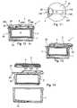
- Figure 1shows a stopper 1 in a first embodiment in a schematic cross-section.
- the stopper 1includes a body element 2 which is intended to close a dispensing opening in a container, the body element 2 having a top face 20 and a bottom face 22, wherein the bottom face 22 is directed towards the inside of the container.
- the body element 2is designed such that it fully closes and/or seals the respective dispensing opening of a container. In other words, if the body element 2 is present in the dispensing opening, it closes the container fully. In particular, it seals the dispensing opening in a moisture tight manner such that the contents inside of the container stay dry when the body element 2 is present.
- a moving element 3is situated on the top face 20 of the body element 2.
- the moving element 3can be moved from the initial position, which is shown in Figure 1 , to an opening position in which the moving element extends beyond the outer dimensions defined by the top face 20 of the body element 2.
- the moving element 3is moved from the initial position to the opening position in a linear fashion. Accordingly, the moving element 3 performs a sliding movement from the initial position to the opening position, and vice versa. Accordingly, the moving element can be regarded a sliding element 3.
- the moving element 3is intended, in the opening position in which it extends beyond at least the outer extension of the top face of the body element, to provide a gripping means for a user to be in a position to remove the body element 2 from the container, such that the product can be dispensed from the container. This will be further exemplified by the description of Figures 8 to 10 below.
- the moving element 3substantially covers the entire top face 20 of the body element 2 in the initial position. Even though it may be appreciated that a small section on the left-hand side of the top face 20 of the body element 2 appears not to be covered by the moving element, the moving element 3 is still considered to cover substantially the entire top face of the body element.
- the small section which is not covered by the moving element 3is attributed to a flattened portion 300 of the moving element 3 which serves, as can be derived from Figures 4 and 5 , to provide a support for a spring element 4 which is, in this embodiment, integrally moulded with the moving element 3.
- the dimensions D3 of the moving element 3 in the plane of the top face 20do not extend beyond the dimensions D2 of the body element 2.
- the moving element 3is provided substantially in the form of a disk, this implies that the diameter of the disk, which corresponds to the outer dimensions D3 of the disk, is equal to or smaller than the diameter of the body element 2, which corresponds to the outer dimension D2.
- the spring element 4is shown to be situated below the moving element 3 and above the top face 20 of the body element 2.
- the spring element 4spring-biases the moving element 3 into the initial position, in which it does not extend beyond the outer dimensions of the body element 2 in the plane of the top face 20.
- the moving element 3If the moving element 3 is moved from its initial position, as shown in Figure 1 , to its opening position, i.e. such that it extends beyond the outer dimension of the top face 20 of the body element 2 in the plane of the top face 20, the spring element 4 pushes the moving element 3 back into its initial position, if released.
- the moving element 3can be moved into direction X from its initial position, as shown in Figure 1 , to the opening position.
- a nose 24is present against which the spring element 4 abuts.
- the nose 24serves as a counter-mount to the spring element 4 such that the spring element 4 can push against the nose 24 in order to move the moving element 3 back into its initial position.
- a tamper-evident member 5 in the form of a tear-off stripis shown which keeps the moving element 3 in its initial position, while being present. In other words, the moving element 3 cannot be moved from the initial position to the opening position while the tamper-evident member 5 is present.
- the tamper-evident member 5extends above the top face 20 of the body element 2 in order to restrict any movement of the moving element 3.
- An overlap between the tear-off strip 5, or any other tamper-evident member, with the container which might be present below the top face 20 of the body element,is, however, not present.
- the tamper-evident member 5 of the present embodimentdoes not have any overlap with a container at all.
- the spring element 4is attached to the moving element 3 at the flattened portion 300 by means of a foil hinge 40.
- Body element 2also includes a desiccant chamber 6 which is situated at the bottom face 22 of the body element 2 and is directed towards the inside of a container.
- the desiccant chamber 6is defined by means of a cylindrical wall 26 which also includes a fastening element 28 which is intended to keep the body element 2 in the closed position in the container.
- Fastening element 28can be, for example, a so called olive which is intended to be in form fit with the inner surface of the container or any other means which provide for a reliable sealing and fitting of the body element 2 in the container.
- Desiccant chamber 6is closed, at the face pointing towards the inside of the container, with a moisture-permeable membrane 60 such that a desiccant material, and/or an oxygen absorber, and/or a gas absorber, which may be present in the desiccant chamber 6, can act to desiccate the volume defined by the container, and/or protect the volume from certain gases, in particular oxygen.
- the entire body element 2can be made from a desiccant material, an oxygen absorber or a gas absorber, or from a polymer which includes a desiccant material, an oxygen absorber or a gas absorber in order to complement and/or support the desiccating and/or gas absorbing function.
- FIG 2is a schematic perspective side view of the body element 2 shown in Figure 1 .
- Body element 2has fastening element 28 provided in the form of the olive around the wall 26, wherein the olive 28 is intended to keep the body element securely and tightly fastened in the dispensing opening of the container.
- Tamper-evident member 5is provided at an edge of the top face 20 of the body element 2. From Figure 2 , it becomes apparent that the tamper-evident member 5 does not extend below the planed defined by the bottom face 22 of the body element 2.
- Figure 3shows the body element 2 and, in particular, the top face 20 of the body element 2 in a schematic top view.
- Nose 24is present, which is used as a counter element for the spring element shown in Figure 1 .
- Rail elements 200which are lifted above the flat surface 20 of the body element 2, are provided.
- the rail elements 200are integrally moulded with the remainder of the body element 2.
- the rail elements 200are intended to provide for a moving connection between the moving element 3 and the body element 2 in the form as schematically shown in Figure 1 .
- Rail elements 200define a space 210 between them, the space being intended to receive the spring element 4 of the moving element 3 as shown in Figure 1 .
- the rail elements 200have, at their side edges 202, undercuts, preferably in the form to establish a dovetail lock, which are intended to receive respective counter-parts of the moving element 3.
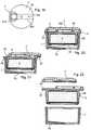
- Figure 4shows the moving element 3 in a bottom view in the arrangement in which it is manufactured.
- Moving element 3is an injection moulded part which includes the spring element 4.
- Moving element 3 and spring element 4are moulded integrally and are connected to one another by means of foil hinge 40 at the flattened portion 300 of the moving element 3.
- the moving element 3includes a recessed section 310 which is recessed with respect to the flat surface 30 of the lower face of the moving element 3.
- the recessed section 310is intended to receive the spring element 4 and provides, at the same time, at its outer edges 302 undercut portions which are complementary to the undercut portions 202 of the body element 2.
- the moving element 3can be moved from the side into the rail portions 200 of the body element 2, such that the moving element 3 can be moved back and forth along the rail elements 200, but cannot be lifted up in a direction perpendicular to the moving direction.
- the moving element 3is injection moulded together with the spring element 4, substantially as a flat element.
- Spring element 4is then folded back into the recessed section 310 of the moving element 3 about the foil hinge 40.
- Spring element 4is then clicked into a clip 304 which extends above the recess section 310 such as to keep the spring element 4 in its active position, as shown in Figure 5 .
- the moving element 3 in this positionnamely with the readily-folded spring element 4, is then moved onto the respective rail portions 200 of the body element 2 from the direction opposite to the position of the tamper-evident member 5 (see Fig. 3 ).
- the moving element 3can then be moved onto the rail portion 200 until the clip 304 of the moving element 3 clicks behind nose 24 such as to maintain the moving element 3 in its initial position and avoid that the moving element is pushed out of connection again by the spring element 4.
- the clip 304 of the moving element 3serves two functions, namely, on the one hand, to keep the spring element 4 in its folded, active position during the process step of moving the moving element 3 along the rail portions 200, and then, after the moving element 3 has been placed onto the top face 20 of the body element 2 and inserted into the respective rail portions 200, the clip 304 prohibits the moving element 3 to move backwards out of its initial position in a direction opposite to the direction towards the tamper-evident element 5.
- the clip 304preferably has a shape as indicated in Figure 1 , namely a shape which is smooth and preferably has an inclination such as to support the moving element 3 when being moved over nose 24 in the direction towards the tamper-evident element 5.
- Clip 304has on the surface opposite to the direction pointing towards the tamper-evident member 5, a sharp and preferably perpendicular surface in order to ensure that the moving element 3 cannot be moved, from its initial position shown in Figure 1 , in a direction opposite to direction X, i.e. out of connection with nose 24.
- Figure 6shows a schematic cross-section through a container 8 in which the stopper 1 is inserted. It becomes apparent that into the container 8 a skirt 7 is inserted, into which the stopper 1 is inserted. Skirt 7 represents, at its upper end 70, the dispensing opening for the products that might be included in the volume 80 of the container.
- Skirt 7is attached to the container 8 by means of a connecting ring 72 which may be glued or pressed into the container 8, or by means of any other suitable mounting technique.
- Skirt 7includes a flow reducer 74, which is intended to reduce the number of products that can be dispensed through the dispensing opening 70 as soon as the stopper 1 is removed from the dispensing opening 70.
- the skirt 7can be made from a desiccant material or from a material which includes a desiccant, and/or an oxygen absorber and/or a gas absorber. Furthermore, in the desiccant chamber 6 of the body element 2 of the stopper 1, a desiccant material can be likewise present.
- the stoppermay include means to regulate the gaseous atmosphere within the volume 80 of the container.
- the meansmay include active substances in the form of the desiccant material, oxygen absorbers or gas absorbers mentioned above, but may also include any sort of absorbers, scavengers, active carbons, means for moisture control, means for oxygen control and the like. These substances may be situated in a hollow space which is defined in the body element 2 and which may be sealed off by a gas permeable membrane.
- fastening elements 28 in the form of the oliveare provided at the body element 2, which can be received in respective counter-part 78 of the skirt 7. Accordingly, a positive lock/form lock of the body element 2 in the skirt 7 can be achieved, such that the dispensing opening 70 of the skirt 7 can be reliably and moisture-tightly sealed.
- Figure 7shows the container 8 in a schematic perspective outer view such that container 8 and stopper 1 can be seen from the outside.
- the body element 2is only shown in the form of a ring which sits on top of the upper edge 82 of the container 8 but which does not at all extend beyond the outer contours of the container 8 in the plane of the top face 20 of the body element 2.
- the presence of the unstructured surface 350 of the moving element 3offers the possibility of easily printing indicia or instructions onto the top surface by different methods, for example by hot-die printing, hot stamping, serigraphy, tampo printing or by using in-mould labelling or engraving in the mould techniques.
- the outer dimensions D3 of the moving element 3 in the plane of the top face 20are equal to or smaller than the outer dimensions D2 of the body element 2 and/or than the outer dimensions D8 of the container 8.
- the outer dimensions D2, D3 and D8substantially correspond to diameters of the respective parts.
- the outer dimensions D2 of the body element 2are also equal to, or smaller than the outer dimensions D8 of the container. This is even more so the case at position 82 where the container 8 connects to the body element 2.
- This specific configurationhas the effect that it is impossible, without the aid of the gripping portion provided by the moving element 3 in the opening position, to grip the body element 2 and open the dispensing opening of the container.
- Moving element 3is placed on top of the top face 20 of the body element 2, wherein the moving element 3 does likewise not extend beyond the outer dimensions of the body element 2, nor of the container 8 in the plane of the top face 20 of the body element 2.
- moving element 3substantially covers the entire top face 20 of the body element 2. In particular, no section of the body element 2 extends beyond the moving element 3 in a direction perpendicular to the plane of the top face 20 of the body element 2. This implies that the moving element 3 is the only element which is present at the top face of the stopper.
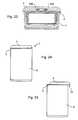
- FIG 8the container 8 and the body element 2 are shown in the closed position.
- the moving element 3is in its initial position and arrow A1 indicates that the tamper-evident member 5 is to be removed in order to start the opening process of the container 8, as the first action.
- Figure 10shows schematically the moving element 3 in its opening position, i.e. in a position in which the moving element 3 extends beyond the dimensions defined by the top face 20 of the body element 2.
- a gripping surface 32is provided by means of a section of the lower face of the moving element 3 which can be used by a user to apply a force in the direction of arrow A3 in order to remove the body element 2 from the dispensing opening of the container 8, as the third action.
- actions A1, A2 and A3are to be carried out, consecutively.
- actions A2 and A3have to be carried out, consecutively.
- the rather complex movements required for opening the containerprovide for improved childproof characteristics.
- Figures 11 to 14show a stopper 1 in a different embodiment, having a different arrangement of the spring element 4.
- Spring element 4has a semi-circular shape, as can be readily appreciated from Figure 11 which shows a bottom view of the moving element 3.
- the spring element 4is, substantially as in the previous embodiment, hinged to the moving element 3 via a foil hinge 40 at the flattened end 300 of the moving element 3.
- a clip 304, guide rails 302 and a recessed portion 310 for receiving the spring element 4are present as in the embodiment discussed with respect to Figures 4 and 5 .
- the spring element 4 of Figure 11is integrally moulded with the remainder of the moving element 3 and is folded about the foil hinge 40 towards the recess 310 of the moving element 3 such that it is situated in the form as shown in Figure 11 .
- Figure 12shows a schematic cross-section through the stopper 1, including the body element 2, the moving element 3 and the skirt 7.
- the moving element 3is in its initial position such that it substantially covers the entire top surface of the stopper.
- the spring element 4abuts against a counter-surface 240 which is present at the top surface 20 of the body element 2.
- FIG 13the stopper 1 of Figure 12 is shown with the moving element 3 moved into the opening position such that a gripping surface 32 becomes available in order to apply a force to the stopper for opening it.
- a gripping surface 32becomes available in order to apply a force to the stopper for opening it.
- the body element 2 together with the moving element 3can be removed from the skirt 7.
- Figure 14shows an exploded view of the arrangement of the moving element 3, the body element 2 and the skirt 7.
- Figures 15 to 18show yet another embodiment of a stopper.
- the layout of moving element 3, body element 2 and skirt 7is substantially the same as that in the previous embodiment such that repeated description thereof will be omitted.
- the spring element 4is, however, in the present embodiment made as a part separate from the moving element 3.
- the spring element 4may be provided in the form of the elastic ring shown in Figure 15 and may be situated in a specifically shaped portion of the recess 310.
- the recess 310in the form as shown in Figure 15 , namely such that it provides support for the ring-shaped spring element 4, the end of the moving element 3 at which the spring element 4 is situated can be fully closed.
- Thishas the advantage that the flattened portion shown at reference numeral 300 in Figure 11 can be avoided. In other words, the covering of the body element 2 by means of the moving element 3 is further improved.
- the ring-shaped spring element 4can be made from a different material than the moving element 3.
- Figure 16shows that the moving element 3 covers, in its initial position, the body element 2 even better than in the previous embodiments.
- the flattened portion 300 was presentis no such portion anymore.
- Figure 17shows the moving element 3 in the opening position, providing a gripping surface 32, and Figure 17 shows an exploded view of the parts.
- a tamper evidence member 5is provided which has to be removed in order to allow for the initial moving movement from the initial position towards the opening position of the moving element 3.
- a spring element 4 in the form of the ring-shaped spring element 4 of the previous embodimentis shown.
- This ring-shaped spring element 4is situated in a portion of the recess 310 of the moving element 3.
- Figure 23shows a cross section through a stopper in a plane perpendicular to the plane of Figures 1 , 12 , 13 , 16 , 17 , 20 and 21 and is intended to clearly but schematically show the rail connection between the moving element 3 and the body element 2.
- the rail elements 202 and 302 of the body element 2 and the moving element 3, respectively,are shown to be provided in an interlocking form.
- the undercuts of the rail elements 202 of the body element 2are in connection with the protuberances of the rail elements 302 of the moving element 3 such that the moving element can be moved in a direction perpendicular to the plane of the cross-section.
- Figure 24is a schematic perspective view on a container 8 with a stopper 1 according to the present disclosure. It becomes apparent that the outer contours of the container with the stopper in its initial position are considerably smooth. In particular, there is no dedicated gripping surface which would enable removing the stopper to open the container 8.
- Figure 25shows the container 8 of Figure 24 with the moving element 3 moved into the opening position. Accordingly, a gripping surface 32 is provided below which the user can grip and lift the stopper in order to access the contents of the container 8.
- stoppers described in the various embodiments aboveare particularly well suited for packaging drugs, in particular drugs which need a controlled gaseous atmosphere in the container in which they are intended to be packaged.
Landscapes
- Engineering & Computer Science (AREA)
- Mechanical Engineering (AREA)
- Manufacturing & Machinery (AREA)
- Closures For Containers (AREA)
Description
- The present invention pertains to a stopper for closing a dispensing opening of a container, the stopper having childproof characteristics.
- Stoppers for closing the dispensing openings of containers are generally known. For containers which are intended to contain powders, granulates, pills, tablets, dragées or any other products in the pharmaceutical or chemical domain, it might be crucial that their respective stoppers cannot be opened or removed by children. This is in particular the case for containers which contain medicine or other substances that can be dangerous when taken in an uncontrolled manner.
- Furthermore, it is often desirable to determine whether the container has already been opened or whether it is in its originally distributed state. In particular, when it comes to the distribution of medicine, it is relevant for the end-user to know whether the container, which contains the medicine, has been tampered with and whether the user can be sure that the medicine contained in the container is original and untouched.
- In order to accommodate for these needs, stoppers are provided which include a tamper-evident member which has to be removed or fractured from the stopper and/or the container before the dispensing opening of the container can be opened for the first time. These tamper-evident members are typically provided in the form of a tear-off ring, a tear-off strip or in the form of foils.
- In order to make sure that the stopper cannot be opened by small children, different techniques and concepts have already been suggested in the prior art. Some of these concepts require that the stopper be opened according to a procedure which requires at least two consecutive complex movements. For example, the user has to push the container in order to gain access to an edge of a stopper which then has to be pushed in a direction perpendicular to the initial pushing direction in order to remove the stopper from the container.
- A different concept is provided in
US 5,299,702 which relates to a stopper for a receptacle. According to this concept, a slide is provided in an upper portion of a stopper, wherein the upper portion of the stopper includes two head sections which project beyond the container and between which the slide is arranged. - In order to open the stopper according to this concept, the slide has to be pushed on its outer circumferential edge in order to provide, at the other side thereof, an edge to lift the stopper and remove it from the dispensing opening.
DE 10 2006 018 449 describes a stopper according to the preamble ofclaim 1 engaging with a ring-shaped neck in a press fit in a container. It has a circular bottom section which seals the container opening, and a head section which rises above the container and encompasses a slide that extends through the center of the head section, the rim of the head section having a maximum diameter that does not exceed the external diameter of the container opening. The stopper is characterized in that the slide can be pushed against the force of a spring in one direction over the rim of the container and, when released, returns to its retracted initial position as a result of the spring resistance. The stopper cannot be removed from the container by small children.- Starting from the prior art mentioned above, it is an object of the present invention to provide a stopper for closing a dispensing opening of a container with improved childproof characteristics and, at the same time, improved handling and design characteristics.
- This objective is solved by a stopper for closing a dispensing opening of a container with all features of
claim 1. - Accordingly, the stopper has a body element for closing the dispensing opening, the body element having a top face and a bottom face, wherein the bottom face is directed towards the inside of the container. A moving element is provided which is situated at the top face of the body element, wherein the moving element is movable relative to the body element from an initial position in which the moving element does not extend beyond the outer extension of the top face in the plane of the top face of the body element, to an opening position in which the moving element is slid relative to the body element to extend at least partly beyond the outer extension of the top face of the body element in the plane of the body element. The moving element provides, in the opening position, a gripping surface for a user to remove the body element from the dispensing opening. The moving element substantially covers the entire top face of the body element in the initial position.
- By the provision of a moving element in the form as stated above, namely that the moving element is situated on the top face of the body element and substantially covers the entire top face of the body element in the initial position, there are several advantages over the known solutions, from a handling perspective, from a childproof perspective as well as from a design perspective. In particular, when viewing the stopper from the top, only the moving element is visible. In particular if the moving element is symmetric it is not obvious that there is a moving element and in which direction it has to be operated.
- From a handling perspective, the user is now free to choose the location where to push the moving element in order to move it from its initial position to the opening position, because the user can touch the moving element in any position on the top surface of the moving element. In the stoppers of the prior art, the user was required to push the slide at a specific position at the edge of the slide, which could be cumbersome to find or to reach, in particular when trying to push it the right position for people with large hands.
- The moving element according to the present disclosure has the advantage that the user has an extended surface, to which he can connect, preferably frictionally, with his fingers in order to move the moving element from the initial position to the opening position. This greatly improves the handling in terms of user friendliness.
- With respect to the childproof aspects of the moving element according to the preset disclosure, it becomes immediately apparent that it is less obvious for a child that the moving element, which represents substantially the entire top face of the stopper, is movable at all. To the young child, the moving element appears to be solitary with the remainder of the container and not movable at all. Furthermore, a specific direction into which the moving element can be moved beyond the outer extension of the body element is not immediately apparent because a defined direction cannot be gathered from the appearance of the top surface of the stopper alone, in particular as the moving element substantially covers the entire top surface. Accordingly, it becomes more difficult for a small child to figure out whether the moving element can be moved at all, and into which direction the moving element can be moved after the child has eventually figured out that the moving element is movable at all.
- The movement of the movable element for moving it between the initial position and the opening position can either be a linear movement, preferably in the form of a sliding movement, or a rotating movement. Naturally, sliding and rotating movements can be combined. In case a sliding movement is chosen, the movable element can also be regarded a sliding element.
- With respect to the design aspects, it will become apparent that the moving element and the body element as described above can be manufactured more easily, in particular by injection moulding, than the stoppers of the prior art. In addition, the stoppers are easier to assemble than the stoppers of the prior art. Accordingly, from a design perspective, the stopper according to the present invention has the advantage that it is easier to produce, manufacture and assemble.
- Preferably, the body element includes a desiccant chamber at its bottom face, in particular directed towards the inside of the container. The provision of a desiccant chamber enables the provision of a desiccant to be filled into the stopper and/or to be inserted into the body element of the stopper in order to desiccate the contents of the container. The body element of the stopper may include a bottom face defining a hollow space into which an active substance can be filled which is intended to regulate the gaseous atmosphere inside of the volume of the container.
- The body element can also be made at least partly from a desiccant material, and/or an oxygen absorber and/or a gas absorber, in particular from a resin including a desiccant, and/or an oxygen absorber and/or a gas absorber. The advantage of this embodiment is that the contents of the container can be desiccated or protected from gases by means of the body element of the stopper.
- The stopper may include means to regulate the gaseous atmosphere within the container. The means may include active substances in the form of the desiccant material, oxygen absorbers or gas absorbers mentioned above, but may also include any sort of absorbers, scavengers, active carbons, means for moisture control, means for oxygen control and the like.
- It is apparent that the stopper defined above is particularly well suited for packaging drugs, in particular drugs which need a controlled gaseous atmosphere in the container in which they are intended to be packaged.
- The top face of the body element may have dimensions smaller than, or equal to, the outer dimensions of the container in a plane of the top face of the body element. Furthermore, the moving element may have dimensions smaller than or equal to the dimensions of the top face of the body element in the plane of the top face of the body element and/or to the container at a position in which the body element is connected to the container. This has the advantage that in the initial position of the moving element, no edges are present which could be used to lift off the stopper from the dispensing opening. Accordingly, it is impossible to remove the stopper from the dispensing opening such that the childproof feature is even improved.
- In other words, the moving element, the top face of the body element and the outer dimensions of the container in the plane of the top face provide a smooth transition between the respective parts, making it impossible to grip the moving element or the body element to open the dispensing opening. The outer dimensions of the top face and, subsequently, the outer dimensions of the moving element in the plane of the top face can also be smaller than the outer dimensions of the container in the plane of the top face. In case the outer dimensions of the moving element are smaller than the outer dimensions of the container, it is even more assured that a user cannot open the stopper without moving the moving element from the initial position into the opening position. It is important, however, that the outer dimensions of the moving element do not extend beyond the outer extensions of the top face of the body element and/or the outer extension of the container at the section at which the stopper connects to the container, in the plane of the top face of the body element.
- The moving element may be mounted to the top face of the body element by means of a positive locking rail element, in particular by means of a dovetail positive lock, to allow for the movement of the moving element from the initial position to the opening position. In this respect, the moving element may be mounted to the body element by mounting means situated at the bottom face of the moving element only. By means of the provision of a positive locking fit between the moving element and the body element, it can be made sure that the moving element and the body element are securely fastened to one another, despite being movable. In particular, it becomes possible transferring a force from the moving element in its opening position onto the body element, in order to be in a position to remove the body element from the container.
- The body element may be shaped such that it does not extend beyond the plane defined by the moving element in a direction perpendicular to the plane defined by the moving element. In other words, at the end face of the stopper only the moving element is present. This improves the childproof function even more because it camouflages the fact that the moving element is actually movable.
- The moving element may be spring-biased with respect to the body element towards the initial position such that the moving element always returns to the initial position even after having been displaced into the opening position.
- The moving element may include a spring element which is integrally moulded with the moving element. The spring element might be moulded in the same plane as the moving element and be hinged to the moving element by means of a foil hinge. By the provision of the spring element integrally moulded to the moving element, a very reliable connection between the spring element and the moving element can be achieved. When the moving element and the spring element are moulded in the same plane, the moulding process as such can be very simple and effective because the mould as such can be made as a relatively simple one-layered mould.
- The spring element may be integrated with the moving element by means of a foil hinge such that it can be folded into the working position by pivoting the spring element from its manufactured position into its active position by tilting it by 180°, such as to be adjacent to the bottom face of the moving element.
- In an alternative embodiment, the spring element may be provided separate from the moving element and the spring element is associated with the moving element, preferably situated in a recess of the moving element. Preferably, the spring element is made from a material different than that of the moving element. This has the advantage that the spring element can be made from a material which is suitable for the spring action of the spring element and the moving element can be manufactured from a more economical material. Furthermore, the provision of the separate spring element obviates the need for the step of folding the spring element below the moving element such that one relatively complex process step can be avoided.
- To movably connect the moving element with the body element, the moving element may include a recessed portion including a positive locking element. This recess may be dimensioned to receive the spring element in order to provide for a compact arrangement.
- To further improve the manufacturing characteristics, a clip element may be provided in the recess which is intended to maintain the spring element in its active position.
- A clip element may be provided which is intended to block the movement of the moving element in one direction such as to make sure that the moving element does not fall off the body element, once assembled.
- A skirt may be present which is to be inserted into the container to define the dispensing opening, the body element being insertable into the skirt in order to close the dispensing opening. This skirt may include a flow reducer to reduce the flow of products to be dispensed through the dispensing opening. The skirt and/or the flow reducer may be made from a material including a desiccant, and/or an oxygen absorber and/or a gas absorber, in particular a resin including a desiccant, and/or an oxygen absorber, and/or a gas absorber.
- In order to provide for tamper-evidence, a tamper-evident member may be provided to prohibit the movement of the moving element from the initial position to the opening position, wherein the tamper-evident member is removable by a user. The tamper-evident member may extend above the top face of the body element and is integrally moulded with the body element.
- The body element may be hinged to the container by means of a foil hinge, preferably hinged to the skirt. The body element may be attached to the container or the skirt by means of a positive locking, a press-fit or any other suitable locking mechanism.
- Preferably, the top surface of the moving element is provided with a hot-die print, a hot stamp print, a serigraphy, a tampo print and/or an in-mould print. By means of the provision of the print on the top surface of the moving element, the moving element is designed such as to allow a decoration which may be intended to provide information about the use of the container, in particular instructions for opening the container, and/or information with respect to the drug contained in the container, for example its brand name.
- Designing a moving element in the form as claimed allows a maximum of the surface of the moving element to be available as the decoration/printing surface.
- Further features and advantages of the invention will become clear from the following detailed description of the Figures in which:
- Figure 1
- is a cross-sectional view of a stopper with a moving element and a body element, a desiccant chamber and a tamper-evident member;
- Figure 2
- is a perspective side view of the body element of the stopper according to
Figure 1 ; - Figure 3
- is a top view of the body element of
Figure 2 ; - Figure 4
- is a bottom view of the moving element with a spring element in its manufactured position;
- Figure 5
- shows the moving element of
Figure 4 with the spring element arranged in its active position; - Figure 6
- shows a container with the stopper and a skirt in a schematic cross-sectional view;
- Figure 7
- shows the container with the stopper in a perspective side view;
- Figure 8
- shows the container in a perspective side view, with the moving element in its initial position and the tamper-evidence member in place;
- Figure 9
- shows the container of
Figure 8 in a perspective side view with the tamperevident member removed; - Figure 10
- shows the container of
Figures 8 and 9 in a configuration in which the moving element is moved into the opening position; - Figures 11 to
- cshow a stopper in another embodiment, having a semi-circular spring element hinged to the moving element;
- Figures 15 to 18
- show a stopper in yet another embodiment with a spring element inserted into a receiving portion, the stopper having a tamper-evidence member;
- Figures 19 to 22
- show a stopper in yet another embodiment with a spring element inserted into a receiving portion but without a tamper-evidence member;
- Figure 23 is a
- schematic cross-section through a stopper in a plane perpendicular to the moving plane, showing an embodiment of positive locking rail elements;
- Figure 24
- is a schematic perspective view of a container with a stopper according to the present disclosure, the stopper having a moving element covering the entire top face of the body element and the skirt, the moving element being in its initial position;
- Figure 25
- is a schematic perspective view of the container of
Figure 24 with the moving element in the opening position. - In the following, the disclosure will be explained in more detail by reference to the drawings of the Figures. In the Figures, same reference numerals are used to indicate like elements or like functional entities and repeated description thereof may be omitted in order to reduce redundancies.
Figure 1 shows astopper 1 in a first embodiment in a schematic cross-section. Thestopper 1 includes abody element 2 which is intended to close a dispensing opening in a container, thebody element 2 having atop face 20 and abottom face 22, wherein thebottom face 22 is directed towards the inside of the container.- Typically, the
body element 2 is designed such that it fully closes and/or seals the respective dispensing opening of a container. In other words, if thebody element 2 is present in the dispensing opening, it closes the container fully. In particular, it seals the dispensing opening in a moisture tight manner such that the contents inside of the container stay dry when thebody element 2 is present. - A moving
element 3 is situated on thetop face 20 of thebody element 2. The movingelement 3 can be moved from the initial position, which is shown inFigure 1 , to an opening position in which the moving element extends beyond the outer dimensions defined by thetop face 20 of thebody element 2. In the embodiments shown herein, the movingelement 3 is moved from the initial position to the opening position in a linear fashion. Accordingly, the movingelement 3 performs a sliding movement from the initial position to the opening position, and vice versa. Accordingly, the moving element can be regarded a slidingelement 3. - The moving
element 3 is intended, in the opening position in which it extends beyond at least the outer extension of the top face of the body element, to provide a gripping means for a user to be in a position to remove thebody element 2 from the container, such that the product can be dispensed from the container. This will be further exemplified by the description ofFigures 8 to 10 below. - The moving
element 3 substantially covers the entiretop face 20 of thebody element 2 in the initial position. Even though it may be appreciated that a small section on the left-hand side of thetop face 20 of thebody element 2 appears not to be covered by the moving element, the movingelement 3 is still considered to cover substantially the entire top face of the body element. The small section which is not covered by the movingelement 3 is attributed to a flattenedportion 300 of the movingelement 3 which serves, as can be derived fromFigures 4 and 5 , to provide a support for aspring element 4 which is, in this embodiment, integrally moulded with the movingelement 3. - In particular, the dimensions D3 of the moving
element 3 in the plane of thetop face 20 do not extend beyond the dimensions D2 of thebody element 2. In case the movingelement 3 is provided substantially in the form of a disk, this implies that the diameter of the disk, which corresponds to the outer dimensions D3 of the disk, is equal to or smaller than the diameter of thebody element 2, which corresponds to the outer dimension D2. - In
Figure 1 , thespring element 4 is shown to be situated below the movingelement 3 and above thetop face 20 of thebody element 2. Thespring element 4 spring-biases the movingelement 3 into the initial position, in which it does not extend beyond the outer dimensions of thebody element 2 in the plane of thetop face 20. - If the moving
element 3 is moved from its initial position, as shown inFigure 1 , to its opening position, i.e. such that it extends beyond the outer dimension of thetop face 20 of thebody element 2 in the plane of thetop face 20, thespring element 4 pushes the movingelement 3 back into its initial position, if released. - The moving
element 3 can be moved into direction X from its initial position, as shown inFigure 1 , to the opening position. At thetop face 20 of the bottom element, anose 24 is present against which thespring element 4 abuts. Thenose 24 serves as a counter-mount to thespring element 4 such that thespring element 4 can push against thenose 24 in order to move the movingelement 3 back into its initial position. - In
Figure 1 , a tamper-evident member 5 in the form of a tear-off strip is shown which keeps the movingelement 3 in its initial position, while being present. In other words, the movingelement 3 cannot be moved from the initial position to the opening position while the tamper-evident member 5 is present. - The tamper-
evident member 5 extends above thetop face 20 of thebody element 2 in order to restrict any movement of the movingelement 3. An overlap between the tear-off strip 5, or any other tamper-evident member, with the container which might be present below thetop face 20 of the body element, is, however, not present. In particular, the tamper-evident member 5 of the present embodiment does not have any overlap with a container at all. - The
spring element 4 is attached to the movingelement 3 at the flattenedportion 300 by means of afoil hinge 40. Body element 2 also includes adesiccant chamber 6 which is situated at thebottom face 22 of thebody element 2 and is directed towards the inside of a container. Thedesiccant chamber 6 is defined by means of acylindrical wall 26 which also includes afastening element 28 which is intended to keep thebody element 2 in the closed position in the container. Fasteningelement 28 can be, for example, a so called olive which is intended to be in form fit with the inner surface of the container or any other means which provide for a reliable sealing and fitting of thebody element 2 in the container.Desiccant chamber 6 is closed, at the face pointing towards the inside of the container, with a moisture-permeable membrane 60 such that a desiccant material, and/or an oxygen absorber, and/or a gas absorber, which may be present in thedesiccant chamber 6, can act to desiccate the volume defined by the container, and/or protect the volume from certain gases, in particular oxygen.- As an alternative or as a supplement to the
desiccant chamber 6, theentire body element 2 can be made from a desiccant material, an oxygen absorber or a gas absorber, or from a polymer which includes a desiccant material, an oxygen absorber or a gas absorber in order to complement and/or support the desiccating and/or gas absorbing function. Figure 2 is a schematic perspective side view of thebody element 2 shown inFigure 1 .Body element 2 hasfastening element 28 provided in the form of the olive around thewall 26, wherein the olive 28 is intended to keep the body element securely and tightly fastened in the dispensing opening of the container.- Tamper-
evident member 5 is provided at an edge of thetop face 20 of thebody element 2. FromFigure 2 , it becomes apparent that the tamper-evident member 5 does not extend below the planed defined by thebottom face 22 of thebody element 2. Figure 3 shows thebody element 2 and, in particular, thetop face 20 of thebody element 2 in a schematic top view.Nose 24 is present, which is used as a counter element for the spring element shown inFigure 1 .Rail elements 200, which are lifted above theflat surface 20 of thebody element 2, are provided. Therail elements 200 are integrally moulded with the remainder of thebody element 2. Therail elements 200 are intended to provide for a moving connection between the movingelement 3 and thebody element 2 in the form as schematically shown inFigure 1 .Rail elements 200 define aspace 210 between them, the space being intended to receive thespring element 4 of the movingelement 3 as shown inFigure 1 . Therail elements 200 have, at theirside edges 202, undercuts, preferably in the form to establish a dovetail lock, which are intended to receive respective counter-parts of the movingelement 3.Figure 4 shows the movingelement 3 in a bottom view in the arrangement in which it is manufactured. Movingelement 3 is an injection moulded part which includes thespring element 4. Movingelement 3 andspring element 4 are moulded integrally and are connected to one another by means of foil hinge 40 at the flattenedportion 300 of the movingelement 3.- The moving
element 3 includes a recessedsection 310 which is recessed with respect to theflat surface 30 of the lower face of the movingelement 3. The recessedsection 310 is intended to receive thespring element 4 and provides, at the same time, at itsouter edges 302 undercut portions which are complementary to theundercut portions 202 of thebody element 2. In other words, the movingelement 3 can be moved from the side into therail portions 200 of thebody element 2, such that the movingelement 3 can be moved back and forth along therail elements 200, but cannot be lifted up in a direction perpendicular to the moving direction. - With respect to the actual manufacturing process of the moving
element 3, the movingelement 3 is injection moulded together with thespring element 4, substantially as a flat element.Spring element 4 is then folded back into the recessedsection 310 of the movingelement 3 about thefoil hinge 40.Spring element 4 is then clicked into aclip 304 which extends above therecess section 310 such as to keep thespring element 4 in its active position, as shown inFigure 5 . - The moving
element 3 in this position, namely with the readily-foldedspring element 4, is then moved onto therespective rail portions 200 of thebody element 2 from the direction opposite to the position of the tamper-evident member 5 (seeFig. 3 ). The movingelement 3 can then be moved onto therail portion 200 until theclip 304 of the movingelement 3 clicks behindnose 24 such as to maintain the movingelement 3 in its initial position and avoid that the moving element is pushed out of connection again by thespring element 4. - In other words, the
clip 304 of the movingelement 3 serves two functions, namely, on the one hand, to keep thespring element 4 in its folded, active position during the process step of moving the movingelement 3 along therail portions 200, and then, after the movingelement 3 has been placed onto thetop face 20 of thebody element 2 and inserted into therespective rail portions 200, theclip 304 prohibits the movingelement 3 to move backwards out of its initial position in a direction opposite to the direction towards the tamper-evident element 5. - To this end, the
clip 304 preferably has a shape as indicated inFigure 1 , namely a shape which is smooth and preferably has an inclination such as to support the movingelement 3 when being moved overnose 24 in the direction towards the tamper-evident element 5.Clip 304 has on the surface opposite to the direction pointing towards the tamper-evident member 5, a sharp and preferably perpendicular surface in order to ensure that the movingelement 3 cannot be moved, from its initial position shown inFigure 1 , in a direction opposite to direction X, i.e. out of connection withnose 24. Figure 6 shows a schematic cross-section through acontainer 8 in which thestopper 1 is inserted. It becomes apparent that into the container 8 askirt 7 is inserted, into which thestopper 1 is inserted.Skirt 7 represents, at itsupper end 70, the dispensing opening for the products that might be included in thevolume 80 of the container.Skirt 7 is attached to thecontainer 8 by means of a connectingring 72 which may be glued or pressed into thecontainer 8, or by means of any other suitable mounting technique.Skirt 7 includes aflow reducer 74, which is intended to reduce the number of products that can be dispensed through the dispensingopening 70 as soon as thestopper 1 is removed from the dispensingopening 70.- To provide an efficient desiccation of the
volume 80 of thecontainer 8, theskirt 7 can be made from a desiccant material or from a material which includes a desiccant, and/or an oxygen absorber and/or a gas absorber. Furthermore, in thedesiccant chamber 6 of thebody element 2 of thestopper 1, a desiccant material can be likewise present. - In the embodiments described herein, the stopper may include means to regulate the gaseous atmosphere within the
volume 80 of the container. The means may include active substances in the form of the desiccant material, oxygen absorbers or gas absorbers mentioned above, but may also include any sort of absorbers, scavengers, active carbons, means for moisture control, means for oxygen control and the like. These substances may be situated in a hollow space which is defined in thebody element 2 and which may be sealed off by a gas permeable membrane. - In order to attach the
body element 2 to theskirt 7,fastening elements 28 in the form of the olive are provided at thebody element 2, which can be received inrespective counter-part 78 of theskirt 7. Accordingly, a positive lock/form lock of thebody element 2 in theskirt 7 can be achieved, such that the dispensingopening 70 of theskirt 7 can be reliably and moisture-tightly sealed. Figure 7 shows thecontainer 8 in a schematic perspective outer view such thatcontainer 8 andstopper 1 can be seen from the outside. As to thestopper 1, thebody element 2 is only shown in the form of a ring which sits on top of theupper edge 82 of thecontainer 8 but which does not at all extend beyond the outer contours of thecontainer 8 in the plane of thetop face 20 of thebody element 2.- The presence of the
unstructured surface 350 of the movingelement 3 offers the possibility of easily printing indicia or instructions onto the top surface by different methods, for example by hot-die printing, hot stamping, serigraphy, tampo printing or by using in-mould labelling or engraving in the mould techniques. - From
Figure 7 it also becomes apparent that the outer dimensions D3 of the movingelement 3 in the plane of thetop face 20 are equal to or smaller than the outer dimensions D2 of thebody element 2 and/or than the outer dimensions D8 of thecontainer 8. For acylindrical container 8, the outer dimensions D2, D3 and D8 substantially correspond to diameters of the respective parts. - It has to be observed that the outer dimensions D2 of the
body element 2 are also equal to, or smaller than the outer dimensions D8 of the container. This is even more so the case atposition 82 where thecontainer 8 connects to thebody element 2. This specific configuration has the effect that it is impossible, without the aid of the gripping portion provided by the movingelement 3 in the opening position, to grip thebody element 2 and open the dispensing opening of the container. - Moving
element 3 is placed on top of thetop face 20 of thebody element 2, wherein the movingelement 3 does likewise not extend beyond the outer dimensions of thebody element 2, nor of thecontainer 8 in the plane of thetop face 20 of thebody element 2. - As can be easily appreciated from
Figure 7 , movingelement 3 substantially covers the entiretop face 20 of thebody element 2. In particular, no section of thebody element 2 extends beyond the movingelement 3 in a direction perpendicular to the plane of thetop face 20 of thebody element 2. This implies that the movingelement 3 is the only element which is present at the top face of the stopper. - In order to open the dispensing opening of the
container 8, first of all the tamper-evident member 5 needs to be removed and then the movingelement 3 be moved from its initial position, as shown inFigure 4 , towards its opening position in which it provides for a gripping means to remove the body element from the dispensing opening. - The process for opening the container is shown, schematically, in
Figures 8 to 10 . - In
Figure 8 , thecontainer 8 and thebody element 2 are shown in the closed position. The movingelement 3 is in its initial position and arrow A1 indicates that the tamper-evident member 5 is to be removed in order to start the opening process of thecontainer 8, as the first action. - In
Figure 9 , the tamper-evident member is already removed and arrow A2 indicates that the movingelement 3 is to be moved into the direction in which the tamper-evident element 5 used to be present, in order to move the movingelement 3 from its initial position into its opening position, as the second action. Figure 10 shows schematically the movingelement 3 in its opening position, i.e. in a position in which the movingelement 3 extends beyond the dimensions defined by thetop face 20 of thebody element 2. A grippingsurface 32 is provided by means of a section of the lower face of the movingelement 3 which can be used by a user to apply a force in the direction of arrow A3 in order to remove thebody element 2 from the dispensing opening of thecontainer 8, as the third action.- Accordingly, in order to open the dispensing opening of the
container 8 for the first time, actions A1, A2 and A3 are to be carried out, consecutively. After thecontainer 8 has been opened for the first time, actions A2 and A3 have to be carried out, consecutively. The rather complex movements required for opening the container provide for improved childproof characteristics. Figures 11 to 14 show astopper 1 in a different embodiment, having a different arrangement of thespring element 4.Spring element 4 has a semi-circular shape, as can be readily appreciated fromFigure 11 which shows a bottom view of the movingelement 3. Thespring element 4 is, substantially as in the previous embodiment, hinged to the movingelement 3 via afoil hinge 40 at the flattenedend 300 of the movingelement 3.- A
clip 304,guide rails 302 and a recessedportion 310 for receiving thespring element 4 are present as in the embodiment discussed with respect toFigures 4 and 5 . - The
spring element 4 ofFigure 11 is integrally moulded with the remainder of the movingelement 3 and is folded about thefoil hinge 40 towards therecess 310 of the movingelement 3 such that it is situated in the form as shown inFigure 11 . Figure 12 shows a schematic cross-section through thestopper 1, including thebody element 2, the movingelement 3 and theskirt 7. In this Figure, the movingelement 3 is in its initial position such that it substantially covers the entire top surface of the stopper. Thespring element 4 abuts against a counter-surface 240 which is present at thetop surface 20 of thebody element 2.- In
Figure 13 , thestopper 1 ofFigure 12 is shown with the movingelement 3 moved into the opening position such that agripping surface 32 becomes available in order to apply a force to the stopper for opening it. In particular, by applying a force to thegripping surface 32 thebody element 2 together with the movingelement 3 can be removed from theskirt 7. Figure 14 shows an exploded view of the arrangement of the movingelement 3, thebody element 2 and theskirt 7.Figures 15 to 18 show yet another embodiment of a stopper. The layout of movingelement 3,body element 2 andskirt 7 is substantially the same as that in the previous embodiment such that repeated description thereof will be omitted.- The
spring element 4 is, however, in the present embodiment made as a part separate from the movingelement 3. Thespring element 4 may be provided in the form of the elastic ring shown inFigure 15 and may be situated in a specifically shaped portion of therecess 310. By the provision of therecess 310 in the form as shown inFigure 15 , namely such that it provides support for the ring-shapedspring element 4, the end of the movingelement 3 at which thespring element 4 is situated can be fully closed. This has the advantage that the flattened portion shown atreference numeral 300 inFigure 11 can be avoided. In other words, the covering of thebody element 2 by means of the movingelement 3 is further improved. - The ring-shaped
spring element 4 can be made from a different material than the movingelement 3. Figure 16 shows that the movingelement 3 covers, in its initial position, thebody element 2 even better than in the previous embodiments. In particular, at the left hand side in which in the previous embodiments the flattenedportion 300 was present, is no such portion anymore.Figure 17 shows the movingelement 3 in the opening position, providing agripping surface 32, andFigure 17 shows an exploded view of the parts.- In this embodiment, a
tamper evidence member 5 is provided which has to be removed in order to allow for the initial moving movement from the initial position towards the opening position of the movingelement 3. - In the embodiment shown in
Figures 19 to 22 , aspring element 4 in the form of the ring-shapedspring element 4 of the previous embodiment is shown. This ring-shapedspring element 4 is situated in a portion of therecess 310 of the movingelement 3. - The difference between the previous embodiment and the present embodiment is that no tamper evidence member is provided.
Figure 23 shows a cross section through a stopper in a plane perpendicular to the plane ofFigures 1 ,12 ,13 ,16 ,17 ,20 and 21 and is intended to clearly but schematically show the rail connection between the movingelement 3 and thebody element 2. In particular, therail elements body element 2 and the movingelement 3, respectively, are shown to be provided in an interlocking form. The undercuts of therail elements 202 of thebody element 2 are in connection with the protuberances of therail elements 302 of the movingelement 3 such that the moving element can be moved in a direction perpendicular to the plane of the cross-section.Figure 24 is a schematic perspective view on acontainer 8 with astopper 1 according to the present disclosure. It becomes apparent that the outer contours of the container with the stopper in its initial position are considerably smooth. In particular, there is no dedicated gripping surface which would enable removing the stopper to open thecontainer 8.Figure 25 shows thecontainer 8 ofFigure 24 with the movingelement 3 moved into the opening position. Accordingly, a grippingsurface 32 is provided below which the user can grip and lift the stopper in order to access the contents of thecontainer 8.- The stoppers described in the various embodiments above are particularly well suited for packaging drugs, in particular drugs which need a controlled gaseous atmosphere in the container in which they are intended to be packaged.
Claims (14)
- Stopper (1) for closing a dispensing opening (70) of a container (8), the stopper (1) comprising:a body element (2) for closing the dispensing opening (70), the body element (2) having a top face (20) and a bottom face (22), the bottom face (22) being directed towards the inside of the container (8);a moving element (3) which is situated at the top face (20) of the body element (2),
wherein the moving element (3) is movable relative to the body element (2) from an initial position in which the moving element (3) does not extend beyond the outer extension of the top face (20) in the plane of the top face (20) of the body element (3), to an opening position in which the moving element (3) is moved relative to the body element (1) to extend at least partly beyond the outer extension of the top face (20) of the body element (2) in the plane of the body element (2), wherein
the moving element (3) provides in the opening position, a gripping surface (32) for a user to remove the body element (2) from the dispensing opening (70),
characterized in that
the moving element (3) substantially covers the entire top face (20) of the body element (2) in the initial position. - Stopper (1) according to claim 1, wherein the body element (2) includes a desiccant chamber (6) situated at the bottom face of the body element, and/or wherein the body element is made at least partly from a desiccant material, and/or an oxygen absorber and/or a gas absorber, and is, in particular, made from a resin including a desiccant material, and/or an oxygen absorber and/or a gas absorber.
- Stopper (1) according to any one of the preceding claims, wherein the top face (20) of the body element (2) has dimensions smaller than, or equal to, the outer dimensions of the container in a plane of the top face of the body element and/or wherein the moving element (3) has dimensions smaller than or equal to the dimensions of the top face of the body element in the plane of the top face (20) of the body element (2) and/or to the container (8) at a position in which the body element is connected to the container and/or wherein the body element (2) does not extend beyond the plane defined by the moving element in a direction perpendicular to the plane defined by the moving element (3).
- Stopper (1) according to any one of the preceding claims, wherein the moving element (3) is mounted to the top face (20) of the body element (2) by means of a positive locking rail element (202, 302), in particular by means of a dovetail positive lock, to allow for the moving movement of the moving element from the initial position to the opening position and/or wherein the moving element is mounted to the body element by mounting means (302) situated at the bottom face of the moving element (3) only.
- Stopper (1) according to any one of the preceding claims, wherein the moving element (3) is spring-biased towards the initial position, preferably wherein the moving element includes a spring element (4) which is integrally moulded with the moving element, preferably wherein the spring element (4) is injection moulded in the same plane as the moving element and is hinged to the moving element (3), preferably via a foil hinge (40).
- Stopper (1) according to any one of claims 1 to 4, wherein the moving element (3) is spring-biased towards the initial position, preferably wherein a separate spring element (4) is associated with the moving element, preferably situated in a recess (310) of the moving element, preferably wherein the spring element is made from a material different than that of the moving element (3).
- Stopper (1) according to any one of the preceding claims, wherein the moving element (3) includes a recess (310) including a positive locking rail element (302) to movably connect the moving element with the body element (2), preferably wherein the recess (310) is dimensioned to receive a spring element (4), more preferably wherein in the recess (310) a clip element (304) is provided, which is intended to maintain the spring element (4) in its active position, more preferably wherein in the recess (310) a clip element (304) is provided which is intended to block the moving movement of the moving element (3) in one direction.
- Stopper (1) according to any one of the preceding claims, wherein a tamper-evident member (5) is provided to prohibit the movement of the moving element (3) from the initial position to the opening position, wherein the tamper-evident member (5) is removable by a user, preferably wherein the tamper-evident member extends above the top face (20) of the body element (2) and is integrally moulded with the body element (2).
- Stopper (1) according to any one of the preceding claims, wherein the stopper further includes a skirt (7) which is to be inserted into the container (8) to define the dispensing opening (70), the body element (2) being msertable into the skirt (7) in order to close the dispensing opening (70), preferably wherein the skirt (7) includes a flow reducer (74) to reduce the flow of products to be dispensed through the dispensing opening, more preferably wherein the skirt (7) contains a desiccant material, and/or an oxygen absorber and/or a gas absorber, in particular wherein the skirt is made from a resin including a desiccant material, and/or an oxygen absorber and/or a gas absorber.
- Stopper (1) according to any one of the preceding claims, wherein the body element (2) is hinged to the container (8) by means of a foil hinge, preferably hinged to the skirt (7).
- Stopper (1) according to any one of the preceding claims, wherein the top surface of the moving element (3) is provided with a hot-die print, a hot stamp print, a serigraphy, a tampo print, an in-mould print and/or engraving of the mold.
- Stopper (1) according to any one of the preceding claims, wherein the moving element (3) is movable linearly from the initial position into the opening position, preferably in a sliding movement.
- Stopper (1) according to any one of the preceding claims, wherein the moving element (3) is movable rotationally from the initial position to the opening position.
- Method for manufacturing a stopper (1) according to any of the preceding claims, including the steps of:moulding a moving element (3) including a spring element (4), the spring element (4) being moulded in the plane of the moving elemenf (3);folding the spring element (4) below the moving element (3);mounting the moving element (3) to a body element (2).
Priority Applications (3)
| Application Number | Priority Date | Filing Date | Title |
|---|---|---|---|
| EP10305608.1AEP2394926B1 (en) | 2010-06-08 | 2010-06-08 | Child safe stopper |
| US13/098,545US8875919B2 (en) | 2010-06-08 | 2011-05-02 | Stopper for closing a dispensing opening of a container |
| US14/526,877US9573734B2 (en) | 2010-06-08 | 2014-10-29 | Stopper for closing a dispensing opening of a container |
Applications Claiming Priority (1)
| Application Number | Priority Date | Filing Date | Title |
|---|---|---|---|
| EP10305608.1AEP2394926B1 (en) | 2010-06-08 | 2010-06-08 | Child safe stopper |
Publications (2)
| Publication Number | Publication Date |
|---|---|
| EP2394926A1 EP2394926A1 (en) | 2011-12-14 |
| EP2394926B1true EP2394926B1 (en) | 2015-01-07 |
Family
ID=42480767
Family Applications (1)
| Application Number | Title | Priority Date | Filing Date |
|---|---|---|---|
| EP10305608.1AActiveEP2394926B1 (en) | 2010-06-08 | 2010-06-08 | Child safe stopper |
Country Status (2)
| Country | Link |
|---|---|
| US (1) | US8875919B2 (en) |
| EP (1) | EP2394926B1 (en) |
Families Citing this family (8)
| Publication number | Priority date | Publication date | Assignee | Title |
|---|---|---|---|---|
| USD798720S1 (en) | 2013-10-31 | 2017-10-03 | Clariant Production (France) Sas | Container |
| US20150197363A1 (en)* | 2014-01-15 | 2015-07-16 | Ellery West | Biodegradable container having a child resistant closure |
| US20150259115A1 (en)* | 2014-03-12 | 2015-09-17 | Huan-Fu Yeh | Sealed Container with Moisture-proof Function |
| TWD172808S (en)* | 2014-11-27 | 2016-01-01 | Clariant Production France Sas | Container |
| DE102016009483B4 (en)* | 2016-08-05 | 2019-01-10 | Gaplast Gmbh | Container closure system |
| CN217436532U (en)* | 2020-12-30 | 2022-09-16 | 艾尔诺沃股份有限公司 | Dispensing device for storing and dispensing unit products |
| EP4209429B1 (en)* | 2021-12-30 | 2025-08-27 | Airnov, Inc. | Dispensing device |
| EP4205831A1 (en)* | 2021-12-31 | 2023-07-05 | Airnov, Inc. | Gas-permeable and liquid-tight receptacle for an active substance |
Family Cites Families (46)
| Publication number | Priority date | Publication date | Assignee | Title |
|---|---|---|---|---|
| US2173046A (en) | 1938-10-15 | 1939-09-12 | Harry T Smith | Saltcellar |
| GB539891A (en) | 1940-11-15 | 1941-09-26 | Cascelloid Ltd | Improvements in stoppers for containers |
| FR892608A (en) | 1943-03-19 | 1944-05-15 | Capping device | |
| US2766796A (en)* | 1953-01-12 | 1956-10-16 | Earl S Tupper | Vacuum and seal type of receptacle |
| US2918167A (en) | 1957-12-19 | 1959-12-22 | Lowen Stanley | Pill or tablet dispenser |
| GB1074165A (en) | 1965-06-01 | 1965-06-28 | Sure Form Plastics Ltd | Improvements in and relating to shives for casks and kegs |
| US3435988A (en) | 1968-03-20 | 1969-04-01 | Sobel Ind Inc | Paper cup dispenser |
| US3517855A (en) | 1968-06-17 | 1970-06-30 | Man Mark Projects Ltd | Desk paper dispenser |
| US3581934A (en) | 1969-05-01 | 1971-06-01 | American Can Co | Adjustable cup dispenser |
| US3625386A (en)* | 1969-11-25 | 1971-12-07 | Res & Safety Devices Corp | Safety container assembly |
| US3792803A (en)* | 1972-11-20 | 1974-02-19 | G Kessler | Self-reclosing cap for containers |
| US3921851A (en) | 1974-02-25 | 1975-11-25 | Billy N Nilson | Disabling device for dispenser for tablets |
| GB1594132A (en) | 1977-08-15 | 1981-07-30 | Johnsen Jorgensen Plastics Ltd | Dispensing containers |
| CA1121320A (en) | 1978-05-31 | 1982-04-06 | William Marykuca | Welding electrode dispenser |
| US4240564A (en) | 1979-02-22 | 1980-12-23 | Pritchard William F | Soap leaf dispenser |
| EP0095544A1 (en)* | 1982-05-27 | 1983-12-07 | Geiger Plastic GmbH | Tamperproof closure for containers |
| DE3632546A1 (en) | 1986-09-25 | 1988-03-31 | Knoll Ag | DOSAGE DISPENSER |
| DE3715938A1 (en)* | 1987-05-13 | 1988-11-24 | Boehringer Mannheim Gmbh | CONTAINER FOR TEST STRIP |
| GB2210603A (en) | 1987-10-02 | 1989-06-14 | Philip Nigel Record | Card dispenser |
| FR2624106A1 (en) | 1987-12-07 | 1989-06-09 | Platex | Box for packaging and dispensing cotton buds |
| ES2144461T3 (en) | 1990-05-02 | 2000-06-16 | Grace W R & Co | POLYMER COMPOSITIONS CONTAINING OXYGEN SENSING COMPOUNDS. |
| JPH0515455A (en) | 1991-07-09 | 1993-01-26 | Matsushita Electric Ind Co Ltd | Water heater |
| DE4134082C2 (en) | 1991-10-15 | 1993-12-23 | Gaplast Gmbh | Stopper for a container |
| US5285917A (en)* | 1992-03-11 | 1994-02-15 | Magenta Corporation | Safety closure for containers |
| US5627239A (en) | 1993-07-13 | 1997-05-06 | Chevron Chemical Company | Compositions having ethylenic backbone and benzylic, allylic, or ether-containing side-chains, oxygen scavenging compositions containing same, and process for making these compositions by esterification or transesterification of a polymer melt |
| DE4328815A1 (en) | 1993-08-27 | 1995-03-02 | Boehringer Mannheim Gmbh | System for the storage of test elements |
| FR2709475B3 (en) | 1993-09-02 | 1995-07-13 | Bricaud Piron Ets | Card distributor, including business cards. |
| GB9407589D0 (en) | 1994-04-16 | 1994-06-08 | Smithkline Beecham Plc | Container |
| MX9700952A (en) | 1994-08-05 | 1997-05-31 | Smithkline Beecham Plc | Container for moisture-sensitive material. |
| US6221446B1 (en)* | 1995-04-19 | 2001-04-24 | Capitol Specialty Plastics, Inc | Modified polymers having controlled transmission rates |
| DE19546684A1 (en) | 1995-12-14 | 1997-06-19 | Boehringer Mannheim Gmbh | Storage container for strip-shaped test elements |
| US5791515A (en) | 1996-09-04 | 1998-08-11 | Khan; Shaan Y. | One at a time pill/medication dispenser |
| US6139770A (en) | 1997-05-16 | 2000-10-31 | Chevron Chemical Company Llc | Photoinitiators and oxygen scavenging compositions |
| ATE281492T1 (en) | 1998-03-25 | 2004-11-15 | Chevron Phillips Chemical Co | OXYGEN Scavenger WITH REDUCED OXYDATION PRODUCTS AND USE IN A PLASTIC FILM, BEVERAGES AND FOOD CONTAINERS |
| AU753745B2 (en) | 1998-04-24 | 2002-10-24 | Roche Diagnostics Gmbh | Storage container for analytical devices |
| US6334974B1 (en) | 1999-11-15 | 2002-01-01 | Ching-Tien Chen | Fragrant plastic container fabrication method |
| US20010035424A1 (en)* | 2000-04-12 | 2001-11-01 | Combe Robert L. | Hinged container lid assembly |
| JP4077183B2 (en) | 2001-10-12 | 2008-04-16 | 松下電器産業株式会社 | container |
| AU2003270428A1 (en) | 2002-09-12 | 2004-04-30 | Colgate-Palmolive Company | Dispenser for thin sheets |
| US6976577B2 (en)* | 2003-08-08 | 2005-12-20 | Cadbury Adams Usa, Llc | Mint package |
| US7721905B2 (en)* | 2004-08-05 | 2010-05-25 | Metzdorf Michael A | Receptacle lid with integral work surface |
| DE102004049349A1 (en) | 2004-10-08 | 2006-04-13 | Friedrich Sanner Gmbh & Co Kg Spritzgusswerk | Dispenser arrangement for containers |
| US7475773B2 (en) | 2005-02-01 | 2009-01-13 | Airsec S.A.S. | Container for moisture-sensitive goods |
| DE102006018449B3 (en)* | 2006-04-19 | 2007-07-05 | Gaplast Gmbh | Stopper for container, has slider, which is pushed forward against force of spring device in direction over edge of container and returns to its release by spring action brought into initial condition |
| FR2913005B1 (en)* | 2007-02-23 | 2009-05-15 | Airsec Soc Par Actions Simplif | UNITARY OBJECT STORAGE AND DISTRIBUTION ASSEMBLY WITH A FIRST OPENING WITNESS |
| US8597236B2 (en)* | 2011-05-25 | 2013-12-03 | Meninas Inc. | Self-contained medication apparatus |
- 2010
- 2010-06-08EPEP10305608.1Apatent/EP2394926B1/enactiveActive
- 2011
- 2011-05-02USUS13/098,545patent/US8875919B2/enactiveActive
Also Published As
| Publication number | Publication date |
|---|---|
| US8875919B2 (en) | 2014-11-04 |
| EP2394926A1 (en) | 2011-12-14 |
| US20110297636A1 (en) | 2011-12-08 |
Similar Documents
| Publication | Publication Date | Title |
|---|---|---|
| US9573734B2 (en) | Stopper for closing a dispensing opening of a container | |
| EP2394926B1 (en) | Child safe stopper | |
| EP1660381B1 (en) | Child resistant safety caps and containers with such caps | |
| EP3260390B1 (en) | Outer cap for a child-resistant closure, child-resistant closure, container with such closure and its use | |
| EP1868911B1 (en) | Lift-top closure | |
| CA2623265C (en) | Convertible child-resistant vial | |
| JP6918778B2 (en) | Container orifice reducer with tamper-proof seal | |
| US20160257451A1 (en) | Tamper-Evident Closing Element And Receiving Structure | |
| US10272601B2 (en) | Apparatus, system and method of providing a safety container | |
| EP2844579B1 (en) | Dispensing closure | |
| EP3016628B1 (en) | Parenteral vial cap | |
| US20150076103A1 (en) | Container assembly with one-piece child resistant closure | |
| US8550270B2 (en) | Closure device for a container | |
| US20120187151A1 (en) | Child resistant container with inverting cap top key for spray activation | |
| JP2009515779A (en) | Sealed material to prevent unauthorized opening | |
| EP3059182B1 (en) | Dispensing closure, container with a dispensing closure and method for manufacturing a dispensing closure | |
| CA3104689A1 (en) | Sliding closure and container | |
| EP3414175A1 (en) | Container with child resistant closure and methods of making the same | |
| US20120187070A1 (en) | Child resistant container with inverting cap bottom lift | |
| EP1721836B1 (en) | Tamper evident cap | |
| HUP0103474A2 (en) | Vessel | |
| US20070187431A1 (en) | Child-proof closure device | |
| EP4034469B1 (en) | Child-safe packaging | |
| WO2015094234A1 (en) | Dispensing closure | |
| JP3184328U (en) | Hinge cap |
Legal Events
| Date | Code | Title | Description |
|---|---|---|---|
| AK | Designated contracting states | Kind code of ref document:A1 Designated state(s):AL AT BE BG CH CY CZ DE DK EE ES FI FR GB GR HR HU IE IS IT LI LT LU LV MC MK MT NL NO PL PT RO SE SI SK SM TR | |
| AX | Request for extension of the european patent | Extension state:BA ME RS | |
| PUAI | Public reference made under article 153(3) epc to a published international application that has entered the european phase | Free format text:ORIGINAL CODE: 0009012 | |
| 17P | Request for examination filed | Effective date:20120327 | |
| RAP1 | Party data changed (applicant data changed or rights of an application transferred) | Owner name:CLARIANT PRODUCTION (FRANCE) S.A.S. | |
| GRAP | Despatch of communication of intention to grant a patent | Free format text:ORIGINAL CODE: EPIDOSNIGR1 | |
| RIN1 | Information on inventor provided before grant (corrected) | Inventor name:RAULT, STEPHANE Inventor name:LEBON, JACQUY | |
| INTG | Intention to grant announced | Effective date:20140818 | |
| GRAS | Grant fee paid | Free format text:ORIGINAL CODE: EPIDOSNIGR3 | |
| RAP1 | Party data changed (applicant data changed or rights of an application transferred) | Owner name:CLARIANT PRODUCTION (FRANCE) S.A.S. | |
| GRAA | (expected) grant | Free format text:ORIGINAL CODE: 0009210 | |
| AK | Designated contracting states | Kind code of ref document:B1 Designated state(s):AL AT BE BG CH CY CZ DE DK EE ES FI FR GB GR HR HU IE IS IT LI LT LU LV MC MK MT NL NO PL PT RO SE SI SK SM TR | |
| REG | Reference to a national code | Ref country code:GB Ref legal event code:FG4D | |
| REG | Reference to a national code | Ref country code:CH Ref legal event code:EP Ref country code:CH Ref legal event code:NV Representative=s name:BOVARD AG, CH | |
| REG | Reference to a national code | Ref country code:IE Ref legal event code:FG4D | |
| REG | Reference to a national code | Ref country code:SE Ref legal event code:TRGR | |
| REG | Reference to a national code | Ref country code:AT Ref legal event code:REF Ref document number:705511 Country of ref document:AT Kind code of ref document:T Effective date:20150215 | |
| REG | Reference to a national code | Ref country code:DE Ref legal event code:R096 Ref document number:602010021578 Country of ref document:DE Effective date:20150219 | |
| REG | Reference to a national code | Ref country code:NL Ref legal event code:T3 | |
| REG | Reference to a national code | Ref country code:FR Ref legal event code:PLFP Year of fee payment:6 | |
| REG | Reference to a national code | Ref country code:AT Ref legal event code:MK05 Ref document number:705511 Country of ref document:AT Kind code of ref document:T Effective date:20150107 | |
| REG | Reference to a national code | Ref country code:LT Ref legal event code:MG4D | |
| PG25 | Lapsed in a contracting state [announced via postgrant information from national office to epo] | Ref country code:ES Free format text:LAPSE BECAUSE OF FAILURE TO SUBMIT A TRANSLATION OF THE DESCRIPTION OR TO PAY THE FEE WITHIN THE PRESCRIBED TIME-LIMIT Effective date:20150107 Ref country code:BG Free format text:LAPSE BECAUSE OF FAILURE TO SUBMIT A TRANSLATION OF THE DESCRIPTION OR TO PAY THE FEE WITHIN THE PRESCRIBED TIME-LIMIT Effective date:20150407 Ref country code:HR Free format text:LAPSE BECAUSE OF FAILURE TO SUBMIT A TRANSLATION OF THE DESCRIPTION OR TO PAY THE FEE WITHIN THE PRESCRIBED TIME-LIMIT Effective date:20150107 Ref country code:FI Free format text:LAPSE BECAUSE OF FAILURE TO SUBMIT A TRANSLATION OF THE DESCRIPTION OR TO PAY THE FEE WITHIN THE PRESCRIBED TIME-LIMIT Effective date:20150107 Ref country code:LT Free format text:LAPSE BECAUSE OF FAILURE TO SUBMIT A TRANSLATION OF THE DESCRIPTION OR TO PAY THE FEE WITHIN THE PRESCRIBED TIME-LIMIT Effective date:20150107 Ref country code:NO Free format text:LAPSE BECAUSE OF FAILURE TO SUBMIT A TRANSLATION OF THE DESCRIPTION OR TO PAY THE FEE WITHIN THE PRESCRIBED TIME-LIMIT Effective date:20150407 | |
| PG25 | Lapsed in a contracting state [announced via postgrant information from national office to epo] | Ref country code:AT Free format text:LAPSE BECAUSE OF FAILURE TO SUBMIT A TRANSLATION OF THE DESCRIPTION OR TO PAY THE FEE WITHIN THE PRESCRIBED TIME-LIMIT Effective date:20150107 Ref country code:LV Free format text:LAPSE BECAUSE OF FAILURE TO SUBMIT A TRANSLATION OF THE DESCRIPTION OR TO PAY THE FEE WITHIN THE PRESCRIBED TIME-LIMIT Effective date:20150107 Ref country code:GR Free format text:LAPSE BECAUSE OF FAILURE TO SUBMIT A TRANSLATION OF THE DESCRIPTION OR TO PAY THE FEE WITHIN THE PRESCRIBED TIME-LIMIT Effective date:20150408 Ref country code:PL Free format text:LAPSE BECAUSE OF FAILURE TO SUBMIT A TRANSLATION OF THE DESCRIPTION OR TO PAY THE FEE WITHIN THE PRESCRIBED TIME-LIMIT Effective date:20150107 Ref country code:IS Free format text:LAPSE BECAUSE OF FAILURE TO SUBMIT A TRANSLATION OF THE DESCRIPTION OR TO PAY THE FEE WITHIN THE PRESCRIBED TIME-LIMIT Effective date:20150507 | |
| REG | Reference to a national code | Ref country code:HU Ref legal event code:AG4A Ref document number:E024384 Country of ref document:HU | |
| REG | Reference to a national code | Ref country code:DE Ref legal event code:R097 Ref document number:602010021578 Country of ref document:DE | |
| PG25 | Lapsed in a contracting state [announced via postgrant information from national office to epo] | Ref country code:EE Free format text:LAPSE BECAUSE OF FAILURE TO SUBMIT A TRANSLATION OF THE DESCRIPTION OR TO PAY THE FEE WITHIN THE PRESCRIBED TIME-LIMIT Effective date:20150107 Ref country code:SK Free format text:LAPSE BECAUSE OF FAILURE TO SUBMIT A TRANSLATION OF THE DESCRIPTION OR TO PAY THE FEE WITHIN THE PRESCRIBED TIME-LIMIT Effective date:20150107 Ref country code:DK Free format text:LAPSE BECAUSE OF FAILURE TO SUBMIT A TRANSLATION OF THE DESCRIPTION OR TO PAY THE FEE WITHIN THE PRESCRIBED TIME-LIMIT Effective date:20150107 Ref country code:RO Free format text:LAPSE BECAUSE OF FAILURE TO SUBMIT A TRANSLATION OF THE DESCRIPTION OR TO PAY THE FEE WITHIN THE PRESCRIBED TIME-LIMIT Effective date:20150107 Ref country code:CZ Free format text:LAPSE BECAUSE OF FAILURE TO SUBMIT A TRANSLATION OF THE DESCRIPTION OR TO PAY THE FEE WITHIN THE PRESCRIBED TIME-LIMIT Effective date:20150107 | |
| PLBE | No opposition filed within time limit | Free format text:ORIGINAL CODE: 0009261 | |
| STAA | Information on the status of an ep patent application or granted ep patent | Free format text:STATUS: NO OPPOSITION FILED WITHIN TIME LIMIT | |
| 26N | No opposition filed | Effective date:20151008 | |
| PG25 | Lapsed in a contracting state [announced via postgrant information from national office to epo] | Ref country code:IT Free format text:LAPSE BECAUSE OF FAILURE TO SUBMIT A TRANSLATION OF THE DESCRIPTION OR TO PAY THE FEE WITHIN THE PRESCRIBED TIME-LIMIT Effective date:20150107 | |
| PG25 | Lapsed in a contracting state [announced via postgrant information from national office to epo] | Ref country code:MC Free format text:LAPSE BECAUSE OF FAILURE TO SUBMIT A TRANSLATION OF THE DESCRIPTION OR TO PAY THE FEE WITHIN THE PRESCRIBED TIME-LIMIT Effective date:20150107 | |
| PG25 | Lapsed in a contracting state [announced via postgrant information from national office to epo] | Ref country code:SI Free format text:LAPSE BECAUSE OF FAILURE TO SUBMIT A TRANSLATION OF THE DESCRIPTION OR TO PAY THE FEE WITHIN THE PRESCRIBED TIME-LIMIT Effective date:20150107 Ref country code:LU Free format text:LAPSE BECAUSE OF FAILURE TO SUBMIT A TRANSLATION OF THE DESCRIPTION OR TO PAY THE FEE WITHIN THE PRESCRIBED TIME-LIMIT Effective date:20150608 | |
| REG | Reference to a national code | Ref country code:FR Ref legal event code:PLFP Year of fee payment:7 | |
| PG25 | Lapsed in a contracting state [announced via postgrant information from national office to epo] | Ref country code:BE Free format text:LAPSE BECAUSE OF FAILURE TO SUBMIT A TRANSLATION OF THE DESCRIPTION OR TO PAY THE FEE WITHIN THE PRESCRIBED TIME-LIMIT Effective date:20150107 | |
| PG25 | Lapsed in a contracting state [announced via postgrant information from national office to epo] | Ref country code:MT Free format text:LAPSE BECAUSE OF FAILURE TO SUBMIT A TRANSLATION OF THE DESCRIPTION OR TO PAY THE FEE WITHIN THE PRESCRIBED TIME-LIMIT Effective date:20150107 | |
| PG25 | Lapsed in a contracting state [announced via postgrant information from national office to epo] | Ref country code:SM Free format text:LAPSE BECAUSE OF FAILURE TO SUBMIT A TRANSLATION OF THE DESCRIPTION OR TO PAY THE FEE WITHIN THE PRESCRIBED TIME-LIMIT Effective date:20150107 | |
| REG | Reference to a national code | Ref country code:FR Ref legal event code:PLFP Year of fee payment:8 | |
| PG25 | Lapsed in a contracting state [announced via postgrant information from national office to epo] | Ref country code:CY Free format text:LAPSE BECAUSE OF FAILURE TO SUBMIT A TRANSLATION OF THE DESCRIPTION OR TO PAY THE FEE WITHIN THE PRESCRIBED TIME-LIMIT Effective date:20150107 | |
| PG25 | Lapsed in a contracting state [announced via postgrant information from national office to epo] | Ref country code:TR Free format text:LAPSE BECAUSE OF FAILURE TO SUBMIT A TRANSLATION OF THE DESCRIPTION OR TO PAY THE FEE WITHIN THE PRESCRIBED TIME-LIMIT Effective date:20150107 | |
| PG25 | Lapsed in a contracting state [announced via postgrant information from national office to epo] | Ref country code:PT Free format text:LAPSE BECAUSE OF FAILURE TO SUBMIT A TRANSLATION OF THE DESCRIPTION OR TO PAY THE FEE WITHIN THE PRESCRIBED TIME-LIMIT Effective date:20150107 Ref country code:MK Free format text:LAPSE BECAUSE OF FAILURE TO SUBMIT A TRANSLATION OF THE DESCRIPTION OR TO PAY THE FEE WITHIN THE PRESCRIBED TIME-LIMIT Effective date:20150107 | |
| REG | Reference to a national code | Ref country code:FR Ref legal event code:PLFP Year of fee payment:9 | |
| PG25 | Lapsed in a contracting state [announced via postgrant information from national office to epo] | Ref country code:AL Free format text:LAPSE BECAUSE OF FAILURE TO SUBMIT A TRANSLATION OF THE DESCRIPTION OR TO PAY THE FEE WITHIN THE PRESCRIBED TIME-LIMIT Effective date:20150107 | |
| PGFP | Annual fee paid to national office [announced via postgrant information from national office to epo] | Ref country code:IE Payment date:20190624 Year of fee payment:10 Ref country code:NL Payment date:20190626 Year of fee payment:10 | |
| PGFP | Annual fee paid to national office [announced via postgrant information from national office to epo] | Ref country code:HU Payment date:20190607 Year of fee payment:10 Ref country code:SE Payment date:20190627 Year of fee payment:10 | |
| PGFP | Annual fee paid to national office [announced via postgrant information from national office to epo] | Ref country code:CH Payment date:20190625 Year of fee payment:10 | |
| REG | Reference to a national code | Ref country code:CH Ref legal event code:PL | |
| REG | Reference to a national code | Ref country code:NL Ref legal event code:MM Effective date:20200701 | |
| PG25 | Lapsed in a contracting state [announced via postgrant information from national office to epo] | Ref country code:CH Free format text:LAPSE BECAUSE OF NON-PAYMENT OF DUE FEES Effective date:20200630 Ref country code:LI Free format text:LAPSE BECAUSE OF NON-PAYMENT OF DUE FEES Effective date:20200630 Ref country code:IE Free format text:LAPSE BECAUSE OF NON-PAYMENT OF DUE FEES Effective date:20200608 Ref country code:HU Free format text:LAPSE BECAUSE OF NON-PAYMENT OF DUE FEES Effective date:20200609 Ref country code:NL Free format text:LAPSE BECAUSE OF NON-PAYMENT OF DUE FEES Effective date:20200701 | |
| PG25 | Lapsed in a contracting state [announced via postgrant information from national office to epo] | Ref country code:SE Free format text:LAPSE BECAUSE OF NON-PAYMENT OF DUE FEES Effective date:20200609 | |
| REG | Reference to a national code | Ref country code:SE Ref legal event code:EUG | |
| REG | Reference to a national code | Ref country code:GB Ref legal event code:732E Free format text:REGISTERED BETWEEN 20220106 AND 20220112 | |
| REG | Reference to a national code | Ref country code:GB Ref legal event code:732E Free format text:REGISTERED BETWEEN 20220113 AND 20220119 | |
| REG | Reference to a national code | Ref country code:DE Ref legal event code:R081 Ref document number:602010021578 Country of ref document:DE Owner name:AIRNOV, INC., WILMINGTON, NEW CASTLE, US Free format text:FORMER OWNER: CLARIANT PRODUCTION (FRANCE) S.A.S., CHOISY LE ROI, FR | |
| P01 | Opt-out of the competence of the unified patent court (upc) registered | Effective date:20230414 | |
| PGFP | Annual fee paid to national office [announced via postgrant information from national office to epo] | Ref country code:DE Payment date:20250624 Year of fee payment:16 | |
| PGFP | Annual fee paid to national office [announced via postgrant information from national office to epo] | Ref country code:GB Payment date:20250624 Year of fee payment:16 | |
| PGFP | Annual fee paid to national office [announced via postgrant information from national office to epo] | Ref country code:FR Payment date:20250624 Year of fee payment:16 |