EP2391299B1 - Implantable plate for restoring walls - Google Patents
Implantable plate for restoring wallsDownload PDFInfo
- Publication number
- EP2391299B1 EP2391299B1EP09736440.0AEP09736440AEP2391299B1EP 2391299 B1EP2391299 B1EP 2391299B1EP 09736440 AEP09736440 AEP 09736440AEP 2391299 B1EP2391299 B1EP 2391299B1
- Authority
- EP
- European Patent Office
- Prior art keywords
- protuberances
- textile support
- plate
- filaments
- plate according
- Prior art date
- Legal status (The legal status is an assumption and is not a legal conclusion. Google has not performed a legal analysis and makes no representation as to the accuracy of the status listed.)
- Active
Links
Images


Classifications
- A—HUMAN NECESSITIES
- A61—MEDICAL OR VETERINARY SCIENCE; HYGIENE
- A61F—FILTERS IMPLANTABLE INTO BLOOD VESSELS; PROSTHESES; DEVICES PROVIDING PATENCY TO, OR PREVENTING COLLAPSING OF, TUBULAR STRUCTURES OF THE BODY, e.g. STENTS; ORTHOPAEDIC, NURSING OR CONTRACEPTIVE DEVICES; FOMENTATION; TREATMENT OR PROTECTION OF EYES OR EARS; BANDAGES, DRESSINGS OR ABSORBENT PADS; FIRST-AID KITS
- A61F2/00—Filters implantable into blood vessels; Prostheses, i.e. artificial substitutes or replacements for parts of the body; Appliances for connecting them with the body; Devices providing patency to, or preventing collapsing of, tubular structures of the body, e.g. stents
- A61F2/0063—Implantable repair or support meshes, e.g. hernia meshes
- D—TEXTILES; PAPER
- D04—BRAIDING; LACE-MAKING; KNITTING; TRIMMINGS; NON-WOVEN FABRICS
- D04B—KNITTING
- D04B21/00—Warp knitting processes for the production of fabrics or articles not dependent on the use of particular machines; Fabrics or articles defined by such processes
- D04B21/10—Open-work fabrics
- D04B21/12—Open-work fabrics characterised by thread material
- A—HUMAN NECESSITIES
- A61—MEDICAL OR VETERINARY SCIENCE; HYGIENE
- A61F—FILTERS IMPLANTABLE INTO BLOOD VESSELS; PROSTHESES; DEVICES PROVIDING PATENCY TO, OR PREVENTING COLLAPSING OF, TUBULAR STRUCTURES OF THE BODY, e.g. STENTS; ORTHOPAEDIC, NURSING OR CONTRACEPTIVE DEVICES; FOMENTATION; TREATMENT OR PROTECTION OF EYES OR EARS; BANDAGES, DRESSINGS OR ABSORBENT PADS; FIRST-AID KITS
- A61F2250/00—Special features of prostheses classified in groups A61F2/00 - A61F2/26 or A61F2/82 or A61F9/00 or A61F11/00 or subgroups thereof
- A61F2250/0058—Additional features; Implant or prostheses properties not otherwise provided for
- A61F2250/0096—Markers and sensors for detecting a position or changes of a position of an implant, e.g. RF sensors, ultrasound markers
- A61F2250/0098—Markers and sensors for detecting a position or changes of a position of an implant, e.g. RF sensors, ultrasound markers radio-opaque, e.g. radio-opaque markers
- D—TEXTILES; PAPER
- D10—INDEXING SCHEME ASSOCIATED WITH SUBLASSES OF SECTION D, RELATING TO TEXTILES
- D10B—INDEXING SCHEME ASSOCIATED WITH SUBLASSES OF SECTION D, RELATING TO TEXTILES
- D10B2403/00—Details of fabric structure established in the fabric forming process
- D10B2403/02—Cross-sectional features
- D10B2403/021—Lofty fabric with equidistantly spaced front and back plies, e.g. spacer fabrics
- D10B2403/0213—Lofty fabric with equidistantly spaced front and back plies, e.g. spacer fabrics with apertures, e.g. with one or more mesh fabric plies
- D—TEXTILES; PAPER
- D10—INDEXING SCHEME ASSOCIATED WITH SUBLASSES OF SECTION D, RELATING TO TEXTILES
- D10B—INDEXING SCHEME ASSOCIATED WITH SUBLASSES OF SECTION D, RELATING TO TEXTILES
- D10B2509/00—Medical; Hygiene
- D10B2509/08—Hernia repair mesh
Definitions
- the present inventionrelates to a prosthetic plate that is to say a plate that is implantable for the repair of walls, particularly in the treatment of hernias.
- the term "plate”is generally used to designate a flexible part made of a biocompatible and generally porous material, which part is used for making a prosthesis, in particular intended to reinforce a defective wall.
- the prosthesisitself can be made from a single plate as in the document FR.2.712.177 , or from two plates as in the documents US.A.4.769.038 and EP.0.836.838 or even three plates as in the document EP.A.0.719.527 .
- the plateitself can be formed of a single layer, especially a single-thickness fabric as in the document FR.2.712.177 or be composed of several layers as in the document EP.1.567.205 .
- the outer layeris preferably a non-woven fibrous textile layer, in particular made of polyamide or biocompatible polypropylene yarns. It is stated in this document, that such an outer layer allows good colonization by the organic tissues in contact with the plate.
- the plaintiffis of the opinion that the simple structure of the outer layer, namely a non-woven fibrillar structure, is not likely to prevent displacement of the plate in the period following implantation and which precedes the tissue colonization.
- the document WO03 / 099160A1discloses a medical implant that includes an embossed film optionally associated with a base structure that can be textile. Admittedly, it is mentioned in this document that the bosses formed in this film can be designed to increase or reduce the friction of the implant in the body, which can be used either for fixing the implant or to increase its mobility. . But no indication is given as to the particular structure of the film which makes it possible to obtain such an increase or reduction of the friction.
- the implantable plate of the present inventioncomprises a textile support and has protuberances. It is characterized in that the protuberances are formed in the textile support itself, on at least one of its faces.
- the face of the textile support which comprises the protuberancescomes into contact with the organic tissues and the protuberances which are constituted by the fibers or filaments of the textile support form as many areas of friction between the plate and said tissues, creating frictional forces preventing movement of said plate relative to said tissue.
- the protuberanceshave a conical configuration, such a configuration facilitating the penetration of the protuberances in the organic tissues.
- This configurationis however not exclusive, the protuberances may have in particular an undulating or cylindrical shape.
- the textile supportcomprises perforations, which are mainly intended to promote the drainage of body fluids and possibly to promote tissue colonization in the case where the structure itself of the textile support is not sufficiently open.
- these perforationsare arranged at the level of the protuberances so that the contours of the perforation form ridges which increase the friction effect of the protuberance itself.
- the perforationis an orifice centered on this axis.
- the presence of the perforationin fact makes the protuberance has the shape of a truncated cone.
- the textile supportconsists at least in part of thermoplastic fibers or filaments and each protuberance is formed in a given zone of the textile support by deformation of the support structure and heat sealing of at least some of said fibers or filaments of said zone.
- the protuberancemay be formed inside a peripheral portion, in particular an annular portion, of said zone in which said fibers or filaments are heat-welded.
- thermo-welding of the fibers or filaments constituting the peripheral portionprovides said portion with a certain rigidity, which makes it possible to form the protuberance by pushing outwardly of the plane of the textile support and thus by deforming the structure of the textile support formed fibers or filaments not heat-welded, which is inside said peripheral portion.
- the textile supportcomprises perforations, these are centered with respect to the peripheral portion of the determined zone.
- the protrusionis formed by deformation and heat sealing of all the fibers or filaments of the determined area of the textile support.
- the deformationis effected by stamping between two complementary tools, male and female, having the desired configuration for the protuberance and the heat-sealing is performed by applying, using the same tools, a treatment suitable for heat-sealing the fibers or deformed filaments during stamping.
- a treatment suitable for heat-sealing the fibers or deformed filaments during stampingthere is, initially, deformation of the initial structure of the textile support, in particular the displacement of the fibers or filaments with respect to each other until the desired configuration for the protuberance is obtained, and there is, in a second time, heat-sealing fibers or filaments in their new arrangement.
- the at least superficial melting of the fibers or filaments which is developed during the heat-sealing operationbrings a certain rigidity to all the fibers or filaments of the protuberance, which increases its frictional properties and therefore the antimigratory character
- thermoplastic fibers or filamentsis carried out in particular by ultrasound.
- the textile supportis a nonwoven which is thermo-bonded by points.
- the textile supportis a fabric of the 3D or three-dimensional type, consisting of two layers connected by connecting threads. This makes it possible to vary more widely the characteristics of the textile support, in particular its thickness, the choice of components that constitute it as well as its porosity. It can be obtained either by weaving or by knitting.
- At least some protuberancescomprise days capable of allowing the cellular colonization of the implant at the level of said protuberances and also a certain drainage of the body fluids. This makes it possible to avoid forming perforations in the textile support.
- the protuberancesare formed by pushing back the fibers or filaments constituting the textile support, during this operation, a relative displacement of some of the fibers or of some of the filaments that can create days in at least some protuberances is obtained.
- the presence or not of one or more days in a protuberance, the size and the configuration of each dayare rather random parameters since they depend not only on the structure, more or less open, of the textile support but also of the location, on the textile support, of the area where the tools creating the protuberance act locally. If the structure of the textile support is relatively closed and the tools operate in an area where there is a high density of fibers or filaments, the protuberance may not contain a day. On the contrary, the protuberance will be perforated if the structure of the textile support is itself perforated and the tools act in an area already having at least a portion of day.
- a three-dimensional fabric obtained by knitting, as mentioned above, which has a perforated characteris chosen as textile support. more pronounced and master this openwork character more easily than that obtained by weaving.
- the plate of the present inventionmay have protrusions on one side or on both sides.
- the platecomprises, on both sides of the textile support, protuberances whose height is substantially equal to or greater than the thickness (e) of said support, preferably less than three times said thickness, in particular of the order of twice said thickness. If the thickness exceeds three times the thickness of the textile support, there is a risk of aggressiveness of the fibers or filaments which constitute said protuberances.
- protuberancesare regularly distributed, staggered and alternating from one face to the other, at the rate of 0.5 to 2 protuberances / cm 2 .
- the annular zonehad an internal diameter of the order of 2 at 5 mm and a width of the order of 0.5 mm.
- the textile supportis impregnated, for example collagen which promotes cell colonization or polyurethane, said impregnation being able to confer on the plate a certain shape memory.
- the purposeis to allow the plate to be wound on itself for its introduction into a trocar and to deploy spontaneously when released from the trocar.
- the textile supportcomprises on one of its faces an anti-adherent coating, in particular on the face having no antimigratory protuberances.
- non-stick coatingis meant a coating which is able to avoid or at least to strongly limit the adhesions between the plate and the parts of the body against which it comes into contact, once implanted, especially the viscera. It may be a coating of collagen, polysaccharide or other resorbable biopolymer or not.
- the prosthesisconsists of a single-thickness fabric resulting from weaving or knitting of polyester son multistrand so as to form an airy structure with square or rectangular meshes.
- polyester sonare combined in a warp and / or weft with metal son.
- the presence of metal son in the prosthetic platecan be a disadvantage, especially because it increases the rigidity thereof and increases its manufacturing cost.
- the prosthetic plate of the present inventioncomprises a radiopaque marking on all or part of the surface of the textile support.
- this radiopaque markingresults from the localized impregnation of the textile support with a silicone composition comprising a radiopaque filler, in particular a filler of barium sulfate or tantalum.
- the markingis in the form of lines to form a regular grid.
- the pitch of the gridis between 2 and 45 mm, preferably of the order of 15 mm.
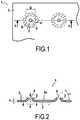
- the prosthetic plate 1intended for the repair of walls, in particular in the hernia area, comprises a textile support 2 of which at least one of the faces 2a is surmounted by anti-migratory protuberances 3 formed at from the fibers or filaments making up the textile support itself.
- the textile support 2is, in the first example which will be described, a nonwoven, formed by the entanglement of fibers or thermoplastic filaments which are joined to each other by bonding, more precisely by spot thermobonding, obtained by passing a layer of fibers or filaments between two engraved heating cylinders. It is in particular a nonwoven fabric of 45 to 100 g / m 2 , made from polypropylene filaments. In this example the binding has a density of 36 points / cm 2 , each point being of the order of 0.1 mm 2 .
- each protrusion 3has the shape of a truncated cone, the small open base of the truncated cone corresponding to a perforation 4, that is to say a through hole, formed in the textile support 2.
- the angle ⁇ of inclination of the truncated cone, with respect to the general plane of the textile support 2is of the order of 45 ° in the example illustrated in FIG. figure 2 . This value is not limiting. In the case where this angle ⁇ is 90 °, the protuberance then has a configuration which is not frustoconical but cylindrical.
- the protuberances 3could possibly be formed during the manufacture of the textile support 2. However for simplification they are formed on the textile support already made by pushing outwards along the arrow F of the figure 2 the constituent fibers or filaments of said support 2 in a localized zone 5.
- this localized zone 5has been circumscribed by a peripheral portion, in particular an annular portion 6 in which the constituent fibers or filaments of the textile support 2 have been heat-welded, in particular by ultrasound.
- the fibers or filaments which are heat-welded in said portion 6do not tend to move when pushing along the arrow F fibers or non-heat-sealed filaments which are inside this peripheral portion 6
- the thermo-weldingprovides a certain consolidation of the textile support around each protrusion 3. This consolidation effect, allowing only the fibers or filaments of the localized zone 5 to move to form the protuberance 3, is obtained whatever the shape. of the peripheral zone, that this one has the form of a ring as in the illustrated example or any other form.
- the configuration of the protuberance 3is, in this case, a function of the tool used to push or stamp the textile support 2 in the localized zone 5.
- this configurationmay be frustoconical as in the illustrated example, cylindrical even conical if there is no perforation 4 or wave, forming a wave effect having not an axis of symmetry as for frustoconical, conical or cylindrical configurations but a plane of symmetry.
- the perforations 4, made in the textile support 2have the primary function of facilitating on the one hand the drainage of body fluids coming into contact with the plate and on the other hand the tissue colonization of the plate, in particular when the latter has a microporous structure, as is the case of a thermo-bonded nonwoven. It is this colonization which makes it possible to obtain a definitive fixation of the plate 1 within a period which is generally fifteen days after implantation.
- the second function of these perforationsis to increase, by the edges that they form when they are arranged at the level of the protuberances 3, as many complementary points of friction, contributing to the anti-migratory effect of the protuberances themselves.
- the prosthetic plate 1 of the figure 1is for example obtained in two successive steps.
- the first stepconsists, starting from a large textile support, in two simultaneous operations of cutting and punching by stamping.
- the cutting operationmakes it possible to give the plate 1 its external dimensions, for example a rectangle of 17 cm ⁇ 15 cm.
- the perforation operationmakes it possible to make as many through-holes as there are perforations 4 desired in number and size, for example circular perforations of the order of 1 to 2 mm in diameter, with 0.5 to 2 perforations. / cm 2 .
- the second stepconsists of two simultaneous ultrasonic thermo-welding operations according to the annular portion 6 and embossing of the textile support inside this annular portion 6.
- an ultrasonic toolcomprising a male part and a female part.
- the prosthetic plateis placed on the female part.
- the male partcomprises as many unit sonotrodes as perforations, each unit sonotrode bearing on the prosthetic plate in the annular portion and having a central extension forming embossing tip.
- the placement of the prosthetic plate 2 on the female partis such that each perforation 4 is centered relative to to a ring annular sonotrode and its embossing tip.
- the unit sonotrodescarry out the localized fusion of the fibers or filaments of the prosthetic prosthesis in the annular portion 6 and the embossing tip deforms the structure of the textile support at interior of this annular portion 6, displacing the non-heat-sealed fibers or filaments to form the protuberances 3.
- each protuberanceis, in the example illustrated in FIG. figure 2 substantially in the order of the thickness e of the prosthetic plate 2.
- this height his preferably of the order of twice this thickness e, not being normally greater than three times this thickness e to avoid the risks of aggressiveness with regard to the organic tissues.
- the plate 1is provided with anti-migratory protrusions on both sides.
- the same toolcan be used to form the annular zones and the protuberances on both sides in two successive steps, the first to form the protuberances and the annular zones. corresponding to said protuberances on one side and the second to form the protuberances and corresponding annular areas on the other side, after reversal of the textile support.
- the textile support 12is provided on its upper face 12a protuberances 13.
- Each protrusion 13is delimited by a peripheral portion 16 and has a central perforation 14.
- This same prosthetic plate 11comprises, on its other internal face 12b, protuberances 23 delimited by a peripheral portion 26, in dotted lines on the figure 3 and also having a central perforation 24. All these protuberances 13 and 23 are regularly distributed in staggered rows and alternately on one side 12a to the other 12b.
- the protuberances 13, 23form parallel alignments both longitudinal and transverse, these alignments being offset from one face to the other by a distance which is equal to half of the spacing between two adjacent protuberances.
- the protuberances 13, 23have substantially the same height h.
- the annular peripheral portion 6, 16, 26preferably has an inner diameter D which is of the order of 2 to 5 mm and a width 1 which is of the order of 0.5 mm.
- a plate 31which has on its two faces protuberances 13, 23 identical to those of the example of FIG. figure 3 .
- This prosthetic plate 31further comprises a radiopaque marking 36 which is intended to allow radiological monitoring of the prosthetic plate 31 after implantation. This follow-up must make it possible to check the correct positioning of the plate during the period preceding the fixation by tissue colonization.
- plaque control over timeis made possible by performing comparative radiographs and measuring the intervals of the radiopaque frame, allowing in particular to evaluate a possible movement of the plate during its aging.
- the radiological follow-upmust also make it possible to locate the location of the plate for a new intervention on another pathology requiring the surgical passage by the area where said plate is located. Finally, it must allow the study, by a simple and inexpensive examination, of the evolution over time of the textile support in terms of shrinkage and aging, in particular the comparative study of the radio-opaque frame allows, in case of recidivism, to better understand the cause.
- the radiopaque markingis in the form of lines 33, 34 to form a regular grid.
- the pitch P of the gridis between 2 and 45 mm, preferably of the order of 15 mm for a rectangular plate 17 cm x 15 cm.
- the lines 33,34pass between the protuberances 13, 23; this is not, however, limiting.
- the radiopaque marking itselfcan in particular be obtained by localized impregnation, according to the grid lines or according to any other pattern of the textile support (32), with a silicone composition comprising a radiopaque filler, which load may in particular be barium sulphate or tantalum.
- the grid 32is formed of longitudinal lines 33 and transverse lines 34 delimiting squares 35, each square containing one or two protuberances 13, 23. Moreover, the grid 32 occupies the entire surface of the plate 31. These particular provisions are not not exclusive, including the grid that can occupy only part of the plate 31.
- the textile support 41 of the plate 40is a fabric of the 3D or three-dimensional type, consisting of two layers connected by connecting threads 42 obtained by knitting on a loom double chain needle.
- itwas made from polyester multi-filaments for the two layers 43 and polyester monofilaments with respect to the connecting threads 42. It has a macroporous structure honeycomb with hexagonal mesh forming regular days or pores 44.
- the technique of formation of the protuberancesis the same as that described above, except that there are no perforations formed in the textile support 41 prior to the formation of the protuberances and that heat-sealing occurs on all the fibers or filaments in the determined area where the protuberance will be formed.
- Thisis obtained by stamping and heat sealing using two complementary tools, male and female, having the desired configuration for the protrusion, with or without peripheral portion.
- the heat-sealingis performed by applying an ultrasonic treatment, using these two tools, which are in this case sonotrodes, on the fibers or filaments which are deformed and compressed between the two male and female tools.
- the protuberance 45comprises, on its substantially frustoconical wall, days 46 which result at least in part from the deformation, in particular the elongation, of the days 44 existing in the structure of the 3D knit 41, deformation which occurs during the stamping said knit 41 by the male embossing tool.
- days 46allow the tissue colonization of the plate 41 at the level of the protuberances 45 themselves, which are most immediately in contact with the organic tissues.
- the anchoring of the plate 40 due to tissue colonizationis faster than if this colonization did not occur at the level of the protuberances 45 but only at the other days 44 of the three-dimensional knit 41.
- All the protuberancesdo not comprise not necessarily days and days present in the protuberances do not all have the same size and the same configuration since it depends on the structure of the textile support in the determined area in which intervenes in a random manner the action of the pushing tools for form the protuberance.
- the largest dimension of the days in each protrusioncan be of the order of 1 to 1.5 mm.
- the textile support 2has been referred to as the element forming the prosthetic plate. This is not exclusive.
- the textile supportmay include an impregnation the purpose of which is to give the plate a certain shape memory, allowing it to be wound on itself for its introduction into a trocar and to be deployed spontaneously when released from the trocar. . It may be an impregnation of collagen, which has the advantage of accelerating tissue colonization. It can also be a polyurethane impregnation.
- the textile supportmay also comprise on one of its faces an anti-adherent coating, in particular on the face that does not include antimigratory protuberances.
- anti-adherent coatingis meant a coating which is able to avoid or at least to strongly limit the adhesions between the plate and the parts of the body against which it comes into contact, once implanted, especially the viscera. It may be a coating of collagen, polysaccharide or other resorbable biopolymer or not.
- the formation of the protuberances as described abovecan be carried out either on the textile support alone before impregnation or before coating or respectively on the already impregnated textile support or on the textile support already coated with its coating.
Landscapes
- Health & Medical Sciences (AREA)
- Engineering & Computer Science (AREA)
- Life Sciences & Earth Sciences (AREA)
- Animal Behavior & Ethology (AREA)
- Oral & Maxillofacial Surgery (AREA)
- Biomedical Technology (AREA)
- Heart & Thoracic Surgery (AREA)
- Vascular Medicine (AREA)
- Cardiology (AREA)
- Transplantation (AREA)
- General Health & Medical Sciences (AREA)
- Public Health (AREA)
- Veterinary Medicine (AREA)
- Textile Engineering (AREA)
- Prostheses (AREA)
- Finishing Walls (AREA)
Description
Translated fromFrenchLa présente invention concerne une plaque prothétique c'est-à-dire une plaque qui est implantable pour la réfection de parois, notamment dans le traitement des hernies.The present invention relates to a prosthetic plate that is to say a plate that is implantable for the repair of walls, particularly in the treatment of hernias.
Dans le domaine chirurgical, on utilise le terme plaque pour désigner de manière générale une pièce souple, dans un matériau biocompatible et généralement poreux, pièce qui est mise en oeuvre pour la confection d'une prothèse, notamment destinée à renforcer une paroi défectueuse. La prothèse en elle-même peut être réalisée à partir d'une seule plaque comme dans le document
Pour une parfaite efficacité de la prothèse, il importe que celle-ci reste bien en place dans la position qui lui a été donnée lors de son implantation. Pour ce faire, le praticien réalise la fixation de la prothèse aux structures environnantes à l'aide d'agrafes ou de fils de suture, comme dans le document
On connaît par le document
Cependant le demandeur est d'avis que la simple structure de la couche externe, à savoir une structure fibrillaire non-tissée, n'est pas de nature à éviter le déplacement de la plaque dans la période qui suit l'implantation et qui précède la colonisation tissulaire.However, the plaintiff is of the opinion that the simple structure of the outer layer, namely a non-woven fibrillar structure, is not likely to prevent displacement of the plate in the period following implantation and which precedes the tissue colonization.
C'est l'objet de la présente invention que de proposer une plaque implantable pour la réfection de parois qui pallie les inconvénients des plaques précitées d'une part en ce qu'elle ne nécessite pas une fixation par agrafage ou suturage et d'autre part qui assure de manière fiable le maintien en place de la prothèse dans la période qui suit l'implantation de ladite prothèse par le chirurgien.It is the object of the present invention to provide an implantable plate for the repair of walls which overcomes the disadvantages of the aforementioned plates on the one hand in that it does not require fixing by stapling or suturing and other which reliably ensures the retention of the prosthesis in the period following the implantation of said prosthesis by the surgeon.
Le document
De manière connue, la plaque implantable de la présente invention comporte un support textile et présente des protubérances. Elle se caractérise en ce que les protubérances sont formées dans le support textile lui-même, sur au moins l'une de ses faces. Ainsi, selon la disposition particulière de la présente invention, lorsque la plaque est implantée, la face du support textile qui comporte les protubérances vient en contact avec les tissus organiques et les protubérances qui sont constituées par les fibres ou filaments du support textile forment autant de zones de friction entre la plaque et lesdits tissus, créant des forces de frottement empêchant le déplacement de ladite plaque par rapport auxdits tissus.In known manner, the implantable plate of the present invention comprises a textile support and has protuberances. It is characterized in that the protuberances are formed in the textile support itself, on at least one of its faces. Thus, according to the particular arrangement of the present invention, when the plate is implanted, the face of the textile support which comprises the protuberances comes into contact with the organic tissues and the protuberances which are constituted by the fibers or filaments of the textile support form as many areas of friction between the plate and said tissues, creating frictional forces preventing movement of said plate relative to said tissue.
Dans un mode préféré de réalisation, les protubérances ont une configuration conique, une telle configuration facilitant la pénétration des protubérances dans les tissus organiques. Cette configuration n'est cependant pas exclusive, les protubérances pouvant avoir notamment une forme ondulatoire ou cylindrique.In a preferred embodiment, the protuberances have a conical configuration, such a configuration facilitating the penetration of the protuberances in the organic tissues. This configuration is however not exclusive, the protuberances may have in particular an undulating or cylindrical shape.
Selon une variante de réalisation, le support textile comporte des perforations, lesquelles sont principalement destinées à favoriser le drainage des fluides corporels et éventuellement à favoriser la colonisation tissulaire dans le cas où la structure elle-même du support textile n'est pas suffisamment ouverte. De préférence ces perforations sont disposées au niveau des protubérances en sorte que les contours de la perforation forment des arêtes qui augmentent l'effet de friction de la protubérance proprement dite.According to an alternative embodiment, the textile support comprises perforations, which are mainly intended to promote the drainage of body fluids and possibly to promote tissue colonization in the case where the structure itself of the textile support is not sufficiently open. Preferably these perforations are arranged at the level of the protuberances so that the contours of the perforation form ridges which increase the friction effect of the protuberance itself.
De préférence lorsque la protubérance possède un axe de symétrie, la perforation est un orifice centré sur cet axe. Ainsi, dans le cas où la protubérance a une configuration conique, la présence de la perforation fait qu'en réalité la protubérance a une forme de tronc de cône. Le support textile est constitué au moins en partie de fibres ou filaments thermoplastiques et chaque protubérance est formée dans une zone déterminée du support textile par déformation de la structure du support et par thermosoudage d'au moins certaines desdites fibres ou filaments de ladite zone. Par exemple la protubérance peut être formée à l'intérieur d'une portion périphérique, notamment annulaire, de ladite zone dans laquelle lesdites fibres ou filaments sont thermo-soudés. Le thermo-soudage des fibres ou filaments constitutifs de la portion périphérique assure à ladite portion une certaine rigidité, ce qui permet de former la protubérance en repoussant vers l'extérieur du plan du support textile et donc en déformant la structure du support textile, formé de fibres ou filaments non thermo-soudés, qui se trouve à l'intérieur de ladite portion périphérique.Preferably when the protuberance has an axis of symmetry, the perforation is an orifice centered on this axis. Thus, in the case where the protuberance has a conical configuration, the presence of the perforation in fact makes the protuberance has the shape of a truncated cone. The textile support consists at least in part of thermoplastic fibers or filaments and each protuberance is formed in a given zone of the textile support by deformation of the support structure and heat sealing of at least some of said fibers or filaments of said zone. For example, the protuberance may be formed inside a peripheral portion, in particular an annular portion, of said zone in which said fibers or filaments are heat-welded. The thermo-welding of the fibers or filaments constituting the peripheral portion provides said portion with a certain rigidity, which makes it possible to form the protuberance by pushing outwardly of the plane of the textile support and thus by deforming the structure of the textile support formed fibers or filaments not heat-welded, which is inside said peripheral portion.
De préférence, lorsque le support textile comporte des perforations, celles-ci sont centrées par rapport à la portion périphérique de la zone déterminée.Preferably, when the textile support comprises perforations, these are centered with respect to the peripheral portion of the determined zone.
Cependant, de préférence, la protubérance est formée par déformation et par thermosoudage de toutes les fibres ou filaments de la zone déterminée du support textile. Par exemple la déformation intervient par emboutissage entre deux outils complémentaires, mâle et femelle, ayant la configuration souhaitée pour la protubérance et le thermosoudage intervient par application, à l'aide des mêmes outils, d'un traitement apte à réaliser le thermosoudage des fibres ou filaments déformés lors de l'emboutissage. Dans ce cas il y a, dans un premier temps, déformation de la structure initiale du support textile, notamment le déplacement des fibres ou filaments les uns par rapport aux autres jusqu'à obtenir la configuration souhaitée pour la protubérance, et il y a, dans un second temps, thermosoudage des fibres ou filaments dans leur nouvelle disposition. La fusion au moins superficielle des fibres ou filaments qui est développée lors de l'opération de thermosoudage apporte une certaine rigidité à l'ensemble des fibres ou filaments de la protubérance, ce qui augmente ses propriétés frictionnelles et donc le caractère antimigratoire de la plaque.However, preferably, the protrusion is formed by deformation and heat sealing of all the fibers or filaments of the determined area of the textile support. For example, the deformation is effected by stamping between two complementary tools, male and female, having the desired configuration for the protuberance and the heat-sealing is performed by applying, using the same tools, a treatment suitable for heat-sealing the fibers or deformed filaments during stamping. In this case there is, initially, deformation of the initial structure of the textile support, in particular the displacement of the fibers or filaments with respect to each other until the desired configuration for the protuberance is obtained, and there is, in a second time, heat-sealing fibers or filaments in their new arrangement. The at least superficial melting of the fibers or filaments which is developed during the heat-sealing operation brings a certain rigidity to all the fibers or filaments of the protuberance, which increases its frictional properties and therefore the antimigratory character of the plate.
Le thermo-soudage des fibres ou filaments thermoplastiques est réalisé notamment par ultrasons.Thermo-welding thermoplastic fibers or filaments is carried out in particular by ultrasound.
Selon une variante de réalisation, le support textile est un non-tissé qui est thermo-lié par points.According to an alternative embodiment, the textile support is a nonwoven which is thermo-bonded by points.
Selon une autre variante de réalisation, le support textile est un tissu du type 3D ou tridimensionnel, constitué de deux couches reliées par des fils de liaison. Cela permet de faire varier plus largement les caractéristiques du support textile, notamment son épaisseur, le choix des composants qui le constituent ainsi que sa porosité. Il peut être obtenu soit par tissage soit par tricotage.According to another variant embodiment, the textile support is a fabric of the 3D or three-dimensional type, consisting of two layers connected by connecting threads. This makes it possible to vary more widely the characteristics of the textile support, in particular its thickness, the choice of components that constitute it as well as its porosity. It can be obtained either by weaving or by knitting.
Par tissage, il est obtenu par superposition d'une nappe de fils de chaîne et de plusieurs nappes de fils de trame ou par superposition de plusieurs nappes de fils de chaîne et de fils de trame. La liaison de ces différentes nappes est assurée soit par certains des fils de chaîne d'au moins l'une des nappes de fils de chaîne de la superposition soit par une nappe supplémentaire de fils de chaîne, dite chaîne de liage.By weaving, it is obtained by superposition of a sheet of warp threads and several plies of weft threads or by superposition of several plies of warp threads and weft threads. The connection of these different plies is ensured either by some of the warp son of at least one of the warp son plies of the superposition or by an additional sheet of warp son, said binding chain.
Par tricotage, il est obtenu sur un métier chaîne double fonture, dans lequel la liaison des deux couches respectivement tricotées sur chaque fonture est assurée par une nappe de chaîne supplémentaire qui travaille alternativement sur l'une et l'autre fontures.By knitting, it is obtained on a loom double chain needle, in which the connection of the two respectively knitted layers on each needle bed is provided by an additional chain ply which works alternately on one and the other bedbugs.
Selon une variante de réalisation, au moins certaines protubérances comportent des jours aptes à permettre la colonisation cellulaire de l'implant au niveau desdites protubérances et également un certain drainage des fluides corporels. Cela permet d'éviter de former des perforations dans le support textile.According to an alternative embodiment, at least some protuberances comprise days capable of allowing the cellular colonization of the implant at the level of said protuberances and also a certain drainage of the body fluids. This makes it possible to avoid forming perforations in the textile support.
Lorsque les protubérances sont formées en repoussant les fibres ou filaments constitutifs du support textile, on obtient, lors de cette opération, un déplacement relatif de certaines des fibres ou de certains des filaments susceptible de créer des jours dans au moins certaines protubérances. La présence ou non d'un ou plusieurs jours dans une protubérance, la taille et la configuration de chaque jour sont des paramètres assez aléatoires puisqu'ils dépendent non seulement de la structure, plus ou moins ouverte, du support textile mais aussi de l'emplacement, sur le support textile, de la zone où agissent localement les outils créant la protubérance. Si la structure du support textile est relativement fermée et que les outils agissent dans une zone où il y a une forte densité de fibres ou filaments, la protubérance pourra ne pas contenir de jour. Au contraire, la protubérance sera ajourée si la structure du support textile est elle-même ajourée et que les outils agissent dans une zone comportant déjà au moins une partie de jour.When the protuberances are formed by pushing back the fibers or filaments constituting the textile support, during this operation, a relative displacement of some of the fibers or of some of the filaments that can create days in at least some protuberances is obtained. The presence or not of one or more days in a protuberance, the size and the configuration of each day are rather random parameters since they depend not only on the structure, more or less open, of the textile support but also of the location, on the textile support, of the area where the tools creating the protuberance act locally. If the structure of the textile support is relatively closed and the tools operate in an area where there is a high density of fibers or filaments, the protuberance may not contain a day. On the contrary, the protuberance will be perforated if the structure of the textile support is itself perforated and the tools act in an area already having at least a portion of day.
De préférence, pour augmenter la probabilité d'avoir des protubérances ajourées, on choisit comme support textile un tissu tridimensionnel obtenu par tricotage, comme mentionné ci-dessus, qui permet d'avoir un caractère ajouré plus prononcé et de maîtriser ce caractère ajouré plus facilement que celui obtenu par tissage.Preferably, in order to increase the probability of having perforated protuberances, a three-dimensional fabric obtained by knitting, as mentioned above, which has a perforated character, is chosen as textile support. more pronounced and master this openwork character more easily than that obtained by weaving.
Selon l'application visée, la plaque de la présente invention peut présenter des protubérances sur une seule face ou sur ses deux faces.Depending on the intended application, the plate of the present invention may have protrusions on one side or on both sides.
Dans un mode de réalisation particulier, la plaque comporte, sur les deux faces du support textile, des protubérances dont la hauteur est sensiblement égale ou supérieure à l'épaisseur (e) dudit support, de préférence inférieure à trois fois ladite épaisseur, notamment de l'ordre de deux fois ladite épaisseur. Si l'épaisseur dépasse trois fois l'épaisseur du support textile, il y a un risque d'agressivité des fibres ou filaments qui constituent lesdites protubérances.In a particular embodiment, the plate comprises, on both sides of the textile support, protuberances whose height is substantially equal to or greater than the thickness (e) of said support, preferably less than three times said thickness, in particular of the order of twice said thickness. If the thickness exceeds three times the thickness of the textile support, there is a risk of aggressiveness of the fibers or filaments which constitute said protuberances.
De préférence ces protubérances sont régulièrement réparties, en quinconce et en alternance d'une face à l'autre, à raison de 0,5 à 2 protubérances/cm2. Dans un exemple précis de réalisation de protubérances formées par emboutissage à l'intérieur d'une zone annulaire dans laquelle les fibres ou filaments thermoplastiques du support textile étaient thermo-soudées par ultrasons, la zone annulaire avait un diamètre intérieur de l'ordre de 2 à 5 mm et une largeur de l'ordre de 0,5 mm.Preferably these protuberances are regularly distributed, staggered and alternating from one face to the other, at the rate of 0.5 to 2 protuberances / cm2 . In a specific embodiment of protuberances formed by stamping inside an annular zone in which the thermoplastic fibers or filaments of the textile support were thermo-welded by ultrasound, the annular zone had an internal diameter of the order of 2 at 5 mm and a width of the order of 0.5 mm.
Selon une variante de réalisation, le support textile est imprégné, par exemple de collagène qui favorise la colonisation cellulaire ou encore de polyuréthanne, ladite imprégnation étant apte à conférer à la plaque une certaine mémoire de forme. Le but est de permettre que la plaque puisse être enroulée sur elle-même pour son introduction dans un trocart et se déployer spontanément lors de sa libération du trocart.According to an alternative embodiment, the textile support is impregnated, for example collagen which promotes cell colonization or polyurethane, said impregnation being able to confer on the plate a certain shape memory. The purpose is to allow the plate to be wound on itself for its introduction into a trocar and to deploy spontaneously when released from the trocar.
Selon une variante de réalisation, le support textile comporte sur l'une de ses faces une enduction anti-adhérente, en particulier sur la face ne comportant pas de protubérances antimigratoires. On entend par enduction anti-adhérente une enduction qui est apte à éviter ou tout au moins à limiter fortement les adhérences entre la plaque et les parties du corps contre laquelle elle vient en contact, une fois implantée, notamment les viscères. Il peut s'agir d'une enduction de collagène, de polysaccharide ou autre biopolymère résorbable ou non.According to an alternative embodiment, the textile support comprises on one of its faces an anti-adherent coating, in particular on the face having no antimigratory protuberances. By non-stick coating is meant a coating which is able to avoid or at least to strongly limit the adhesions between the plate and the parts of the body against which it comes into contact, once implanted, especially the viscera. It may be a coating of collagen, polysaccharide or other resorbable biopolymer or not.
L'implantation d'une prothèse quelle qu'elle soit doit pouvoir faire l'objet d'un suivi par le chirurgien, de manière à vérifier le comportement de la prothèse dans le temps. Dans le document
Toutefois la présence de fils métalliques dans la plaque prothétique peut être un inconvénient, notamment du fait qu'elle augmente la rigidité de celle-ci et qu'elle augmente son coût de fabrication. De plus il n'est guère envisageable d'introduire des fils métalliques dans une structure autre que tissée ou tricotée. Pour pallier ces inconvénients, la plaque prothétique de la présente invention comporte un marquage radio-opaque sur toute ou partie de la surface du support textile.However, the presence of metal son in the prosthetic plate can be a disadvantage, especially because it increases the rigidity thereof and increases its manufacturing cost. In addition it is hardly possible to introduce metal son in a structure other than woven or knitted. To overcome these disadvantages, the prosthetic plate of the present invention comprises a radiopaque marking on all or part of the surface of the textile support.
Dans une variante de réalisation, ce marquage radio-opaque résulte de l'imprégnation localisée du support textile par une composition siliconée comportant une charge radio-opaque, notamment une charge de sulfate de baryum ou de tantale.In an alternative embodiment, this radiopaque marking results from the localized impregnation of the textile support with a silicone composition comprising a radiopaque filler, in particular a filler of barium sulfate or tantalum.
Selon un mode de réalisation, le marquage se présente sous la forme de lignes pour constituer un quadrillage régulier.According to one embodiment, the marking is in the form of lines to form a regular grid.
Dans un exemple précis et préféré, le pas du quadrillage est compris entre 2 et 45 mm, de préférence de l'ordre de 15 mm.In a specific and preferred example, the pitch of the grid is between 2 and 45 mm, preferably of the order of 15 mm.
La présente invention sera mieux comprise à la lecture de la description d'exemples de réalisation d'une plaque prothétique comportant des protubérances anti-migratoires, illustrés par le dessin annexé dans lequel :
- La
figure 1 est une représentation schématique en vue de dessus d'une portion de plaque prothétique comportant deux protubérances tronconiques, - La
figure 2 est une représentation schématique en coupe de la plaque prothétique de lafigure 1 selon le plan II-II, - La
figure 3 est une représentation schématique en vue de dessus d'une plaque prothétique présentant des protubérances en relief sur ses deux faces, - La
figure 4 est une représentation schématique en vue de dessus de la plaque de lafigure 3 comportant un marquage radio-opaque sous forme d'un quadrillage passant entre les protubérances, et - La
figure 5 est une photographie prise au microscope illustrant une protubérance formée dans un tricot tridimensionnel.
- The
figure 1 is a diagrammatic representation in plan view of a prosthetic plate portion comprising two frustoconical protuberances, - The
figure 2 is a schematic representation in section of the prosthetic plate of thefigure 1 according to plan II-II, - The
figure 3 is a schematic representation in plan view of a prosthetic plate having raised protuberances on both sides, - The
figure 4 is a schematic representation in top view of the plate of thefigure 3 having a radiopaque marking in the form of a grid passing between the protuberances, and - The
figure 5 is a photograph taken under a microscope illustrating a protuberance formed in a three-dimensional knit.
De manière générale selon l'invention, la plaque prothétique 1, destinée à la réfection de parois notamment dans le domaine des hernies, comporte un support textile 2 dont au moins l'une des faces 2a est surmontée de protubérances anti-migratoires 3 formées à partir des fibres ou filaments composant le support textile lui-même.In general, according to the invention, the
Ce sont les fibres ou filaments qui, venant en contact direct avec les tissus organiques, confèrent auxdites protubérances un effet anti-migratoire, empêchant la migration de la plaque 1 une fois que celle-ci a été implantée par le chirurgien sans être fixée d'une quelconque manière, que ce soit par des moyens mécaniques tels que des agrafes ou des fils de suture ou par tout autre moyen.It is the fibers or filaments which, coming into direct contact with the organic tissues, confer on said protuberances an anti-migratory effect, preventing the migration of the
Le support textile 2 est, dans le premier exemple qui va être décrit, un non-tissé, formé par l'enchevêtrement de fibres ou de filaments thermoplastiques qui sont solidarisés les uns aux autres par liage, plus précisément par thermoliage par points, obtenu par passage d'une nappe de fibres ou de filaments entre deux cylindres chauffants gravés. Il s'agit en particulier d'un non-tissé faisant de 45 à 100g/m2, fait à partir de filaments de polypropylène. Dans cet exemple le liage a une densité de 36 points/cm2, chaque point faisant de l'ordre de 0,1 mm2.The
Dans le mode de réalisation illustré aux
Les protubérances 3 pourraient éventuellement être formées lors de la fabrication du support textile 2. Cependant par simplification elles sont formées sur le support textile déjà réalisé en repoussant vers l'extérieur selon la flèche F de la
Dans un mode précis de réalisation, cette zone localisée 5 a été circonscrite par une portion périphérique, notamment annulaire 6 dans laquelle les fibres ou filaments constitutifs du support textile 2 ont été thermo-soudées notamment par ultrasons. Ainsi les fibres ou filaments qui sont thermo-soudées dans ladite portion 6 n'ont pas tendance à se déplacer lorsqu'on repousse selon la flèche F les fibres ou filaments non thermo-soudées qui se trouvent à l'intérieur de cette portion périphérique 6. Le thermo-soudage apporte une certaine consolidation du support textile autour de chaque protubérance 3. Cet effet de consolidation, permettant que seules les fibres ou filaments de la zone localisée 5 puissent se déplacer pour former la protubérance 3 est obtenu quelle que soit la forme de la zone périphérique, que celle-ci ait la forme d'un anneau comme dans l'exemple illustré ou toute autre forme.In one particular embodiment, this localized zone 5 has been circumscribed by a peripheral portion, in particular an
La configuration de la protubérance 3 est, dans ce cas, fonction de l'outil servant au repoussage ou emboutissage du support textile 2 dans la zone localisée 5. Comme indiqué ci-dessus cette configuration peut être tronconique comme dans l'exemple illustré, cylindrique, voire conique s'il n'y a pas de perforation 4 ou encore ondulatoire, formant un effet de vague ayant non pas un axe de symétrie comme pour les configurations tronconique, conique ou cylindrique mais un plan de symétrie.The configuration of the
Les perforations 4, pratiquées dans le support textile 2, ont pour fonction première de faciliter d'une part le drainage des fluides corporels venant au contact de la plaque et d'autre part la colonisation tissulaire de la plaque, en particulier lorsque celle-ci a une structure microporeuse, comme c'est le cas d'un non-tissé thermo-lié. C'est cette colonisation qui permet d'obtenir une fixation définitive de la plaque 1 dans un délai qui est généralement de quinze jours après l'implantation. La fonction seconde de ces perforations est d'augmenter, par les arêtes qu'elles forment lorsqu'elles sont disposées au niveau des protubérances 3, autant de points complémentaires de friction, contribuant à l'effet anti-migratoire des protubérances elles-mêmes.The perforations 4, made in the
La plaque prothétique 1 de la
La hauteur h de chaque protubérance est, dans l'exemple illustré à la
Dans le mode de réalisation illustré aux
Cependant il peut être souhaité, notamment lorsqu'il s'agit de la réfection des hernies par voie chirurgicale, que la plaque 1 soit pourvue de protubérances anti-migratoires sur ses deux faces.However it may be desired, especially when it comes to the repair of hernias by surgery, that the
Si l'on veut mettre en oeuvre la même technique ultrasonique que ci-dessus, le même outil peut être utilisé pour former les zones annulaires et les protubérances sur les deux faces en deux étapes successives, la première pour former les protubérances et les zones annulaires correspondant auxdites protubérances sur une face et la seconde pour former les protubérances et les zones annulaires correspondantes sur l'autre face, après retournement du support textile.If one wants to implement the same ultrasonic technique as above, the same tool can be used to form the annular zones and the protuberances on both sides in two successive steps, the first to form the protuberances and the annular zones. corresponding to said protuberances on one side and the second to form the protuberances and corresponding annular areas on the other side, after reversal of the textile support.
Sur la
Sur les deux faces 12a et 12b, les protubérances 13, 23 ont sensiblement la même hauteur h.On both
La portion périphérique annulaire 6, 16, 26 a de préférence un diamètre intérieur D qui est de l'ordre de 2 à 5 mm et une largeur l qui est de l'ordre de 0,5 mm.The annular
Sur la
Le marquage radio-opaque se présente sous la forme de lignes 33, 34 pour constituer un quadrillage régulier. Le pas P du quadrillage est compris entre 2 et 45 mm, de préférence de l'ordre de 15 mm pour une plaque rectangulaire faisant 17 cm x 15 cm. Dans l'exemple illustré à la
Grâce à la disposition en quadrillage régulier de ce marquage, il est possible, lors de l'examen radioscopique, de vérifier s'il y a ou non une évolution dans les distances séparant les lignes adjacentes du quadrillage et par conséquent de constater une éventuelle rétraction du support textile dans lequel est formée la plaque.Thanks to the regular grid layout of this marking, it is possible, during the radioscopic examination, to check whether or not there is an evolution in the distances separating the adjacent lines of the grid and consequently to note a possible retraction. of the textile support in which the plate is formed.
Le marquage radio-opaque proprement dit peut en particulier être obtenu par imprégnation localisée, selon les lignes du quadrillage ou selon tout autre motif du support textile (32), par une composition siliconée comportant une charge radio-opaque, charge qui peut notamment être du sulfate de baryum ou du tantale.The radiopaque marking itself can in particular be obtained by localized impregnation, according to the grid lines or according to any other pattern of the textile support (32), with a silicone composition comprising a radiopaque filler, which load may in particular be barium sulphate or tantalum.
Sur la
Dans un second exemple de réalisation, qui va être décrit en référence à la
La technique de formation des protubérances est la même que celle qui a été décrite ci-dessus, exception faite qu'il n'y a pas de perforations formées dans le support textile 41 préalablement à la formation des protubérances et que le thermosoudage intervient sur toutes les fibres ou filaments se trouvant dans la zone déterminée où va être formée la protubérance. Ceci est obtenu par emboutissage et thermosoudage à l'aide de deux outils complémentaires, mâle et femelle, ayant la configuration souhaitée pour la protubérance, avec ou sans portion périphérique. Le thermosoudage intervient par application d'un traitement ultrasonique, à l'aide de ces deux outils qui sont en l'occurrence des sonotrodes, sur les fibres ou filaments qui sont déformés et comprimés entre les deux outils mâle et femelle. Dans ce cas il y a, dans un premier temps, déformation de la structure initiale du support textile, notamment le déplacement des fibres ou filaments les uns par rapport aux autres jusqu'à obtenir la configuration souhaitée pour la protubérance, et il y a, dans un second temps, thermosoudage des fibres ou filaments dans leur nouvelle disposition. La fusion au moins superficielle des fibres ou filaments qui est développée lors de l'opération de thermosoudage apporte une rigidité certaine à l'ensemble des fibres ou filaments de la protubérance, ce qui augmente ses propriétés frictionnelles et donc le caractère antimigratoire de la plaque.The technique of formation of the protuberances is the same as that described above, except that there are no perforations formed in the
On voit clairement sur la
La dimension la plus grande des jours dans chaque protubérance peut être de l'ordre de 1 à 1,5 mm.The largest dimension of the days in each protrusion can be of the order of 1 to 1.5 mm.
Dans la description ci-dessus il n'a été question que du support textile 2, comme élément formant la plaque prothétique. Ceci n'est pas exclusif. Le support textile peut comporter une imprégnation dont le but est de conférer à la plaque une certaine mémoire de forme, permettant que celle-ci puisse être enroulée sur elle-même pour son introduction dans un trocart et se déployer spontanément lors de sa libération du trocart. Il peut s'agir d'une imprégnation de collagène, qui présente l'avantage d'accélérer la colonisation tissulaire. Il peut aussi s'agir d'une imprégnation de polyuréthanne.In the above description only the
Le support textile peut également comporter sur l'une de ses faces une enduction anti-adhérente, en particulier sur la face ne comportant pas de protubérances antimigratoires. On entend par enduction anti-adhérente une enduction qui est apte à éviter ou tout au moins à limiter fortement les adhérences entre la plaque et les parties du corps contre laquelle elle vient en contact, une fois implantée, notamment les viscères. Il peut s'agir d'une enduction de collagène, de polysaccharide ou autre biopolymère résorbable ou non.The textile support may also comprise on one of its faces an anti-adherent coating, in particular on the face that does not include antimigratory protuberances. By non-stick coating is meant a coating which is able to avoid or at least to strongly limit the adhesions between the plate and the parts of the body against which it comes into contact, once implanted, especially the viscera. It may be a coating of collagen, polysaccharide or other resorbable biopolymer or not.
Dans le cas où le support textile est imprégné ou comporte une enduction anti-adhérente, la formation des protubérances telle que décrite ci-dessus peut intervenir soit sur le support textile seul avant imprégnation ou avant enduction soit respectivement sur le support textile déjà imprégné ou sur le support textile déjà revêtu de son enduction.In the case where the textile support is impregnated or comprises a non-stick coating, the formation of the protuberances as described above can be carried out either on the textile support alone before impregnation or before coating or respectively on the already impregnated textile support or on the textile support already coated with its coating.
Claims (13)
- An implantable plate (1) for reconstruction of walls, comprising a textile support (2,41) and having protuberances, said protuberances having a conical or cylindrical configuration,characterised in that the protuberances (3) are formed in at least one of the faces (2a) of said textile support (2), the fibres or filaments which constitute said protuberances lending them an anti-migratory effect,in that the textile support is constituted at least in part by thermoplastic fibres or filaments and each protuberance (3,45) is formed in a determined zone (5) of the textile support (2,41) by deformation of the structure of the support (2,41) and by thermowelding of at least some of said fibres or filaments of said zone, andin that said textile support is a non-woven material which is thermo-bonded at points or, a tissue of three-dimensional type, constituted of two layers (43) joined by connecting threads (42), especially made by weaving or by knitting.
- The plate according to claim 1,characterised in that the textile support (2) comprises perforations (4), especially arranged at the level of the protuberances (3).
- The plate according to claim 1 or 2,characterised in that each protuberance (3, 45) is formed by swaging inside said determined zone (5) in which all or part of said fibres or filaments are thermowelded, especially by ultrasound.
- The plate according to claims 2 and 3,characterised in that the perforation (4) is centred relative to a peripheral portion (6) of the determined zone (5), in which portion the fibres or filaments are thermowelded.
- The plate according to claim 4,characterised in that the peripheral portion (6) is an annular portion having an inner diameter of the order of 2 to 5 mm and, preferably, a width (I) of the order of 0.5 mm
- The plate (11) according to anyone of the claims 1 to 5,characterised in that it comprises, on the two faces (12a, 12b) of the textile support (12), protuberances (13) whereof the height (h) is substantially equal to or greater than the thickness (e) of said support, preferably less than three times said thickness, especially of the order of twice said thickness.
- The plate according to anyone of the claims 1 to 6,characterised in that it comprises protuberances (13, 23), uniformly distributed in a stagger and alternating from one face to the other, at the rate of 0.5 to 2 protuberances per cm2.
- The plate (40) according to anyone of the claims 1, 3, 5 to 7,characterised in that the textile support is an open knit obtained by knitting on a double-bed warp knitting machine.
- The plate according to anyone of the claims 1, 3 and 5,characterised in that at least some of the protuberances (45) have openings (46), capable of allowing tissular colonisation of said protuberances.
- The plate according to anyone of the claims 1 to 9,characterised in that the textile support is impregnated, especially with collagen or polyurethane.
- The plate according to anyone of the claims 1 to 10,characterised in that the textile support comprises on one of its faces an anti-adherent coating, in particular on the face not having an anti-migratory protuberance.
- The plate (31) according to anyone of the claims 1 to 11,characterised in that it comprises radio-opaque marking (35) on all or part of the surface of the textile support (32), resulting especially from localised impregnation of the textile support (32) by a silicon composition comprising a radio-opaque charge, for example a charge of barium sulphate or tantalum.
- The plate according to claim 12,characterised in that the marking is in the form of lines (33, 34) to constitute a regular grid, the pitch (P) of the grid being especially comprised between 2 and 45 mm, preferably of the order of 15 mm.
Priority Applications (1)
| Application Number | Priority Date | Filing Date | Title |
|---|---|---|---|
| PL09736440TPL2391299T3 (en) | 2009-01-30 | 2009-09-04 | Implantable plate for restoring walls |
Applications Claiming Priority (2)
| Application Number | Priority Date | Filing Date | Title |
|---|---|---|---|
| FR0950600AFR2941616B1 (en) | 2009-01-30 | 2009-01-30 | IMPLANTABLE PLATE FOR THE REFLECTION OF WALLS |
| PCT/FR2009/001066WO2010086515A1 (en) | 2009-01-30 | 2009-09-04 | Implantable plate for restoring walls |
Publications (2)
| Publication Number | Publication Date |
|---|---|
| EP2391299A1 EP2391299A1 (en) | 2011-12-07 |
| EP2391299B1true EP2391299B1 (en) | 2018-01-17 |
Family
ID=40602192
Family Applications (1)
| Application Number | Title | Priority Date | Filing Date |
|---|---|---|---|
| EP09736440.0AActiveEP2391299B1 (en) | 2009-01-30 | 2009-09-04 | Implantable plate for restoring walls |
Country Status (11)
| Country | Link |
|---|---|
| US (1) | US9421078B2 (en) |
| EP (1) | EP2391299B1 (en) |
| JP (1) | JP2012516174A (en) |
| BR (1) | BRPI0924224B8 (en) |
| DK (1) | DK2391299T3 (en) |
| ES (1) | ES2665927T3 (en) |
| FR (1) | FR2941616B1 (en) |
| HU (1) | HUE036641T2 (en) |
| PL (1) | PL2391299T3 (en) |
| PT (1) | PT2391299T (en) |
| WO (1) | WO2010086515A1 (en) |
Families Citing this family (30)
| Publication number | Priority date | Publication date | Assignee | Title |
|---|---|---|---|---|
| CN103251449B (en) | 2005-10-13 | 2016-03-02 | 斯恩蒂斯有限公司 | Drug-impregnated encasement |
| US20130331928A1 (en)* | 2008-11-13 | 2013-12-12 | Chen Yang | Dialysis Graft with Thromboses Prevention Arrangement |
| FR2962646B1 (en)* | 2010-07-16 | 2012-06-22 | Sofradim Production | PROSTHETIC WITH RADIO OPAQUE ELEMENT |
| FR2972626B1 (en) | 2011-03-16 | 2014-04-11 | Sofradim Production | PROSTHETIC COMPRISING A THREE-DIMENSIONAL KNIT AND ADJUSTED |
| WO2012158590A1 (en)* | 2011-05-13 | 2012-11-22 | Atex Technologies, Inc. | Surgical mesh with dimensionally stabilized pore |
| US10188493B2 (en) | 2011-05-13 | 2019-01-29 | Atex Technologies, Inc. | Surgical mesh with dimensionally stabilized pore |
| FR2977789B1 (en) | 2011-07-13 | 2013-07-19 | Sofradim Production | PROSTHETIC FOR UMBILIC HERNIA |
| FR2977790B1 (en) | 2011-07-13 | 2013-07-19 | Sofradim Production | PROSTHETIC FOR UMBILIC HERNIA |
| US20130057655A1 (en) | 2011-09-02 | 2013-03-07 | Wen-Yueh Su | Image processing system and automatic focusing method |
| US9005308B2 (en) | 2011-10-25 | 2015-04-14 | Covidien Lp | Implantable film/mesh composite for passage of tissue therebetween |
| TWI590843B (en)* | 2011-12-28 | 2017-07-11 | 信迪思有限公司 | Films and methods of manufacture |
| FR2985170B1 (en) | 2011-12-29 | 2014-01-24 | Sofradim Production | PROSTHESIS FOR INGUINAL HERNIA |
| JP2015063763A (en)* | 2012-01-27 | 2015-04-09 | テルモ株式会社 | Three-dimensional woven fabric and manufacturing method therefor |
| DE102012005978A1 (en)* | 2012-03-23 | 2013-09-26 | Johnson & Johnson Medical Gmbh | Surgical implant |
| US10206769B2 (en) | 2012-03-30 | 2019-02-19 | Covidien Lp | Implantable devices including a film providing folding characteristics |
| FR2992662B1 (en) | 2012-06-28 | 2014-08-08 | Sofradim Production | KNIT WITH PICOTS |
| FR2992547B1 (en) | 2012-06-29 | 2015-04-24 | Sofradim Production | PROSTHETIC FOR HERNIA |
| FR2994185B1 (en) | 2012-08-02 | 2015-07-31 | Sofradim Production | PROCESS FOR THE PREPARATION OF A POROUS CHITOSAN LAYER |
| FR2995779B1 (en) | 2012-09-25 | 2015-09-25 | Sofradim Production | PROSTHETIC COMPRISING A TREILLIS AND A MEANS OF CONSOLIDATION |
| FR2995788B1 (en) | 2012-09-25 | 2014-09-26 | Sofradim Production | HEMOSTATIC PATCH AND PREPARATION METHOD |
| DE102013208924A1 (en) | 2013-05-14 | 2014-12-04 | Johnson & Johnson Medical Gmbh | Surgical implant comprising a layer with openings |
| US20160144067A1 (en) | 2013-06-21 | 2016-05-26 | DePuy Synthes Products, Inc. | Films and methods of manufacture |
| EP3059255B1 (en) | 2015-02-17 | 2020-05-13 | Sofradim Production | Method for preparing a chitosan-based matrix comprising a fiber reinforcement member |
| EP3085337B1 (en) | 2015-04-24 | 2022-09-14 | Sofradim Production | Prosthesis for supporting a breast structure |
| ES2676072T3 (en) | 2015-06-19 | 2018-07-16 | Sofradim Production | Synthetic prosthesis comprising a knitted fabric and a non-porous film and method of forming it |
| EP3195830B1 (en) | 2016-01-25 | 2020-11-18 | Sofradim Production | Prosthesis for hernia repair |
| EP3312325B1 (en) | 2016-10-21 | 2021-09-22 | Sofradim Production | Method for forming a mesh having a barbed suture attached thereto and the mesh thus obtained |
| EP3398554B1 (en) | 2017-05-02 | 2025-06-25 | Sofradim Production | Prosthesis for inguinal hernia repair |
| US12064330B2 (en) | 2020-04-28 | 2024-08-20 | Covidien Lp | Implantable prothesis for minimally invasive hernia repair |
| BR112023017685A2 (en)* | 2021-03-01 | 2023-12-12 | Surgical Innovation Ass Inc | SCREEN AND USES OF THE SCREEN |
Family Cites Families (15)
| Publication number | Priority date | Publication date | Assignee | Title |
|---|---|---|---|---|
| US2464301A (en)* | 1943-12-18 | 1949-03-15 | American Viscose Corp | Textile fibrous product |
| US4769038A (en) | 1986-03-18 | 1988-09-06 | C. R. Bard, Inc. | Prostheses and techniques and repair of inguinal and femoral hernias |
| FR2712177B3 (en) | 1993-11-08 | 1996-05-15 | Jean Claude Sgro | Parietal prosthetic element for surgical treatment. |
| FR2728776B1 (en) | 1994-12-30 | 1997-07-18 | Cogent Sarl | PROSTHETIC ELEMENT FOR THE TREATMENT OF HERNIA OF THE GROWTH, PARTICULARLY BY COELIOSCOPIC |
| US5676967A (en)* | 1995-04-18 | 1997-10-14 | Brennen Medical, Inc. | Mesh matrix wound dressing |
| GB9510624D0 (en)* | 1995-05-25 | 1995-07-19 | Ellis Dev Ltd | Textile surgical implants |
| FR2754705B1 (en) | 1996-10-18 | 1998-12-18 | Cogent Sarl | ANATOMICAL PROSTHESIS FOR THE REPAIR OF HERNIA BY LAPAROSCOPIC OR OPEN ROUTE |
| FR2776179A1 (en) | 1998-03-20 | 1999-09-24 | Cousin Biotech | SURGICAL PLATE |
| US20030040809A1 (en)* | 1999-03-20 | 2003-02-27 | Helmut Goldmann | Flat implant for use in surgery |
| US20020133227A1 (en)* | 2001-02-28 | 2002-09-19 | Gregory Murphy | Ventricular restoration patch apparatus and method of use |
| FR2829922B1 (en)* | 2001-09-21 | 2004-06-18 | Sofradim Production | COMPLETE AND UNIVERSAL IMPLANT FOR THE REPAIR OF HERNIA BY ANTERIOR |
| DE10222872B4 (en)* | 2002-05-23 | 2018-08-16 | Johnson & Johnson Medical Gmbh | Medical implant and method for manufacturing a medical implant |
| FR2848118B1 (en) | 2002-12-06 | 2006-08-11 | Textile Hi Tec | PROTHESIS COMPOSITE |
| DE102004051487A1 (en)* | 2004-10-21 | 2006-04-27 | Ethicon Gmbh | Surgical implant, useful for closing and covering soft tissue defects, e.g. for hernia repair, comprises a flat base having projections able to absorb body fluids |
| FR2914179B1 (en)* | 2007-04-02 | 2010-05-14 | Cie De Rech En Composants Impl | PERFORATED REINFORCEMENT PROSTHESIS |
- 2009
- 2009-01-30FRFR0950600Apatent/FR2941616B1/enactiveActive
- 2009-09-04JPJP2011546899Apatent/JP2012516174A/enactivePending
- 2009-09-04BRBRPI0924224Apatent/BRPI0924224B8/enactiveIP Right Grant
- 2009-09-04PTPT97364400Tpatent/PT2391299T/enunknown
- 2009-09-04EPEP09736440.0Apatent/EP2391299B1/enactiveActive
- 2009-09-04USUS13/147,026patent/US9421078B2/enactiveActive
- 2009-09-04PLPL09736440Tpatent/PL2391299T3/enunknown
- 2009-09-04ESES09736440.0Tpatent/ES2665927T3/enactiveActive
- 2009-09-04DKDK09736440.0Tpatent/DK2391299T3/enactive
- 2009-09-04WOPCT/FR2009/001066patent/WO2010086515A1/enactiveApplication Filing
- 2009-09-04HUHUE09736440Apatent/HUE036641T2/enunknown
Also Published As
| Publication number | Publication date |
|---|---|
| EP2391299A1 (en) | 2011-12-07 |
| PT2391299T (en) | 2018-04-23 |
| US9421078B2 (en) | 2016-08-23 |
| FR2941616B1 (en) | 2012-06-08 |
| PL2391299T3 (en) | 2018-08-31 |
| JP2012516174A (en) | 2012-07-19 |
| ES2665927T3 (en) | 2018-04-30 |
| US20120016388A1 (en) | 2012-01-19 |
| DK2391299T3 (en) | 2018-04-23 |
| BRPI0924224A2 (en) | 2016-01-26 |
| BRPI0924224B8 (en) | 2021-06-22 |
| WO2010086515A1 (en) | 2010-08-05 |
| BRPI0924224B1 (en) | 2019-10-15 |
| HUE036641T2 (en) | 2018-07-30 |
| FR2941616A1 (en) | 2010-08-06 |
Similar Documents
| Publication | Publication Date | Title |
|---|---|---|
| EP2391299B1 (en) | Implantable plate for restoring walls | |
| FR2924330A1 (en) | IMPLANT FOR HERNIE PARASTOMIALE | |
| FR2951069A1 (en) | REINFORCING ELEMENT OF A TREILLIS | |
| EP0621014B1 (en) | Prosthetic device made of fabric material | |
| EP1274892B1 (en) | Adhering prosthetic knitting fabric and reinforcement implant for treating parietal deficiencies | |
| EP1638480B1 (en) | Prosthetic knit fabric with variable properties | |
| FR2929834A1 (en) | Surgical clip for fixing prosthesis to treat hernial defect of abdominal wall of human body, has arm extending on length corresponding to distance between edge of orifice and assembly zone flexible bio-compatible material layers | |
| WO1996041588A1 (en) | Internal prosthesis consisting of a fabric or other substrate, and apparatus for celioscopically inserting same | |
| FR2977790A1 (en) | PROSTHETIC FOR UMBILIC HERNIA | |
| FR2953709A1 (en) | Prosthesis for treating umbilical hernias, has ring that is fixed at peripheral outer edge of flexible circular lattice and maintains lattice in flat and unfolded configuration, where lattice is defined by peripheral outer edge | |
| AU2014310925A1 (en) | Surgical implant | |
| FR2929835A1 (en) | SURGICAL ATTACHMENT FOR ATTACHING A HERNIA PROSTHESIS | |
| FR2985171A1 (en) | PROSTHETIC FOR HERNIA WITH MEDIUM MARKING | |
| WO2014167131A1 (en) | Implantable reinforcement prosthesis, in particular for reinforcing the abdominal wall | |
| FR2914179A1 (en) | PERFORATED REINFORCEMENT PROSTHESIS | |
| EP1558173B1 (en) | Support prosthesis for tissular structures | |
| FR2995778A1 (en) | ABDOMINAL WALL REINFORCING PROSTHESIS AND METHOD FOR MANUFACTURING THE SAME | |
| FR2953710A1 (en) | PROSTHETIC COMPRISING A REINFORCED TRELLIS | |
| HUE035121T2 (en) | Orthopedic artificial bladder endoprosthesis | |
| FR3006580A1 (en) | PROSTHETIC FOR HERNIA | |
| FR3109316A1 (en) | Surgical fabric with barbs and buckles | |
| FR2975584A1 (en) | TRICOTED TEXTILE STRUCTURE FOR IMPLEMENTING IMPLANTS | |
| WO2017013320A1 (en) | Hernia repair prostheses | |
| FR2872024A1 (en) | Prosthetic plugging implant insertable with a tube, useful e.g. for treating hernias, consisting of a stack of first prosthetic sheets and second prosthetic sheets coated with non-stick material | |
| EP1558172B1 (en) | Intermediate composite part for shaping reinforcing prostheses |
Legal Events
| Date | Code | Title | Description |
|---|---|---|---|
| PUAI | Public reference made under article 153(3) epc to a published international application that has entered the european phase | Free format text:ORIGINAL CODE: 0009012 | |
| 17P | Request for examination filed | Effective date:20110719 | |
| AK | Designated contracting states | Kind code of ref document:A1 Designated state(s):AT BE BG CH CY CZ DE DK EE ES FI FR GB GR HR HU IE IS IT LI LT LU LV MC MK MT NL NO PL PT RO SE SI SK SM TR | |
| DAX | Request for extension of the european patent (deleted) | ||
| 17Q | First examination report despatched | Effective date:20150330 | |
| GRAP | Despatch of communication of intention to grant a patent | Free format text:ORIGINAL CODE: EPIDOSNIGR1 | |
| STAA | Information on the status of an ep patent application or granted ep patent | Free format text:STATUS: GRANT OF PATENT IS INTENDED | |
| INTG | Intention to grant announced | Effective date:20170420 | |
| RIN1 | Information on inventor provided before grant (corrected) | Inventor name:HOUARD, WILLIAM Inventor name:BERTOLASO, WALTER | |
| GRAS | Grant fee paid | Free format text:ORIGINAL CODE: EPIDOSNIGR3 | |
| GRAJ | Information related to disapproval of communication of intention to grant by the applicant or resumption of examination proceedings by the epo deleted | Free format text:ORIGINAL CODE: EPIDOSDIGR1 | |
| GRAL | Information related to payment of fee for publishing/printing deleted | Free format text:ORIGINAL CODE: EPIDOSDIGR3 | |
| STAA | Information on the status of an ep patent application or granted ep patent | Free format text:STATUS: EXAMINATION IS IN PROGRESS | |
| GRAP | Despatch of communication of intention to grant a patent | Free format text:ORIGINAL CODE: EPIDOSNIGR1 | |
| INTC | Intention to grant announced (deleted) | ||
| STAA | Information on the status of an ep patent application or granted ep patent | Free format text:STATUS: GRANT OF PATENT IS INTENDED | |
| INTG | Intention to grant announced | Effective date:20171005 | |
| GRAA | (expected) grant | Free format text:ORIGINAL CODE: 0009210 | |
| STAA | Information on the status of an ep patent application or granted ep patent | Free format text:STATUS: THE PATENT HAS BEEN GRANTED | |
| AK | Designated contracting states | Kind code of ref document:B1 Designated state(s):AT BE BG CH CY CZ DE DK EE ES FI FR GB GR HR HU IE IS IT LI LT LU LV MC MK MT NL NO PL PT RO SE SI SK SM TR | |
| REG | Reference to a national code | Ref country code:GB Ref legal event code:FG4D Free format text:NOT ENGLISH | |
| REG | Reference to a national code | Ref country code:CH Ref legal event code:EP | |
| REG | Reference to a national code | Ref country code:IE Ref legal event code:FG4D Free format text:LANGUAGE OF EP DOCUMENT: FRENCH | |
| REG | Reference to a national code | Ref country code:AT Ref legal event code:REF Ref document number:963883 Country of ref document:AT Kind code of ref document:T Effective date:20180215 | |
| REG | Reference to a national code | Ref country code:DE Ref legal event code:R096 Ref document number:602009050447 Country of ref document:DE | |
| REG | Reference to a national code | Ref country code:CH Ref legal event code:NV Representative=s name:P&TS SA, CH | |
| REG | Reference to a national code | Ref country code:RO Ref legal event code:EPE | |
| REG | Reference to a national code | Ref country code:DK Ref legal event code:T3 Effective date:20180420 Ref country code:PT Ref legal event code:SC4A Ref document number:2391299 Country of ref document:PT Date of ref document:20180423 Kind code of ref document:T Free format text:AVAILABILITY OF NATIONAL TRANSLATION Effective date:20180417 | |
| REG | Reference to a national code | Ref country code:NL Ref legal event code:FP | |
| REG | Reference to a national code | Ref country code:ES Ref legal event code:FG2A Ref document number:2665927 Country of ref document:ES Kind code of ref document:T3 Effective date:20180430 | |
| REG | Reference to a national code | Ref country code:SE Ref legal event code:TRGR | |
| REG | Reference to a national code | Ref country code:LT Ref legal event code:MG4D | |
| REG | Reference to a national code | Ref country code:NO Ref legal event code:T2 Effective date:20180117 | |
| REG | Reference to a national code | Ref country code:HU Ref legal event code:AG4A Ref document number:E036641 Country of ref document:HU | |
| PG25 | Lapsed in a contracting state [announced via postgrant information from national office to epo] | Ref country code:LT Free format text:LAPSE BECAUSE OF FAILURE TO SUBMIT A TRANSLATION OF THE DESCRIPTION OR TO PAY THE FEE WITHIN THE PRESCRIBED TIME-LIMIT Effective date:20180117 Ref country code:HR Free format text:LAPSE BECAUSE OF FAILURE TO SUBMIT A TRANSLATION OF THE DESCRIPTION OR TO PAY THE FEE WITHIN THE PRESCRIBED TIME-LIMIT Effective date:20180117 Ref country code:CY Free format text:LAPSE BECAUSE OF FAILURE TO SUBMIT A TRANSLATION OF THE DESCRIPTION OR TO PAY THE FEE WITHIN THE PRESCRIBED TIME-LIMIT Effective date:20180117 | |
| PG25 | Lapsed in a contracting state [announced via postgrant information from national office to epo] | Ref country code:LV Free format text:LAPSE BECAUSE OF FAILURE TO SUBMIT A TRANSLATION OF THE DESCRIPTION OR TO PAY THE FEE WITHIN THE PRESCRIBED TIME-LIMIT Effective date:20180117 Ref country code:IS Free format text:LAPSE BECAUSE OF FAILURE TO SUBMIT A TRANSLATION OF THE DESCRIPTION OR TO PAY THE FEE WITHIN THE PRESCRIBED TIME-LIMIT Effective date:20180517 Ref country code:BG Free format text:LAPSE BECAUSE OF FAILURE TO SUBMIT A TRANSLATION OF THE DESCRIPTION OR TO PAY THE FEE WITHIN THE PRESCRIBED TIME-LIMIT Effective date:20180417 | |
| REG | Reference to a national code | Ref country code:GR Ref legal event code:EP Ref document number:20180401020 Country of ref document:GR Effective date:20180829 | |
| REG | Reference to a national code | Ref country code:FR Ref legal event code:PLFP Year of fee payment:10 | |
| PG25 | Lapsed in a contracting state [announced via postgrant information from national office to epo] | Ref country code:MT Free format text:LAPSE BECAUSE OF FAILURE TO SUBMIT A TRANSLATION OF THE DESCRIPTION OR TO PAY THE FEE WITHIN THE PRESCRIBED TIME-LIMIT Effective date:20180117 | |
| REG | Reference to a national code | Ref country code:DE Ref legal event code:R097 Ref document number:602009050447 Country of ref document:DE | |
| PG25 | Lapsed in a contracting state [announced via postgrant information from national office to epo] | Ref country code:EE Free format text:LAPSE BECAUSE OF FAILURE TO SUBMIT A TRANSLATION OF THE DESCRIPTION OR TO PAY THE FEE WITHIN THE PRESCRIBED TIME-LIMIT Effective date:20180117 | |
| PGFP | Annual fee paid to national office [announced via postgrant information from national office to epo] | Ref country code:MC Payment date:20180927 Year of fee payment:10 Ref country code:LU Payment date:20180925 Year of fee payment:10 Ref country code:RO Payment date:20180904 Year of fee payment:10 Ref country code:IE Payment date:20180925 Year of fee payment:10 Ref country code:NO Payment date:20180926 Year of fee payment:10 | |
| REG | Reference to a national code | Ref country code:SK Ref legal event code:T3 Ref document number:E 27760 Country of ref document:SK | |
| PLBE | No opposition filed within time limit | Free format text:ORIGINAL CODE: 0009261 | |
| STAA | Information on the status of an ep patent application or granted ep patent | Free format text:STATUS: NO OPPOSITION FILED WITHIN TIME LIMIT | |
| PG25 | Lapsed in a contracting state [announced via postgrant information from national office to epo] | Ref country code:SM Free format text:LAPSE BECAUSE OF FAILURE TO SUBMIT A TRANSLATION OF THE DESCRIPTION OR TO PAY THE FEE WITHIN THE PRESCRIBED TIME-LIMIT Effective date:20180117 | |
| PGFP | Annual fee paid to national office [announced via postgrant information from national office to epo] | Ref country code:CZ Payment date:20180907 Year of fee payment:10 Ref country code:HU Payment date:20180904 Year of fee payment:10 Ref country code:GR Payment date:20180925 Year of fee payment:10 Ref country code:SK Payment date:20180907 Year of fee payment:10 | |
| 26N | No opposition filed | Effective date:20181018 | |
| PG25 | Lapsed in a contracting state [announced via postgrant information from national office to epo] | Ref country code:SI Free format text:LAPSE BECAUSE OF FAILURE TO SUBMIT A TRANSLATION OF THE DESCRIPTION OR TO PAY THE FEE WITHIN THE PRESCRIBED TIME-LIMIT Effective date:20180117 | |
| REG | Reference to a national code | Ref country code:FI Ref legal event code:MAE | |
| REG | Reference to a national code | Ref country code:DK Ref legal event code:EBP Effective date:20190930 Ref country code:NO Ref legal event code:MMEP | |
| PG25 | Lapsed in a contracting state [announced via postgrant information from national office to epo] | Ref country code:SE Free format text:LAPSE BECAUSE OF NON-PAYMENT OF DUE FEES Effective date:20190905 Ref country code:FI Free format text:LAPSE BECAUSE OF NON-PAYMENT OF DUE FEES Effective date:20190904 Ref country code:RO Free format text:LAPSE BECAUSE OF NON-PAYMENT OF DUE FEES Effective date:20190904 | |
| REG | Reference to a national code | Ref country code:SE Ref legal event code:EUG | |
| PG25 | Lapsed in a contracting state [announced via postgrant information from national office to epo] | Ref country code:CZ Free format text:LAPSE BECAUSE OF NON-PAYMENT OF DUE FEES Effective date:20190904 Ref country code:MC Free format text:LAPSE BECAUSE OF NON-PAYMENT OF DUE FEES Effective date:20190930 | |
| REG | Reference to a national code | Ref country code:SK Ref legal event code:MM4A Ref document number:E 27760 Country of ref document:SK Effective date:20190904 | |
| PG25 | Lapsed in a contracting state [announced via postgrant information from national office to epo] | Ref country code:MK Free format text:LAPSE BECAUSE OF NON-PAYMENT OF DUE FEES Effective date:20180117 | |
| PG25 | Lapsed in a contracting state [announced via postgrant information from national office to epo] | Ref country code:GR Free format text:LAPSE BECAUSE OF NON-PAYMENT OF DUE FEES Effective date:20200416 Ref country code:LU Free format text:LAPSE BECAUSE OF NON-PAYMENT OF DUE FEES Effective date:20190904 Ref country code:IE Free format text:LAPSE BECAUSE OF NON-PAYMENT OF DUE FEES Effective date:20190904 Ref country code:NO Free format text:LAPSE BECAUSE OF NON-PAYMENT OF DUE FEES Effective date:20190930 | |
| PG25 | Lapsed in a contracting state [announced via postgrant information from national office to epo] | Ref country code:HU Free format text:LAPSE BECAUSE OF NON-PAYMENT OF DUE FEES Effective date:20190905 Ref country code:SK Free format text:LAPSE BECAUSE OF NON-PAYMENT OF DUE FEES Effective date:20190904 | |
| PG25 | Lapsed in a contracting state [announced via postgrant information from national office to epo] | Ref country code:DK Free format text:LAPSE BECAUSE OF NON-PAYMENT OF DUE FEES Effective date:20190930 | |
| REG | Reference to a national code | Ref country code:AT Ref legal event code:UEP Ref document number:963883 Country of ref document:AT Kind code of ref document:T Effective date:20180117 | |
| REG | Reference to a national code | Ref country code:DE Ref legal event code:R082 Ref document number:602009050447 Country of ref document:DE Representative=s name:CBDL PATENTANWAELTE GBR, DE Ref country code:DE Ref legal event code:R082 Ref document number:602009050447 Country of ref document:DE Representative=s name:CBDL PATENTANWAELTE EGBR, DE | |
| PGFP | Annual fee paid to national office [announced via postgrant information from national office to epo] | Ref country code:BE Payment date:20240927 Year of fee payment:16 | |
| PGFP | Annual fee paid to national office [announced via postgrant information from national office to epo] | Ref country code:FR Payment date:20240920 Year of fee payment:16 | |
| PGFP | Annual fee paid to national office [announced via postgrant information from national office to epo] | Ref country code:NL Payment date:20240927 Year of fee payment:16 | |
| PGFP | Annual fee paid to national office [announced via postgrant information from national office to epo] | Ref country code:AT Payment date:20240930 Year of fee payment:16 | |
| PGFP | Annual fee paid to national office [announced via postgrant information from national office to epo] | Ref country code:PL Payment date:20240813 Year of fee payment:16 | |
| PGFP | Annual fee paid to national office [announced via postgrant information from national office to epo] | Ref country code:IT Payment date:20240924 Year of fee payment:16 | |
| PGFP | Annual fee paid to national office [announced via postgrant information from national office to epo] | Ref country code:TR Payment date:20240805 Year of fee payment:16 | |
| PGFP | Annual fee paid to national office [announced via postgrant information from national office to epo] | Ref country code:DE Payment date:20241010 Year of fee payment:16 | |
| PGFP | Annual fee paid to national office [announced via postgrant information from national office to epo] | Ref country code:GB Payment date:20241028 Year of fee payment:16 | |
| PGFP | Annual fee paid to national office [announced via postgrant information from national office to epo] | Ref country code:ES Payment date:20241010 Year of fee payment:16 | |
| PGFP | Annual fee paid to national office [announced via postgrant information from national office to epo] | Ref country code:CH Payment date:20241028 Year of fee payment:16 | |
| PGFP | Annual fee paid to national office [announced via postgrant information from national office to epo] | Ref country code:PT Payment date:20250813 Year of fee payment:17 |