EP2390698B1 - Sealed optoelectronic isolation connection device and sealed cabin - Google Patents
Sealed optoelectronic isolation connection device and sealed cabinDownload PDFInfo
- Publication number
- EP2390698B1 EP2390698B1EP11167270.5AEP11167270AEP2390698B1EP 2390698 B1EP2390698 B1EP 2390698B1EP 11167270 AEP11167270 AEP 11167270AEP 2390698 B1EP2390698 B1EP 2390698B1
- Authority
- EP
- European Patent Office
- Prior art keywords
- sealing device
- conduit
- optical fiber
- sealed
- optoelectronic isolation
- Prior art date
- Legal status (The legal status is an assumption and is not a legal conclusion. Google has not performed a legal analysis and makes no representation as to the accuracy of the status listed.)
- Active
Links
Images


Classifications
- G—PHYSICS
- G02—OPTICS
- G02B—OPTICAL ELEMENTS, SYSTEMS OR APPARATUS
- G02B6/00—Light guides; Structural details of arrangements comprising light guides and other optical elements, e.g. couplings
- G02B6/44—Mechanical structures for providing tensile strength and external protection for fibres, e.g. optical transmission cables
- G02B6/4401—Optical cables
- G02B6/4415—Cables for special applications
- G02B6/4427—Pressure resistant cables, e.g. undersea cables
- G02B6/4428—Penetrator systems in pressure-resistant devices
- G—PHYSICS
- G02—OPTICS
- G02B—OPTICAL ELEMENTS, SYSTEMS OR APPARATUS
- G02B6/00—Light guides; Structural details of arrangements comprising light guides and other optical elements, e.g. couplings
- G02B6/24—Coupling light guides
- G02B6/42—Coupling light guides with opto-electronic elements
- G02B6/4201—Packages, e.g. shape, construction, internal or external details
- G02B6/4248—Feed-through connections for the hermetical passage of fibres through a package wall
- G—PHYSICS
- G02—OPTICS
- G02B—OPTICAL ELEMENTS, SYSTEMS OR APPARATUS
- G02B6/00—Light guides; Structural details of arrangements comprising light guides and other optical elements, e.g. couplings
- G02B6/24—Coupling light guides
- G02B6/36—Mechanical coupling means
- G02B6/38—Mechanical coupling means having fibre to fibre mating means
- G02B6/3807—Dismountable connectors, i.e. comprising plugs
- G02B6/389—Dismountable connectors, i.e. comprising plugs characterised by the method of fastening connecting plugs and sockets, e.g. screw- or nut-lock, snap-in, bayonet type
- G02B6/3894—Screw-lock type
- G—PHYSICS
- G02—OPTICS
- G02B—OPTICAL ELEMENTS, SYSTEMS OR APPARATUS
- G02B6/00—Light guides; Structural details of arrangements comprising light guides and other optical elements, e.g. couplings
- G02B6/44—Mechanical structures for providing tensile strength and external protection for fibres, e.g. optical transmission cables
- G02B6/4439—Auxiliary devices
- G02B6/4471—Terminating devices ; Cable clamps
- G02B6/4478—Bending relief means
Definitions
- the present inventionrelates to the technical field of electronics, and in particular, to a sealed optoelectronic isolation connection device and a sealed cabin.
- the optical cableis widely used in the communication industry.
- submarine optical fiber cablesneed to be installed in some application scenarios.
- the sealed optoelectronic isolation connection deviceis a connection component for the entry of the optical cable into the sealed cabin, is installed on the outer wall of the sealed cabin, and the outer part of the sealed optoelectronic isolation connection device directly contacts the seawater.
- the optical cablecan connect to the electronic device in the sealed cabin.
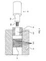
- FIG. 11is a schematic diagram illustrating assembling of an optical cable, a sealed optoelectronic isolation connection device, and a sealed cabin in prior art.
- the surface of an optical cable 101is often peeled to expose the conduit (for example, copper conduit or aluminum conduit) for transmitting electric signals in the optical cable.
- the conduit along with the optical fiber in the conductive conduitis inserted into a through hole 1021 provided in the sealed optoelectronic isolation connection device 102, and the connection part between the conduit and the through hole is sealed.
- the conduit and the optical fiberare connected to an electronic device in the sealed cabin 103, and the sealed optoelectronic isolation connection device 102 is sealed onto the sealed cabin 103.
- the sealed optoelectronic isolation connection devicein prior art only seals the copper conduit of the optical cable.
- D1discloses a waterblock assembly for an undersea optical fiber cable includes a socket with a cavity.
- a rubber plugshaped to fit into the cavity, is pierced with one or more holes for inserting an optical fiber or fibers.
- the rubber plug holding the fibers in the cavityis preloaded with an internal compressive stress which assures no leakage of fluid around or through the rubber plug throughout a range of external pressures ranging from zero to ocean bottom pressure and applied to the rubber plug.
- the present inventionprovides a sealed optoelectronic isolation connection device and a sealed cabin to overcome the defect that the reliability of the sealed optoelectronic isolation connection device in the prior art is low, and enhance the reliability of the sealed optoelectronic isolation connection device.
- the present inventionprovides a sealed optoelectronic isolation connection device, which includes: an insulation cylinder, a conduit sealing device, and an optical fiber sealing device, where the insulation cylinder is configured to insulate the conduit sealing device and the optical fiber sealing device; the conduit sealing device is provided with a conduit hole, which is configured to accommodate a conduit of the optical cable and seal the conduit; the optical fiber sealing device is provided with multiple optical fiber holes, which are configured to accommodate optical fibers of the optical cable and seal the optical fibers; and the optical fiber sealing device and the conduit sealing device are inserted in sequence into the insulation cylinder and implement sealing together with the insulation cylinder, and the optical fiber sealing device is electrically connected to the conduit sealing device; the sealed optoelectronic isolation connection device further comprises an electrode lead, the electrode lead being fixed to an end of the optical fiber sealing device distant from the optical fiber holes, and being electrically connected to the optical fiber sealing device for transmission of electrical signals transmitted in the conduit.
- the present inventionprovides a sealed cabin, which includes a sealed cabin main body, and the sealed optoelectronic isolation connection device as described above, where the sealed optoelectronic isolation connection device is fixed to the sealed cabin main body.
- the sealed optoelectronic isolation connection device and the sealed cabin provided in the present inventionseal each optical fiber of the optical cable through the optical fiber sealing device, and seal the conduit of the optical cable through the conduit sealing device, thereby separately sealing the optical fibers and the conduit of the optical cable through the sealed optoelectronic isolation connection device.
- the conduit of the optical cablebreaks, since the optical fibers are sealed by the optical fiber sealing device, the seawater will not enter along the optical fibers into the inner part of the sealed cabin sealed by the sealed optoelectronic isolation connection device after the seawater enters into the conduit. This effectively prevents the electronic devices inside the sealed cabin from being damaged. Therefore, the reliability of the sealed optoelectronic isolation connection device is enhanced.
- FIG. 1is a schematic diagram depicting a structure of the section of a sealed optoelectronic isolation connection device according to an example not forming part of the present invention.
- the sealed optoelectronic isolation connection device according to this embodimentincludes an insulation cylinder 11, an optical fiber sealing device 12, and a conduit sealing device 13.
- the insulation cylinder 11may be a cylindrical structure with a through hole, and is configured to insulate the conduit sealing device 13 and the optical fiber sealing device 12.
- the optical fiber sealing device 12is provided with multiple optical fiber holes 121, where the optical fiber holes 121 are configured to accommodate multiple optical fibers 101 of an optical cable 10 and seal the optical fibers 101.
- the conduit sealing device 13is provided with a conduit hole 131, which is configured to accommodate the conduit 102 (such as a copper or aluminum conduit) of the optical cable and seal the conduit 102.
- the optical fiber sealing device 12 and the conduit sealing device 13 3are inserted in sequence into the insulation cylinder 11 and implement sealing together with the insulation cylinder 11.
- the optical fiber sealing device 12 in the sealed optoelectronic isolation connection deviceis configured to seal the optical fibers 101 of the optical cable 10.
- Each optical fiber 101 of the optical cable 10is inserted into an optical fiber hole 121 in the optical fiber sealing device 12.
- the conduit sealing device 13 provided in this embodimentis configured to seal the conduit 102 of the optical cable 10.
- the conduit sealing device 13is located on one side of the optical fiber holes 121 in the optical fiber sealing device.
- the conduit 102 of the optical cable 10is inserted into the conduit hole 131 in the conduit sealing device 13, and therefore, the conduit 102 of the optical cable 10 can be sealed by the conduit hole 131.
- the optical fiber sealing device 12 and the conduit sealing device 13are inserted in sequence into the insulation cylinder 11 and implement sealing together with the insulation cylinder 11. In this way, by hermetically assembling the insulation cylinder 11 onto sealed devices such as the sealed cabin, hermetically connecting the optical cable 10 to an electronic device within a sealed device can be realized.
- the optical cable 10passes through in sequence the conduit sealing device 13 and the optical fiber sealing device 12, making the conduit 102 of the optical cable 10 sealed by the conduit sealing device 13, and each optical fiber 101 of the optical cable 10 sealed by the optical fiber sealing device 13.
- the sealed optoelectronic isolation connection device and the sealed cabin provided in the present inventionseal each optical fiber of the optical cable through the optical fiber sealing device, and seal the conduit of the optical cable through the conduit sealing device, thereby separately sealing the optical fibers and the conduit of the optical cable through the sealed optoelectronic isolation connection device.
- the conduit of the optical cablebreaks, since the optical fibers are sealed by the optical fiber sealing device, the seawater will not enter along the optical fibers into the inner part of the sealed cabin sealed by the sealed optoelectronic isolation connection device after the seawater enters into the conduit. This effectively prevents the electronic device inside the sealed cabin from being damaged. Therefore, the reliability of the sealed optoelectronic isolation connection device is enhanced.
- FIG. 2is a schematic diagram depicting a structure of a sealed optoelectronic isolation connection device according to an embodiment of the present invention.
- the sealed optoelectronic isolation connection device according to this embodimentbased on the above sealed optoelectronic isolation connection device provided in the first embodiment, includes an insulation cylinder 21, a conduit sealing device 23, and an optical fiber sealing device 22.
- the device according to this embodiment of the inventionfurther includes a base bushing 20.
- the insulation cylinder 21is inserted into the base bushing 20 and implements sealing together with the base bushing 20.
- the sealed optoelectronic isolation connection device provided in this embodimentis readily assembled to a sealing device such as a sealing cabin, which makes it more convenient to securely assemble the sealed optoelectronic isolation connection device provided in this embodiment.
- FIG. 3is a schematic diagram depicting a structure of the base bushing in the sealed optoelectronic isolation connection device according to the embodiment of the present invention. Further, as shown in FIG. 3 , it is a schematic diagram depicting the 3-D structure of the base bushing 20 according to this embodiment of the present invention.
- the base bushing 20 according to this embodimentis provided with a first stepped hole 201 and multiple annular grooves 202, where the first stepped hole 201 is used for connection with the insulation cylinder 21.
- FIG. 4is a schematic diagram depicting a structure of the insulation cylinder in the sealed optoelectronic isolation connection device according to the embodiment of the present invention. Referring to FIG. 4 , it is a schematic diagram depicting a 3D structure of the insulation cylinder 21.
- the insulation cylinder 21 according to this embodimenthas a stepped structure.
- the insulation cylinder 21is inserted into the first stepped hole 201.
- the insulation cylinder 21further includes a second stepped hole 211 for connection with the optical fiber sealing device 22 and the conduit sealing device 23.
- FIG. 5is a schematic diagram depicting a structure of the optical fiber sealing device in the sealed optoelectronic isolation connection device according to the embodiment of the present invention.
- FIG. 5it is a schematic diagram depicting a 3D structure of the optical fiber sealing device 22.
- the optical fiber sealing device 22is a stepped cylinder. There are multiple optical fiber holes 221 provided on one end of the stepped cylinder. There is a through hole 222 provided on the other end of the stepped cylinder. The through hole 222 is interconnected with the optical fiber holes 221.
- the conduit sealing device 23 and the optical fiber sealing device 22are inserted in sequence into the second stepped hole 211.
- each component in this embodimenthas a stepped structure.
- the insulation cylinder 21is inserted into the first stepped hole 201 of the base bushing 20, so that the stepped structure of the insulation cylinder 21 can be matched with the stepped structure of the first stepped hole 201, making the insulation cylinder 21 be fixed in the base bushing 20.
- the optical fiber sealing device 22is a stepped cylinder, one end of which is provided with optical fiber holes 221, and the other end of which is provided with a through hole 222.
- the optical fiber holes 221are interconnected with the through hole 222, so that all optical fibers of the optical cable are aggregated in the through hole 222 after the optical fibers pass through the optical fiber hole 221, making it convenient for the optical fibers passing through the optical fiber sealing device 22 to connect to other devices.
- the optical fiber sealing device 22 and the conduit sealing device 23are inserted in sequence into the second stepped hole 211, and the stepped structure of the optical fiber sealing device 22 is matched with the second stepped hole 211, so that the optical fiber sealing device 22 and the conduit sealing device 23 are securely fixed in the insulation cylinder 21.
- the end of the optical fiber sealing device 22 on which the optical fiber holes 221 are providedis threadedly connected to the conduit sealing device.
- the end of the optical fiber sealing device 22 on which the optical fiber holes 221 are providedcan be configured with screw threads, and the conduit sealing device 23 can be configured with a threaded hole, so that the optical fiber sealing device 22 and the conduit sealing device 23 can be threadedly connected to each other, which makes it convenient to insert the optical fiber sealing device 22 along with the conduit sealing device 23 into the second stepped hole 211.
- the connection part between themis more hermetic, making it more conducive to enhancing the reliability of the sealed optoelectronic isolation connection device provided in this embodiment.
- the optical fiber sealing device 22extends beyond the end of the insulation cylinder 21 so that the optical fiber sealing device 22 can be threadedly connected to screw nuts 28, which lean against the insulation cylinder 21.
- the optical fiber sealing device 22is securely fixed to the insulation cylinder 21 through the screw nuts 28, so that the insulation cylinder 21, the optical fiber sealing device 22, and the conduit sealing device 23 are first assembled, and then they are placed into the base bushing 20. This can effectively simplify the process of assembling the sealed optoelectronic isolation connection device according to this embodiment.
- the sealed optoelectronic isolation connection deviceby providing a base bushing and inserting the insulation cylinder into the base bushing, the sealed optoelectronic isolation connection device according to this embodiment can be more readily assembled onto a sealed device such as a sealed cabin, so that the sealed optoelectronic isolation connection device according to this embodiment can be more readily and securely assembled and used.
- a sealed devicesuch as a sealed cabin
- the optical fiber sealing device and the conduit sealing devicecan be more readily assembled into the insulation cylinder, and the connection part between the optical fiber sealing device and the conduit sealing device is more hermetical, which more effectively enhances the reliability of the sealed optoelectronic isolation connection device provided in this embodiment.
- the sealed optoelectronic isolation connection devicefurther includes a curved protective casing 24.
- the curved protective casing 24is inserted into the through hole 222 of the optical fiber sealing device 22, and is configured to enclose the outer part of the optical fibers passing through the optical fiber sealing device 22.
- FIG. 7is a schematic diagram depicting a structure of a curved protective casing in the sealed optoelectronic isolation connection device according to the embodiment of the present invention.
- FIG. 7it is a schematic diagram depicting a 3D structure of the curved protective casing 24 according to this embodiment.
- An end 241 of the curved protective casing 24is inserted into the through hole 222 of the optical fiber sealing 22.
- the curved protective casing 24encloses the outer part of the optical fibers passing through the optical fiber sealing device 22. This can effectively prevent the optical fibers from being damaged by other components and prevent the optical fibers from being damaged due to an excessive bending angle at the time of assembling the sealed optoelectronic isolation connection device according to this embodiment. Therefore, the optical fibers can be effectively protected.
- the optical fiber sealing device 22can be electrically connected to the conduit sealing device 23 in the present embodiment.
- the sealed optoelectronic isolation connection devicemay further include an electrode lead 25.
- the electrode lead 25is fixed to an end of the optical fiber sealing device 22 distant from the optical fiber holes 221, and is electrically connected to the optical fiber sealing device 22.
- the electrode lead 25is configured to transmit electrical signals transmitted in the conduit (such as a copper conduit) of the optical cable.
- the optical fibers of the optical cableare used for transmitting optical signals, whereas the conduit of the optical cable is used for transmitting electrical signals.
- the optical fiber sealing device 22is electrically connected to the conduit sealing device 23.
- the electrode lead 25is electrically connected to the optical fiber sealing device 22. This can make the electrical signals transmitted in the conduit of the optical cable pass through in sequence the conduit sealing device 23 and the optical fiber sealing device 22 to the electrode lead 25.
- the electrode lead 25is connected to the electronic device in a sealed device such as the sealed cabin. Therefore, by enabling the electrical signals to pass through in sequence the conduit of the optical cable, the conduit sealing device 23, the optical fiber sealing device 22, and the electrode lead 25, the electrical signals can ultimately be transmitted to the electronic device in a sealed device such as the sealed cabin.
- the sealed optoelectronic isolation connection devicemay further include a locking block 26.
- the locking block 26is connected to the conduit sealing device 23 via screw bolts (not shown in this figure), and is configured to fix the conduit to the conduit sealing device 23.
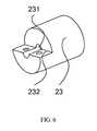
- FIG. 6is a schematic diagram depicting a structure of the conduit sealing device in the sealed optoelectronic isolation connection device provided in the second embodiment of the present invention. Specifically, referring to FIG. 6 , it is a schematic diagram depicting a 3D structure of the conduit sealing device according to this embodiment.
- the conduit sealing device 23is provided with a conduit hole 231 and a notch 232.
- FIG. 8is a schematic diagram depicting assembly of the locking block and the conduit sealing device of the sealed optoelectronic isolation connection device provided in the second embodiment of the present invention. Specifically, referring to FIG. 8 , it is a schematic diagram depicting assembly of the locking block 26 and the conduit sealing device 23 according to this embodiment.
- the locking block 26In installation, the locking block 26 is placed at the notch 232, and by inserting screw bolts into installation holes 261 provided on the locking block 26 and threaded holes 233 of the conduit sealing device 23, the screw bolts are made threadedly connected to the threaded holes 233, so that the locking block 26 is fixed onto the conduit sealing device 23.
- the conduitis securely fixed onto the conduit sealing device 23 using the locking block 26, thereby preventing the conduit from escaping out of the conduit hole 231. This effectively enhances the reliability of the sealed optoelectronic isolation connection device provided in this embodiment.
- the sealed optoelectronic isolation connection devicecan effectively protect the optical fibers and prevent them from being damaged.
- the electrical signals transmitted in the conduitcan pass through in sequence the conduit sealing device and the optical fiber sealing device and enter into the electrode lead. Therefore, by connecting the electrode lead to the electronic device in a sealing device such as the sealing cabin, transmission of the electrical signals to the electronic device is realized.
- the locking blockafter inserting the conduit into the conduit hole, the conduit can be securely fixed onto the conduit sealing device through the locking block. In this way, the conduit can be prevented from escaping out of the conduit hole. This effectively enhances the reliability of the sealed optoelectronic isolation connection device provided in this embodiment.
- the sealed optoelectronic isolation connection devicefurther includes a casted protection layer 27.
- the casted protection layer 27is fixed onto an end of the base bushing 20 close to the conduit sealing device 23, and is configured to seal the base bushing 20, after the optical cable is inserted into the sealed optoelectronic isolation connection device according to this embodiment.
- the end of the base bushing 20 according to this embodiment close to the conduit sealing device 23is fixed with the casted protection layer 27.
- the casted protection layer 27can be made of high molecular material such as polyethylene and is fixed onto the base bushing 20 by casting.
- the casted protection layer 27can seal the end surface of the base bushing in the optical fiber insertion direction, thereby sealing the optical fiber sealing device 22 and the conduit sealing device 23 in the base bushing 20, and improving the sealing performance of the sealed optoelectronic isolation connection device according to this embodiment.
- FIG. 9is a schematic diagram depicting a structure of an external pressure ring in the sealed cabin provided in an embodiment of the present invention.
- the sealed optoelectronic isolation connection devicemay further include an external pressure ring 271, which fixedly connects the casted protection layer 27 and the base bushing 20 in sequence via a screw bolt 272. By fixedly connecting in sequence the casted protection layer 27 and the base bushing 20 via the screw bolt, the external pressure ring 271 can more securely fix the casted protection layer 27 to the base bushing 20.
- the sealed optoelectronic isolation connection deviceby casting the casted protection layer onto the base bushing after the optical cable is assembled, can seal the end surface of the base bushing in the optical fiber insertion direction through the casted protection layer, so that the optical fiber sealing device and the conduit sealing device are sealed in the base bushing, which enables the sealed optoelectronic isolation connection device according to this embodiment to more securely seal the optical cable, thereby more effectively enhancing the reliability of the sealed optoelectronic isolation connection device provided in this embodiment.
- the sealed optoelectronic isolation connection devicemay have many sealing modes.
- Mode 1sealing via a sealing ring.
- a sealing ring(not shown in the figures) may be provided between the optical fiber sealing device 22 and the insulation cylinder 21 in this embodiment; and/or a sealing ring may be provided between the conduit sealing device 23 and the insulation cylinder 21; a sealing ring may be provided between the insulation cylinder 21 and the base bushing 20; multiple grooves (not shown in the figures) for placing the sealing rings may be provided outside the base bushing 20.
- Mode 2sealing by welding.
- the optical fiber sealing device 22 and the conduit sealing device 23are separately welded to the insulation cylinder 21, and the insulation cylinder 21 is welded to the base bushing 20. Specifically, by welding together each sealed part, each sealed part can be securely sealed.
- each sealed part in the sealed optoelectronic isolation connection device according to this embodimentcan be sealed with a sealing ring, or can be sealed by welding, or can be sealed both through the sealing ring and by welding.
- FIG. 10is a schematic diagram depicting a structure of the sealed cabin provided in the embodiment of the present invention.
- the sealed cabin according to this embodimentincludes a sealed cabin main body 91, and further includes a sealed optoelectronic isolation connection device 92.
- the sealed optoelectronic isolation connection device 92 in this embodimentmay adopt the sealed optoelectronic isolation connection device provided in the present invention.
- the sealed optoelectronic isolation connection device 92is fixed onto the sealed cabin 91.
- the specific structure of the sealed optoelectronic isolation connection device 92 in this embodimentcan be seen in the embodiment of the sealed optoelectronic isolation connection device and figures 1-8 . Therefore, the details are not described herein.
- An electronic deviceis deployed in the sealed cabin main body 91 according to this embodiment.
- the opening of the sealed cabin main body 91is sealed by the sealed optoelectronic isolation connection device, the optical cable passes through the sealed optoelectronic isolation connection device 92 and connects to the electronic device in the sealed cabin main body 91.
- the sealed optoelectronic isolation connection device 92seals the optical cable and prevents water from entering into the sealed cabin main body 91.
- the sealed cabinseals each optical fiber of the optical cable by providing an optical fiber sealing device, and seals the conduit in the optical fiber using a conduit sealing device, thereby sealing the optical fibers and the conduit of the optical cable with the sealed optoelectronic isolation connection device.
- the conduit of the optical cablebreaks, as the optical fibers are sealed by the optical fiber sealing device, water will not enter along the optical fibers into the inner part of the sealed cabin sealed by the sealed optoelectronic isolation connection device. This effectively prevents the electronic device within the sealed cabin from being damaged. Therefore, the reliability of the sealed optoelectronic isolation connection device is enhanced.
Landscapes
- Physics & Mathematics (AREA)
- General Physics & Mathematics (AREA)
- Optics & Photonics (AREA)
- Light Guides In General And Applications Therefor (AREA)
- Mechanical Coupling Of Light Guides (AREA)
- Cable Accessories (AREA)
Description
- The present invention relates to the technical field of electronics, and in particular, to a sealed optoelectronic isolation connection device and a sealed cabin.
- At present, with high transmission efficiency, the optical cable is widely used in the communication industry. As required by information transmission, submarine optical fiber cables need to be installed in some application scenarios. Usually it is necessary to connect an optical cable operating in the submarine environment to an electronic device in a sealed cabin via a sealed optoelectronic isolation connection device. The sealed optoelectronic isolation connection device is a connection component for the entry of the optical cable into the sealed cabin, is installed on the outer wall of the sealed cabin, and the outer part of the sealed optoelectronic isolation connection device directly contacts the seawater. After passing through the sealed optoelectronic isolation connection device, the optical cable can connect to the electronic device in the sealed cabin. By sealing the sealed cabin using the sealed optoelectronic isolation connection device, damages that may be made by high-pressure seawater to the connection between the optical cable and the electronic device can be prevented.
FIG. 11 is a schematic diagram illustrating assembling of an optical cable, a sealed optoelectronic isolation connection device, and a sealed cabin in prior art. As shown inFIG. 11 , for a sealed optoelectronicisolation connection device 102 in prior art, the surface of anoptical cable 101 is often peeled to expose the conduit (for example, copper conduit or aluminum conduit) for transmitting electric signals in the optical cable. Then, the conduit along with the optical fiber in the conductive conduit is inserted into athrough hole 1021 provided in the sealed optoelectronicisolation connection device 102, and the connection part between the conduit and the through hole is sealed. Finally, the conduit and the optical fiber are connected to an electronic device in the sealedcabin 103, and the sealed optoelectronicisolation connection device 102 is sealed onto the sealedcabin 103.- In the process of implementing the present invention, the inventor finds that the sealed optoelectronic isolation connection device in prior art only seals the copper conduit of the optical cable. When the copper conduit outside the sealed optoelectronic isolation connection device breaks, the seawater will enter into the sealed cabin along the optical fiber in the conduit and damage the electronic device in the sealed cabin. Therefore, the reliability of the sealed optoelectronic isolation connection device in the prior art is low.
- D1 (
US 4834479 ) discloses a waterblock assembly for an undersea optical fiber cable includes a socket with a cavity. A rubber plug, shaped to fit into the cavity, is pierced with one or more holes for inserting an optical fiber or fibers. The rubber plug holding the fibers in the cavity is preloaded with an internal compressive stress which assures no leakage of fluid around or through the rubber plug throughout a range of external pressures ranging from zero to ocean bottom pressure and applied to the rubber plug. - The present invention provides a sealed optoelectronic isolation connection device and a sealed cabin to overcome the defect that the reliability of the sealed optoelectronic isolation connection device in the prior art is low, and enhance the reliability of the sealed optoelectronic isolation connection device.
- The present invention provides a sealed optoelectronic isolation connection device, which includes: an insulation cylinder, a conduit sealing device, and an optical fiber sealing device, where the insulation cylinder is configured to insulate the conduit sealing device and the optical fiber sealing device; the conduit sealing device is provided with a conduit hole, which is configured to accommodate a conduit of the optical cable and seal the conduit; the optical fiber sealing device is provided with multiple optical fiber holes, which are configured to accommodate optical fibers of the optical cable and seal the optical fibers; and the optical fiber sealing device and the conduit sealing device are inserted in sequence into the insulation cylinder and implement sealing together with the insulation cylinder, and the optical fiber sealing device is electrically connected to the conduit sealing device; the sealed optoelectronic isolation connection device further comprises an electrode lead, the electrode lead being fixed to an end of the optical fiber sealing device distant from the optical fiber holes, and being electrically connected to the optical fiber sealing device for transmission of electrical signals transmitted in the conduit.
- The present invention provides a sealed cabin, which includes a sealed cabin main body, and the sealed optoelectronic isolation connection device as described above, where the sealed optoelectronic isolation connection device is fixed to the sealed cabin main body.
- The sealed optoelectronic isolation connection device and the sealed cabin provided in the present invention seal each optical fiber of the optical cable through the optical fiber sealing device, and seal the conduit of the optical cable through the conduit sealing device, thereby separately sealing the optical fibers and the conduit of the optical cable through the sealed optoelectronic isolation connection device. When the conduit of the optical cable breaks, since the optical fibers are sealed by the optical fiber sealing device, the seawater will not enter along the optical fibers into the inner part of the sealed cabin sealed by the sealed optoelectronic isolation connection device after the seawater enters into the conduit. This effectively prevents the electronic devices inside the sealed cabin from being damaged. Therefore, the reliability of the sealed optoelectronic isolation connection device is enhanced.
- To more clearly illustrate the embodiments of the present invention or the technical solutions in the prior art, the following briefly describes the accompanying drawings to be used in describing the embodiments and the prior art. Obviously, the accompanying drawings are merely some embodiments of the present invention. For those of ordinary skill in the art, other accompanying drawings may be obtained without creative efforts according to these accompanying drawings.
FIG. 1 is a schematic diagram depicting a structure of the section of a sealed optoelectronic isolation connection device according to a an example not forming part of the present invention;FIG. 2 is a schematic diagram depicting a structure of a sealed optoelectronic isolation connection device according to a second embodiment of the present invention;FIG. 3 is a schematic diagram depicting a structure of a base bushing in the sealed optoelectronic isolation connection device according to an embodiment of the present invention;FIG. 4 is a schematic diagram depicting a structure of an insulation cylinder in the sealed optoelectronic isolation connection device according to an embodiment of the present invention;FIG. 5 is a schematic diagram depicting a structure of an optical fiber sealing device in the sealed optoelectronic isolation connection device according to an embodiment of the present invention;FIG. 6 is a schematic diagram depicting a structure of a conduit sealing device in the sealed optoelectronic isolation connection device according to an embodiment of the present invention;FIG. 7 is a schematic diagram depicting a structure of a curved protective casing in the sealed optoelectronic isolation connection device according to an embodiment of the present invention;FIG. 8 is a schematic diagram depicting assembly of a locking block and the conduit sealing device in the sealed optoelectronic isolation connection device according to an embodiment of the present invention;FIG. 9 is a schematic diagram depicting a structure of an external pressure ring in the sealed cabin provided in the present invention;FIG. 10 is a schematic diagram depicting a structure of the sealed cabin according to an embodiment of the present invention; andFIG. 11 is a schematic diagram showing assembly of an optical cable, a sealed optoelectronic isolation connection device, and a sealed cabin in the prior art.- To make the objectives, technical solutions, and advantages of embodiments of the present invention more clear, the following describes the technical solutions provided in embodiments of the present invention clearly and with reference to the accompanying drawings. Obviously, the embodiments as shown are only a part, but not all, of the embodiments of the present invention. All other embodiments made by those of ordinary skill in the art according to the embodiments of the present invention herein without creative efforts shall fall within the scope of the present invention.
FIG. 1 is a schematic diagram depicting a structure of the section of a sealed optoelectronic isolation connection device according to an example not forming part of the present invention. As shown inFIG. 1 , the sealed optoelectronic isolation connection device according to this embodiment includes aninsulation cylinder 11, an opticalfiber sealing device 12, and aconduit sealing device 13.- In this example, the
insulation cylinder 11 may be a cylindrical structure with a through hole, and is configured to insulate theconduit sealing device 13 and the opticalfiber sealing device 12. - The optical
fiber sealing device 12 is provided with multipleoptical fiber holes 121, where theoptical fiber holes 121 are configured to accommodate multipleoptical fibers 101 of an optical cable 10 and seal theoptical fibers 101. - The
conduit sealing device 13 is provided with aconduit hole 131, which is configured to accommodate the conduit 102 (such as a copper or aluminum conduit) of the optical cable and seal the conduit 102.The opticalfiber sealing device 12 and theconduit sealing device 13 3 are inserted in sequence into theinsulation cylinder 11 and implement sealing together with theinsulation cylinder 11. - Specifically, the optical
fiber sealing device 12 in the sealed optoelectronic isolation connection device according to this embodiment is configured to seal theoptical fibers 101 of the optical cable 10. Eachoptical fiber 101 of the optical cable 10 is inserted into anoptical fiber hole 121 in the opticalfiber sealing device 12. In this way, eachoptical fiber 101 of the optical cable 10 can be sealed by eachoptical fiber hole 121. In addition, theconduit sealing device 13 provided in this embodiment is configured to seal theconduit 102 of the optical cable 10. Theconduit sealing device 13 is located on one side of theoptical fiber holes 121 in the optical fiber sealing device. Theconduit 102 of the optical cable 10 is inserted into theconduit hole 131 in theconduit sealing device 13, and therefore, theconduit 102 of the optical cable 10 can be sealed by theconduit hole 131. The opticalfiber sealing device 12 and theconduit sealing device 13 according to this embodiment are inserted in sequence into theinsulation cylinder 11 and implement sealing together with theinsulation cylinder 11. In this way, by hermetically assembling theinsulation cylinder 11 onto sealed devices such as the sealed cabin, hermetically connecting the optical cable 10 to an electronic device within a sealed device can be realized. In actual practice, the optical cable 10 passes through in sequence theconduit sealing device 13 and the opticalfiber sealing device 12, making theconduit 102 of the optical cable 10 sealed by theconduit sealing device 13, and eachoptical fiber 101 of the optical cable 10 sealed by the opticalfiber sealing device 13. - The sealed optoelectronic isolation connection device and the sealed cabin provided in the present invention seal each optical fiber of the optical cable through the optical fiber sealing device, and seal the conduit of the optical cable through the conduit sealing device, thereby separately sealing the optical fibers and the conduit of the optical cable through the sealed optoelectronic isolation connection device. When the conduit of the optical cable breaks, since the optical fibers are sealed by the optical fiber sealing device, the seawater will not enter along the optical fibers into the inner part of the sealed cabin sealed by the sealed optoelectronic isolation connection device after the seawater enters into the conduit. This effectively prevents the electronic device inside the sealed cabin from being damaged. Therefore, the reliability of the sealed optoelectronic isolation connection device is enhanced.
FIG. 2 is a schematic diagram depicting a structure of a sealed optoelectronic isolation connection device according to an embodiment of the present invention. As shown inFIG. 2 , the sealed optoelectronic isolation connection device according to this embodiment, based on the above sealed optoelectronic isolation connection device provided in the first embodiment, includes aninsulation cylinder 21, aconduit sealing device 23, and an opticalfiber sealing device 22. In addition, the device according to this embodiment of the invention further includes abase bushing 20.- The
insulation cylinder 21 is inserted into thebase bushing 20 and implements sealing together with thebase bushing 20. In this way, through thebase bushing 20, the sealed optoelectronic isolation connection device provided in this embodiment is readily assembled to a sealing device such as a sealing cabin, which makes it more convenient to securely assemble the sealed optoelectronic isolation connection device provided in this embodiment. FIG. 3 is a schematic diagram depicting a structure of the base bushing in the sealed optoelectronic isolation connection device according to the embodiment of the present invention. Further, as shown inFIG. 3 , it is a schematic diagram depicting the 3-D structure of thebase bushing 20 according to this embodiment of the present invention. Thebase bushing 20 according to this embodiment is provided with a first steppedhole 201 and multipleannular grooves 202, where the first steppedhole 201 is used for connection with theinsulation cylinder 21.FIG. 4 is a schematic diagram depicting a structure of the insulation cylinder in the sealed optoelectronic isolation connection device according to the embodiment of the present invention. Referring toFIG. 4 , it is a schematic diagram depicting a 3D structure of theinsulation cylinder 21. Theinsulation cylinder 21 according to this embodiment has a stepped structure. Theinsulation cylinder 21 is inserted into the first steppedhole 201. Theinsulation cylinder 21 further includes a second steppedhole 211 for connection with the opticalfiber sealing device 22 and theconduit sealing device 23.FIG. 5 is a schematic diagram depicting a structure of the optical fiber sealing device in the sealed optoelectronic isolation connection device according to the embodiment of the present invention. Referring toFIG. 5 , it is a schematic diagram depicting a 3D structure of the opticalfiber sealing device 22. The opticalfiber sealing device 22 is a stepped cylinder. There are multiple optical fiber holes 221 provided on one end of the stepped cylinder. There is a throughhole 222 provided on the other end of the stepped cylinder. The throughhole 222 is interconnected with the optical fiber holes 221.- In this embodiment of the invention, the
conduit sealing device 23 and the opticalfiber sealing device 22 are inserted in sequence into the second steppedhole 211. Specifically, to reliably and securely connect all components of the sealed optoelectronic isolation connection device of the present invention to each other, each component in this embodiment has a stepped structure. Theinsulation cylinder 21 is inserted into the first steppedhole 201 of thebase bushing 20, so that the stepped structure of theinsulation cylinder 21 can be matched with the stepped structure of the first steppedhole 201, making theinsulation cylinder 21 be fixed in thebase bushing 20. In addition, the opticalfiber sealing device 22 is a stepped cylinder, one end of which is provided with optical fiber holes 221, and the other end of which is provided with a throughhole 222. The optical fiber holes 221 are interconnected with the throughhole 222, so that all optical fibers of the optical cable are aggregated in the throughhole 222 after the optical fibers pass through theoptical fiber hole 221, making it convenient for the optical fibers passing through the opticalfiber sealing device 22 to connect to other devices. Finally, the opticalfiber sealing device 22 and theconduit sealing device 23 are inserted in sequence into the second steppedhole 211, and the stepped structure of the opticalfiber sealing device 22 is matched with the second steppedhole 211, so that the opticalfiber sealing device 22 and theconduit sealing device 23 are securely fixed in theinsulation cylinder 21. - To conveniently insert the optical
fiber sealing device 22 and theconduit sealing device 23 into the second steppedhole 211, the end of the opticalfiber sealing device 22 on which the optical fiber holes 221 are provided, is threadedly connected to the conduit sealing device. Specifically, the end of the opticalfiber sealing device 22 on which the optical fiber holes 221 are provided can be configured with screw threads, and theconduit sealing device 23 can be configured with a threaded hole, so that the opticalfiber sealing device 22 and theconduit sealing device 23 can be threadedly connected to each other, which makes it convenient to insert the opticalfiber sealing device 22 along with theconduit sealing device 23 into the second steppedhole 211. Further, since the opticalfiber sealing device 22 and the conduit sealing device are threadedly connected to each other, the connection part between them is more hermetic, making it more conducive to enhancing the reliability of the sealed optoelectronic isolation connection device provided in this embodiment. - In addition, the optical
fiber sealing device 22 according to this embodiment extends beyond the end of theinsulation cylinder 21 so that the opticalfiber sealing device 22 can be threadedly connected to screwnuts 28, which lean against theinsulation cylinder 21. Specifically, after matching the outer stepped structure of the opticalfiber sealing device 22 with the second steppedhole 211, the opticalfiber sealing device 22 is securely fixed to theinsulation cylinder 21 through thescrew nuts 28, so that theinsulation cylinder 21, the opticalfiber sealing device 22, and theconduit sealing device 23 are first assembled, and then they are placed into thebase bushing 20. This can effectively simplify the process of assembling the sealed optoelectronic isolation connection device according to this embodiment. - In the sealed optoelectronic isolation connection device according to this embodiment, by providing a base bushing and inserting the insulation cylinder into the base bushing, the sealed optoelectronic isolation connection device according to this embodiment can be more readily assembled onto a sealed device such as a sealed cabin, so that the sealed optoelectronic isolation connection device according to this embodiment can be more readily and securely assembled and used. By configuring all components in the embodiment as a stepped structure, all components can be more accurately and securely assembled. In addition, by threadedly connecting the optical fiber sealing device to the conduit sealing device, the optical fiber sealing device and the conduit sealing device can be more readily assembled into the insulation cylinder, and the connection part between the optical fiber sealing device and the conduit sealing device is more hermetical, which more effectively enhances the reliability of the sealed optoelectronic isolation connection device provided in this embodiment.
- Based on the above technical solutions, optionally, referring to
FIG. 2 , the sealed optoelectronic isolation connection device according to this embodiment further includes a curvedprotective casing 24. The curvedprotective casing 24 is inserted into the throughhole 222 of the opticalfiber sealing device 22, and is configured to enclose the outer part of the optical fibers passing through the opticalfiber sealing device 22. FIG. 7 is a schematic diagram depicting a structure of a curved protective casing in the sealed optoelectronic isolation connection device according to the embodiment of the present invention. Referring toFIG. 7 , it is a schematic diagram depicting a 3D structure of the curvedprotective casing 24 according to this embodiment. Anend 241 of the curvedprotective casing 24 is inserted into the throughhole 222 of the optical fiber sealing 22. The curvedprotective casing 24 encloses the outer part of the optical fibers passing through the opticalfiber sealing device 22. This can effectively prevent the optical fibers from being damaged by other components and prevent the optical fibers from being damaged due to an excessive bending angle at the time of assembling the sealed optoelectronic isolation connection device according to this embodiment. Therefore, the optical fibers can be effectively protected.- Further, the optical
fiber sealing device 22 can be electrically connected to theconduit sealing device 23 in the present embodiment. Referring toFIG. 2 , the sealed optoelectronic isolation connection device according to this embodiment may further include anelectrode lead 25. Theelectrode lead 25 is fixed to an end of the opticalfiber sealing device 22 distant from the optical fiber holes 221, and is electrically connected to the opticalfiber sealing device 22. Theelectrode lead 25 is configured to transmit electrical signals transmitted in the conduit (such as a copper conduit) of the optical cable. Specifically, the optical fibers of the optical cable are used for transmitting optical signals, whereas the conduit of the optical cable is used for transmitting electrical signals. To readily transmit electrical signals transmitted in the conduit through the sealed optoelectronic isolation connection device according to this embodiment, the opticalfiber sealing device 22 is electrically connected to theconduit sealing device 23. Moreover, theelectrode lead 25 is electrically connected to the opticalfiber sealing device 22. This can make the electrical signals transmitted in the conduit of the optical cable pass through in sequence theconduit sealing device 23 and the opticalfiber sealing device 22 to theelectrode lead 25. In this way, by connecting theelectrode lead 25 to the electronic device in a sealed device such as the sealed cabin, transmission of electrical signals to the electronic device can be realized. Therefore, by enabling the electrical signals to pass through in sequence the conduit of the optical cable, theconduit sealing device 23, the opticalfiber sealing device 22, and theelectrode lead 25, the electrical signals can ultimately be transmitted to the electronic device in a sealed device such as the sealed cabin. - As shown in
FIG. 2 , in addition, the sealed optoelectronic isolation connection device according to this embodiment may further include alocking block 26. The lockingblock 26 is connected to theconduit sealing device 23 via screw bolts (not shown in this figure), and is configured to fix the conduit to theconduit sealing device 23.FIG. 6 is a schematic diagram depicting a structure of the conduit sealing device in the sealed optoelectronic isolation connection device provided in the second embodiment of the present invention. Specifically, referring toFIG. 6 , it is a schematic diagram depicting a 3D structure of the conduit sealing device according to this embodiment. Theconduit sealing device 23 is provided with aconduit hole 231 and anotch 232. Theconduit hole 231 is configured to accommodate the conduit of the optical cable, and thenotch 232 is configured to place the lockingblock 26, to securely fix the conduit of the optical cable to theconduit sealing device 23 through the lockingblock 26.FIG. 8 is a schematic diagram depicting assembly of the locking block and the conduit sealing device of the sealed optoelectronic isolation connection device provided in the second embodiment of the present invention. Specifically, referring toFIG. 8 , it is a schematic diagram depicting assembly of the lockingblock 26 and theconduit sealing device 23 according to this embodiment. In installation, the lockingblock 26 is placed at thenotch 232, and by inserting screw bolts intoinstallation holes 261 provided on the lockingblock 26 and threadedholes 233 of theconduit sealing device 23, the screw bolts are made threadedly connected to the threadedholes 233, so that the lockingblock 26 is fixed onto theconduit sealing device 23. When in use, after the conduit of the optical cable is inserted into theconduit hole 231 of theconduit sealing device 23, by fixing the lockingblock 26 onto theconduit sealing device 23 through the screw bolts, the conduit is securely fixed onto theconduit sealing device 23 using thelocking block 26, thereby preventing the conduit from escaping out of theconduit hole 231. This effectively enhances the reliability of the sealed optoelectronic isolation connection device provided in this embodiment. - By providing the curved protective casing, the sealed optoelectronic isolation connection device according to this embodiment can effectively protect the optical fibers and prevent them from being damaged. By providing the electrode lead, the electrical signals transmitted in the conduit can pass through in sequence the conduit sealing device and the optical fiber sealing device and enter into the electrode lead. Therefore, by connecting the electrode lead to the electronic device in a sealing device such as the sealing cabin, transmission of the electrical signals to the electronic device is realized. By providing the locking block, after inserting the conduit into the conduit hole, the conduit can be securely fixed onto the conduit sealing device through the locking block. In this way, the conduit can be prevented from escaping out of the conduit hole. This effectively enhances the reliability of the sealed optoelectronic isolation connection device provided in this embodiment.
- Referring to
FIG. 2 , based on the above technical solutions, optionally, the sealed optoelectronic isolation connection device according to this embodiment further includes acasted protection layer 27. Thecasted protection layer 27 is fixed onto an end of thebase bushing 20 close to theconduit sealing device 23, and is configured to seal thebase bushing 20, after the optical cable is inserted into the sealed optoelectronic isolation connection device according to this embodiment. - Specifically, after the optical fibers of the optical cable are inserted into the optical fiber holes 221 and the conduit is inserted into the
conduit hole 231, the end of thebase bushing 20 according to this embodiment close to theconduit sealing device 23 is fixed with thecasted protection layer 27. Thecasted protection layer 27 can be made of high molecular material such as polyethylene and is fixed onto thebase bushing 20 by casting. Thecasted protection layer 27 can seal the end surface of the base bushing in the optical fiber insertion direction, thereby sealing the opticalfiber sealing device 22 and theconduit sealing device 23 in thebase bushing 20, and improving the sealing performance of the sealed optoelectronic isolation connection device according to this embodiment. To more securely fix thecasted protection layer 27 onto thebase bushing 20, multipleannular grooves 202 may be provided on the part where thebase bushing 20 and thecasted protection layer 27 are connected. By providingannular grooves 202 on thebase bushing 20, the casting material can flow into theannular grooves 202 in the process of casting theprotection layer 27, enabling thecasted protection layer 27 to be more securely fixed onto thebase bushing 20.FIG. 9 is a schematic diagram depicting a structure of an external pressure ring in the sealed cabin provided in an embodiment of the present invention. Referring toFIG. 9 , the sealed optoelectronic isolation connection device according to this embodiment may further include anexternal pressure ring 271, which fixedly connects thecasted protection layer 27 and thebase bushing 20 in sequence via ascrew bolt 272. By fixedly connecting in sequence thecasted protection layer 27 and thebase bushing 20 via the screw bolt, theexternal pressure ring 271 can more securely fix thecasted protection layer 27 to thebase bushing 20. - The sealed optoelectronic isolation connection device according to this embodiment, by casting the casted protection layer onto the base bushing after the optical cable is assembled, can seal the end surface of the base bushing in the optical fiber insertion direction through the casted protection layer, so that the optical fiber sealing device and the conduit sealing device are sealed in the base bushing, which enables the sealed optoelectronic isolation connection device according to this embodiment to more securely seal the optical cable, thereby more effectively enhancing the reliability of the sealed optoelectronic isolation connection device provided in this embodiment.
- Based on the above technical solution, optionally, the sealed optoelectronic isolation connection device according to this embodiment may have many sealing modes.
- Mode 1: sealing via a sealing ring. A sealing ring (not shown in the figures) may be provided between the optical
fiber sealing device 22 and theinsulation cylinder 21 in this embodiment; and/or a sealing ring may be provided between theconduit sealing device 23 and theinsulation cylinder 21; a sealing ring may be provided between theinsulation cylinder 21 and thebase bushing 20; multiple grooves (not shown in the figures) for placing the sealing rings may be provided outside thebase bushing 20. Specifically, by providing sealing rings at each sealed part of the sealed optoelectronic isolation connection device according to this embodiment, all sealed parts can be sealed by the sealing rings. - Mode 2: sealing by welding. The optical
fiber sealing device 22 and theconduit sealing device 23 are separately welded to theinsulation cylinder 21, and theinsulation cylinder 21 is welded to thebase bushing 20. Specifically, by welding together each sealed part, each sealed part can be securely sealed. - Mode 3: using both the sealing rings and welding. Specifically, each sealed part in the sealed optoelectronic isolation connection device according to this embodiment can be sealed with a sealing ring, or can be sealed by welding, or can be sealed both through the sealing ring and by welding.
FIG. 10 is a schematic diagram depicting a structure of the sealed cabin provided in the embodiment of the present invention. As shown inFIG. 10 , the sealed cabin according to this embodiment includes a sealed cabinmain body 91, and further includes a sealed optoelectronicisolation connection device 92. The sealed optoelectronicisolation connection device 92 in this embodiment may adopt the sealed optoelectronic isolation connection device provided in the present invention. The sealed optoelectronicisolation connection device 92 is fixed onto the sealedcabin 91.- Specifically, the specific structure of the sealed optoelectronic
isolation connection device 92 in this embodiment can be seen in the embodiment of the sealed optoelectronic isolation connection device andfigures 1-8 . Therefore, the details are not described herein. An electronic device is deployed in the sealed cabinmain body 91 according to this embodiment. To enable the optical cable to securely connect to the electronic device in the sealed cabinmain body 91 under a sealed condition, the opening of the sealed cabinmain body 91 is sealed by the sealed optoelectronic isolation connection device, the optical cable passes through the sealed optoelectronicisolation connection device 92 and connects to the electronic device in the sealed cabinmain body 91. The sealed optoelectronicisolation connection device 92 seals the optical cable and prevents water from entering into the sealed cabinmain body 91. - The sealed cabin according to this embodiment seals each optical fiber of the optical cable by providing an optical fiber sealing device, and seals the conduit in the optical fiber using a conduit sealing device, thereby sealing the optical fibers and the conduit of the optical cable with the sealed optoelectronic isolation connection device. When the conduit of the optical cable breaks, as the optical fibers are sealed by the optical fiber sealing device, water will not enter along the optical fibers into the inner part of the sealed cabin sealed by the sealed optoelectronic isolation connection device. This effectively prevents the electronic device within the sealed cabin from being damaged. Therefore, the reliability of the sealed optoelectronic isolation connection device is enhanced.
- Finally, it should be noted that the above embodiments are merely used for illustrating the technical solutions of the present invention, but not to limit the present invention. Though the present invention has been described in detail with reference to the foregoing embodiments, those of ordinary skill in the art should understand that modifications can still be made to the technical solutions as recited in foregoing embodiments, or equivalent replacements can be made to part of the technical features thereof. However, these modifications or replacement will not make the gist of corresponding technical solutions depart from the scope of each technical solution of the present invention.
Claims (9)
- A sealed optoelectronic isolation connection device, comprising: an insulation cylinder (21), a conduit sealing device (23), and an optical fiber sealing device (22):the insulation cylinder (21) is configured to insulate the conduit sealing device and the optical fiber sealing device;the conduit sealing device (23) is provided with a conduit hole for accommodating a conduit of an optical cable and sealing the conduit;the optical fiber sealing device is provided with multiple optical fiber holes (221) for accommodating optical fibers of the optical cable and sealing the optical fibers;the optical fiber sealing device (22) and the conduit sealing device (23) are inserted in sequence into the insulation cylinder and implement sealing together with the insulation cylinder;the device ischaracterized in that:the optical fiber sealing device (22) is electrically connected to the conduit sealing device (23); the sealed optoelectronic isolation connection device further comprises an electrode lead (25), the electrode lead being fixed to an end of the optical fiber sealing device distant from the optical fiber holes, and being electrically connected to the optical fiber sealing device for transmission of electrical signals transmitted in the conduit.
- The sealed optoelectronic isolation connection device according to claim 1, further comprising a base bushing (20), wherein the insulation cylinder is inserted into the base bushing and seals the base bushing.
- The sealed optoelectronic isolation connection device according to claim 2, wherein the base bushing is provided with a first stepped hole (201), the insulation cylinder has a stepped structure and is provided with a second stepped hole (211), and the insulation cylinder is inserted into the first stepped hole; the optical fiber sealing device is a stepped cylinder, one end of which is provided with the optical fiber holes, and the other end of which is provided with a through hole, the through hole being interconnected with the optical fiber holes; the conduit sealing device and the optical fiber sealing device are inserted in sequence into the second stepped hole.
- The sealed optoelectronic isolation connection device according to claim 3, further comprising a curved protective casing (24), wherein the curved protective casing is inserted into the through hole, and is configured to enclose outer parts of the optical fibers passing through the optical fiber sealing device.
- The sealed optoelectronic isolation connection device according to claim 2 or claim 3, further comprising a locking block (26), wherein the locking block is connected to the conduit sealing device via screw bolts and is configured to fix the conduit onto the conduit sealing device.
- The sealed optoelectronic isolation connection device according to claims 2 or claim 3, further comprising a casted protection layer (27), wherein the casted protection layer is fixed onto an end of the base bushing close to the conduit sealing device, and is configured to seal the base bushing after the optical cable is inserted into the sealed optoelectronic isolation connection device.
- The sealed optoelectronic isolation connection device according to claim 6, wherein a connection part between the base bushing and the casted protection layer are provided with multiple annular grooves (202), the sealed optoelectronic isolation connection device further comprises an external pressure ring, which fixedly connects the casted protection layer and the base bushing in sequence via a screw bolt.
- The sealed optoelectronic isolation connection device according to claim 2 or claim 3, wherein a sealing ring is provided between the optical fiber sealing device and the insulation cylinder, and/or a sealing ring is provided between the isolated cylinder and the base bushing; an outer part of the base bushing is provided with multiple grooves for placing the sealing rings; or
the optical fiber sealing device and the conduit sealing device are separately welded to the insulation cylinder, and the insulation cylinder is welded to the base bushing. - A sealed cabin, comprising a sealed cabin main body, further comprising the sealed optoelectronic isolation connection device according to any one of claims 1-8, wherein the sealed optoelectronic isolation connection device is fixed onto the sealed cabin main body.
Applications Claiming Priority (1)
| Application Number | Priority Date | Filing Date | Title |
|---|---|---|---|
| CN2010101926837ACN101832427B (en) | 2010-05-25 | 2010-05-25 | Sealed photoelectric bulkhead connecting device and sealed cabin device |
Publications (3)
| Publication Number | Publication Date |
|---|---|
| EP2390698A1 EP2390698A1 (en) | 2011-11-30 |
| EP2390698B1true EP2390698B1 (en) | 2013-09-04 |
| EP2390698B8 EP2390698B8 (en) | 2013-10-09 |
Family
ID=42716595
Family Applications (1)
| Application Number | Title | Priority Date | Filing Date |
|---|---|---|---|
| EP11167270.5AActiveEP2390698B8 (en) | 2010-05-25 | 2011-05-24 | Sealed optoelectronic isolation connection device and sealed cabin |
Country Status (4)
| Country | Link |
|---|---|
| US (1) | US8260106B2 (en) |
| EP (1) | EP2390698B8 (en) |
| CN (1) | CN101832427B (en) |
| WO (1) | WO2011147270A1 (en) |
Families Citing this family (4)
| Publication number | Priority date | Publication date | Assignee | Title |
|---|---|---|---|---|
| CN101832427B (en) | 2010-05-25 | 2011-08-10 | 华为技术有限公司 | Sealed photoelectric bulkhead connecting device and sealed cabin device |
| CN103105647A (en)* | 2013-02-21 | 2013-05-15 | 中国电子科技集团公司第八研究所 | Optical fiber airtight connecting base |
| CN111082259B (en)* | 2019-11-20 | 2021-02-02 | 烽火海洋网络设备有限公司 | Far-end grounding electrode structure for submarine equipment |
| CN113820813B (en)* | 2021-11-24 | 2022-02-08 | 华海通信技术有限公司 | Tensioning mechanism and internal unit for submarine optical cable system |
Family Cites Families (15)
| Publication number | Priority date | Publication date | Assignee | Title |
|---|---|---|---|---|
| JPS5515116A (en) | 1978-07-18 | 1980-02-02 | Kokusai Denshin Denwa Co Ltd <Kdd> | Feed-through of optical fiber |
| JPS5922203B2 (en)* | 1978-10-06 | 1984-05-25 | ケイディディ株式会社 | Feedthrough for optical submarine repeaters |
| JPS6011321B2 (en) | 1981-01-20 | 1985-03-25 | ケイディディ株式会社 | Optical fiber connection housing structure for optical submarine repeater |
| JPS5897015A (en)* | 1981-12-05 | 1983-06-09 | Kokusai Denshin Denwa Co Ltd <Kdd> | Watertight optical fiber connector |
| JPS59176706A (en) | 1983-03-28 | 1984-10-06 | Kokusai Denshin Denwa Co Ltd <Kdd> | Optical fiber airtight fixation structure of feedthrough for optical submarine repeater |
| US4834479A (en)* | 1986-12-11 | 1989-05-30 | American Telephone And Telegraph Company | High and low pressure fluidblock assembly |
| GB9005744D0 (en)* | 1990-03-14 | 1990-05-09 | Smiths Industries Plc | Fibre-optic entry to an enclosure |
| DE4103861A1 (en)* | 1991-02-08 | 1992-08-13 | Bosch Gmbh Robert | Conduit through shock-absorber passage - having pin melted in glass with conduit soldered on either side of pin, passed through dividing wall between two chambers |
| JP2740490B2 (en)* | 1995-11-10 | 1998-04-15 | 日本電気エンジニアリング株式会社 | Optical submarine repeater optical cable introduction section structure |
| US6796821B2 (en)* | 2002-06-06 | 2004-09-28 | Ocean Design, Inc. | Field installable cable termination assembly |
| US6993239B2 (en)* | 2003-10-03 | 2006-01-31 | Avanex Corporation | Optical modules employing glass-sealed fiber feedthru with C-seal |
| WO2006097972A1 (en)* | 2005-03-11 | 2006-09-21 | Fujitsu Limited | Feedthrough of submarine repeating installation and submarine repeating installation |
| DE102005062655B3 (en)* | 2005-12-21 | 2007-03-01 | Gk-System Gmbh | Sealing device for encased cables, lines and tubes has at least one limiting surface of module pack receiver formed by separate part-element |
| CN201008040Y (en)* | 2006-06-11 | 2008-01-16 | 中国海洋石油总公司 | Reference electrode connector for underwater cathodic protection electric field detection |
| CN101832427B (en)* | 2010-05-25 | 2011-08-10 | 华为技术有限公司 | Sealed photoelectric bulkhead connecting device and sealed cabin device |
- 2010
- 2010-05-25CNCN2010101926837Apatent/CN101832427B/enactiveActive
- 2011
- 2011-05-18WOPCT/CN2011/074216patent/WO2011147270A1/enactiveApplication Filing
- 2011-05-24EPEP11167270.5Apatent/EP2390698B8/enactiveActive
- 2012
- 2012-04-13USUS13/447,020patent/US8260106B2/enactiveActive
Also Published As
| Publication number | Publication date |
|---|---|
| EP2390698A1 (en) | 2011-11-30 |
| WO2011147270A1 (en) | 2011-12-01 |
| CN101832427A (en) | 2010-09-15 |
| CN101832427B (en) | 2011-08-10 |
| US20120195566A1 (en) | 2012-08-02 |
| US8260106B2 (en) | 2012-09-04 |
| EP2390698B8 (en) | 2013-10-09 |
Similar Documents
| Publication | Publication Date | Title |
|---|---|---|
| EP2052442B1 (en) | Connector arrangement with penetrator in a submersible electrical assembly | |
| EP3104480B1 (en) | Subsea data transmission cable | |
| US10014678B2 (en) | Subsea screen connection assembly | |
| US8137136B1 (en) | Electrical disconnect for hazardous areas | |
| EP0383511B1 (en) | Hermetic gland for optical fibres | |
| EP2390698B1 (en) | Sealed optoelectronic isolation connection device and sealed cabin | |
| US8734025B2 (en) | Cable termination device | |
| CN103779720A (en) | Watertight connector | |
| CN112803193A (en) | Photoelectric mixed watertight connector | |
| CN110212485A (en) | Three core high-voltage undersea cable connector boxs of one kind and its installation method | |
| TW202211573A (en) | Interface, method and system for connecting electrical elements | |
| WO2006097972A1 (en) | Feedthrough of submarine repeating installation and submarine repeating installation | |
| US8995811B2 (en) | Insulation pressure-resistance cylinder body of submarine cable equipment, submarine cable equipment, and manufacturing method | |
| CN101158741A (en) | Repair joint of photoelectric composite submarine cable | |
| US20130252482A1 (en) | Subsea Container Electrical Through Connector | |
| US9859647B2 (en) | Two-part subsea bulkhead connector and method for rapid replacement or re-purposing of subsea bulkhead connector | |
| CN213959228U (en) | Photoelectric mixed watertight connector | |
| CN210350179U (en) | Flat watertight connector that turns to | |
| CN103367992A (en) | Connector for towed line array sonar | |
| CN108258506A (en) | A kind of small watertight connector | |
| CN108292817A (en) | Electrical connection assembly for subsea use | |
| JP2018061358A (en) | Submersible motor and waterproof connector | |
| CN112510638B (en) | Withstand voltage waterproof connection of compound submarine cable of photoelectricity | |
| CN211719872U (en) | Watertight joint | |
| CN120433114A (en) | Intermediate connector for submarine cable repair and installation method |
Legal Events
| Date | Code | Title | Description |
|---|---|---|---|
| AK | Designated contracting states | Kind code of ref document:A1 Designated state(s):AL AT BE BG CH CY CZ DE DK EE ES FI FR GB GR HR HU IE IS IT LI LT LU LV MC MK MT NL NO PL PT RO RS SE SI SK SM TR | |
| AX | Request for extension of the european patent | Extension state:BA ME | |
| PUAI | Public reference made under article 153(3) epc to a published international application that has entered the european phase | Free format text:ORIGINAL CODE: 0009012 | |
| 17P | Request for examination filed | Effective date:20120208 | |
| GRAP | Despatch of communication of intention to grant a patent | Free format text:ORIGINAL CODE: EPIDOSNIGR1 | |
| RIC1 | Information provided on ipc code assigned before grant | Ipc:G02B 6/42 20060101AFI20130313BHEP Ipc:G02B 6/44 20060101ALI20130313BHEP | |
| INTG | Intention to grant announced | Effective date:20130412 | |
| RIN1 | Information on inventor provided before grant (corrected) | Inventor name:JIN, GE | |
| GRAS | Grant fee paid | Free format text:ORIGINAL CODE: EPIDOSNIGR3 | |
| GRAA | (expected) grant | Free format text:ORIGINAL CODE: 0009210 | |
| AK | Designated contracting states | Kind code of ref document:B1 Designated state(s):AL AT BE BG CH CY CZ DE DK EE ES FI FR GB GR HR HU IE IS IT LI LT LU LV MC MK MT NL NO PL PT RO RS SE SI SK SM TR | |
| REG | Reference to a national code | Ref country code:GB Ref legal event code:FG4D | |
| REG | Reference to a national code | Ref country code:CH Ref legal event code:EP | |
| REG | Reference to a national code | Ref country code:AT Ref legal event code:REF Ref document number:630808 Country of ref document:AT Kind code of ref document:T Effective date:20130915 | |
| RAP2 | Party data changed (patent owner data changed or rights of a patent transferred) | Owner name:HUAWEI MARINE NETWORKS CO., LTD. | |
| REG | Reference to a national code | Ref country code:IE Ref legal event code:FG4D | |
| REG | Reference to a national code | Ref country code:DE Ref legal event code:R096 Ref document number:602011002892 Country of ref document:DE Effective date:20131031 | |
| REG | Reference to a national code | Ref country code:AT Ref legal event code:MK05 Ref document number:630808 Country of ref document:AT Kind code of ref document:T Effective date:20130904 | |
| REG | Reference to a national code | Ref country code:NL Ref legal event code:VDEP Effective date:20130904 | |
| PG25 | Lapsed in a contracting state [announced via postgrant information from national office to epo] | Ref country code:NO Free format text:LAPSE BECAUSE OF FAILURE TO SUBMIT A TRANSLATION OF THE DESCRIPTION OR TO PAY THE FEE WITHIN THE PRESCRIBED TIME-LIMIT Effective date:20131204 Ref country code:LT Free format text:LAPSE BECAUSE OF FAILURE TO SUBMIT A TRANSLATION OF THE DESCRIPTION OR TO PAY THE FEE WITHIN THE PRESCRIBED TIME-LIMIT Effective date:20130904 Ref country code:CY Free format text:LAPSE BECAUSE OF FAILURE TO SUBMIT A TRANSLATION OF THE DESCRIPTION OR TO PAY THE FEE WITHIN THE PRESCRIBED TIME-LIMIT Effective date:20130731 Ref country code:AT Free format text:LAPSE BECAUSE OF FAILURE TO SUBMIT A TRANSLATION OF THE DESCRIPTION OR TO PAY THE FEE WITHIN THE PRESCRIBED TIME-LIMIT Effective date:20130904 Ref country code:HR Free format text:LAPSE BECAUSE OF FAILURE TO SUBMIT A TRANSLATION OF THE DESCRIPTION OR TO PAY THE FEE WITHIN THE PRESCRIBED TIME-LIMIT Effective date:20130904 Ref country code:SE Free format text:LAPSE BECAUSE OF FAILURE TO SUBMIT A TRANSLATION OF THE DESCRIPTION OR TO PAY THE FEE WITHIN THE PRESCRIBED TIME-LIMIT Effective date:20130904 | |
| REG | Reference to a national code | Ref country code:NL Ref legal event code:VDEP Effective date:20130904 | |
| REG | Reference to a national code | Ref country code:LT Ref legal event code:MG4D | |
| PG25 | Lapsed in a contracting state [announced via postgrant information from national office to epo] | Ref country code:PL Free format text:LAPSE BECAUSE OF FAILURE TO SUBMIT A TRANSLATION OF THE DESCRIPTION OR TO PAY THE FEE WITHIN THE PRESCRIBED TIME-LIMIT Effective date:20130904 Ref country code:GR Free format text:LAPSE BECAUSE OF FAILURE TO SUBMIT A TRANSLATION OF THE DESCRIPTION OR TO PAY THE FEE WITHIN THE PRESCRIBED TIME-LIMIT Effective date:20131205 Ref country code:SI Free format text:LAPSE BECAUSE OF FAILURE TO SUBMIT A TRANSLATION OF THE DESCRIPTION OR TO PAY THE FEE WITHIN THE PRESCRIBED TIME-LIMIT Effective date:20130904 Ref country code:LV Free format text:LAPSE BECAUSE OF FAILURE TO SUBMIT A TRANSLATION OF THE DESCRIPTION OR TO PAY THE FEE WITHIN THE PRESCRIBED TIME-LIMIT Effective date:20130904 Ref country code:FI Free format text:LAPSE BECAUSE OF FAILURE TO SUBMIT A TRANSLATION OF THE DESCRIPTION OR TO PAY THE FEE WITHIN THE PRESCRIBED TIME-LIMIT Effective date:20130904 | |
| PG25 | Lapsed in a contracting state [announced via postgrant information from national office to epo] | Ref country code:CY Free format text:LAPSE BECAUSE OF FAILURE TO SUBMIT A TRANSLATION OF THE DESCRIPTION OR TO PAY THE FEE WITHIN THE PRESCRIBED TIME-LIMIT Effective date:20130904 Ref country code:BE Free format text:LAPSE BECAUSE OF FAILURE TO SUBMIT A TRANSLATION OF THE DESCRIPTION OR TO PAY THE FEE WITHIN THE PRESCRIBED TIME-LIMIT Effective date:20130904 | |
| PG25 | Lapsed in a contracting state [announced via postgrant information from national office to epo] | Ref country code:RO Free format text:LAPSE BECAUSE OF FAILURE TO SUBMIT A TRANSLATION OF THE DESCRIPTION OR TO PAY THE FEE WITHIN THE PRESCRIBED TIME-LIMIT Effective date:20130904 Ref country code:IS Free format text:LAPSE BECAUSE OF FAILURE TO SUBMIT A TRANSLATION OF THE DESCRIPTION OR TO PAY THE FEE WITHIN THE PRESCRIBED TIME-LIMIT Effective date:20140104 Ref country code:EE Free format text:LAPSE BECAUSE OF FAILURE TO SUBMIT A TRANSLATION OF THE DESCRIPTION OR TO PAY THE FEE WITHIN THE PRESCRIBED TIME-LIMIT Effective date:20130904 Ref country code:NL Free format text:LAPSE BECAUSE OF FAILURE TO SUBMIT A TRANSLATION OF THE DESCRIPTION OR TO PAY THE FEE WITHIN THE PRESCRIBED TIME-LIMIT Effective date:20130904 Ref country code:SK Free format text:LAPSE BECAUSE OF FAILURE TO SUBMIT A TRANSLATION OF THE DESCRIPTION OR TO PAY THE FEE WITHIN THE PRESCRIBED TIME-LIMIT Effective date:20130904 Ref country code:CZ Free format text:LAPSE BECAUSE OF FAILURE TO SUBMIT A TRANSLATION OF THE DESCRIPTION OR TO PAY THE FEE WITHIN THE PRESCRIBED TIME-LIMIT Effective date:20130904 | |
| PG25 | Lapsed in a contracting state [announced via postgrant information from national office to epo] | Ref country code:ES Free format text:LAPSE BECAUSE OF FAILURE TO SUBMIT A TRANSLATION OF THE DESCRIPTION OR TO PAY THE FEE WITHIN THE PRESCRIBED TIME-LIMIT Effective date:20130904 | |
| REG | Reference to a national code | Ref country code:DE Ref legal event code:R097 Ref document number:602011002892 Country of ref document:DE | |
| PG25 | Lapsed in a contracting state [announced via postgrant information from national office to epo] | Ref country code:PT Free format text:LAPSE BECAUSE OF FAILURE TO SUBMIT A TRANSLATION OF THE DESCRIPTION OR TO PAY THE FEE WITHIN THE PRESCRIBED TIME-LIMIT Effective date:20140106 | |
| PLBE | No opposition filed within time limit | Free format text:ORIGINAL CODE: 0009261 | |
| STAA | Information on the status of an ep patent application or granted ep patent | Free format text:STATUS: NO OPPOSITION FILED WITHIN TIME LIMIT | |
| 26N | No opposition filed | Effective date:20140605 | |
| PG25 | Lapsed in a contracting state [announced via postgrant information from national office to epo] | Ref country code:IT Free format text:LAPSE BECAUSE OF FAILURE TO SUBMIT A TRANSLATION OF THE DESCRIPTION OR TO PAY THE FEE WITHIN THE PRESCRIBED TIME-LIMIT Effective date:20130904 | |
| REG | Reference to a national code | Ref country code:DE Ref legal event code:R097 Ref document number:602011002892 Country of ref document:DE Effective date:20140605 | |
| PG25 | Lapsed in a contracting state [announced via postgrant information from national office to epo] | Ref country code:DK Free format text:LAPSE BECAUSE OF FAILURE TO SUBMIT A TRANSLATION OF THE DESCRIPTION OR TO PAY THE FEE WITHIN THE PRESCRIBED TIME-LIMIT Effective date:20130904 | |
| REG | Reference to a national code | Ref country code:DE Ref legal event code:R119 Ref document number:602011002892 Country of ref document:DE | |
| PG25 | Lapsed in a contracting state [announced via postgrant information from national office to epo] | Ref country code:LU Free format text:LAPSE BECAUSE OF FAILURE TO SUBMIT A TRANSLATION OF THE DESCRIPTION OR TO PAY THE FEE WITHIN THE PRESCRIBED TIME-LIMIT Effective date:20140524 | |
| REG | Reference to a national code | Ref country code:CH Ref legal event code:PL | |
| PG25 | Lapsed in a contracting state [announced via postgrant information from national office to epo] | Ref country code:MC Free format text:LAPSE BECAUSE OF FAILURE TO SUBMIT A TRANSLATION OF THE DESCRIPTION OR TO PAY THE FEE WITHIN THE PRESCRIBED TIME-LIMIT Effective date:20130904 Ref country code:CH Free format text:LAPSE BECAUSE OF NON-PAYMENT OF DUE FEES Effective date:20140531 Ref country code:LI Free format text:LAPSE BECAUSE OF NON-PAYMENT OF DUE FEES Effective date:20140531 | |
| REG | Reference to a national code | Ref country code:DE Ref legal event code:R119 Ref document number:602011002892 Country of ref document:DE Effective date:20141202 | |
| REG | Reference to a national code | Ref country code:IE Ref legal event code:MM4A | |
| PG25 | Lapsed in a contracting state [announced via postgrant information from national office to epo] | Ref country code:IE Free format text:LAPSE BECAUSE OF NON-PAYMENT OF DUE FEES Effective date:20140524 Ref country code:DE Free format text:LAPSE BECAUSE OF NON-PAYMENT OF DUE FEES Effective date:20141202 | |
| PG25 | Lapsed in a contracting state [announced via postgrant information from national office to epo] | Ref country code:MT Free format text:LAPSE BECAUSE OF FAILURE TO SUBMIT A TRANSLATION OF THE DESCRIPTION OR TO PAY THE FEE WITHIN THE PRESCRIBED TIME-LIMIT Effective date:20130904 | |
| REG | Reference to a national code | Ref country code:FR Ref legal event code:PLFP Year of fee payment:6 | |
| PG25 | Lapsed in a contracting state [announced via postgrant information from national office to epo] | Ref country code:SM Free format text:LAPSE BECAUSE OF FAILURE TO SUBMIT A TRANSLATION OF THE DESCRIPTION OR TO PAY THE FEE WITHIN THE PRESCRIBED TIME-LIMIT Effective date:20130904 | |
| PG25 | Lapsed in a contracting state [announced via postgrant information from national office to epo] | Ref country code:RS Free format text:LAPSE BECAUSE OF NON-PAYMENT OF DUE FEES Effective date:20130904 Ref country code:BG Free format text:LAPSE BECAUSE OF FAILURE TO SUBMIT A TRANSLATION OF THE DESCRIPTION OR TO PAY THE FEE WITHIN THE PRESCRIBED TIME-LIMIT Effective date:20130904 | |
| PG25 | Lapsed in a contracting state [announced via postgrant information from national office to epo] | Ref country code:HU Free format text:LAPSE BECAUSE OF FAILURE TO SUBMIT A TRANSLATION OF THE DESCRIPTION OR TO PAY THE FEE WITHIN THE PRESCRIBED TIME-LIMIT; INVALID AB INITIO Effective date:20110524 Ref country code:TR Free format text:LAPSE BECAUSE OF FAILURE TO SUBMIT A TRANSLATION OF THE DESCRIPTION OR TO PAY THE FEE WITHIN THE PRESCRIBED TIME-LIMIT Effective date:20130904 | |
| REG | Reference to a national code | Ref country code:FR Ref legal event code:PLFP Year of fee payment:7 | |
| REG | Reference to a national code | Ref country code:FR Ref legal event code:PLFP Year of fee payment:8 | |
| PG25 | Lapsed in a contracting state [announced via postgrant information from national office to epo] | Ref country code:MK Free format text:LAPSE BECAUSE OF FAILURE TO SUBMIT A TRANSLATION OF THE DESCRIPTION OR TO PAY THE FEE WITHIN THE PRESCRIBED TIME-LIMIT Effective date:20130904 | |
| PG25 | Lapsed in a contracting state [announced via postgrant information from national office to epo] | Ref country code:AL Free format text:LAPSE BECAUSE OF FAILURE TO SUBMIT A TRANSLATION OF THE DESCRIPTION OR TO PAY THE FEE WITHIN THE PRESCRIBED TIME-LIMIT Effective date:20130904 | |
| REG | Reference to a national code | Ref country code:GB Ref legal event code:732E Free format text:REGISTERED BETWEEN 20240815 AND 20240821 | |
| PGFP | Annual fee paid to national office [announced via postgrant information from national office to epo] | Ref country code:GB Payment date:20250401 Year of fee payment:15 | |
| PGFP | Annual fee paid to national office [announced via postgrant information from national office to epo] | Ref country code:FR Payment date:20250401 Year of fee payment:15 |