EP2389975B1 - Implantable electrode array and neurostimulation system - Google Patents
Implantable electrode array and neurostimulation systemDownload PDFInfo
- Publication number
- EP2389975B1 EP2389975B1EP20100005453EP10005453AEP2389975B1EP 2389975 B1EP2389975 B1EP 2389975B1EP 20100005453EP20100005453EP 20100005453EP 10005453 AEP10005453 AEP 10005453AEP 2389975 B1EP2389975 B1EP 2389975B1
- Authority
- EP
- European Patent Office
- Prior art keywords
- electrode
- sheathed
- insulating
- axial extension
- insulating portion
- Prior art date
- Legal status (The legal status is an assumption and is not a legal conclusion. Google has not performed a legal analysis and makes no representation as to the accuracy of the status listed.)
- Active
Links
Images
Classifications
- A—HUMAN NECESSITIES
- A61—MEDICAL OR VETERINARY SCIENCE; HYGIENE
- A61N—ELECTROTHERAPY; MAGNETOTHERAPY; RADIATION THERAPY; ULTRASOUND THERAPY
- A61N1/00—Electrotherapy; Circuits therefor
- A61N1/02—Details
- A61N1/04—Electrodes
- A61N1/05—Electrodes for implantation or insertion into the body, e.g. heart electrode
- A61N1/0551—Spinal or peripheral nerve electrodes
- A—HUMAN NECESSITIES
- A61—MEDICAL OR VETERINARY SCIENCE; HYGIENE
- A61N—ELECTROTHERAPY; MAGNETOTHERAPY; RADIATION THERAPY; ULTRASOUND THERAPY
- A61N1/00—Electrotherapy; Circuits therefor
- A61N1/18—Applying electric currents by contact electrodes
- A61N1/32—Applying electric currents by contact electrodes alternating or intermittent currents
- A61N1/36—Applying electric currents by contact electrodes alternating or intermittent currents for stimulation
- A61N1/36003—Applying electric currents by contact electrodes alternating or intermittent currents for stimulation of motor muscles, e.g. for walking assistance
- A—HUMAN NECESSITIES
- A61—MEDICAL OR VETERINARY SCIENCE; HYGIENE
- A61N—ELECTROTHERAPY; MAGNETOTHERAPY; RADIATION THERAPY; ULTRASOUND THERAPY
- A61N1/00—Electrotherapy; Circuits therefor
- A61N1/18—Applying electric currents by contact electrodes
- A61N1/32—Applying electric currents by contact electrodes alternating or intermittent currents
- A61N1/36—Applying electric currents by contact electrodes alternating or intermittent currents for stimulation
- A61N1/36007—Applying electric currents by contact electrodes alternating or intermittent currents for stimulation of urogenital or gastrointestinal organs, e.g. for incontinence control
Definitions
- the inventionrelates to a laparoscopically implantable in the human body, wire-shaped collection electrode for neurostimulation of nerves or as a sensor for the detection of nerve impulses, comprising a plurality of individually and / or contactable in combination shell segment electrodes, which are arranged axially in the direction of the longitudinal extension of the collecting electrode one behind the other, wherein axially between each two adjacent collection segment electrodes, an insulating portion for electrically insulating each of the two adjacent shell segment electrodes is arranged.
- the pelvic collecting electrodeswith eight axially spaced sheath segment electrodes, which are commonly implanted laparoscopically.
- the collecting electrodeis connected via a connecting cable with a pacemaker, which acts on the collecting electrode with a stimulation pattern and thereby individually drives the mantle segment electrodes in order to selectively stimulate the desired nerve.
- the respectively adjacent sheath segment electrodesare equally spaced, specifically via one, two adjacent sheath segment electrodes, which are electrically mutually insulating from each other, wherein all the insulating sections have the same axial extent.
- the problem with the implantation of the collecting electrodeis the correct positioning of the collecting electrode on the nerve to be stimulated. In the case of a non-optimal placement, the desired stimulation effect does not occur and, in the worst case, the patient's condition is even aggravated.
- a collecting electrode for implantation in the heartis known.
- a collecting electrodeis shown in Fig. 5, in which the distance between a fourth and a fifth sheath segment electrode, counted from the distal end, is greater than the distance between two further Casing segment electrodes.
- the created clearance between the fourth and fifth electrodesserves to define a support ring for supporting a vein wall in the heart.
- an electrodeis known that is implantable through the spine in the end portion of the spine.
- the documentgenerally describes that the distance between electrodes can vary.
- the US 2010/0100152 A1describes an electrode for implantation in the brain, wherein it is also generally described here that the distance between electrodes can vary.
- An implantable wire-shaped collecting electrodefor stimulating the heart or for connecting a pacemaker.
- the distance between the third and fourth cladding segment electrodesis substantially greater than the distance between at least two other cladding segment electrodes.
- the inventionhas for its object to provide an improved collection electrode for nerve stimulation, which leaves the surgeon more positioning latitude and / or can be achieved with the improved stimulation results.
- Collecting electrodebe designed so that even with a non-optimal (exact) positioning a good nerve stimulation is possible. It is particularly preferred if two nerves can be stimulated simultaneously with the collecting electrode. It is a further object to provide a system comprising a pacemaker and a collection electrode as described above.
- the objectis achieved by the combination of a pacemaker with a collecting electrode designed according to the concept of the invention.
- the inventionis based on the idea that the axial distance, determined by one of the insulating sections, between two of the jacket segment electrodes is greater than a (different) axial spacing between two jacket segment electrodes.
- the inventiondeviates from the uniform spacing of all the shell segment electrodes provided in the prior art, such that the axial extent of at least one insulating portion is greater than the axial extent of another, preferably adjacent, insulating portion. It is very particularly preferred if the axial extent of at least two of the other (axialkürzeren) insulating sections, at least approximately, is the same.
- improved stimulation resultsare achieved with a collecting electrode designed according to the concept of the invention, ie the likelihood of alleviating patient complaints is increased.
- an electrode formed according to the concept of the inventionis surprisingly less sensitive to (small) mispositioning, ie a (small) mispositioning has a smaller influence on the stimulation result than is the case with collecting electrodes according to the prior art in which all the sheath segment electrodes are equally spaced.
- a further significant advantage of the collecting electrode according to the inventionis that it can - with suitable positioning - selectively stimulate two adjacent nerves simultaneously, in particular by arranging two groups of sheath segment electrodes, which are separated from one another via the axially longer insulating section, distributed over the two nerves.
- a selective pudendal stimulation and a selective sciatic stimulationwith a single collecting electrode possible.
- the collecting electrodeis of wire-shaped design. Under wire is an elongated, for example, rod-shaped, rigid or alternatively, optionally deformable formation to understand.
- the axial extent of the, in particular wire-shaped, collecting electrodeis selected from a value range between about 45mm and about 65mm. Particularly preferably, the axial extent is about 57mm.
- the length dimensionrefers to the distance between the mutually remote axial ends of the furthest apart jacket segment electrodes.
- the diameter of, preferably at least approximately cylindrical, in particular circular cylindrical, contoured collection electrodeis selected from a range of values between 0.5mm and 2mm, most preferably from a range between 0.8mm and 1.2mm. Even more preferably, the diameter is about 1 mm.
- axial extent of a single insulating section arranged between two of the jacket segment electrodesis greater than the axial extent of at least one other between two of the sheath segment electrodes arranged insulating section, but if the axial extent of at least two, or only two, insulating sections, or of at least three, or of only three, insulating sections, or of at least four, or of only four, insulating sections, each arranged between two sheath segment electrodes is greater than the axial extent of at least one other insulating, arranged between two sheath segment electrodes insulating section.
- the axial extent of the insulating sectionswhich have a greater axial extent than at least one other insulating section, is at least approximately equal.
- the axial extent of at least one of the insulating portions having a larger axial extentis selected from a range between about 4mm and about 8mm, most preferably between about 5mm and about 7mm. Most preferably, the axial extent is about 6mm.
- the axial extent of at least one insulating section with a smaller axial extentis selected from a value range between approximately 2 mm and approximately 4 mm. Most preferably, the axial extent is about 3mm. It is particularly expedient if at least two insulating sections with a smaller axial extent have the same axial extent, preferably from the aforementioned value range. Preferably, a total of three insulating sections are provided with a small axial extent, in particular with the identical axial extent, preferably from the aforementioned value range.
- the axial extent of the insulating portions with a larger axial extent, at least approximately,is the same size and / or the axial extent of the insulating portions with a smaller axial extent, at least approximately, is the same size.
- the collecting electrodehas at least five jacket segment electrodes spaced apart axially over an insulating section and that, counted from a first (in particular free) end of the collecting electrode, the axial extent of the second and third jacket segment electrodes are different from one another insulating portion or the axial extent of the insulating portion between the third and the fourth sheath segment electrode or the axial extent between the fourth and the fifth sheath segment electrode is greater than the axial extent of at least one other insulating portion (between two sheath segment electrodes).
- the insulating section with the larger axial extentis the insulating section between two jacket segment electrodes having the greatest axial extent, i.
- the collecting electrodein which this has at least eight, preferably only eight contacted, shell segment electrodes, wherein each two adjacent shell segment electrodes are separated from each other via an insulating section. It is particularly preferred if, counted starting from a first End of the cladding segment electrodes, the insulating section between the third and fourth cladding segment electrodes and / or the axial extension of the insulating section between the fifth and sixth cladding segment electrodes and / or the axial extension of the insulating section between the sixth and seventh cladding segment electrodes and / or the axial extension of the insulating portion between the seventh and the eighth Mantelsegmentelektrode is greater than the axial extent of at least one of the insulating portions of the collecting electrode.
- the axial extension of the aforementioned insulating sections with a smaller axial extentis equal.
- the axial extent of the insulating portions with the smaller axial extentat least approximately the axial extent of at least one shell segment electrode, most preferably all of the shell segment electrodes.
- the axial extent of at least one insulating section having a larger axial extentis larger by a factor of between about 1.5 and about 3, preferably about 2 times the axial extension of at least one other insulating portion, preferably as the axial extension of all, in particular the same length of other insulating portions having a smaller axial extent.
- the axial extent of the sheath segment electrodesis selected from a value range between about 2mm and about 4mm.
- itis about 3mm.
- the axial extension of the at least one axially longer insulating sectionis preferably selected from a value range between 5 mm and 7 mm, preferably about 6 mm.
- the axial extent of the other (shorter) insulating sectionsis selected from a value range between about 2 mm and about 4 mm, preferably about 3 mm.
- an embodiment with a total of eight sheath segment electrodesis particularly preferred.
- each sheath segment electrodecan be contacted / contacted electrically, in particular controllable, individually and / or in groups.
- an electrical line contacting the respective shell segment electrodeis guided, wherein the electric lines contacting the shell segment electrodes are electrically connected to each other are isolated to prevent a short circuit.
- the linesare combined in a common connection cable, which connects the collecting electrode with a pacemaker.
- the diameter of the connection cableis selected from a value range between about 0.5 mm and 2 mm, preferably between 0.8 mm and 1.2 mm.
- the diameteris about 1 mm.
- the diameter of the connecting cablepreferably corresponds, at least approximately, to the diameter of the collecting electrode.
- connection cableis further away from the first, in particular distal, end of the collecting electrode discussed above than to a second axial end facing away from the first axial end.
- connection cableopens into the collecting electrode at one point, further spaced from the first end than the second end;
- this estuaryis located at the second end.
- the connecting cableenters the collecting electrode axially.
- the collecting electrodeis arranged on the end of the connecting cable.
- the actual collector electrodei. the arrangement of the sheath segment electrodes terminates the connection cable axially end or forms an end section of the connection cable.
- the collecting electrodeis not at any axial position on the connection cable, but expressly axial end, so as to optimally position the collecting electrode, in particular by attacking the connection cable.
- the collecting electrodethus forms the end-side continuation of the connection cable or the connection cable end, resulting in a wire-shaped design of the collecting electrode connection cable arrangement.
- the diameter of the connection cablepreferably corresponds at least approximately ( ⁇ 20%, preferably ⁇ 10%) to the diameter of the collector electrode, which is preferably formed by the end section of the connection cable.
- the insulating sections and / or the sheath segment electrodesthere are different possibilities. These can for example only extend over peripheral sections. However, it is particularly preferred if the insulating sections and / or the sheath segment electrodes are circumferentially closed ring segments.
- the inventionalso leads to a system comprising a collection electrode designed according to the concept of the invention, which is electrically conductively connected via a connection cable, preferably also implantable, pacemaker, which is preferably designed such that the collection electrode or the individual jacket segment electrodes with a stimulation pattern can be acted upon. Preferably, it can be selected from predetermined stimulation patterns, in particular by the surgeon or a medical technician become.
- the pacemakerpreferably comprises an energy source and a control unit, with which the shell segment electrodes can be laid to a different electrical potential.
- Itis an eight-channel pacemaker.
- the distal three jacket segment electrodesthat is to say the three first jacket segment electrodes counted from the first end of the collector electrode, can be stimulated with positive potential, in particular for the purpose of stimulating the pudendal tripolar nerve, and thus the possibility of selecting them Simulation in comparison to the prior art still to expand.
- Such an embodimentwould also allow for the stimulation of the entire sacral plexus, from the lumbosacral truncus to S5, with a single electrode.
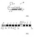
- Fig. 1is a system 10 for neurostimulation of nerves in a highly schematized view.
- the system 10includes an implantable, here eight-channel, pacemaker 11, which is shown in the drawing significantly undersized compared to a collection electrode 12 also included in the system 10.
- the pacemaker 11is connected via a connecting cable 13, which, as will be explained later, a plurality of electrically insulated from each other insulated lines, with the collecting electrode 12.
- the connection cable 13opens into a second axial end 15, which is remote from a first, distal end 14, of the wire-shaped collecting electrode 12, which is essentially contoured as an elongate cylinder body.
- the substantially cylindrical lateral surface 16 of the collecting electrode 12comprises in the preferred embodiment shown a total of eight sheath segment electrodes 1 to 8 counted starting from the first end 14.
- the sheath segment electrodes 1 to 8are individually controlled by the pacemaker 11 and are electrically isolated from each other. For this purpose is located between each two of the axially successively arranged jacket segment electrodes 1, 2; 2, 3; 3, 4; 4, 5; 5, 6; 6, 7; 7, 8 are each an insulating section 101 to 107, also counted in ascending order, starting from the first end 14 of the collecting electrode 12.
- the axial extent of the third insulating section 103, counted from the first end 14,is approximately twice as large as the axial extensions of all the other insulating sections 101, 102 and 104 to 107 in the illustrated embodiment
- Sections 101, 102 and 104 to 107have the same axial extent, of about 3mm in this embodiment.
- the circumferentially closed, ring-segment-shaped sheath segment electrodes 1 to 8are all of the same size and all have the same axial extent of 3 mm in the embodiment shown.
- the Axialersteckung the total collector electrode 12is 57mm in the embodiment shown.
- the diameteris 1 mm.
- Fig. 1further shows that in the plane of the drawing to the right of the first sheath electrode, a first insulating end portion 17 is provided which is spaced from a second end portion 18 forming the second end 18 and disposed away.
- Fig. 2shows in a comparison to Fig. 1 This also includes eight sheath segment electrodes 1 to 8 and is otherwise formed as the in Fig. 1 illustrated collecting electrode 12th
- each sheath segment electrode 1 to 8is contacted individually with an insulated electrical (control) line 201 to 208, all lines 201 to 208 being led out of the collecting electrode 12, in the embodiment shown at the second, proximal end 15 Up to this point they are guided inside the collecting electrode with radial distance to the peripheral wall (lateral surface).
- the lines 201 to 208unite into a single provided with a jacket 20 connecting cable 13 for contacting the in Fig. 2 not shown pacemaker.
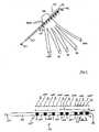
- Fig. 3shows a preferred arrangement of a trained according to the concept of the invention collecting electrode 12 in the human body.
- This collection electrode 12is located on the pudendal nerve (PN) with the first three sheath segment electrodes 1 to 3 (first group), whereas the other sheath segment electrodes 4 to 8 (second group) are across the entire sacral plexus - from the lumbosacral trunk to the S5 extend.
- PNpudendal nerve
- connection cable 13which is led out axially at the second end 15, leads to the pacemaker (generator) with which the entirety of the jacket segment electrodes 1 to 8 can be acted upon by a suitable stimulation pattern.
- the arrow 21indicates the position of the pacemaker, not shown.
- Fig. 4the most preferred embodiment of a collecting electrode 12 is shown, which via a connecting cable 13, at the axial end of the collecting electrode 12 is formed, to a, preferably eight-channel pacemaker, as this example in Fig. 1 is shown, can be connected.
- a connecting cable 13at the axial end of the collecting electrode 12 is formed, to a, preferably eight-channel pacemaker, as this example in Fig. 1 is shown, can be connected.
- electrical connection lines within the connecting cable 13 and within the collecting electrode 12 for contacting the jacket segment electrodes 1 to 8has been omitted for reasons of clarity.
- the sheath segment electrodes 1 to 8 in the embodiment according to Fig. 4analogous to Fig. 2 be contacted.
- the collecting electrode 12comprises, by means of a pacemaker, individually or in groups controllable sheath segment electrodes 1 to 8, wherein the sheath segment electrodes 1 to 8 are all the same length, i. have the same axial extension I1 to 18, of about 3mm in the embodiment shown.
- insulating section 101 to 107is arranged, which electrically insulated from each other or a short circuit prevents the respectively juxtaposed, ie immediately adjacent jacket segment electrodes.
- two types of such insulating portionsare provided, namely, the insulating portions 103, 105, 106, 107 having a larger axial extent and the insulating portions 101, 102 and 104 having a smaller axial extent.
- the axial extent of the insulating sections 101, 102, 104 with the smaller axial extent a101, a102 and a104corresponds to the axial extent I1 to I8 of the shroud segment electrodes 1 to 8, ie 3 mm in the exemplary embodiment shown.
- the axial extent of the insulating portions 101, 102, 104 with the smaller axial extent a101, a102 and a104is the same in the embodiment shown.
- the jacket segment electrodes 1 to 8 and the insulating sections 101 to 107are counted starting from the (free) first end 14 of the collector electrode 12.
- the axial extent a103, a105, a106, a107 of each of the insulating portions 103, 105, 106 and 107corresponds to the double axial extent a101, a102, a104 of one of the insulating portions 101, 102, 104.
- an insulating section 101 with a small axial extent a101Between the first and the second sheath segment electrode 1, 2 there is thus an insulating section 101 with a small axial extent a101. Also, such an insulating portion 102 having a small axial extent a102 is located between the second and third sheath segment electrodes 2, 3. Between the third and fourth sheath segment electrodes 3, 4 is an insulating portion 103 having a large axial extent a103, which corresponds to twice the axial extent of one of the insulating sections 101, 102.
- an insulating section 104with a small axial extent a104.
- the particularly advantageous collection electrode showncan be used to stimulate the sacral nerve roots 1, 2, 3, 4/5 or simultaneously to stimulate the pudendal nerve and the sciatic nerve, in particular together with the gluteus Iferio nerve.
Landscapes
- Health & Medical Sciences (AREA)
- Neurology (AREA)
- Neurosurgery (AREA)
- Orthopedic Medicine & Surgery (AREA)
- Cardiology (AREA)
- Heart & Thoracic Surgery (AREA)
- Engineering & Computer Science (AREA)
- Biomedical Technology (AREA)
- Nuclear Medicine, Radiotherapy & Molecular Imaging (AREA)
- Radiology & Medical Imaging (AREA)
- Life Sciences & Earth Sciences (AREA)
- Animal Behavior & Ethology (AREA)
- General Health & Medical Sciences (AREA)
- Public Health (AREA)
- Veterinary Medicine (AREA)
- Electrotherapy Devices (AREA)
Description
Translated fromGermanDie Erfindung betrifft eine in den menschlichen Körper laparoskopisch implantierbare, drahtförmige, Sammelelektrode zur Neurostimulation von Nerven oder als Sensor zur Detektion von Nervenimpulsen, umfassend mehrere einzeln und/oder in Gruppen kontaktierbare Mantelsegmentelektroden, die axial in Richtung der Längserstreckung der Sammelelektrode hintereinander angeordnet sind, wobei axial zwischen jeweils zwei benachbarten Sammelsegmentelektroden ein isolierender Abschnitt zum elektrischen voneinander Isolieren der jeweils zwei benachbarten Mantelsegmentelektroden angeordnet ist.The invention relates to a laparoscopically implantable in the human body, wire-shaped collection electrode for neurostimulation of nerves or as a sensor for the detection of nerve impulses, comprising a plurality of individually and / or contactable in combination shell segment electrodes, which are arranged axially in the direction of the longitudinal extension of the collecting electrode one behind the other, wherein axially between each two adjacent collection segment electrodes, an insulating portion for electrically insulating each of the two adjacent shell segment electrodes is arranged.
Es ist bekannt, zur Neurostimulation von Nerven (z.B. plexus sacralis, nervus ischiadicus, nervus pudendus, nervus femoralis) im kleinen Becken Sammelelektroden mit acht axial voneinander beabstandeten Mantelsegmentelektroden einzusetzen, die üblicherweise laparaskopisch implantiert werden. Dabei ist die Sammelelektrode über ein Anschlusskabel mit einem Schrittmacher verbunden, der die Sammelelektrode mit einem Stimulationsmuster beaufschlagt und dabei die Mantelsegmentelektroden einzeln ansteuert, um den gewünschten Nerv selektiv zu stimulieren. Bei den bekannten Sammelelektroden sind die jeweils benachbarten Mantelsegmentelektroden gleich beabstandet und zwar über jeweils einen, zwei benachbarte Mantelsegmentelektroden elektrisch voneinander isolierenden Abschnitt, wobei sämtliche isolierende Abschnitte die gleiche Axialerstreckung aufweisen. Das Problem bei der Implantation der Sammelelektrode ist die korrekte Positionierung der Sammelelektrode auf dem zu stimulierenden Nerv. Bei nicht optimaler Platzierung kommt es vor, dass der gewünschte Stimulationseffekt nicht eintritt und schlimmstenfalls das Patientenleiden sogar verschlimmert wird.It is known to insert for neurostimulation of nerves (e.g., plexus sacralis, sciatic nerve, pudendal nerve, femoral nerve) in the pelvic collecting electrodes with eight axially spaced sheath segment electrodes, which are commonly implanted laparoscopically. In this case, the collecting electrode is connected via a connecting cable with a pacemaker, which acts on the collecting electrode with a stimulation pattern and thereby individually drives the mantle segment electrodes in order to selectively stimulate the desired nerve. In the known collecting electrodes, the respectively adjacent sheath segment electrodes are equally spaced, specifically via one, two adjacent sheath segment electrodes, which are electrically mutually insulating from each other, wherein all the insulating sections have the same axial extent. The problem with the implantation of the collecting electrode is the correct positioning of the collecting electrode on the nerve to be stimulated. In the case of a non-optimal placement, the desired stimulation effect does not occur and, in the worst case, the patient's condition is even aggravated.
Aus der
Aus der
Die
Zum weiteren Stand der Technik wird zudem noch die
Aus der
Ausgehend von dem vorgenannten Stand der Technik liegt der Erfindung die Aufgabe zugrunde, eine verbesserte Sammelelektrode zur Nervenstimulation anzugeben, die dem Operateur mehr Positionierungsspielraum lässt und/oder mit der verbesserte Stimulationsergebnisse erzielbar sind. Insbesondere soll die Sammelelektrode derart ausgebildet sein, dass auch bei einer nicht optimalen (exakten) Positionierung eine gute Nervenstimulation ermöglicht wird. Besonders bevorzugt ist es, wenn mit der Sammelelektrode gleichzeitig zwei Nerven stimulierbar sind. Ferner besteht die Aufgabe darin, ein System, umfassend einen Schrittmacher und eine wie zuvor beschrieben verbesserte Sammelelektrode anzugeben.Based on the aforementioned prior art, the invention has for its object to provide an improved collection electrode for nerve stimulation, which leaves the surgeon more positioning latitude and / or can be achieved with the improved stimulation results. In particular, should Collecting electrode be designed so that even with a non-optimal (exact) positioning a good nerve stimulation is possible. It is particularly preferred if two nerves can be stimulated simultaneously with the collecting electrode. It is a further object to provide a system comprising a pacemaker and a collection electrode as described above.
Hinsichtlich der Sammelelektrode wird die Aufgabe mit den Merkmalen des Anspruchs 1 gelöst.With regard to the collecting electrode, the object is achieved with the features of
Hinsichtlich des Systems wird die Aufgabe durch die Kombination eines Schrittmachers mit einer nach dem Konzept der Erfindung ausgebildeten Sammelelektrode gelöst.With regard to the system, the object is achieved by the combination of a pacemaker with a collecting electrode designed according to the concept of the invention.
Vorteilhafte Weiterbildungen der Erfindung sind in den Unteransprüchen angegeben. In den Rahmen der Erfindung fallen sämtliche Kombinationen aus zumindest zwei von in der Beschreibung, den Ansprüchen und/oder den Figuren offenbarten Merkmalen.Advantageous developments of the invention are specified in the subclaims. All combinations of at least two features disclosed in the description, the claims and / or the figures fall within the scope of the invention.
Der Erfindung liegt der Gedanke zugrunde, dass der von einem der isolierenden Abschnitte bestimmte Axialabstand zwischen zwei der Mantelsegmentelektroden größer ist als ein (anderer) Axialabstand zwischen zwei Mantelsegmentelektroden. Anders ausgedrückt wird erfindungsgemäß von der im Stand der Technik vorgesehenen Gleichbeabstandung sämtlicher Mantelsegmentelektroden abgewichen, derart, dass die Axialerstreckung mindestens eines isolierenden Abschnitts größer ist als die Axialerstreckung eines anderen, vorzugsweise benachbarten, isolierenden Abschnitts. Ganz besonders bevorzugt ist es dabei, wenn die Axialerstreckung von mindestens zwei der übrigen (axialkürzeren) isolierenden Abschnitte, zumindest näherungsweise, gleich ist. Überraschenderweise werden mit einem nach dem Konzept der Erfindung ausgebildeten Sammelelektrode verbesserte Stimulationsergebnisse erzielt, d.h. die Wahrscheinlichkeit einer Linderung von Patientenbeschwerden wird erhöht. Mit der nach dem Konzept der Erfindung ausgebildeten Sammelelektrode ist eine selektivere Stimulierung von Nerven möglich, als mit den aus dem Stand der Technik bekannten Sammelelektroden. Auch ist eine nach dem Konzept der Erfindung ausgebildete Elektrode überraschend unempfindlicher gegenüber einer (geringen) Fehlpositionierung, d.h. eine (geringe) Fehlpositionierung hat einen geringeren Einfluss auf das Stimulationsergebnis, als dies bei Sammelelektroden nach dem Stand der Technik der Fall ist, bei denen sämtliche Mantelsegmentelektroden gleich beabstandet sind. Ein weiterer wesentlicher Vorteil der erfindungsgemäßen Sammelelektrode ist, dass diese - bei geeigneter Positionierung - selektiv zwei benachbarte Nerven gleichzeitig stimulieren kann, insbesondere indem zwei über den axial längeren isolierenden Abschnitt voneinander getrennte Gruppen von Mantelsegmentelektroden auf die zwei Nerven verteilt angeordnet werden. So ist mit einer derartig ausgebildeten Sammelelektrode beispielsweise eine selektive Pudendus-Stimulation und eine selektive Ischias-Stimulation mit einer einzigen Sammelelektrode möglich.The invention is based on the idea that the axial distance, determined by one of the insulating sections, between two of the jacket segment electrodes is greater than a (different) axial spacing between two jacket segment electrodes. In other words, according to the invention deviates from the uniform spacing of all the shell segment electrodes provided in the prior art, such that the axial extent of at least one insulating portion is greater than the axial extent of another, preferably adjacent, insulating portion. It is very particularly preferred if the axial extent of at least two of the other (axialkürzeren) insulating sections, at least approximately, is the same. Surprisingly, improved stimulation results are achieved with a collecting electrode designed according to the concept of the invention, ie the likelihood of alleviating patient complaints is increased. With the collecting electrode formed according to the concept of the invention, a more selective stimulation of nerves is possible, as with the collecting electrodes known from the prior art. Also, an electrode formed according to the concept of the invention is surprisingly less sensitive to (small) mispositioning, ie a (small) mispositioning has a smaller influence on the stimulation result than is the case with collecting electrodes according to the prior art in which all the sheath segment electrodes are equally spaced. A further significant advantage of the collecting electrode according to the invention is that it can - with suitable positioning - selectively stimulate two adjacent nerves simultaneously, in particular by arranging two groups of sheath segment electrodes, which are separated from one another via the axially longer insulating section, distributed over the two nerves. Thus, with such a collection electrode, for example, a selective pudendal stimulation and a selective sciatic stimulation with a single collecting electrode possible.
Die nach dem Konzept der Erfindung ausgebildete Sammelelektrode dient, wie vorerwähnt, in erster Linie zur Neurostimulation, indem die Sammelelektrode bzw. die Mantelsegmentelektroden der Sammelelektrode mit einem bestimmten Stimulationsmuster mittels eines Schrittmachers beaufschlagt wird. Bevorzugt wird das Stimulationsmuster in Abhängigkeit der zu behandelnden Indikation gewählt. Die nach dem Konzept der Erfindung ausgebildete Sammelelektrode kann alternativ auch als Sensor zum Abgreifen von Nervenimpulsen eingesetzt werden. Die nach dem Konzept der Erfindung ausgebildete Sammelelektrode eignet sich bevorzugt zum Einsatz bei folgenden Indikationen:
- Neurogene oder nicht neurogene Harnblasenüberaktivität (Sakral- und Pudendal-Nervstimulation)
- Neurogene oder nicht neurogene, myogene Harnblasen-Hypo-/Atonie
- Pudendus Blockade (bei Querschnittslähmung)
- Blasen-/Darmentleerung bei Hyperaktivität Deblockade (bei Querschnittslähmung)
- Spastizität in den unteren Extremitäten, insbesondere bei Multipler Sklerose, Polyneuropatie, Tetra/Paraplegie, etc. (Ischiasnervstimulation)
- Errektions- und Sexualprobleme, Errektionsverlust, Ejakulationsunvermögen, vorzeitige Ejakulation (Ischiasnervenwurzelstimulation/Pudendalnervstimulation)
- Orgasmusunfähig bei Frauen
- Neurogene und nicht nicht neurogene Harnblasen/Rektum-Inkontinenz (Pudendalnervstimulation)
- Chronische Verstopfungen
- Verschiedene Pathologien und Beschwerden (gleichzeitige Stimulation verschiedener - mindestens zwei - Nerven)
- Pudendal Neuralgie => Neuralgie Ischias Nerv
- Neurogenic or non-neurogenic bladder overactivity (sacral and pudendal nerve stimulation)
- Neurogenic or non-neurogenic, myogenic bladder hypo / atony
- Pudendal blockade (in paraplegia)
- Bladder / defecation in hyperactivity deblocking (in paraplegia)
- Spasticity in the lower extremities, especially in multiple sclerosis, polyneuropathy, tetra / paraplegia, etc. (sciatic nerve stimulation)
- Achievement and sexual problems, loss of recovery, ejaculation inability, premature ejaculation (sciatic nerve root stimulation / Pudendalnervstimulation)
- Orgasm incompetent in women
- Neurogenic and non-neurogenic urinary bladder / rectal incontinence (pudendal nerve stimulation)
- Chronic blockages
- Various pathologies and complaints (simultaneous stimulation of different - at least two - nerves)
- Pudendal neuralgia => Neuralgia sciatica nerve
Besonders bevorzugt ist es, wenn die Sammelelektrode drahtförmig ausgebildet ist. Unter drahtförmig ist dabei eine langgestreckte, beispielsweise stabförmige, starre oder alternativ, gegebenenfalls verformbare Ausformung zu verstehen. Bevorzugt ist die Axialerstreckung der, insbesondere drahtförmigen, Sammelelektrode aus einem Wertebereich zwischen etwa 45mm und etwa 65mm gewählt. Besonders bevorzugt beträgt die Axialerstreckung etwa 57mm. Dabei bezieht sich das Längenmaß auf den Abstand der voneinander abgewandten axialen Enden der am weitesten voneinander entfernten Mantelsegmentelektroden. Besonders zweckmäßig ist es, wenn der Durchmesser der, bevorzugt zumindest näherungsweise zylindrisch, insbesondere kreiszylindrisch, konturierten Sammelelektrode aus einem Wertebereich zwischen 0,5mm und 2mm, ganz besonders bevorzugt aus einem Wertebereich zwischen 0,8mm und 1,2mm gewählt ist. Noch weiter bevorzugt beträgt der Durchmesser etwa 1 mm.It is particularly preferred if the collecting electrode is of wire-shaped design. Under wire is an elongated, for example, rod-shaped, rigid or alternatively, optionally deformable formation to understand. Preferably, the axial extent of the, in particular wire-shaped, collecting electrode is selected from a value range between about 45mm and about 65mm. Particularly preferably, the axial extent is about 57mm. In this case, the length dimension refers to the distance between the mutually remote axial ends of the furthest apart jacket segment electrodes. It is particularly useful if the diameter of, preferably at least approximately cylindrical, in particular circular cylindrical, contoured collection electrode is selected from a range of values between 0.5mm and 2mm, most preferably from a range between 0.8mm and 1.2mm. Even more preferably, the diameter is about 1 mm.
Ganz besonders bevorzugt ist es, wenn nicht nur die Axialerstreckung eines einzigen zwischen zwei der Mantelsegmentelektroden angeordneten isolierenden Abschnittes größer ist als die Axialerstreckung mindestens eines anderen zwischen zwei der Mantelsegmentelektroden angeordneten isolierenden Abschnittes, sondern wenn die Axialerstreckung von mindestens zwei, oder von ausschließlich zwei, isolierenden Abschnitten, oder von mindestens drei, oder von ausschließlich drei, isolierenden Abschnitten, oder von mindestens vier, oder von ausschließlich vier, isolierenden Abschnitten, die jeweils zwischen zwei Mantelsegmentelektroden angeordnet sind, größer ist als die Axialerstreckung mindestens eines anderen isolierenden, zwischen zwei Mantelsegmentelektroden angeordneten isolierenden Abschnittes. Ganz besonders bevorzugt ist es, wenn die Axialerstreckung der isolierenden Abschnitte, die eine größere Axialerstreckung aufweisen als mindestens ein anderer isolierender Abschnitt, zumindest näherungsweise, gleich groß ist. Bevorzugt ist die Axialerstreckung mindestens eines der isolierenden Abschnitte mit einer größeren Axialerstreckung, vorzugsweise sämtlicher isolierender Abschnitte mit einer größeren Axialerstreckung, aus einem Wertebereich zwischen etwa 4mm und etwa 8mm, ganz besonders bevorzugt zwischen etwa 5mm und etwa 7mm gewählt. Ganz besonders bevorzugt beträgt die Axialerstreckung etwa 6mm.It is very particularly preferred if not only the axial extent of a single insulating section arranged between two of the jacket segment electrodes is greater than the axial extent of at least one other between two of the sheath segment electrodes arranged insulating section, but if the axial extent of at least two, or only two, insulating sections, or of at least three, or of only three, insulating sections, or of at least four, or of only four, insulating sections, each arranged between two sheath segment electrodes is greater than the axial extent of at least one other insulating, arranged between two sheath segment electrodes insulating section. It is very particularly preferred if the axial extent of the insulating sections, which have a greater axial extent than at least one other insulating section, is at least approximately equal. Preferably, the axial extent of at least one of the insulating portions having a larger axial extent, preferably all of the insulating portions having a larger axial extent, is selected from a range between about 4mm and about 8mm, most preferably between about 5mm and about 7mm. Most preferably, the axial extent is about 6mm.
Besonders zweckmäßig ist es, wenn die Axialerstreckung mindestens eines isolierenden Abschnittes mit einer geringeren Axialerstreckung aus einem Wertebereich zwischen etwa 2mm und etwa 4mm gewählt ist. Ganz besonders bevorzugt beträgt die Axialerstreckung etwa 3mm. Besonders zweckmäßig ist es, wenn mindestens zwei isolierende Abschnitte mit einer geringeren Axialerstreckung die gleiche Axialerstreckung, vorzugsweise aus dem vorgenannten Wertebereich, aufweisen. Bevorzugt sind insgesamt drei isolierende Abschnitte mit einer geringen Axialerstreckung, insbesondere mit der identischen Axialerstreckung, vorzugsweise aus dem vorgenannten Wertebereich, vorgesehen.It is particularly expedient if the axial extent of at least one insulating section with a smaller axial extent is selected from a value range between approximately 2 mm and approximately 4 mm. Most preferably, the axial extent is about 3mm. It is particularly expedient if at least two insulating sections with a smaller axial extent have the same axial extent, preferably from the aforementioned value range. Preferably, a total of three insulating sections are provided with a small axial extent, in particular with the identical axial extent, preferably from the aforementioned value range.
In Weiterbildung der Erfindung ist mit Vorteil vorgesehen, dass die Axialerstreckung der isolierenden Abschnitte mit einer größeren Axialerstreckung, zumindest näherungsweise, gleich groß ist und/oder die Axialerstreckung der isolierenden Abschnitte mit einer geringeren Axialerstreckung, zumindest näherungsweise, gleich groß ist.In a further development of the invention is advantageously provided that the axial extent of the insulating portions with a larger axial extent, at least approximately, is the same size and / or the axial extent of the insulating portions with a smaller axial extent, at least approximately, is the same size.
In Weiterbildung der Erfindung ist mit Vorteil vorgesehen, dass die Sammelelektrode mindestens fünf axial über jeweils einen isolierenden Abschnitt voneinander beabstandete Mantelsegmentelektroden aufweist und dass, von einem ersten (insbesondere freien) Ende der Sammelelektrode her gezählt, die Axialerstreckung des die zweite und die dritte Mantelsegmentelektrode voneinander isolierenden Abschnitts oder die Axialerstreckung des isolierenden Abschnitts zwischen der dritten und der vierten Mantelsegmentelektrode oder die Axialerstreckung zwischen der vierten und der fünften Mantelsegmentelektrode größer ist als die Axialerstreckung mindestens eines anderen isolierenden Abschnitts (zwischen zwei Mantelsegmentelektroden). Gemäß einer realisierbaren Ausführungsvariante handelt es sich bei dem isolierenden Abschnitt mit der größeren Axialerstreckung um den isolierenden Abschnitt zwischen zwei Mantelsegmentelektroden mit der größten Axialerstreckung, d.h. es existiert nicht ein isolierender Abschnitt zwischen zwei Mantelsegmentelektroden, der eine größere und/oder gleich große Axialerstreckung aufweist. Wie jedoch bereits erläutert ist es möglich und bevorzugt mindestens zwei gleich lange isolierende Abschnitte vorzusehen, die eine größere Axialerstreckung aufweisen als mindestens ein isolierender, zwischen zwei Mantelsegmentelektroden angeordneter Abschnitt. Besonders zweckmäßig ist es, den Abstand zwischen der zweiten und der dritten Mantelsegmentelektrode oder zwischen der dritten oder vierten Mantelsegmentelektrode oder zwischen der vierten und der fünften Mantelsegmentelektrode größer zu wählen als den Axialabstand zwischen zwei geringer beabstandeten Mantelsegmentelektroden. Besonders gute Ergebnisse wurden mit einer Sammelelektrode erzielt, die insgesamt acht Mantelsegmentelektroden aufweist und bei der der Abstand zwischen der dritten und der vierten Mantelsegmentelektrode größer ist als der Abstand zwischen mindestens zwei anderen Mantelsegmentelektroden.In a development of the invention, it is advantageously provided that the collecting electrode has at least five jacket segment electrodes spaced apart axially over an insulating section and that, counted from a first (in particular free) end of the collecting electrode, the axial extent of the second and third jacket segment electrodes are different from one another insulating portion or the axial extent of the insulating portion between the third and the fourth sheath segment electrode or the axial extent between the fourth and the fifth sheath segment electrode is greater than the axial extent of at least one other insulating portion (between two sheath segment electrodes). According to a feasible embodiment variant, the insulating section with the larger axial extent is the insulating section between two jacket segment electrodes having the greatest axial extent, i. there is no insulating section between two sheath segment electrodes having a larger and / or equal axial extent. However, as already explained, it is possible and preferred to provide at least two insulating sections of equal length which have a greater axial extent than at least one insulating section arranged between two jacket segment electrodes. It is particularly expedient to select the distance between the second and the third shroud segment electrode or between the third or fourth shroud segment electrode or between the fourth and the fifth shroud segment electrode to be greater than the axial distance between two sheath segment electrodes spaced apart less. Particularly good results have been achieved with a collecting electrode, which has a total of eight sheath segment electrodes and in which the distance between the third and the fourth sheath segment electrode is greater than the distance between at least two other sheath segment electrodes.
Besonders bevorzugt ist eine Ausführungsvariante der Sammelelektrode, bei der diese mindestens acht, vorzugsweise ausschließlich acht kontaktierte, Mantelsegmentelektroden aufweist, wobei jeweils zwei benachbarte Mantelsegmentelektroden über einen isolierenden Abschnitt voneinander getrennt sind. Dabei ist es besonders bevorzugt, wenn, gezählt ausgehend von einem ersten Ende der Mantelsegmentelektroden, der isolierende Abschnitt zwischen der dritten und der vierten Mantelsegmentelektrode und/oder die Axialerstreckung des isolierenden Abschnittes zwischen der fünften und der sechsten Mantelsegmentelektrode und/oder die Axialerstreckung des isolierenden Abschnittes zwischen der sechsten und der siebten Mantelsegmentelektrode und/oder die Axialerstreckung des isolierenden Abschnittes zwischen der siebten und der achten Mantelsegmentelektrode größer ist als die Axialerstreckung mindestens eines der isolierenden Abschnitte der Sammelelektrode. Ganz besonders bevorzugt ist die Axialerstreckung mindestens eines der vorgenannten isolierenden Abschnitte mit einer größeren Axialerstreckung, ganz besonders bevorzugt sämtlicher vorgenannter isolierender Abschnitte mit einer größeren Axialerstreckung größer als die Axialerstreckung des isolierenden Abschnittes zwischen der ersten und der zweiten Mantelsegmentelektrode und/oder größer als die Axialerstreckung des isolierenden Abschnittes zwischen der zweiten und der dritten Mantelsegmentelektrode und/oder als die Axialerstreckung des isolierenden Abschnittes zwischen der vierten und der fünften Mantelsegmentelektrode. Ganz besonders bevorzugt ist die Axialerstreckung der vorgenannten isolierenden Abschnitte mit einer geringeren Axialerstreckung gleich groß. Ganz besonders bevorzugt beträgt die Axialerstreckung der isolierenden Abschnitte mit der geringeren Axialerstreckung zumindest näherungsweise der Axialerstreckung mindestens einer Mantelsegmentelektrode, ganz besonders bevorzugt sämtlicher Mantelsegmentelektroden.Particularly preferred is an embodiment of the collecting electrode, in which this has at least eight, preferably only eight contacted, shell segment electrodes, wherein each two adjacent shell segment electrodes are separated from each other via an insulating section. It is particularly preferred if, counted starting from a first End of the cladding segment electrodes, the insulating section between the third and fourth cladding segment electrodes and / or the axial extension of the insulating section between the fifth and sixth cladding segment electrodes and / or the axial extension of the insulating section between the sixth and seventh cladding segment electrodes and / or the axial extension of the insulating portion between the seventh and the eighth Mantelsegmentelektrode is greater than the axial extent of at least one of the insulating portions of the collecting electrode. Most preferably, the axial extent of at least one of the aforementioned insulating portions having a larger axial extent, most preferably all of the aforementioned insulating portions having a greater axial extent greater than the axial extent of the insulating portion between the first and second shell segment electrode and / or greater than the axial extent of insulating portion between the second and the third sheath segment electrode and / or as the axial extension of the insulating portion between the fourth and the fifth sheath segment electrode. Most preferably, the axial extension of the aforementioned insulating sections with a smaller axial extent is equal. Most preferably, the axial extent of the insulating portions with the smaller axial extent at least approximately the axial extent of at least one shell segment electrode, most preferably all of the shell segment electrodes.
Ganz besonders bevorzugt ist es, wenn die Axialerstreckung mindestens eines eine größere Axialerstreckung aufweisenden isolierenden Abschnittes, vorzugsweise sämtlicher Axialabschnitte mit einer größeren Axialerstreckung, um einen Faktor aus einem Wertebereich zwischen etwa 1,5 und etwa 3, vorzugsweise von etwa 2, mal größer ist als die Axialerstreckung mindestens eines anderen isolierenden Abschnittes, vorzugsweise als die Axialerstreckung sämtlicher, insbesondere gleich langer anderer isolierender Abschnitte mit einer geringeren Axialerstreckung.It is very particularly preferred if the axial extent of at least one insulating section having a larger axial extent, preferably of all axial sections with a larger axial extent, is larger by a factor of between about 1.5 and about 3, preferably about 2 times the axial extension of at least one other insulating portion, preferably as the axial extension of all, in particular the same length of other insulating portions having a smaller axial extent.
Bevorzugt ist die Axialerstreckung der Mantelsegmentelektroden aus einem Wertebereich zwischen etwa 2mm und etwa 4mm gewählt. Mit Vorteil beträgt sie etwa 3mm. Bevorzugt ist die Axialerstreckung des mindestens einen axial längeren isolierenden Abschnitts aus einem Wertebereich zwischen 5mm und 7mm gewählt, bevorzugt beträgt sie etwa 6mm. Mit Vorteil ist die Axialerstreckung der anderen (kürzeren) isolierenden Abschnitte aus einem Wertebereich zwischen etwa 2mm und etwa 4mm gewählt, bevorzugt beträgt sie etwa 3mm.Preferably, the axial extent of the sheath segment electrodes is selected from a value range between about 2mm and about 4mm. Advantageously, it is about 3mm. The axial extension of the at least one axially longer insulating section is preferably selected from a value range between 5 mm and 7 mm, preferably about 6 mm. Advantageously, the axial extent of the other (shorter) insulating sections is selected from a value range between about 2 mm and about 4 mm, preferably about 3 mm.
Wie bereits erwähnt, ist eine Ausführungsform mit insgesamt acht Mantelsegmentelektroden besonders bevorzugt. Es sind auch Ausführungsvarianten mit 6, 7, 9, 10 oder gegebenenfalls sogar mehr als 10 Sammelelektroden realisierbar.As already mentioned, an embodiment with a total of eight sheath segment electrodes is particularly preferred. There are also embodiments with 6, 7, 9, 10 or possibly even more than 10 collecting electrodes feasible.
Wie eingangs erwähnt, ist es besonders bevorzugt, wenn jede Mantelsegmentelektrode einzeln und/oder in Gruppen elektrisch kontaktierbar/kontaktiert, insbesondere ansteuerbar, ist. Um dies zu ermöglichen, ist in Weiterbildung der Erfindung mit Vorteil vorgesehen, dass zu jeder Mantelsegmentelektrode oder zu jeder Gruppe von Mantelsegmentelektroden, vorzugsweise im Innern der Sammelelektrode, eine die jeweilige Mantelsegmentelektrode kontaktierende elektrische Leitung geführt ist, wobei die die Mantelsegmentelektroden kontaktierenden elektrischen Leitungen voneinander elektrisch isoliert sind, um einen Kurzschluss zu vermeiden. Bevorzugt sind die Leitungen in einem gemeinsamen Anschlusskabel zusammengefasst, welches die Sammelelektrode mit einem Schrittmacher verbindet. Bevorzugt ist der Durchmesser des Anschlusskabels aus einem Wertebereich zwischen etwa 0,5mm und 2mm, vorzugsweise zwischen 0,8mm und 1,2mm, gewählt. Bevorzugt beträgt der Durchmesser etwa 1 mm. Bevorzugt entspricht der Durchmesser des Anschlusskabels, zumindest näherungsweise, dem Durchmesser der Sammelelektrode.As mentioned in the introduction, it is particularly preferred if each sheath segment electrode can be contacted / contacted electrically, in particular controllable, individually and / or in groups. In order to make this possible, it is advantageously provided in the invention that for each shell segment electrode or each group of shell segment electrodes, preferably in the interior of the collecting electrode, an electrical line contacting the respective shell segment electrode is guided, wherein the electric lines contacting the shell segment electrodes are electrically connected to each other are isolated to prevent a short circuit. Preferably, the lines are combined in a common connection cable, which connects the collecting electrode with a pacemaker. Preferably, the diameter of the connection cable is selected from a value range between about 0.5 mm and 2 mm, preferably between 0.8 mm and 1.2 mm. Preferably, the diameter is about 1 mm. The diameter of the connecting cable preferably corresponds, at least approximately, to the diameter of the collecting electrode.
Bevorzugt ist das Anschlusskabel weiter entfernt von dem weiter zuvor diskutierten ersten, insbesondere distalen, Ende der Sammelelektrode als zu einem von dem ersten axialen Ende abgewandten zweiten axialen Ende. Anders ausgedrückt mündet das Anschlusskabel in die Sammelelektrode an einer Stelle, die weiter von dem ersten als von dem zweiten Ende beabstandet ist; mit Vorteil befindet sich diese Mündungsstelle am zweiten Ende. Beispielweise tritt das Anschlusskabel axial in die Sammelelektrode ein.Preferably, the connection cable is further away from the first, in particular distal, end of the collecting electrode discussed above than to a second axial end facing away from the first axial end. In other words, the connection cable opens into the collecting electrode at one point, further spaced from the first end than the second end; Advantageously, this estuary is located at the second end. For example, the connecting cable enters the collecting electrode axially.
Ganz besonders bevorzugt ist Ausführungsvariante, bei der die Sammelelektrode endseitig an dem Anschlusskabel angeordnet ist. Dies bedeutet, dass die eigentliche Sammelelektrode, d.h. die Anordnung der Mantelsegmentelektroden das Anschlusskabel axial endseitig abschließt bzw. einen Endabschnitt des Anschlusskabels bildet. Somit befindet sich die Sammelelektrode nicht an einer beliebigen Axialposition am Anschlusskabel, sondern ausdrücklich axial endseitig, um so die Sammelelektrode optimal, insbesondere durch Angreifen am Anschlusskabel, positionieren zu können. Die Sammelelektrode bildet also die endseitige Fortsetzung des Anschlusskabels bzw. des Anschlusskabelendes, woraus eine drahtförmige Ausbildung der Sammelelektroden-Anschlusskabelanordnung resultiert. Bevorzugt entspricht der Durchmesser des Anschlusskabels, zumindest näherungsweise (± 20%, vorzugsweise ± 10%), dem Durchmesser der, vorzugsweise von dem Endabschnitt des Anschlusskabels gebildeten, Sammelelektrode.Very particular preference is given embodiment variant in which the collecting electrode is arranged on the end of the connecting cable. This means that the actual collector electrode, i. the arrangement of the sheath segment electrodes terminates the connection cable axially end or forms an end section of the connection cable. Thus, the collecting electrode is not at any axial position on the connection cable, but expressly axial end, so as to optimally position the collecting electrode, in particular by attacking the connection cable. The collecting electrode thus forms the end-side continuation of the connection cable or the connection cable end, resulting in a wire-shaped design of the collecting electrode connection cable arrangement. The diameter of the connection cable preferably corresponds at least approximately (± 20%, preferably ± 10%) to the diameter of the collector electrode, which is preferably formed by the end section of the connection cable.
Im Hinblick auf die metrische Ausgestaltung der isolierenden Abschnitte und/oder der Mantelsegmentelektroden gibt es unterschiedliche Möglichkeiten. Diese können sich beispielsweise nur über Umfangsabschnitte erstrecken. Besonders bevorzugt ist es jedoch, wenn es sich bei den isolierenden Abschnitten und/oder den Mantelsegmentelektroden um umfangsgeschlossene Ringsegmente handelt.With regard to the metric configuration of the insulating sections and / or the sheath segment electrodes, there are different possibilities. These can for example only extend over peripheral sections. However, it is particularly preferred if the insulating sections and / or the sheath segment electrodes are circumferentially closed ring segments.
Die Erfindung führt auch auf ein System, umfassend eine nach dem Konzept der Erfindung ausgebildete Sammelelektrode, die elektrisch leitend über eine Anschlusskabel, vorzugsweise ebenfalls implantierbaren, Schrittmacher verbunden ist, der bevorzugt derart ausgebildet ist, dass die Sammelelektrode bzw. die einzelnen Mantelsegmentelektroden mit einem Stimulationsmuster beaufschlagbar sind. Bevorzugt kann aus vorgegebenen Stimulationsmustern, insbesondere durch den Operateur oder einem Medizintechniker ausgewählt werden. Der Schrittmacher umfasst bevorzugt eine Energiequelle und eine Steuereinheit, mit der Mantelsegmentelektroden auf ein unterschiedliches elektrisches Potential legbar sind.The invention also leads to a system comprising a collection electrode designed according to the concept of the invention, which is electrically conductively connected via a connection cable, preferably also implantable, pacemaker, which is preferably designed such that the collection electrode or the individual jacket segment electrodes with a stimulation pattern can be acted upon. Preferably, it can be selected from predetermined stimulation patterns, in particular by the surgeon or a medical technician become. The pacemaker preferably comprises an energy source and a control unit, with which the shell segment electrodes can be laid to a different electrical potential.
Besonders bevorzugt handelt es sich um einen acht-kanaligen Schrittmacher.Most preferably, it is an eight-channel pacemaker.
Als besonders zweckmäßig hat es sich herausgestellt, wenn die distalen drei Mantelsegmentelektroden, also die drei ersten Mantelsegmentelektroden gezählt vom ersten Ende der Sammelelektrode mit Masse, Pluspotential bzw. ansteuerbar sind, insbesondere zu dem Zweck den Nervus pudendus tripolar stimulieren zu können und somit die Selektionsmöglichkeit dieser Simulation im Vergleich zum Stand der Technik noch zu erweitern. Eine derartige Ausführungsform würde zudem die Stimulation des gesamten sakralen Plexus, vom Truncus lumbosacralis bis S5 mit einer einzigen Elektrode ermöglichen.It has proved particularly expedient if the distal three jacket segment electrodes, that is to say the three first jacket segment electrodes counted from the first end of the collector electrode, can be stimulated with positive potential, in particular for the purpose of stimulating the pudendal tripolar nerve, and thus the possibility of selecting them Simulation in comparison to the prior art still to expand. Such an embodiment would also allow for the stimulation of the entire sacral plexus, from the lumbosacral truncus to S5, with a single electrode.
Weitere Vorteile, Merkmale und Einzelheiten der Erfindung ergeben sich aus der nachfolgenden Beschreibung bevorzugter Ausführungsbeispiele sowie anhand der Zeichnungen.Further advantages, features and details of the invention will become apparent from the following description of preferred embodiments and from the drawings.
Diese zeigen in:
- Fig. 1:
- ein System, umfassend einen über ein Anschlusskabel mit einer Sammelelektrode verbundenen Schrittmacher,
- Fig. 2:
- eine detaillierte Darstellung der Ausführungsvariante der Sammelelektrode gemäß
Fig. 1 , - Fig. 3:
- eine Darstellung einer implantierten bei gleichzeitig auf zwei Nerven angeordneten Sammelelektrode, und
- Fig. 4
- eine bevorzugte Ausführungsvariante einer Sammelelektrode mit acht Mantelsegmentelektroden.
- Fig. 1:
- a system comprising a pacemaker connected to a collecting electrode via a connecting cable,
- Fig. 2:
- a detailed representation of the embodiment of the collecting electrode according to
Fig. 1 . - 3:
- a representation of an implanted simultaneously arranged on two nerves collecting electrode, and
- Fig. 4
- a preferred embodiment of a collecting electrode with eight sheath segment electrodes.
In den Figuren sind gleiche Elemente und Elemente mit der gleichen Funktion mit den gleichen Bezugszeichen gekennzeichnet.In the figures, like elements and elements having the same function are denoted by the same reference numerals.
In
Die im Wesentlichen zylindrische Mantelfläche 16 der Sammelelektrode 12 umfasst in dem gezeigten, bevorzugten Ausführungsbeispiel insgesamt acht Mantelsegmentelektroden 1 bis 8 aufsteigend gezählt ausgehend von dem ersten Ende 14. Die Mantelsegmentelektroden 1 bis 8 sind einzeln mittels des Schrittmachers 11 ansteuerbar und sind elektrisch voneinander isoliert. Hierzu befindet sich zwischen jeweils zwei der axial hintereinander angeordneten Mantelsegmentelektroden 1, 2; 2, 3; 3, 4; 4, 5; 5, 6; 6, 7; 7, 8 jeweils ein isolierender Abschnitt 101 bis 107, ebenfalls aufsteigend gezählt, ausgehend vom ersten Ende 14 der Sammelelektrode 12. Aus
Aus
Durch den größeren Abstand zwischen der dritten und vierten Mantelsegmentelektrode 16 werden die erfindungsgemäßen Vorteile erreicht.Due to the greater distance between the third and fourth sheath segment electrode 16, the advantages according to the invention are achieved.
Aus der schematischen Darstellung gemäß
Das am zweiten Ende 15 axial herausgeführte Anschlusskabel 13 führt zu dem Schrittmacher (Generator) mit dem die Gesamtheit der Mantelsegmentelektroden 1 bis 8 mit einem geeigneten Stimulationsmuster beaufschlagbar ist. Der Pfeil 21 deutet die Lage des nicht gezeigten Schrittmachers an.The
Die in
- SN:
- Ischiasnerv
- PN:
- Nervus Pudendus
- SGN:
- Superior Gluteal Nerv
- LST:
- Lumbo Sakral Truncus
- S1:
Sakralnervenwurzel 1- S2:
Sakralnervenwurzel 2- S3:
Sakralnervenwurzel 3- S4/5:
Sakralnervenwurzel 4/5
- SN:
- sciatic nerve
- PN:
- Nervus pudendus
- SGN:
- Superior gluteal nerve
- LST:
- Lumbo sacral truncus
- S1:
Sacral nerve root 1- S2:
Sacral nerve root 2- S3:
Sacral nerve root 3- S4 / 5:
Sacral nerve root 4/5
In
In dem gezeigten Ausführungsbeispiel beträgt die Länge, d.h. die Axialerstreckung I der Sammelelektrode 12, gemessen zwischen den voneinander abgewandten Enden der am weitesten voneinander entfernten Mantelsegmentelektroden 1 und 8, 57mm.In the embodiment shown, the length, ie the axial extension I of the collecting
Die Sammelelektrode 12 umfasst, mittels eines Schrittmachers einzeln oder in Gruppen ansteuerbare Mantelsegmentelektroden 1 bis 8, wobei die Mantelsegmentelektroden 1 bis 8 alle gleich lang sind, d.h. die gleiche Axialerstreckung I1 bis 18, von in dem gezeigten Ausführungsbeispiel etwa 3mm aufweisen.The collecting
Aus
Die Axialerstreckung a103, a105, a106, a107 jedes der isolierenden Abschnitte 103, 105, 106 und 107 entspricht der doppelten Axialerstreckung a101, a102, a104 von einem der isolierenden Abschnitte 101, 102, 104.The axial extent a103, a105, a106, a107 of each of the insulating
Zwischen der ersten und der zweiten Mantelsegmentelektrode 1, 2 befindet sich also ein isolierender Abschnitt 101 mit einer geringen Axialerstreckung a101. Ebenso befindet sich ein solcher isolierender Abschnitt 102 mit einer geringen Axialerstreckung a102 zwischen der zweiten und der dritten Mantelsegmentelektrode 2, 3. Zwischen der dritten und der vierten Mantelsegmentelektrode 3, 4 befindet sich ein isolierender Abschnitt 103 mit einer großen Axialerstreckung a103, die der doppelten Axialerstreckung von einem der isolierenden Abschnitte 101, 102 entspricht.Between the first and the second
Zwischen der vierten und der fünften Mantelsegmentelektrode befindet sich ein isolierender Abschnitt 104 mit einer geringen Axialerstreckung a104. Zwischen der fünften und der sechsten, zwischen der sechsten und der siebten sowie zwischen der siebten und der achten Mantelsegmentelektrode 5, 6; 6, 7; 7, 8 befindet sich jeweils ein isolierender Abschnitt 105, 106, 107 mit einer großen Axialerstreckung a105, a106 bzw. a107, wobei die Axialerstreckungen a103, a105, a106 und a107 in dem gezeigten Ausführungsbeispiel identisch sind und etwa der doppelten Axialerstreckung der isolierenden Abschnitte 101, 102, 104 mit einer geringen Axialerstreckung entsprechen.Between the fourth and fifth sheath segment electrodes is an insulating
Es auch eine (nicht gezeigte) Ausführungsvariante denkbar, bei der sich die Axialerstreckung von mindestens zwei isolierenden Abschnitten 103, 105, 106, 107 mit einer größeren Axialerstreckung unterscheidet. Ebenso ist es denkbar, dass sich die Axialerstreckung von mindestens zwei isolierenden Abschnitten 101, 102 und 104 mit einer geringeren Axialerstreckung unterscheidet.It is also an embodiment (not shown) conceivable in which the axial extent of at least two insulating
Die in
- 1 - 81 - 8
- MantelsegmentelektrodenCoat segment electrodes
- 1010
- Systemsystem
- 1111
- Schrittmacherpacemaker
- 1212
- Sammelelektrodecollecting electrode
- 1313
- Anschlusskabelconnection cable
- 1414
- erstes Endefirst end
- 1515
- zweites Endesecond end
- 1616
- Mantelflächelateral surface
- 1717
- erster Endabschnittfirst end section
- 1818
- zweiter Endabschnittsecond end section
- 2020
- Mantelcoat
- 2121
- Pfeilarrow
- 101 - 107101-107
- Isolierende AbschnitteInsulating sections
- 201 - 208201-208
- elektrische Leitungenelectric lines
- II
- Axialerstreckung der SammelelektrodeAxial extension of the collecting electrode
- a101 - a107a101 - a107
- Axialerstreckungen von isolierenden AbschnittenAxial extensions of insulating sections
- I1 - I8I1 - I8
- Axialerstreckungen von MantelsegmentelektrodenAxial extensions of sheath segment electrodes
Claims (12)
- Wire-shaped collector electrode (12) which can be implanted laparoscopically into the human body for the neurostimulation of the sacral nerve roots 1, 2, 3, 4/5 or for the simultaneous stimulation of the pudendal nerve and the sciatic nerve, comprising a plurality of sheathed electrode segments (1-8) which can be contacted individually and/or in groups and are arranged axially in succession in the direction of the longitudinal extension of the collector electrode (12), wherein an insulating portion (101-107) is arranged axially between each two adjacent sheathed electrode segments (1-8) to electrically insulate each of the two adjacent sheathed electrode segments (1-8) from each other, wherein the axial extension of two of the insulating portions (101-107) is different, wherein at least five sheathed electrode segments (1, 2, 3, 4, 5) are provided, and wherein, when viewed from a first end (14) of the collector electrode (12), the axial extension of the insulating portion (103) between the third and the fourth sheathed electrode segment (3, 4) is greater than the axial extension of at least one other insulating portion (101, 102, 104, 107), wherein the axial extension of the one insulating portion (103) between the third and the fourth sheathed electrode segment (3, 4) is greater than the axial extension of at least one other insulating portion (101, 102, 104-107) by a factor in a range between 1.5 and 3 times.
- Collector electrode according to claim 1,characterised in that at least or exclusively two, or at least or exclusively three, or at least or exclusively four insulating portions (103, 105, 106, 107) are provided between each two sheathed electrode segments (3, 4; 5, 6; 6, 7; 7, 8), which insulating portions have a greater axial extension than at least one other insulating portion (101, 102, 104) between two sheathed electrode segments (1, 2; 2, 3; 4, 5), or than at least or exclusively two other insulating portions (101, 102, 104) between each two sheathed electrode segments (1, 2; 2, 3; 4, 5), or than at least or exclusively three insulating portions (101, 102, 104) between each two sheathed electrode segments (1, 2; 2, 3; 4, 5).
- Collector electrode according to claim 2,characterised in that at least two of the insulating portions (103, 105, 106, 107) having the greater axial extension, preferably all insulating portions (103, 105, 106, 107) having the greater axial extension, have the same axial extension, and/orin that at least two of the insulating portions (101, 102, 104) having the smaller axial extension, preferably all insulating portions (101, 102, 104) having the smaller axial extension, have the same axial extension.
- Collector electrode according to any of the preceding claims,characterised in that at least or exclusively eight sheathed electrode segments (1-8) are provided, andin that, when viewed from the first end (14) of the collector electrode (12), the insulating portion (103) between the third and the fourth sheathed electrode segment (3, 4) and/or the insulating portion (105) between the fifth and the sixth sheathed electrode segment (5, 6) and/or the insulating portion (106) between the sixth and the seventh sheathed electrode segment (6, 7) and/or the insulating portion (107) between the seventh and the eighth sheathed electrode segment (7, 8) has/have a greater axial extension than at least one other insulating portion (101, 102, 104) arranged between two sheathed electrode segments (1-8), preferably than the insulating portion (101) between the first and the second sheathed electrode segment (1, 2) and/or than the insulating portion (102) between the second and the third sheathed electrode segment (2, 3) and/or than the insulating portion (104) between the fourth and the fifth sheathed electrode segment (4, 5).
- Collector electrode according to any of the preceding claims,characterised in that the axial extension of the at least one insulating portion (101-107) having the greater axial extension is greater than the axial extension of at least one other insulating portion (101-107) by a measurement in a range between 1.5 mm and 5 mm, preferably by 3 mm.
- Collector electrode according to any of the preceding claims,characterised in that a total of six, seven, nine, ten or preferably eight sheathed electrode segments (1-8) are provided.
- Collector electrode according to any of the preceding claims,characterised in that an electric line (201-208), which contacts a sheathed electrode segment (1-8) or the group, is guided to each sheathed electrode segment (1-8) or to each group of sheathed electrode segments (1-8) comprising two or more sheathed electrode segments (1-8), preferably inside the collector electrode (12), the electric lines (201-208) being electrically insulated from each other and preferably being guided together in a connecting cable (13) to the collector electrode (12).
- Collector electrode according to claim 7,characterised in that the connecting cable (13) is closer to a second end (15) remote from the first end (14), than to the first end (14), and is preferably guided out from the second end (15).
- Collector electrode according to either preceding claim 7 or claim 8,characterised in that the collector electrode (12) is arranged at the end of the connecting cable (13).
- Collector electrode according to any of the preceding claims,characterised in that the insulating portions (101-107) and/or the sheathed electrode segments (1-8) are formed as ring segments which are preferably closed around their circumference and are, in particular, metallic.
- System for the neurostimulation of nerves, comprising a collector electrode (12) according to any of the preceding claims, the sheathed electrode segments (1-8) of which can be electrically actuated, individually and/or in groups, by a pacemaker (11).
- System according to claim 11,characterised in that, starting from the first end (14) of the collector electrode (12), the pacemaker (11) is formed to actuate, preferably simultaneously, the first sheathed electrode segment (1) using a positive potential, the second sheathed electrode segment (2) using mass and the third sheathed electrode segment (3) using a positive potential.
Priority Applications (2)
| Application Number | Priority Date | Filing Date | Title |
|---|---|---|---|
| EP20100005453EP2389975B1 (en) | 2010-05-26 | 2010-05-26 | Implantable electrode array and neurostimulation system |
| PCT/EP2011/058566WO2011147873A1 (en) | 2010-05-26 | 2011-05-25 | Implantable collecting electrode and neurostimulation system |
Applications Claiming Priority (1)
| Application Number | Priority Date | Filing Date | Title |
|---|---|---|---|
| EP20100005453EP2389975B1 (en) | 2010-05-26 | 2010-05-26 | Implantable electrode array and neurostimulation system |
Publications (2)
| Publication Number | Publication Date |
|---|---|
| EP2389975A1 EP2389975A1 (en) | 2011-11-30 |
| EP2389975B1true EP2389975B1 (en) | 2012-08-22 |
Family
ID=42942223
Family Applications (1)
| Application Number | Title | Priority Date | Filing Date |
|---|---|---|---|
| EP20100005453ActiveEP2389975B1 (en) | 2010-05-26 | 2010-05-26 | Implantable electrode array and neurostimulation system |
Country Status (2)
| Country | Link |
|---|---|
| EP (1) | EP2389975B1 (en) |
| WO (1) | WO2011147873A1 (en) |
Cited By (12)
| Publication number | Priority date | Publication date | Assignee | Title |
|---|---|---|---|---|
| US9564777B2 (en) | 2014-05-18 | 2017-02-07 | NeuSpera Medical Inc. | Wireless energy transfer system for an implantable medical device using a midfield coupler |
| US9610457B2 (en) | 2013-09-16 | 2017-04-04 | The Board Of Trustees Of The Leland Stanford Junior University | Multi-element coupler for generation of electromagnetic energy |
| US10065031B2 (en) | 2014-08-27 | 2018-09-04 | Aleva Neurotherapeutics | Deep brain stimulation lead |
| US10166392B2 (en) | 2008-07-30 | 2019-01-01 | Ecole Polytechnique Federale De Lausanne | Apparatus and method for optimized stimulation of a neurological target |
| US10201707B2 (en) | 2014-08-27 | 2019-02-12 | Aleva Neurotherapeutics | Treatment of autoimmune diseases with deep brain stimulation |
| WO2019120568A1 (en) | 2017-12-22 | 2019-06-27 | Marc Possover | System for neuromodulation |
| US10695556B2 (en) | 2010-04-01 | 2020-06-30 | Ecole Polytechnique Federale De Lausanne | Device for interacting with neurological tissue and methods of making and using the same |
| US10702692B2 (en) | 2018-03-02 | 2020-07-07 | Aleva Neurotherapeutics | Neurostimulation device |
| US10966620B2 (en) | 2014-05-16 | 2021-04-06 | Aleva Neurotherapeutics Sa | Device for interacting with neurological tissue and methods of making and using the same |
| US11123548B2 (en) | 2008-11-12 | 2021-09-21 | Ecole Polytechnique Federale De Lausanne | Microfabricated neurostimulation device |
| US11311718B2 (en) | 2014-05-16 | 2022-04-26 | Aleva Neurotherapeutics Sa | Device for interacting with neurological tissue and methods of making and using the same |
| US11338148B2 (en) | 2015-05-15 | 2022-05-24 | NeuSpera Medical Inc. | External power devices and systems |
Families Citing this family (3)
| Publication number | Priority date | Publication date | Assignee | Title |
|---|---|---|---|---|
| CN109865203B (en)* | 2018-12-28 | 2024-04-19 | 王澎 | Multifunctional pacemaker operation continuous test mapping connecting wire |
| KR102315689B1 (en)* | 2020-02-06 | 2021-10-22 | 사회복지법인 삼성생명공익재단 | Implantable lead with adjustable electrode position and control system thereof |
| CA3211853A1 (en) | 2021-03-12 | 2022-09-15 | Amber Therapeutics Ltd | Systems for incontinence control |
Family Cites Families (7)
| Publication number | Priority date | Publication date | Assignee | Title |
|---|---|---|---|---|
| US7676275B1 (en)* | 2005-05-02 | 2010-03-09 | Pacesetter, Inc. | Endovascular lead for chronic nerve stimulation |
| US7822059B2 (en) | 2005-07-27 | 2010-10-26 | Atheros Communications, Inc. | Managing contention-free time allocations in a network |
| US8019423B2 (en)* | 2006-02-17 | 2011-09-13 | Marc Possover | Laparoscopic implantation of neurostimulators |
| US8204569B2 (en)* | 2006-04-27 | 2012-06-19 | Medtronic, Inc. | Implantable medical electrical stimulation lead fixation method and apparatus |
| WO2008107815A1 (en)* | 2007-03-02 | 2008-09-12 | Koninklijke Philips Electronics N.V. | Electrode system for deep brain stimulation |
| US20090088827A1 (en)* | 2007-10-02 | 2009-04-02 | Cardiac Pacemakers, Inc | Lead assembly providing sensing or stimulation of spaced-apart myocardial contact areas |
| EP2254654B1 (en)* | 2008-01-31 | 2014-09-03 | Medtronic, Inc. | Characterization of electrical stimulation electrodes using postimplant imaging |
- 2010
- 2010-05-26EPEP20100005453patent/EP2389975B1/enactiveActive
- 2011
- 2011-05-25WOPCT/EP2011/058566patent/WO2011147873A1/enactiveApplication Filing
Cited By (24)
| Publication number | Priority date | Publication date | Assignee | Title |
|---|---|---|---|---|
| US10166392B2 (en) | 2008-07-30 | 2019-01-01 | Ecole Polytechnique Federale De Lausanne | Apparatus and method for optimized stimulation of a neurological target |
| US10952627B2 (en) | 2008-07-30 | 2021-03-23 | Ecole Polytechnique Federale De Lausanne | Apparatus and method for optimized stimulation of a neurological target |
| US11123548B2 (en) | 2008-11-12 | 2021-09-21 | Ecole Polytechnique Federale De Lausanne | Microfabricated neurostimulation device |
| US10695556B2 (en) | 2010-04-01 | 2020-06-30 | Ecole Polytechnique Federale De Lausanne | Device for interacting with neurological tissue and methods of making and using the same |
| US11766560B2 (en) | 2010-04-01 | 2023-09-26 | Ecole Polytechnique Federale De Lausanne | Device for interacting with neurological tissue and methods of making and using the same |
| US9610457B2 (en) | 2013-09-16 | 2017-04-04 | The Board Of Trustees Of The Leland Stanford Junior University | Multi-element coupler for generation of electromagnetic energy |
| US9662507B2 (en) | 2013-09-16 | 2017-05-30 | The Board Of Trustees Of The Leland Stanford Junior University | Multi-element coupler for generation of electromagnetic energy |
| US9687664B2 (en) | 2013-09-16 | 2017-06-27 | The Board Of Trustees Of The Leland Stanford Junior University | Multi-element coupler for generation of electromagnetic energy |
| US9744369B2 (en) | 2013-09-16 | 2017-08-29 | The Board Of Trustees Of The Leland Stanford Junior University | Multi-element coupler for generation of electromagnetic energy |
| US10039924B2 (en) | 2013-09-16 | 2018-08-07 | The Board Of Trustees Of The Leland Stanford Junior University | Wireless midfield systems and methods |
| US11311718B2 (en) | 2014-05-16 | 2022-04-26 | Aleva Neurotherapeutics Sa | Device for interacting with neurological tissue and methods of making and using the same |
| US10966620B2 (en) | 2014-05-16 | 2021-04-06 | Aleva Neurotherapeutics Sa | Device for interacting with neurological tissue and methods of making and using the same |
| US9564777B2 (en) | 2014-05-18 | 2017-02-07 | NeuSpera Medical Inc. | Wireless energy transfer system for an implantable medical device using a midfield coupler |
| US12176725B2 (en) | 2014-05-18 | 2024-12-24 | NeuSpera Medical Inc. | External power devices and systems |
| US9583980B2 (en) | 2014-05-18 | 2017-02-28 | NeuSpera Medical Inc. | Midfield coupler |
| US11730953B2 (en) | 2014-08-27 | 2023-08-22 | Aleva Neurotherapeutics | Deep brain stimulation lead |
| US11167126B2 (en) | 2014-08-27 | 2021-11-09 | Aleva Neurotherapeutics | Deep brain stimulation lead |
| US10065031B2 (en) | 2014-08-27 | 2018-09-04 | Aleva Neurotherapeutics | Deep brain stimulation lead |
| US10201707B2 (en) | 2014-08-27 | 2019-02-12 | Aleva Neurotherapeutics | Treatment of autoimmune diseases with deep brain stimulation |
| US11338148B2 (en) | 2015-05-15 | 2022-05-24 | NeuSpera Medical Inc. | External power devices and systems |
| WO2019120568A1 (en) | 2017-12-22 | 2019-06-27 | Marc Possover | System for neuromodulation |
| US11266830B2 (en) | 2018-03-02 | 2022-03-08 | Aleva Neurotherapeutics | Neurostimulation device |
| US11738192B2 (en) | 2018-03-02 | 2023-08-29 | Aleva Neurotherapeutics | Neurostimulation device |
| US10702692B2 (en) | 2018-03-02 | 2020-07-07 | Aleva Neurotherapeutics | Neurostimulation device |
Also Published As
| Publication number | Publication date |
|---|---|
| EP2389975A1 (en) | 2011-11-30 |
| WO2011147873A1 (en) | 2011-12-01 |
Similar Documents
| Publication | Publication Date | Title |
|---|---|---|
| EP2389975B1 (en) | Implantable electrode array and neurostimulation system | |
| EP0843574B1 (en) | Cuff electrode | |
| DE69026081T2 (en) | Subcutaneous electrodes for defibrillation | |
| DE102015017269B3 (en) | Electronic stimulation system and device thereof for spinal ganglion | |
| DE69321690T3 (en) | Electrode system for a defibrillation device | |
| DE60019908T2 (en) | coronary sinus | |
| EP1062970B1 (en) | Electrode assembly | |
| EP2120696B1 (en) | Stapedius muscle electrode | |
| EP2359898A2 (en) | Implantable element with means for reducing a flux density | |
| DE202012012950U1 (en) | Probe for brain mapping | |
| DE202010015346U1 (en) | Electrode for the stimulation of nerves | |
| DE60027308T2 (en) | ELECTRODE FIELD WITH UNINTERRUPTED ELECTRODE DISTANCE | |
| DE3518317C2 (en) | ||
| EP2059296B1 (en) | Device for the defibrillation of the heart | |
| DE102010021512A1 (en) | Implantable collecting electrode with directional marked connection cable and system | |
| EP2359895A1 (en) | Adaptation probe for insertion into implanted electrode devices of active medical implants and set composed of an implantable electrode device and an adaptation probe | |
| WO2007090655A1 (en) | Cochlear electrode | |
| EP2845622A1 (en) | Temporarily implantable electrode assembly for stimulation and intracardial cardioversion of the heart after surgery | |
| EP2465569B1 (en) | Implantable device | |
| EP2478933A2 (en) | Implantable device | |
| EP2465573B1 (en) | Implantable device | |
| EP2475419B1 (en) | Sacral neuromodulator | |
| EP2246092A1 (en) | Method for manufacturing an electrode cable | |
| DE102023130417A1 (en) | Medical order for electrical neurostimulation | |
| EP3007764B1 (en) | Cardiac pacemaker system comprising a mounting arrangement |
Legal Events
| Date | Code | Title | Description |
|---|---|---|---|
| 17P | Request for examination filed | Effective date:20110630 | |
| AK | Designated contracting states | Kind code of ref document:A1 Designated state(s):AL AT BE BG CH CY CZ DE DK EE ES FI FR GB GR HR HU IE IS IT LI LT LU LV MC MK MT NL NO PL PT RO SE SI SK SM TR | |
| AX | Request for extension of the european patent | Extension state:BA ME RS | |
| PUAI | Public reference made under article 153(3) epc to a published international application that has entered the european phase | Free format text:ORIGINAL CODE: 0009012 | |
| GRAP | Despatch of communication of intention to grant a patent | Free format text:ORIGINAL CODE: EPIDOSNIGR1 | |
| RIC1 | Information provided on ipc code assigned before grant | Ipc:A61N 1/05 20060101AFI20120302BHEP Ipc:A61N 1/36 20060101ALN20120302BHEP | |
| GRAS | Grant fee paid | Free format text:ORIGINAL CODE: EPIDOSNIGR3 | |
| GRAA | (expected) grant | Free format text:ORIGINAL CODE: 0009210 | |
| AK | Designated contracting states | Kind code of ref document:B1 Designated state(s):AL AT BE BG CH CY CZ DE DK EE ES FI FR GB GR HR HU IE IS IT LI LT LU LV MC MK MT NL NO PL PT RO SE SI SK SM TR | |
| REG | Reference to a national code | Ref country code:GB Ref legal event code:FG4D Free format text:NOT ENGLISH | |
| REG | Reference to a national code | Ref country code:CH Ref legal event code:EP | |
| REG | Reference to a national code | Ref country code:IE Ref legal event code:FG4D Free format text:LANGUAGE OF EP DOCUMENT: GERMAN | |
| REG | Reference to a national code | Ref country code:AT Ref legal event code:REF Ref document number:571611 Country of ref document:AT Kind code of ref document:T Effective date:20120915 | |
| REG | Reference to a national code | Ref country code:DE Ref legal event code:R096 Ref document number:502010001092 Country of ref document:DE Effective date:20121018 | |
| REG | Reference to a national code | Ref country code:NL Ref legal event code:VDEP Effective date:20120822 | |
| REG | Reference to a national code | Ref country code:CH Ref legal event code:NV Representative=s name:BODENSEEPATENT GMBH, CH | |
| REG | Reference to a national code | Ref country code:LT Ref legal event code:MG4D Effective date:20120822 | |
| PG25 | Lapsed in a contracting state [announced via postgrant information from national office to epo] | Ref country code:FI Free format text:LAPSE BECAUSE OF FAILURE TO SUBMIT A TRANSLATION OF THE DESCRIPTION OR TO PAY THE FEE WITHIN THE PRESCRIBED TIME-LIMIT Effective date:20120822 Ref country code:IS Free format text:LAPSE BECAUSE OF FAILURE TO SUBMIT A TRANSLATION OF THE DESCRIPTION OR TO PAY THE FEE WITHIN THE PRESCRIBED TIME-LIMIT Effective date:20121222 Ref country code:NO Free format text:LAPSE BECAUSE OF FAILURE TO SUBMIT A TRANSLATION OF THE DESCRIPTION OR TO PAY THE FEE WITHIN THE PRESCRIBED TIME-LIMIT Effective date:20121122 Ref country code:LT Free format text:LAPSE BECAUSE OF FAILURE TO SUBMIT A TRANSLATION OF THE DESCRIPTION OR TO PAY THE FEE WITHIN THE PRESCRIBED TIME-LIMIT Effective date:20120822 Ref country code:HR Free format text:LAPSE BECAUSE OF FAILURE TO SUBMIT A TRANSLATION OF THE DESCRIPTION OR TO PAY THE FEE WITHIN THE PRESCRIBED TIME-LIMIT Effective date:20120822 | |
| PG25 | Lapsed in a contracting state [announced via postgrant information from national office to epo] | Ref country code:GR Free format text:LAPSE BECAUSE OF FAILURE TO SUBMIT A TRANSLATION OF THE DESCRIPTION OR TO PAY THE FEE WITHIN THE PRESCRIBED TIME-LIMIT Effective date:20121123 Ref country code:LV Free format text:LAPSE BECAUSE OF FAILURE TO SUBMIT A TRANSLATION OF THE DESCRIPTION OR TO PAY THE FEE WITHIN THE PRESCRIBED TIME-LIMIT Effective date:20120822 Ref country code:PT Free format text:LAPSE BECAUSE OF FAILURE TO SUBMIT A TRANSLATION OF THE DESCRIPTION OR TO PAY THE FEE WITHIN THE PRESCRIBED TIME-LIMIT Effective date:20121224 Ref country code:SI Free format text:LAPSE BECAUSE OF FAILURE TO SUBMIT A TRANSLATION OF THE DESCRIPTION OR TO PAY THE FEE WITHIN THE PRESCRIBED TIME-LIMIT Effective date:20120822 Ref country code:SE Free format text:LAPSE BECAUSE OF FAILURE TO SUBMIT A TRANSLATION OF THE DESCRIPTION OR TO PAY THE FEE WITHIN THE PRESCRIBED TIME-LIMIT Effective date:20120822 | |
| PG25 | Lapsed in a contracting state [announced via postgrant information from national office to epo] | Ref country code:NL Free format text:LAPSE BECAUSE OF FAILURE TO SUBMIT A TRANSLATION OF THE DESCRIPTION OR TO PAY THE FEE WITHIN THE PRESCRIBED TIME-LIMIT Effective date:20120822 | |
| PG25 | Lapsed in a contracting state [announced via postgrant information from national office to epo] | Ref country code:RO Free format text:LAPSE BECAUSE OF FAILURE TO SUBMIT A TRANSLATION OF THE DESCRIPTION OR TO PAY THE FEE WITHIN THE PRESCRIBED TIME-LIMIT Effective date:20120822 Ref country code:DK Free format text:LAPSE BECAUSE OF FAILURE TO SUBMIT A TRANSLATION OF THE DESCRIPTION OR TO PAY THE FEE WITHIN THE PRESCRIBED TIME-LIMIT Effective date:20120822 Ref country code:EE Free format text:LAPSE BECAUSE OF FAILURE TO SUBMIT A TRANSLATION OF THE DESCRIPTION OR TO PAY THE FEE WITHIN THE PRESCRIBED TIME-LIMIT Effective date:20120822 Ref country code:CZ Free format text:LAPSE BECAUSE OF FAILURE TO SUBMIT A TRANSLATION OF THE DESCRIPTION OR TO PAY THE FEE WITHIN THE PRESCRIBED TIME-LIMIT Effective date:20120822 | |
| PG25 | Lapsed in a contracting state [announced via postgrant information from national office to epo] | Ref country code:IT Free format text:LAPSE BECAUSE OF FAILURE TO SUBMIT A TRANSLATION OF THE DESCRIPTION OR TO PAY THE FEE WITHIN THE PRESCRIBED TIME-LIMIT Effective date:20120822 Ref country code:SK Free format text:LAPSE BECAUSE OF FAILURE TO SUBMIT A TRANSLATION OF THE DESCRIPTION OR TO PAY THE FEE WITHIN THE PRESCRIBED TIME-LIMIT Effective date:20120822 Ref country code:PL Free format text:LAPSE BECAUSE OF FAILURE TO SUBMIT A TRANSLATION OF THE DESCRIPTION OR TO PAY THE FEE WITHIN THE PRESCRIBED TIME-LIMIT Effective date:20120822 | |
| PLBE | No opposition filed within time limit | Free format text:ORIGINAL CODE: 0009261 | |
| STAA | Information on the status of an ep patent application or granted ep patent | Free format text:STATUS: NO OPPOSITION FILED WITHIN TIME LIMIT | |
| 26N | No opposition filed | Effective date:20130523 | |
| PG25 | Lapsed in a contracting state [announced via postgrant information from national office to epo] | Ref country code:BG Free format text:LAPSE BECAUSE OF FAILURE TO SUBMIT A TRANSLATION OF THE DESCRIPTION OR TO PAY THE FEE WITHIN THE PRESCRIBED TIME-LIMIT Effective date:20121122 | |
| REG | Reference to a national code | Ref country code:DE Ref legal event code:R097 Ref document number:502010001092 Country of ref document:DE Effective date:20130523 | |
| PG25 | Lapsed in a contracting state [announced via postgrant information from national office to epo] | Ref country code:ES Free format text:LAPSE BECAUSE OF FAILURE TO SUBMIT A TRANSLATION OF THE DESCRIPTION OR TO PAY THE FEE WITHIN THE PRESCRIBED TIME-LIMIT Effective date:20121203 | |
| PG25 | Lapsed in a contracting state [announced via postgrant information from national office to epo] | Ref country code:CY Free format text:LAPSE BECAUSE OF FAILURE TO SUBMIT A TRANSLATION OF THE DESCRIPTION OR TO PAY THE FEE WITHIN THE PRESCRIBED TIME-LIMIT Effective date:20120822 | |
| BERE | Be: lapsed | Owner name:POSSOVER, MARC, PROF. DR. Effective date:20130531 | |
| PG25 | Lapsed in a contracting state [announced via postgrant information from national office to epo] | Ref country code:MC Free format text:LAPSE BECAUSE OF FAILURE TO SUBMIT A TRANSLATION OF THE DESCRIPTION OR TO PAY THE FEE WITHIN THE PRESCRIBED TIME-LIMIT Effective date:20120822 | |
| REG | Reference to a national code | Ref country code:IE Ref legal event code:MM4A | |
| PG25 | Lapsed in a contracting state [announced via postgrant information from national office to epo] | Ref country code:BE Free format text:LAPSE BECAUSE OF NON-PAYMENT OF DUE FEES Effective date:20130531 | |
| REG | Reference to a national code | Ref country code:FR Ref legal event code:ST Effective date:20140131 | |
| PG25 | Lapsed in a contracting state [announced via postgrant information from national office to epo] | Ref country code:IE Free format text:LAPSE BECAUSE OF NON-PAYMENT OF DUE FEES Effective date:20130526 | |
| PG25 | Lapsed in a contracting state [announced via postgrant information from national office to epo] | Ref country code:FR Free format text:LAPSE BECAUSE OF NON-PAYMENT OF DUE FEES Effective date:20130531 | |
| GBPC | Gb: european patent ceased through non-payment of renewal fee | Effective date:20140526 | |
| PG25 | Lapsed in a contracting state [announced via postgrant information from national office to epo] | Ref country code:MT Free format text:LAPSE BECAUSE OF FAILURE TO SUBMIT A TRANSLATION OF THE DESCRIPTION OR TO PAY THE FEE WITHIN THE PRESCRIBED TIME-LIMIT Effective date:20120822 | |
| PG25 | Lapsed in a contracting state [announced via postgrant information from national office to epo] | Ref country code:GB Free format text:LAPSE BECAUSE OF NON-PAYMENT OF DUE FEES Effective date:20140526 Ref country code:SM Free format text:LAPSE BECAUSE OF FAILURE TO SUBMIT A TRANSLATION OF THE DESCRIPTION OR TO PAY THE FEE WITHIN THE PRESCRIBED TIME-LIMIT Effective date:20120822 | |
| PG25 | Lapsed in a contracting state [announced via postgrant information from national office to epo] | Ref country code:TR Free format text:LAPSE BECAUSE OF FAILURE TO SUBMIT A TRANSLATION OF THE DESCRIPTION OR TO PAY THE FEE WITHIN THE PRESCRIBED TIME-LIMIT Effective date:20120822 | |
| PG25 | Lapsed in a contracting state [announced via postgrant information from national office to epo] | Ref country code:HU Free format text:LAPSE BECAUSE OF FAILURE TO SUBMIT A TRANSLATION OF THE DESCRIPTION OR TO PAY THE FEE WITHIN THE PRESCRIBED TIME-LIMIT; INVALID AB INITIO Effective date:20100526 Ref country code:MK Free format text:LAPSE BECAUSE OF FAILURE TO SUBMIT A TRANSLATION OF THE DESCRIPTION OR TO PAY THE FEE WITHIN THE PRESCRIBED TIME-LIMIT Effective date:20120822 Ref country code:LU Free format text:LAPSE BECAUSE OF NON-PAYMENT OF DUE FEES Effective date:20130526 | |
| REG | Reference to a national code | Ref country code:AT Ref legal event code:MM01 Ref document number:571611 Country of ref document:AT Kind code of ref document:T Effective date:20150526 | |
| PG25 | Lapsed in a contracting state [announced via postgrant information from national office to epo] | Ref country code:AT Free format text:LAPSE BECAUSE OF NON-PAYMENT OF DUE FEES Effective date:20150526 | |
| PG25 | Lapsed in a contracting state [announced via postgrant information from national office to epo] | Ref country code:AL Free format text:LAPSE BECAUSE OF FAILURE TO SUBMIT A TRANSLATION OF THE DESCRIPTION OR TO PAY THE FEE WITHIN THE PRESCRIBED TIME-LIMIT Effective date:20120822 | |
| REG | Reference to a national code | Ref country code:CH Ref legal event code:PFA Owner name:POSSOVER, MARC, PROF. DR., CH Free format text:FORMER OWNER: POSSOVER, MARC, PROF. DR., CH | |
| REG | Reference to a national code | Ref country code:DE Ref legal event code:R081 Ref document number:502010001092 Country of ref document:DE Owner name:NEUROGYN AG, CH Free format text:FORMER OWNER: POSSOVER, MARC, PROF. DR. , HAGENDORN, CH | |
| PGFP | Annual fee paid to national office [announced via postgrant information from national office to epo] | Ref country code:DE Payment date:20250522 Year of fee payment:16 | |
| PGFP | Annual fee paid to national office [announced via postgrant information from national office to epo] | Ref country code:CH Payment date:20250601 Year of fee payment:16 |