EP2389860B1 - Disposable patch and reusable sensor assembly for use in medical device localization and mapping systems - Google Patents
Disposable patch and reusable sensor assembly for use in medical device localization and mapping systemsDownload PDFInfo
- Publication number
- EP2389860B1 EP2389860B1EP11178894AEP11178894AEP2389860B1EP 2389860 B1EP2389860 B1EP 2389860B1EP 11178894 AEP11178894 AEP 11178894AEP 11178894 AEP11178894 AEP 11178894AEP 2389860 B1EP2389860 B1EP 2389860B1
- Authority
- EP
- European Patent Office
- Prior art keywords
- assembly
- sensor
- patch
- cable
- patient
- Prior art date
- Legal status (The legal status is an assumption and is not a legal conclusion. Google has not performed a legal analysis and makes no representation as to the accuracy of the status listed.)
- Active
Links
Images


Classifications
- A—HUMAN NECESSITIES
- A61—MEDICAL OR VETERINARY SCIENCE; HYGIENE
- A61B—DIAGNOSIS; SURGERY; IDENTIFICATION
- A61B5/00—Measuring for diagnostic purposes; Identification of persons
- A61B5/06—Devices, other than using radiation, for detecting or locating foreign bodies ; Determining position of diagnostic devices within or on the body of the patient
- A61B5/061—Determining position of a probe within the body employing means separate from the probe, e.g. sensing internal probe position employing impedance electrodes on the surface of the body
- A61B5/062—Determining position of a probe within the body employing means separate from the probe, e.g. sensing internal probe position employing impedance electrodes on the surface of the body using magnetic field
- A—HUMAN NECESSITIES
- A61—MEDICAL OR VETERINARY SCIENCE; HYGIENE
- A61B—DIAGNOSIS; SURGERY; IDENTIFICATION
- A61B5/00—Measuring for diagnostic purposes; Identification of persons
- A61B5/68—Arrangements of detecting, measuring or recording means, e.g. sensors, in relation to patient
- A61B5/6801—Arrangements of detecting, measuring or recording means, e.g. sensors, in relation to patient specially adapted to be attached to or worn on the body surface
- A61B5/683—Means for maintaining contact with the body
- A61B5/6832—Means for maintaining contact with the body using adhesives
- A61B5/6833—Adhesive patches
- A—HUMAN NECESSITIES
- A61—MEDICAL OR VETERINARY SCIENCE; HYGIENE
- A61B—DIAGNOSIS; SURGERY; IDENTIFICATION
- A61B2562/00—Details of sensors; Constructional details of sensor housings or probes; Accessories for sensors
- A61B2562/02—Details of sensors specially adapted for in-vivo measurements
- A61B2562/0223—Magnetic field sensors
- A—HUMAN NECESSITIES
- A61—MEDICAL OR VETERINARY SCIENCE; HYGIENE
- A61B—DIAGNOSIS; SURGERY; IDENTIFICATION
- A61B2562/00—Details of sensors; Constructional details of sensor housings or probes; Accessories for sensors
- A61B2562/06—Arrangements of multiple sensors of different types
- A—HUMAN NECESSITIES
- A61—MEDICAL OR VETERINARY SCIENCE; HYGIENE
- A61B—DIAGNOSIS; SURGERY; IDENTIFICATION
- A61B5/00—Measuring for diagnostic purposes; Identification of persons
- A61B5/06—Devices, other than using radiation, for detecting or locating foreign bodies ; Determining position of diagnostic devices within or on the body of the patient
- A61B5/061—Determining position of a probe within the body employing means separate from the probe, e.g. sensing internal probe position employing impedance electrodes on the surface of the body
- A61B5/063—Determining position of a probe within the body employing means separate from the probe, e.g. sensing internal probe position employing impedance electrodes on the surface of the body using impedance measurements
Definitions
- the present inventionrelates to mechanisms for the attaching a reusable cable and housing containing a biosensor for magnetic field based localization to a conductive and adhesive patch assembly having at an electrode used for electrical and mechanical contact with the body surface of a patient. More particularly, the invention relates to a patch and cable attachment mechanism optimized for use in an electrophysiology mapping and ablation system using both biosensors and electrodes for magnetic and impedance or current based localization and mapping of medical devices in the human body.
- body spaceis intended to mean any cavity within the body which is defined at least in part by a tissue wall.
- tissue wallFor example, the cardiac chambers, the uterus, the regions of the gastrointestinal tract, and the arterial or venous vessels are all considered illustrative examples of body spaces within the intended meaning.
- vesselsincluding derivatives thereof, is herein intended to mean any body space which is circumscribed along a length by a tubular tissue wall and which terminates at each of two ends in at least one opening that communicates externally of the body space.
- the large and small intestines, the vas deferens, the trachea, and the fallopian tubesare all illustrative examples of vessels within the intended meaning.
- Blood vesselsare also herein considered vessels, including regions of the vascular tree between their branch points.
- the pulmonary veinsare vessels within the intended meaning, including the region of the pulmonary veins between the branched portions of their ostia along a left ventricle wall, although the wall tissue defining the ostia typically presents uniquely tapered lumenal shapes.
- Electrode or electrophysiology (EP) cathetershave been in common use in medical practice for many years. They are used to stimulate and map electrical activity in the heart and to ablate sites of aberrant electrical activity. In use, the electrode catheter is inserted into a major vein or artery, e.g., the femoral artery, and then guided into the chamber of the heart that is of concern in order to perform mapping and ablation procedures. It is important to know and be able to map the location of the tip or other portions of such electrode catheters within the vessels or other locations in the body space.
- a major vein or arterye.g., the femoral artery
- U.S. Pat. Nos. 5,391,199 , 5,443,489 , 6,788,967 and 6,690,963 to Ben-Haimdescribe systems wherein the coordinates of an intrabody probe are determined using one or more field sensors, such as a Hall effect device, coils, or other antennae carried on the probe. Such systems are used for generating three-dimensional location information regarding a medical probe or catheter.
- a sensor coilis placed in the catheter and generates signals in response to externally applied magnetic fields.
- the magnetic fieldsare generated by three radiator coils, fixed to an external reference frame in known, mutually spaced locations.
- the amplitudes of the signals generated in response to each of the radiator coil fieldsare detected and used to compute the location of the sensor coil.
- Each radiator coilis preferably driven by driver circuitry to generate a field at a known frequency, distinct from that of other radiator coils, so that the signals generated by the sensor coil may be separated by frequency into components corresponding to the different radiator coils.
- a hybrid position sensing systemin United States Patent Application No. 2007/0016007 filed by Govari , includes a probe adapted to be introduced into a body cavity of a subject.
- the probeincludes a biosensor having a magnetic field transducer and at least one probe electrodes.
- a control unitis configured to measure position coordinates of the probe using the magnetic field transducer of the biosensor.
- the control unitalso measures an impedance between the at least one probe electrodes and one or more points on a body surface of the subject. Using the measured position coordinates, the control unit calibrates the measured impedance.
- a biosensor and electrodemust be placed at multiple points on the boy surface of the patient. Because the biosensors and the electrical cabling connecting them to the EP mapping system are relatively expensive, it is ideal that the biosensors and the associated cable be reusable.
- the portion attached to the skinis preferably disposable, therefore, a disposable patch is necessary for affixing the reusable biosensor and possibly a portion of the electrode to the skin of the patient.
- Existing patchescomprises one or more stainless steel studs, foam and a conductive adhesive gel that is in contact with the skin of the patient.
- the matching patch cable in existing systemsprimarily comprise one or more matching stainless steel snaps into which the studs of the patch mate, a biosensor and the associated electrical cable all housed in an epoxy shell.
- Existing biosensor cable and patch mechanismsare radiopaque, i.e., the stainless steel snaps and studs appear on fluoroscopy.
- the patchesare often large and conflict with other patches used on the body for ECG, defibrillators, intra-cardiac echograms, etc.
- U.S. Patent No. 3,606,881relates to a disposable patch having a metallic terminal with an enlarged head which permits a squeeze activated clip to be secured around the metallic terminal.
- U,S. Patent No. 3,829,826provides a mechanical mechanism for attaching to the standard male metallic snap of the standard ECG patch.
- U.S. Patent No. 4,490,005relates to a patch in which the central stud is a metal coated non-metallic substrate and which permits rotation of the sensor cable while reducing the effect of rotation on the metal to metal connection.
- U.S. Patent No. 4,635,642relates to a disposable pad in which a conductive, preferably, silver coated metallic stud is inserted in order to make electrical conduct with a gel matrix that is in contact with the skin of the patient.
- a similar conductively coated electrically conductive plasticis provided in U.S. Patent No. 5,499,628 as an eyelet that is press fit into a terminal made of a resilient nonmetallic composition such as polypropylene blended with carbon fiber.
- U.S. Patent No. 5,615,674relates to a clamping contact connection for contacting a fetal scalp probe.
- U.S. Patent No. 5,782,761relates to a molded electrode one-piece and two-piece constructions for a molded electrode made of a conductive material such as a carbon-filled plastic.
- U.S. Patent No. 6,650,922relates to an electrode element made of an electrode made of a biodegradable material that is also electro conductive.
- U.S. Patent No. 6,780,065relates to a device for electrical connection of the power lead to an electrode for use on the skin.
- U. S. Patent No 7,226,299relates to a circular electrical connector that engages the socket of a female connector that may include a locking device having resilient prongs.
- Design Patent 240,166relates to a medical electrode with a rectangular cube portion.
- U.S. Patent Application Publication No. 2006/0167354relates to a system for connecting an electrode to a conductive cable.
- U.S. Patent Application Publication No. 2006/0149146relates to a device having an electrode for contact with the patient and a pressure sensor.
- U.S. Patent No. 5,978,693relates to an electrode having a deformation sensor such as a strain gauge.
- US 4,653,503discloses physiological electrodes for use with a magnetic connector to complete an electrical circuit between the body of a patient and an electrical instrument.
- the electrodescontain a ferromagnetic material to complete a magnetic circuit with a magnetic member on an associated lead wire.
- the ferromagnetic materialis included in an electrically conductive electrode element that contains an electrically conductive material, such as a saline gel, and the ferromagnetic material is isolated from the electrically conductive medium to prevent corrosion.
- the electrodesare provided with an arrangement for securing the electrode element to the body of a patient, and a separating member is provided to prevent the electrically conductive electrode element from contacting the skin of the patient in certain applications.
- WO 92/08407discloses an apparatus for positioning a diagnostic transducer on the surface of a patient.
- the apparatusincludes a conformable patch and a coupler.
- the conformable patchis adapted to be fixed to the surface of a patient and the coupler is attached to the transducer to provide mating engagement with the conformable patch.
- the apparatusfurther includes electrical contacts for transmission of electrical signals from the surface of the patient to a signal detection system.
- the electrical contactsinclude electrical pads extending from the conformable patch, electrical connections for connecting the electrical pads to the surface of the patient, and transmission pathways for transmission of signals from the electrical pads to the signal detection system.
- US 5,879,373discloses a system for determining the properties of tissue parts of a living organism, comprising an optoelectronic measuring device and an attachment device which is opaque to light and surrounds a measuring window through which determinations are carried out.
- the devicehas one or several components for reproducibly attaching the measuring device in a direction toward a first surface of the tissue.
- US 4,947,846discloses a waterproof electrode device for a living body.
- the deviceis characterised by a construction in which a magnet is provided either to a connector or an ECG electrode, and a magnetic material of a magnet to the other, and both are stuck by magnetic attraction.
- a sealing materialcomprising a closed-cell foam is interposed between an electrode case and the connector. Owing to the construction, electric signals do not leak into surrounding water and the connector is not pressed against the electrode.
- the patchbe capable of being smaller than currently used patches so as to minimize the amount of space used on the skin of the patient and reduce potential conflict with other patches.
- the present inventionprovides a disposable patch assembly as claimed hereinafter in independent claim 1 and the dependent claims 2-7.
- the engagement elementmay be made of a polycarbonate, preferably Lexan® polycarbonate.
- the electrical leads of the disposable patch assembly and the reusable sensor assemblycan be connected to a device mapping and localization system such as the Carto® system.
- FIG. 1is a planar view of the top of the patch and sensor cable assembly in accordance with a first embodiment of the present invention.
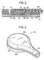
- FIG. 2is a partial cross-sectional view of the patch and sensor cable assembly of FIG. 1 through line A-A.
- FIG. 3is a perspective view of the strain relief element for use in patch and sensor cable assembly of FIG. 1 .
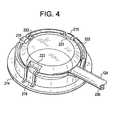
- FIG. 4is a perspective view of a patch and sensor cable connector.
- FIG. 5is a planar view of the top of a further patch and sensor cable assembly .
- FIG. 6is a cross-sectional view of the patch and sensor cable assembly of FIG. 5 .
- FIG. 7is a planar view of a disposable portion of a patch and sensor cable assembly.
- FIG. 8is an exploded view of the disposable portion of the patch and sensor cable assembly of FIG. 7 .
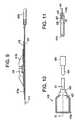
- FIG. 9is a cross-sectional view of the disposable portion of the patch and sensor cable assembly of FIG. 7 through line L-L.
- FIG. 10is a planar top view of the reusable sensor cable assembly for use in the patch assembly of FIG. 7
- FIG. 11is a cross-sectional view of the reusable sensor cable assembly through line A-A of FIG. 10 .
- FIG. 1depicts a planar view of an embodiment of the patch and sensor cable assembly in accordance with the present invention.
- the patch and sensor assembly 100comprises two major components: a patch assembly 110 and a sensor cable assembly 130.
- Sensor cable assembly 130comprises a sensor housing 122 that is adapted to connect to the patch assembly 110 and a sensor cable 124.
- the connection between the sensor housing 122 and patch assembly 110is a snap-fit based on the engagement of ridge 123 of sensor housing 122 and the lip of engagement element 114 of patch assembly 110.
- Patch assembly 110comprises a foam disk 112 having a plurality of indentations 113 adapted to receive the sensor cable 124.
- FIG. 1is shown with three such indentations enabling a user to attach the sensor cable assembly in one of three positions even after the disposable patch assembly has been placed on the patient.
- One or more such indentations 113may be used with the upper limit constrained by the ability of the remaining engagement element 114 to securely engage the ridge 123 of sensor housing 122 .
- Engagement element 114contains indentations that match those in foam disk 112 .
- the foam used to form foam disk 112may be any suitable material such as thermofoam, any elastomers like rubbber, santoprene, polyurethane etc. and is preferably thermofoam.
- FIG. 2depicts a partial cross-section of the patch and sensor assembly of FIG. 1 taken through line 2-2.
- Foam disk 112rests on a carbon film disk 116 coated with a layer of silver chloride on both sides.
- Carbon film disk 116is approximately 0.5 mm in thickness and the layer of silver chloride is approximately 0.1 mm in thickness. Other thicknesses of carbon film disk 116 and silver chloride coating may be used.
- On the patient facing side of carbon film disk 116is a hydrogel layer 117 .
- Hydrogel layer 117is comprised of a conductive gel medium, which also has adhesive properties to the skin, preferably a hydrogel being a mix of Silver/Silver Chloride with water based compound and is approximately 1mm mm in thickness.
- Foam disk 112 , carbon film disk 116 and the hydrogel layer 117generally have approximately the same diameter which should be large enough to provide a secure attachment to the body surface of the patient and is preferably between 4 cm and 16 cm.
- the only other component of patch assembly 110is the engagement element 114 .
- Patch assembly 110comprises only low-cost components in order to increase the disposability of the patch assembly in this embodiment.
- the other component of the patch and sensor assembly 100 depicted in FIGS. 1 and 2is the reusable sensor cable assembly 130 .
- the reusable sensor cable assembly 130comprises the aforementioned sensor housing 122.
- Sensor housing 122is a two-piece design in which upper housing portion 122a is designed to fit together with lower housing portion 122b.
- Lower housing portion 122bcontains the ridge 123 that engages engagement element 114 of the patch assembly although this ridge could be disposed on the upper housing portion without departing from the spirit of the present invention.
- Sensor housing 122is comprised of a polymer such as ABS, nylon, polypropylene or other suitable polymer known in the art and is preferably made from polypropylene.
- Sensor housing 122could be comprised of more than two parts.
- Sensor cable assembly 130further comprises the sensor cable 124 which comprises a conductive ACL cable made of a conductive and flexible material, preferably 28 gauge braided copper wire, three twisted pair conductors for the biosensor has along with two Kevlar fibers for added strength inside a polymeric outer sheath.
- One wire in sensor cable 124is welded or bonded using a conductive epoxy to biosensor 126 .
- Sensor cable assembly 130further comprises active current location (ACL) disk 134 which may be made of a suitably conductive material and is preferably a generally circular carbon disk coated with silver chloride. Gold or platinum may also be used instead of silver chloride for the coating and the carbon disk could be replaced with a polymer such as ABS or polycarbonate with or without carbon fibers embedded therein.
- ACL cable 136is attached to ACL sensor 134 using a suitable conductive epoxy, preferably any epoxy preferably embedded silver particles.
- current flowing through the patientis conducted through the hydrogel layer 117, carbon film disk 116 to ACL sensor 134 and through ACL cable 136 to the localization and mapping system that uses the ACL information to perform localization and mapping functions in accordance with United States Patent Application No. 2007/0016007 filed by Govari or other such similar system.
- Sensor cable assembly 130further comprises biosensor 126 which is a biosensor implemented in accordance with one or more of U.S. Pat. Nos. 5,391,199 , 5,443,489 , 6,788,967 and 6,690,963 to Ben-Haim .
- Magnetic field based information from biosensor 126is an electrical current induced by the magnetic field in which the patient is placed and is used in a manner similar to that used in the CartoTM EP mapping systems manufactured and sold by Biosense Webster, Inc.
- the electrical current from biosensor 126is conducted through three twisted pair conductors of the sensor cable assembly 130 to biosensor cable which connects to and EP mapping and localization system where the information is used.
- Biosensor 126is housed in biosensor housing 138 .
- Isolation layer 139is thin piece of plastic material preferably polypropylene, ABS or polycarbonate which isolates the 4KV defibrillation pulse from ACL wire to the biosensor 126.
- the biosensor 126 , ACL sensor 134 and the sensor cable 124 in the reusable sensor cable assembly 130is advantageous to have the biosensor 126 , ACL sensor 134 and the sensor cable 124 in the reusable sensor cable assembly 130 in order to reduce the cost of the disposable patch assembly 110 .
- the sensor cable assembly 130is connected to the patch assembly using an easy to operate snap-fit connection. This force will hold the re-usable to the disposable part.
- the sensor cable assemblymay be positioned in one of several orientations around the central axis of the patch assembly but rotation is prohibited by the combination of the engagement element 114 and the matching indentations in the foam disk 112 .
- FIG. 3depicts a perspective view of the sensor housing 122 showing the upper sensor housing 122a , the lower sensor housing 122b and the ridge 123.
- Sensor assembly 122preferably includes the strain relief element 125 but may also be substantial circular without such element.
- Strain relief element 125may be integral with sensor housing 122 or may comprise a separate polymeric sleeve that covers a portion of sensor cable 124 .
- FIG. 4depicts a perspective view of a further patch and sensor cable connector not in accordance with the present invention.
- Sensor housing 222has a plurality of indentations 223 which are adapted to engage under flexible engagement members 215 which form a portion of engagement element 214 .
- sensor housing 222forms a part of a sensor cable assembly 230 and engagement element 214 form a part of the patch assembly 110 .
- Engagement element 214is made from a polymer that is sufficiently flexible to enable flexible engagement members 215 to be pushed toward the periphery while the sensor cable assembly 230 is inserted into the engagement element 214 .
- the snap of re-usable to disposable partis held using a cantilever beam tab.
- the disposable partwill have the lever which deflects during the snapping operation. The normal forces exherted from the cantilever beam hold the snap together.
- FIGS. 5 and 6depict a planar top view and cross sectional view of another patch and sensor assembly not in accordance with the present invention.
- Patch and sensor assembly 300comprises two portions: a patch cable assembly 310 and a sensor cable assembly 330 .
- Patch cable assembly 310comprises a foam disk 312 having indentation 313 (with portions 313a and 313b ) to accommodate the sensor housing 322 and engagement element 314 .
- Two separate cablesare used to connect the biosensor and ACL sensor to the mapping and localization system.
- ACL cable 334is used to connect the ACL sensor layer 316 to the system for transmittal of current information to the localization system.
- the ACL cable 334can be substantially shorter than the length necessary to reach to the mapping and localization system and can be adapted to have a fitting that is designed to connect to a mated fitting on a cable that is collinear with the sensor cable.
- the fitting on the ACL cableis attached to the fitting on the additional cable that forms part of the sensor cable.
- ACL cable 334is stranded 28 gauge wire that is sandwiched between the foam disk 312 and the ACL sensor layer 316 .
- ACL sensor layer 316is a silver chloride coated carbon film of approximately 1mm with a silver chloride coating of approximately 0.5 mm.
- Below the ACL sensor layer 316is a hydrogel layer 317 substantially the same as the one described above with respect to the other embodiment.
- Figure 5has the snap feature in the form of three legs. This feature also works similar to principle of cantilever beam of Fig. 4 .
- the legsdeflect on the reusable part conforming to the opening on the disposable side. When snapped the beam expands providing the normal force to hold the two parts together.
- Sensor cable assembly 330comprises the engagement element 314, sensor housing 322 with biosensor 326 mounted inside.
- Sensor cable 324is used to connect the biosensor 326 that provides magnetic based localization information to the system.
- Sensor cable 324is a 48 gauge braided copper wire coated with a protective polymer with an exposed end welded or bonded, preferably using a conductive epoxy to the biosensor 326.
- Strain relief element 325covers a portion of the sensor cable 324 in order to reduce mechanical stress on the connection of the sensor cable to the biosensor and sensor housing.
- Biosensor 326is substantially similar to biosensor 126 for the embodiment described above.
- Engagement element 314is a mechanical snap designed to engage patch cable assembly 310.
- Engagement element 314has moveable elements 314a and 314b that are depressed in order to release and/or engage the engagement element onto the patch assembly.
- FIGS. 7-11depict the disposable patch cable assembly 410 comprising hydrogel layer 417 which is exposed for adhesion to the patient after removal of release liner 411.
- Hydrogel layer 417is preferably a hydrogel such as Amgel AG603 and is approximately 0.025 inch in thickness.
- Release liner 411is approximately 4.5 inches square and is comprised of 0.005 inch thick polyethylene terephthalate (PET) with a silicone coating on the side facing the hydrogel layer 417.
- PETpolyethylene terephthalate
- ACL sensor layer 416which is a carbon silver chloride disk.
- ACL sensor layer 416has a base material of conductive carbon and medical grade polyvinyl chloride (PVC) of approximately 0.004 inch in thickness with a patient facing (bottom) coating of silver-chloride and a top coating of silver both approximately 0.001 inch in thickness.
- PVCpolyvinyl chloride
- Cable assembly 434In electrical contact with ACL sensor layer 416 is the distal end of the cable assembly 434 which is placed under sensor engagement element 414 .
- Cable assembly 434is comprised of a 19 strands of tin plated copper wire which are stripped at the distal end 434a and fanned out to provide contact with the top side of the ACL sensor layer 416.
- Cable assembly 434should be covered with a jacket and meet requirements of all ANSI standards related to cables for medical devices.
- the proximal end of the cable assembly 434bshould have a socket assembly which is adapted to connect to the mapping and localization system or an interface cable for such a system for which it is adapted.
- the overall length of cable assembly 434is approximately 36 inches.
- Sensor engagement element 414is made of Lexan ® material or other polycarbonate material and is adapted to receive the distal end of the sensor cable assembly which is adapted to fit under lip 414a and be secured by prongs 414b.
- Foam disk 412ais a circular disk of approximately 0.005 inch thick white polyethylene foam with a medical grade acrylic pressure sensitive adhesive on its patient facing side and adheres to sensor engagement element 414, the distal end of the cable assembly 434 and a portion of the ACL sensor layer 416.
- Foam disk 412bis a circular foam disk with a plurality of indentations for structural integrity and one for placement of the sensor cable 424.
- Foam disk 412bhas an adhesive on its patient facing side that causes it to adhere to the top side of foam disk 412a.
- Foam disk 412bis comprised of white volara type-A closed cell polyethylene foam or an equivalent.
- FIGS. 10-11depict the reusable sensor cable assembly 430 for use with the patch cable assembly of FIGS. 7-9 .
- Sensor cable assembly 430comprises the engagement elements 414c and 414d , sensor housing 422 with biosensor 426 mounted inside.
- Sensor cable 424is used to connect the biosensor 426 that provides magnetic based localization information to the mapping and localization system (such as the Carto® system described herein) through a connector 428 .
- Sensor cable 424is a 48 gauge braided copper wire coated with a protective polymer with an exposed end welded or bonded, preferably using a conductive epoxy 427 to the biosensor 426 .
- Strain relief element 425covers a portion of the sensor cable 424 in order to reduce mechanical stress on the connection of the sensor cable to the biosensor and sensor housing.
- Biosensor 426is substantially similar to biosensor 126 for the embodiment described above.
- Engagement element 414cis an indentation in the top of the sensor housing substantially around the circumference of the housing and which is designed to engage the lip 414a of sensor engagement element of the patch cable assembly 410 .
- Engagement element 414dis an indentation in the proximal end of the bottom of the sensor housing 422 that are adapted to engage prongs 414b of patch cable assembly 410 in a snap-fit manner.
Landscapes
- Health & Medical Sciences (AREA)
- Life Sciences & Earth Sciences (AREA)
- Engineering & Computer Science (AREA)
- Heart & Thoracic Surgery (AREA)
- Molecular Biology (AREA)
- Biophysics (AREA)
- Pathology (AREA)
- Biomedical Technology (AREA)
- Veterinary Medicine (AREA)
- Medical Informatics (AREA)
- Physics & Mathematics (AREA)
- Surgery (AREA)
- Animal Behavior & Ethology (AREA)
- General Health & Medical Sciences (AREA)
- Public Health (AREA)
- Human Computer Interaction (AREA)
- Measurement And Recording Of Electrical Phenomena And Electrical Characteristics Of The Living Body (AREA)
- Electrotherapy Devices (AREA)
- Endoscopes (AREA)
Description
- The present invention relates to mechanisms for the attaching a reusable cable and housing containing a biosensor for magnetic field based localization to a conductive and adhesive patch assembly having at an electrode used for electrical and mechanical contact with the body surface of a patient. More particularly, the invention relates to a patch and cable attachment mechanism optimized for use in an electrophysiology mapping and ablation system using both biosensors and electrodes for magnetic and impedance or current based localization and mapping of medical devices in the human body.
- Many abnormal medical conditions in humans and other mammals have been associated with disease and other aberrations along the lining or walls that define several different body spaces. In order to treat such abnormal conditions of the body spaces, medical device technologies adapted for delivering various therapies to the body spaces using the least invasive means possible.
- As used herein, the term "body space," including derivatives thereof, is intended to mean any cavity within the body which is defined at least in part by a tissue wall. For example, the cardiac chambers, the uterus, the regions of the gastrointestinal tract, and the arterial or venous vessels are all considered illustrative examples of body spaces within the intended meaning.
- The term "vessel," including derivatives thereof, is herein intended to mean any body space which is circumscribed along a length by a tubular tissue wall and which terminates at each of two ends in at least one opening that communicates externally of the body space. For example, the large and small intestines, the vas deferens, the trachea, and the fallopian tubes are all illustrative examples of vessels within the intended meaning. Blood vessels are also herein considered vessels, including regions of the vascular tree between their branch points. More particularly, the pulmonary veins are vessels within the intended meaning, including the region of the pulmonary veins between the branched portions of their ostia along a left ventricle wall, although the wall tissue defining the ostia typically presents uniquely tapered lumenal shapes.
- One means of treating body spaces in a minimally invasive manner is through the use of catheters to reach internal organs and vessels within a body space. Electrode or electrophysiology (EP) catheters have been in common use in medical practice for many years. They are used to stimulate and map electrical activity in the heart and to ablate sites of aberrant electrical activity. In use, the electrode catheter is inserted into a major vein or artery, e.g., the femoral artery, and then guided into the chamber of the heart that is of concern in order to perform mapping and ablation procedures. It is important to know and be able to map the location of the tip or other portions of such electrode catheters within the vessels or other locations in the body space.
U.S. Pat. Nos. 5,391,199 ,5,443,489 ,6,788,967 and6,690,963 to Ben-Haim describe systems wherein the coordinates of an intrabody probe are determined using one or more field sensors, such as a Hall effect device, coils, or other antennae carried on the probe. Such systems are used for generating three-dimensional location information regarding a medical probe or catheter. Preferably, a sensor coil is placed in the catheter and generates signals in response to externally applied magnetic fields. The magnetic fields are generated by three radiator coils, fixed to an external reference frame in known, mutually spaced locations. The amplitudes of the signals generated in response to each of the radiator coil fields are detected and used to compute the location of the sensor coil. Each radiator coil is preferably driven by driver circuitry to generate a field at a known frequency, distinct from that of other radiator coils, so that the signals generated by the sensor coil may be separated by frequency into components corresponding to the different radiator coils.- In United States Patent Application No.
2007/0016007 filed by Govari , a hybrid position sensing system includes a probe adapted to be introduced into a body cavity of a subject. The probe includes a biosensor having a magnetic field transducer and at least one probe electrodes. A control unit is configured to measure position coordinates of the probe using the magnetic field transducer of the biosensor. The control unit also measures an impedance between the at least one probe electrodes and one or more points on a body surface of the subject. Using the measured position coordinates, the control unit calibrates the measured impedance. - Thus, in such a hybrid magnetic and impedance based systems, a biosensor and electrode must be placed at multiple points on the boy surface of the patient. Because the biosensors and the electrical cabling connecting them to the EP mapping system are relatively expensive, it is ideal that the biosensors and the associated cable be reusable. The portion attached to the skin is preferably disposable, therefore, a disposable patch is necessary for affixing the reusable biosensor and possibly a portion of the electrode to the skin of the patient.
- Existing patches comprises one or more stainless steel studs, foam and a conductive adhesive gel that is in contact with the skin of the patient. The matching patch cable in existing systems primarily comprise one or more matching stainless steel snaps into which the studs of the patch mate, a biosensor and the associated electrical cable all housed in an epoxy shell. Existing biosensor cable and patch mechanisms are radiopaque, i.e., the stainless steel snaps and studs appear on fluoroscopy. When multiple snaps are used which is often the case in order to provide a secure and non-rotating connection between the patch and the sensor cable, the multiple snaps do not allow the patch to take the shape of the body. Also, the patches are often large and conflict with other patches used on the body for ECG, defibrillators, intra-cardiac echograms, etc.
- Prior art mechanisms do not provide an adequate solution. For example,
U.S. Patent No. 3,606,881 , relates to a disposable patch having a metallic terminal with an enlarged head which permits a squeeze activated clip to be secured around the metallic terminal.U,S. Patent No. 3,829,826 provides a mechanical mechanism for attaching to the standard male metallic snap of the standard ECG patch. U.S. Patent No. 4,490,005 relates to a patch in which the central stud is a metal coated non-metallic substrate and which permits rotation of the sensor cable while reducing the effect of rotation on the metal to metal connection.U.S. Patent No. 4,635,642 relates to a disposable pad in which a conductive, preferably, silver coated metallic stud is inserted in order to make electrical conduct with a gel matrix that is in contact with the skin of the patient.- A similar conductively coated electrically conductive plastic is provided in
U.S. Patent No. 5,499,628 as an eyelet that is press fit into a terminal made of a resilient nonmetallic composition such as polypropylene blended with carbon fiber. U.S. Patent No. 5,615,674 relates to a clamping contact connection for contacting a fetal scalp probe.U.S. Patent No. 5,782,761 relates to a molded electrode one-piece and two-piece constructions for a molded electrode made of a conductive material such as a carbon-filled plastic.U.S. Patent No. 6,650,922 relates to an electrode element made of an electrode made of a biodegradable material that is also electro conductive.U.S. Patent No. 6,780,065 relates to a device for electrical connection of the power lead to an electrode for use on the skin.U. S. Patent No 7,226,299 relates to a circular electrical connector that engages the socket of a female connector that may include a locking device having resilient prongs.- Design Patent 240,166 relates to a medical electrode with a rectangular cube portion.
U.S. Patent Application Publication No. 2006/0167354 relates to a system for connecting an electrode to a conductive cable.U.S. Patent Application Publication No. 2006/0149146 relates to a device having an electrode for contact with the patient and a pressure sensor.U.S. Patent No. 5,978,693 relates to an electrode having a deformation sensor such as a strain gauge.US 4,653,503 discloses physiological electrodes for use with a magnetic connector to complete an electrical circuit between the body of a patient and an electrical instrument. The electrodes contain a ferromagnetic material to complete a magnetic circuit with a magnetic member on an associated lead wire. The ferromagnetic material is included in an electrically conductive electrode element that contains an electrically conductive material, such as a saline gel, and the ferromagnetic material is isolated from the electrically conductive medium to prevent corrosion. The electrodes are provided with an arrangement for securing the electrode element to the body of a patient, and a separating member is provided to prevent the electrically conductive electrode element from contacting the skin of the patient in certain applications.WO 92/08407 US 5,879,373 discloses a system for determining the properties of tissue parts of a living organism, comprising an optoelectronic measuring device and an attachment device which is opaque to light and surrounds a measuring window through which determinations are carried out. The device has one or several components for reproducibly attaching the measuring device in a direction toward a first surface of the tissue.US 4,947,846 discloses a waterproof electrode device for a living body. The device is characterised by a construction in which a magnet is provided either to a connector or an ECG electrode, and a magnetic material of a magnet to the other, and both are stuck by magnetic attraction. A sealing material comprising a closed-cell foam is interposed between an electrode case and the connector. Owing to the construction, electric signals do not leak into surrounding water and the connector is not pressed against the electrode.- It is an object of the present invention to provide a patch that is generally not visible under fluoroscopy.
- It is a further object of the present invention that the patch be capable of being smaller than currently used patches so as to minimize the amount of space used on the skin of the patient and reduce potential conflict with other patches.
- Additionally, it is an object of the present invention to provide a patch and sensor cable that will not rotate as would previous designs utilizing a single snap.
- Furthermore, it is an object of the present invention to have a patch and sensor cable attachment mechanism that is easy to attach.
- Additionally, it is an object of the present invention to have a patch and sensor cable design that could be used for ECG or other instrument systems.
- Finally, it is an object of the present invention to have a patch and sensor cable attachment mechanism that enables repeated reuse of the biosensor and sensor cable without any degradation in performance.
- The present invention provides a disposable patch assembly as claimed hereinafter in independent claim 1 and the dependent claims 2-7.
- The engagement element may be made of a polycarbonate, preferably Lexan® polycarbonate.
- The electrical leads of the disposable patch assembly and the reusable sensor assembly can be connected to a device mapping and localization system such as the Carto® system.
FIG. 1 is a planar view of the top of the patch and sensor cable assembly in accordance with a first embodiment of the present invention.FIG. 2 is a partial cross-sectional view of the patch and sensor cable assembly ofFIG. 1 through line A-A.FIG. 3 is a perspective view of the strain relief element for use in patch and sensor cable assembly ofFIG. 1 .FIG. 4 is a perspective view of a patch and sensor cable connector.FIG. 5 is a planar view of the top of a further patch and sensor cable assembly .FIG. 6 is a cross-sectional view of the patch and sensor cable assembly ofFIG. 5 .FIG. 7 is a planar view of a disposable portion of a patch and sensor cable assembly.FIG. 8 is an exploded view of the disposable portion of the patch and sensor cable assembly ofFIG. 7 .FIG. 9 is a cross-sectional view of the disposable portion of the patch and sensor cable assembly ofFIG. 7 through line L-L.FIG. 10 is a planar top view of the reusable sensor cable assembly for use in the patch assembly ofFIG. 7 FIG. 11 is a cross-sectional view of the reusable sensor cable assembly through line A-A ofFIG. 10 .- Referring to the drawings,
FIG. 1 depicts a planar view of an embodiment of the patch and sensor cable assembly in accordance with the present invention. As shown inFIG. 1 , the patch andsensor assembly 100 comprises two major components: apatch assembly 110 and asensor cable assembly 130.Sensor cable assembly 130 comprises asensor housing 122 that is adapted to connect to thepatch assembly 110 and asensor cable 124. InFIG. 1 the connection between thesensor housing 122 andpatch assembly 110 is a snap-fit based on the engagement ofridge 123 ofsensor housing 122 and the lip ofengagement element 114 ofpatch assembly 110.Patch assembly 110 comprises afoam disk 112 having a plurality ofindentations 113 adapted to receive thesensor cable 124. The patch assembly inFIG. 1 is shown with three such indentations enabling a user to attach the sensor cable assembly in one of three positions even after the disposable patch assembly has been placed on the patient. One or moresuch indentations 113 may be used with the upper limit constrained by the ability of the remainingengagement element 114 to securely engage theridge 123 ofsensor housing 122.Engagement element 114 contains indentations that match those infoam disk 112. The foam used to formfoam disk 112 may be any suitable material such as thermofoam, any elastomers like rubbber, santoprene, polyurethane etc. and is preferably thermofoam. FIG. 2 depicts a partial cross-section of the patch and sensor assembly ofFIG. 1 taken through line 2-2.Foam disk 112 rests on a carbon film disk116 coated with a layer of silver chloride on both sides. Carbon film disk 116 is approximately 0.5 mm in thickness and the layer of silver chloride is approximately 0.1 mm in thickness. Other thicknesses of carbon film disk116 and silver chloride coating may be used. On the patient facing side of carbon film disk116 is ahydrogel layer 117.Hydrogel layer 117 is comprised of a conductive gel medium, which also has adhesive properties to the skin, preferably a hydrogel being a mix of Silver/Silver Chloride with water based compound and is approximately 1mm mm in thickness.Foam disk 112, carbon film disk116 and thehydrogel layer 117 generally have approximately the same diameter which should be large enough to provide a secure attachment to the body surface of the patient and is preferably between 4 cm and 16 cm. The only other component ofpatch assembly 110 is theengagement element 114.Patch assembly 110 comprises only low-cost components in order to increase the disposability of the patch assembly in this embodiment.- The other component of the patch and
sensor assembly 100 depicted inFIGS. 1 and2 is the reusablesensor cable assembly 130. The reusablesensor cable assembly 130 comprises theaforementioned sensor housing 122.Sensor housing 122 is a two-piece design in whichupper housing portion 122a is designed to fit together withlower housing portion 122b.Lower housing portion 122b contains theridge 123 that engagesengagement element 114 of the patch assembly although this ridge could be disposed on the upper housing portion without departing from the spirit of the present invention.Sensor housing 122 is comprised of a polymer such as ABS, nylon, polypropylene or other suitable polymer known in the art and is preferably made from polypropylene.Sensor housing 122 could be comprised of more than two parts. Sensor cable assembly 130 further comprises thesensor cable 124 which comprises a conductive ACL cable made of a conductive and flexible material, preferably 28 gauge braided copper wire, three twisted pair conductors for the biosensor has along with two Kevlar fibers for added strength inside a polymeric outer sheath. One wire insensor cable 124 is welded or bonded using a conductive epoxy tobiosensor 126.Sensor cable assembly 130 further comprises active current location (ACL)disk 134 which may be made of a suitably conductive material and is preferably a generally circular carbon disk coated with silver chloride. Gold or platinum may also be used instead of silver chloride for the coating and the carbon disk could be replaced with a polymer such as ABS or polycarbonate with or without carbon fibers embedded therein.ACL cable 136 is attached toACL sensor 134 using a suitable conductive epoxy, preferably any epoxy preferably embedded silver particles. In use, current flowing through the patient is conducted through thehydrogel layer 117, carbon film disk 116 toACL sensor 134 and throughACL cable 136 to the localization and mapping system that uses the ACL information to perform localization and mapping functions in accordance with United States Patent Application No.2007/0016007 filed by Govari or other such similar system.Sensor cable assembly 130 further comprisesbiosensor 126 which is a biosensor implemented in accordance with one or more ofU.S. Pat. Nos. 5,391,199 ,5,443,489 ,6,788,967 and6,690,963 to Ben-Haim . Magnetic field based information frombiosensor 126 is an electrical current induced by the magnetic field in which the patient is placed and is used in a manner similar to that used in the Carto™ EP mapping systems manufactured and sold by Biosense Webster, Inc. The electrical current frombiosensor 126 is conducted through three twisted pair conductors of thesensor cable assembly 130 to biosensor cable which connects to and EP mapping and localization system where the information is used.Biosensor 126 is housed inbiosensor housing 138.Isolation layer 139 is thin piece of plastic material preferably polypropylene, ABS or polycarbonate which isolates the 4KV defibrillation pulse from ACL wire to thebiosensor 126.- As can be seen from
FIGS. 1 and2 , it is advantageous to have thebiosensor 126,ACL sensor 134 and thesensor cable 124 in the reusablesensor cable assembly 130 in order to reduce the cost of thedisposable patch assembly 110. Thesensor cable assembly 130 is connected to the patch assembly using an easy to operate snap-fit connection. This force will hold the re-usable to the disposable part. The sensor cable assembly may be positioned in one of several orientations around the central axis of the patch assembly but rotation is prohibited by the combination of theengagement element 114 and the matching indentations in thefoam disk 112. FIG. 3 depicts a perspective view of thesensor housing 122 showing theupper sensor housing 122a, thelower sensor housing 122b and theridge 123.Sensor assembly 122 preferably includes thestrain relief element 125 but may also be substantial circular without such element.Strain relief element 125 may be integral withsensor housing 122 or may comprise a separate polymeric sleeve that covers a portion ofsensor cable 124.FIG. 4 depicts a perspective view of a further patch and sensor cable connector not in accordance with the present invention.Sensor housing 222 has a plurality ofindentations 223 which are adapted to engage underflexible engagement members 215 which form a portion ofengagement element 214. As in the previous embodiment described above,sensor housing 222 forms a part of asensor cable assembly 230 andengagement element 214 form a part of thepatch assembly 110.Engagement element 214 is made from a polymer that is sufficiently flexible to enableflexible engagement members 215 to be pushed toward the periphery while thesensor cable assembly 230 is inserted into theengagement element 214. The snap of re-usable to disposable part is held using a cantilever beam tab. The disposable part will have the lever which deflects during the snapping operation. The normal forces exherted from the cantilever beam hold the snap together.FIGS. 5 and6 depict a planar top view and cross sectional view of another patch and sensor assembly not in accordance with the present invention. Patch andsensor assembly 300 comprises two portions: apatch cable assembly 310 and asensor cable assembly 330.Patch cable assembly 310 comprises afoam disk 312 having indentation313 (withportions sensor housing 322 andengagement element 314. Two separate cables are used to connect the biosensor and ACL sensor to the mapping and localization system.ACL cable 334 is used to connect theACL sensor layer 316 to the system for transmittal of current information to the localization system. Alternatively, theACL cable 334 can be substantially shorter than the length necessary to reach to the mapping and localization system and can be adapted to have a fitting that is designed to connect to a mated fitting on a cable that is collinear with the sensor cable. In the configuration, the fitting on the ACL cable is attached to the fitting on the additional cable that forms part of the sensor cable. In this manner, a substantial length of the ACL cable becomes part of the reusable sensor cable assembly.ACL cable 334 is stranded28 gauge wire that is sandwiched between thefoam disk 312 and theACL sensor layer 316.ACL sensor layer 316 is a silver chloride coated carbon film of approximately 1mm with a silver chloride coating of approximately 0.5 mm. Below theACL sensor layer 316 is ahydrogel layer 317 substantially the same as the one described above with respect to the other embodiment.Figure 5 has the snap feature in the form of three legs. This feature also works similar to principle of cantilever beam ofFig. 4 . The legs deflect on the reusable part conforming to the opening on the disposable side. When snapped the beam expands providing the normal force to hold the two parts together.Sensor cable assembly 330 comprises theengagement element 314,sensor housing 322 withbiosensor 326 mounted inside.Sensor cable 324 is used to connect thebiosensor 326 that provides magnetic based localization information to the system.Sensor cable 324 is a 48 gauge braided copper wire coated with a protective polymer with an exposed end welded or bonded, preferably using a conductive epoxy to thebiosensor 326.Strain relief element 325 covers a portion of thesensor cable 324 in order to reduce mechanical stress on the connection of the sensor cable to the biosensor and sensor housing.Biosensor 326 is substantially similar tobiosensor 126 for the embodiment described above.Engagement element 314 is a mechanical snap designed to engagepatch cable assembly 310.Engagement element 314 hasmoveable elements - An alternative patch and sensor cable assembly not in accordance with the present invention is depicted in
FIGS. 7-11. FIGS. 7-9 depict the disposablepatch cable assembly 410 comprisinghydrogel layer 417 which is exposed for adhesion to the patient after removal ofrelease liner 411.Hydrogel layer 417 is preferably a hydrogel such as Amgel AG603 and is approximately 0.025 inch in thickness.Release liner 411 is approximately 4.5 inches square and is comprised of 0.005 inch thick polyethylene terephthalate (PET) with a silicone coating on the side facing thehydrogel layer 417. Abovehydrogel layer 417 isACL sensor layer 416 which is a carbon silver chloride disk. More specifically,ACL sensor layer 416 has a base material of conductive carbon and medical grade polyvinyl chloride (PVC) of approximately 0.004 inch in thickness with a patient facing (bottom) coating of silver-chloride and a top coating of silver both approximately 0.001 inch in thickness. - In electrical contact with
ACL sensor layer 416 is the distal end of thecable assembly 434 which is placed undersensor engagement element 414.Cable assembly 434 is comprised of a 19 strands of tin plated copper wire which are stripped at thedistal end 434a and fanned out to provide contact with the top side of theACL sensor layer 416.Cable assembly 434 should be covered with a jacket and meet requirements of all ANSI standards related to cables for medical devices. The proximal end of thecable assembly 434b should have a socket assembly which is adapted to connect to the mapping and localization system or an interface cable for such a system for which it is adapted. The overall length ofcable assembly 434 is approximately 36 inches.Sensor engagement element 414 is made of Lexan ® material or other polycarbonate material and is adapted to receive the distal end of the sensor cable assembly which is adapted to fit underlip 414a and be secured byprongs 414b.Foam disk 412a is a circular disk of approximately 0.005 inch thick white polyethylene foam with a medical grade acrylic pressure sensitive adhesive on its patient facing side and adheres tosensor engagement element 414, the distal end of thecable assembly 434 and a portion of theACL sensor layer 416.Foam disk 412b is a circular foam disk with a plurality of indentations for structural integrity and one for placement of thesensor cable 424.Foam disk 412b has an adhesive on its patient facing side that causes it to adhere to the top side offoamdisk 412a.Foam disk 412b is comprised of white volara type-A closed cell polyethylene foam or an equivalent. FIGS. 10-11 depict the reusablesensor cable assembly 430 for use with the patch cable assembly ofFIGS. 7-9 .Sensor cable assembly 430 comprises theengagement elements sensor housing 422 withbiosensor 426 mounted inside.Sensor cable 424 is used to connect thebiosensor 426 that provides magnetic based localization information to the mapping and localization system (such as the Carto® system described herein) through aconnector 428.Sensor cable 424 is a 48 gauge braided copper wire coated with a protective polymer with an exposed end welded or bonded, preferably using aconductive epoxy 427 to thebiosensor 426.Strain relief element 425 covers a portion of thesensor cable 424 in order to reduce mechanical stress on the connection of the sensor cable to the biosensor and sensor housing.Biosensor 426 is substantially similar tobiosensor 126 for the embodiment described above.Engagement element 414c is an indentation in the top of the sensor housing substantially around the circumference of the housing and which is designed to engage thelip 414a of sensor engagement element of thepatch cable assembly 410.Engagement element 414d is an indentation in the proximal end of the bottom of thesensor housing 422 that are adapted to engageprongs 414b ofpatch cable assembly 410 in a snap-fit manner.- The preceding description has been presented with reference to presently preferred embodiments of the invention. Workers skilled in the art and technology to which this invention pertains will appreciate that alterations and changes in the described structure may be practiced without meaningfully departing from the scope of this invention.
- Accordingly, the foregoing description should not be read as pertaining only to the precise structures described and illustrated in the accompanying drawings, but rather should be read consistent with and as support to the following claims which are to have their fullest and fair scope.
Claims (7)
- A disposable patch assembly (110) for use in a device mapping system used to map the location of a device within the body of a patient comprising:an adhesive layer (117) configured to adhere the disposable patch assembly to the body of the patient;an electrode layer (116) ;a foam layer (112) disposed on the electrode layer; and,an engagement element (114) adapted to detachably engage at least a portion (123) of a housing (122) of a reusable sensor cable assembly (130);characterized in that : the adhesive layer is an adhesive hydrogel layer; the electrode layer is disposed on the adhesive hydrogel layer; andwherein the foam layer has a plurality of indentations (113) adapted to receive a sensor cable (124) of the reusable sensor cable assembly.
- The disposable patch assembly (110) of claim 1, further comprising a cable (136) configured to communicate an electrical signal detected from the body of the patient to the device mapping system.
- The disposable patch assembly (110) of claim 2, wherein the cable (136) terminates between the electrode layer and the foam layer.
- The disposable patch assembly (110) of claim 1, wherein the foam layer (112) is comprised of thermofoam.
- The disposable patch assembly (110) of claim 1, wherein the engagement element (114) comprises an arcuate lip adapted to engage a ridge (123) on the housing (122) of the reusable sensor cable assembly (130) in a snap-fit manner.
- The disposable patch assembly (110) of claim 1, wherein the foam layer (112) has an opening adapted to receive a portion of the engagement element (114).
- A patch and sensor assembly (100) for use in a device mapping system used to map the location of a device within the body of a patient, the patch and sensor assembly comprising a reusable portion (130) and a disposable patch assembly (110) according to any preceding claim, the reusable portion comprising:a magnetic-based biosensor (126) configured to provide location information about the location of the device within the body of the patient to the device mapping system;a housing (122) adapted to house the biosensor;a first electrical lead (124) configured to communicate an electrical signal from the biosensor to the device mapping system.
Applications Claiming Priority (3)
| Application Number | Priority Date | Filing Date | Title |
|---|---|---|---|
| US12/144,826US9737225B2 (en) | 2008-06-24 | 2008-06-24 | Patch and sensor assembly for use in medical device localization and mapping systems |
| US12/256,580US9014778B2 (en) | 2008-06-24 | 2008-10-23 | Disposable patch and reusable sensor assembly for use in medical device localization and mapping systems |
| EP09748551AEP2328474B1 (en) | 2008-06-24 | 2009-06-19 | Patch and sensor assembly for use in medical device localization and mapping systems |
Related Parent Applications (1)
| Application Number | Title | Priority Date | Filing Date |
|---|---|---|---|
| EP09748551.0Division | 2009-06-19 |
Publications (2)
| Publication Number | Publication Date |
|---|---|
| EP2389860A1 EP2389860A1 (en) | 2011-11-30 |
| EP2389860B1true EP2389860B1 (en) | 2012-11-21 |
Family
ID=41431932
Family Applications (3)
| Application Number | Title | Priority Date | Filing Date |
|---|---|---|---|
| EP11178894AActiveEP2389860B1 (en) | 2008-06-24 | 2009-06-19 | Disposable patch and reusable sensor assembly for use in medical device localization and mapping systems |
| EP09748551AActiveEP2328474B1 (en) | 2008-06-24 | 2009-06-19 | Patch and sensor assembly for use in medical device localization and mapping systems |
| EP12177381.6AActiveEP2520223B1 (en) | 2008-06-24 | 2009-06-19 | Disposable patch and reusable sensor assembly for use in medical device localization and mapping systems |
Family Applications After (2)
| Application Number | Title | Priority Date | Filing Date |
|---|---|---|---|
| EP09748551AActiveEP2328474B1 (en) | 2008-06-24 | 2009-06-19 | Patch and sensor assembly for use in medical device localization and mapping systems |
| EP12177381.6AActiveEP2520223B1 (en) | 2008-06-24 | 2009-06-19 | Disposable patch and reusable sensor assembly for use in medical device localization and mapping systems |
Country Status (10)
| Country | Link |
|---|---|
| US (1) | US9014778B2 (en) |
| EP (3) | EP2389860B1 (en) |
| JP (1) | JP5666437B2 (en) |
| CN (1) | CN102159133B (en) |
| AU (1) | AU2009274436B2 (en) |
| CA (1) | CA2728536C (en) |
| DK (2) | DK2389860T3 (en) |
| ES (2) | ES2397692T3 (en) |
| IL (3) | IL210020A (en) |
| WO (1) | WO2010011450A2 (en) |
Families Citing this family (99)
| Publication number | Priority date | Publication date | Assignee | Title |
|---|---|---|---|---|
| US6850788B2 (en) | 2002-03-25 | 2005-02-01 | Masimo Corporation | Physiological measurement communications adapter |
| US20120016259A1 (en)* | 2003-12-23 | 2012-01-19 | Ib Rask Odderson | Nerve Path Adaptable Nerve Testing Device |
| EP3827747A1 (en) | 2005-04-28 | 2021-06-02 | Otsuka Pharmaceutical Co., Ltd. | Pharma-informatics system |
| US8802183B2 (en) | 2005-04-28 | 2014-08-12 | Proteus Digital Health, Inc. | Communication system with enhanced partial power source and method of manufacturing same |
| US8836513B2 (en) | 2006-04-28 | 2014-09-16 | Proteus Digital Health, Inc. | Communication system incorporated in an ingestible product |
| US8912908B2 (en) | 2005-04-28 | 2014-12-16 | Proteus Digital Health, Inc. | Communication system with remote activation |
| US9198608B2 (en) | 2005-04-28 | 2015-12-01 | Proteus Digital Health, Inc. | Communication system incorporated in a container |
| US8730031B2 (en) | 2005-04-28 | 2014-05-20 | Proteus Digital Health, Inc. | Communication system using an implantable device |
| US8547248B2 (en) | 2005-09-01 | 2013-10-01 | Proteus Digital Health, Inc. | Implantable zero-wire communications system |
| JP2009544338A (en) | 2006-05-02 | 2009-12-17 | プロテウス バイオメディカル インコーポレイテッド | Treatment regimen customized to the patient |
| EP2087589B1 (en) | 2006-10-17 | 2011-11-23 | Proteus Biomedical, Inc. | Low voltage oscillator for medical devices |
| SG175681A1 (en) | 2006-10-25 | 2011-11-28 | Proteus Biomedical Inc | Controlled activation ingestible identifier |
| US8718193B2 (en) | 2006-11-20 | 2014-05-06 | Proteus Digital Health, Inc. | Active signal processing personal health signal receivers |
| CN101686800A (en) | 2007-02-01 | 2010-03-31 | 普罗秋斯生物医学公司 | Ingestible Event Marker System |
| US8956288B2 (en) | 2007-02-14 | 2015-02-17 | Proteus Digital Health, Inc. | In-body power source having high surface area electrode |
| EP2063771A1 (en) | 2007-03-09 | 2009-06-03 | Proteus Biomedical, Inc. | In-body device having a deployable antenna |
| EP2124725A1 (en) | 2007-03-09 | 2009-12-02 | Proteus Biomedical, Inc. | In-body device having a multi-directional transmitter |
| US8115618B2 (en) | 2007-05-24 | 2012-02-14 | Proteus Biomedical, Inc. | RFID antenna for in-body device |
| DK2192946T3 (en) | 2007-09-25 | 2022-11-21 | Otsuka Pharma Co Ltd | In-body device with virtual dipole signal amplification |
| CN104376659B (en) | 2008-03-05 | 2019-10-25 | 普罗透斯数字保健公司 | The ingestible event flag of multi-modal communications and system, and the method using it |
| US7935039B2 (en)* | 2008-05-30 | 2011-05-03 | Jef Dannenberg | Muscle toner exercise apparatus |
| US9737225B2 (en) | 2008-06-24 | 2017-08-22 | Biosense Webster, Inc. | Patch and sensor assembly for use in medical device localization and mapping systems |
| AU2009268827B2 (en) | 2008-07-08 | 2013-10-24 | Proteus Digital Health, Inc. | Ingestible event marker data framework |
| MY154217A (en) | 2008-08-13 | 2015-05-15 | Proteus Digital Health Inc | Ingestible circuitry |
| US8036748B2 (en) | 2008-11-13 | 2011-10-11 | Proteus Biomedical, Inc. | Ingestible therapy activator system and method |
| EP2358270A4 (en) | 2008-12-11 | 2014-08-13 | Proteus Digital Health Inc | Evaluation of gastrointestinal function using portable electroviscerography systems and methods of using the same |
| US9659423B2 (en) | 2008-12-15 | 2017-05-23 | Proteus Digital Health, Inc. | Personal authentication apparatus system and method |
| TWI503101B (en) | 2008-12-15 | 2015-10-11 | Proteus Digital Health Inc | Body-associated receiver and method |
| US9439566B2 (en) | 2008-12-15 | 2016-09-13 | Proteus Digital Health, Inc. | Re-wearable wireless device |
| KR20110103446A (en) | 2009-01-06 | 2011-09-20 | 프로테우스 바이오메디컬, 인코포레이티드 | Intake-Related Biofeedback and Individualized Medical Treatment Methods and Systems |
| SG172847A1 (en) | 2009-01-06 | 2011-08-29 | Proteus Biomedical Inc | Pharmaceutical dosages delivery system |
| FR2940904B1 (en)* | 2009-01-13 | 2012-08-31 | Urgo Laboratoires | INTERFACE PRESSURE MEASURING SYSTEM |
| US9492105B1 (en)* | 2009-02-13 | 2016-11-15 | Cleveland Medical Devices Inc. | Device for sleep diagnosis |
| WO2010111403A2 (en) | 2009-03-25 | 2010-09-30 | Proteus Biomedical, Inc. | Probablistic pharmacokinetic and pharmacodynamic modeling |
| EP3906845A1 (en) | 2009-04-28 | 2021-11-10 | Otsuka Pharmaceutical Co., Ltd. | Highly reliable ingestible event markers |
| EP2432458A4 (en) | 2009-05-12 | 2014-02-12 | Proteus Digital Health Inc | Ingestible event markers comprising an ingestible component |
| US8558563B2 (en) | 2009-08-21 | 2013-10-15 | Proteus Digital Health, Inc. | Apparatus and method for measuring biochemical parameters |
| TWI517050B (en) | 2009-11-04 | 2016-01-11 | 普羅托斯數位健康公司 | System for supply chain management |
| UA109424C2 (en) | 2009-12-02 | 2015-08-25 | PHARMACEUTICAL PRODUCT, PHARMACEUTICAL TABLE WITH ELECTRONIC MARKER AND METHOD OF MANUFACTURING PHARMACEUTICAL TABLETS | |
| BR112012019212A2 (en) | 2010-02-01 | 2017-06-13 | Proteus Digital Health Inc | data collection system |
| WO2011127252A2 (en) | 2010-04-07 | 2011-10-13 | Proteus Biomedical, Inc. | Miniature ingestible device |
| TWI557672B (en) | 2010-05-19 | 2016-11-11 | 波提亞斯數位康健公司 | Computer system and computer-implemented method to track medication from manufacturer to a patient, apparatus and method for confirming delivery of medication to a patient, patient interface device |
| JP2014504902A (en) | 2010-11-22 | 2014-02-27 | プロテウス デジタル ヘルス, インコーポレイテッド | Ingestible device with medicinal product |
| US9375179B2 (en)* | 2010-12-23 | 2016-06-28 | Biosense Webster, Inc. | Single radio-transparent connector for multi-functional reference patch |
| WO2012125425A2 (en) | 2011-03-11 | 2012-09-20 | Proteus Biomedical, Inc. | Wearable personal body associated device with various physical configurations |
| WO2015112603A1 (en) | 2014-01-21 | 2015-07-30 | Proteus Digital Health, Inc. | Masticable ingestible product and communication system therefor |
| US9756874B2 (en) | 2011-07-11 | 2017-09-12 | Proteus Digital Health, Inc. | Masticable ingestible product and communication system therefor |
| PH12014500174A1 (en) | 2011-07-21 | 2024-02-12 | Proteus Digital Health Inc | Mobile communication device, system, and method |
| WO2013023041A2 (en)* | 2011-08-10 | 2013-02-14 | Aum Cardiovascular, Inc. | Devices, systems and methods for the detection of coronary artery disease |
| US9717811B2 (en)* | 2011-09-30 | 2017-08-01 | Avent, Inc. | Flexible multi-panel sterilization assembly with side tabs |
| US9235683B2 (en) | 2011-11-09 | 2016-01-12 | Proteus Digital Health, Inc. | Apparatus, system, and method for managing adherence to a regimen |
| IN2014DN10262A (en)* | 2012-06-19 | 2015-08-07 | Nestec Sa | |
| SG11201408382RA (en)* | 2012-06-29 | 2015-01-29 | Sunstar Suisse Sa | Gel pad dispenser |
| EP2874886B1 (en) | 2012-07-23 | 2023-12-20 | Otsuka Pharmaceutical Co., Ltd. | Techniques for manufacturing ingestible event markers comprising an ingestible component |
| EP2877239B1 (en)* | 2012-07-26 | 2023-06-21 | Nyxoah SA | Electrical contacts on a medical device patch |
| US9907967B2 (en) | 2012-07-26 | 2018-03-06 | Adi Mashiach | Transcutaneous power conveyance device |
| CN104755022B (en)* | 2012-10-04 | 2017-01-18 | Med-El电气医疗器械有限公司 | Electromechanical measurement of stapedius muscle/tendon activity |
| AU2013331417B2 (en) | 2012-10-18 | 2016-06-02 | Proteus Digital Health, Inc. | Apparatus, system, and method to adaptively optimize power dissipation and broadcast power in a power source for a communication device |
| US9703751B2 (en) | 2012-11-07 | 2017-07-11 | Nokia Technologies Oy | Apparatus and sensors for attachment to the apparatus |
| US10244986B2 (en) | 2013-01-23 | 2019-04-02 | Avery Dennison Corporation | Wireless sensor patches and methods of manufacturing |
| US11149123B2 (en) | 2013-01-29 | 2021-10-19 | Otsuka Pharmaceutical Co., Ltd. | Highly-swellable polymeric films and compositions comprising the same |
| WO2014144738A1 (en) | 2013-03-15 | 2014-09-18 | Proteus Digital Health, Inc. | Metal detector apparatus, system, and method |
| JP6498177B2 (en) | 2013-03-15 | 2019-04-10 | プロテウス デジタル ヘルス, インコーポレイテッド | Identity authentication system and method |
| KR101479745B1 (en) | 2013-05-08 | 2015-01-12 | 정용준 | A corrective apparatus for forward head posture |
| CN103239225A (en)* | 2013-05-13 | 2013-08-14 | 湛江市康田医用器械高科技有限公司 | Method for producing electrocardiograph monitoring electrodes |
| EP3005281A4 (en) | 2013-06-04 | 2017-06-28 | Proteus Digital Health, Inc. | System, apparatus and methods for data collection and assessing outcomes |
| US9796576B2 (en) | 2013-08-30 | 2017-10-24 | Proteus Digital Health, Inc. | Container with electronically controlled interlock |
| CA2965941C (en) | 2013-09-20 | 2020-01-28 | Proteus Digital Health, Inc. | Methods, devices and systems for receiving and decoding a signal in the presence of noise using slices and warping |
| WO2015044722A1 (en) | 2013-09-24 | 2015-04-02 | Proteus Digital Health, Inc. | Method and apparatus for use with received electromagnetic signal at a frequency not known exactly in advance |
| US10084880B2 (en) | 2013-11-04 | 2018-09-25 | Proteus Digital Health, Inc. | Social media networking based on physiologic information |
| CN104287739B (en)* | 2014-09-16 | 2016-08-31 | 苏州能斯达电子科技有限公司 | A kind of flexible wearable sensor detecting foot motion and preparation method thereof |
| CN104257359B (en)* | 2014-09-16 | 2016-04-06 | 苏州能斯达电子科技有限公司 | A kind of wearable flexible sensor of monitoring wrist pulse and preparation method thereof |
| CN104257366B (en)* | 2014-09-16 | 2016-06-01 | 苏州能斯达电子科技有限公司 | A kind of wearable physiology sign detecting sensor, preparation method and Monitoring systems thereof |
| US11051543B2 (en) | 2015-07-21 | 2021-07-06 | Otsuka Pharmaceutical Co. Ltd. | Alginate on adhesive bilayer laminate film |
| US11033201B2 (en)* | 2015-09-04 | 2021-06-15 | Biosense Webster (Israel) Ltd. | Inconsistent field-based patch location coordinate correction |
| TWI555509B (en)* | 2015-11-10 | 2016-11-01 | 鋐雩科技有限公司 | Electrode device for wearable or portable apparatus |
| TWI565446B (en)* | 2015-12-14 | 2017-01-11 | 準訊生醫股份有限公司 | Long term physiological signal sensing patch |
| CN206080497U (en)* | 2015-12-18 | 2017-04-12 | 上海温尔信息科技有限公司 | Attached formula cancer cell abnormal temperature probe of skin |
| WO2017146828A1 (en) | 2016-02-22 | 2017-08-31 | St. Jude Medical, Cardiology Division, Inc. | Adhesive patch for use with reusable medical devices |
| US10390759B2 (en) | 2016-02-25 | 2019-08-27 | Welch Allyn, Inc. | Physical assessment parameter measuring device |
| US11647934B2 (en) | 2016-05-06 | 2023-05-16 | Konan Medical Usa, Inc. | Mono-layer electrode sensor |
| US10966622B2 (en)* | 2016-05-20 | 2021-04-06 | The Board Of Trustees Of Western Michigan University | Printed ECG electrode and method |
| US10653331B2 (en) | 2016-05-24 | 2020-05-19 | Konan Medical Usa, Inc. | Electrode sensor |
| KR20210018961A (en) | 2016-07-22 | 2021-02-18 | 프로테우스 디지털 헬스, 인코포레이티드 | Electromagnetic sensing and detection of ingestible event markers |
| CN106422052A (en)* | 2016-10-25 | 2017-02-22 | 车绥元 | Defibrillation monitor conduction paster |
| CN109963499B (en) | 2016-10-26 | 2022-02-25 | 大冢制药株式会社 | Method for manufacturing capsules with ingestible event markers |
| GB2555640A (en)* | 2016-11-07 | 2018-05-09 | The Newcastle Upon Tyne Hospitals Nhs Found Trust | Sensor housing and associated disposable element |
| CN110913759A (en)* | 2017-03-08 | 2020-03-24 | 门塔拉布有限公司 | System for detecting biological signals |
| CN107014877B (en)* | 2017-05-27 | 2023-06-20 | 北京怡唐生物科技有限公司 | A dynamic continuous blood glucose monitoring system |
| US10596295B2 (en)* | 2017-08-28 | 2020-03-24 | Medtronic Minimed, Inc. | Adhesive patch arrangement for a physiological characteristic sensor, and related sensor assembly |
| US10492704B2 (en) | 2017-08-29 | 2019-12-03 | Biosense Webster (Israel) Ltd. | Medical patch for simultaneously sensing ECG signals and impedance-indicative electrical signals |
| JP7266028B2 (en)* | 2017-10-06 | 2023-04-27 | メドトロニック・ゾーメド・インコーポレーテッド | Pledget stimulation and recording electrode assembly |
| US11103308B2 (en)* | 2017-12-11 | 2021-08-31 | Covidien Lp | Reusable transmission network for dividing energy and monitoring signals between surgical devices |
| CA3098734A1 (en)* | 2018-05-03 | 2019-11-07 | Aag Wearable Technologies Pty Ltd | Electronic patch |
| DE102018115812B4 (en) | 2018-06-29 | 2021-05-27 | Vanguard Ag | Holder for detachably accommodating a sensor and a sensor arrangement comprising a holder and a reusable sensor and a reference patch with a holder |
| US11883176B2 (en) | 2020-05-29 | 2024-01-30 | The Research Foundation For The State University Of New York | Low-power wearable smart ECG patch with on-board analytics |
| US12268507B2 (en) | 2020-11-02 | 2025-04-08 | The Cleveland Clinic Foundation | Disposable ECG electrodes adapted to reduce leads-off events |
| US12213807B2 (en)* | 2021-08-06 | 2025-02-04 | Rockley Photonics Limited | System and method for positioning a sensor on a subject |
| US12374826B1 (en) | 2022-05-05 | 2025-07-29 | Ommo Technologies, Inc. | Selectively attaching and detaching a sensor to a glove |
Family Cites Families (51)
| Publication number | Priority date | Publication date | Assignee | Title |
|---|---|---|---|---|
| US240166A (en) | 1881-04-12 | Former for shaping corsets | ||
| US3606881A (en) | 1970-02-20 | 1971-09-21 | Riley D Woodson | Conductive rubber electrode |
| US3829826A (en) | 1972-08-22 | 1974-08-13 | Hewlett Packard Co | Cable fastener for electrocardiograph electrodes |
| US4209020A (en)* | 1978-09-19 | 1980-06-24 | Nielsen R Frederick | Electrode assembly |
| US4490005A (en) | 1982-06-21 | 1984-12-25 | Minnesota Mining And Manufacturing Company | Electrical connector |
| US4653503A (en) | 1983-11-23 | 1987-03-31 | R2 Corporation | Physiological electrodes for use with magnetic connector |
| US4635503A (en)* | 1985-04-10 | 1987-01-13 | Thun, Inc. | Bicycle sprocket drive assembly |
| US4827939A (en) | 1985-07-18 | 1989-05-09 | Baxter International Inc. | Medical electrode with reusable conductor and method of manufacture |
| US4635642A (en) | 1985-07-18 | 1987-01-13 | American Hospital Supply Corporation | Medical electrode with reusable conductor |
| US4653501A (en)* | 1986-04-17 | 1987-03-31 | Baxter Travenol Laboratories, Inc. | Medical electrode with reusable conductor |
| WO1988009643A1 (en) | 1987-06-13 | 1988-12-15 | Tdk Corporation | Water-proof terminal electrode device for living bodies |
| JPH03708U (en)* | 1989-05-25 | 1991-01-08 | ||
| US5199432A (en)* | 1990-10-30 | 1993-04-06 | American Home Products Corporation | Fetal electrode product for use in monitoring fetal heart rate |
| AU9043091A (en) | 1990-11-09 | 1992-06-11 | Seismed Instruments, Inc. | Mounting patch for diagnostic transducer |
| US5265579A (en)* | 1992-09-21 | 1993-11-30 | Ferrari R Keith | X-ray transparent monitoring electrode and method for making |
| JP3191031B2 (en)* | 1993-03-17 | 2001-07-23 | 日本光電工業株式会社 | Multi sensor |
| US5467768A (en) | 1993-03-17 | 1995-11-21 | Nihon Koden Corporation | Multi-purpose sensor |
| US5391199A (en) | 1993-07-20 | 1995-02-21 | Biosense, Inc. | Apparatus and method for treating cardiac arrhythmias |
| US5499628A (en) | 1993-08-27 | 1996-03-19 | Micron Medical Products, Inc. | Medical electrode |
| DE4417200C1 (en) | 1994-05-17 | 1995-06-22 | Hewlett Packard Gmbh | Medical clamp contact connector for obstetrics |
| JP2807650B2 (en) | 1994-12-24 | 1998-10-08 | ベーリンガー・マンハイム・ゲゼルシャフト・ミット・ベシュレンクテル・ハフツング | Equipment for tissue characterization |
| US6690963B2 (en) | 1995-01-24 | 2004-02-10 | Biosense, Inc. | System for determining the location and orientation of an invasive medical instrument |
| FI114227B (en)* | 1995-04-24 | 2004-09-15 | Metso Paper Inc | Paper machine with a press section and a drying section |
| JPH09131328A (en) | 1995-11-07 | 1997-05-20 | Nippon Koden Corp | Biological electrode |
| US5571165A (en)* | 1995-12-08 | 1996-11-05 | Ferrari; R. Keith | X-ray transmissive transcutaneous stimulating electrode |
| US5782761A (en) | 1996-01-24 | 1998-07-21 | Graphic Controls Corporation | Molded electrode |
| US5928142A (en) | 1996-12-17 | 1999-07-27 | Ndm, Inc. | Biomedical electrode having a disposable electrode and a reusable leadwire adapter that interfaces with a standard leadwire connector |
| JPH10230016A (en) | 1996-12-18 | 1998-09-02 | Masahiro Ogami | Medical instrument position detection method, medical instrument set used therefor, medical instrument used therefor, medical instrument tip position detection member, and medical instrument tip position detection device |
| US5978693A (en)* | 1998-02-02 | 1999-11-02 | E.P. Limited | Apparatus and method for reduction of motion artifact |
| US6475043B2 (en) | 1998-11-25 | 2002-11-05 | Antaya Technologies Corporation | Circular electrical connector |
| US6117077A (en)* | 1999-01-22 | 2000-09-12 | Del Mar Medical Systems, Llc | Long-term, ambulatory physiological recorder |
| US6546271B1 (en)* | 1999-10-01 | 2003-04-08 | Bioscience, Inc. | Vascular reconstruction |
| US7366562B2 (en)* | 2003-10-17 | 2008-04-29 | Medtronic Navigation, Inc. | Method and apparatus for surgical navigation |
| US6381485B1 (en)* | 1999-10-28 | 2002-04-30 | Surgical Navigation Technologies, Inc. | Registration of human anatomy integrated for electromagnetic localization |
| US6788697B1 (en)* | 1999-12-06 | 2004-09-07 | Nortel Networks Limited | Buffer management scheme employing dynamic thresholds |
| JP3887796B2 (en) | 2000-04-13 | 2007-02-28 | 日本光電工業株式会社 | Biological electrode |
| US6912414B2 (en)* | 2002-01-29 | 2005-06-28 | Southwest Research Institute | Electrode systems and methods for reducing motion artifact |
| DE10225621B3 (en) | 2002-06-07 | 2004-01-22 | Nicolay Verwaltungs-Gmbh | Device for electrically connecting a connecting line to an electrode, in particular a medical skin electrode |
| CH695541A5 (en) | 2002-08-22 | 2006-06-30 | Compex Medical Sa | Mounting Kit biomedical electrode. |
| US7395105B2 (en) | 2002-12-10 | 2008-07-01 | Koninklijke Philips Electronics, N.V. | Wearable device for bioelectrical interaction with motion artifact correction means |
| US7110804B2 (en)* | 2003-04-24 | 2006-09-19 | Inovise Medical, Inc. | Combined electrical and audio anatomical signal sensor |
| US7187985B2 (en)* | 2003-07-18 | 2007-03-06 | 3M Innovative Properties Company | Biomedical electrode with current spreading layer |
| US20050124902A1 (en)* | 2003-12-01 | 2005-06-09 | Inovise Medical, Inc. | Electrical and audio anatomy-signal sensor system |
| US7104801B1 (en)* | 2005-03-02 | 2006-09-12 | The General Electric Company | Arrangement for management of lead wires |
| US7848787B2 (en)* | 2005-07-08 | 2010-12-07 | Biosense Webster, Inc. | Relative impedance measurement |
| US7536218B2 (en) | 2005-07-15 | 2009-05-19 | Biosense Webster, Inc. | Hybrid magnetic-based and impedance-based position sensing |
| US7756576B2 (en) | 2005-08-26 | 2010-07-13 | Biosense Webster, Inc. | Position sensing and detection of skin impedance |
| US20080288026A1 (en)* | 2005-11-30 | 2008-11-20 | Koninklijke Philips Electronics N. V. | Electro-Mechanical Connector for Thin Medical Monitoring Patch |
| US20070265526A1 (en) | 2006-05-11 | 2007-11-15 | Assaf Govari | Low-profile location pad |
| US8449469B2 (en)* | 2006-11-10 | 2013-05-28 | Sotera Wireless, Inc. | Two-part patch sensor for monitoring vital signs |
| WO2008068695A1 (en) | 2006-12-07 | 2008-06-12 | Koninklijke Philips Electronics N.V. | Handheld, repositionable ecg detector |
- 2008
- 2008-10-23USUS12/256,580patent/US9014778B2/enactiveActive
- 2009
- 2009-06-19CNCN200980133806.5Apatent/CN102159133B/enactiveActive
- 2009-06-19AUAU2009274436Apatent/AU2009274436B2/ennot_activeCeased
- 2009-06-19CACA2728536Apatent/CA2728536C/ennot_activeExpired - Fee Related
- 2009-06-19DKDK11178894.9Tpatent/DK2389860T3/enactive
- 2009-06-19EPEP11178894Apatent/EP2389860B1/enactiveActive
- 2009-06-19WOPCT/US2009/047995patent/WO2010011450A2/enactiveApplication Filing
- 2009-06-19DKDK12177381.6Tpatent/DK2520223T3/enactive
- 2009-06-19ESES11178894Tpatent/ES2397692T3/enactiveActive
- 2009-06-19JPJP2011516477Apatent/JP5666437B2/enactiveActive
- 2009-06-19EPEP09748551Apatent/EP2328474B1/enactiveActive
- 2009-06-19EPEP12177381.6Apatent/EP2520223B1/enactiveActive
- 2009-06-19ESES12177381.6Tpatent/ES2449711T3/enactiveActive
- 2010
- 2010-12-15ILIL210020Apatent/IL210020A/enactiveIP Right Grant
- 2013
- 2013-03-24ILIL225459Apatent/IL225459A/enactiveIP Right Grant
- 2013-04-04ILIL225576Apatent/IL225576A0/enactiveIP Right Grant
Also Published As
| Publication number | Publication date |
|---|---|
| EP2520223A1 (en) | 2012-11-07 |
| IL210020A0 (en) | 2011-02-28 |
| EP2328474B1 (en) | 2013-01-02 |
| CA2728536C (en) | 2017-02-14 |
| JP5666437B2 (en) | 2015-02-12 |
| DK2520223T3 (en) | 2014-01-27 |
| WO2010011450A3 (en) | 2010-02-25 |
| DK2389860T3 (en) | 2013-03-11 |
| IL225576A0 (en) | 2013-06-27 |
| IL225459A (en) | 2014-02-27 |
| US20090318793A1 (en) | 2009-12-24 |
| ES2397692T3 (en) | 2013-03-08 |
| AU2009274436A1 (en) | 2010-01-28 |
| CN102159133A (en) | 2011-08-17 |
| JP2011525409A (en) | 2011-09-22 |
| EP2328474A2 (en) | 2011-06-08 |
| CA2728536A1 (en) | 2010-04-28 |
| WO2010011450A2 (en) | 2010-01-28 |
| EP2389860A1 (en) | 2011-11-30 |
| CN102159133B (en) | 2014-12-10 |
| IL210020A (en) | 2014-04-30 |
| IL225459A0 (en) | 2013-06-27 |
| ES2449711T3 (en) | 2014-03-20 |
| US9014778B2 (en) | 2015-04-21 |
| EP2520223B1 (en) | 2013-12-11 |
| WO2010011450A8 (en) | 2010-03-25 |
| AU2009274436B2 (en) | 2014-05-15 |
Similar Documents
| Publication | Publication Date | Title |
|---|---|---|
| EP2389860B1 (en) | Disposable patch and reusable sensor assembly for use in medical device localization and mapping systems | |
| US12016702B2 (en) | Single radio-transparent connector for multi-functional reference patch | |
| WO2010008776A2 (en) | Disposable patch and reusable sensor assembly for use in medical device localization and mapping systems | |
| US9737225B2 (en) | Patch and sensor assembly for use in medical device localization and mapping systems | |
| US5833622A (en) | Non-invasive fetal probe having improved mechanical and electrical properties | |
| RU2509532C2 (en) | Measurement unit and method for measuring | |
| AU2014202559B2 (en) | Disposable patch and reusable sensor assembly for use in medical device localization and mapping systems | |
| US20250176890A1 (en) | Ecg electrode with retention feature | |
| MXPA97008380A (en) | Non-invasive fetal probe that has mechanical and electric properties improves |
Legal Events
| Date | Code | Title | Description |
|---|---|---|---|
| AC | Divisional application: reference to earlier application | Ref document number:2328474 Country of ref document:EP Kind code of ref document:P | |
| AK | Designated contracting states | Kind code of ref document:A1 Designated state(s):AT BE BG CH CY CZ DE DK EE ES FI FR GB GR HR HU IE IS IT LI LT LU LV MC MK MT NL NO PL PT RO SE SI SK TR | |
| PUAI | Public reference made under article 153(3) epc to a published international application that has entered the european phase | Free format text:ORIGINAL CODE: 0009012 | |
| RIN1 | Information on inventor provided before grant (corrected) | Inventor name:SCHULTZ, JEFFREY Inventor name:PENDEKANTI, RAJESH Inventor name:JIMENEZ, EDUARDO Inventor name:DATTA, KESHAVA | |
| RIN1 | Information on inventor provided before grant (corrected) | Inventor name:SCHULTZ, JEFFREY Inventor name:JIMENEZ, EDUARDO Inventor name:DATTA, KESHAVA Inventor name:PENDEKANTI, RAJESH | |
| 17P | Request for examination filed | Effective date:20120529 | |
| GRAP | Despatch of communication of intention to grant a patent | Free format text:ORIGINAL CODE: EPIDOSNIGR1 | |
| GRAS | Grant fee paid | Free format text:ORIGINAL CODE: EPIDOSNIGR3 | |
| GRAA | (expected) grant | Free format text:ORIGINAL CODE: 0009210 | |
| AC | Divisional application: reference to earlier application | Ref document number:2328474 Country of ref document:EP Kind code of ref document:P | |
| AK | Designated contracting states | Kind code of ref document:B1 Designated state(s):AT BE BG CH CY CZ DE DK EE ES FI FR GB GR HR HU IE IS IT LI LT LU LV MC MK MT NL NO PL PT RO SE SI SK TR | |
| REG | Reference to a national code | Ref country code:GB Ref legal event code:FG4D | |
| REG | Reference to a national code | Ref country code:CH Ref legal event code:EP | |
| REG | Reference to a national code | Ref country code:AT Ref legal event code:REF Ref document number:584624 Country of ref document:AT Kind code of ref document:T Effective date:20121215 | |
| REG | Reference to a national code | Ref country code:IE Ref legal event code:FG4D | |
| REG | Reference to a national code | Ref country code:CH Ref legal event code:NV Representative=s name:E. BLUM AND CO. AG PATENT- UND MARKENANWAELTE , CH | |
| REG | Reference to a national code | Ref country code:DE Ref legal event code:R096 Ref document number:602009011466 Country of ref document:DE Effective date:20130110 | |
| REG | Reference to a national code | Ref country code:SE Ref legal event code:TRGR | |
| REG | Reference to a national code | Ref country code:NL Ref legal event code:T3 | |
| REG | Reference to a national code | Ref country code:ES Ref legal event code:FG2A Ref document number:2397692 Country of ref document:ES Kind code of ref document:T3 Effective date:20130308 | |
| REG | Reference to a national code | Ref country code:DK Ref legal event code:T3 | |
| REG | Reference to a national code | Ref country code:AT Ref legal event code:MK05 Ref document number:584624 Country of ref document:AT Kind code of ref document:T Effective date:20121121 | |
| REG | Reference to a national code | Ref country code:LT Ref legal event code:MG4D | |
| PG25 | Lapsed in a contracting state [announced via postgrant information from national office to epo] | Ref country code:NO Free format text:LAPSE BECAUSE OF FAILURE TO SUBMIT A TRANSLATION OF THE DESCRIPTION OR TO PAY THE FEE WITHIN THE PRESCRIBED TIME-LIMIT Effective date:20130221 Ref country code:LT Free format text:LAPSE BECAUSE OF FAILURE TO SUBMIT A TRANSLATION OF THE DESCRIPTION OR TO PAY THE FEE WITHIN THE PRESCRIBED TIME-LIMIT Effective date:20121121 | |
| PG25 | Lapsed in a contracting state [announced via postgrant information from national office to epo] | Ref country code:LV Free format text:LAPSE BECAUSE OF FAILURE TO SUBMIT A TRANSLATION OF THE DESCRIPTION OR TO PAY THE FEE WITHIN THE PRESCRIBED TIME-LIMIT Effective date:20121121 Ref country code:PL Free format text:LAPSE BECAUSE OF FAILURE TO SUBMIT A TRANSLATION OF THE DESCRIPTION OR TO PAY THE FEE WITHIN THE PRESCRIBED TIME-LIMIT Effective date:20121121 Ref country code:PT Free format text:LAPSE BECAUSE OF FAILURE TO SUBMIT A TRANSLATION OF THE DESCRIPTION OR TO PAY THE FEE WITHIN THE PRESCRIBED TIME-LIMIT Effective date:20130321 Ref country code:GR Free format text:LAPSE BECAUSE OF FAILURE TO SUBMIT A TRANSLATION OF THE DESCRIPTION OR TO PAY THE FEE WITHIN THE PRESCRIBED TIME-LIMIT Effective date:20130222 Ref country code:SI Free format text:LAPSE BECAUSE OF FAILURE TO SUBMIT A TRANSLATION OF THE DESCRIPTION OR TO PAY THE FEE WITHIN THE PRESCRIBED TIME-LIMIT Effective date:20121121 | |
| PG25 | Lapsed in a contracting state [announced via postgrant information from national office to epo] | Ref country code:AT Free format text:LAPSE BECAUSE OF FAILURE TO SUBMIT A TRANSLATION OF THE DESCRIPTION OR TO PAY THE FEE WITHIN THE PRESCRIBED TIME-LIMIT Effective date:20121121 | |
| PG25 | Lapsed in a contracting state [announced via postgrant information from national office to epo] | Ref country code:SK Free format text:LAPSE BECAUSE OF FAILURE TO SUBMIT A TRANSLATION OF THE DESCRIPTION OR TO PAY THE FEE WITHIN THE PRESCRIBED TIME-LIMIT Effective date:20121121 Ref country code:EE Free format text:LAPSE BECAUSE OF FAILURE TO SUBMIT A TRANSLATION OF THE DESCRIPTION OR TO PAY THE FEE WITHIN THE PRESCRIBED TIME-LIMIT Effective date:20121121 Ref country code:BG Free format text:LAPSE BECAUSE OF FAILURE TO SUBMIT A TRANSLATION OF THE DESCRIPTION OR TO PAY THE FEE WITHIN THE PRESCRIBED TIME-LIMIT Effective date:20130221 | |
| PG25 | Lapsed in a contracting state [announced via postgrant information from national office to epo] | Ref country code:RO Free format text:LAPSE BECAUSE OF FAILURE TO SUBMIT A TRANSLATION OF THE DESCRIPTION OR TO PAY THE FEE WITHIN THE PRESCRIBED TIME-LIMIT Effective date:20121121 | |
| PLBE | No opposition filed within time limit | Free format text:ORIGINAL CODE: 0009261 | |
| STAA | Information on the status of an ep patent application or granted ep patent | Free format text:STATUS: NO OPPOSITION FILED WITHIN TIME LIMIT | |
| 26N | No opposition filed | Effective date:20130822 | |
| REG | Reference to a national code | Ref country code:DE Ref legal event code:R097 Ref document number:602009011466 Country of ref document:DE Effective date:20130822 | |
| PG25 | Lapsed in a contracting state [announced via postgrant information from national office to epo] | Ref country code:MC Free format text:LAPSE BECAUSE OF FAILURE TO SUBMIT A TRANSLATION OF THE DESCRIPTION OR TO PAY THE FEE WITHIN THE PRESCRIBED TIME-LIMIT Effective date:20121121 Ref country code:HR Free format text:LAPSE BECAUSE OF FAILURE TO SUBMIT A TRANSLATION OF THE DESCRIPTION OR TO PAY THE FEE WITHIN THE PRESCRIBED TIME-LIMIT Effective date:20130731 | |
| PG25 | Lapsed in a contracting state [announced via postgrant information from national office to epo] | Ref country code:MT Free format text:LAPSE BECAUSE OF FAILURE TO SUBMIT A TRANSLATION OF THE DESCRIPTION OR TO PAY THE FEE WITHIN THE PRESCRIBED TIME-LIMIT Effective date:20121121 | |
| PG25 | Lapsed in a contracting state [announced via postgrant information from national office to epo] | Ref country code:TR Free format text:LAPSE BECAUSE OF FAILURE TO SUBMIT A TRANSLATION OF THE DESCRIPTION OR TO PAY THE FEE WITHIN THE PRESCRIBED TIME-LIMIT Effective date:20121121 Ref country code:CY Free format text:LAPSE BECAUSE OF FAILURE TO SUBMIT A TRANSLATION OF THE DESCRIPTION OR TO PAY THE FEE WITHIN THE PRESCRIBED TIME-LIMIT Effective date:20121121 | |
| PG25 | Lapsed in a contracting state [announced via postgrant information from national office to epo] | Ref country code:MK Free format text:LAPSE BECAUSE OF FAILURE TO SUBMIT A TRANSLATION OF THE DESCRIPTION OR TO PAY THE FEE WITHIN THE PRESCRIBED TIME-LIMIT Effective date:20121121 Ref country code:LU Free format text:LAPSE BECAUSE OF NON-PAYMENT OF DUE FEES Effective date:20130619 Ref country code:HU Free format text:LAPSE BECAUSE OF FAILURE TO SUBMIT A TRANSLATION OF THE DESCRIPTION OR TO PAY THE FEE WITHIN THE PRESCRIBED TIME-LIMIT; INVALID AB INITIO Effective date:20090619 | |
| REG | Reference to a national code | Ref country code:FR Ref legal event code:PLFP Year of fee payment:8 | |
| PG25 | Lapsed in a contracting state [announced via postgrant information from national office to epo] | Ref country code:IS Free format text:LAPSE BECAUSE OF FAILURE TO SUBMIT A TRANSLATION OF THE DESCRIPTION OR TO PAY THE FEE WITHIN THE PRESCRIBED TIME-LIMIT Effective date:20121121 | |
| REG | Reference to a national code | Ref country code:FR Ref legal event code:PLFP Year of fee payment:9 | |
| REG | Reference to a national code | Ref country code:FR Ref legal event code:PLFP Year of fee payment:10 | |
| PGFP | Annual fee paid to national office [announced via postgrant information from national office to epo] | Ref country code:IE Payment date:20190610 Year of fee payment:11 Ref country code:CZ Payment date:20190530 Year of fee payment:11 Ref country code:DK Payment date:20190613 Year of fee payment:11 | |
| PGFP | Annual fee paid to national office [announced via postgrant information from national office to epo] | Ref country code:SE Payment date:20190611 Year of fee payment:11 | |
| PGFP | Annual fee paid to national office [announced via postgrant information from national office to epo] | Ref country code:CH Payment date:20190614 Year of fee payment:11 | |
| REG | Reference to a national code | Ref country code:FI Ref legal event code:MAE | |
| REG | Reference to a national code | Ref country code:DK Ref legal event code:EBP Effective date:20200630 | |
| PG25 | Lapsed in a contracting state [announced via postgrant information from national office to epo] | Ref country code:FI Free format text:LAPSE BECAUSE OF NON-PAYMENT OF DUE FEES Effective date:20200619 Ref country code:CZ Free format text:LAPSE BECAUSE OF NON-PAYMENT OF DUE FEES Effective date:20200619 | |
| REG | Reference to a national code | Ref country code:CH Ref legal event code:PL | |
| REG | Reference to a national code | Ref country code:BE Ref legal event code:MM Effective date:20200630 | |
| PG25 | Lapsed in a contracting state [announced via postgrant information from national office to epo] | Ref country code:LI Free format text:LAPSE BECAUSE OF NON-PAYMENT OF DUE FEES Effective date:20200630 Ref country code:IE Free format text:LAPSE BECAUSE OF NON-PAYMENT OF DUE FEES Effective date:20200619 Ref country code:CH Free format text:LAPSE BECAUSE OF NON-PAYMENT OF DUE FEES Effective date:20200630 | |
| PG25 | Lapsed in a contracting state [announced via postgrant information from national office to epo] | Ref country code:BE Free format text:LAPSE BECAUSE OF NON-PAYMENT OF DUE FEES Effective date:20200630 Ref country code:SE Free format text:LAPSE BECAUSE OF NON-PAYMENT OF DUE FEES Effective date:20200620 | |
| PG25 | Lapsed in a contracting state [announced via postgrant information from national office to epo] | Ref country code:DK Free format text:LAPSE BECAUSE OF NON-PAYMENT OF DUE FEES Effective date:20200630 | |
| REG | Reference to a national code | Ref country code:SE Ref legal event code:EUG | |
| REG | Reference to a national code | Ref country code:ES Ref legal event code:FD2A Effective date:20211126 | |
| PG25 | Lapsed in a contracting state [announced via postgrant information from national office to epo] | Ref country code:ES Free format text:LAPSE BECAUSE OF NON-PAYMENT OF DUE FEES Effective date:20200620 | |
| PGFP | Annual fee paid to national office [announced via postgrant information from national office to epo] | Ref country code:NL Payment date:20220513 Year of fee payment:14 | |
| REG | Reference to a national code | Ref country code:NL Ref legal event code:MM Effective date:20230701 | |
| PG25 | Lapsed in a contracting state [announced via postgrant information from national office to epo] | Ref country code:NL Free format text:LAPSE BECAUSE OF NON-PAYMENT OF DUE FEES Effective date:20230701 | |
| PGFP | Annual fee paid to national office [announced via postgrant information from national office to epo] | Ref country code:DE Payment date:20250429 Year of fee payment:17 | |
| PGFP | Annual fee paid to national office [announced via postgrant information from national office to epo] | Ref country code:GB Payment date:20250501 Year of fee payment:17 | |
| PGFP | Annual fee paid to national office [announced via postgrant information from national office to epo] | Ref country code:IT Payment date:20250522 Year of fee payment:17 | |
| PGFP | Annual fee paid to national office [announced via postgrant information from national office to epo] | Ref country code:FR Payment date:20250508 Year of fee payment:17 |