EP2389286B1 - Delimitation of the construction area in a rapid-prototyping system - Google Patents
Delimitation of the construction area in a rapid-prototyping systemDownload PDFInfo
- Publication number
- EP2389286B1 EP2389286B1EP10805221.8AEP10805221AEP2389286B1EP 2389286 B1EP2389286 B1EP 2389286B1EP 10805221 AEP10805221 AEP 10805221AEP 2389286 B1EP2389286 B1EP 2389286B1
- Authority
- EP
- European Patent Office
- Prior art keywords
- construction
- box
- construction box
- baubox
- horizontal
- Prior art date
- Legal status (The legal status is an assumption and is not a legal conclusion. Google has not performed a legal analysis and makes no representation as to the accuracy of the status listed.)
- Active
Links
- 238000010276constructionMethods0.000titleclaimsdescription196
- 238000007639printingMethods0.000claimsdescription24
- 239000011236particulate materialSubstances0.000claimsdescription8
- 239000004035construction materialSubstances0.000claimsdescription6
- 239000011248coating agentSubstances0.000claimsdescription2
- 238000000576coating methodMethods0.000claimsdescription2
- 239000004566building materialSubstances0.000description52
- 239000010410layerSubstances0.000description45
- 238000004140cleaningMethods0.000description40
- 238000000034methodMethods0.000description26
- 230000008569processEffects0.000description23
- 238000002156mixingMethods0.000description19
- 238000003825pressingMethods0.000description12
- 238000000465mouldingMethods0.000description10
- 238000003860storageMethods0.000description10
- 239000011347resinSubstances0.000description9
- 229920005989resinPolymers0.000description9
- 238000009434installationMethods0.000description8
- 239000011230binding agentSubstances0.000description7
- 238000007789sealingMethods0.000description7
- 239000000463materialSubstances0.000description6
- 239000007788liquidSubstances0.000description5
- 230000008929regenerationEffects0.000description5
- 238000011069regeneration methodMethods0.000description5
- 239000004576sandSubstances0.000description5
- 238000000149argon plasma sinteringMethods0.000description4
- 239000003110molding sandSubstances0.000description4
- 239000004848polyfunctional curativeSubstances0.000description4
- 238000007711solidificationMethods0.000description4
- 230000008023solidificationEffects0.000description4
- 239000000203mixtureSubstances0.000description3
- 239000013618particulate matterSubstances0.000description3
- 230000008439repair processEffects0.000description3
- 239000012190activatorSubstances0.000description2
- 238000005253claddingMethods0.000description2
- 230000008021depositionEffects0.000description2
- 238000013461designMethods0.000description2
- 239000002245particleSubstances0.000description2
- 239000000843powderSubstances0.000description2
- 239000002904solventSubstances0.000description2
- 230000004888barrier functionEffects0.000description1
- 230000008901benefitEffects0.000description1
- 238000007664blowingMethods0.000description1
- 239000013590bulk materialSubstances0.000description1
- 239000000969carrierSubstances0.000description1
- 239000003795chemical substances by applicationSubstances0.000description1
- 238000004891communicationMethods0.000description1
- 238000007596consolidation processMethods0.000description1
- 238000005336crackingMethods0.000description1
- 238000007599dischargingMethods0.000description1
- 230000005611electricityEffects0.000description1
- 238000005516engineering processMethods0.000description1
- 230000009969flowable effectEffects0.000description1
- 239000007849furan resinSubstances0.000description1
- 230000005484gravityEffects0.000description1
- 239000008240homogeneous mixtureSubstances0.000description1
- 230000006872improvementEffects0.000description1
- 238000011068loading methodMethods0.000description1
- 230000007246mechanismEffects0.000description1
- 239000002184metalSubstances0.000description1
- 238000012986modificationMethods0.000description1
- 230000004048modificationEffects0.000description1
- 238000012544monitoring processMethods0.000description1
- 238000005192partitionMethods0.000description1
- 230000002093peripheral effectEffects0.000description1
- 238000002360preparation methodMethods0.000description1
- 230000005855radiationEffects0.000description1
- 239000002356single layerSubstances0.000description1
- 239000007787solidSubstances0.000description1
- 239000000725suspensionSubstances0.000description1
- 230000001360synchronised effectEffects0.000description1
Images


Classifications
- B—PERFORMING OPERATIONS; TRANSPORTING
- B29—WORKING OF PLASTICS; WORKING OF SUBSTANCES IN A PLASTIC STATE IN GENERAL
- B29C—SHAPING OR JOINING OF PLASTICS; SHAPING OF MATERIAL IN A PLASTIC STATE, NOT OTHERWISE PROVIDED FOR; AFTER-TREATMENT OF THE SHAPED PRODUCTS, e.g. REPAIRING
- B29C64/00—Additive manufacturing, i.e. manufacturing of three-dimensional [3D] objects by additive deposition, additive agglomeration or additive layering, e.g. by 3D printing, stereolithography or selective laser sintering
- B29C64/10—Processes of additive manufacturing
- B29C64/141—Processes of additive manufacturing using only solid materials
- B29C64/153—Processes of additive manufacturing using only solid materials using layers of powder being selectively joined, e.g. by selective laser sintering or melting
- B—PERFORMING OPERATIONS; TRANSPORTING
- B29—WORKING OF PLASTICS; WORKING OF SUBSTANCES IN A PLASTIC STATE IN GENERAL
- B29C—SHAPING OR JOINING OF PLASTICS; SHAPING OF MATERIAL IN A PLASTIC STATE, NOT OTHERWISE PROVIDED FOR; AFTER-TREATMENT OF THE SHAPED PRODUCTS, e.g. REPAIRING
- B29C64/00—Additive manufacturing, i.e. manufacturing of three-dimensional [3D] objects by additive deposition, additive agglomeration or additive layering, e.g. by 3D printing, stereolithography or selective laser sintering
- B29C64/10—Processes of additive manufacturing
- B29C64/165—Processes of additive manufacturing using a combination of solid and fluid materials, e.g. a powder selectively bound by a liquid binder, catalyst, inhibitor or energy absorber
- B—PERFORMING OPERATIONS; TRANSPORTING
- B29—WORKING OF PLASTICS; WORKING OF SUBSTANCES IN A PLASTIC STATE IN GENERAL
- B29C—SHAPING OR JOINING OF PLASTICS; SHAPING OF MATERIAL IN A PLASTIC STATE, NOT OTHERWISE PROVIDED FOR; AFTER-TREATMENT OF THE SHAPED PRODUCTS, e.g. REPAIRING
- B29C64/00—Additive manufacturing, i.e. manufacturing of three-dimensional [3D] objects by additive deposition, additive agglomeration or additive layering, e.g. by 3D printing, stereolithography or selective laser sintering
- B29C64/20—Apparatus for additive manufacturing; Details thereof or accessories therefor
- B29C64/227—Driving means
- B29C64/232—Driving means for motion along the axis orthogonal to the plane of a layer
- B—PERFORMING OPERATIONS; TRANSPORTING
- B29—WORKING OF PLASTICS; WORKING OF SUBSTANCES IN A PLASTIC STATE IN GENERAL
- B29C—SHAPING OR JOINING OF PLASTICS; SHAPING OF MATERIAL IN A PLASTIC STATE, NOT OTHERWISE PROVIDED FOR; AFTER-TREATMENT OF THE SHAPED PRODUCTS, e.g. REPAIRING
- B29C64/00—Additive manufacturing, i.e. manufacturing of three-dimensional [3D] objects by additive deposition, additive agglomeration or additive layering, e.g. by 3D printing, stereolithography or selective laser sintering
- B29C64/20—Apparatus for additive manufacturing; Details thereof or accessories therefor
- B29C64/227—Driving means
- B29C64/236—Driving means for motion in a direction within the plane of a layer
- B—PERFORMING OPERATIONS; TRANSPORTING
- B29—WORKING OF PLASTICS; WORKING OF SUBSTANCES IN A PLASTIC STATE IN GENERAL
- B29C—SHAPING OR JOINING OF PLASTICS; SHAPING OF MATERIAL IN A PLASTIC STATE, NOT OTHERWISE PROVIDED FOR; AFTER-TREATMENT OF THE SHAPED PRODUCTS, e.g. REPAIRING
- B29C64/00—Additive manufacturing, i.e. manufacturing of three-dimensional [3D] objects by additive deposition, additive agglomeration or additive layering, e.g. by 3D printing, stereolithography or selective laser sintering
- B29C64/20—Apparatus for additive manufacturing; Details thereof or accessories therefor
- B29C64/25—Housings, e.g. machine housings
- B—PERFORMING OPERATIONS; TRANSPORTING
- B33—ADDITIVE MANUFACTURING TECHNOLOGY
- B33Y—ADDITIVE MANUFACTURING, i.e. MANUFACTURING OF THREE-DIMENSIONAL [3-D] OBJECTS BY ADDITIVE DEPOSITION, ADDITIVE AGGLOMERATION OR ADDITIVE LAYERING, e.g. BY 3-D PRINTING, STEREOLITHOGRAPHY OR SELECTIVE LASER SINTERING
- B33Y30/00—Apparatus for additive manufacturing; Details thereof or accessories therefor
Definitions
- the present inventionrelates to a system for the layered construction of a molded article by forming superimposed layers of building material on a construction field and by selectively solidifying a portion of the respective building material layer before forming the next following layer according to the preamble of claim 1.
- Such a systemmay e.g. have a horizontally movable coater, with the uniform layers of the building material to be solidified, e.g. a particulate material or a mixture containing particulate material can be applied to the construction field in multiple repetition, for which purpose the coater can be moved horizontally over the construction field.
- a horizontally movable coaterwith the uniform layers of the building material to be solidified, e.g. a particulate material or a mixture containing particulate material can be applied to the construction field in multiple repetition, for which purpose the coater can be moved horizontally over the construction field.
- the respective layeris solidified after its application in a selective subregion, so that the shaped body is built up from the selectively solidified subregions.
- a printing devicewith a print head which can be moved in a first horizontal direction along a print head carrier can be used for selective solidification of the subregion of the respective building material layer, wherein the print head carrier itself can be moved in a second horizontal direction, so that the print head extends over the whole Construction field is movable.
- the printheadhas a plurality of nozzles through which a suitable flowable, especially liquid, treatment agent (such as a binder, eg, a resin), which contributes to the selective consolidation of the portion controlled on the selectively to be consolidated layer can be abandoned / printed.
- a suitable flowable, especially liquid, treatment agentsuch as a binder, eg, a resin
- An alternative to such a printing processis the so-called laser sintering, in which the selective solidification of the subregion of the respective layer takes place by targeted introduction of heat by
- the construction fieldto which the individual building material layers are applied from the coater in multiple repetition, can be formed, for example, by a height-adjustable construction platform, which is accommodated in the interior of an upwardly open construction box.
- the construction platformAt the beginning of a building process for building a molded body, the construction platform has gone up.
- a first building material layeris applied to the building platform moved upwards by means of the coater and then selectively solidified, for example, by means of a printing device in a predetermined partial area. After the first building material layer has been selectively solidified, the construction platform is lowered by one layer thickness, whereupon a second layer of building material is applied to the building platform or to the previously selectively solidified first building material layer by means of the coater.
- the second building material layeris selectively solidified, and the building platform is lowered again by a layer thickness. These steps are repeated until the molding is made from the selectively solidified layers.
- the construction area in which the molding is manufactured / builtis thus limited by the interior of the Baubox and the build platform.
- the construction platformcan simply be moved upwards again, so that the molded article can be removed from the loose, non-solidified construction material.
- the vertical distance from the coater and from the printing devicemay be opposite the build field or top Building material layer are kept constant, which facilitates the application and solidification of the layers.
- the construction field or the construction areais surrounded by a so-called horizontal construction area coverage or horizontal building area boundary in the manner of a frame at least partially, preferably completely peripherally.
- a plant-fixed, attached to the building frame of the system horizontal frame-shaped construction area limitis used for this purpose in the prior art.
- the horizontal building area boundaryis located at a height that is significantly greater than the height of the construction box, so that the construction box can easily be moved to the construction box construction position and under the horizontal frame-shaped construction area boundary at the beginning of the construction process.
- the entire Bauboxbecomes one Amount corresponding to the difference between the height of the horizontal building demarcation and the height of the Baubox, so that the upper edge of the Baubox is at the level of the horizontal building area boundary and is surrounded by this peripherally.
- the first building material layeris applied to the construction platform driven upwards. Excess building material is accumulated during the construction process on the building area cover or construction area boundary.
- a trained between Bauboxwand Bauboxwand and Bau Schlierenung space in the form of a horizontal gapis usually sealed by providing a seal.
- a sealis to be formed in a simple and efficient manner between the construction box and a construction area boundary which at least partially surrounds the construction area.
- the inventionprovides a system for the layered construction of a shaped body according to claim 1, and more specifically comprising a Baubox and a first plant-fixed boundary plate.
- the Bauboxhas a front wall, a rear wall and two side walls, which together define an upwardly open Bauboxinnenraum.
- the construction boxis rectangular in plan view formed, for example, with long side walls, a short front wall and a short rear wall.
- a height-adjustable building platformis added.
- the Bauboxinnenraum defined on the build platforma building area in which the molding can be constructed when the Baubox is in its construction position, ie when the Baubox is arranged to build the molding in the construction of the system and in particular fixed to this.
- the first fixed boundary platehas a horizontal top from which in the construction box construction position along a first building box wall, e.g. along one of the two side walls, a building area partially surrounding the construction area boundary is formed.
- the horizontal upper side of the boundary plateextends in this case in particular perpendicular to the vertical first building box wall, specifically along the upper edge region of the first building box wall.
- the boundary plateis attached to the building frame of the system.
- the horizontal top surface of the first boundary platehas an elongated strip shape.
- the first Bauboxwandhas in the region of its upper edge a horizontal edge surface.
- the horizontal edge surfacehas an elongated strip shape.
- the horizontal edge surfacemay be formed, for example, from the upper end edge of the first Bauboxwand, ie formed integrally with the Bauboxwand, or from a on the Bauboxwand in the region of the upper edge, for example on the outside of the Bauboxwand, mounted horizontal edge surface plate. If the Baubox is placed in the Baubox construction position, the horizontal boundary surface of the first boundary plate at least partially overlapped / overlapped, that between the underside of the boundary plate and the horizontal edge surface, a gap is formed. The horizontal edge surface is only partially overlapped / overlapped by the first boundary plate.
- the gapis dimensioned such that excess building material introduced outside the construction area runs dead in the gap.
- the width of the edge surfacemay be greater than the thickness of Bauboxwand.
- a seal between the construction area boundary, which according to the invention is at least partially formed by the first plant-fixed boundary plate, and the Bauboxbe provided.
- the present inventionis therefore particularly suitable for a moveable trained Baubox, for example, between the Baubox construction position and an additional position is movable, such as an unpacking position in which the Baubox is located outside the building frame and in which the molded body produced can be unpacked ,
- the Bauboxcan eg be driven horizontally with its horizontal edge surface under the boundary plate in the construction position inside, which can be started directly to the construction process after fixing the Baubox on the frame of the system, since seal between the horizontal edge surface and boundary plate automatically, ie by itself, is formed as soon as particle material is discharged from the coater on the construction field.
- the construction boxcan be moved out of the construction position immediately after loosening the fixation.
- the Bauboxis designed to be movable according to an advantageous embodiment of the invention.
- the Baubox examplehave their own Baubox drive to process the Baubox between the Baubox construction position and an additional position.
- the Baubox traction drivefor example, have a fixed to the Baubox gear that is drivable by a built-in Baubox traction motor.
- the gearwhich is attached to the Bauboxunterseite example and, for example, a vertical or horizontal gear plane may, for example, cooperate with a rack of a rail system along which the Baubox is movable.
- the gearengages the rack, which can be arranged at the horizontal gear plane of the gear side of a running rail at this, and rolls on the rack from when it is driven by the traction motor, so that the Baubox is moved along the rack.
- the Bauboxcan be electrically connected to the system, for example via a drag chain, eg with a central control device and / or a central power supply of the system.
- the Bauboxbut also be manually movable, for example, be provided with wheels or wheels or be displaceable on a roller conveyor of the system.
- the Bauboxmay have lateral guide rollers, which are for example attached to the bottom of the Baubox, and which roll laterally on corresponding guide rails of a rail system.
- the Bauboxcan be centered in / along a horizontal direction perpendicular to the direction of travel, so that the Baubox can be driven selectively into the construction position and with the edge surface under the boundary plate.
- This embodimentis suitable both for a self-propelled Baubox as well as for a manually movable or externally powered Baubox.
- the building boxmay have on its underside a pair of skids or skids with which the building box slidingly rides on a pair of rails of the rail system.
- the skidscan roll on rollers of the rail system or, for example, slide on corresponding sliding surfaces of the rail system.
- the plantmay have a Bauboxfix istssystem for aligning the Baubox in / along the Baubox direction of travel and for fixing the Baubox to the building frame.
- the Bauboxfix istssystemhas a plant side horizontally adjustable alignment element with a tapered end portion (eg an alignment mandrel) and a Baubox workede tapered depression (eg a cone-shaped depression), which is formed on one of the Baubox fundamental and into which the tapered end portion of the plant-side alignment element in engages the Baubox construction position.
- the Bauboxfix istssystemmay have a plant-side fixing element (such as a bolt) having a flat end portion which is adjustably pressed against a mounted on the Bauboxwand stop plate.
- the Bauboxfix istssystemmay have a sensor for determining the position of the Baubox, in particular, whether the Baubox is in the construction position.
- a sensor target objectcan be attached to the construction box.
- the Bauboxfix réellessystemmay have a control system which drives a drive of the alignment and the fixing such that the alignment element enters the alignment and the fixing is pressed against the stop plate when the sensor detects that the Baubox is in the construction position.
- a second fixed boundary platecan be provided, which with a horizontal edge surface of a second Bauboxwand a Flood cone labyrinth seal of the type described above trains.
- the respective fringed building box walli. the first and / or second Bauboxwand
- the stepmay be in cross section e.g. be formed rectangular or square.
- the elevated horizontal surface formed by the stepis arranged in particular at the level of the upper side of the boundary plate.
- Such a "spoiler edge"can occur in the prior art if the build platform is lowered by one layer thickness before the application of a next layer.
- the avoidance of such a spoiler edgeis to be explained by the fact that the provision of the stage creates a kind of barrier or partition wall between the location of the seal and the Bauboxinnenwand.
- the upper side of the steppreferably lies at the same height as the upper free end face of the building box wall, so that the free end face lies at the same height as the upper face of the boundary plate.
- the horizontal edge surfaceextends in this case by an amount lower than the top of the boundary plate, which is the sum of the thickness of the Boundary plate and the gap height corresponds.
- the stepmay be formed in the free upper end face of the building box wall.
- the first fixed boundary plate and the second fixed boundary plateare arranged on both sides of the space for the Baubox opposite.
- at least one side of the construction fieldis left open, i. not provided with a boundary plate, so that the Baubox can be moved laterally in the construction field or the construction position.
- a fourth fixed boundary platecan be provided on the fourth Bauboxseite, so that a fixed fixed boundary frame is formed. It is also possible to provide only a fixed boundary plate, e.g. together with three cover plates of the type described below.
- the two fixed boundary platesextend preferably perpendicular to the horizontal direction of movement of the coater, in particular the coater carrier, and / or the printing device, in particular of the print head carrier.
- the longitudinal axis of the coater carrier and / or the printhead carrieris parallel to the boundary plates, so that the coater and the Printhead device over the respective plant-side boundary plate away from the building field are moved out.
- the Bauboxmay have a horizontal first cover plate, of which along a (third) Bauboxwand, which is arranged adjacent to the first Bauboxwand, a building area partially surrounding the peripheral construction area boundary is formed. That is, according to this embodiment of the invention, the construction area boundary is partly formed by the building box itself.
- the cover plate of the BauboxIn the Baubox construction position, the cover plate of the Baubox is at the same height as the respective boundary plate on the installation side and adjoins it.
- the building boxmay have a horizontal second cover plate with the first and second cover plates facing each other. When the construction box is moved forward with its front wall in the construction position, the at least one cover plate is preferably arranged at the back of the Baubox.
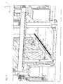
- FIGS. 1 to 5show a rapid prototyping system 100 according to a first embodiment of the invention, which is equipped for selectively solidifying the building material layers with a printing device.
- the building box 200, the mixing apparatus 300, the coater 400, and the coater cleaning apparatus 600can be easily used in a laser sintering facility, with minor modifications if necessary.
- the system 100can be converted, for example, to a laser-sintering system by replacing the printhead 500 with a radiation source or a laser.
- a shaped bodye.g. a mold, made directly from previously generated CAD data by forming superimposed layers of building material and by selectively solidifying portions of the respective building material layer prior to forming the next layer.
- the molding or the building material layersare built on a building platform 210 of a Baubox 200.
- the building materialhas particulate matter.
- sandcan be used as particulate material, in particular a sand commonly used in foundry technology.
- the application of the respective building material layertakes place with a coater 400, which can be moved horizontally over the build platform 210.
- the coater 400is fed via a mixing device 300 with building material.
- a printing device 500is used with a horizontally movable print head 510, with which a suitable binder on the layer to be solidified / printed can be given, for which the print head 510 is driven meandering across the layer of building material.
- the particulate material"sticks" or selectively solidifies the particulate material.
- a binderfor example, a resin can be used, for example furan resin.
- a multi-component binderwherein a first Binder component (eg, the resin) is printed over the print head 510, and wherein a second binder component (eg, an activator or hardener) is mixed with the particulate material.
- the resin selectively printed by the printerreacts with the hardener present in the uppermost layer of sand, thereby curing the resin and thereby bonding / bonding individual grains of sand together.
- the hardening resinthe portion to be solidified of the uppermost layer is bonded to the portion to be solidified of the layer located immediately below the upper layer.
- the coater 400 and the printing device 500are accommodated in a housing 110 in which the building process described above takes place.
- the housing 110has windows 120a-120d for monitoring the process flow.
- the housing 110has a frontal Baubox retraction / extension opening 130 through which the Baubox 200 can be moved into the housing 110 in and out of this. How out FIG. 1 As can be seen, the Baubox retraction / extension opening 130 through a rear end wall / cladding wall 223
- the Baubox 200is closed when the Baubox 200 is fixed in the construction position. In other words, the building box 200 in the construction position forms part of the siding, so that no additional door or protection device is necessary.
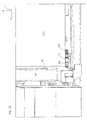
- the Baubox 200After completion of the molded body, the Baubox 200 from the housing 110 out in the in FIG. 2 driven by dashed lines indicated unpacking position. That is, the Baubox 200 is movable in the direction of arrow 201 between a construction position and an unpacking position (see FIG. 2 ). In the unpacking position, the finished molded body can be unpacked and uncovered, for example by lifting or moving up the building platform 210 and by blowing away or sucking off the loose, unconsolidated molding sand. The raising or lowering of the build platform 210 in the unpacking position can be automated or controlled manually via a push button 212 (see FIG FIG. 7 ).
- the moldingis removed, for example by hand and possibly subjected to a final cleaning, such as a brush.
- a final cleaningsuch as a brush.
- the Baubox 200is free and can be driven again in the housing 110 and in their construction position, so that the next job can be performed.
- the Baubox 200is thus constantly moved back and forth between the construction position and the Entpackungsposition, including the Baubox 200 is arranged on a rail system 140 (so-called. Simple shuttle operation). That is, in the FIGS. 1 to 5 shown plant 100 has exactly one Baubox 200.
- the Baubox 200is thus not designed as a swap body, but rather formed fixed to the plant; In particular, the Baubox 200 is self-propelled, for which they have a Baubox bathen, ie attached to the Baubox, drive 250 with its own drive motor 252 has (see FIG.
- the plant 100may also include a second building box 200 'along a second rail system 140 (or a common rail system) and through a second front building box retraction / extension opening in the housing 110 facing away from the first Baubox retraction / extension opening, along the arrow 201 between the common construction position and a second Entpackungsposition back and forth. Consequently, after the completion of a first molded article using the first building box 200, the first building box 200 can be moved to its associated first unpacking position to unpack the molded article.
- the second building box 200can be moved into the building position and fixed in order to produce a second molding using the second building box 200' (so-called double shuttle) -Business).
- double shuttle operationthe plant 100 can be operated quasi-continuously, whereas with the simple shuttle system only a batch operation is possible.
- the Baubox 200is system-resistant and self-propelled. Otherwise, the in figure 6 Plant 100 shown in the FIGS. 1 to 5 shown plant 100.
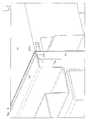
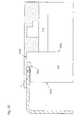
- FIGS. 3 to 5show the plant 100 without the housing 110.
- the building box 200is in the building position and the build platform 210 has moved up.
- the print head 510 of the printing device 500 and the coater 400are each in their parking position.
- coater 400 and printing device 500are arranged on opposite sides of the build platform 210; in particular, the print head carrier 520 and the coater carrier 430 are arranged parallel to one another and parallel to the longitudinal sides of the build platform 210.
- the two carriers 430 and 520can be moved in the y direction via the build platform 210, ie in the transverse direction of the build platform 210 and perpendicular to the travel direction of the Baubox 200.
- the print head 510in the x-direction, ie in the longitudinal direction of the build platform 210, along the print head carrier 520.
- the printhead carrier 520 and the coater carrier 430can also be arranged perpendicular to the longitudinal axis of the build platform 210, ie on the opposite short sides of the build platform 210, so that they are in the x-direction on the build platform 210th can be moved away.
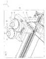
- the mixing device 300is attached to a vertical column 151 of the plant frame 150 above the supply container 410 and above the feed hopper 440 of the coater 400, with the discharge port 312 of the mixer 310 in the charging position of the coater 400 being disposed above the supply hopper 440 to move the hopper 440 Supply container 410 via the feed hopper 440 with freshly prepared building material.
- the system 100also has a central control device, not shown, with which the process flow and the individual components such as mixing device 300, coater 400, printing device 500, coater cleaning station 600 and printhead cleaning station 700 can be controlled.
- control deviceshould also encompass a "rule", i. the control device can also be a control device.
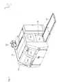
- FIGS. 7 to 15the Baubox 200 (which is alternatively referred to as a building container 200) and provided for the Baubox 200 rail system 140 (in particular FIGS. 7 to 9 ), the Bauboxfix istssystem for aligning and fixing the Baubox 200 to the plant frame 150 ( FIGS. 10 to 12 ) as well as the construction field cover ( FIGS. 13 to 15 ) described in detail.
- the Bauboxfour side walls 221, 223, 224 and 226, which each extend in the vertical direction.
- the front side wall / end wall 221serves as a cladding wall and forms with a vertical front wall 220 of the Baubox a space for receiving the traction drive 250 and the linear actuator 260 (see FIG. 8 ).
- the rear side wall / end wall 223serves as a lining wall and forms with a vertical rear wall (not shown) of the construction box a second space for receiving a further lifting drive (not shown).
- the two side walls 224 and 226together with the front wall 220 and the rear wall after one top and bottom open container or limiting frame, which is rectangular in longitudinal section, ie the boundary frame has two short side walls and two long side walls.
- the building box 200has a first construction field plate / cover plate 232 and a second construction field plate / cover plate 230 extending horizontally between and perpendicular to the two long side walls 224 and 226, respectively, and covering the first and second spaces upward.
- the two panels 230, 232form one of the parts of the construction panel cover (see eg FIG. 13 ).
- the building box 200has a building platform 210 which forms a vertically adjustable container floor, for which purpose the building platform underside is supported on a building platform support (not shown), e.g. a support arm is supported, which is movable via a lifting drive in the vertical direction.
- the building platform topforms the work surface on which the object to be manufactured is built.
- a plurality of side guide rollers 240(four according to this embodiment) which cooperate with the rail system 140 to center / align the building box 200 in / along the y-direction, ie in Baubox transverse direction to allow.
- the guide rollers 240may, for example, roll on the inner sides of the rails 141, 142.
- the two skids 242are on the inner sides of the rails 141, 142 mounted rollers 144, which in FIG. 7 are shown in dashed lines.
- a gear 254is attached to the Bauboxunterseite, the part of in FIG. 8 shown Baubox discoverede traction drive 250 is and in the in FIG. 9 shown rack 143 of the rail system 140 engages. In a rotational movement of the gear 254, the Baubox 200 is therefore moved in the x-direction over the rollers 144 away.
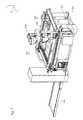
- FIG. 8shows the Baubox 200 without the front end wall 221.
- the Baubox 200has a Baubox integrated Baubox drive 250 and a built-in Baubox 200 build platform lifting drive 260 on.
- the Baubox travel drive 250 and the build platform lift drive 260are mounted on the front face of the Baubox 200 (between the front end wall 221 and the front wall 221 parallel thereto).
- Thishas the advantage that the drag chain / tow cable 270 for the electrical connections (see. Figures 2 and 3 ) can be made shorter and easier to guide, since the front end face 220 faces in the unpacking position of the Baubox the housing 110 of the system.
- the two drives 250, 260can also be positioned at a different location, for example, in each case at the rear end side.
- the two drives 250, 260also on the front and the rear Be distributed on the front side.
- FIG. 8shown on the front end of a drive 250 and a linear actuator 260 is provided, wherein at the rear end side of an additional lifting drive (not shown) is provided, which is synchronized with the linear actuator 260.
- an additional travel drivecan also be provided on the rear end side.
- the Baubox traction drive 250With the Baubox traction drive 250, the Baubox 220 between the construction position and the unpacking position in the above-mentioned simple shuttle operation back and forth (in the x-axis direction, ie in the longitudinal direction of the Baubox). Due to the own drive 250, a separate device for extending and retracting the Baubox 200 in or out of the housing 110 can be omitted. In addition, the height can be reduced.
- the Baubox traction drive 250has a traction drive motor 252, which is part of the Baubox 200.
- the motor 252drives the already described above gear 254, which engages in the rack 143.
- the travel drive 250is connected to the central control device (also via the drag chain 270), so that the procedure of the Baubox 200 can be automated.
- the build platform lift drive 260has a lift drive motor 262 that is part of the build box 200.
- the build platform lift drive 260further includes a rotatably mounted screw shaft 264 and a spindle nut (not shown) which is movable up and down by rotation of the spindle 264 along the spindle.
- the spindle nutis with the carrier (not shown) connected, which supports the building platform 200 on its underside.
- a recess in the front wall 221is provided, through which the support arm engages in order to support the building platform 210 from below.
- the building platform 210can be lowered or raised.
- Such a spindle drive mechanismis eg in the DE 20 2006 010 327 U1 to which reference is made insofar as the spindle drive comprising the motor, the spindle, the spindle nut and the support arm is concerned.
- the Baubox 200is different than the one in the DE 20 2006 010 327 U1 described building container not designed as a swap body, but rather an integral part of the system.
- the sealing of the recess in the front wall 221, through which the carrier engages,can be effected, for example, with a metal sheet which functions in the manner of a roller blind and bears against the inside of the front wall 221 when the building platform 210 is lowered, around the support arm recess to cover / seal.
- Such a sealis eg in the DE 100 47 615 described (see there the Figures 2 and 3 ), to which reference is made.
- the power supply of the motor 262as the power supply of the motor 252 via the drag chain 270 (see. Figures 2 and 3 ).
- the build platform lifting drive 260is also connected to the central control device (also via the drag chain 270), so that the lowering of the build platform 210 during the construction process can be controlled by the control device.
- the lifting of the build platform 210 in the unpacked position of the Baubox 200can either also be controlled by the central controller or manually controlled by pressing the push button 212.
- the integrated into the Baubox 200 linear actuator 260can thus both during the construction process and when unpacking the finished Shaped bodies are used so that a separate motor for Unpacking can be saved. Furthermore, the construction platform after completion of a construction job before moving out of the housing in the unpacking position must not be lowered to the bottom dead center, as is the case with systems in which the linear actuator is mounted on the system frame, but can immediately after completion of the molding be moved with the baubox districten drive 250 in the unpacking, in which the build platform 210 is raised via the baubox mediume linear actuator 260. Thus, by the arrangement of linear actuator 260 and drive 250 on the Baubox 200 also a time savings can be achieved.
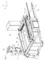
- FIG. 9shows the Baubox 200 on the provided for the Baubox 200 rail system 140.
- the rail system 140has a first rail 141 and a second rail 142, which are arranged parallel to each other. Furthermore, the rail system 140 has a rack 143, which is arranged parallel to and close to the second rail 142.
- the teeth of the rack 143face the first rail 141.
- the gear box 254 attached to the box bottomengages the teeth of the rack 143 to roll off the rack 143 when the gear is driven by the motor 252.
- the two guide rollers 240roll off, which are mounted on the side of the second side wall 226 (see. Fig. 12 ).
- the two guide rollers 240can also roll on the inside of the second rail 142.
- the two guide rollers 240which are mounted on the side of the first side wall 226, roll on the inside of the first rail 141.
- the construction boxis thus centered by the guide rollers along / in the y direction.
- rollers(not shown) are attached to the mutually facing inner surfaces of the rails, over which the Baubox 200 can roll with the skids 242.
- the Baubox 200is exactly in the predetermined construction position, for which the Baubox 200 should be centered and fixed in all axial directions.
- the construction boxis sufficiently fixed by its own weight.
- the building box 200has at one of the two side walls (at the second side wall 226 according to this embodiment) a stopper plate 226a, an alignment recess 226b, and a sensor target 226c.
- the stopper plate 226ais disposed rearward in the longitudinal direction, ie, near the rear end wall 223, and the recess 226b is located at the front (near the front end wall 221). However, the position of the stopper plate 226a and the position of the recess 226b may also be reversed. In the z direction, the stopper plate 226a and the recess 226b are disposed in the lower portion of the side wall.
- the alignment recess 226bis cone-shaped.
- the sensor target 226cis arranged substantially centrally in the longitudinal direction.
- first pressing member / alignment member 152cooperating with the alignment recess 226b
- second pressing member / fixing member 154cooperating with the stopper blade 226a
- a sensor 156attached to the sensor target object 226c cooperates.
- the first pressing element 152 and the second pressing element 154are each movable / movable in the y-direction.
- the movement of the two pressing elements 152 and 154is controlled via the central control device.
- the first pressing member 152has a mandrel shaped according to the shape of the tapered recess 226b. In particular, the end portion of the first pressing member 152 is cone-shaped.
- the second pressing element 154has a bolt with a flat end section.
- the sensor 156detects whether the sensor target 226c is in a predetermined position. When the sensor target 226c is in the predetermined position, the sensor outputs a "box-in-position signal" to the central controller. The central control device then causes an extension of the two pressing elements 152, 154, ie a movement in the y-direction to the Baubox 200 out. Thereby, the first pressing member 152 with the cone in the recess 226c (see FIG. 12 ) and the second pressing member 154 is pressed with the flat end portion against the stop plate 226a, whereby a centering and fixing of the Baubox 200 takes place in / along the x-direction and on the plant frame. Then the construction process can begin.
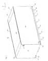
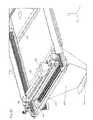
- FIG. 13the Baubox 200 is fixed in its construction position. How out FIG. 13 It can be seen that the construction platform 210 or the construction field surrounding Baufeldabdeckung or Baufeldumrahmung on the one hand by the two attached to the Baubox 200 horizontal cover plates 230 and 232 and the other by two system side horizontal boundary plates 158 and 159 (see also Figures 24 and 25 ), which are attached to the plant frame 150.
- the first side wall 224has a step 224d on its upper side or on its upper edge surface which extends in the horizontal direction between the outer side 224a and the inner side 224b of the first side wall 224.
- the step 224dadjoins the inner side 224b and is arranged substantially in the same horizontal plane as the two building box side construction field plates 230, 232.
- a horizontal edge surface 224cis formed, which is lowered relative to the step 224d and forms a sealing surface.
- the horizontal edge surface 224cadjoins the outside 224a.
- the amount or the Height by which the sealing surface 224c is lowered relative to the horizontal surface of the step 224d and the two baubox dirten Baufeldplatten 230, 232is slightly greater than the thickness of the frame-side Baufeldplatte / delimiting plate 158, so that sufficient vertical play between the bottom of the frame-side construction field plate 158th and the sealing surface 224c is provided, so that the Baubox 200 can be safely moved to the construction position.
- the gap s formed between the sealing surface 224c and the frame-side construction field plate 158may, for example, have a gap height of 3 to 20 mm, for example a gap height of 3 to 10 mm.
- the sealing surface 224chas such a width that on the one hand there is sufficient horizontal play between the frame-side construction field plate 158 and the step 224d to move the construction box 200 into and out of the construction position, and on the other hand, sufficient build material run length is provided ,
- the build material run lengthis the length by which the seal face 224d is surmounted by the frame side build field plate 158 (see FIG Fig. 15 ), ie the building material run length corresponds to the length of the gap formed between the sealing surface 224c and the frame-side construction field plate 158.
- the building material run lengthis chosen so that the building material in the gap s dead (see FIG. 15 ).
- a single layer thicknessmay be between 0.1 and 1 mm thick, eg 0.2 mm thick.
- the vertical height of the stepcan be eg 1.5 to 5mm, eg about 2 to 4mm.
- the horizontal distance between step and boundary plate For example, 158may be 2 to 6mm, for example, about 3 to 4mm.
- the vertical distance between horizontal surface 224c and limiting plate 158may be, for example, 1 to 4mm, eg, about 2 to 3mm.
- the overlap length between horizontal surface 224c and boundary plate 158may be, for example, 10 to 30mm, eg, about 15 to 20mm.
- the width of the stepcan be eg 1.5 to 4mm, eg 2mm.
- the width of the horizontal surface 224cmay be, for example, 30 to 40 mm, eg 35mm. Of course, these dimensions are only exemplary and can vary greatly depending on the application.
- the second side wall 226is also provided with a step to form a pouring cone seal between the building box 200 and the frame-side building field plate 159.
- the Baubox 200can thus be moved over the integrated drive 250 along the x-direction in the construction position and fixed with the above Bauboxfix istssystem in the construction position, which can be started immediately after the fixation of the Baubox 200 with the construction job. Further steps, such as a lifting of the Baubox 200 are not required. Furthermore, the height of the plant can be kept low because the construction field height is substantially equal to the Baubox dawn.
- the mixing device 300is not limited to the use of the "printing equipment” described herein, but rather may be applied in other rapid prototyping equipment / processes, such as e.g. during laser sintering.
- the mixing device or mixing unit 300has a mixer 310, with which a homogeneous mixture of building materials can be produced.
- the mixeris arranged above the coater 400 and integrated in the system 100.
- the mixer 310is here designed as a cylindrical container defining a mixing chamber in which a mixing element is arranged, which is drivable via a mixing drive, which is connected to the central control device.
- the mixing chamberhas a funnel-shaped dispensing opening 312 which is in the loading position of the coater 400 (see Fig. 16 ) is arranged above the coater 400, so that the coater 400, the freshly prepared in the mixer 310 building material through the discharge opening 312 can be fed.
- the mixeris attached to a vertical pillar 151 of the plant frame 150.
- the discharge opening 312 of the mixer 310is closed by an adjustable valve, which is controlled by the central control device.
- the mixing unit 300further comprises a first metering container 320, which is arranged above the mixer 310, in which fresh molding sand is received, and a second metering container 330, which is arranged above the mixer 310, in which recycled molding sand is received.
- the first dosing tank 320 and the second dosing tank 330each stand on three load cells 322, 332, which detect the weight of the associated dosing tank 320, 330 and which in each case to the central control device are connected.
- the two dosing 320, 330are each via a pipe, with the mixer 310 in connection.
- an adjustable valveeg a flap or valve
- the first dosing tank 320 and the second dosing tank 330can each be filled with molding sand via a suction line, which is not shown, which can be fastened to the connecting piece 326, 336, for which purpose they each have a device 324, 334 for generating negative pressure.
- the mixing unit 300may include a third metering vessel (not shown) disposed above the mixer 310, in which a powdery aggregate, e.g. is fed via a rotary valve in the mixer 310, which is in communication with the central control device.
- a powdery aggregatee.g. is fed via a rotary valve in the mixer 310, which is in communication with the central control device.
- the mixer 310by means of a metering pump 344 through a liquid line 342 a liquid (here activator / hardener) metered from a first liquid container 340 and fed controlled.
- a liquidhere activator / hardener
- the building materialcan be freshly prepared directly in the system during the construction operation and made available to the coater in a short way, in particular immediately after the preparation.
- the individual componentsare conveyed in pure form to the mixing unit arranged above the coater in the feed station of the plant (solids / powder, for example via a suction line, liquids, for example via pumps), where the mixture of building materials is prepared and after its Completion is fed into the coater, by opening the valve (eg flap or slider), which controls the discharge port 312.
- the valveeg flap or slider
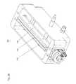
- FIGS. 18 to 21show a horizontally movable coater 400 for applying the building material layer on the construction field.
- the coater 400has an elongate metering shaft 410 funnel-shaped in cross-section.
- the metering shaft 410has on its underside a longitudinal slot 412 for discharging the building material during the movement of the metering shaft 410 over the building field.
- the metering chute 410On its upper side, the metering chute 410 has an upper feed opening 414, through which building material can be supplied to the metering chute 410.
- the coater 400further has a supply container 420 which moves along with the metering shaft and is arranged above the metering shaft 410 and has a lower delivery opening 422 which dips into the feed opening 414 of the metering shaft 410 in order to supply the metering shaft 410 with building material during the construction process.
- a supply container 420which moves along with the metering shaft and is arranged above the metering shaft 410 and has a lower delivery opening 422 which dips into the feed opening 414 of the metering shaft 410 in order to supply the metering shaft 410 with building material during the construction process.
- the metering well 410 and the receiver 420are mounted on a coater carrier 430, with the reservoir 420 pivotally connected to the coater carrier 430 so that it can be pivoted away from the carrier 430 and the metering well 410.
- the coater carrier 430is as in FIG. 18 shown secured to the support 430 by means of a locking device 450 having a gripping arm 452 mounted in the in FIG. 18 shown Locking state engages in a provided on the storage container 420 engagement opening 454.
- the accessibility of the metering duct and the storage container for cleaning and / or repair thereofis improved.
- the systemcan enter and, e.g. the template container 420 is pivoted away from the metering well 410 and the carrier 430 to clean / repair individual locations / parts of the coater 400, such as e.g.
- the coater 400can be made large due to the pivotable design of the storage container 420, while still easily cleaned by a single person and / or can be repaired, since no lifting device or the like is needed to lift the storage container upwards and away from the dosing shaft.
- a distributor screw 426is arranged, which is pivotable together with the feed container 420 and which distributes the building material along the feed container longitudinal direction.
- a supply funnel 440is screwed through which building material is disposed above the coater 400 Mixing device 300 can be introduced into the storage container 420 into it.
- the longitudinal slot 412 of the metering shaft 410is partially covered by a particle material deflection plate 416, which is arranged at a distance above the longitudinal slot 412 parallel to this.
- the printing apparatus 500has a printhead 510 suspended from the carrier 520, which is provided with a plurality of printhead nozzles 514 for the controlled discharge of resin onto the building material layer to be solidified.
- the printhead 510has a plurality of printing modules 512 arranged in series in the printhead-carrier longitudinal direction (x-direction) and each having a plurality of printhead nozzles 514 arranged in printhead-carrier transverse direction (y-direction). Direction) are arranged one behind the other in series.
- the printing modules 514are arranged in two printing module rows, the modules 512 of the one row are arranged offset to the modules 512 of the other row.
- the printhead 510is mounted on a carriage 530, which is movably guided on the carrier underside of the printhead carrier 520 along the printhead-carrier longitudinal axis, so that the printhead in the x-direction can be moved and overall meandering over the construction field can be moved.
- the printhead 510is disposed below the printhead carrier 520, at least partially under the carrier 520 (see FIG. 23 ).
- the center of gravity of the printhead 510is below the printhead carrier 520, preferably also below the carriage 530.
- alignment errors of the printhead nozzles 514are minimized and therefore the print quality can be increased.
- a good parallelism and a defined distance of the printhead undersideare ensured to the top of the layer to be printed on the construction field.
- the number of printhead nozzles 514 or printhead modules and consequently the system throughputcan be significantly increased, without this affecting the quality of the component to be produced.
- the distance of the printhead bottom from the top of the layer to be printedcan be minimized.
- tilting torques acting on the guide carriage 530 and its guide on the print head carrier 520can be reduced, so that the ease of movement of the guide carriage 530 of the print head is improved, in particular with small incremental movements, which in turn contributes to an improvement in print quality.
- the systemcan be built narrower, since the parking position of the Printhead carriage 520, in which the printhead carriage 520 is parked between two consecutive printing operations, can be moved closer to the building field as compared to a conventional printhead device in which the printhead is suspended laterally adjacent to the printhead carriage and therefore it protrudes in the horizontal direction.
- the FIGS. 24 to 26 2shows a coater cleaning apparatus 600 for cleaning the metering well 410 of the above-described coater 400.
- the coater cleaning apparatus 600has an elongated brush 610 that is accommodated below the metering well 410 of the coater 400 in a building material receptacle 620.
- the length of the brush 610is at least as long as the length of the metering well 410.
- the brush 610is rotatably supported and is rotatably driven by a wiper drive 612 connected to the central controller.
- the central control devicecontrols the entire cleaning process of the coater 400, ie the method of the coater 400 toward the cleaning device 600, the rotational movement of the brush 610 as soon as the coater 400 is in the cleaning position and the return movement of the coater 400 into its parking position after the coater 400 Cleaning.
- the control devicecan initiate a cleaning of the coater 400, for example after a predetermined number of coating runs or as a function of a sensor signal which indicates whether it is necessary to clean the metering shaft 410.
- a baffle 622arranged such that building material, which is stripped by means of the brush 610 from the metering chute 410, is deflected by the deflecting plate 622 to the underside of the building material collecting container 620.
- the construction material catcher 620enters a storage hopper for excess building material, and the hopper enters a reservoir exit pan 630.
- the reservoir exit well 630communicates via a slot with an output port 632 provided in an outer wall of the plant housing 110 and through which the build material accumulated in the reservoir is removable, eg, aspiratable, during the building process.
- the resin to be printed by the printhead 510is highly viscous and, under some circumstances, may adhere to the nozzle openings or to the printhead underside. Likewise, swirled particulate matter may adhere to the printhead bottom. To remove such buildup / deposits and to clean the printhead bottom, printhead cleaning device 700 is provided.
- the cleaning device 700 shownhas a container with a trough-shaped depression 710 in which a cleaning bath / solvent (not shown) is accommodated.
- a supply pipe and a discharge pipeare formed on a lower tank portion.
- the cleaning device 700further comprises two elongated strip-shaped wiper lips 720, which are made of a flexible rubber material.
- the wiper lips 720extend along the tub longitudinal direction and have a length which is only slightly smaller than that of the tub.
- the two wiper lips 720are held by an elongate carrier element 730.
- the carrier element 730has a rectangular cross-section holding part, in the top two longitudinal grooves are formed, in which the wiper lips 720 are inserted.
- the wiper lips 720are laterally fixed by two screws, which are screwed into a side surface of the holding part.
- the holding partis attached to a shaft via three screws.
- the shaftis rotatably supported on the two longitudinally opposite wall sides of the tub. The rotational movement of the shaft is controlled by the central control device.
- the two wiper lips 720can thus between the in FIG. 2 shown printhead cleaning position and the in FIG. 3 shown wiper lip regeneration positions are pivoted back and forth.
- the rotational movement of the shaftis controlled such that the two wiper lips basically in the in FIG. 29 are shown, in which the wiper lips 720 dive into the cleaning bath, so that adhering to the wiper lips binder and particulate material can be dissolved in the cleaning bath or at least passes from the wiper lips in the bath, whereby the wiper lips 720 are independently cleaned / regenerated.
- the fill level of the cleaning bath in the recess 710is preferably selected such that at least the wiper lip part protruding from the holding part is completely immersed in the cleaning bath.
- control deviceAfter a predetermined number of printing passes has been completed, the control device causes a rotational movement of the shaft through 180 °, so that the two wiper lips 720 from the in FIG. 29 shown regeneration position in the in FIG. 28 shown printhead cleaning position.
- control devicecontrols the printhead 510 such that it moves toward the cleaning device 700 and (possibly several times) over it, whereby its underside is cleaned.
- the wiper lips 720are again moved to their regeneration position and the cleaned printhead 510 moved to its parking position.
- a plurality of nozzles 750may be arranged, with which the two wiper lips 720 can be hosed in their regeneration position.
- the nozzles 710may be provided additionally or alternatively to the cleaning bath.
- FIGS. 30a to 30eFurther embodiments of the printhead cleaning device are in the FIGS. 30a to 30e shown with the print head cleaning position is shown in dashed lines.
Landscapes
- Chemical & Material Sciences (AREA)
- Engineering & Computer Science (AREA)
- Materials Engineering (AREA)
- Physics & Mathematics (AREA)
- Manufacturing & Machinery (AREA)
- Optics & Photonics (AREA)
- Mechanical Engineering (AREA)
- Finishing Walls (AREA)
- Producing Shaped Articles From Materials (AREA)
Description
Translated fromGermanDie vorliegende Erfindung betrifft eine Anlage zum schichtweisen Aufbau eines Formkörpers durch Ausbilden übereinander liegender Schichten von Baumaterial auf einem Baufeld und durch selektives Verfestigen eines Teilbereichs der jeweiligen Baumaterial-Schicht vor dem Ausbilden der nächstfolgenden Schicht gemäß dem Oberbegriff des Anspruchs 1.The present invention relates to a system for the layered construction of a molded article by forming superimposed layers of building material on a construction field and by selectively solidifying a portion of the respective building material layer before forming the next following layer according to the preamble of
Eine derartige Anlage (z.B. eine sog. Rapid-Prototyping-Anlage) kann z.B. einen horizontal verfahrbaren Beschichter aufweisen, mit dem gleichmäßige Schichten aus dem zu verfestigendem Baumaterial, z.B. ein Partikelmaterial oder ein Gemisch enthaltend Partikelmaterial, in mehrfacher Wiederholung auf das Baufeld aufgebracht werden können, wozu der Beschichter horizontal über das Baufeld hin verfahrbar ist.Such a system (e.g., a so-called rapid prototyping system) may e.g. have a horizontally movable coater, with the uniform layers of the building material to be solidified, e.g. a particulate material or a mixture containing particulate material can be applied to the construction field in multiple repetition, for which purpose the coater can be moved horizontally over the construction field.
Die jeweilige Schicht wird nach ihrer Aufbringung in einem selektiven Teilbereich verfestigt, so dass der Formkörper aus den selektiv verfestigten Teilbereichen aufgebaut wird. Zur selektiven Verfestigung des Teilbereichs der jeweiligen Baumaterial-Schicht kann z.B. eine Druckvorrichtung mit einem entlang eines Druckkopf-Trägers in einer ersten Horizontalrichtung verfahrbaren Druckkopf eingesetzt werden, wobei der Druckkopf-Träger selbst in einer zweiten Horizontalrichtung verfahrbar ist, so dass der Druckkopf über das gesamte Baufeld hin verfahrbar ist. Der Druckkopf weist eine Mehrzahl von Düsen auf, durch die ein geeignetes fließfähiges, insbesondere flüssiges Behandlungsmittel (wie beispielsweise ein Bindemittel, z.B. ein Harz), das zu der selektiven Verfestigung des Teilbereichs beiträgt, gesteuert auf die selektiv zu verfestigende Schicht aufgegeben/aufgedruckt werden kann. Eine Alternative zu einem derartigen Druckverfahren stellt das sog. Lasersintern dar, bei dem die selektive Verfestigung des Teilbereichs der jeweiligen Schicht durch gezielte Einfuhr von Wärme mittels eines Lasers erfolgt.The respective layer is solidified after its application in a selective subregion, so that the shaped body is built up from the selectively solidified subregions. For example, a printing device with a print head which can be moved in a first horizontal direction along a print head carrier can be used for selective solidification of the subregion of the respective building material layer, wherein the print head carrier itself can be moved in a second horizontal direction, so that the print head extends over the whole Construction field is movable. The printhead has a plurality of nozzles through which a suitable flowable, especially liquid, treatment agent (such as a binder, eg, a resin), which contributes to the selective consolidation of the portion controlled on the selectively to be consolidated layer can be abandoned / printed. An alternative to such a printing process is the so-called laser sintering, in which the selective solidification of the subregion of the respective layer takes place by targeted introduction of heat by means of a laser.
Das Baufeld, auf welches die einzelnen Baumaterial-Schichten aus dem Beschichter in mehrfacher Wiederholung aufgebracht werden, kann z.B. von einer höhenverstellbaren Bauplattform gebildet sein, welche in dem Innenraum einer nach oben offenen Baubox aufgenommen ist. Zu Beginn eines Bauprozesses zum Aufbauen eines Formkörpers ist die Bauplattform nach oben gefahren. Auf die nach oben gefahrene Bauplattform wird mittels des Beschichters eine erste Baumaterial-Schicht aufgebracht und anschließend z.B. vermittels einer Druckvorrichtung in einem vorbestimmten Teilbereich selektiv verfestigt. Nachdem die erste Baumaterial-Schicht selektiv verfestigt wurde, wird die Bauplattform um eine Schichtdicke abgesenkt, woraufhin mittels des Beschichters eine zweite Baumaterial-Schicht auf die Bauplattform bzw. auf die zuvor selektiv verfestigte erste Baumaterial-Schicht aufgebracht wird. Anschließend wird die zweite Baumaterial-Schicht selektiv verfestigt, und die Bauplattform wird erneut um eine Schichtdicke abgesenkt. Diese Schritte werden solange wiederholt, bis der Formkörper aus den selektiv verfestigten Schichten hergestellt ist. Der Baubereich, in dem der Formkörper hergestellt/aufgebaut wird, wird somit von dem Innenraum der Baubox sowie der Bauplattform begrenzt. Zum Entpacken des fertiggestellten Formkörpers kann die Bauplattform einfach wieder nach oben gefahren werden, so dass der Formkörper aus dem losen, nicht verfestigten Baumaterial entnommen werden kann.The construction field, to which the individual building material layers are applied from the coater in multiple repetition, can be formed, for example, by a height-adjustable construction platform, which is accommodated in the interior of an upwardly open construction box. At the beginning of a building process for building a molded body, the construction platform has gone up. A first building material layer is applied to the building platform moved upwards by means of the coater and then selectively solidified, for example, by means of a printing device in a predetermined partial area. After the first building material layer has been selectively solidified, the construction platform is lowered by one layer thickness, whereupon a second layer of building material is applied to the building platform or to the previously selectively solidified first building material layer by means of the coater. Subsequently, the second building material layer is selectively solidified, and the building platform is lowered again by a layer thickness. These steps are repeated until the molding is made from the selectively solidified layers. The construction area in which the molding is manufactured / built, is thus limited by the interior of the Baubox and the build platform. To unpack the finished molded article, the construction platform can simply be moved upwards again, so that the molded article can be removed from the loose, non-solidified construction material.
Da die Bauplattform während des Bauprozesses schrittweise um eine Schichtdicke abgesenkt wird, bevor eine neue Schicht auf die zuvor verfestigte Schicht aufgebracht wird, kann der vertikale Abstand von dem Beschichter und von der Druckvorrichtung (oder alternativ von einem Laser) gegenüber dem Baufeld bzw, der obersten Baumaterial-Schicht konstant gehalten werden, was das Aufbringen und das Verfestigen der Schichten erleichtert.Since the build platform is progressively lowered one layer thickness during the build process before a new coat is applied to the previously solidified coat, the vertical distance from the coater and from the printing device (or alternatively from a laser) may be opposite the build field or top Building material layer are kept constant, which facilitates the application and solidification of the layers.
Als eine Alternative hierzu sind im Stand der Technik Verfahren/Vorrichtungen bekannt, bei denen die Bauplattform nicht bewegt wird, d.h. während des Bauprozesses stationär ist, und der Beschichter sowie die Druckvorrichtung schrittweise angehoben werden, um den Vertikalabstand zwischen Beschichter/Druckvorrichtung und Baufeld konstant zu halten.As an alternative to this, in the prior art methods / devices are known in which the build platform is not moved, i. during the building process, and the coater and the printing device are gradually raised to keep the vertical distance between coater / printer and construction field constant.
Die Baubox, in der die Bauplattform aufgenommen ist, ist zum Aufbauen des Formkörpers in dem Rahmen/Baurahmen der Anlage angeordnet und insbesondere an diesem fixiert (=Baubox-Bauposition). In der Baubox-Bauposition wird das Baufeld bzw. der Baubereich von einer sog. horizontalen Baubereichsabdeckung oder horizontalen Baubereichsbegrenzung in der Art eines Rahmens zumindest teilweise, bevorzugt vollständig umfangsseitig umgeben. Z.B. wird hierzu im Stand der Technik eine anlagenfeste, an dem Baurahmen der Anlage befestigte horizontale rahmenförmige Baubereichsbegrenzung verwendet. Die horizontale Baubereichsbegrenzung ist in einer Höhe angeordnet, die deutlich größer ist als die Höhe der Baubox, so dass die Baubox zu Beginn des Bauprozesses problemlos in die Baubox-Bauposition und unter die horizontale rahmenförmige Baubereichsbegrenzung gefahren werden kann. Anschließend wird die gesamte Baubox um einen Betrag angehoben, der der Differenz zwischen der Höhe der horizontalen Baubereichsabgrenzung und der Höhe der Baubox entspricht, so dass der obere Rand der Baubox auf Höhe der horizontalen Baubereichsbegrenzung ist und von dieser umfangsseitig umgeben wird. Sodann wird mittels des Beschichters auf die nach oben gefahrene Bauplattform die erste Baumaterial-Schicht aufgebracht. Überschüssiges Baumaterial wird während des Bauprozesses auf der Baubereichsabdeckung bzw. Baubereichsbegrenzung angesammelt. Ein zwischen Baubox bzw. Bauboxwand und Baubereichsbegrenzung ausgebildeter Raum in Form eines Horizontalspalts wird idR durch Vorsehen einer Dichtung abgedichtet.The Baubox, in which the construction platform is included, is arranged for building the molding in the frame / construction frame of the system and in particular fixed to this (= Baubox construction position). In the Baubox construction position, the construction field or the construction area is surrounded by a so-called horizontal construction area coverage or horizontal building area boundary in the manner of a frame at least partially, preferably completely peripherally. For example, a plant-fixed, attached to the building frame of the system horizontal frame-shaped construction area limit is used for this purpose in the prior art. The horizontal building area boundary is located at a height that is significantly greater than the height of the construction box, so that the construction box can easily be moved to the construction box construction position and under the horizontal frame-shaped construction area boundary at the beginning of the construction process. Subsequently, the entire Baubox becomes one Amount corresponding to the difference between the height of the horizontal building demarcation and the height of the Baubox, so that the upper edge of the Baubox is at the level of the horizontal building area boundary and is surrounded by this peripherally. Then, by means of the coater, the first building material layer is applied to the construction platform driven upwards. Excess building material is accumulated during the construction process on the building area cover or construction area boundary. A trained between Bauboxwand Bauboxwand and Baubereichsbegrenzung space in the form of a horizontal gap is usually sealed by providing a seal.
Das Dokument
Alternativ ist es im Stand der Technik bekannt, die Seitenwand bzw. Begrenzungswand für das herzustellende Bauteil gemeinsam mit dem herzustellenden Bauteil während dessen Aufbau aufzubauen.Alternatively, it is known in the art to construct the side wall or boundary wall for the component to be produced together with the component to be produced during its construction.
Es ist eine Aufgabe der Erfindung, eine Anlage zum schichtweisen Aufbau eines Formkörpers bereitzustellen, bei der der von der Baubox (bzw. über der Bauplattform) gebildete Baubereich einfach und effizient abdichtbar ist. Mit anderen Worten soll auf einfache und effiziente Weise eine Dichtung zwischen der Baubox und einer Baubereichsbegrenzung, welche den Baubereich zumindest teilweise umgibt, ausgebildet werden.It is an object of the invention to provide a system for the layered construction of a shaped body in which the construction area formed by the building box (or via the building platform) can be simply and efficiently sealed. In other words, a seal is to be formed in a simple and efficient manner between the construction box and a construction area boundary which at least partially surrounds the construction area.
Hierzu stellt die Erfindung eine Anlage zum schichtweisen Aufbau eines Formkörpers nach Anspruch 1 bereit, und mehr spezifisch aufweisend eine Baubox und eine erste anlagenfeste Begrenzungsplatte. Die Baubox hat eine Vorderwand, eine Rückwand und zwei Seitenwände, welche zusammen einen nach oben offenen Bauboxinnenraum begrenzen. Zum Beispiel ist die Baubox in der Draufsicht rechteckig ausgebildet, z.B. mit langen Seitenwänden, einer kurzen Vorderwand und einer kurzen Rückwand. In dem von den vertikalen Bauboxwänden gebildeten Bauboxinnenraum ist eine höhenverstellbare Bauplattform aufgenommen. Der Bauboxinnenraum definiert über der Bauplattform einen Baubereich, in dem der Formkörper aufgebaut werden kann, wenn sich die Baubox in ihrer Bauposition befindet, d.h. wenn die Baubox zum Aufbauen des Formkörpers in dem Baurahmen der Anlage angeordnet und insbesondere an diesem fixiert ist.For this purpose, the invention provides a system for the layered construction of a shaped body according to
Die erste anlagenfeste Begrenzungsplatte hat eine horizontale Oberseite, von welcher in der Baubox-Bauposition entlang einer ersten Bauboxwand, z.B. entlang einer der beiden Seitenwände, eine den Baubereich teilweise umfangsseitig umgebende Baubereichsbegrenzung gebildet wird. Die horizontale Oberseite der Begrenzungsplatte erstreckt sich dabei insbesondere senkrecht zu der vertikalen ersten Bauboxwand und zwar entlang des oberen Randbereichs der ersten Bauboxwand. Z.B. ist die Begrenzungsplatte an dem Baurahmen der Anlage befestigt. Z.B. hat die horizontale Oberseite der ersten Begrenzungsplatte eine langgestreckte Streifenform.The first fixed boundary plate has a horizontal top from which in the construction box construction position along a first building box wall, e.g. along one of the two side walls, a building area partially surrounding the construction area boundary is formed. The horizontal upper side of the boundary plate extends in this case in particular perpendicular to the vertical first building box wall, specifically along the upper edge region of the first building box wall. For example, the boundary plate is attached to the building frame of the system. For example, The horizontal top surface of the first boundary plate has an elongated strip shape.
Die erste Bauboxwand hat im Bereich ihres oberen Randes eine horizontale Randfläche. Z.B. hat die horizontale Randfläche eine langgestreckte Streifenform. Die horizontale Randfläche kann z.B. von dem oberen Stirnrand der ersten Bauboxwand ausgebildet sein, d.h. einstückig mit der Bauboxwand, oder von einer an der Bauboxwand in dem Bereich des oberen Rands, z.B. an der Außenseite der Bauboxwand, angebrachten horizontalen Randflächenplatte ausgebildet sein. Wenn die Baubox in der Baubox-Bauposition angeordnet ist, wird die horizontale Randfläche von der ersten Begrenzungsplatte derart zumindest teilweise überlappt/übergriffen, dass zwischen der Unterseite der Begrenzungsplatte und der horizontalen Randfläche ein Spalt gebildet ist. Die horizontale Randfläche wird von der ersten Begrenzungsplatte lediglich teilweise überlappt/übergriffen. Der Spalt ist derart dimensioniert, dass außerhalb des Baubereichs eingebrachtes, überschüssiges Baumaterial sich in dem Spalt totläuft. Mit anderen Worten wird von dem Spalt eine Schüttkegeldichtung bzw. Labyrinthdichtung ausgebildet. D.h., von dem Baumaterial, welches in den Spalt eindringt und Partikelmaterial aufweist, wird an dem inneren Spaltende, welches einen Baumaterial-Eintrittsbereich formt (= der dem Baufeld zugewandte Bereich des Spalts), ein Schüttkegel ausgebildet, der in Richtung zu dem äußeren Spaltende hin abfällt und vor dem äußeren Spaltende endet/zum Stehen kommt. Die Breite der Randfläche kann größer sein als die Dicke der Bauboxwand.The first Bauboxwand has in the region of its upper edge a horizontal edge surface. For example, the horizontal edge surface has an elongated strip shape. The horizontal edge surface may be formed, for example, from the upper end edge of the first Bauboxwand, ie formed integrally with the Bauboxwand, or from a on the Bauboxwand in the region of the upper edge, for example on the outside of the Bauboxwand, mounted horizontal edge surface plate. If the Baubox is placed in the Baubox construction position, the horizontal boundary surface of the first boundary plate at least partially overlapped / overlapped, that between the underside of the boundary plate and the horizontal edge surface, a gap is formed. The horizontal edge surface is only partially overlapped / overlapped by the first boundary plate. The gap is dimensioned such that excess building material introduced outside the construction area runs dead in the gap. In other words, a bulk material seal or labyrinth seal is formed by the gap. That is, of the building material which penetrates into the gap and has particulate matter, at the inner gap end which forms a building material entrance area (= the area of the nip facing the work field), a pour cone is formed facing toward the outer column end falls off and ends before the outer end of the column / comes to a stop. The width of the edge surface may be greater than the thickness of Bauboxwand.
Somit kann auf einfache aber dennoch effiziente Weise eine Abdichtung zwischen der Baubereichsbegrenzung, welche erfindungsgemäß zumindest teilweise durch die erste anlagenfeste Begrenzungsplatte gebildet wird, und der Baubox bereitgestellt werden.Thus, in a simple yet efficient way, a seal between the construction area boundary, which according to the invention is at least partially formed by the first plant-fixed boundary plate, and the Baubox be provided.
Zudem kann die Aufbauhöhe (= Höhe des Baufeldes bzw. der obersten Schicht) und folglich die Höhe der Anlage bzw. des Baugehäuses mit der vorliegenden Erfindung reduziert werden, da beispielsweise die horizontale Oberseite der ersten anlagenfesten Begrenzungsplatte in einer Höhe montiert sein kann, die lediglich um denjenigen Betrag größer ist als die Höhe der Baubox, der sich zusammensetzt aus der Spalthöhe und der Dicke der Begrenzungsplatte und ggf. aus der Höhe eines Schienensystems, auf dem die Baubox steht und entlang dem die Baubox in die Baubox-Bauposition und aus dieser herausgefahren werden kann. Die vorliegende Erfindung ist somit insbesondere für eine verfahrbar ausgebildete Baubox geeignet, die z.B. zwischen der Baubox-Bauposition und einer zusätzlichen Position verfahrbar ist, wie z.B. einer Entpackungsposition, in der die Baubox außerhalb des Baurahmens angeordnet ist und in der der hergestellte Formkörper ausgepackt werden kann. Die Baubox kann z.B. einfach mit ihrer horizontalen Randfläche unter die Begrenzungsplatte horizontal in die Bauposition hinein gefahren werden, wobei nach einer Fixierung der Baubox an dem Baurahmen der Anlage unmittelbar mit dem Bauprozess begonnen werden kann, da sich Dichtung zwischen horizontaler Randfläche und Begrenzungsplatte automatisch, d.h. von selbst, ausgebildet wird, sobald Partikelmaterial aus dem Beschichter auf das Baufeld ausgegeben wird. Am Ende eines Bauprozesses kann die Baubox unmittelbar nach dem Lösen der Fixierung einfach aus der Bauposition herausgefahren werden. Somit kann mit der vorliegenden Erfindung auch diejenige Zeit eingespart werden, die im Stand der Technik für ein Anheben und Absenken der Baubox vor und nach dem Bauprozess aufgebracht werden muss.In addition, the construction height (= height of the construction field or the uppermost layer) and consequently the height of the plant or of the building housing can be reduced with the present invention, since for example the horizontal top of the first fixed boundary plate can be mounted at a height that only by that amount is greater than the height of the Baubox, which is composed of the gap height and the thickness of the boundary plate and possibly from the height of a rail system on which the Baubox is and along the Baubox in the Baubox construction position and can be moved out of this. The present invention is therefore particularly suitable for a moveable trained Baubox, for example, between the Baubox construction position and an additional position is movable, such as an unpacking position in which the Baubox is located outside the building frame and in which the molded body produced can be unpacked , The Baubox can eg be driven horizontally with its horizontal edge surface under the boundary plate in the construction position inside, which can be started directly to the construction process after fixing the Baubox on the frame of the system, since seal between the horizontal edge surface and boundary plate automatically, ie by itself, is formed as soon as particle material is discharged from the coater on the construction field. At the end of a construction process, the construction box can be moved out of the construction position immediately after loosening the fixation. Thus, the time saved by the prior art for raising and lowering the building box before and after the building process can also be saved with the present invention.
Daher ist die Baubox gemäß einer vorteilhaften Ausführungsform der Erfindung verfahrbar ausgebildet.Therefore, the Baubox is designed to be movable according to an advantageous embodiment of the invention.
Hierzu kann die Baubox z.B. einen eigenen Baubox-Fahrantrieb zum Verfahren der Baubox zwischen der Baubox-Bauposition und einer zusätzlichen Position aufweisen. Der Baubox-Fahrantrieb kann zum Beispiel ein an der Baubox befestigtes Zahnrad aufweisen, das von einem in die Baubox integrierten Fahrmotor antreibbar ist. Das Zahnrad, welches z.B. an der Bauboxunterseite angebracht ist und z.B. eine vertikale oder horizontale Radebene aufweisen kann, kann z.B. mit einer Zahnstange eines Schienensystems zusammenwirken, entlang dem die Baubox verfahrbar ist. Das Zahnrad greift in die Zahnstange ein, die bei horizontaler Radebene des Zahnrades seitlich einer Fahrschiene an dieser angeordnet sein kann, und rollt auf der zahnstange ab, wenn es von dem Fahrmotor angetrieben wird, so dass die Baubox entlang der Zahnstange verfahrbar ist. Die Baubox kann dabei z.B. über eine Schleppkette elektrisch mit der Anlage in Verbindung stehen, z.B. mit einer zentralen Steuereinrichtung und/oder einer zentralen Stromversorgung der Anlage. Gemäß einer alternativen Ausführungsform kann die Baubox aber auch manuell verfahrbar sein, z.B. mit Rollen oder Rädern versehen sein oder auf einer Rollenbahn der Anlage verschiebbar sein.For this purpose, the Baubox example, have their own Baubox drive to process the Baubox between the Baubox construction position and an additional position. The Baubox traction drive, for example, have a fixed to the Baubox gear that is drivable by a built-in Baubox traction motor. The gear, which is attached to the Bauboxunterseite example and, for example, a vertical or horizontal gear plane may, for example, cooperate with a rack of a rail system along which the Baubox is movable. The gear engages the rack, which can be arranged at the horizontal gear plane of the gear side of a running rail at this, and rolls on the rack from when it is driven by the traction motor, so that the Baubox is moved along the rack. The Baubox can be electrically connected to the system, for example via a drag chain, eg with a central control device and / or a central power supply of the system. According to an alternative embodiment, the Baubox but also be manually movable, for example, be provided with wheels or wheels or be displaceable on a roller conveyor of the system.
Ferner kann die Baubox seitliche Führungsrollen aufweisen, welche z.B. an der Unterseite der Baubox befestigt sind, und welche sich auf entsprechenden Führungsschienen eines Schienensystems seitlich abrollen. Dadurch kann eine Zentrierung der Baubox in/entlang einer Horizontalrichtung senkrecht zur Fahrtrichtung erfolgen, so dass die Baubox gezielt in die Bauposition und mit der Randfläche unter die Begrenzungsplatte gefahren werden kann. Diese Ausführungsform eignet sich sowohl für eine selbst fahrende Baubox als auch für eine manuell verfahrbare oder extern angetriebene Baubox. Ferner kann die Baubox an ihrer Unterseite ein Paar von Gleit- oder Rollkufen aufweisen, mit denen die Baubox auf einem Paar von Schienen des Schienensystems gleitend oder rollend aufliegt. Die Kufen können z.B. auf Rollen des Schienensystems abrollen oder z.B. auf entsprechenden Gleitflächen des Schienensystems gleiten.Furthermore, the Baubox may have lateral guide rollers, which are for example attached to the bottom of the Baubox, and which roll laterally on corresponding guide rails of a rail system. As a result, the Baubox can be centered in / along a horizontal direction perpendicular to the direction of travel, so that the Baubox can be driven selectively into the construction position and with the edge surface under the boundary plate. This embodiment is suitable both for a self-propelled Baubox as well as for a manually movable or externally powered Baubox. Further, the building box may have on its underside a pair of skids or skids with which the building box slidingly rides on a pair of rails of the rail system. For example, the skids can roll on rollers of the rail system or, for example, slide on corresponding sliding surfaces of the rail system.
Zur Zentrierung und Fixierung der Baubox in der Bauposition kann die Anlage ein Bauboxfixierungssystem zum Ausrichten der Baubox in/entlang der Baubox-Fahrtrichtung und zum Fixieren der Baubox an dem Baurahmen aufweisen. Das Bauboxfixierungssystem weist ein anlagenseitiges horizontal verstellbares Ausrichtelement mit einem sich verjüngenden Endabschnitt (z.B. einen Ausrichtdorn) sowie eine bauboxseitige sich verjüngende Vertiefung (z.B. eine konusförmige Vertiefung) auf, welche an einer der Bauboxwände ausgebildet ist und in welche der sich verjüngende Endabschnitt das anlagenseitigen Ausrichtelements in der Baubox-Bauposition eingreift. Zudem kann das Bauboxfixierungssystem ein anlagenseitiges Fixierelement (z.B. einen Bolzen) mit einem flach ausgebildeten Endabschnitt aufweisen, der gegen ein an der Bauboxwand angebrachtes Anschlagplättchen verstellbar drückbar ist. Als Gegenlager kann beispielsweise ein Schienensystem auf der gegenüberliegenden Bauboxseite dienen. Ferner kann das Bauboxfixierungssystem einen Sensor aufweisen zum Ermitteln der Position der Baubox, insbesondere, ob die Baubox sich in der Bauposition befindet. Hierzu kann an der Baubox ein Sensor-Zielobjekt angebracht sein. Ferner kann das Bauboxfixierungssystem ein Steuersystem aufweisen, welches einen Antrieb des Ausrichtelements und des Fixierelements derart ansteuert, dass das Ausrichtelement in die Ausrichtvertiefung einfährt und das Fixierelement gegen das Anschlagplättchen gedrückt wird, wenn der Sensor detektiert, dass die Baubox in der Bauposition ist.For centering and fixing the construction box in the construction position, the plant may have a Bauboxfixierungssystem for aligning the Baubox in / along the Baubox direction of travel and for fixing the Baubox to the building frame. The Bauboxfixierungssystem has a plant side horizontally adjustable alignment element with a tapered end portion (eg an alignment mandrel) and a Bauboxseitige tapered depression (eg a cone-shaped depression), which is formed on one of the Bauboxwände and into which the tapered end portion of the plant-side alignment element in engages the Baubox construction position. In addition, the Bauboxfixierungssystem may have a plant-side fixing element (such as a bolt) having a flat end portion which is adjustably pressed against a mounted on the Bauboxwand stop plate. As an abutment, for example, serve a rail system on the opposite Bauboxseite. Furthermore, the Bauboxfixierungssystem may have a sensor for determining the position of the Baubox, in particular, whether the Baubox is in the construction position. For this purpose, a sensor target object can be attached to the construction box. Furthermore, the Bauboxfixierungssystem may have a control system which drives a drive of the alignment and the fixing such that the alignment element enters the alignment and the fixing is pressed against the stop plate when the sensor detects that the Baubox is in the construction position.
Gemäß einer Ausführungsform der Erfindung kann eine zweite anlagenfeste Begrenzungsplatte vorgesehen sein, die mit einer horizontalen Randfläche einer zweiten Bauboxwand eine Schüttkegel-Labyrinthdichtung der oben beschriebenen Art ausbildet.According to one embodiment of the invention, a second fixed boundary plate can be provided, which with a horizontal edge surface of a second Bauboxwand a Flood cone labyrinth seal of the type described above trains.
Die jeweilige mit der Randfläche versehene Bauboxwand, d.h. die erste und/oder zweite Bauboxwand, kann im Bereich ihres oberen Randes ferner eine Stufe aufweisen, welche in der Baubox-Bauposition in horizontaler Richtung zwischen der Randfläche und dem Baubereich angeordnet ist und welche mit ihrer Oberseite gegenüber der Randfläche eine erhöhte Horizontalfläche ausbildet. Die Stufe kann im Querschnitt z.B. rechteckig oder quadratisch ausgebildet sein. Die von der Stufe gebildete erhöhte Horizontalfläche ist insbesondere in Höhe der Oberseite der Begrenzungsplatte angeordnet. Mit Hilfe dieser Stufe kann der Schüttkegel, der sich in dem jeweiligen Spalt ausbildet, genau/definiert eingestellt werden. Ferner haben die Erfinder erkannt, dass sich durch Anbringung/Ausbildung der Stufe eine sog. "Rissbildung" in dem Pulverbett während des Absenkens der Bauplattform verhindern oder zumindest stark reduzieren lässt. Eine solche "Abrisskante" kann im Stand der Technik auftreten, wenn die Bauplattform vor dem Aufbringen einer nächsten Schicht um eine Schichtdicke abgesenkt wird. Die Vermeidung einer solchen Abrisskante ist damit zu erklären, dass durch Vorsehen der Stufe eine Art Barriere oder Trennwand zwischen dem Ort der Abdichtung und der Bauboxinnenwand geschaffen wird.The respective fringed building box wall, i. the first and / or second Bauboxwand, may also have a step in the region of its upper edge, which is arranged in the Baubox construction position in the horizontal direction between the edge surface and the building area and which forms with its upper side opposite the edge surface an increased horizontal surface. The step may be in cross section e.g. be formed rectangular or square. The elevated horizontal surface formed by the step is arranged in particular at the level of the upper side of the boundary plate. With the help of this stage, the bulk cone, which forms in the respective gap, can be set exactly / defined. Furthermore, the inventors have recognized that by attaching / forming the step so-called "cracking" in the powder bed during the lowering of the construction platform can be prevented or at least greatly reduced. Such a "spoiler edge" can occur in the prior art if the build platform is lowered by one layer thickness before the application of a next layer. The avoidance of such a spoiler edge is to be explained by the fact that the provision of the stage creates a kind of barrier or partition wall between the location of the seal and the Bauboxinnenwand.
Bevorzugt liegt hierbei die Oberseite der Stufe in gleicher Höhe wie die obere freie Stirnfläche der Bauboxwand, so dass die freie Stirnfläche in gleicher Höhe wie die obere Fläche der Begrenzungsplatte liegt. Die horizontale Randfläche verläuft hierbei um einen Betrag tiefer als die Oberseite der Begrenzungsplatte, welcher der Summe der Dicke der Begrenzungsplatte und der Spalthöhe entspricht. Bei dieser Ausführungsform kann die Stufe in der freien oberen Stirnfläche der Bauboxwand ausgebildet sein. Es ist jedoch auch möglich, an der Außenseite der Bauboxwand eine abstehende Randplatte vorzusehen, von deren Oberseite die Randfläche ausgebildet wird, so dass von der freien oberen Stirnfläche der Bauboxwand die obere Fläche der Stufe gebildet wird.In this case, the upper side of the step preferably lies at the same height as the upper free end face of the building box wall, so that the free end face lies at the same height as the upper face of the boundary plate. The horizontal edge surface extends in this case by an amount lower than the top of the boundary plate, which is the sum of the thickness of the Boundary plate and the gap height corresponds. In this embodiment, the step may be formed in the free upper end face of the building box wall. However, it is also possible to provide on the outside of the Bauboxwand a protruding edge plate, from the upper side, the edge surface is formed so that the upper surface of the step is formed by the free upper end face of the Bauboxwand.
Bevorzugt sind genau zwei anlagenfeste Begrenzungsplatten vorgesehen, wobei die erste anlagenfeste Begrenzungsplatte und die zweite anlagenfeste Begrenzungsplatte beidseitig des Raums für die Baubox gegenüberliegend angeordnet sind. Jedoch ist es auch möglich, drei anlagenfeste Begrenzungsplatten vorzusehen. Bevorzugt wird mindestens eine Seite des Baufeldes offen gelassen, d.h. nicht mit einer Begrenzungsplatte versehen, so dass die Baubox seitlich in das Baufeld bzw. die Bauposition hineingefahren werden kann. Wenn die Baubox als stationärer Baubehälter ausgebildet ist, kann aber auch eine vierte anlagenfeste Begrenzungsplatte an der vierten Bauboxseite vorgesehen sein, so dass ein anlagenfester geschlossener Begrenzungsrahmen gebildet ist. Auch ist es möglich, lediglich eine anlagenfeste Begrenzungsplatte vorzusehen, z.B. zusammen mit drei Abdeckungsplatten der unten beschriebenen Art.Preferably exactly two fixed boundary plates are provided, wherein the first fixed boundary plate and the second fixed boundary plate are arranged on both sides of the space for the Baubox opposite. However, it is also possible to provide three fixed boundary plates. Preferably, at least one side of the construction field is left open, i. not provided with a boundary plate, so that the Baubox can be moved laterally in the construction field or the construction position. If the Baubox is designed as a stationary building container, but also a fourth fixed boundary plate can be provided on the fourth Bauboxseite, so that a fixed fixed boundary frame is formed. It is also possible to provide only a fixed boundary plate, e.g. together with three cover plates of the type described below.
Die beiden anlagenfesten Begrenzungsplatten erstrecken sich bevorzugt senkrecht zu der horizontalen Bewegungsrichtung des Beschichters, insbesondere des Beschichter-Trägers, und/oder der Druckvorrichtung, insbesondere des Druckkopf-Trägers. Mit anderen Worten verläuft die Längsachse des Beschichter-Trägers und/oder des Druckkopf-Trägers parallel zu den Begrenzungsplatten, so dass der Beschichter und die Druckkopfvorrichtung über die jeweilige anlagenseitige Begrenzungsplatte hinweg aus dem Baufeld heraus verfahrbar sind.The two fixed boundary plates extend preferably perpendicular to the horizontal direction of movement of the coater, in particular the coater carrier, and / or the printing device, in particular of the print head carrier. In other words, the longitudinal axis of the coater carrier and / or the printhead carrier is parallel to the boundary plates, so that the coater and the Printhead device over the respective plant-side boundary plate away from the building field are moved out.
Zum Beispiel kann die Baubox eine horizontale erste Abdeckungsplatte aufweisen, von welcher entlang einer (dritten) Bauboxwand, die benachbart zu der ersten Bauboxwand angeordnet ist, eine den Baubereich teilweise umfangsseitig umgebende Baubereichsbegrenzung gebildet wird. Das heißt, gemäß dieser Ausführungsform der Erfindung wird die Baubereichsbegrenzung bzw. Baubereichsabdeckung teilweise von der Baubox selbst ausgebildet. In der Baubox-Bauposition befindet sich die Abdeckungsplatte der Baubox dabei auf der gleichen Höhe wie die jeweilige anlagenseitige Begrenzungsplatte und grenzt an diese an. Zum Beispiel kann die Baubox eine horizontale zweite Abdeckungsplatte aufweisen, wobei die erste und die zweite Abdeckungsplatte einander gegenüberliegen. Wenn die Baubox mit ihrer Vorderwand voran in die Bauposition gefahren wird, ist die mindestens eine Abdeckungsplatte bevorzugt an der Rückseite der Baubox angeordnet.For example, the Baubox may have a horizontal first cover plate, of which along a (third) Bauboxwand, which is arranged adjacent to the first Bauboxwand, a building area partially surrounding the peripheral construction area boundary is formed. That is, according to this embodiment of the invention, the construction area boundary is partly formed by the building box itself. In the Baubox construction position, the cover plate of the Baubox is at the same height as the respective boundary plate on the installation side and adjoins it. For example, the building box may have a horizontal second cover plate with the first and second cover plates facing each other. When the construction box is moved forward with its front wall in the construction position, the at least one cover plate is preferably arranged at the back of the Baubox.
Die Erfindung wird im Folgenden anhand verschiedener Ausführungsformen mit Bezugnahme auf die Zeichnung näher erläutert. In der Zeichnung zeigen:
Figur 1Figur 2 eine zweite Perspektivansicht der erfindungsgemäßen Anlage ausFig. 1 ,Figur 3 eine dritte Perspektivansicht der Anlage ausFig. 1 , wobei das Gehäuse der Anlage weggelassen ist,Figur 4 eine vierte Perspektivansicht der Anlage ausFig. 1 , wobei das Gehäuse der Anlage weggelassen ist,Figur 5 eine fünfte Perspektivansicht der Anlage ausFig. 1 , wobei das Gehäuse der Anlage weggelassen ist,Figur 6 eine Perspektivansicht einer erfindungsgemäßen Anlage zum schichtweisen Aufbau eines Formköpers gemäß einer zweiten Ausführungsform der Erfindung,Figur 7 eine Perspektivansicht auf die vordere Stirnseite und eine benachbarte Seitenwand einer erfindungsgemäßenBaubox 200,Figur 8 die Ansicht ausFigur 7 , wobei die Verkleidungswand an der vorderen Stirnseite weggelassen ist, um den Fahrantrieb und den Hubantrieb der Baubox zu zeigen,Figur 9 eine Perspektivansicht auf die vordere Stirnseite der Baubox aus denFiguren 7 und8 , wobei die Baubox auf dem Schienensystem der Anlage angeordnet ist und wobei die Baubox in die Entpackungsposition gefahren ist,Figur 10 eine Perspektivansicht auf die vordere Stirnseite sowie eine weitere Seitenwand der Baubox, welche der inFigur 7 gezeigten Seitenwand abgewandt ist,Figur 11 eine Perspektivansicht des Anlagenrahmens und der daran angebrachten Komponenten des Bauboxfixierungssystems,Figur 12 eine Frontalansicht auf die vordere Stirnseite der Baubox, wobei sich die Baubox in der Bauposition befindet und an dem Anlagenrahmen fixiert ist,Figur 13Figur 14 eine Detailansicht der anlagenfesten Baufeldabdeckung, welche sich unter Ausbildung einer Labyrinthdichtung entlang einer Seitenwand der Baubox erstreckt,Figur 15 eine Detailansicht der zwischen der anlagenfesten Baufeldabdeckung und der Baubox ausgebildeten Labyrinthdichtung,- die
Figuren 16 und17 jeweils eine Perspektivansicht einer erfindungsgemäßenMischvorrichtung 300, Figur 18 eine Perspektivansicht auf die vordere Stirnseite eines erfindungsgemäßenBeschichters 400, wobei der Beschichter in seiner Betriebsposition ist, d.h. der Dosierschacht und der Vorlagebehälter des Beschichters sind jeweils an dem Beschichter-Träger befestigt,Figur 19 eine Perspektivansicht des Beschichters ausFig. 18 von vorne, wobei der Vorlagebehälter des Beschichters von dem Beschichter-Träger weg in eine Reinigungsposition geschwenkt ist, um z.B. die Verteilerschnecke des Vorlagebehälters zu reinigen,Figur 20 eine Perspektivansicht des Beschichters ausFig. 18 von hinten, wobei der Vorlagebehälter des Beschichters zusammen mit dem Zuführtrichter in eine Reinigungsposition geschwenkt ist, um z.B. die Zuführöffnung des Dosierschachts zu reinigen,Figur 21 eine Perspektivansicht des Beschichters ausFig. 18 , wobei der Beschichter in die Anlage eingebaut ist und in seiner Betriebsposition ist und wobei die vordere Stirnwand der einzelnen Beschichter-Komponenten weggelassen ist,Figur 22 eine Perspektivansicht einer erfindungsgemäßenDruckvorrichtung 500, welche einen Druckkopfträger und einen daran aufgehängten Druckkopf aufweist,Figur 23 eine Detailansicht des Druckkopfes ausFig. 22 und dessen Aufhängung an dem Druckkopfträger,Figur 23a eine schematische Unteransicht des Druckkopfkopfes, um die Anordnung der Druckkopfdüsen zu veranschaulichen,Figur 24 eine Perspektivansicht einer erfindungsgemäßenBeschichter-Reinigungsvorrichtung 600,Figur 25 eine Perspektivansicht der Beschichter-Reinigungsvorrichtung ausFigur 24 und des Beschichters,Figur 26 eine Perspektivansicht auf eine Seitenwand des Anlagengehäuses,Figur 27 eine Perspektivansicht von dem horizontal verfahrbaren Druckkopf in seiner Ruhe- bzw. Parkposition und von einer benachbart zu dem Druckkopf angeordneten erfindungsgemäßenDruckkopf-Reinigungsvorrichtung 700, welche gemäß der gezeigten Ausführungsform zwei seitlich nebeneinander angeordnete Wischlippen aufweist,Figur 28 eine Perspektivansicht der Druckkopf-Reinigungsvorrichtung ausFigur 27 , wobei sich die zwei Wischlippen in der Druckkopf-Reinigungsposition befinden,Figur 29 eine Perspektivansicht der Druckkopf-Reinigungsvorrichtung ausFigur 27 , wobei sich die zwei Wischlippen in der Wischlippen-Regenerationsposition befinden, und- die
Figuren 30a bis 30f verschiedene Ausführungsformen der erfindungsgemäßen Druckkopf-Reinigungsvorrichtung.
FIG. 1 1 is a perspective view of the front face of aplant 100 according to the invention for the layered construction of a molded article according to a first embodiment of the invention,FIG. 2 a second perspective view of the system according to the inventionFig. 1 .FIG. 3 a third perspective view of the plantFig. 1 with the housing of the plant omitted,FIG. 4 a fourth perspective view of the plantFig. 1 with the housing of the plant omitted,FIG. 5 a fifth perspective view of the plantFig. 1 with the housing of the plant omitted,FIG. 6 a perspective view of a system according to the invention for the layered construction of a molded article according to a second embodiment of the invention,FIG. 7 a perspective view of the front end side and an adjacent side wall of aBaubox 200 according to the invention,FIG. 8 the viewFIG. 7 in which the panel wall on the front end side is omitted in order to show the travel drive and the lifting drive of the construction box,FIG. 9 a perspective view of the front end of the Baubox from theFIGS. 7 and8th in which the construction box is arranged on the rail system of the installation and the construction box has moved into the unpacking position,FIG. 10 a perspective view of the front end face and another side wall of the Baubox, the inFIG. 7 facing away from the side wall shown,FIG. 11 a perspective view of the plant frame and attached components of the Bauboxfixierungssystems,FIG. 12 a frontal view of the front end of the Baubox, with the Baubox is in the construction position and is fixed to the plant frame,FIG. 13 a perspective view of the top of the Baubox or on the incorporated therein building platform, with the Baubox is in the construction position,FIG. 14 a detailed view of fixed installation Baufeldabdeckung which extends to form a labyrinth seal along a side wall of the Baubox,FIG. 15 a detailed view of the formed between the plant-fixed Baufeldabdeckung and the Baubox labyrinth seal,- the
Figures 16 and17 each a perspective view of amixing device 300 according to the invention, FIG. 18 a perspective view of the front face of acoater 400 according to the invention, wherein the coater is in its operating position, ie the metering shaft and the receiver of the coater are respectively attached to the coater carrier,FIG. 19 a perspective view of the coater offFig. 18 from the front, wherein the deposition container of the coater is pivoted away from the coater carrier in a cleaning position, for example, to clean the distributor screw of the storage container,FIG. 20 a perspective view of the coater offFig. 18 from behind, wherein the deposition container of the coater is pivoted together with the feed hopper in a cleaning position, for example, to clean the feed opening of the metering duct,FIG. 21 a perspective view of the coater offFig. 18 wherein the coater is built into the plant and in its operative position and with the front end wall of the individual coater components omitted,FIG. 22 a perspective view of aprinting device 500 according to the invention, which has a print head carrier and a printhead suspended therefrom,FIG. 23 a detailed view of the printheadFig. 22 and its suspension on the printhead carrier,FIG. 23a a schematic bottom view of the printhead head to illustrate the arrangement of the printhead nozzles,FIG. 24 a perspective view of acoater cleaning device 600 according to the invention,FIG. 25 a perspective view of the coater cleaning deviceFIG. 24 and the coater,FIG. 26 a perspective view of a side wall of the plant housing,FIG. 27 a perspective view of the horizontally movable printhead in its rest or parking position and arranged from one adjacent to the print headPrinthead cleaning device 700 according to the invention, which according to the embodiment shown has two wiper lips arranged laterally next to each other,FIG. 28 a perspective view of the printhead cleaning deviceFIG. 27 with the two wiper lips in the printhead cleaning position,FIG. 29 a perspective view of the printhead cleaning deviceFIG. 27 , wherein the two wiper lips are in the wiper lip regeneration position, and- the
FIGS. 30a to 30f Various embodiments of the printhead cleaning device according to the invention.
Die
Mit der Anlage 100 kann ein Formkörper, z.B. eine Gussform, unmittelbar aus zuvor generierten CAD-Daten hergestellt werden durch Ausbilden von übereinander liegenden Baumaterialschichten und durch selektives Verfestigen von Teilbereichen der jeweiligen Baumaterialschicht vor dem Ausbilden der nächsten Schicht.With the
Der Formkörper bzw. die Baumaterialschichten werden auf einer Bauplattform 210 einer Baubox 200 aufgebaut. Die Bauplattform 210 ist höhenverstellbar und kann vor dem Auftragen einer neuen Baumaterialschicht um eine Schichtdicke abgesenkt werden, so dass die Arbeitsebene (= oberste Baumaterialschicht) stets auf dem selbem Niveau ist.The molding or the building material layers are built on a
Das Baumaterial weist Partikelmaterial auf. Als Partikelmaterial kann zum Beispiel Sand eingesetzt werden, insbesondere ein Sand wie er üblicherweise in der Gießereitechnik verwendet wird. Das Aufbringen der jeweiligen Baumaterialschicht erfolgt mit einem Beschichter 400, der horizontal über die Bauplattform 210 hin verfahrbar ist. Der Beschichter 400 wird über eine Mischvorrichtung 300 mit Baumaterial gespeist.The building material has particulate matter. For example, sand can be used as particulate material, in particular a sand commonly used in foundry technology. The application of the respective building material layer takes place with a
Zur selektiven Verfestigung der jeweiligen Baumaterialschicht wird eine Druckvorrichtung 500 mit einem horizontal verfahrbaren Druckkopf 510 eingesetzt, mit dem ein geeignetes Bindemittel auf die zu verfestigende Schicht aufgegeben/aufgedruckt werden kann, wozu der Druckkopf 510 mäanderförmig über die Baumaterialschicht hinweg gefahren wird. Das Partikelmaterial "verklebt" bzw. verfestigt das Partikelmaterial selektiv. Als Bindemittel kann z.B. ein Harz eingesetzt werden, z.B. Furanharz. Zudem ist es möglich, ein Mehrkomponentenbindemittel zu verwenden, wobei eine erste Bindemittel-Komponente (z.B. das Harz) über den Druckkopf 510 aufgedruckt wird, und wobei eine zweite Bindemittel-Komponente (z.B. ein Aktivator oder Härter) mit dem Partikelmaterial vermengt ist. Das durch den Drucker selektiv aufgedruckte Harz reagiert mit dem in der obersten Sandschicht vorliegenden Härter, wodurch das Harz aushärtet und dadurch einzelne Sandkörner miteinander verbindet/verklebt. Zudem wird durch das aushärtende Harz der zu verfestigende Abschnitt der obersten Schicht mit dem zu verfestigenden Abschnitt der unmittelbar unter der oberen Schicht angeordneten Schicht verbunden.For selective solidification of the respective building material layer, a
Vereinfacht wiedergegeben kann ein Formteil demnach z.B. wie folgt ausgebildet werden:
- 1. Bereitstellen einer Baumaterialmischung, enthaltend Formsand und Härter, unter Verwendung des
Mischers 300, - 2. Chargenweiser/Schichtweiser Auftrag des Baumaterials auf die
Bauplattform 210 desBaubehälters 200 mit Hilfe desBeschichters 400, - 3. Eindosieren von Harz in die oberste Baumaterialschicht unter Verwendung der
Druckvorrichtung 500 - 4. und Wiederholen der Schritte 2 und 3, bis der Formkörper fertiggestellt ist.
- 1. providing a building material mixture containing foundry sand and hardener using the
mixer 300, - 2. Batchwise / layerwise application of the building material to the
build platform 210 of thebuilding container 200 with the aid of thecoater 400, - 3. dosing resin into the uppermost building material layer using the
printing device 500 - 4. and repeating steps 2 and 3 until the molding is completed.
Der Beschichter 400 und die Druckvorrichtung 500 sind in einem Gehäuse 110 untergebracht, in dem der oben beschriebene Bauprozess abläuft. Das Gehäuse 110 weist Fenster 120a-120d auf zum Beobachten des Prozessablaufs. Ferner weist das Gehäuse 110 eine stirnseitige Baubox-Einfahr/Ausfahr-Öffnung 130 auf, durch welche die Baubox 200 in das Gehäuse 110 hinein und aus diesem heraus gefahren werden kann. Wie aus
Nach Fertigstellung des Formköpers wird die Baubox 200 aus dem Gehäuse 110 heraus in die in
Die Baubox 200 wird somit ständig zwischen der Bauposition und der Entpackungsposition hin- und hergefahren, wozu die Baubox 200 auf einem Schienensystem 140 angeordnet ist (sog. einfacher Shuttle-Betrieb). D.h., die in den
Wie in
Die
Die Anlage 100 weist ferner eine nicht gezeigte zentrale Steuereinrichtung auf, mit der der Prozessablauf und die einzelnen Komponenten wie Mischvorrichtung 300, Beschichter 400, Druckvorrichtung 500, Beschichter-Reinigungsstation 600 und Druckkopf-Reinigungsstation 700 gesteuert werden können. Im Sinne dieser Anmeldung soll dabei von dem Begriff "Steuern" auch ein "Regeln" umfasst sein, d.h. die Steuereinrichtung kann auch eine Regelungseinrichtung sein.The
Im Folgenden werden unter Bezugnahme auf die
Wie in
Ferner weist die Baubox 200 eine erste Baufeldplatte/ Abdeckungsplatte 232 und eine zweite Baufeldplatte/ Abdeckungsplatte 230 auf, welche sich jeweils in horizontaler Richtung zwischen und senkrecht zu den beiden langen Seitenwänden 224 und 226 erstrecken und den ersten bzw. zweiten Zwischenraum nach oben abdecken. Wenn sich die Baubox 200 in der Bauposition befindet, bilden die beiden Platten 230, 232 einen der Teil der Baufeldabdeckung aus (siehe z.B.
Ferner weist die Baubox 200 eine Bauplattform 210 auf, die einen in vertikaler Richtung höhenverstellbaren Behälterboden ausbildet, wozu die Bauplattformunterseite auf einem Bauplattform-Träger (nicht gezeigt), z.B. einem Tragarm, abgestützt ist, der über einen Hubantrieb in vertikaler Richtung verfahrbar ist. Die Bauplattformoberseite bildet die Arbeitsfläche, auf der das herzustellende Objekt aufgebaut wird. Während des Bauprozesses, d.h. wenn sich die Baubox 200 in der Bauposition befindet, wird die Bewegung der Bauplattform durch die zentrale Steuereinrichtung gesteuert. Ferner kann die Position der Bauplattform 210 über einen an der vorderen Stirnwand 220 angebrachten Druckknopf 212 manuell eingestellt werden.Furthermore, the
An der Unterseite der Baubox 200 sind eine Mehrzahl von seitlichen Führungsrollen 240 angebracht (gemäß dieser Ausführungsform vier), welche mit dem Schienensystem 140 zusammenwirken, um eine zentrierung/Ausrichtung der Baubox 200 in/entlang der y-Richtung, d.h. in Baubox-Querrichtung, zu ermöglichen. Die Führungsrollen 240 können z.B. an den Innenseiten der Schienen 141, 142 abrollen. Ferner ist an der Unterseite bzw. unteren Stirnfläche/Randfläche der ersten Seitenwand 224 sowie an der Unterseite der zweiten Seitenwand 226 jeweils eine leistenförmige Gleitkufe 242 angebracht, wobei die beiden Gleitkufen 242 auf an den Innenseiten der Schienen 141, 142 angebrachten Rollen 144 stehen, welche in
Mit dem Baubox-Fahrantrieb 250 kann die Baubox 220 zwischen der Bauposition und der Entpackungsposition im oben erwähnten einfachen Shuttle-Betrieb hin- und hergefahren werden (in x-Achsenrichtung, d.h. in Längsrichtung der Baubox). Aufgrund des eigenen Fahrantriebs 250 kann eine separate Vorrichtung zum Ein- und Ausfahren der Baubox 200 in das bzw. aus dem Gehäuse 110 entfallen. Zudem kann die Aufbauhöhe reduziert werden. Der Baubox-Fahrantrieb 250 weist einen Fahrantriebs-Motor 252 auf, der Bestandteil der Baubox 200 ist. Die Stromversorgung des Fahrantrieb-Motors 252 erfolgt über eine Schleppkette 270 (vgl.
Der Bauplattform-Hubantrieb 260 weist einen Hubantrieb-Motor 262 auf, der Bestandteil der Baubox 200 ist. Der Bauplattform-Hubantrieb 260 weist ferner eine drehbar angeordnete Schraubspindel 264 und eine Spindelmutter (nicht gezeigt) auf, welche durch Drehung der Spindel 264 entlang der Spindel nach oben bzw. unten bewegbar ist. Die Spindelmutter ist dabei mit dem Träger (nicht gezeigt) verbunden, der die Bauplattform 200 an ihrer Unterseite abstützt. Hierzu ist eine Ausnehmung in der Vorderwand 221 vorgesehen, durch die der Tragarm greift, um die Bauplattform 210 von unten abzustützen. Somit kann durch eine Drehung der Spindel die Bauplattform 210 abgesenkt bzw. angehoben werden. Ein solcher Spindeltrieb-Mechanismus ist z.B. in der
Für den Bauprozess ist es wichtig, dass sich die Baubox 200 exakt in der vorbestimmten Bauposition befindet, wozu die Baubox 200 in allen Achsrichtungen zentriert und fixiert sein sollte. Die Zentrierung und Fixierung in y-Richtung erfolgt über das oben beschriebene Führungsrollensystem. In z-Richtung wird die Baubox durch ihr Eigengewicht ausreichend fixiert. Somit ist nach dem Einfahren der Baubox 200 in das Gehäuse 110 und in die Bauposition lediglich noch eine Zentrierung und Fixierung in x-Richtung erforderlich, welche durch das in den
Wie in
Wie in
Wenn die Baubox 220 in das Gehäuse 110 hinein gefahren ist, detektiert der Sensor 156, ob das Sensorzielobjekt 226c in einer vorbestimmten Position ist. Wenn das Sensorzielobjekt 226c in der vorbestimmten Position ist, gibt der Sensor ein "Baubox-in-Position-Signal" an die zentrale Steuereinrichtung aus. Die zentrale Steuereinrichtung veranlasst daraufhin ein Ausfahren der beiden Anpresselemente 152, 154, d.h. eine Bewegung in y-Richtung zu der Baubox 200 hin. Dadurch wird das erste Anpresselement 152 mit dem Konus in die Vertiefung 226c (siehe
Da die zentrierung in y-Richtung bereits durch die Führungsrollen 240 erfolgt, ist es ausreichend das Bauboxfixierungssystem einseitig auszubilden, d.h. es ist ausreichend, wenn nur eine der beiden Seitenwände mit der Vertiefung 226b und dem Anschlagplättchen 226a versehen ist.Since the centering in the y-direction already takes place through the
In
Wie aus den
In der gleichen Weise ist auch die zweite Seitenwand 226 mit einer Stufe versehen, um eine Schüttkegeldichtung zwischen der Baubox 200 und der rahmenseitigen Baufeldplatte 159 auszubilden.In the same way, the
Die Baubox 200 kann somit über den integrierten Fahrantrieb 250 entlang der x-Richtung in die Bauposition gefahren werden und mit dem obigen Bauboxfixierungssystem in der Bauposition fixiert werden, wobei unmittelbar nach der Fixierung der Baubox 200 mit dem Baujob begonnen werden kann. Weitere Schritte wie z.B. ein Anheben der Baubox 200 sind nicht erforderlich. Ferner kann die Anlagenhöhe gering gehalten werden, da die Baufeldhöhe im Wesentlichen der Bauboxhöhe entspricht.The
Im Folgenden wird unter Bezugnahme auf die
Es wird angemerkt, dass die Mischvorrichtung 300 ebenso wie die oben beschriebene Baubox 200 nicht auf die Verwendung der hierin beschriebenen "Druckanlange" beschränkt ist, sondern vielmehr auch in anderen Rapid-Prototyping-Anlagen/Verfahren angewendet werden kann wie z.B. beim Lasersintern.It should be noted that the
Die Mischvorrichtung oder Mischeinheit 300 weist einen Mischer 310 auf, mit dem eine homogene Baumaterial-Mischung erzeugt werden kann. Der Mischer ist oberhalb des Beschichters 400 angeordnet und in die Anlage 100 integriert. Der Mischer 310 ist hier als ein zylindrischer Behälter ausgebildet, der eine Mischkammer begrenzt, in der ein Rühr- bzw. Mischelement angeordnet ist, das über einen Mischantrieb antreibbar ist, der an die zentrale Steuereinrichtung angeschlossen ist. Die Mischkammer hat eine trichterförmige Ausgabeöffnung 312, die in der Beschickungsposition des Beschichters 400 (siehe
Die Mischeinheit 300 weist ferner einen oberhalb des Mischers 310 angeordneten ersten Dosierbehälter 320, in dem frischer Formsand aufgenommen ist, und einen oberhalb des Mischers 310 angeordneten zweiten Dosierbehälter 330 auf, in dem recycelter Formsand aufgenommen ist. Der erste Dosierbehälter 320 und der zweite Dosierbehälter 330 stehen jeweils auf drei Wiegezellen 322, 332, die das Gewicht des zugeordneten Dosierbehälters 320, 330 erfassen und die jeweils an die zentrale Steuereinrichtung angeschlossen sind. Die beiden Dosierbehälter 320, 330 stehen jeweils über eine Rohrleitung, mit dem Mischer 310 in Verbindung. In der jeweiligen Rohrleitung ist eine verstellbare Armatur (z.B. eine Klappe oder Ventil) vorgesehen, die von der zentralen Steuereinrichtung angesteuert wird. Der erste Dosierbehälter 320 und der zweite Dosierbehälter 330 können jeweils über eine nicht gezeigte Saugleitung, die an dem Anschlussstutzen 326, 336 befestigbar ist, mit Formsand befüllt werden, wozu sie jeweils eine Vorrichtung 324, 334 zum Erzeugen von Unterdruck aufweisen.The
Ferner kann die Mischeinheit 300 einen oberhalb des Mischers 310 angeordneten dritten Dosierbehälter (nicht gezeigt) aufweisen, in dem ein pulverförmiger Zuschlagstoff enthalten ist, der z.B. über eine Zellenradschleuse in den Mischer 310 eingespeist wird, die mit der zentralen Steuereinrichtung in Verbindung steht.Further, the
Ferner kann dem Mischer 310 mittels einer Dosierpumpe 344 durch eine Flüssigkeitsleitung 342 eine Flüssigkeit (hier Aktivator/Härter) aus einem ersten Flüssigkeitsbehälter 340 dosiert und gesteuert zugeführt werden.Further, the
Mit der oben beschriebenen Mischeinheit kann das Baumaterial während des Baubetriebs direkt in der Anlage frisch zubereitet und dem Beschichter insbesondere unmittelbar nach der Zubereitung auf kurzem Wege zur Verfügung gestellt werden. Die einzelnen Komponenten werden in Reinform zu der oberhalb des Beschichters in der Beschickungsstation der Anlage angeordneten Mischeinheit gefördert (Feststoffe/Pulver z.B. über eine Saugleitung, Flüssigkeiten z.B. über Pumpen), wo die Baumaterial-Mischung zubereitet wird und nach ihrer Fertigstellung in den Beschichter eingespeist wird, und zwar durch Öffnen der Armatur (z.B. Klappe oder Schieber), die die Ausgabeöffnung 312 beherrscht.With the mixing unit described above, the building material can be freshly prepared directly in the system during the construction operation and made available to the coater in a short way, in particular immediately after the preparation. The individual components are conveyed in pure form to the mixing unit arranged above the coater in the feed station of the plant (solids / powder, for example via a suction line, liquids, for example via pumps), where the mixture of building materials is prepared and after its Completion is fed into the coater, by opening the valve (eg flap or slider), which controls the
Die
Der Beschichter 400 weist weiter einen mit dem Dosierschacht mitfahrenden Vorlagebehälter 420 auf, der oberhalb des Dosierschachts 410 angeordnet ist und eine untere Ausgabeöffnung 422 aufweist, die in die Zuführöffnung 414 des Dosierschachtes 410 eintaucht, um den Dosierschacht 410 während des Bauprozesses mit Baumaterial zu versorgen.The
Der Dosierschacht 410 und der Vorlagebehälter 420 sind an einem Beschichter-Träger 430 montiert, wobei der Vorlagebehälter 420 schwenkbar mit dem Beschichter-Träger 430 verbunden ist, so dass er von dem Träger 430 und dem Dosierschacht 410 weggeschwenkt werden kann. Im Normalbetrieb ist der Beschichter-Träger 430 wie in
Aufgrund der verschwenkbaren Ausbildung des Vorratsbehälters 420 ist die Zugänglichkeit des Dosierschachts und des Vorratbehälters für eine Reinigung und/oder Reparatur derselben verbessert. Z.B. kann für eine Reinigung und/oder Reparatur des Beschichters 400 zunächst der Baubehälter 200 aus der Anlage 100 heraus gefahren werden, um in der Anlagenmitte Platz zu schaffen, woraufhin der Beschichter 400 in die Mitte der Anlage gefahren wird. Im Anschluss daran kann die Anlage betreten und z.B. der vorlagebehälter 420 von dem Dosierschacht 410 und dem Träger 430 weggeschwenkt werden, um einzelne Stellen/Teile des Beschichters 400 zu reinigen/reparieren, wie z.B. die Zuführöffnung 414 des Dosierschachts 410, die Ausgabeöffnung 422 des Vorlagebehälters 420 oder die Innenwände des Vorlagebehälters 420 und des Dosierschachts 410. Insbesondere kann der Beschichter 400 aufgrund der verschwenkbaren Ausbildung des Vorlagebehälter 420 groß dimensioniert werden, wobei er dennoch von einer einzelnen Person problemlos gereinigt und/oder repariert werden kann, da keine Hebevorrichtung oder dergleichen benötigt, um den Vorlagebehälter nach oben anzuheben und von dem Dosierschacht wegzubewegen.Due to the pivotable design of the
In dem Beschichter 400 ist eine Verteilerschnecke 426 angeordnet, die zusammen mit dem Vorlagebehälter 420 verschwenkbar ist und die das Baumaterial entlang der Vorlagebehälterlängsrichtung verteilt.In the
An der Oberseite des Vorlagebehälters 420 ist ein Zuführtrichter 440 angeschraubt, durch den Baumaterial aus der oberhalb des Beschichters 400 angeordneten Mischvorrichtung 300 in den Vorlagebehälter 420 hinein eingebracht werden kann.At the top of the
Der Längsschlitz 412 des Dosierschachts 410 ist teilweise von einer Partikelmaterial-Umlenkplatte 416 überdeckt, die im Abstand über dem Längsschlitz 412 parallel zu diesem angeordnet ist.The
Die in den
Ferner weist die Druckvorrichtung 500 einen an dem Träger 520 aufgehängten Druckkopf 510 auf, der mit einer Mehrzahl von Druckkopfdüsen 514 versehen ist zum gesteuerten Ausgeben von Harz auf die zu verfestigende Baumaterial-Schicht. Wie aus
Der Druckkopf 510 ist an einem Führungsschlitten 530 montiert, welcher an der Trägerunterseite des Druckkopf-Trägers 520 entlang der Druckkopf-Träger-Längsachse verfahrbar geführt ist, so dass der Druckkopf in x-Richtung verfahrbar ist und insgesamt mäanderförmig über das Baufeld verfahren werden kann. Der Druckkopf 510 ist unterhalb des Druckkopf-Trägers 520 angeordnet ist, wobei er den Träger 520 zumindest teilweise untergreift (siehe
Mit der oben beschriebenen Druckvorrichtung 500 kann ein von dem Druckkopf 510 erzeugtes Drehmoment um die Druckachse (= Druckkopf-Träger-Längsachse, x-Richtung) stark reduziert werden, wodurch einerseits eine Torsion des Druckkopf-Trägers 520 minimiert wird und somit die Stabilität und Schwingungsarmut des Druckkopfes 510 deutlich verbessert sind und wodurch andererseits Ausrichtfehler der Druckkopfdüsen 514 minimiert und daher die Druckqualität erhöht werden kann. Gleichzeitig werden eine gute Parallelität und ein definierter Abstand der Druckkopfunterseite zu der Oberseite der auf dem Baufeld zu bedruckenden Schicht sichergestellt. Dadurch können seinerseits die Anzahl der Druckkopfdüsen 514 bzw. Druckkopfmodule und folglich der Anlagendurchsatz deutlich erhöht werden, ohne dass hierunter die Qualität des herzustellenden Bauteils leidet. Weiter kann durch die Erhöhung der Stabilität und Schwingungsfestigkeit des Druckkopfes 510 der Abstand der Druckkopf-Unterseite zu der Oberseite der zu bedruckenden Schicht minimiert werden. Zudem können auf den Führungsschlitten 530 und dessen Führung an dem Druckkopf-Träger 520 einwirkende Kippmomente reduziert werden, so dass die Leichtgängigkeit des Führungsschlittens 530 des Druckkopfes insbesondere bei kleinen inkrementellen Bewegungen verbessert ist, was seinerseits zu einer Verbesserung der Druckqualität beiträgt. Des Weiteren kann die Anlage schmaler gebaut werden, da die Parkposition des Druckkopf-Trägers 520, in welcher der Druckkopf-Träger 520 zwischen zwei aufeinander folgenden Druckvorgängen geparkt ist, näher an das Baufeld heran gerückt werden kann, verglichen mit einer herkömmlichen Druckkopfvorrichtung, bei welcher der Druckkopf seitlich neben dem Druckkopf-Träger aufgehängt ist und daher von diesem in Horizontalrichtung wegragt.With the
Die
Das mit dem Druckkopf 510 aufzudruckende Harz ist stark viskos und kann unter gewissen Umständen an den Düsenöffnungen bzw. an der Druckkopfunterseite anhaften. Ebenso kann aufgewirbeltes Partikelmaterial an der Druckkopfunterseite anhaften. Um derartige Anhaftungen/Ablagerungen zu entfernen und die Druckkopf-Unterseite zu reinigen, ist die Druckkopf-Reinigungsvorrichtung 700 bereitgestellt.The resin to be printed by the
Die in den
Durch die gesteuerte Drehbewegung der Welle können die beiden Wischlippen 720 somit zwischen der in
Dabei wird die Drehbewegung der Welle derart gesteuert, dass sich die beiden Wischlippen grundsätzlich in der in
Nachdem eine vorbestimmte Anzahl von Druckfahrten absolviert wurde, veranlasst die Steuereinrichtung eine Drehbewegung der Welle um 180°, so dass die beiden Wischlippen 720 aus der in
Anschließend werden die Wischlippen 720 wieder in ihre Regenerationsposition bewegt und der gereinigte Druckkopf 510 in seine Parkposition gefahren.Subsequently, the
Wie in
Weitere Ausführungsformen der Druckkopf-Reinigungsvorrichtung sind in den
Claims (13)
- A device (100) for the layered construction of a shaped body by forming layers of construction material, comprising a particulate material, lying one upon another on a construction field, and by selectively solidifying a partial area of the respective construction material layer prior to forming the next layer, comprising:a construction box (200) having a front wall (220), a rear wall and two side walls (224, 226), which delimit a construction box interior space which is open to the upper side, in which a height-adjustable construction platform (210) is received and by which a construction area is defined above the construction platform (210), in which the shaped body can be constructed when the construction box (200) is in a construction position in which the construction box (200) is arranged in the frame (150) of the device (100) for constructing the shaped body, anda first device-fixed boundary plate (158) comprising a horizontal upper side by which along a first construction box wall (224) of the construction box walls a construction area boundary is formed, surrounding the construction area in part circumferentially, when the construction box is located in the construction box construction position,characterized in that the first construction box wall (224) comprises a horizontal edge surface (224c) in the area of its upper edge, which in the construction box construction position is at least partially overlapped by the first boundary plate (158) by forming a gap (s) located between the lower side of the boundary plate (158) and the horizontal edge surface (224c), the gap (s) being dimensioned such that excessive construction material brought-in outside the construction area stops running within the gap (s).
- The device (100) according to claim 1, further comprising
a second device-fixed boundary plate (159) comprising a horizontal upper side by which in the construction box construction position a construction area boundary is formed along a second construction box wall (226), surrounding the construction area in part circumferentially,
wherein the second construction box wall (226) comprises in the area of its upper edge a horizontal edge surface which in the construction box construction position is at least partially overlapped by the second boundary plate (159) by forming a gap (s) located between the lower side of the boundary plate (159) and the horizontal edge surface, the gap being dimensioned such that excessive construction material brought-in outside the construction area stops running within the gap (s). - The device (100) according to claim 1 or 2, wherein the respective construction box wall (224, 226) provided with the horizontal edge surface (224c) further comprises a step (224d) in the area of its upper edge, which is located in a horizontal direction between the horizontal edge surface (224c) and the construction area, and which forms an elevated horizontal surface relative to the horizontal edge surface (224c).
- The device (100) according to claim 3, wherein the elevated horizontal surface formed by the step is substantially located on the level of the upper side of the boundary plate (158, 159).
- The device (100) according to any of the preceding claims inasmuch as related to claim 2, wherein the first device-fixed boundary plate (158) and the second device-fixed boundary plate (159) are located opposite each other.
- The device (100) according to claim 5, further comprising a coating device (400) and/or a printing device (500), which is/are movable in a horizontal moving direction, the two device-fixed boundary plates (158, 159) extending perpendicularly to the respective moving direction.
- The device (100) according to any of claims 1 to 6, the construction box (200) comprising a horizontal first cover plate (232) by which along a third construction box wall located adjacent to the first construction box wall (224) a construction area boundary is formed surrounding the construction area in part circumferentially.
- The device (100) according to claim 7, wherein the construction box (200) comprises a horizontal second cover plate (230) by which along a fourth construction box wall (220) located adjacent to the first construction box wall (224) and being located opposite the third construction box wall a construction box boundary is formed surrounding the construction area in part circumferentially.
- The device (100) according to any of claims 1 to 8, wherein the construction box (200) is formed to be rectangular, having long side walls (224, 226), a short front wall (220) and a short rear wall, and wherein the respective construction box wall (224, 226) comprising the edge surface is one of the two side walls (224, 226).
- The device (100) according to any of claims 1 to 9, wherein the construction box (200) is movable from the construction box construction position into an additional position in which the construction box (200) is located outside the frame (150) of the device.
- The device (100) according to claim 10, wherein the construction box (200) is located on a rail system (140).
- The device (100) according to claim 10 or 11,
wherein the construction box (200) comprises its own construction box travel drive (250) for moving the construction box (200) between the construction box construction position and the additional position. - The device (100) according to any of claims 10 to 12, further comprising a construction box fixing system for aligning the construction box (200) in a construction box travel direction and for fixing the construction box (200) to the frame (150), when the construction box (200) is in its construction position, wherein the construction box fixing system comprises a device-sided alignment member (152) adjustable perpendicular to the moving direction of the construction box and having a tapered end portion, and a construction box-sided tapered alignment recess (226b) which is formed on one of the construction box walls (221, 223, 224, 226) and into which the tapered end portion of the device-sided alignment member (152) engages in the construction box construction position.
Applications Claiming Priority (2)
| Application Number | Priority Date | Filing Date | Title |
|---|---|---|---|
| DE102009056686ADE102009056686B4 (en) | 2009-12-02 | 2009-12-02 | Construction area limitation of a rapid prototyping facility |
| PCT/EP2010/068779WO2011067359A1 (en) | 2009-12-02 | 2010-12-02 | Delimitation of the construction area in a rapid-prototyping system |
Publications (2)
| Publication Number | Publication Date |
|---|---|
| EP2389286A1 EP2389286A1 (en) | 2011-11-30 |
| EP2389286B1true EP2389286B1 (en) | 2014-02-19 |
Family
ID=43856221
Family Applications (1)
| Application Number | Title | Priority Date | Filing Date |
|---|---|---|---|
| EP10805221.8AActiveEP2389286B1 (en) | 2009-12-02 | 2010-12-02 | Delimitation of the construction area in a rapid-prototyping system |
Country Status (3)
| Country | Link |
|---|---|
| EP (1) | EP2389286B1 (en) |
| DE (1) | DE102009056686B4 (en) |
| WO (1) | WO2011067359A1 (en) |
Families Citing this family (5)
| Publication number | Priority date | Publication date | Assignee | Title |
|---|---|---|---|---|
| DE102012106141B4 (en) | 2012-07-09 | 2018-04-26 | Exone Gmbh | METHOD AND DEVICE FOR UNPACKING A COMPONENT |
| RU2628627C1 (en) | 2013-08-27 | 2017-08-21 | Дзе Тимкен Компани | Separator, bearing assembly and method for manufacturing separator |
| JP6320123B2 (en)* | 2014-03-31 | 2018-05-09 | 三菱重工業株式会社 | Three-dimensional laminating apparatus and three-dimensional laminating method |
| DE102014112446A1 (en)* | 2014-08-29 | 2016-03-03 | Exone Gmbh | Method and device for unpacking a component |
| CN113751726A (en)* | 2021-06-15 | 2021-12-07 | 山东鑫聚龙动力科技集团有限公司 | A kind of engine narrow wall 3D printing molding method |
Family Cites Families (6)
| Publication number | Priority date | Publication date | Assignee | Title |
|---|---|---|---|---|
| JP4598219B2 (en)* | 2000-02-23 | 2010-12-15 | ツカサ工業株式会社 | Sliding gate valve for granular materials |
| DE10047615A1 (en)* | 2000-09-26 | 2002-04-25 | Generis Gmbh | Swap bodies |
| DE202004018586U1 (en)* | 2004-11-30 | 2005-03-17 | Concept Laser Gmbh | Device for creation of three-dimensional shape by hardening of layers with electromagnetic beams, comprising extremely solid lid |
| US7357629B2 (en)* | 2005-03-23 | 2008-04-15 | 3D Systems, Inc. | Apparatus and method for aligning a removable build chamber within a process chamber |
| DE102005030854B3 (en)* | 2005-07-01 | 2007-03-08 | Eos Gmbh Electro Optical Systems | Device for producing a three-dimensional object |
| DE202006010327U1 (en) | 2006-07-04 | 2007-11-15 | Prometal Rct Gmbh | Swap bodies |
- 2009
- 2009-12-02DEDE102009056686Apatent/DE102009056686B4/ennot_activeExpired - Fee Related
- 2010
- 2010-12-02EPEP10805221.8Apatent/EP2389286B1/enactiveActive
- 2010-12-02WOPCT/EP2010/068779patent/WO2011067359A1/enactiveApplication Filing
Also Published As
| Publication number | Publication date |
|---|---|
| EP2389286A1 (en) | 2011-11-30 |
| WO2011067359A1 (en) | 2011-06-09 |
| DE102009056686B4 (en) | 2012-01-12 |
| DE102009056686A1 (en) | 2011-06-09 |
Similar Documents
| Publication | Publication Date | Title |
|---|---|---|
| EP2507037B1 (en) | Installation for the layered construction of a shaped body, comprising a coating device cleaner | |
| EP2391499B1 (en) | Rapid prototyping system comprising a construction box | |
| EP2389285B1 (en) | Hopper for a rapid prototyping installation | |
| EP2507036B1 (en) | Rapid prototyping installation comprising a mixing unit | |
| DE102009056695B4 (en) | Print head cleaning device | |
| EP1872928B1 (en) | Method for building up three-dimensional parts | |
| EP2552675B1 (en) | Device and method for producing three-dimensional models | |
| EP3036087B1 (en) | Coating arrangement for a 3d printer | |
| EP3268210B1 (en) | 3d printer having a coater and coater cleaning device and method for cleaning a coater of a 3d printer | |
| WO2016030405A1 (en) | 3d printer, 3d printer arrangement and generative production method | |
| WO2012092912A1 (en) | Device and method for constructing a laminar body comprising at least one position-adjustable body defining the working area | |
| EP2389286B1 (en) | Delimitation of the construction area in a rapid-prototyping system | |
| DE102009056694B4 (en) | Printing device for a rapid prototyping system and rapid prototyping system | |
| EP3986701A1 (en) | Arrangement of 3d printing device |
Legal Events
| Date | Code | Title | Description |
|---|---|---|---|
| PUAI | Public reference made under article 153(3) epc to a published international application that has entered the european phase | Free format text:ORIGINAL CODE: 0009012 | |
| 17P | Request for examination filed | Effective date:20110824 | |
| AK | Designated contracting states | Kind code of ref document:A1 Designated state(s):AL AT BE BG CH CY CZ DE DK EE ES FI FR GB GR HR HU IE IS IT LI LT LU LV MC MK MT NL NO PL PT RO RS SE SI SK SM TR | |
| RAP1 | Party data changed (applicant data changed or rights of an application transferred) | Owner name:EXONE GMBH | |
| DAX | Request for extension of the european patent (deleted) | ||
| GRAP | Despatch of communication of intention to grant a patent | Free format text:ORIGINAL CODE: EPIDOSNIGR1 | |
| INTG | Intention to grant announced | Effective date:20130716 | |
| GRAS | Grant fee paid | Free format text:ORIGINAL CODE: EPIDOSNIGR3 | |
| GRAA | (expected) grant | Free format text:ORIGINAL CODE: 0009210 | |
| AK | Designated contracting states | Kind code of ref document:B1 Designated state(s):AL AT BE BG CH CY CZ DE DK EE ES FI FR GB GR HR HU IE IS IT LI LT LU LV MC MK MT NL NO PL PT RO RS SE SI SK SM TR | |
| REG | Reference to a national code | Ref country code:GB Ref legal event code:FG4D Free format text:NOT ENGLISH | |
| REG | Reference to a national code | Ref country code:CH Ref legal event code:EP | |
| REG | Reference to a national code | Ref country code:CH Ref legal event code:NV Representative=s name:PATENTANWAELTE SCHAAD, BALASS, MENZL AND PARTN, CH | |
| REG | Reference to a national code | Ref country code:AT Ref legal event code:REF Ref document number:652724 Country of ref document:AT Kind code of ref document:T Effective date:20140315 | |
| REG | Reference to a national code | Ref country code:DE Ref legal event code:R096 Ref document number:502010006130 Country of ref document:DE Effective date:20140403 | |
| REG | Reference to a national code | Ref country code:IE Ref legal event code:FG4D Free format text:LANGUAGE OF EP DOCUMENT: GERMAN | |
| REG | Reference to a national code | Ref country code:NL Ref legal event code:VDEP Effective date:20140219 | |
| REG | Reference to a national code | Ref country code:LT Ref legal event code:MG4D | |
| PG25 | Lapsed in a contracting state [announced via postgrant information from national office to epo] | Ref country code:NO Free format text:LAPSE BECAUSE OF FAILURE TO SUBMIT A TRANSLATION OF THE DESCRIPTION OR TO PAY THE FEE WITHIN THE PRESCRIBED TIME-LIMIT Effective date:20140519 Ref country code:IS Free format text:LAPSE BECAUSE OF FAILURE TO SUBMIT A TRANSLATION OF THE DESCRIPTION OR TO PAY THE FEE WITHIN THE PRESCRIBED TIME-LIMIT Effective date:20140619 Ref country code:LT Free format text:LAPSE BECAUSE OF FAILURE TO SUBMIT A TRANSLATION OF THE DESCRIPTION OR TO PAY THE FEE WITHIN THE PRESCRIBED TIME-LIMIT Effective date:20140219 | |
| PG25 | Lapsed in a contracting state [announced via postgrant information from national office to epo] | Ref country code:CY Free format text:LAPSE BECAUSE OF FAILURE TO SUBMIT A TRANSLATION OF THE DESCRIPTION OR TO PAY THE FEE WITHIN THE PRESCRIBED TIME-LIMIT Effective date:20140219 Ref country code:PT Free format text:LAPSE BECAUSE OF FAILURE TO SUBMIT A TRANSLATION OF THE DESCRIPTION OR TO PAY THE FEE WITHIN THE PRESCRIBED TIME-LIMIT Effective date:20140619 Ref country code:FI Free format text:LAPSE BECAUSE OF FAILURE TO SUBMIT A TRANSLATION OF THE DESCRIPTION OR TO PAY THE FEE WITHIN THE PRESCRIBED TIME-LIMIT Effective date:20140219 Ref country code:NL Free format text:LAPSE BECAUSE OF FAILURE TO SUBMIT A TRANSLATION OF THE DESCRIPTION OR TO PAY THE FEE WITHIN THE PRESCRIBED TIME-LIMIT Effective date:20140219 Ref country code:ES Free format text:LAPSE BECAUSE OF FAILURE TO SUBMIT A TRANSLATION OF THE DESCRIPTION OR TO PAY THE FEE WITHIN THE PRESCRIBED TIME-LIMIT Effective date:20140219 Ref country code:SE Free format text:LAPSE BECAUSE OF FAILURE TO SUBMIT A TRANSLATION OF THE DESCRIPTION OR TO PAY THE FEE WITHIN THE PRESCRIBED TIME-LIMIT Effective date:20140219 | |
| PG25 | Lapsed in a contracting state [announced via postgrant information from national office to epo] | Ref country code:LV Free format text:LAPSE BECAUSE OF FAILURE TO SUBMIT A TRANSLATION OF THE DESCRIPTION OR TO PAY THE FEE WITHIN THE PRESCRIBED TIME-LIMIT Effective date:20140219 Ref country code:RS Free format text:LAPSE BECAUSE OF FAILURE TO SUBMIT A TRANSLATION OF THE DESCRIPTION OR TO PAY THE FEE WITHIN THE PRESCRIBED TIME-LIMIT Effective date:20140219 Ref country code:HR Free format text:LAPSE BECAUSE OF FAILURE TO SUBMIT A TRANSLATION OF THE DESCRIPTION OR TO PAY THE FEE WITHIN THE PRESCRIBED TIME-LIMIT Effective date:20140219 | |
| PG25 | Lapsed in a contracting state [announced via postgrant information from national office to epo] | Ref country code:RO Free format text:LAPSE BECAUSE OF FAILURE TO SUBMIT A TRANSLATION OF THE DESCRIPTION OR TO PAY THE FEE WITHIN THE PRESCRIBED TIME-LIMIT Effective date:20140219 Ref country code:DK Free format text:LAPSE BECAUSE OF FAILURE TO SUBMIT A TRANSLATION OF THE DESCRIPTION OR TO PAY THE FEE WITHIN THE PRESCRIBED TIME-LIMIT Effective date:20140219 Ref country code:EE Free format text:LAPSE BECAUSE OF FAILURE TO SUBMIT A TRANSLATION OF THE DESCRIPTION OR TO PAY THE FEE WITHIN THE PRESCRIBED TIME-LIMIT Effective date:20140219 Ref country code:CZ Free format text:LAPSE BECAUSE OF FAILURE TO SUBMIT A TRANSLATION OF THE DESCRIPTION OR TO PAY THE FEE WITHIN THE PRESCRIBED TIME-LIMIT Effective date:20140219 | |
| REG | Reference to a national code | Ref country code:DE Ref legal event code:R097 Ref document number:502010006130 Country of ref document:DE | |
| PG25 | Lapsed in a contracting state [announced via postgrant information from national office to epo] | Ref country code:PL Free format text:LAPSE BECAUSE OF FAILURE TO SUBMIT A TRANSLATION OF THE DESCRIPTION OR TO PAY THE FEE WITHIN THE PRESCRIBED TIME-LIMIT Effective date:20140219 Ref country code:SK Free format text:LAPSE BECAUSE OF FAILURE TO SUBMIT A TRANSLATION OF THE DESCRIPTION OR TO PAY THE FEE WITHIN THE PRESCRIBED TIME-LIMIT Effective date:20140219 | |
| PLBE | No opposition filed within time limit | Free format text:ORIGINAL CODE: 0009261 | |
| STAA | Information on the status of an ep patent application or granted ep patent | Free format text:STATUS: NO OPPOSITION FILED WITHIN TIME LIMIT | |
| 26N | No opposition filed | Effective date:20141120 | |
| PG25 | Lapsed in a contracting state [announced via postgrant information from national office to epo] | Ref country code:RS Free format text:LAPSE BECAUSE OF FAILURE TO SUBMIT A TRANSLATION OF THE DESCRIPTION OR TO PAY THE FEE WITHIN THE PRESCRIBED TIME-LIMIT Effective date:20140903 | |
| REG | Reference to a national code | Ref country code:DE Ref legal event code:R097 Ref document number:502010006130 Country of ref document:DE Effective date:20141120 | |
| PG25 | Lapsed in a contracting state [announced via postgrant information from national office to epo] | Ref country code:SI Free format text:LAPSE BECAUSE OF FAILURE TO SUBMIT A TRANSLATION OF THE DESCRIPTION OR TO PAY THE FEE WITHIN THE PRESCRIBED TIME-LIMIT Effective date:20140219 | |
| PG25 | Lapsed in a contracting state [announced via postgrant information from national office to epo] | Ref country code:BE Free format text:LAPSE BECAUSE OF NON-PAYMENT OF DUE FEES Effective date:20141231 | |
| PG25 | Lapsed in a contracting state [announced via postgrant information from national office to epo] | Ref country code:LU Free format text:LAPSE BECAUSE OF FAILURE TO SUBMIT A TRANSLATION OF THE DESCRIPTION OR TO PAY THE FEE WITHIN THE PRESCRIBED TIME-LIMIT Effective date:20141202 | |
| REG | Reference to a national code | Ref country code:IE Ref legal event code:MM4A | |
| PG25 | Lapsed in a contracting state [announced via postgrant information from national office to epo] | Ref country code:IE Free format text:LAPSE BECAUSE OF NON-PAYMENT OF DUE FEES Effective date:20141202 | |
| REG | Reference to a national code | Ref country code:FR Ref legal event code:PLFP Year of fee payment:6 | |
| PG25 | Lapsed in a contracting state [announced via postgrant information from national office to epo] | Ref country code:SM Free format text:LAPSE BECAUSE OF FAILURE TO SUBMIT A TRANSLATION OF THE DESCRIPTION OR TO PAY THE FEE WITHIN THE PRESCRIBED TIME-LIMIT Effective date:20140219 | |
| PG25 | Lapsed in a contracting state [announced via postgrant information from national office to epo] | Ref country code:MC Free format text:LAPSE BECAUSE OF FAILURE TO SUBMIT A TRANSLATION OF THE DESCRIPTION OR TO PAY THE FEE WITHIN THE PRESCRIBED TIME-LIMIT Effective date:20140219 | |
| PG25 | Lapsed in a contracting state [announced via postgrant information from national office to epo] | Ref country code:GR Free format text:LAPSE BECAUSE OF FAILURE TO SUBMIT A TRANSLATION OF THE DESCRIPTION OR TO PAY THE FEE WITHIN THE PRESCRIBED TIME-LIMIT Effective date:20140520 Ref country code:BG Free format text:LAPSE BECAUSE OF FAILURE TO SUBMIT A TRANSLATION OF THE DESCRIPTION OR TO PAY THE FEE WITHIN THE PRESCRIBED TIME-LIMIT Effective date:20140219 | |
| PG25 | Lapsed in a contracting state [announced via postgrant information from national office to epo] | Ref country code:TR Free format text:LAPSE BECAUSE OF FAILURE TO SUBMIT A TRANSLATION OF THE DESCRIPTION OR TO PAY THE FEE WITHIN THE PRESCRIBED TIME-LIMIT Effective date:20140219 Ref country code:MT Free format text:LAPSE BECAUSE OF FAILURE TO SUBMIT A TRANSLATION OF THE DESCRIPTION OR TO PAY THE FEE WITHIN THE PRESCRIBED TIME-LIMIT Effective date:20140219 Ref country code:HU Free format text:LAPSE BECAUSE OF FAILURE TO SUBMIT A TRANSLATION OF THE DESCRIPTION OR TO PAY THE FEE WITHIN THE PRESCRIBED TIME-LIMIT; INVALID AB INITIO Effective date:20101202 | |
| REG | Reference to a national code | Ref country code:DE Ref legal event code:R079 Ref document number:502010006130 Country of ref document:DE Free format text:PREVIOUS MAIN CLASS: B29C0067000000 Ipc:B29C0064106000 | |
| REG | Reference to a national code | Ref country code:FR Ref legal event code:PLFP Year of fee payment:7 | |
| REG | Reference to a national code | Ref country code:FR Ref legal event code:PLFP Year of fee payment:8 | |
| PGFP | Annual fee paid to national office [announced via postgrant information from national office to epo] | Ref country code:IT Payment date:20171218 Year of fee payment:8 Ref country code:AT Payment date:20171215 Year of fee payment:8 Ref country code:CH Payment date:20171221 Year of fee payment:8 | |
| PG25 | Lapsed in a contracting state [announced via postgrant information from national office to epo] | Ref country code:MK Free format text:LAPSE BECAUSE OF FAILURE TO SUBMIT A TRANSLATION OF THE DESCRIPTION OR TO PAY THE FEE WITHIN THE PRESCRIBED TIME-LIMIT Effective date:20140219 | |
| PG25 | Lapsed in a contracting state [announced via postgrant information from national office to epo] | Ref country code:AL Free format text:LAPSE BECAUSE OF FAILURE TO SUBMIT A TRANSLATION OF THE DESCRIPTION OR TO PAY THE FEE WITHIN THE PRESCRIBED TIME-LIMIT Effective date:20140219 | |
| REG | Reference to a national code | Ref country code:CH Ref legal event code:PL | |
| REG | Reference to a national code | Ref country code:AT Ref legal event code:MM01 Ref document number:652724 Country of ref document:AT Kind code of ref document:T Effective date:20181202 | |
| PG25 | Lapsed in a contracting state [announced via postgrant information from national office to epo] | Ref country code:IT Free format text:LAPSE BECAUSE OF NON-PAYMENT OF DUE FEES Effective date:20181202 | |
| PG25 | Lapsed in a contracting state [announced via postgrant information from national office to epo] | Ref country code:AT Free format text:LAPSE BECAUSE OF NON-PAYMENT OF DUE FEES Effective date:20181202 Ref country code:CH Free format text:LAPSE BECAUSE OF NON-PAYMENT OF DUE FEES Effective date:20181231 Ref country code:LI Free format text:LAPSE BECAUSE OF NON-PAYMENT OF DUE FEES Effective date:20181231 | |
| P01 | Opt-out of the competence of the unified patent court (upc) registered | Effective date:20230523 | |
| PGFP | Annual fee paid to national office [announced via postgrant information from national office to epo] | Ref country code:DE Payment date:20241210 Year of fee payment:15 | |
| PGFP | Annual fee paid to national office [announced via postgrant information from national office to epo] | Ref country code:GB Payment date:20241224 Year of fee payment:15 | |
| PGFP | Annual fee paid to national office [announced via postgrant information from national office to epo] | Ref country code:FR Payment date:20241223 Year of fee payment:15 |