EP2389219B1 - Sterilization method and apparatus - Google Patents
Sterilization method and apparatusDownload PDFInfo
- Publication number
- EP2389219B1 EP2389219B1EP09839034.7AEP09839034AEP2389219B1EP 2389219 B1EP2389219 B1EP 2389219B1EP 09839034 AEP09839034 AEP 09839034AEP 2389219 B1EP2389219 B1EP 2389219B1
- Authority
- EP
- European Patent Office
- Prior art keywords
- catheter
- lumen
- distal end
- mandrel
- sterilization
- Prior art date
- Legal status (The legal status is an assumption and is not a legal conclusion. Google has not performed a legal analysis and makes no representation as to the accuracy of the status listed.)
- Active
Links
- 230000001954sterilising effectEffects0.000titleclaimsdescription103
- 238000000034methodMethods0.000titleclaimsdescription66
- 238000004659sterilization and disinfectionMethods0.000titledescription90
- IAYPIBMASNFSPL-UHFFFAOYSA-NEthylene oxideChemical compoundC1CO1IAYPIBMASNFSPL-UHFFFAOYSA-N0.000claimsdescription20
- 239000012530fluidSubstances0.000claimsdescription17
- 230000036512infertilityEffects0.000claimsdescription13
- 238000007789sealingMethods0.000claimsdescription9
- 238000003780insertionMethods0.000claimsdescription7
- 230000037431insertionEffects0.000claimsdescription7
- 230000005855radiationEffects0.000claimsdescription7
- 238000004891communicationMethods0.000claimsdescription6
- 238000002788crimpingMethods0.000claimsdescription6
- 239000011148porous materialSubstances0.000claimsdescription5
- 230000008569processEffects0.000description25
- GQPLMRYTRLFLPF-UHFFFAOYSA-NNitrous OxideChemical compound[O-][N+]#NGQPLMRYTRLFLPF-UHFFFAOYSA-N0.000description14
- 239000000463materialSubstances0.000description14
- -1polyethylenePolymers0.000description11
- MHAJPDPJQMAIIY-UHFFFAOYSA-NHydrogen peroxideChemical compoundOOMHAJPDPJQMAIIY-UHFFFAOYSA-N0.000description9
- 230000000712assemblyEffects0.000description9
- 238000000429assemblyMethods0.000description9
- 230000015572biosynthetic processEffects0.000description8
- 239000001272nitrous oxideSubstances0.000description7
- 238000001802infusionMethods0.000description6
- 238000002513implantationMethods0.000description5
- 230000001580bacterial effectEffects0.000description4
- 230000006835compressionEffects0.000description4
- 238000007906compressionMethods0.000description4
- 230000000694effectsEffects0.000description4
- 229920000642polymerPolymers0.000description4
- 230000009467reductionEffects0.000description4
- 238000012360testing methodMethods0.000description4
- 230000000903blocking effectEffects0.000description3
- 239000007789gasSubstances0.000description3
- 230000009477glass transitionEffects0.000description3
- 239000012569microbial contaminantSubstances0.000description3
- 238000011282treatmentMethods0.000description3
- 229920002818(Hydroxyethyl)methacrylatePolymers0.000description2
- ICGQLNMKJVHCIR-UHFFFAOYSA-N1,3,2-dioxazetidin-4-oneChemical compoundO=C1ONO1ICGQLNMKJVHCIR-UHFFFAOYSA-N0.000description2
- QRIMLDXJAPZHJE-UHFFFAOYSA-N2,3-dihydroxypropyl 2-methylprop-2-enoateChemical compoundCC(=C)C(=O)OCC(O)COQRIMLDXJAPZHJE-UHFFFAOYSA-N0.000description2
- HRPVXLWXLXDGHG-UHFFFAOYSA-NAcrylamideChemical compoundNC(=O)C=CHRPVXLWXLXDGHG-UHFFFAOYSA-N0.000description2
- NIXOWILDQLNWCW-UHFFFAOYSA-MAcrylateChemical compound[O-]C(=O)C=CNIXOWILDQLNWCW-UHFFFAOYSA-M0.000description2
- WOBHKFSMXKNTIM-UHFFFAOYSA-NHydroxyethyl methacrylateChemical compoundCC(=C)C(=O)OCCOWOBHKFSMXKNTIM-UHFFFAOYSA-N0.000description2
- CERQOIWHTDAKMF-UHFFFAOYSA-NMethacrylic acidChemical compoundCC(=C)C(O)=OCERQOIWHTDAKMF-UHFFFAOYSA-N0.000description2
- VVQNEPGJFQJSBK-UHFFFAOYSA-NMethyl methacrylateChemical compoundCOC(=O)C(C)=CVVQNEPGJFQJSBK-UHFFFAOYSA-N0.000description2
- 229920002614Polyether block amidePolymers0.000description2
- PPBRXRYQALVLMV-UHFFFAOYSA-NStyreneChemical compoundC=CC1=CC=CC=C1PPBRXRYQALVLMV-UHFFFAOYSA-N0.000description2
- 239000002253acidSubstances0.000description2
- 230000002411adverseEffects0.000description2
- 230000004323axial lengthEffects0.000description2
- IISBACLAFKSPIT-UHFFFAOYSA-Nbisphenol AChemical compoundC=1C=C(O)C=CC=1C(C)(C)C1=CC=C(O)C=C1IISBACLAFKSPIT-UHFFFAOYSA-N0.000description2
- 230000003750conditioning effectEffects0.000description2
- 238000005336crackingMethods0.000description2
- 238000004132cross linkingMethods0.000description2
- 230000006866deteriorationEffects0.000description2
- 230000001747exhibiting effectEffects0.000description2
- 125000003976glyceryl groupChemical group[H]C([*])([H])C(O[H])([H])C(O[H])([H])[H]0.000description2
- 238000007689inspectionMethods0.000description2
- FQPSGWSUVKBHSU-UHFFFAOYSA-NmethacrylamideChemical compoundCC(=C)C(N)=OFQPSGWSUVKBHSU-UHFFFAOYSA-N0.000description2
- 244000005700microbiomeSpecies0.000description2
- 230000035515penetrationEffects0.000description2
- 150000002978peroxidesChemical class0.000description2
- 230000004962physiological conditionEffects0.000description2
- 229920002627poly(phosphazenes)Polymers0.000description2
- 229920001296polysiloxanePolymers0.000description2
- 238000012545processingMethods0.000description2
- 229910001220stainless steelInorganic materials0.000description2
- 239000010935stainless steelSubstances0.000description2
- KKJUPNGICOCCDW-UHFFFAOYSA-N7-N,N-Dimethylamino-1,2,3,4,5-pentathiocyclooctaneChemical compoundCN(C)C1CSSSSSC1KKJUPNGICOCCDW-UHFFFAOYSA-N0.000description1
- GVNWZKBFMFUVNX-UHFFFAOYSA-NAdipamideChemical compoundNC(=O)CCCCC(N)=OGVNWZKBFMFUVNX-UHFFFAOYSA-N0.000description1
- 241000894006BacteriaSpecies0.000description1
- 229920002101ChitinPolymers0.000description1
- 229920001661ChitosanPolymers0.000description1
- AEMRFAOFKBGASW-UHFFFAOYSA-NGlycolic acidPolymersOCC(O)=OAEMRFAOFKBGASW-UHFFFAOYSA-N0.000description1
- 229920000299Nylon 12Polymers0.000description1
- 239000004696Poly ether ether ketoneSubstances0.000description1
- 239000004952PolyamideSubstances0.000description1
- 229920002732PolyanhydridePolymers0.000description1
- 239000004698PolyethyleneSubstances0.000description1
- 229920001710PolyorthoesterPolymers0.000description1
- 239000004372Polyvinyl alcoholSubstances0.000description1
- BZHJMEDXRYGGRV-UHFFFAOYSA-NVinyl chlorideChemical compoundClC=CBZHJMEDXRYGGRV-UHFFFAOYSA-N0.000description1
- 239000000853adhesiveSubstances0.000description1
- 230000001070adhesive effectEffects0.000description1
- 238000005273aerationMethods0.000description1
- 230000001413cellular effectEffects0.000description1
- 238000012668chain scissionMethods0.000description1
- 238000006243chemical reactionMethods0.000description1
- 230000001332colony forming effectEffects0.000description1
- 239000000470constituentSubstances0.000description1
- 238000007796conventional methodMethods0.000description1
- 229920001577copolymerPolymers0.000description1
- 230000001419dependent effectEffects0.000description1
- 238000011161developmentMethods0.000description1
- 230000018109developmental processEffects0.000description1
- FTZSDHHWPWGCDI-UHFFFAOYSA-NdodecanediamideChemical compoundNC(=O)CCCCCCCCCCC(N)=OFTZSDHHWPWGCDI-UHFFFAOYSA-N0.000description1
- 230000009977dual effectEffects0.000description1
- 239000013013elastic materialSubstances0.000description1
- 238000010438heat treatmentMethods0.000description1
- 229920001519homopolymerPolymers0.000description1
- 230000002779inactivationEffects0.000description1
- 230000003993interactionEffects0.000description1
- 229920000126latexPolymers0.000description1
- 239000004816latexSubstances0.000description1
- 150000002632lipidsChemical class0.000description1
- 239000012528membraneSubstances0.000description1
- 239000000203mixtureSubstances0.000description1
- 238000012986modificationMethods0.000description1
- 230000004048modificationEffects0.000description1
- 239000007800oxidant agentSubstances0.000description1
- 230000003647oxidationEffects0.000description1
- 238000007254oxidation reactionMethods0.000description1
- 230000037361pathwayEffects0.000description1
- 230000000149penetrating effectEffects0.000description1
- 230000000704physical effectEffects0.000description1
- 229920001432poly(L-lactide)Polymers0.000description1
- 229920001308poly(aminoacid)Polymers0.000description1
- 229920000747poly(lactic acid)Polymers0.000description1
- 229920001606poly(lactic acid-co-glycolic acid)Polymers0.000description1
- 229920002463poly(p-dioxanone) polymerPolymers0.000description1
- 229920002647polyamidePolymers0.000description1
- 229920001610polycaprolactonePolymers0.000description1
- 239000004632polycaprolactoneSubstances0.000description1
- 229920000515polycarbonatePolymers0.000description1
- 239000004417polycarbonateSubstances0.000description1
- 229920002721polycyanoacrylatePolymers0.000description1
- 239000000622polydioxanoneSubstances0.000description1
- 229920006149polyester-amide block copolymerPolymers0.000description1
- 229920002530polyetherether ketonePolymers0.000description1
- 229920000573polyethylenePolymers0.000description1
- 229920000139polyethylene terephthalatePolymers0.000description1
- 239000005020polyethylene terephthalateSubstances0.000description1
- 229920001855polyketalPolymers0.000description1
- 239000002861polymer materialSubstances0.000description1
- 229920000098polyolefinPolymers0.000description1
- 229920006324polyoxymethylenePolymers0.000description1
- 229920002635polyurethanePolymers0.000description1
- 239000004814polyurethaneSubstances0.000description1
- 229920002451polyvinyl alcoholPolymers0.000description1
- 230000000541pulsatile effectEffects0.000description1
- HNJBEVLQSNELDL-UHFFFAOYSA-Npyrrolidin-2-oneChemical compoundO=C1CCCN1HNJBEVLQSNELDL-UHFFFAOYSA-N0.000description1
- 239000000126substanceSubstances0.000description1
- 229920001897terpolymerPolymers0.000description1
- YFHICDDUDORKJB-UHFFFAOYSA-Ntrimethylene carbonateChemical compoundO=C1OCCCO1YFHICDDUDORKJB-UHFFFAOYSA-N0.000description1
Images


Classifications
- A—HUMAN NECESSITIES
- A61—MEDICAL OR VETERINARY SCIENCE; HYGIENE
- A61L—METHODS OR APPARATUS FOR STERILISING MATERIALS OR OBJECTS IN GENERAL; DISINFECTION, STERILISATION OR DEODORISATION OF AIR; CHEMICAL ASPECTS OF BANDAGES, DRESSINGS, ABSORBENT PADS OR SURGICAL ARTICLES; MATERIALS FOR BANDAGES, DRESSINGS, ABSORBENT PADS OR SURGICAL ARTICLES
- A61L2/00—Methods or apparatus for disinfecting or sterilising materials or objects other than foodstuffs or contact lenses; Accessories therefor
- A61L2/16—Methods or apparatus for disinfecting or sterilising materials or objects other than foodstuffs or contact lenses; Accessories therefor using chemical substances
- A61L2/20—Gaseous substances, e.g. vapours
- A—HUMAN NECESSITIES
- A61—MEDICAL OR VETERINARY SCIENCE; HYGIENE
- A61F—FILTERS IMPLANTABLE INTO BLOOD VESSELS; PROSTHESES; DEVICES PROVIDING PATENCY TO, OR PREVENTING COLLAPSING OF, TUBULAR STRUCTURES OF THE BODY, e.g. STENTS; ORTHOPAEDIC, NURSING OR CONTRACEPTIVE DEVICES; FOMENTATION; TREATMENT OR PROTECTION OF EYES OR EARS; BANDAGES, DRESSINGS OR ABSORBENT PADS; FIRST-AID KITS
- A61F2/00—Filters implantable into blood vessels; Prostheses, i.e. artificial substitutes or replacements for parts of the body; Appliances for connecting them with the body; Devices providing patency to, or preventing collapsing of, tubular structures of the body, e.g. stents
- A61F2/95—Instruments specially adapted for placement or removal of stents or stent-grafts
- A61F2/958—Inflatable balloons for placing stents or stent-grafts
- A—HUMAN NECESSITIES
- A61—MEDICAL OR VETERINARY SCIENCE; HYGIENE
- A61L—METHODS OR APPARATUS FOR STERILISING MATERIALS OR OBJECTS IN GENERAL; DISINFECTION, STERILISATION OR DEODORISATION OF AIR; CHEMICAL ASPECTS OF BANDAGES, DRESSINGS, ABSORBENT PADS OR SURGICAL ARTICLES; MATERIALS FOR BANDAGES, DRESSINGS, ABSORBENT PADS OR SURGICAL ARTICLES
- A61L2/00—Methods or apparatus for disinfecting or sterilising materials or objects other than foodstuffs or contact lenses; Accessories therefor
- A61L2/02—Methods or apparatus for disinfecting or sterilising materials or objects other than foodstuffs or contact lenses; Accessories therefor using physical phenomena
- A61L2/08—Radiation
- A—HUMAN NECESSITIES
- A61—MEDICAL OR VETERINARY SCIENCE; HYGIENE
- A61L—METHODS OR APPARATUS FOR STERILISING MATERIALS OR OBJECTS IN GENERAL; DISINFECTION, STERILISATION OR DEODORISATION OF AIR; CHEMICAL ASPECTS OF BANDAGES, DRESSINGS, ABSORBENT PADS OR SURGICAL ARTICLES; MATERIALS FOR BANDAGES, DRESSINGS, ABSORBENT PADS OR SURGICAL ARTICLES
- A61L2/00—Methods or apparatus for disinfecting or sterilising materials or objects other than foodstuffs or contact lenses; Accessories therefor
- A61L2/16—Methods or apparatus for disinfecting or sterilising materials or objects other than foodstuffs or contact lenses; Accessories therefor using chemical substances
- A61L2/20—Gaseous substances, e.g. vapours
- A61L2/206—Ethylene oxide
- A—HUMAN NECESSITIES
- A61—MEDICAL OR VETERINARY SCIENCE; HYGIENE
- A61L—METHODS OR APPARATUS FOR STERILISING MATERIALS OR OBJECTS IN GENERAL; DISINFECTION, STERILISATION OR DEODORISATION OF AIR; CHEMICAL ASPECTS OF BANDAGES, DRESSINGS, ABSORBENT PADS OR SURGICAL ARTICLES; MATERIALS FOR BANDAGES, DRESSINGS, ABSORBENT PADS OR SURGICAL ARTICLES
- A61L2/00—Methods or apparatus for disinfecting or sterilising materials or objects other than foodstuffs or contact lenses; Accessories therefor
- A61L2/16—Methods or apparatus for disinfecting or sterilising materials or objects other than foodstuffs or contact lenses; Accessories therefor using chemical substances
- A61L2/20—Gaseous substances, e.g. vapours
- A61L2/208—Hydrogen peroxide
- A—HUMAN NECESSITIES
- A61—MEDICAL OR VETERINARY SCIENCE; HYGIENE
- A61L—METHODS OR APPARATUS FOR STERILISING MATERIALS OR OBJECTS IN GENERAL; DISINFECTION, STERILISATION OR DEODORISATION OF AIR; CHEMICAL ASPECTS OF BANDAGES, DRESSINGS, ABSORBENT PADS OR SURGICAL ARTICLES; MATERIALS FOR BANDAGES, DRESSINGS, ABSORBENT PADS OR SURGICAL ARTICLES
- A61L2/00—Methods or apparatus for disinfecting or sterilising materials or objects other than foodstuffs or contact lenses; Accessories therefor
- A61L2/02—Methods or apparatus for disinfecting or sterilising materials or objects other than foodstuffs or contact lenses; Accessories therefor using physical phenomena
- A61L2/08—Radiation
- A61L2/087—Particle radiation, e.g. electron-beam, alpha or beta radiation
- A—HUMAN NECESSITIES
- A61—MEDICAL OR VETERINARY SCIENCE; HYGIENE
- A61L—METHODS OR APPARATUS FOR STERILISING MATERIALS OR OBJECTS IN GENERAL; DISINFECTION, STERILISATION OR DEODORISATION OF AIR; CHEMICAL ASPECTS OF BANDAGES, DRESSINGS, ABSORBENT PADS OR SURGICAL ARTICLES; MATERIALS FOR BANDAGES, DRESSINGS, ABSORBENT PADS OR SURGICAL ARTICLES
- A61L2202/00—Aspects relating to methods or apparatus for disinfecting or sterilising materials or objects
- A61L2202/10—Apparatus features
- A—HUMAN NECESSITIES
- A61—MEDICAL OR VETERINARY SCIENCE; HYGIENE
- A61L—METHODS OR APPARATUS FOR STERILISING MATERIALS OR OBJECTS IN GENERAL; DISINFECTION, STERILISATION OR DEODORISATION OF AIR; CHEMICAL ASPECTS OF BANDAGES, DRESSINGS, ABSORBENT PADS OR SURGICAL ARTICLES; MATERIALS FOR BANDAGES, DRESSINGS, ABSORBENT PADS OR SURGICAL ARTICLES
- A61L2202/00—Aspects relating to methods or apparatus for disinfecting or sterilising materials or objects
- A61L2202/20—Targets to be treated
- A61L2202/24—Medical instruments, e.g. endoscopes, catheters, sharps
- A—HUMAN NECESSITIES
- A61—MEDICAL OR VETERINARY SCIENCE; HYGIENE
- A61M—DEVICES FOR INTRODUCING MEDIA INTO, OR ONTO, THE BODY; DEVICES FOR TRANSDUCING BODY MEDIA OR FOR TAKING MEDIA FROM THE BODY; DEVICES FOR PRODUCING OR ENDING SLEEP OR STUPOR
- A61M25/00—Catheters; Hollow probes
- A61M2025/0019—Cleaning catheters or the like, e.g. for reuse of the device, for avoiding replacement
- A—HUMAN NECESSITIES
- A61—MEDICAL OR VETERINARY SCIENCE; HYGIENE
- A61M—DEVICES FOR INTRODUCING MEDIA INTO, OR ONTO, THE BODY; DEVICES FOR TRANSDUCING BODY MEDIA OR FOR TAKING MEDIA FROM THE BODY; DEVICES FOR PRODUCING OR ENDING SLEEP OR STUPOR
- A61M25/00—Catheters; Hollow probes
- A61M25/0097—Catheters; Hollow probes characterised by the hub
- A—HUMAN NECESSITIES
- A61—MEDICAL OR VETERINARY SCIENCE; HYGIENE
- A61M—DEVICES FOR INTRODUCING MEDIA INTO, OR ONTO, THE BODY; DEVICES FOR TRANSDUCING BODY MEDIA OR FOR TAKING MEDIA FROM THE BODY; DEVICES FOR PRODUCING OR ENDING SLEEP OR STUPOR
- A61M25/00—Catheters; Hollow probes
- A61M25/10—Balloon catheters
Definitions
- the present inventionrelates generally to methods and apparatus for sterilization of temperature sensitive medical devices, particularly catheter devices and implantable prostheses.
- Another sterilization methodutilizes steam autoclave which is the oldest and typically most cost-effective method of sterilization used mostly for surgical instruments.
- the applied steamreaches 121-148 ° C in a pressure chamber at 15 PSI.
- the sterilization periodis dependent on the temperature and size of the load and can range from 10-60 minutes. Yet because this method utilizes relatively high temperatures, it is not well suited for heat sensitive materials, devices, and instruments.
- ETOEthylene Oxide
- Gamma and E-beam sterilizationis another method which uses radiation where the effect on polymeric materials is the same for both.
- Gamma and E-beam sterilizationtypically subjects devices to irradiation sterilization but polymeric devices, in particular, will inevitably be affected by the radiation and will experience changes in their polymer structure (such as chain scission and cross-linking). These processes may lead to significant changes and compromise in the tensile strength, elongation at break, and yield strain of such polymeric devices. Furthermore, the exact changes in mechanical properties may not be immediately apparent as there can be some time delay in the development of these changes.
- VHPVaporized Hydrogen Peroxide
- Another sterilizationfurther includes Vaporized Hydrogen Peroxide (VHP) sterilization which has been generally applied for sterilizing medical devices in hospitals worldwide. Sterilization by VHP occurs in a relatively low-moisture environment at a temperature less than 50C. It is generally suitable for sterilizing heat and moisture-sensitive items and delicate instruments.
- Hydrogen Peroxideis an oxidizing agent that effects sterilization thru oxidation of key cellular components (e.g. membrane lipids, DNA, and other essential constituents). These chemical interactions at multiple biologically important reaction sites are believed to be responsible for the inactivation of microorganisms.
- VHPis an alternative to ETO sterilization but VHP sterilization does not penetrate into the devices to be sterilized as much as ETO.
- VHP sterilizationdoes offer other significant advantages over ETO sterilization including excellent material compatibility and short cycle time.
- VHPhas limitations. Because VHP sterilization lacks the penetration available with ETO, an open gas pathway must be present. Medical devices such as PTCA or PTA catheters with or without stents mounted on to the delivery catheters may comprise relatively long tubular members in a range of 100-150 cm with luminal diameters as small as 0.008". Such configurations present a significant challenge for this method of sterilization as VHP sterilization is generally incapable of penetrating and sterilizing though these lumen lengths.
- US 2005/107738 A1discloses a fluid delivery catheter, comprising: an elongate, flexible tubular body, having a proximal end and a distal end; an infusion lumen extending through the body from the proximal end in the direction of the distal end; at least two infusion ports on the tubular body; and an inflatable tube within the tubular body. At least one infusion port is in communication with the infusion lumen when the inflatable tube is in a first inflation state, and the infusion port is isolated from the infusion lumen when the inflatable tube is in a second inflation state.
- Bioabsorbable polymeric stentsare especially sensitive to temperature, radiation, and moisture present in traditional sterilization processes. It is known that temperatures used during sterilization, e.g., ETO sterilization, can result in cracking of polymeric stent struts during stent deployment due to onset of brittle behavior.
- a stentmay be constructed of a bioabsorbable polymeric material with a T g (glass transition temperature) between 40-80° C. While in an expanded form, this stent may be first exposed to an ETO sterilization process with, e.g., an operating temperature range of 38° - 50° C and with a relative humidity (RH) of 20% - 80%. Since this sterilization temperature is at or below the T g of the stent material, undesirable thermal effects and deterioration of mechanical properties may be largely avoided. The stent may be subsequently crimped on to a pre-sterilized catheter delivery system in an aseptic or semi-aseptic environment.
- T gglass transition temperature
- the assemblymay then undergo a terminal sterilization step utilizing, e.g., a vaporized hydrogen peroxide (VHP) sterilization method.
- VHPvaporized hydrogen peroxide
- mechanical properties of the stentmay not be adversely affected.
- an example of the VHP sterilization process parametersmay be set as follows: (1) temperature range below 60° C, (2) cycle time of 1 hr - 10 hrs, and (3) concentration of 50%-60% normal peroxide by weight.
- nitrous oxide based sterilization methodmay also be utilized such as those commercially available from Noxilizer (Bethesda, MD).
- NoxilizerBethesda, MD
- the catheter assemblymay be exposed to nitrous oxide, e.g., from 10 minutes to 1 hour and at a maximum temperature of 23° C. The exposure time can be increased as necessary to ensure complete device sterilization.
- a system and method for maintaining the sterility of catheter lumensincorporates the use of one or more filters coupled to a valve.
- the one or more filtersmay, for example, be 0.2 ⁇ m pore filters.
- a luer assembly having one or more valves (in either an opened or closed configuration) and the filter(s) coupled theretomay be used for sterilizing the catheter assembly.
- a mandrelis used for blocking the catheter lumen for use in sterilizing the catheter assembly.
- An inflation valve assemblye.g., uni-directional valve or stopcock, having a stop or valve operable between a closed and opened configuration may have an inflation lumen filter assembly coupled to the balloon inflation lumen extending from the luer assembly.
- a guidewire valve assembly having a stop or valvemay be coupled to the guidewire lumen.
- a guidewire lumen filter assemblymay be coupled proximally to the valve assembly. Utilizing 0.2 ⁇ m or smaller pore filters may prevent the introduction of microbial contaminants into the catheter lumens.
- a removable sealis inserted in the catheter distal end to also seal the distal portion of the catheter assembly.
- An example of such a removable sealis a mandrel sized for insertion within a guidewire lumen of the catheter.
- a flared seal portion which extends proximally over the mandrelmay be attached near or at a distal end of the mandrel such that when the mandrel is inserted within the guidewire lumen through a distal opening, the flared seal portion may extend at least partially over the catheter distal tip and upon the catheter outer surface to form a seal effectively isolating the catheter lumen from the environment and preventing introduction of microbial contaminants into the lumen.
- respective stopsmay be turned or configured into an opened configuration such that the catheter lumens are in fluid communication with the environment through the filters. Sterilization of the internal catheter lumens may be then achieved utilizing any of the methods described herein, e.g., ETO sterilization, or any other suitable sterilization methods. Alternatively, the stops may be turned or configured into their closed configurations and sterilization of the internal catheter lumens may nonetheless be achieved using other sterilization methods, e.g., E-beam sterilization.
- the catheter assemblymay be moved into a controlled aseptic environment, such as a clean room, where one or both stops may be closed (if sterilized in their opened configuration, otherwise, they may be left closed).
- a controlled aseptic environmentsuch as a clean room
- the internal catheter lumensmay maintain their sterility.
- the stop on the inflation valve assemblymay be opened (or left opened) and air or another fluid may be passed through the filter to at least partially inflate the balloon. Because the inflation lumen was pre-sterilized, passing the air or fluid through the filter may maintain sterility of the lumen and balloon.
- the polymeric stent(which may be pre-sterilized) may be crimped upon the balloon and the stop may then be turned into its closed configuration to again effectively isolate and maintain the lumen sterility.
- both the stops for respective inflation and guidewire lumensmay be opened and coupled to an air or fluid source and pressurized. Because any air of fluid passes through the respective filter assemblies, sterility of the catheter lumens may still be maintained.
- one or both filter assembliesmay be removed and the catheter assembly packaged.
- the entire assembly (or the external components)may then be terminally sterilized utilizing any of the methods described herein.
- one or both valvesPrior to the catheter assembly being used by the physician, one or both valves may be removed by the physician prior to stent implantation.
- the implanted stentmay desirably achieve or maintain mechanical characteristics which are either enhanced or at the least unaffected by the sterilization methods.
- the stent 10may achieve or maintain at least one (and desirably all) of the following characteristics, e.g., a diameter increase by 5%-80% via the inflatable balloon 12 without fracture formation; may curve up to 180° about a 1 cm curvature radius without fracture formation; exhibit a percent reduction in axial length of between 10%-50% without fracture formation when placed under an axial load; exhibit a percent reduction in diameter of between 5%-70% without fracture formation when placed under a compressive load; and exhibit a 20% radial deformation when placed under a load of 0.1 N-5 N.
- a diameter increase by 5%-80% via the inflatable balloon 12 without fracture formationmay curve up to 180° about a 1 cm curvature radius without fracture formation; exhibit a percent reduction in axial length of between 10%-50% without fracture formation when placed under an axial load; exhibit a percent reduction in diameter of between 5%-70% without fracture formation when placed under a compressive load; and exhibit a 20% radial deformation when placed under a load of 0.1 N-5 N.
- the fully sterilized stentmay be able to maintain its original crystallinity of 25%-35% and a molecular weight of 259,000 g/mol to 2,120,000 g/mol while providing high radial strength (e.g., 0.1 N-5N per 1 cm length at 20% compression), withstanding considerable amounts of strain without fracturing (e.g., 150% strain), and exhibiting high fatigue life under physiological conditions (e.g, 10 million cycles under radial pulse load), 200,000 - 1 million cycles under axial compression and torsional loads.
- high radial strengthe.g., 0.1 N-5N per 1 cm length at 20% compression
- high fracturinge.g., 150% strain
- high fatigue life under physiological conditionse.g, 10 million cycles under radial pulse load
- 200,000 - 1 million cycles under axial compression and torsional loadse.g. 10 million cycles under radial pulse load
- the balloonmay be inflated and stent mounted onto the inflated balloon prior to pre-sterilization.
- the assemblymay be then sterilized using ETO sterilization with an operating temperature range of 38°-50° C and RH of 20%-80%.
- the stentmay be subsequently crimped on to the balloon in an aseptic or semi-aseptic environment and terminally sterilized by using VHP sterilization.
- the purpose of pre-sterilization of the inflated balloonis to eliminate the need for inflation during the crimping process, thus reducing the potential for introduction of bacterial load.
- Medical devicesincluding catheter delivery devices and implantable stents must be able to withstand mechanical loads that are imposed during delivery to the treatment site (such as loads imposed during intravascular delivery) as well as post implantation. These loads may be in forms of pulsatile, torsional, axial, compressive and/or combination thereof with various frequencies and amplitudes depending upon the site of implantation. Stents should ideally maintain their scaffolding properties and structural strength and integrity under these loading conditions. Thus, any compromise of their physical properties during sterilization may result in a mechanical failure pre or post implantation.
- Bioabsorbable polymeric stentsare especially sensitive to temperature, radiation, and moisture present in traditional sterilization processes. It is known that temperatures used during ETO sterilization can result in cracking of polymeric stent struts during stent deployment due to onset of brittle behavior.
- a stentmay be constructed of a bioabsorbable polymeric material with a T g (glass transition temperature) between 40-80° C. While in an expanded form, this stent may be first exposed to an ETO sterilization process with, e.g., an operating temperature range of 38° - 50° C and with a relative humidity (RH) of 20% - 80%. Since this sterilization temperature is at or below the T g of the stent material, undesirable thermal effects and deterioration of mechanical properties may be largely avoided.
- Fig. 1shows a side view of an example of a stent 10 having at a first diameter D1 which has been sterilized prior to assembly upon a catheter.
- Stent 10may be subsequently crimped on to a pre-sterilized catheter delivery system in an aseptic or semi-aseptic environment.
- the final assembly from this processmay result in bioburden levels of 0 - 1000 colony forming units (CFU), which is a measure of viable bacterial numbers.
- CFUcolony forming units
- Fig. 2shows a side view of the stent 10 crimped upon the delivery system, e.g., stent 10 may be assembled with delivery catheter 14 in an aseptic environment where stent 10 may be crimped upon an inflatable balloon 12 from its initial diameter D1 to a second smaller diameter D2 . Because the bacterial load present on the device is very low prior to this process, and also because certain components of the system which are challenging to sterilize (which may include the catheter lumen) have been pre-sterilized by conventional methods, the final VHP sterilization process may not require full penetration through the entire assembly (including the catheter lumen).
- VHPvaporized hydrogen peroxide
- VHP sterilization processmay be highly effective as a terminal process. Furthermore, because of the low temperature and RH levels of the VHP sterilization process, mechanical properties of the stent may not be adversely affected.
- an example of the VHP sterilization process parametersmay be set as follows: (1) temperature range below 60° C, (2) cycle time of 1 hr - 10 hrs, and (3) concentration of 50%-60% normal peroxide by weight.
- nitrous oxide based sterilization methodmay also be utilized such as those commercially available from Noxilizer (Bethesda, MD).
- NoxilizerBethesda, MD
- the catheter assemblymay be exposed to nitrous oxide, e.g., from 10 minutes to 1 hour and at a maximum temperature of 23° C. The exposure time can be increased as necessary to ensure complete device sterilization.
- sterilization of the catheter assemblycould be accomplished in dual phases.
- the delivery systemmay be first sterilized using radiation, E-beam, or other method such as ETO sterilization.
- the stentmay then be placed upon the sterilized catheter and the entire assembly may then be sterilized with nitrous oxide at heat levels no greater than room temperatures, e.g., 22 °C. Because of the reduced heating levels, the reduced temperatures reduce the possibility of polymer material cross-linking and the polymer glass transition temperature is not impacted.
- use of nitrous oxidemay require less aeration time and will not impact any shape memory properties of the polymer stents.
- the stent crimping processmay be performed upon completion of the initial sterilization.
- the crimping processmay involve the introduction of gases or fluids or other foreign materials (e.g., for balloon inflation) or tools such as mandrels into the internal lumens of the device. Yet introduction of foreign materials into a sterilized component may violate sterility of these areas. This may be especially problematic when the terminal sterilization does not have the capacity to penetrate through the walls of the device, e.g., through the catheter walls to sterilize these lumens.
- An embodiment for maintaining the sterility of catheter lumensmay incorporate the use of one or more micro-porous filters (e.g., 0.2 ⁇ m pore filters) coupled to a valve.
- a micro-porous filterse.g., 0.2 ⁇ m pore filters
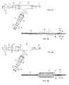
- FIG. 3Ashows a side view of a luer assembly 20 having one or more valves (in either an opened or closed configuration) and filters coupled thereto for use in sterilizing the catheter assembly.
- Fig. 3Bshows a partial cross-sectional side view of an inflation balloon assembly 12 coupled to the catheter 14 having luer assembly 20 and further having a mandrel assembly 38 blocking the catheter lumen for use in sterilizing the catheter assembly.
- An inflation valve assembly 26e.g., uni-directional valve or stopcock, having a stop or valve 28 operable between a closed and opened configuration may have an inflation lumen filter assembly 34 , as described above, coupled to balloon inflation lumen 22 extending from luer assembly 20 .
- a guidewire valve assembly 30e.g., similar to valve assembly 26
- stop or valve 32may be coupled to guidewire lumen 24 .
- a guidewire lumen filter assembly 36(e.g., similar to filter assembly 34 ) may be coupled proximally to valve assembly 30 . Utilizing 0.2 ⁇ m pore filters 34, 36 may prevent the introduction of microbial contaminants into the catheter lumens.
- a removable sealis inserted in the catheter distal end to seal the distal portion of the catheter assembly.
- An example of such a removable sealis shown in mandrel assembly 38 which may utilize a mandrel 44 sized for insertion within a guidewire lumen 24 of catheter 14 .
- a flared seal portion 46which extends proximally over mandrel 44 may be attached near or at a distal end of mandrel 44 along attachment 48 such that when mandrel 44 is inserted within guidewire lumen 24 through distal opening 40 , flared seal portion 46 may extend at least partially over catheter distal tip 42 and upon the catheter outer surface to form a seal effectively isolating the catheter lumen 24 from the environment.
- respective stops 28, 32may be turned or configured into an opened configuration such that the catheter lumens are in fluid communication with the environment through filters 34, 36 , as shown in Fig. 3A . Sterilization of the internal catheter lumens may be then achieved utilizing any of the methods described herein, e.g., ETO sterilization, or any other suitable sterilization methods. Alternatively, stops 28, 32 may be turned or configured into their closed configurations and sterilization of the internal catheter lumens may nonetheless be achieved using other sterilization methods, e.g., E-beam sterilization.
- the catheter assemblymay be moved into a controlled aseptic environment, such as a clean room, where one or both stops 28, 32 may be closed (if sterilized in their opened configuration, otherwise, they may be left closed).
- a controlled aseptic environmentsuch as a clean room
- stops 28, 32may be closed (if sterilized in their opened configuration, otherwise, they may be left closed).
- the stop 28 on inflation valve assembly 26may be opened (or left opened) and air or another fluid may be passed through filter 34 to at least partially inflate balloon 12 , as shown in respective Figs. 4A and 4B . Because the inflation lumen 22 was pre-sterilized, passing the air or fluid through the filter 34 may maintain sterility of the lumen 22 and balloon 12 .
- the polymeric stent 10(which may be pre-sterilized) may be crimped upon the balloon 12 , as shown in Fig. 4B , and stop 28 may then be turned into its closed configuration to again effectively isolate and maintain the lumen sterility.
- both the stops 28, 32 for respective inflation and guidewire lumens 22, 24may be opened and coupled to an air or fluid source and pressurized. Because any air or fluid passes through respective filter assemblies 34, 36 , sterility of the catheter lumens may still be maintained.
- one or both filter assemblies 34, 36may be removed and the catheter assembly packaged, as shown in Figs. 5A and 5B .
- the entire assembly (or the external components)may then be terminally sterilized utilizing any of the methods described herein.
- one or both valves 26, 30(as well as mandrel assembly 38 , if not already removed) may be removed by the physician prior to stent implantation, as shown in Figs. 6A and 6B .
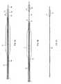
- Mandrel 44may be comprised of a material such as stainless steel which is sized to have a diameter (e.g., having an outer diameter of 0.005 in-0.080 in) which is suitable for insertion within the guidewire lumen 24 of catheter 14 .
- Mandrel 44may have a length (e.g., 1 cm-160 cm) which is varied so long as the mandrel 44 may extend at least partially through the balloon 12 as the mandrel 44 may provide structural integrity to the catheter 14 during stent crimping upon the balloon 12 .
- the increased structural strength provided by the mandrel 44 to catheter 14may inhibit or prevent the catheter from buckling as the stent 10 is placed and crimped thereupon.
- Seal 46(which may be comprised of an elastic material such silicone, latex, Pebax®, etc.) may be attached 48 (e.g., via adhesive) near or at a distal end of mandrel 48 and flare proximally such that the seal 46 forms a tubular structure (e.g., having an outer diameter of 0.007 in-0.090 in and an inner diameter of 0.005 in-0.090 in) which may slidingly receive the distal end 42 of the catheter 14 while mandrel 44 is inserted into the guidewire lumen 24 .
- mandrel assembly 38With mandrel assembly 38 securely positioned through the distal opening 40 of catheter 14 and over the distal tip 42 , fluid communication is inhibited or prevented between the guidewire lumen 24 and the environment, as shown in Fig. 7A .
- mandrel assembly 38may be removed by sliding mandrel 44 distally through opening 40 from lumen 24 , as shown in Fig. 7B.
- Fig. 7Cillustrates the mandrel assembly 38 completely removed from the catheter 14 .
- a plug member 50 having a tapered portion 52 extending proximally along mandrel 44may be attached near or at a distal end of mandrel 44 .
- the tapered portion 52may be inserted into the distal opening 40 as mandrel 44 is slid into the guidewire lumen 24 to effectively plug the catheter tip.
- the plug member 50may be comprised of a polymeric material such as silicone, Pebax®, etc. which conforms to the catheter opening 40 .
- Fig. 8Billustrates the mandrel assembly being removed from the guidewire lumen
- Fig. 8Cshows the mandrel assembly removed entirely from the catheter.
- Figs. 9A to 9Cshow yet another example of a mandrel assembly.
- mandrel 44may be comprised of a mandrel having an integrated tapered section 54 extending into a widened section 56 near or at a distal end of the mandrel.
- the mandrelmay be comprised of stainless steel, as above, or a relatively high-durometer polymer, or any other suitable material.
- Figs. 9B and 9Cillustrate the partial removal of the mandrel and the mandrel completely removed from the catheter.
- the implanted stent 10may desirably achieve or maintain mechanical characteristics which are either enhanced or at the least unaffected by the sterilization methods.
- the stent 10may achieve or maintain at least one (and desirably all) of the following characteristics, e.g., a diameter increase by 5%-80% via the inflatable balloon 12 without fracture formation; may curve up to 180° about a 1 cm curvature radius without fracture formation; exhibit a percent reduction in axial length of between 10%-50% without fracture formation when placed under an axial load; exhibit a percent reduction in diameter of between 5%-70% without fracture formation when placed under a compressive load; and exhibit a 20% radial deformation when placed under a load of 0.1 N-5 N.
- a diameter increase by 5%-80% via the inflatable balloon 12 without fracture formationmay curve up to 180° about a 1 cm curvature radius without fracture formation; exhibit a percent reduction in axial length of between 10%-50% without fracture formation when placed under an axial load; exhibit a percent reduction in diameter of between 5%-70% without fracture formation when placed under a compressive load; and exhibit a 20% radial deformation when placed under a load of 0.1 N-5 N.
- the fully sterilized stentmay be able to maintain its original crystallinity of 25%-35% and a molecular weight of 259,000 g/mol to 2,120,000 g/mol while providing high radial strength (e.g., 0.1 N-5 N per 1 cm length at 20% compression), withstanding considerable amounts of strain without fracturing (e.g., 150% strain), and exhibiting high fatigue life under physiological conditions (e.g, 10 million cycles under radial pulse load), 200,000 - 1 million cycles under axial compression and torsional loads.
- high radial strengthe.g., 0.1 N-5 N per 1 cm length at 20% compression
- high fracturinge.g., 150% strain
- high fatigue life under physiological conditionse.g, 10 million cycles under radial pulse load
- 200,000 - 1 million cycles under axial compression and torsional loadse.g. 10 million cycles under radial pulse load
- the balloonmay be inflated and stent mounted onto the inflated balloon prior to pre-sterilization.
- the assemblymay be then sterilized using ETO sterilization with an operating temperature range of 38°-50° C and RH of 20%-80%.
- the stentmay be subsequently crimped on to the balloon in an aseptic or semi-aseptic environment and terminally sterilized by using VHP sterilization.
- the purpose of presterilization of the inflated balloonis to eliminate the need for inflation during the crimping process, thus reducing the potential for introduction of bacterial load.
- the bioabsorbable polymeric stentmay be selected from the group consisting of polyethylene, polycarbonates, polyamides, polyesteramides, polyetheretherketone, polyacetals, polyketals, polyurethane, polyolefin, polyethylene terephthalate, polylactide, poly-L-lactide, poly-glycolide, poly(lactide-co-glycolide), polycaprolactone, caprolactones, polydioxanones, polyanhydrides, polyorthocarbonates, polyphosphazenes, chitin, chitosan, poly(amino acids), polyorthoesters, oligomers, homopolymers, methyl cerylate, methyl methacrylate, acryli acid, methacrylic acid, acrylamide, hydroxyethy acrylate, hydroxyethyl methacrylate, glyceryl scrylate, glyceryl methacrylate, meth
Landscapes
- Health & Medical Sciences (AREA)
- Life Sciences & Earth Sciences (AREA)
- Veterinary Medicine (AREA)
- Public Health (AREA)
- General Health & Medical Sciences (AREA)
- Animal Behavior & Ethology (AREA)
- Epidemiology (AREA)
- General Chemical & Material Sciences (AREA)
- Chemical & Material Sciences (AREA)
- Chemical Kinetics & Catalysis (AREA)
- Engineering & Computer Science (AREA)
- Biomedical Technology (AREA)
- Oral & Maxillofacial Surgery (AREA)
- Cardiology (AREA)
- Vascular Medicine (AREA)
- Transplantation (AREA)
- Heart & Thoracic Surgery (AREA)
- Materials For Medical Uses (AREA)
- Apparatus For Disinfection Or Sterilisation (AREA)
- Prostheses (AREA)
- Media Introduction/Drainage Providing Device (AREA)
Description
- The present invention relates generally to methods and apparatus for sterilization of temperature sensitive medical devices, particularly catheter devices and implantable prostheses.
- There are several commonly known methods for terminal sterilization, including, dry heat, steam autoclave, ethylene oxide (EO) and radiation (gamma and E-beam). There are also newer sterilization options that utilize hydrogen peroxide (H2O2) vapor which are effective sterilization methods for highly resistant spore formers, non-spore forming bacteria and other microorganisms.
- However, many of these traditional sterilization methods suffer from a number of limitations which reduce their effectiveness. For instance, the application of dry heat is typically conducted at 160-170° C for a minimum of two hours but due to its high temperature requirement, its application is highly limited for temperature-sensitive devices and instruments.
- Another sterilization method utilizes steam autoclave which is the oldest and typically most cost-effective method of sterilization used mostly for surgical instruments. The applied steam reaches 121-148 ° C in a pressure chamber at 15 PSI. The sterilization period is dependent on the temperature and size of the load and can range from 10-60 minutes. Yet because this method utilizes relatively high temperatures, it is not well suited for heat sensitive materials, devices, and instruments.
- Another methods utilizes Ethylene Oxide (ETO) gas for items that are heat or moisture sensitive. Although the operating temperature of this process is far below those of dry heat and steam autoclave sterilization, it may still be too high for a certain medical devices, namely bioabsorbable stents.
- Gamma and E-beam sterilization is another method which uses radiation where the effect on polymeric materials is the same for both. Gamma and E-beam sterilization typically subjects devices to irradiation sterilization but polymeric devices, in particular, will inevitably be affected by the radiation and will experience changes in their polymer structure (such as chain scission and cross-linking). These processes may lead to significant changes and compromise in the tensile strength, elongation at break, and yield strain of such polymeric devices. Furthermore, the exact changes in mechanical properties may not be immediately apparent as there can be some time delay in the development of these changes.
- Another sterilization further includes Vaporized Hydrogen Peroxide (VHP) sterilization which has been generally applied for sterilizing medical devices in hospitals worldwide. Sterilization by VHP occurs in a relatively low-moisture environment at a temperature less than 50C. It is generally suitable for sterilizing heat and moisture-sensitive items and delicate instruments. Hydrogen Peroxide is an oxidizing agent that effects sterilization thru oxidation of key cellular components (e.g. membrane lipids, DNA, and other essential constituents). These chemical interactions at multiple biologically important reaction sites are believed to be responsible for the inactivation of microorganisms. As a low-temperature gaseous method of sterilization, VHP is an alternative to ETO sterilization but VHP sterilization does not penetrate into the devices to be sterilized as much as ETO. However, besides low-temperature and moisture, VHP sterilization does offer other significant advantages over ETO sterilization including excellent material compatibility and short cycle time. Yet like other sterilization modalities, VHP has limitations. Because VHP sterilization lacks the penetration available with ETO, an open gas pathway must be present. Medical devices such as PTCA or PTA catheters with or without stents mounted on to the delivery catheters may comprise relatively long tubular members in a range of 100-150 cm with luminal diameters as small as 0.008". Such configurations present a significant challenge for this method of sterilization as VHP sterilization is generally incapable of penetrating and sterilizing though these lumen lengths.
- Because of these limitations, there is a need for a method that is capable of sterilizing devices with complex geometry and high-sensitivity to temperature and radiation exposure.
US 2005/107738 A1 discloses a fluid delivery catheter, comprising: an elongate, flexible tubular body, having a proximal end and a distal end; an infusion lumen extending through the body from the proximal end in the direction of the distal end; at least two infusion ports on the tubular body; and an inflatable tube within the tubular body. At least one infusion port is in communication with the infusion lumen when the inflatable tube is in a first inflation state, and the infusion port is isolated from the infusion lumen when the inflatable tube is in a second inflation state.- According to a first aspect of the present invention there is provided the system of claim 1.
- According to a second aspect of the present invention there is provided the method of claim 8.
- Bioabsorbable polymeric stents are especially sensitive to temperature, radiation, and moisture present in traditional sterilization processes. It is known that temperatures used during sterilization, e.g., ETO sterilization, can result in cracking of polymeric stent struts during stent deployment due to onset of brittle behavior.
- A stent may be constructed of a bioabsorbable polymeric material with a Tg (glass transition temperature) between 40-80° C. While in an expanded form, this stent may be first exposed to an ETO sterilization process with, e.g., an operating temperature range of 38° - 50° C and with a relative humidity (RH) of 20% - 80%. Since this sterilization temperature is at or below the Tg of the stent material, undesirable thermal effects and deterioration of mechanical properties may be largely avoided. The stent may be subsequently crimped on to a pre-sterilized catheter delivery system in an aseptic or semi-aseptic environment. The assembly may then undergo a terminal sterilization step utilizing, e.g., a vaporized hydrogen peroxide (VHP) sterilization method. Because of the low temperature and RH levels of the VHP sterilization process, mechanical properties of the stent may not be adversely affected. To further preserve mechanical properties of stent, an example of the VHP sterilization process parameters may be set as follows: (1) temperature range below 60° C, (2) cycle time of 1 hr - 10 hrs, and (3) concentration of 50%-60% normal peroxide by weight.
- Aside from ETO or VHP sterilization, a nitrous oxide based sterilization method may also be utilized such as those commercially available from Noxilizer (Bethesda, MD). The catheter assembly may be exposed to nitrous oxide, e.g., from 10 minutes to 1 hour and at a maximum temperature of 23° C. The exposure time can be increased as necessary to ensure complete device sterilization.
- A system and method for maintaining the sterility of catheter lumens incorporates the use of one or more filters coupled to a valve. The one or more filters may, for example, be 0.2 µm pore filters. A luer assembly having one or more valves (in either an opened or closed configuration) and the filter(s) coupled thereto may be used for sterilizing the catheter assembly. Furthermore, a mandrel is used for blocking the catheter lumen for use in sterilizing the catheter assembly.
- An inflation valve assembly, e.g., uni-directional valve or stopcock, having a stop or valve operable between a closed and opened configuration may have an inflation lumen filter assembly coupled to the balloon inflation lumen extending from the luer assembly. Likewise, a guidewire valve assembly having a stop or valve may be coupled to the guidewire lumen. A guidewire lumen filter assembly may be coupled proximally to the valve assembly. Utilizing 0.2 µm or smaller pore filters may prevent the introduction of microbial contaminants into the catheter lumens.
- A removable seal is inserted in the catheter distal end to also seal the distal portion of the catheter assembly. An example of such a removable seal is a mandrel sized for insertion within a guidewire lumen of the catheter. A flared seal portion which extends proximally over the mandrel may be attached near or at a distal end of the mandrel such that when the mandrel is inserted within the guidewire lumen through a distal opening, the flared seal portion may extend at least partially over the catheter distal tip and upon the catheter outer surface to form a seal effectively isolating the catheter lumen from the environment and preventing introduction of microbial contaminants into the lumen.
- With the valve assemblies and their respective filters coupled securely to the luer assembly, respective stops may be turned or configured into an opened configuration such that the catheter lumens are in fluid communication with the environment through the filters. Sterilization of the internal catheter lumens may be then achieved utilizing any of the methods described herein, e.g., ETO sterilization, or any other suitable sterilization methods. Alternatively, the stops may be turned or configured into their closed configurations and sterilization of the internal catheter lumens may nonetheless be achieved using other sterilization methods, e.g., E-beam sterilization.
- Once the sterilization of the catheter lumens has been completed, the catheter assembly may be moved into a controlled aseptic environment, such as a clean room, where one or both stops may be closed (if sterilized in their opened configuration, otherwise, they may be left closed). With the proximal end of the catheter effectively isolated by the luer assembly and the distal end of the catheter effectively isolated by the mandrel assembly, the internal catheter lumens may maintain their sterility.
- To place a stent upon the inflation balloon after catheter sterilization, the stop on the inflation valve assembly may be opened (or left opened) and air or another fluid may be passed through the filter to at least partially inflate the balloon. Because the inflation lumen was pre-sterilized, passing the air or fluid through the filter may maintain sterility of the lumen and balloon. The polymeric stent (which may be pre-sterilized) may be crimped upon the balloon and the stop may then be turned into its closed configuration to again effectively isolate and maintain the lumen sterility.
- Optionally, if the catheter system requires any further inspection or testing, such as pressure testing for ensuring the absence of leaks, both the stops for respective inflation and guidewire lumens may be opened and coupled to an air or fluid source and pressurized. Because any air of fluid passes through the respective filter assemblies, sterility of the catheter lumens may still be maintained.
- With the stent crimped the balloon and the internal catheter lumens sterilized, one or both filter assemblies may be removed and the catheter assembly packaged. The entire assembly (or the external components) may then be terminally sterilized utilizing any of the methods described herein. Prior to the catheter assembly being used by the physician, one or both valves may be removed by the physician prior to stent implantation.
- Turning back now to pre-conditioning and/or sterilization processes, another variation is described which achieves or maintains particular post-sterilization mechanical properties of the stent. The implanted stent may desirably achieve or maintain mechanical characteristics which are either enhanced or at the least unaffected by the sterilization methods. For instance, the
stent 10 may achieve or maintain at least one (and desirably all) of the following characteristics, e.g., a diameter increase by 5%-80% via theinflatable balloon 12 without fracture formation; may curve up to 180° about a 1 cm curvature radius without fracture formation; exhibit a percent reduction in axial length of between 10%-50% without fracture formation when placed under an axial load; exhibit a percent reduction in diameter of between 5%-70% without fracture formation when placed under a compressive load; and exhibit a 20% radial deformation when placed under a load of 0.1 N-5 N. - Depending on the molecular weight and crystallinity combination of the stent materials chosen, the fully sterilized stent may be able to maintain its original crystallinity of 25%-35% and a molecular weight of 259,000 g/mol to 2,120,000 g/mol while providing high radial strength (e.g., 0.1 N-5N per 1 cm length at 20% compression), withstanding considerable amounts of strain without fracturing (e.g., 150% strain), and exhibiting high fatigue life under physiological conditions (e.g, 10 million cycles under radial pulse load), 200,000 - 1 million cycles under axial compression and torsional loads.
- Examples of stents and methods of processing stents having such mechanical properties which may be produced utilizing the sterilization processes herein are shown and described in further detail in
U.S. Pat. App. 12/143,659 filed June 20, 2008 12/488,453 filed June 19, 2009 - In yet another variation, the balloon may be inflated and stent mounted onto the inflated balloon prior to pre-sterilization. The assembly may be then sterilized using ETO sterilization with an operating temperature range of 38°-50° C and RH of 20%-80%. The stent may be subsequently crimped on to the balloon in an aseptic or semi-aseptic environment and terminally sterilized by using VHP sterilization. The purpose of pre-sterilization of the inflated balloon is to eliminate the need for inflation during the crimping process, thus reducing the potential for introduction of bacterial load.
Fig. 1 shows a side view of an example of a polymeric stent which may be sterilized.Fig. 2 shows a side view of a polymeric stent crimped upon a sterilized balloon assembly which may be sterilized as a system.Fig. 3A shows a side view of a luer assembly having one or more valves (in either an opened or closed configuration) and filters coupled thereto for use in sterilizing the catheter assembly.Fig. 3B shows a partial cross-sectional side view of an inflation balloon assembly coupled to a catheter and having a mandrel assembly blocking the catheter lumen for use in sterilizing the catheter assembly.Figs. 4A and 4B show respective luer (having an inflation lumen opened) and balloon assemblies with a polymeric stent crimped onto the balloon for sterilization.Figs. 5A and 5B show respective luer (having the valves closed and filters removed) and balloon assemblies fully sterilized.Figs. 6A and 6B show respective luer (having valves removed) and balloon assemblies ready for use.Figs. 7A and 7B show partial cross-sectional side views of one variation of the mandrel assembly removed from the distal tip of the catheter.Fig. 7C shows a partial cross-sectional side view of the mandrel assembly having a flared seal for placement over the catheter distal end.Figs. 8A and 8B show partial cross-sectional side views of another variation of the mandrel assembly removed from the distal tip of the catheter.Fig. 8C shows a partial cross-sectional side view of the mandrel assembly having a plug assembly for insertion into the catheter distal end.Figs. 9A and 9B show partial cross-sectional side views of another variation of the mandrel assembly removed from the distal tip of the catheter.Fig. 9C shows a partial cross-sectional side view of the mandrel assembly having a tapered portion for insertion into the catheter distal end.- Medical devices including catheter delivery devices and implantable stents must be able to withstand mechanical loads that are imposed during delivery to the treatment site (such as loads imposed during intravascular delivery) as well as post implantation. These loads may be in forms of pulsatile, torsional, axial, compressive and/or combination thereof with various frequencies and amplitudes depending upon the site of implantation. Stents should ideally maintain their scaffolding properties and structural strength and integrity under these loading conditions. Thus, any compromise of their physical properties during sterilization may result in a mechanical failure pre or post implantation.
- Bioabsorbable polymeric stents are especially sensitive to temperature, radiation, and moisture present in traditional sterilization processes. It is known that temperatures used during ETO sterilization can result in cracking of polymeric stent struts during stent deployment due to onset of brittle behavior.
- A stent may be constructed of a bioabsorbable polymeric material with a Tg (glass transition temperature) between 40-80° C. While in an expanded form, this stent may be first exposed to an ETO sterilization process with, e.g., an operating temperature range of 38° - 50° C and with a relative humidity (RH) of 20% - 80%. Since this sterilization temperature is at or below the Tg of the stent material, undesirable thermal effects and deterioration of mechanical properties may be largely avoided.
Fig. 1 shows a side view of an example of astent 10 having at a first diameter D1 which has been sterilized prior to assembly upon a catheter.Stent 10 may be subsequently crimped on to a pre-sterilized catheter delivery system in an aseptic or semi-aseptic environment. The final assembly from this process may result in bioburden levels of 0 - 1000 colony forming units (CFU), which is a measure of viable bacterial numbers. - The assembly may then undergo a terminal sterilization step utilizing, e.g., a vaporized hydrogen peroxide (VHP) sterilization method.
Fig. 2 shows a side view of thestent 10 crimped upon the delivery system, e.g.,stent 10 may be assembled withdelivery catheter 14 in an aseptic environment wherestent 10 may be crimped upon aninflatable balloon 12 from its initial diameterD1 to a second smaller diameterD2. Because the bacterial load present on the device is very low prior to this process, and also because certain components of the system which are challenging to sterilize (which may include the catheter lumen) have been pre-sterilized by conventional methods, the final VHP sterilization process may not require full penetration through the entire assembly (including the catheter lumen). Accordingly, such a sterilization process may be highly effective as a terminal process. Furthermore, because of the low temperature and RH levels of the VHP sterilization process, mechanical properties of the stent may not be adversely affected. To further preserve mechanical properties of stent, an example of the VHP sterilization process parameters may be set as follows: (1) temperature range below 60° C, (2) cycle time of 1 hr - 10 hrs, and (3) concentration of 50%-60% normal peroxide by weight. - Aside from ETO or VHP sterilization, a nitrous oxide based sterilization method may also be utilized such as those commercially available from Noxilizer (Bethesda, MD). The catheter assembly may be exposed to nitrous oxide, e.g., from 10 minutes to 1 hour and at a maximum temperature of 23° C. The exposure time can be increased as necessary to ensure complete device sterilization.
- In order to maximize the sterilization potential of the nitrous oxide, sterilization of the catheter assembly could be accomplished in dual phases. The delivery system may be first sterilized using radiation, E-beam, or other method such as ETO sterilization. The stent may then be placed upon the sterilized catheter and the entire assembly may then be sterilized with nitrous oxide at heat levels no greater than room temperatures, e.g., 22 °C. Because of the reduced heating levels, the reduced temperatures reduce the possibility of polymer material cross-linking and the polymer glass transition temperature is not impacted. Moreover, use of nitrous oxide may require less aeration time and will not impact any shape memory properties of the polymer stents.
- As previously indicated, upon completion of the initial sterilization, the stent crimping process may be performed. The crimping process may involve the introduction of gases or fluids or other foreign materials (e.g., for balloon inflation) or tools such as mandrels into the internal lumens of the device. Yet introduction of foreign materials into a sterilized component may violate sterility of these areas. This may be especially problematic when the terminal sterilization does not have the capacity to penetrate through the walls of the device, e.g., through the catheter walls to sterilize these lumens.
- An embodiment for maintaining the sterility of catheter lumens may incorporate the use of one or more micro-porous filters (e.g., 0.2 µm pore filters) coupled to a valve. An example is shown in the side view of
Fig. 3A which shows a side view of a luer assembly20 having one or more valves (in either an opened or closed configuration) and filters coupled thereto for use in sterilizing the catheter assembly.Fig. 3B shows a partial cross-sectional side view of aninflation balloon assembly 12 coupled to thecatheter 14 having luer assembly20 and further having a mandrel assembly38 blocking the catheter lumen for use in sterilizing the catheter assembly. - An
inflation valve assembly 26, e.g., uni-directional valve or stopcock, having a stop or valve28 operable between a closed and opened configuration may have an inflation lumen filter assembly34, as described above, coupled to balloon inflation lumen22 extending from luer assembly20. Likewise, a guidewire valve assembly30 (e.g., similar to valve assembly26) having stop or valve32 may be coupled toguidewire lumen 24. A guidewire lumen filter assembly36 (e.g., similar to filter assembly34) may be coupled proximally to valve assembly30. Utilizing 0.2 µm pore filters34, 36 may prevent the introduction of microbial contaminants into the catheter lumens. - A removable seal is inserted in the catheter distal end to seal the distal portion of the catheter assembly. An example of such a removable seal is shown in mandrel assembly38 which may utilize a
mandrel 44 sized for insertion within aguidewire lumen 24 ofcatheter 14. A flared seal portion46 which extends proximally overmandrel 44 may be attached near or at a distal end ofmandrel 44 along attachment48 such that whenmandrel 44 is inserted withinguidewire lumen 24 through distal opening40, flared seal portion46 may extend at least partially over catheterdistal tip 42 and upon the catheter outer surface to form a seal effectively isolating thecatheter lumen 24 from the environment. - With
valve assemblies 26, 30 and theirrespective filters 34, 36 coupled securely to luer assembly20, respective stops28, 32 may be turned or configured into an opened configuration such that the catheter lumens are in fluid communication with the environment throughfilters 34, 36, as shown inFig. 3A . Sterilization of the internal catheter lumens may be then achieved utilizing any of the methods described herein, e.g., ETO sterilization, or any other suitable sterilization methods. Alternatively, stops28, 32 may be turned or configured into their closed configurations and sterilization of the internal catheter lumens may nonetheless be achieved using other sterilization methods, e.g., E-beam sterilization. - Once the sterilization of the catheter lumens has been completed, the catheter assembly may be moved into a controlled aseptic environment, such as a clean room, where one or both stops28, 32 may be closed (if sterilized in their opened configuration, otherwise, they may be left closed). With the proximal end of the
catheter 14 effectively isolated by luer assembly20 and the distal end ofcatheter 14 effectively isolated by mandrel assembly38, the internal catheter lumens may maintain their sterility. - To place a stent upon the
inflation balloon 12 after catheter sterilization, the stop28 oninflation valve assembly 26 may be opened (or left opened) and air or another fluid may be passed through filter34 to at least partially inflateballoon 12, as shown in respectiveFigs. 4A and 4B . Because the inflation lumen22 was pre-sterilized, passing the air or fluid through the filter34 may maintain sterility of the lumen22 andballoon 12. The polymeric stent10 (which may be pre-sterilized) may be crimped upon theballoon 12, as shown inFig. 4B , and stop28 may then be turned into its closed configuration to again effectively isolate and maintain the lumen sterility. - Optionally, if the catheter system requires any further inspection or testing, such as pressure testing for ensuring the absence of leaks, both the stops28, 32 for respective inflation and
guidewire lumens 22, 24 may be opened and coupled to an air or fluid source and pressurized. Because any air or fluid passes throughrespective filter assemblies 34, 36, sterility of the catheter lumens may still be maintained. - With the
stent 10 crimped theballoon 12 and the internal catheter lumens sterilized, one or bothfilter assemblies 34, 36 may be removed and the catheter assembly packaged, as shown inFigs. 5A and 5B . The entire assembly (or the external components) may then be terminally sterilized utilizing any of the methods described herein. Prior to the catheter assembly being used by the physician, one or bothvalves 26, 30 (as well as mandrel assembly38, if not already removed) may be removed by the physician prior to stent implantation, as shown inFigs. 6A and 6B . - Turning now to
Figs. 7A to 7C , one example of the mandrel assembly38 for sealing the distal end of the catheter is illustrated.Mandrel 44 may be comprised of a material such as stainless steel which is sized to have a diameter (e.g., having an outer diameter of 0.005 in-0.080 in) which is suitable for insertion within theguidewire lumen 24 ofcatheter 14.Mandrel 44 may have a length (e.g., 1 cm-160 cm) which is varied so long as themandrel 44 may extend at least partially through theballoon 12 as themandrel 44 may provide structural integrity to thecatheter 14 during stent crimping upon theballoon 12. The increased structural strength provided by themandrel 44 tocatheter 14 may inhibit or prevent the catheter from buckling as thestent 10 is placed and crimped thereupon. - Seal46 (which may be comprised of an elastic material such silicone, latex, Pebax®, etc.) may be attached48 (e.g., via adhesive) near or at a distal end of mandrel48 and flare proximally such that the seal46 forms a tubular structure (e.g., having an outer diameter of 0.007 in-0.090 in and an inner diameter of 0.005 in-0.090 in) which may slidingly receive the
distal end 42 of thecatheter 14 whilemandrel 44 is inserted into theguidewire lumen 24. With mandrel assembly38 securely positioned through the distal opening40 ofcatheter 14 and over thedistal tip 42, fluid communication is inhibited or prevented between theguidewire lumen 24 and the environment, as shown inFig. 7A . - Once sterilization is complete and/or prior to the
catheter 14 and crimpedstent 10 being inserted into the patient, mandrel assembly38 may be removed by slidingmandrel 44 distally through opening40 fromlumen 24, as shown inFig. 7B. Fig. 7C illustrates the mandrel assembly38 completely removed from thecatheter 14. - Another example of a mandrel assembly is shown in the side views of
Figs. 8A to 8C . In this variation, a plug member50 having a tapered portion52 extending proximally alongmandrel 44 may be attached near or at a distal end ofmandrel 44. The tapered portion52 may be inserted into the distal opening40 asmandrel 44 is slid into theguidewire lumen 24 to effectively plug the catheter tip. The plug member50 may be comprised of a polymeric material such as silicone, Pebax®, etc. which conforms to the catheter opening40.Fig. 8B illustrates the mandrel assembly being removed from the guidewire lumen andFig. 8C shows the mandrel assembly removed entirely from the catheter. Figs. 9A to 9C show yet another example of a mandrel assembly. In this variation,mandrel 44 may be comprised of a mandrel having an integrated tapered section54 extending into a widened section56 near or at a distal end of the mandrel. The mandrel may be comprised of stainless steel, as above, or a relatively high-durometer polymer, or any other suitable material.Figs. 9B and 9C illustrate the partial removal of the mandrel and the mandrel completely removed from the catheter.- Turning back now to pre-conditioning and/or sterilization processes, another variation is described which achieves or maintains particular post-sterilization mechanical properties of the stent. The implanted
stent 10 may desirably achieve or maintain mechanical characteristics which are either enhanced or at the least unaffected by the sterilization methods. For instance, thestent 10 may achieve or maintain at least one (and desirably all) of the following characteristics, e.g., a diameter increase by 5%-80% via theinflatable balloon 12 without fracture formation; may curve up to 180° about a 1 cm curvature radius without fracture formation; exhibit a percent reduction in axial length of between 10%-50% without fracture formation when placed under an axial load; exhibit a percent reduction in diameter of between 5%-70% without fracture formation when placed under a compressive load; and exhibit a 20% radial deformation when placed under a load of 0.1 N-5 N. - Depending on the molecular weight and crystallinity combination of the stent materials chosen, the fully sterilized stent may be able to maintain its original crystallinity of 25%-35% and a molecular weight of 259,000 g/mol to 2,120,000 g/mol while providing high radial strength (e.g., 0.1 N-5 N per 1 cm length at 20% compression), withstanding considerable amounts of strain without fracturing (e.g., 150% strain), and exhibiting high fatigue life under physiological conditions (e.g, 10 million cycles under radial pulse load), 200,000 - 1 million cycles under axial compression and torsional loads.
- Examples of stents and methods of processing stents having such mechanical properties which may be produced utilizing the sterilization processes herein are shown and described in further detail in
U.S. Pat. App. 12/143,659 filed June 20, 2008 12/488,453 filed June 19, 2009 - In yet another variation, the balloon may be inflated and stent mounted onto the inflated balloon prior to pre-sterilization. The assembly may be then sterilized using ETO sterilization with an operating temperature range of 38°-50° C and RH of 20%-80%. The stent may be subsequently crimped on to the balloon in an aseptic or semi-aseptic environment and terminally sterilized by using VHP sterilization. The purpose of presterilization of the inflated balloon is to eliminate the need for inflation during the crimping process, thus reducing the potential for introduction of bacterial load.
- In any of the variations herein, the bioabsorbable polymeric stent may be selected from the group consisting of polyethylene, polycarbonates, polyamides, polyesteramides, polyetheretherketone, polyacetals, polyketals, polyurethane, polyolefin, polyethylene terephthalate, polylactide, poly-L-lactide, poly-glycolide, poly(lactide-co-glycolide), polycaprolactone, caprolactones, polydioxanones, polyanhydrides, polyorthocarbonates, polyphosphazenes, chitin, chitosan, poly(amino acids), polyorthoesters, oligomers, homopolymers, methyl cerylate, methyl methacrylate, acryli acid, methacrylic acid, acrylamide, hydroxyethy acrylate, hydroxyethyl methacrylate, glyceryl scrylate, glyceryl methacrylate, methacrylamide, ethacrylamide, styrene, vinyl chloride, binaly pyrrolidone, polyvinyl alcohol, polycoprolactam, polylauryl lactam, polyjexamethylene adipamide, polyexamethylene dodecanediamide, trimethylene carbonate, poly(ß-hydroxybutyrate), poly(g-ethyl glutamate), poly(DTH iminocarbonate), poly(bisphenol A iminocarbonate), polycyanoacrylate, polyphosphazene, methyl cerylate, methyl methacrylate, acryli acid, methacrylic acid, acrylamide, hydroxyethy acrylate, hydroxyethyl methacrylate, glyceryl scrylate, glyceryl methacrylate, methacrylamide, ethacrylamide, and copolymers, terpolymers and combinations and mixtures thereof.
- The applications of the disclosed invention discussed above are not limited to certain processes, treatments, or placement in certain regions of the body, but may include any number of other processes, treatments, and areas of the body. Modification of the above-described methods and devices for carrying out the invention, and variations of aspects of the invention that are obvious to those of skill in the arts are intended to be within the scope of this disclosure. Moreover, various combinations of aspects between examples are also contemplated and are considered to be within the scope of this disclosure as well.
Claims (15)
- A system for maintaining the sterility of an internal lumen of a catheter of a catheter assembly, comprising:a catheter (14) having a proximal end, a distal end, and at least one lumen (24) therethrough;one or more valves (32) positioned at a proximal end of the catheter and in fluid communication with the at least one lumen, where the one or more valves are configurable between an opened and closed configuration;one or more filters (36) positioned in fluid communication with the one or more respective valves; andcharacterized in that the system further comprises a distal end seal comprising an elongate mandrel (44) which is insertable in the at least one lumen (24) at the distal end of the catheter and is removable by sliding the mandrel distally out through the distal end of the catheter, where the distal end seal isolates the at least one lumen when positioned at the distal end of the catheter.
- The system of claim 1, further comprising a luer assembly (20) coupled to the proximal end and defining a guidewire lumen (24) and an inflation lumen (22) therethrough.
- The system of claim 1, wherein the one or more valves (32) comprise a stopcock having a stop configurable between the opened and closed configuration.
- The system of claim 1, wherein the one or more filters (36) are coupled to a proximal end of the one or more respective valves (32).
- The system of claim 1, wherein the one or more filters (36) comprise a micro-porous filter, optionally wherein the micro-porous filter defines pores of 0.2 µm or less.
- The system of claim 1, wherein the elongate mandrel (44) has a flared sealing portion (46) which extends proximally over mandrel for receiving the catheter distal end, optionally wherein the mandrel either:has a length of 1 cm-160 cm; orhas a diameter sized to be slidably inserted into the at least one lumen (24); orhas a length sufficient to extend at least partially through an inflation balloon (12) positioned near or at the distal end of the catheter.
- The system of claim 1, wherein the elongate mandrel (44) either:having a plug member (50) sized for insertion into the catheter distal end; orhaving a tapered portion (52) sized for insertion into the catheter distal end.
- A method for sterilizing a catheter assembly, comprising:providing the system of claim 1;sealing the proximal end of the at least one lumen (24);sealing the distal end of the at least one lumen using the elongate mandrel (44) which is removably inserted into the distal end of the at least one lumen such that the lumen is isolated from an environment;sterilizing an interior of the at least one lumen; andsterilizing an exterior of the catheter (44).
- The method of claim 8, wherein sterilizing an interior comprises sterilizing via ethylene oxide or radiation.
- The method of claim 8, wherein sealing the proximal end comprises either:sealing a guidewire lumen (24) or an inflation lumen (22); oractuating a stop (32) from an opened to a closed configuration.
- The method of claim 8, wherein the elongate mandrel (44) is removably inserted into the distal end of the at least one lumen (24) such that a sealing portion of the mandrel occludes the distal end of the catheter, optionally wherein the elongate mandrel comprises either:a flared sealing portion (46) which receives the distal end of the catheter (14) in an occluding manner; ora plugging portion (50, 52) which occludes the distal end of the at least one lumen.
- The method of claim 8, further comprising introducing a gas or fluid into the at least one lumen (24) to at least partially inflate a balloon (12) positioned along the catheter (14) prior to sealing the proximal end.
- The method of claim 12, wherein the gas or fluid is introduced into the at least one lumen (24) through at least one corresponding filter (34) such that sterility of the lumen is maintained.
- The method of claim 13, further comprising crimping a stent (10) upon the balloon (12).
- The method of claim 14, further comprising removing the at least one filter (34).
Applications Claiming Priority (2)
| Application Number | Priority Date | Filing Date | Title |
|---|---|---|---|
| US14593209P | 2009-01-20 | 2009-01-20 | |
| PCT/US2009/069740WO2010085314A1 (en) | 2009-01-20 | 2009-12-29 | Sterilization methods and apparatus |
Publications (3)
| Publication Number | Publication Date |
|---|---|
| EP2389219A1 EP2389219A1 (en) | 2011-11-30 |
| EP2389219A4 EP2389219A4 (en) | 2012-08-08 |
| EP2389219B1true EP2389219B1 (en) | 2015-12-23 |
Family
ID=42337562
Family Applications (1)
| Application Number | Title | Priority Date | Filing Date |
|---|---|---|---|
| EP09839034.7AActiveEP2389219B1 (en) | 2009-01-20 | 2009-12-29 | Sterilization method and apparatus |
Country Status (8)
| Country | Link |
|---|---|
| US (3) | US8309023B2 (en) |
| EP (1) | EP2389219B1 (en) |
| JP (1) | JP5202740B2 (en) |
| CN (1) | CN102438692B (en) |
| AU (1) | AU2009338108B2 (en) |
| CA (1) | CA2750083C (en) |
| SG (1) | SG173055A1 (en) |
| WO (1) | WO2010085314A1 (en) |
Families Citing this family (20)
| Publication number | Priority date | Publication date | Assignee | Title |
|---|---|---|---|---|
| US6863683B2 (en) | 2001-09-19 | 2005-03-08 | Abbott Laboratoris Vascular Entities Limited | Cold-molding process for loading a stent onto a stent delivery system |
| US8333000B2 (en) | 2006-06-19 | 2012-12-18 | Advanced Cardiovascular Systems, Inc. | Methods for improving stent retention on a balloon catheter |
| EP2668934B1 (en)* | 2008-12-12 | 2017-05-10 | Abbott Laboratories Vascular Enterprises Limited | Process for loading a stent onto a stent delivery system |
| EP2389219B1 (en) | 2009-01-20 | 2015-12-23 | Amaranth Medical PTE | Sterilization method and apparatus |
| US9492587B2 (en) | 2009-04-13 | 2016-11-15 | Abbott Cardiovascular Systems Inc. | Stent made from an ultra high molecular weight bioabsorbable polymer with high fatigue and fracture resistance |
| US20110106234A1 (en)* | 2009-10-30 | 2011-05-05 | Axel Grandt | Interluminal medical treatment devices and methods |
| US20130032967A1 (en)* | 2010-05-07 | 2013-02-07 | Abbott Cardiovascular Systems Inc. | Cold ethylene oxide sterilization of a biodegradable polymeric stent |
| KR101913825B1 (en) | 2011-06-03 | 2018-10-31 | 사빅 글로벌 테크놀러지스 비.브이. | Sterilized polyetherimide/polyphenylene ether sulfone articles |
| KR101942539B1 (en) | 2011-06-03 | 2019-01-25 | 사빅 글로벌 테크놀러지스 비.브이. | Sterilized polyetherimide articles |
| WO2013043429A1 (en)* | 2011-09-19 | 2013-03-28 | Abbott Cardiovascular Systems Inc. | Cold ethylene oxide sterilization of a biodegradable polymeric stent |
| US20130289690A1 (en) | 2011-11-01 | 2013-10-31 | Hira V. Thapliyal | Personalized prosthesis and methods of use |
| CN103656701A (en)* | 2012-09-12 | 2014-03-26 | 上海微创医疗器械(集团)有限公司 | Low-temperature sterilizing method suitable for biodegradable scaffold |
| WO2014179022A1 (en) | 2013-05-03 | 2014-11-06 | Amaranth Medical Pte. | Stent delivery and deployment methods and apparatus |
| EP3033053A4 (en)* | 2013-08-16 | 2017-04-05 | Amaranth Medical PTE | Bioresorbable scaffold for treatment of bifurcation lesion |
| US9364588B2 (en) | 2014-02-04 | 2016-06-14 | Abbott Cardiovascular Systems Inc. | Drug delivery scaffold or stent with a novolimus and lactide based coating such that novolimus has a minimum amount of bonding to the coating |
| US10575975B2 (en) | 2015-04-22 | 2020-03-03 | Aneumed, Inc. | Personalized prosthesis and methods of deployment |
| USD864387S1 (en)* | 2017-05-02 | 2019-10-22 | Affera, Inc. | Catheter tip with openings |
| DK180324B1 (en)* | 2019-04-05 | 2020-11-17 | Viobac Aps | A sterilisation device for a catheter tube |
| WO2021126980A1 (en)* | 2019-12-16 | 2021-06-24 | Affera, Inc. | Pulmonary vein isolation catheters and associated devices, systems, and methods |
| CN114052825A (en)* | 2021-11-23 | 2022-02-18 | 余君 | Cardiovascular intervention device for emergency department |
Family Cites Families (8)
| Publication number | Priority date | Publication date | Assignee | Title |
|---|---|---|---|---|
| WO1983000447A1 (en)* | 1981-07-29 | 1983-02-17 | Baxter Travenol Lab | Conduit connectors having antiseptic application means |
| US5910104A (en)* | 1996-12-26 | 1999-06-08 | Cryogen, Inc. | Cryosurgical probe with disposable sheath |
| SE9702748D0 (en)* | 1997-07-18 | 1997-07-18 | Astra Ab | Barrier material |
| US20050107738A1 (en)* | 2000-07-21 | 2005-05-19 | Slater Charles R. | Occludable intravascular catheter for drug delivery and method of using the same |
| US8017074B2 (en)* | 2004-01-07 | 2011-09-13 | Noxilizer, Inc. | Sterilization system and device |
| EP1781354A4 (en)* | 2004-08-19 | 2008-04-09 | Vein Rx Inc | An occludable intravascular catheter for drug delivery and method of using the same |
| CN201061621Y (en)* | 2007-06-29 | 2008-05-21 | 中国人民解放军军事医学科学院卫生装备研究所 | Pathogen filter special for portable steam sterilizer |
| EP2389219B1 (en) | 2009-01-20 | 2015-12-23 | Amaranth Medical PTE | Sterilization method and apparatus |
- 2009
- 2009-12-29EPEP09839034.7Apatent/EP2389219B1/enactiveActive
- 2009-12-29SGSG2011052263Apatent/SG173055A1/enunknown
- 2009-12-29JPJP2011546253Apatent/JP5202740B2/ennot_activeExpired - Fee Related
- 2009-12-29AUAU2009338108Apatent/AU2009338108B2/ennot_activeCeased
- 2009-12-29USUS12/649,044patent/US8309023B2/enactiveActive
- 2009-12-29WOPCT/US2009/069740patent/WO2010085314A1/enactiveApplication Filing
- 2009-12-29CACA2750083Apatent/CA2750083C/ennot_activeExpired - Fee Related
- 2009-12-29CNCN200980155078.8Apatent/CN102438692B/ennot_activeExpired - Fee Related
- 2012
- 2012-11-07USUS13/671,211patent/US8574493B2/enactiveActive
- 2013
- 2013-07-03USUS13/934,705patent/US8858611B2/enactiveActive
Also Published As
| Publication number | Publication date |
|---|---|
| US8574493B2 (en) | 2013-11-05 |
| WO2010085314A1 (en) | 2010-07-29 |
| JP2012515572A (en) | 2012-07-12 |
| US20130294979A1 (en) | 2013-11-07 |
| US20100185270A1 (en) | 2010-07-22 |
| CN102438692A (en) | 2012-05-02 |
| US8858611B2 (en) | 2014-10-14 |
| EP2389219A4 (en) | 2012-08-08 |
| AU2009338108A1 (en) | 2011-08-11 |
| US20130138197A1 (en) | 2013-05-30 |
| CA2750083C (en) | 2014-01-28 |
| EP2389219A1 (en) | 2011-11-30 |
| CN102438692B (en) | 2014-03-12 |
| AU2009338108B2 (en) | 2013-05-16 |
| CA2750083A1 (en) | 2010-07-29 |
| JP5202740B2 (en) | 2013-06-05 |
| US8309023B2 (en) | 2012-11-13 |
| SG173055A1 (en) | 2011-08-29 |
Similar Documents
| Publication | Publication Date | Title |
|---|---|---|
| EP2389219B1 (en) | Sterilization method and apparatus | |
| JP2012515572A5 (en) | ||
| US8747738B2 (en) | Sterilization methods for medical devices | |
| US20080183181A1 (en) | Enclosed Protective Packaging | |
| US7108832B2 (en) | Sterialization methods and apparatus which employ additive-containing supercritical carbon dioxide sterilant | |
| US8157747B2 (en) | Single-use indicator for a surgical instrument and a surgical instrument incorporating same | |
| EP2344348B1 (en) | Apparatus and method for reprocessing lumened instruments | |
| US20080023346A1 (en) | Protected Stent Delivery System and Packaging | |
| US11633566B2 (en) | Curved catheter and methods for making same | |
| EP1898990A4 (en) | Security tip for vascular catheter | |
| JP2004503339A (en) | Medical equipment | |
| JP2010533558A (en) | Method and apparatus for maintaining access | |
| US20090110596A1 (en) | Sterilization methods and apparatus which employ additive-containing supercritical carbon dioxide sterilant | |
| KR20190017703A (en) | Volume expanders for endoscopes | |
| US20130032967A1 (en) | Cold ethylene oxide sterilization of a biodegradable polymeric stent | |
| CN211724345U (en) | Medical quick exchange balloon dilatation catheter | |
| WO2013043429A1 (en) | Cold ethylene oxide sterilization of a biodegradable polymeric stent | |
| JP2008029675A (en) | Balloon catheter | |
| HRP20161254A2 (en) | Sterile urinary catheter | |
| GB2498514A (en) | Introducer assembly and method of sterilising such an assembly |
Legal Events
| Date | Code | Title | Description |
|---|---|---|---|
| PUAI | Public reference made under article 153(3) epc to a published international application that has entered the european phase | Free format text:ORIGINAL CODE: 0009012 | |
| 17P | Request for examination filed | Effective date:20110819 | |
| AK | Designated contracting states | Kind code of ref document:A1 Designated state(s):AT BE BG CH CY CZ DE DK EE ES FI FR GB GR HR HU IE IS IT LI LT LU LV MC MK MT NL NO PL PT RO SE SI SK SM TR | |
| RIN1 | Information on inventor provided before grant (corrected) | Inventor name:RAMZIPOOR, KAMAL Inventor name:LEE, CHANG YEUL Inventor name:EL-NOUNOU, FOZAN O. | |
| DAX | Request for extension of the european patent (deleted) | ||
| A4 | Supplementary search report drawn up and despatched | Effective date:20120706 | |
| RIC1 | Information provided on ipc code assigned before grant | Ipc:A61M 29/00 20060101AFI20120702BHEP Ipc:A61L 2/20 20060101ALI20120702BHEP | |
| 17Q | First examination report despatched | Effective date:20131001 | |
| GRAP | Despatch of communication of intention to grant a patent | Free format text:ORIGINAL CODE: EPIDOSNIGR1 | |
| INTG | Intention to grant announced | Effective date:20150520 | |
| GRAS | Grant fee paid | Free format text:ORIGINAL CODE: EPIDOSNIGR3 | |
| GRAA | (expected) grant | Free format text:ORIGINAL CODE: 0009210 | |
| REG | Reference to a national code | Ref country code:FR Ref legal event code:PLFP Year of fee payment:7 | |
| AK | Designated contracting states | Kind code of ref document:B1 Designated state(s):AT BE BG CH CY CZ DE DK EE ES FI FR GB GR HR HU IE IS IT LI LT LU LV MC MK MT NL NO PL PT RO SE SI SK SM TR | |
| REG | Reference to a national code | Ref country code:GB Ref legal event code:FG4D | |
| REG | Reference to a national code | Ref country code:CH Ref legal event code:EP | |
| REG | Reference to a national code | Ref country code:IE Ref legal event code:FG4D | |
| REG | Reference to a national code | Ref country code:AT Ref legal event code:REF Ref document number:766258 Country of ref document:AT Kind code of ref document:T Effective date:20160115 | |
| REG | Reference to a national code | Ref country code:DE Ref legal event code:R096 Ref document number:602009035463 Country of ref document:DE | |
| REG | Reference to a national code | Ref country code:NL Ref legal event code:FP | |
| REG | Reference to a national code | Ref country code:LT Ref legal event code:MG4D | |
| PG25 | Lapsed in a contracting state [announced via postgrant information from national office to epo] | Ref country code:HR Free format text:LAPSE BECAUSE OF FAILURE TO SUBMIT A TRANSLATION OF THE DESCRIPTION OR TO PAY THE FEE WITHIN THE PRESCRIBED TIME-LIMIT Effective date:20151223 Ref country code:LT Free format text:LAPSE BECAUSE OF FAILURE TO SUBMIT A TRANSLATION OF THE DESCRIPTION OR TO PAY THE FEE WITHIN THE PRESCRIBED TIME-LIMIT Effective date:20151223 Ref country code:NO Free format text:LAPSE BECAUSE OF FAILURE TO SUBMIT A TRANSLATION OF THE DESCRIPTION OR TO PAY THE FEE WITHIN THE PRESCRIBED TIME-LIMIT Effective date:20160323 | |
| REG | Reference to a national code | Ref country code:AT Ref legal event code:MK05 Ref document number:766258 Country of ref document:AT Kind code of ref document:T Effective date:20151223 | |
| PG25 | Lapsed in a contracting state [announced via postgrant information from national office to epo] | Ref country code:GR Free format text:LAPSE BECAUSE OF FAILURE TO SUBMIT A TRANSLATION OF THE DESCRIPTION OR TO PAY THE FEE WITHIN THE PRESCRIBED TIME-LIMIT Effective date:20160324 Ref country code:FI Free format text:LAPSE BECAUSE OF FAILURE TO SUBMIT A TRANSLATION OF THE DESCRIPTION OR TO PAY THE FEE WITHIN THE PRESCRIBED TIME-LIMIT Effective date:20151223 Ref country code:SE Free format text:LAPSE BECAUSE OF FAILURE TO SUBMIT A TRANSLATION OF THE DESCRIPTION OR TO PAY THE FEE WITHIN THE PRESCRIBED TIME-LIMIT Effective date:20151223 Ref country code:LV Free format text:LAPSE BECAUSE OF FAILURE TO SUBMIT A TRANSLATION OF THE DESCRIPTION OR TO PAY THE FEE WITHIN THE PRESCRIBED TIME-LIMIT Effective date:20151223 | |
| PG25 | Lapsed in a contracting state [announced via postgrant information from national office to epo] | Ref country code:CZ Free format text:LAPSE BECAUSE OF FAILURE TO SUBMIT A TRANSLATION OF THE DESCRIPTION OR TO PAY THE FEE WITHIN THE PRESCRIBED TIME-LIMIT Effective date:20151223 Ref country code:ES Free format text:LAPSE BECAUSE OF FAILURE TO SUBMIT A TRANSLATION OF THE DESCRIPTION OR TO PAY THE FEE WITHIN THE PRESCRIBED TIME-LIMIT Effective date:20151223 | |
| REG | Reference to a national code | Ref country code:CH Ref legal event code:PL | |
| PG25 | Lapsed in a contracting state [announced via postgrant information from national office to epo] | Ref country code:IS Free format text:LAPSE BECAUSE OF FAILURE TO SUBMIT A TRANSLATION OF THE DESCRIPTION OR TO PAY THE FEE WITHIN THE PRESCRIBED TIME-LIMIT Effective date:20160423 Ref country code:EE Free format text:LAPSE BECAUSE OF FAILURE TO SUBMIT A TRANSLATION OF THE DESCRIPTION OR TO PAY THE FEE WITHIN THE PRESCRIBED TIME-LIMIT Effective date:20151223 Ref country code:AT Free format text:LAPSE BECAUSE OF FAILURE TO SUBMIT A TRANSLATION OF THE DESCRIPTION OR TO PAY THE FEE WITHIN THE PRESCRIBED TIME-LIMIT Effective date:20151223 Ref country code:RO Free format text:LAPSE BECAUSE OF FAILURE TO SUBMIT A TRANSLATION OF THE DESCRIPTION OR TO PAY THE FEE WITHIN THE PRESCRIBED TIME-LIMIT Effective date:20151223 Ref country code:SM Free format text:LAPSE BECAUSE OF FAILURE TO SUBMIT A TRANSLATION OF THE DESCRIPTION OR TO PAY THE FEE WITHIN THE PRESCRIBED TIME-LIMIT Effective date:20151223 Ref country code:SK Free format text:LAPSE BECAUSE OF FAILURE TO SUBMIT A TRANSLATION OF THE DESCRIPTION OR TO PAY THE FEE WITHIN THE PRESCRIBED TIME-LIMIT Effective date:20151223 Ref country code:PT Free format text:LAPSE BECAUSE OF FAILURE TO SUBMIT A TRANSLATION OF THE DESCRIPTION OR TO PAY THE FEE WITHIN THE PRESCRIBED TIME-LIMIT Effective date:20160426 Ref country code:PL Free format text:LAPSE BECAUSE OF FAILURE TO SUBMIT A TRANSLATION OF THE DESCRIPTION OR TO PAY THE FEE WITHIN THE PRESCRIBED TIME-LIMIT Effective date:20151223 | |
| REG | Reference to a national code | Ref country code:IE Ref legal event code:MM4A | |
| REG | Reference to a national code | Ref country code:DE Ref legal event code:R097 Ref document number:602009035463 Country of ref document:DE | |
| PG25 | Lapsed in a contracting state [announced via postgrant information from national office to epo] | Ref country code:MC Free format text:LAPSE BECAUSE OF FAILURE TO SUBMIT A TRANSLATION OF THE DESCRIPTION OR TO PAY THE FEE WITHIN THE PRESCRIBED TIME-LIMIT Effective date:20151223 | |
| PLBE | No opposition filed within time limit | Free format text:ORIGINAL CODE: 0009261 | |
| STAA | Information on the status of an ep patent application or granted ep patent | Free format text:STATUS: NO OPPOSITION FILED WITHIN TIME LIMIT | |
| PG25 | Lapsed in a contracting state [announced via postgrant information from national office to epo] | Ref country code:CH Free format text:LAPSE BECAUSE OF NON-PAYMENT OF DUE FEES Effective date:20151231 Ref country code:IE Free format text:LAPSE BECAUSE OF NON-PAYMENT OF DUE FEES Effective date:20151229 Ref country code:LI Free format text:LAPSE BECAUSE OF NON-PAYMENT OF DUE FEES Effective date:20151231 Ref country code:DK Free format text:LAPSE BECAUSE OF FAILURE TO SUBMIT A TRANSLATION OF THE DESCRIPTION OR TO PAY THE FEE WITHIN THE PRESCRIBED TIME-LIMIT Effective date:20151223 | |
| 26N | No opposition filed | Effective date:20160926 | |
| REG | Reference to a national code | Ref country code:FR Ref legal event code:PLFP Year of fee payment:8 | |
| PG25 | Lapsed in a contracting state [announced via postgrant information from national office to epo] | Ref country code:SI Free format text:LAPSE BECAUSE OF FAILURE TO SUBMIT A TRANSLATION OF THE DESCRIPTION OR TO PAY THE FEE WITHIN THE PRESCRIBED TIME-LIMIT Effective date:20151223 | |
| PG25 | Lapsed in a contracting state [announced via postgrant information from national office to epo] | Ref country code:HU Free format text:LAPSE BECAUSE OF FAILURE TO SUBMIT A TRANSLATION OF THE DESCRIPTION OR TO PAY THE FEE WITHIN THE PRESCRIBED TIME-LIMIT; INVALID AB INITIO Effective date:20091229 Ref country code:BG Free format text:LAPSE BECAUSE OF FAILURE TO SUBMIT A TRANSLATION OF THE DESCRIPTION OR TO PAY THE FEE WITHIN THE PRESCRIBED TIME-LIMIT Effective date:20151223 | |
| PG25 | Lapsed in a contracting state [announced via postgrant information from national office to epo] | Ref country code:CY Free format text:LAPSE BECAUSE OF FAILURE TO SUBMIT A TRANSLATION OF THE DESCRIPTION OR TO PAY THE FEE WITHIN THE PRESCRIBED TIME-LIMIT Effective date:20151223 | |
| PG25 | Lapsed in a contracting state [announced via postgrant information from national office to epo] | Ref country code:MT Free format text:LAPSE BECAUSE OF FAILURE TO SUBMIT A TRANSLATION OF THE DESCRIPTION OR TO PAY THE FEE WITHIN THE PRESCRIBED TIME-LIMIT Effective date:20151223 Ref country code:TR Free format text:LAPSE BECAUSE OF FAILURE TO SUBMIT A TRANSLATION OF THE DESCRIPTION OR TO PAY THE FEE WITHIN THE PRESCRIBED TIME-LIMIT Effective date:20151223 | |
| PG25 | Lapsed in a contracting state [announced via postgrant information from national office to epo] | Ref country code:LU Free format text:LAPSE BECAUSE OF NON-PAYMENT OF DUE FEES Effective date:20151229 | |
| REG | Reference to a national code | Ref country code:FR Ref legal event code:PLFP Year of fee payment:9 | |
| PGFP | Annual fee paid to national office [announced via postgrant information from national office to epo] | Ref country code:NL Payment date:20171226 Year of fee payment:9 Ref country code:FR Payment date:20171227 Year of fee payment:9 | |
| PGFP | Annual fee paid to national office [announced via postgrant information from national office to epo] | Ref country code:BE Payment date:20171227 Year of fee payment:9 | |
| PGFP | Annual fee paid to national office [announced via postgrant information from national office to epo] | Ref country code:DE Payment date:20171229 Year of fee payment:9 | |
| PGFP | Annual fee paid to national office [announced via postgrant information from national office to epo] | Ref country code:IT Payment date:20171221 Year of fee payment:9 | |
| PG25 | Lapsed in a contracting state [announced via postgrant information from national office to epo] | Ref country code:MK Free format text:LAPSE BECAUSE OF FAILURE TO SUBMIT A TRANSLATION OF THE DESCRIPTION OR TO PAY THE FEE WITHIN THE PRESCRIBED TIME-LIMIT Effective date:20151223 | |
| REG | Reference to a national code | Ref country code:DE Ref legal event code:R119 Ref document number:602009035463 Country of ref document:DE | |
| REG | Reference to a national code | Ref country code:NL Ref legal event code:MM Effective date:20190101 | |
| GBPC | Gb: european patent ceased through non-payment of renewal fee | Effective date:20181229 | |
| PG25 | Lapsed in a contracting state [announced via postgrant information from national office to epo] | Ref country code:NL Free format text:LAPSE BECAUSE OF NON-PAYMENT OF DUE FEES Effective date:20190101 | |
| REG | Reference to a national code | Ref country code:BE Ref legal event code:MM Effective date:20181231 | |
| PG25 | Lapsed in a contracting state [announced via postgrant information from national office to epo] | Ref country code:FR Free format text:LAPSE BECAUSE OF NON-PAYMENT OF DUE FEES Effective date:20181231 Ref country code:IT Free format text:LAPSE BECAUSE OF NON-PAYMENT OF DUE FEES Effective date:20181229 Ref country code:DE Free format text:LAPSE BECAUSE OF NON-PAYMENT OF DUE FEES Effective date:20190702 | |
| PG25 | Lapsed in a contracting state [announced via postgrant information from national office to epo] | Ref country code:BE Free format text:LAPSE BECAUSE OF NON-PAYMENT OF DUE FEES Effective date:20181231 | |
| PG25 | Lapsed in a contracting state [announced via postgrant information from national office to epo] | Ref country code:GB Free format text:LAPSE BECAUSE OF NON-PAYMENT OF DUE FEES Effective date:20181229 | |
| REG | Reference to a national code | Ref country code:GB Ref legal event code:S28 Free format text:APPLICATION FILED | |
| REG | Reference to a national code | Ref country code:GB Ref legal event code:732E Free format text:REGISTERED BETWEEN 20201217 AND 20201223 | |
| REG | Reference to a national code | Ref country code:GB Ref legal event code:732E Free format text:REGISTERED BETWEEN 20201224 AND 20201230 | |
| REG | Reference to a national code | Ref country code:GB Ref legal event code:732E Free format text:REGISTERED BETWEEN 20201231 AND 20210106 | |
| REG | Reference to a national code | Ref country code:GB Ref legal event code:S28 Free format text:RESTORATION ALLOWED Effective date:20210126 | |
| PGFP | Annual fee paid to national office [announced via postgrant information from national office to epo] | Ref country code:GB Payment date:20241122 Year of fee payment:16 |