EP2387427B1 - Intravascular blood filter - Google Patents
Intravascular blood filterDownload PDFInfo
- Publication number
- EP2387427B1 EP2387427B1EP10732227.3AEP10732227AEP2387427B1EP 2387427 B1EP2387427 B1EP 2387427B1EP 10732227 AEP10732227 AEP 10732227AEP 2387427 B1EP2387427 B1EP 2387427B1
- Authority
- EP
- European Patent Office
- Prior art keywords
- lumen
- filter
- catheter
- carotid
- delivery
- Prior art date
- Legal status (The legal status is an assumption and is not a legal conclusion. Google has not performed a legal analysis and makes no representation as to the accuracy of the status listed.)
- Active
Links
- 239000008280bloodSubstances0.000titleclaimsdescription8
- 210000004369bloodAnatomy0.000titleclaimsdescription8
- 210000001715carotid arteryAnatomy0.000claimsdescription31
- 239000000463materialSubstances0.000claimsdescription13
- 238000001914filtrationMethods0.000claimsdescription9
- 230000004087circulationEffects0.000claimsdescription8
- 230000000717retained effectEffects0.000claimsdescription2
- 238000000034methodMethods0.000description25
- 238000011084recoveryMethods0.000description12
- 210000000709aortaAnatomy0.000description10
- 210000002376aorta thoracicAnatomy0.000description10
- 210000002321radial arteryAnatomy0.000description9
- 210000005166vasculatureAnatomy0.000description9
- 210000004013groinAnatomy0.000description8
- 210000001765aortic valveAnatomy0.000description6
- 210000002168brachiocephalic trunkAnatomy0.000description6
- 230000009977dual effectEffects0.000description6
- 210000001105femoral arteryAnatomy0.000description6
- 230000002792vascularEffects0.000description6
- 208000006011StrokeDiseases0.000description5
- 230000017531blood circulationEffects0.000description5
- HLXZNVUGXRDIFK-UHFFFAOYSA-Nnickel titaniumChemical compound[Ti].[Ti].[Ti].[Ti].[Ti].[Ti].[Ti].[Ti].[Ti].[Ti].[Ti].[Ni].[Ni].[Ni].[Ni].[Ni].[Ni].[Ni].[Ni].[Ni].[Ni].[Ni].[Ni].[Ni].[Ni]HLXZNVUGXRDIFK-UHFFFAOYSA-N0.000description5
- 229910001000nickel titaniumInorganic materials0.000description5
- 238000013459approachMethods0.000description4
- 210000004204blood vesselAnatomy0.000description4
- 230000003073embolic effectEffects0.000description4
- 238000003780insertionMethods0.000description4
- 230000037431insertionEffects0.000description4
- 230000033001locomotionEffects0.000description4
- 230000007246mechanismEffects0.000description4
- 239000002184metalSubstances0.000description4
- 210000004115mitral valveAnatomy0.000description4
- 210000003270subclavian arteryAnatomy0.000description4
- 210000003484anatomyAnatomy0.000description3
- 210000004556brainAnatomy0.000description3
- 210000001168carotid artery commonAnatomy0.000description3
- 230000002490cerebral effectEffects0.000description3
- 238000000576coating methodMethods0.000description3
- 208000037265diseases, disorders, signs and symptomsDiseases0.000description3
- 208000035475disorderDiseases0.000description3
- 238000013156embolectomyMethods0.000description3
- 210000003709heart valveAnatomy0.000description3
- 238000001356surgical procedureMethods0.000description3
- 206010061216InfarctionDiseases0.000description2
- 208000031481Pathologic ConstrictionDiseases0.000description2
- 208000010378Pulmonary EmbolismDiseases0.000description2
- 208000007536ThrombosisDiseases0.000description2
- 238000002399angioplastyMethods0.000description2
- 210000001367arteryAnatomy0.000description2
- 239000011248coating agentSubstances0.000description2
- 238000011161developmentMethods0.000description2
- 230000018109developmental processEffects0.000description2
- 239000003527fibrinolytic agentSubstances0.000description2
- 238000002513implantationMethods0.000description2
- 230000007574infarctionEffects0.000description2
- 208000028867ischemiaDiseases0.000description2
- 230000003902lesionEffects0.000description2
- 230000002093peripheral effectEffects0.000description2
- -1polypropylenePolymers0.000description2
- 230000036262stenosisEffects0.000description2
- 208000037804stenosisDiseases0.000description2
- 230000009424thromboembolic effectEffects0.000description2
- 229960000103thrombolytic agentDrugs0.000description2
- 206010002383Angina PectorisDiseases0.000description1
- 241000239290AraneaeSpecies0.000description1
- 201000001320AtherosclerosisDiseases0.000description1
- 206010003658Atrial FibrillationDiseases0.000description1
- 241001631457CannulaSpecies0.000description1
- 208000005189EmbolismDiseases0.000description1
- 102000008946FibrinogenHuman genes0.000description1
- 108010049003FibrinogenProteins0.000description1
- 208000032843HemorrhageDiseases0.000description1
- HTTJABKRGRZYRN-UHFFFAOYSA-NHeparinChemical compoundOC1C(NC(=O)C)C(O)OC(COS(O)(=O)=O)C1OC1C(OS(O)(=O)=O)C(O)C(OC2C(C(OS(O)(=O)=O)C(OC3C(C(O)C(O)C(O3)C(O)=O)OS(O)(=O)=O)C(CO)O2)NS(O)(=O)=O)C(C(O)=O)O1HTTJABKRGRZYRN-UHFFFAOYSA-N0.000description1
- 101000882917Penaeus paulensis Hemolymph clottable proteinProteins0.000description1
- 239000004698PolyethyleneSubstances0.000description1
- 239000004743PolypropyleneSubstances0.000description1
- 108010023197StreptokinaseProteins0.000description1
- 208000001435ThromboembolismDiseases0.000description1
- 108090000435Urokinase-type plasminogen activatorProteins0.000description1
- 102000003990Urokinase-type plasminogen activatorHuman genes0.000description1
- 206010053648Vascular occlusionDiseases0.000description1
- 230000001154acute effectEffects0.000description1
- 230000002785anti-thrombosisEffects0.000description1
- 229940127090anticoagulant agentDrugs0.000description1
- 239000003146anticoagulant agentSubstances0.000description1
- QVGXLLKOCUKJST-UHFFFAOYSA-Natomic oxygenChemical compound[O]QVGXLLKOCUKJST-UHFFFAOYSA-N0.000description1
- 238000013158balloon valvuloplastyMethods0.000description1
- 238000005452bendingMethods0.000description1
- 230000000747cardiac effectEffects0.000description1
- 230000030833cell deathEffects0.000description1
- 239000003795chemical substances by applicationSubstances0.000description1
- 238000010276constructionMethods0.000description1
- 210000004351coronary vesselAnatomy0.000description1
- 230000034994deathEffects0.000description1
- 230000003247decreasing effectEffects0.000description1
- 230000001419dependent effectEffects0.000description1
- 238000013461designMethods0.000description1
- 230000010339dilationEffects0.000description1
- 239000003814drugSubstances0.000description1
- 230000007831electrophysiologyEffects0.000description1
- 238000002001electrophysiologyMethods0.000description1
- 238000000605extractionMethods0.000description1
- 239000004744fabricSubstances0.000description1
- 229940012952fibrinogenDrugs0.000description1
- 238000002594fluoroscopyMethods0.000description1
- 239000012634fragmentSubstances0.000description1
- 230000006870functionEffects0.000description1
- 229960002897heparinDrugs0.000description1
- 229920000669heparinPolymers0.000description1
- 239000007924injectionSubstances0.000description1
- 238000002347injectionMethods0.000description1
- 229940004975interceptorDrugs0.000description1
- 210000005248left atrial appendageAnatomy0.000description1
- 239000000203mixtureSubstances0.000description1
- 208000010125myocardial infarctionDiseases0.000description1
- 235000015097nutrientsNutrition0.000description1
- 229920001778nylonPolymers0.000description1
- 230000008520organizationEffects0.000description1
- 229910052760oxygenInorganic materials0.000description1
- 239000001301oxygenSubstances0.000description1
- RVTZCBVAJQQJTK-UHFFFAOYSA-Noxygen(2-);zirconium(4+)Chemical compound[O-2].[O-2].[Zr+4]RVTZCBVAJQQJTK-UHFFFAOYSA-N0.000description1
- 239000002245particleSubstances0.000description1
- 230000037361pathwayEffects0.000description1
- 229920000573polyethylenePolymers0.000description1
- 229920000642polymerPolymers0.000description1
- 229920001155polypropylenePolymers0.000description1
- 230000008439repair processEffects0.000description1
- 238000007789sealingMethods0.000description1
- 238000007493shaping processMethods0.000description1
- 230000006641stabilisationEffects0.000description1
- 238000011105stabilizationMethods0.000description1
- 229960005202streptokinaseDrugs0.000description1
- 229940124597therapeutic agentDrugs0.000description1
- 238000013151thrombectomyMethods0.000description1
- 230000002885thrombogenetic effectEffects0.000description1
- 230000002537thrombolytic effectEffects0.000description1
- 230000000472traumatic effectEffects0.000description1
- 238000002604ultrasonographyMethods0.000description1
- 229960005356urokinaseDrugs0.000description1
- 208000021331vascular occlusion diseaseDiseases0.000description1
- 210000003462veinAnatomy0.000description1
Images


Classifications
- A—HUMAN NECESSITIES
- A61—MEDICAL OR VETERINARY SCIENCE; HYGIENE
- A61F—FILTERS IMPLANTABLE INTO BLOOD VESSELS; PROSTHESES; DEVICES PROVIDING PATENCY TO, OR PREVENTING COLLAPSING OF, TUBULAR STRUCTURES OF THE BODY, e.g. STENTS; ORTHOPAEDIC, NURSING OR CONTRACEPTIVE DEVICES; FOMENTATION; TREATMENT OR PROTECTION OF EYES OR EARS; BANDAGES, DRESSINGS OR ABSORBENT PADS; FIRST-AID KITS
- A61F2/00—Filters implantable into blood vessels; Prostheses, i.e. artificial substitutes or replacements for parts of the body; Appliances for connecting them with the body; Devices providing patency to, or preventing collapsing of, tubular structures of the body, e.g. stents
- A61F2/01—Filters implantable into blood vessels
- A61F2/012—Multiple filtering units
- A—HUMAN NECESSITIES
- A61—MEDICAL OR VETERINARY SCIENCE; HYGIENE
- A61F—FILTERS IMPLANTABLE INTO BLOOD VESSELS; PROSTHESES; DEVICES PROVIDING PATENCY TO, OR PREVENTING COLLAPSING OF, TUBULAR STRUCTURES OF THE BODY, e.g. STENTS; ORTHOPAEDIC, NURSING OR CONTRACEPTIVE DEVICES; FOMENTATION; TREATMENT OR PROTECTION OF EYES OR EARS; BANDAGES, DRESSINGS OR ABSORBENT PADS; FIRST-AID KITS
- A61F2/00—Filters implantable into blood vessels; Prostheses, i.e. artificial substitutes or replacements for parts of the body; Appliances for connecting them with the body; Devices providing patency to, or preventing collapsing of, tubular structures of the body, e.g. stents
- A61F2/01—Filters implantable into blood vessels
- A61F2002/018—Filters implantable into blood vessels made from tubes or sheets of material, e.g. by etching or laser-cutting
- A—HUMAN NECESSITIES
- A61—MEDICAL OR VETERINARY SCIENCE; HYGIENE
- A61F—FILTERS IMPLANTABLE INTO BLOOD VESSELS; PROSTHESES; DEVICES PROVIDING PATENCY TO, OR PREVENTING COLLAPSING OF, TUBULAR STRUCTURES OF THE BODY, e.g. STENTS; ORTHOPAEDIC, NURSING OR CONTRACEPTIVE DEVICES; FOMENTATION; TREATMENT OR PROTECTION OF EYES OR EARS; BANDAGES, DRESSINGS OR ABSORBENT PADS; FIRST-AID KITS
- A61F2230/00—Geometry of prostheses classified in groups A61F2/00 - A61F2/26 or A61F2/82 or A61F9/00 or A61F11/00 or subgroups thereof
- A61F2230/0002—Two-dimensional shapes, e.g. cross-sections
- A61F2230/0004—Rounded shapes, e.g. with rounded corners
- A61F2230/0006—Rounded shapes, e.g. with rounded corners circular
- A—HUMAN NECESSITIES
- A61—MEDICAL OR VETERINARY SCIENCE; HYGIENE
- A61F—FILTERS IMPLANTABLE INTO BLOOD VESSELS; PROSTHESES; DEVICES PROVIDING PATENCY TO, OR PREVENTING COLLAPSING OF, TUBULAR STRUCTURES OF THE BODY, e.g. STENTS; ORTHOPAEDIC, NURSING OR CONTRACEPTIVE DEVICES; FOMENTATION; TREATMENT OR PROTECTION OF EYES OR EARS; BANDAGES, DRESSINGS OR ABSORBENT PADS; FIRST-AID KITS
- A61F2230/00—Geometry of prostheses classified in groups A61F2/00 - A61F2/26 or A61F2/82 or A61F9/00 or A61F11/00 or subgroups thereof
- A61F2230/0002—Two-dimensional shapes, e.g. cross-sections
- A61F2230/0004—Rounded shapes, e.g. with rounded corners
- A61F2230/0008—Rounded shapes, e.g. with rounded corners elliptical or oval
- A—HUMAN NECESSITIES
- A61—MEDICAL OR VETERINARY SCIENCE; HYGIENE
- A61F—FILTERS IMPLANTABLE INTO BLOOD VESSELS; PROSTHESES; DEVICES PROVIDING PATENCY TO, OR PREVENTING COLLAPSING OF, TUBULAR STRUCTURES OF THE BODY, e.g. STENTS; ORTHOPAEDIC, NURSING OR CONTRACEPTIVE DEVICES; FOMENTATION; TREATMENT OR PROTECTION OF EYES OR EARS; BANDAGES, DRESSINGS OR ABSORBENT PADS; FIRST-AID KITS
- A61F2230/00—Geometry of prostheses classified in groups A61F2/00 - A61F2/26 or A61F2/82 or A61F9/00 or A61F11/00 or subgroups thereof
- A61F2230/0063—Three-dimensional shapes
- A61F2230/0067—Three-dimensional shapes conical
- A—HUMAN NECESSITIES
- A61—MEDICAL OR VETERINARY SCIENCE; HYGIENE
- A61F—FILTERS IMPLANTABLE INTO BLOOD VESSELS; PROSTHESES; DEVICES PROVIDING PATENCY TO, OR PREVENTING COLLAPSING OF, TUBULAR STRUCTURES OF THE BODY, e.g. STENTS; ORTHOPAEDIC, NURSING OR CONTRACEPTIVE DEVICES; FOMENTATION; TREATMENT OR PROTECTION OF EYES OR EARS; BANDAGES, DRESSINGS OR ABSORBENT PADS; FIRST-AID KITS
- A61F2230/00—Geometry of prostheses classified in groups A61F2/00 - A61F2/26 or A61F2/82 or A61F9/00 or A61F11/00 or subgroups thereof
- A61F2230/0063—Three-dimensional shapes
- A61F2230/0069—Three-dimensional shapes cylindrical
Definitions
- This inventionrelates generally to medical devices used during vascular intervention, and more particularly, concerns medical devices that are useful in treating aortic valve replacement, thromboembolic disorders and for removal of foreign bodies in the vascular system.
- Thromboembolic disorderssuch as stroke, pulmonary embolism, peripheral thrombosis, atherosclerosis, and the like, affect many people. These disorders are a major cause of morbidity and mortality in the United States and throughout the world. Thromboembolic events are characterized by an occlusion of a blood vessel.
- the occlusioncan be caused by a clot which is viscoelastic (jelly-like) and is comprised of platelets, fibrinogen, and other clotting proteins.
- Percutaneous aortic valve replacementhas been in development for some time now and stroke rates related to this procedure are between four and twenty percent.
- plaquemay be dislodged from the vasculature.
- the invention contained withinwill block the emboli from traveling through the carotid circulation and onto the brain.
- tissue ischemia(lack of oxygen and nutrients) develops.
- the ischemiawill progress to tissue infarction (cell death) if the occlusion persists. Infarction does not develop or is greatly limited if the flow of blood is reestablished rapidly. Failure to reestablish blood-flow can lead to the loss of limb, angina pectoris, myocardial infarction, stroke, or even death.
- Occlusion of the venous circulation by thrombileads to blood stasis which can cause numerous problems.
- the majority of pulmonary embolismsare caused by emboli that originate in the peripheral venous system. Reestablishing blood flow and removal of the thrombus is highly desirable.
- an embolectomyinvolves incising a blood vessel and introducing a balloon-tipped device (such as a Fogarty catheter) to the location of the occlusion.
- a balloon-tipped devicesuch as a Fogarty catheter
- the balloonis then inflated at a point beyond the clot and used to translate the obstructing material back to the point of incision.
- the obstructing materialis then removed by the surgeon. While such surgical techniques have been useful, exposing a patient to surgery may be traumatic and is best avoided when possible. Additionally, the use of a Fogarty catheter may be problematic due to the possible risk of damaging the interior lining of the vessel as the catheter is being withdrawn.
- a common percutaneous techniqueis referred to as balloon angioplasty where a balloon-tipped catheter is introduced into a blood vessel, typically through an introducing catheter. The balloon-tipped catheter is then advanced to the point of the occlusion and inflated in order to dilate the stenosis. Balloon angioplasty is appropriate for treating vessel stenosis but is generally not effective for treating acute thromboembolisms.
- Another percutaneous techniqueis to place a microcatheter near the clot and infuse Streptokinase, Urokinase, or other thrombolytic agents to dissolve the clot.
- StreptokinaseUrokinase
- thrombolytic agentscan cause hemorrhage and in many patients the agents cannot be used at all.
- Another problematic areais the removal of foreign bodies.
- Foreign bodies introduced into the circulationcan be fragments of catheters, pace-maker electrodes, guide wires, and erroneously placed embolic material such as thrombogenic coils.
- embolic materialsuch as thrombogenic coils.
- retrieval devices for the removal of foreign bodiescertain of such devices form a loop that can ensnare the foreign material by decreasing the size of the diameter of the loop around the foreign body. The use of such removal devices can be difficult and sometimes unsuccessful.
- systems heretofore disclosed in the artare generally limited by size compatibility and the increase in vessel size as the emboli is drawn out from the distal vascular occlusion location to a more proximal location near the heart. If the embolectomy device is too large for the vessel it will not deploy correctly to capture the clot or foreign body, and if too small in diameter it cannot capture clots or foreign bodies across the entire cross section of the blood vessel. Additionally, if the embolectomy device is too small in retaining volume then as the device is retracted the excess material being removed can spill out and be carried by flow back to occlude another distal vessel.
- filter devicesare delivered from the groin and are placed distal to the flow of the lesion or site in question.
- Single basket-type filters or Nitinol loop filtersare the most common used today in carotid stent procedures of vein graft stenting.
- the filteris delivered over the guidewire protecting the distal vasculature.
- the inventionhere may be delivered from the groin in a conventional manner to vessels such as the carotid arteries or via radial (arm vasculature) approach. Protecting the carotid arteries and cerebral vasculature system is the main goal while leaving the aortic arch free from catheters and wire as much as possible during the delivery of other devices such as aortic balloons and prosthetic valves or other associated devices.
- One method of filtering the carotid arteries leaving the aorta free from obstructionis to deliver a filter to each of the carotid arteries from the groin leaving them in the carotid vasculature and retrieving them via snare post procedure.
- a delivery catheterwould be inserted through an introducer in the groin (femoral artery) and delivered to the common carotid arteries and detached. The delivery catheter would be removed and a second filter would be delivered in a similar manner to the other carotid artery.
- two detached filtersnow in place the procedure treating the aortic or mitral valve can now be completed with embolic protection for the cerebral vascular system. Once the procedure to the valve is completed, the filters can be snared and retrieved back out the femoral artery as they were delivered. Any embolic particles will be captured in the filter device and removed safely from the body.
- Another method for filtering the carotid arterieswould be to deliver a filter from the femoral artery and utilize a single catheter to house the two attachment means to the filters.
- These attachmentsmay be a wire similar to a guidewire or a hypo-tube to connect the filter element to an external portion of the body. Keeping these wires or connection means organized and contained within a single or dual lumen catheter will help organize and limit potential entanglement with other catheters being delivered to the target site such as the aortic valve or other cardiac elements including but not limited to the mitral valve and coronary arteries.
- the distal portion of the cathetermay have a single exit portion or a staggered exit to allow an exit at different points along the catheter.
- One exit portmay be at the distal most end of the catheter and the other may be a centimeter proximal from this to allow the attachment wire to exit near the left common carotid artery. Furthermore, there could be an extension to the distal most portion of the catheter allowing side ports for both wires to exit. This would allow for additional catheter stabilization within the aorta.
- Another embodimentwould deliver filters to the carotid from the radial artery and allow for a clear aortic arch from catheters and other delivery means from a more conventional femoral delivery means. From this access site a plurality of filters could be delivered through a common access sheath or the filters could be delivered from a dual lumen catheter with each lumen housing a single filter.
- Another delivery meanswould utilize a single catheter with filters mounted in a coaxial manner where the distal filter would be delivered first and could be mounted to a wire where the second would be mounted to a hypo-tube where the first filters wire would run through the second allowing for relative motion between the two filters.
- the first filterwould be delivered to the left common carotid from the radial artery and the second would be delivered to the right common carotid artery or the brachiocephalic trunk in a coaxial manner.
- These filterswould be opposed in direction as the distal filter would be filtering blood flowing from the base of the aorta to the head and toward the distal end of the guidwire.
- the proximal filterwould be filtering blood from the base of the aorta to the head and toward the proximal end of the guidewire., Placing the two filters together there would be a conical shape configuration where the large diameter portions of the cones would meet. These two filters would be delivered in a collapsed configuration and expanded when expelled from the delivery catheter. Retrieval would be a retraction of the filter back into a recovery catheter that would be a larger inner diameter than the delivery catheter to allow room for particulate. Being opposed in capture direction the right carotid would be the first filter that would be recovered by an expanded sheath where the embolic material would not be disturbed and further withdrawn to a smaller sheath for removal from the body.
- the expanded sheathcould be constructed from braided Nitinol wire pre-shaped so when exposed the braid would expand to receive the filter without squeezing out any trapped emboli.
- the second or left carotid filterwould be recovered in a conventional manner where the larger diameter would be pulled into a sheath to trap and remove the emboli within the tail or distal portion of the filter.
- Another means to deliver the filters via radial artery approachwould be to utilize a dual lumen catheter where each lumen would house a single filter.
- the first lumenwould deliver a filter to the left carotid artery and the second lumen would deliver a filter to the right carotid artery.
- the lumenscould be staggered in length to reach each ostium in which case the first or left filter lumen would be longer in length to allow for placement distal from the second filter placement in the right carotid.
- the second lumenmay be pre-shaped with a curve to allow easy access to the right carotid artery.
- This pre-shaped curvemay be retained in a straighter manner to allow for delivery and released to express the delivery shape when at the bifurcation of the subclavian and the carotid artery.
- an active shapingwhere the curve is directed external to the body by a handle mechanism such as a pull-wire where tension would generate a compressive force to the catheter column preferentially bending the lumen.
- Recoverycould utilize the same dual lumen concept or utilize a second recovery sheath independently from one another.
- Another application for this device and methodwould be for surgical operations where the patient may be put on heart-lung bypass.
- cross clamping of the aorta catheters or wires in the aortamay interfere with the procedure and allow leakage of blood around the cannulas used.
- additional antithrombotic coatings to the filtercould allow for an extended implantation time allowing filtration time to be extended post procedure.
- An example of this coatingwould be Heparin. Placement of these catheters and filters could be under fluoroscopy or ultrasound guidance to direct proper filter placement. Radiopaque markers may add necessary visibility to the catheter, filter and or wires.
- Another surgical delivery meanswould be an insertion to the carotid artery via the neck.
- the filtercould face either antigrade or retrograde depending upon the placement insertion point or access site. This would allow for complete filtration without any aortic interference as the entire devices would be within the carotid circulation.
- the puncture sitewould be very small and recovery could be through the entry site or through the groin as the filter could be inserted distal to meet a recovery sheath in the aorta. With this groin recovery any emboli within the proximal carotid would be captured before later dislodgement.
- Intravascular filtershave been used in many configurations ranging from a windsock style as commercialized as the FilterWire from Boston Scientific or the ACCUNET from Abbott Vascular or the Spider from eV3. These filters utilize a memory metal such as Nitinol is used to oppose the vascular wall tightly sealing any emboli from passage while a filter material such as a porous fabric material retains and emboli from passing distally from the device.
- a memory metalsuch as Nitinol is used to oppose the vascular wall tightly sealing any emboli from passage while a filter material such as a porous fabric material retains and emboli from passing distally from the device.
- a laser cut memory metalwhere the basket is the frame and the filter is used to trap emboli when expanded.
- Another exampleis constructed from a braided wire such as Medtronic's Interceptor PLUS where once exposed the braid expands to create a funnel or cone shape to trap emboli and the proximal or larger end is pre-shaped to accept blood flow with larger openings heat-set into the memory metal such as Nitinol.
- These filtersrange in diameter from about 2-15 mm in diameter and are approximately 20-30 mm in length. They are generally attached to a guidewire and sheathed for delivery and resheathed for recovery. The catheter profile measures about 1 to 2 mm in diameter and has a length of about 90 to 200 cm.
- Catheter constructionis normally a polypropylene or polyethylene material but nylons and blends can be used as well. All devices are considered single use and are commonly placed for carotid stenting or savenous veign grafts stenting.
- a filterwould be placed into the carotid arteries to protect the circulation to the brain where emboli could induce a stroke and leave the patient debilitated. Placement of these filters to the patient's carotid circulation would be most convenient if it occurred without obstruction of the aorta where other catheters would be passed and preferably on the patient's right side as it is common practice for the doctor to steer the catheters from this side of the table. Standard practice is to gain access in the right femoral artery where a sheath would be placed to introduce catheters, guidewires and other device delivery means.
- the final entry pointwould be a radial or an arm entry where a sheath would be placed into the radial artery for access to the subclavian artery and more distally the aorta and the carotid arteries. This approach would allow the doctor to access the patient's right arm placing a sheath into the radial artery and delivering catheters, guidewires and sheaths to the carotid arteries.
- a guide catheterAfter a 5 French sheath placement a guide catheter would be placed into the radial artery and advanced to the brachiocephalic trunk where the right carotid artery meets the subclavian. From here a curve in the guide catheter would allow a 180 turn to occur accessing from the brachiocephalic trunk into the aortic arch and back up the left carotid anery which is commonly found one centimeter down the aortic arch. Once the guide catheter is place a filter may be advanced into the left carotid artery and deployed leaving this vessel protected from emboli.
- the guide cathetercould be moved proximally to leave this vasculature and back into the brachiocephalic trunk artery where a coaxial filter could now be placed protecting this carotid artery.
- the connection between the two filtersis a common axial link where the distal or left carotid filter would be attached to a 0.014 inch guidewire as normally constructed and the more proximal filter would utilize a tubular member such as a polymer or Nitinol hypo tube.
- the distal filtermay need to be gently engaged to the vessel wall to allow the connection guidewire to be tensioned removing any slack or loop within the aortic arch. This may be possible with engagement barbs restricting proximal motion of the device in the vessel when deployed. Other means may be a stronger force in the memory metal loop to keep the device opposed to the wall. Now the circulation to the brain is protected and the aortic arch is clear from obstruction the normal procedure can occur. Examples of these procedures include but are not limited to:
- the filtersmay be removed immediately or left in place if an antitrombotic coating is added or the patient remains on blood thinning agents to limit clot from forming on the filters. It may be advantageous to leave the filters in for a period of twenty four hours as the patient begins to recover. When removal is necessary the goal is to not dislodge any trapped emboli within the filter. Conventionally this is accomplished by pulling the filter into a larger recovery sheath to first close the open end of the filter and draw the remaining portion safely back into the recovery catheter. With the filters being opposed in direction it may be advantageous to move the distal filter into the proximal filter and recover them both together in a nested orientation.
Landscapes
- Health & Medical Sciences (AREA)
- Cardiology (AREA)
- Oral & Maxillofacial Surgery (AREA)
- Transplantation (AREA)
- Engineering & Computer Science (AREA)
- Biomedical Technology (AREA)
- Heart & Thoracic Surgery (AREA)
- Vascular Medicine (AREA)
- Life Sciences & Earth Sciences (AREA)
- Animal Behavior & Ethology (AREA)
- General Health & Medical Sciences (AREA)
- Public Health (AREA)
- Veterinary Medicine (AREA)
- Surgical Instruments (AREA)
- Prostheses (AREA)
Description
- This invention relates generally to medical devices used during vascular intervention, and more particularly, concerns medical devices that are useful in treating aortic valve replacement, thromboembolic disorders and for removal of foreign bodies in the vascular system.
- Thromboembolic disorders, such as stroke, pulmonary embolism, peripheral thrombosis, atherosclerosis, and the like, affect many people. These disorders are a major cause of morbidity and mortality in the United States and throughout the world. Thromboembolic events are characterized by an occlusion of a blood vessel. The occlusion can be caused by a clot which is viscoelastic (jelly-like) and is comprised of platelets, fibrinogen, and other clotting proteins.
- Percutaneous aortic valve replacement has been in development for some time now and stroke rates related to this procedure are between four and twenty percent. During catheter delivery and implantation plaque may be dislodged from the vasculature. The invention contained within will block the emboli from traveling through the carotid circulation and onto the brain. When an artery is occluded by a clot, tissue ischemia (lack of oxygen and nutrients) develops. The ischemia will progress to tissue infarction (cell death) if the occlusion persists. Infarction does not develop or is greatly limited if the flow of blood is reestablished rapidly. Failure to reestablish blood-flow can lead to the loss of limb, angina pectoris, myocardial infarction, stroke, or even death.
- Occlusion of the venous circulation by thrombi leads to blood stasis which can cause numerous problems. The majority of pulmonary embolisms are caused by emboli that originate in the peripheral venous system. Reestablishing blood flow and removal of the thrombus is highly desirable.
- There are many existing techniques employed to reestablish blood flow in an occluded vessel. One common surgical technique, an embolectomy, involves incising a blood vessel and introducing a balloon-tipped device (such as a Fogarty catheter) to the location of the occlusion. The balloon is then inflated at a point beyond the clot and used to translate the obstructing material back to the point of incision. The obstructing material is then removed by the surgeon. While such surgical techniques have been useful, exposing a patient to surgery may be traumatic and is best avoided when possible. Additionally, the use of a Fogarty catheter may be problematic due to the possible risk of damaging the interior lining of the vessel as the catheter is being withdrawn.
- A common percutaneous technique is referred to as balloon angioplasty where a balloon-tipped catheter is introduced into a blood vessel, typically through an introducing catheter. The balloon-tipped catheter is then advanced to the point of the occlusion and inflated in order to dilate the stenosis. Balloon angioplasty is appropriate for treating vessel stenosis but is generally not effective for treating acute thromboembolisms.
- Another percutaneous technique is to place a microcatheter near the clot and infuse Streptokinase, Urokinase, or other thrombolytic agents to dissolve the clot. Unfortunately, thrombolysis typically takes hours to days to be successful. Additionally, thrombolytic agents can cause hemorrhage and in many patients the agents cannot be used at all.
- Another problematic area is the removal of foreign bodies. Foreign bodies introduced into the circulation can be fragments of catheters, pace-maker electrodes, guide wires, and erroneously placed embolic material such as thrombogenic coils. There exist retrieval devices for the removal of foreign bodies, certain of such devices form a loop that can ensnare the foreign material by decreasing the size of the diameter of the loop around the foreign body. The use of such removal devices can be difficult and sometimes unsuccessful.
- Moreover, systems heretofore disclosed in the art are generally limited by size compatibility and the increase in vessel size as the emboli is drawn out from the distal vascular occlusion location to a more proximal location near the heart. If the embolectomy device is too large for the vessel it will not deploy correctly to capture the clot or foreign body, and if too small in diameter it cannot capture clots or foreign bodies across the entire cross section of the blood vessel. Additionally, if the embolectomy device is too small in retaining volume then as the device is retracted the excess material being removed can spill out and be carried by flow back to occlude another distal vessel.
- Various thrombectomy and foreign matter removal devices have been disclosed in the art. However, such devices have been found to have structures which are either highly complex or lacking in sufficient retaining structure. Disadvantages associated with the devices having highly complex structure include difficulty in manufacturability as well as difficulty in use in conjunction with microcatheters. Recent developments in the removal device art features umbrella filter devices having self folding capabilities, Typically, these filters fold into a pleated condition, wherein the pleats extend radically and can obstruct retraction of the device into the microcatheter sheathing.
- What has been needed and heretofore unavailable is an extraction device that can be easily and controllably deployed into and retracted from the circulatory system for the effective removal of clots and foreign bodies. There is also a need for a system that can be used as a temporary arterial or venous filter to capture and remove thromboemboli generated during endovascular procedures. Moreover, due to difficult-to-access anatomy such as the cerebral vasculature and the neurovasculature, the invention should possess a small collapsed profile and preferably be expandable to allow the device to be delivered through the lumen of commercially available catheters. The present invention satisfies these needs.
- According to the present invention there is provided the blood filtering system of
claim 1. - Additional aspects of the invention are set out in the dependent claims.
- Most filter devices are delivered from the groin and are placed distal to the flow of the lesion or site in question. Single basket-type filters or Nitinol loop filters are the most common used today in carotid stent procedures of vein graft stenting. As the guidewire is delivered past the lesion the filter is delivered over the guidewire protecting the distal vasculature. The invention here may be delivered from the groin in a conventional manner to vessels such as the carotid arteries or via radial (arm vasculature) approach. Protecting the carotid arteries and cerebral vasculature system is the main goal while leaving the aortic arch free from catheters and wire as much as possible during the delivery of other devices such as aortic balloons and prosthetic valves or other associated devices.
- One method of filtering the carotid arteries leaving the aorta free from obstruction is to deliver a filter to each of the carotid arteries from the groin leaving them in the carotid vasculature and retrieving them via snare post procedure. A delivery catheter would be inserted through an introducer in the groin (femoral artery) and delivered to the common carotid arteries and detached. The delivery catheter would be removed and a second filter would be delivered in a similar manner to the other carotid artery. With two detached filters now in place the procedure treating the aortic or mitral valve can now be completed with embolic protection for the cerebral vascular system. Once the procedure to the valve is completed, the filters can be snared and retrieved back out the femoral artery as they were delivered. Any embolic particles will be captured in the filter device and removed safely from the body.
- Another method for filtering the carotid arteries would be to deliver a filter from the femoral artery and utilize a single catheter to house the two attachment means to the filters. These attachments may be a wire similar to a guidewire or a hypo-tube to connect the filter element to an external portion of the body. Keeping these wires or connection means organized and contained within a single or dual lumen catheter will help organize and limit potential entanglement with other catheters being delivered to the target site such as the aortic valve or other cardiac elements including but not limited to the mitral valve and coronary arteries. The distal portion of the catheter may have a single exit portion or a staggered exit to allow an exit at different points along the catheter. One exit port may be at the distal most end of the catheter and the other may be a centimeter proximal from this to allow the attachment wire to exit near the left common carotid artery. Furthermore, there could be an extension to the distal most portion of the catheter allowing side ports for both wires to exit. This would allow for additional catheter stabilization within the aorta.
- Another embodiment would deliver filters to the carotid from the radial artery and allow for a clear aortic arch from catheters and other delivery means from a more conventional femoral delivery means. From this access site a plurality of filters could be delivered through a common access sheath or the filters could be delivered from a dual lumen catheter with each lumen housing a single filter.
- Another delivery means would utilize a single catheter with filters mounted in a coaxial manner where the distal filter would be delivered first and could be mounted to a wire where the second would be mounted to a hypo-tube where the first filters wire would run through the second allowing for relative motion between the two filters. The first filter would be delivered to the left common carotid from the radial artery and the second would be delivered to the right common carotid artery or the brachiocephalic trunk in a coaxial manner. These filters would be opposed in direction as the distal filter would be filtering blood flowing from the base of the aorta to the head and toward the distal end of the guidwire. The proximal filter would be filtering blood from the base of the aorta to the head and toward the proximal end of the guidewire., Placing the two filters together there would be a conical shape configuration where the large diameter portions of the cones would meet. These two filters would be delivered in a collapsed configuration and expanded when expelled from the delivery catheter. Retrieval would be a retraction of the filter back into a recovery catheter that would be a larger inner diameter than the delivery catheter to allow room for particulate. Being opposed in capture direction the right carotid would be the first filter that would be recovered by an expanded sheath where the embolic material would not be disturbed and further withdrawn to a smaller sheath for removal from the body. The expanded sheath could be constructed from braided Nitinol wire pre-shaped so when exposed the braid would expand to receive the filter without squeezing out any trapped emboli. The second or left carotid filter would be recovered in a conventional manner where the larger diameter would be pulled into a sheath to trap and remove the emboli within the tail or distal portion of the filter.
- Another means to deliver the filters via radial artery approach would be to utilize a dual lumen catheter where each lumen would house a single filter. The first lumen would deliver a filter to the left carotid artery and the second lumen would deliver a filter to the right carotid artery. The lumens could be staggered in length to reach each ostium in which case the first or left filter lumen would be longer in length to allow for placement distal from the second filter placement in the right carotid. Additionally, the second lumen may be pre-shaped with a curve to allow easy access to the right carotid artery. This pre-shaped curve may be retained in a straighter manner to allow for delivery and released to express the delivery shape when at the bifurcation of the subclavian and the carotid artery. Furthermore, there may be an active shaping where the curve is directed external to the body by a handle mechanism such as a pull-wire where tension would generate a compressive force to the catheter column preferentially bending the lumen. Recovery could utilize the same dual lumen concept or utilize a second recovery sheath independently from one another.
- Another application for this device and method would be for surgical operations where the patient may be put on heart-lung bypass. During cross clamping of the aorta catheters or wires in the aorta may interfere with the procedure and allow leakage of blood around the cannulas used. If any of the above described devices or techniques are used before the patient's chest is opened this filtration of the carotid vessels would protect from emboli thus reducing the stroke risk during and after the procedure. Additional antithrombotic coatings to the filter could allow for an extended implantation time allowing filtration time to be extended post procedure. An example of this coating would be Heparin. Placement of these catheters and filters could be under fluoroscopy or ultrasound guidance to direct proper filter placement. Radiopaque markers may add necessary visibility to the catheter, filter and or wires.
- Another surgical delivery means would be an insertion to the carotid artery via the neck. The filter could face either antigrade or retrograde depending upon the placement insertion point or access site. This would allow for complete filtration without any aortic interference as the entire devices would be within the carotid circulation. With this delivery technique the puncture site would be very small and recovery could be through the entry site or through the groin as the filter could be inserted distal to meet a recovery sheath in the aorta. With this groin recovery any emboli within the proximal carotid would be captured before later dislodgement.
- Intravascular filters have been used in many configurations ranging from a windsock style as commercialized as the FilterWire from Boston Scientific or the ACCUNET from Abbott Vascular or the Spider from eV3. These filters utilize a memory metal such as Nitinol is used to oppose the vascular wall tightly sealing any emboli from passage while a filter material such as a porous fabric material retains and emboli from passing distally from the device. Another example is a laser cut memory metal where the basket is the frame and the filter is used to trap emboli when expanded. Another example is constructed from a braided wire such as Medtronic's Interceptor PLUS where once exposed the braid expands to create a funnel or cone shape to trap emboli and the proximal or larger end is pre-shaped to accept blood flow with larger openings heat-set into the memory metal such as Nitinol. These filters range in diameter from about 2-15 mm in diameter and are approximately 20-30 mm in length. They are generally attached to a guidewire and sheathed for delivery and resheathed for recovery. The catheter profile measures about 1 to 2 mm in diameter and has a length of about 90 to 200 cm. Catheter construction is normally a polypropylene or polyethylene material but nylons and blends can be used as well. All devices are considered single use and are commonly placed for carotid stenting or savenous veign grafts stenting.
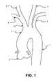
Figure 1 illustrates the vascular anatomy of the aorta and surrounding great vessels.Figure 2 illustrates the common technique incarotid filter 8 insertion forcarotid stenting 10 as delivered via femoral artery over aguidewire 9.Figure 3 illustrates the aortic vasculature where sheaths could be placed by the interventional cardiologist. The right femoral 11 being the most common access as the cardiologist works from the right side of the patient which is presented to the physician while on the table. The rightradial artery 12 has been used but due to the small diameter of the vessel is not a common insertion point for the cardiologist.Figure 4 illustrates a radial entry withcommon introducer 13 and guidewire 8 techniques.Figure 5 illustrates theguide catheter 14 being inserted to theintroducer 13 over theguidewire 8 in a radial artery entry where theguide catheter 14 has a preshaped distal section to access the leftcommon carotid 3.Figure 6 illustrates a closer view of theguide catheter 14 andguidewire 8 accessing the left carotid artery where the first filter would be placed.Figure 7 illustrates the deployment of thefirst filter 9 through theguide catheter 14 over aguidewire 8 where thefilter 9 is fully opposed to the left carotid artery.Figure 8 illustrates bothfilters 9 deployed and protecting the carotid arteries utilizing acommon guidewire 8 andcommon guide catheter 14.Figure 9 illustrates adual lumen catheter 29 where eachfilter 9 has asingle guidewire 8. Bothfilters 9 are in a conventional orientation where the flow is in the distal direction or toward the distal tip of theguidewire 8. Independent recovery of thefilters 9 could occur or a common recovery sheath may be used to load both into one sheath.Figure 10 illustrates bothfilters 9 being delivered via subclavian where the left filter is delivered via left subclavian artery with an entry point in the radial artery. Each delivery would include aguidewire 8 and aguide catheter 14 where a pre-shaped curve would allow access into the respective carotid artery.Figure 11 illustrates asingle organization catheter 15 to retain twofilter 9guidewires 8 controlling the potential for entanglement with each wire or other catheters introduced to the body. These catheters would include pigtail catheters used for contrast injections, balloon catheters for dilation or other catheters for delivery of therapeutic agents or implantable devices such as stents or prosthetic heart valves where the catheters are generally larger (18-26 French) in diameter. The catheter would have two distal exit ports to allow each filter to exit at the respective ostia. A distal section would extend beyond the brachiocephalic trunk allowing for a smooth shape to the catheter and ensure it is close to the outer radius of the arch.Figure 12 illustrates adual lumen catheter 16 with an active curving mechanism to steer each lumen to the respected carotid artery. The deflection will allow for active steering of each distal section to account for any differences in anatomy from patient to patient. Similar to electrophysiology catheters adeflection wire 18 could be tensioned to provide a bias or curve to tip. The delivery of each filter would be in a conventional orientation where the blood flow would be in the distal direction and toward the tip of the guidewire. External to the body would be ahandle mechanism 17 providing an actuation force to the distal portion of the catheter. This actuation could be arotational knob 19 translating a rotation movement to a screw mechanism providing a tension to a wire connected to the catheter tip. Other methods could include an electrical signal to drive a motion or hydraulic actuation to translate a force.Figure 13 illustrates afilter 9 delivered over theguidwire 8 from the carotid artery in a retrograde approach just short of the aortic arch. Once the procedure is completed the filter can be snared with aconventional snare 20 to remove it from the body. This will allow for a very small (0.03 inch) entry port in the neck to introduce the device and alarger recovery sheath 21 in the groin where other devices are introduced.Figure 14 illustrates a set of filters in the carotid arteries delivered and ready for additional procedures to occur under filtered protection. During a percutaneous heart valve delivery there maybe multiple catheters in the aortic arch consuming much of the available area. Shown here is apigtail catheter 22 and adelivery catheter 24 for apercutaneous heart valve 23 all within the aortic arch. Thefilters 9 are clear of the aortic space and will not interfere with delivery or withdrawal of these catheters.Figure 15 illustrates another delivery pathway for the placement in the carotid or brachiocephalic trunk. Delivery includes aguidewire 8 introduced via carotid artery or subclavian artery just short of the aortic arch leaving the arch free from interference while delivering other catheters to the heart. Thesefilters 9 can be retrieved either through the groin or recovered back through the entry point in the carotid or subclavian artery.Figure 16 illustrates a conventional entry to the carotid artery where the sheath is placed in a retrograde manner. Asheath 13 is placed into the carotid artery where access may be gained to the vasculature either antigrade or retrograde depending upon the desired placement of the device.Figure 17 illustrates an example of a common filter design where theguidewire 8 passes through the central portion of thefilter 27. A memory material such as Nitinol is used to expand the filter material to the vessel wall.Figure 18 illustrates other examples of filters where aloop style 25 has the guidewire passing along the side of the device and functions like a wind-sox when deployed in the vessel. The other example is a framed filter where when expanded the filter material is opposed to the vessel wall and theguidewire 8 passes through the central portion of the device.- Before standard intervention would occur by a cardiologist a filter would be placed into the carotid arteries to protect the circulation to the brain where emboli could induce a stroke and leave the patient debilitated. Placement of these filters to the patient's carotid circulation would be most convenient if it occurred without obstruction of the aorta where other catheters would be passed and preferably on the patient's right side as it is common practice for the doctor to steer the catheters from this side of the table. Standard practice is to gain access in the right femoral artery where a sheath would be placed to introduce catheters, guidewires and other device delivery means. This would leave the left femoral artery open but often it too is used for other diagnostic catheters and it is less convenient to work across the patient's body. Other access sites would include carotid entry but the neck area is often again inconvenient to operate from and generally too far from the other wires and catheters. The final entry point would be a radial or an arm entry where a sheath would be placed into the radial artery for access to the subclavian artery and more distally the aorta and the carotid arteries. This approach would allow the doctor to access the patient's right arm placing a sheath into the radial artery and delivering catheters, guidewires and sheaths to the carotid arteries. After a 5 French sheath placement a guide catheter would be placed into the radial artery and advanced to the brachiocephalic trunk where the right carotid artery meets the subclavian. From here a curve in the guide catheter would allow a 180 turn to occur accessing from the brachiocephalic trunk into the aortic arch and back up the left carotid anery which is commonly found one centimeter down the aortic arch. Once the guide catheter is place a filter may be advanced into the left carotid artery and deployed leaving this vessel protected from emboli. The guide catheter could be moved proximally to leave this vasculature and back into the brachiocephalic trunk artery where a coaxial filter could now be placed protecting this carotid artery. The connection between the two filters is a common axial link where the distal or left carotid filter would be attached to a 0.014 inch guidewire as normally constructed and the more proximal filter would utilize a tubular member such as a polymer or Nitinol hypo tube. The distal filter may need to be gently engaged to the vessel wall to allow the connection guidewire to be tensioned removing any slack or loop within the aortic arch. This may be possible with engagement barbs restricting proximal motion of the device in the vessel when deployed. Other means may be a stronger force in the memory metal loop to keep the device opposed to the wall. Now the circulation to the brain is protected and the aortic arch is clear from obstruction the normal procedure can occur. Examples of these procedures include but are not limited to:
- Coronary stenting
- Aortic valve replacement via catheterization
- Aortic or mitral valve replacement via transapical
- Aortic balloon valvuloplasty
- Mitral valvuloplasty
- Mitral valve replacement via catheterization
- Diagnostic catheterization
- Surgical valve replacement (aortic or mitral)
- Surgical valve repair (aortic or mitral)
- Annuloplasty ring placement
- Atrial fibrillation catheterization
- PFO closure (surgical or catheter based)
- Left atrial appendage closure (catheter or surgical)
- Once the procedure has been completed the filters may be removed immediately or left in place if an antitrombotic coating is added or the patient remains on blood thinning agents to limit clot from forming on the filters. It may be advantageous to leave the filters in for a period of twenty four hours as the patient begins to recover. When removal is necessary the goal is to not dislodge any trapped emboli within the filter. Conventionally this is accomplished by pulling the filter into a larger recovery sheath to first close the open end of the filter and draw the remaining portion safely back into the recovery catheter. With the filters being opposed in direction it may be advantageous to move the distal filter into the proximal filter and recover them both together in a nested orientation.
Claims (12)
- A blood filtering system to prevent foreign material from traveling into a subject's carotid circulation, comprising:a delivery device (16) comprising a first lumen; anda first expandable filter disposed with the first lumen in a collapsed delivery configuration;characterized in that:the delivery device further comprises a second lumen; andthe system further comprises:a second expandable filter disposed with the second lumen in a collapsed delivery configuration;an actuation member (18) configured to controllably bend the first lumen relative to the second lumen to allow the first filter to be deployed in a left carotid artery; anda device (17) external to the subject to actuate the actuation member.
- The system of claim 1 further comprising a second actuation member configured to controllably bend the second lumen relative to the first lumen.
- The system of claim 1, wherein the second lumen comprises a curve to allow easy access to the right carotid artery.
- The system of any one of the preceding claims, further comprising a pull wire, wherein tension applied to the pull wire generates a compressive force to bend the second lumen.
- The system of claim 1, wherein the second lumen comprises a pre-shaped curve.
- The system of claim 5, wherein the pre-shaped curve can be retained in a straighter manner to allow for delivery and released to express a curved delivery shape when at the bifurcation of the subclavian and the carotid artery.
- The system of any one of the preceding claims, wherein a length of the first lumen is longer than a length of the second lumen.
- The system of any one of the preceding claims, wherein the first and second lumens are staggered in length to reach each ostium.
- The system of any one of the preceding claims, wherein the first filter is mounted on a guidewire.
- The system of any one of the preceding claims, wherein the first filter is mounted on a hypotube.
- The system of any one of the preceding claims, wherein the second filter is mounted on a guidewire.
- The system of any one of the preceding claims, wherein the second filter is mounted on a hypotube.
Applications Claiming Priority (2)
| Application Number | Priority Date | Filing Date | Title |
|---|---|---|---|
| US14514909P | 2009-01-16 | 2009-01-16 | |
| PCT/US2010/021417WO2010083527A2 (en) | 2009-01-16 | 2010-01-19 | Intravascular blood filter |
Publications (3)
| Publication Number | Publication Date |
|---|---|
| EP2387427A2 EP2387427A2 (en) | 2011-11-23 |
| EP2387427A4 EP2387427A4 (en) | 2013-01-02 |
| EP2387427B1true EP2387427B1 (en) | 2014-08-27 |
Family
ID=42337545
Family Applications (1)
| Application Number | Title | Priority Date | Filing Date |
|---|---|---|---|
| EP10732227.3AActiveEP2387427B1 (en) | 2009-01-16 | 2010-01-19 | Intravascular blood filter |
Country Status (4)
| Country | Link |
|---|---|
| US (6) | US8372108B2 (en) |
| EP (1) | EP2387427B1 (en) |
| ES (1) | ES2516066T3 (en) |
| WO (1) | WO2010083527A2 (en) |
Cited By (10)
| Publication number | Priority date | Publication date | Assignee | Title |
|---|---|---|---|---|
| US9055997B2 (en) | 2010-12-30 | 2015-06-16 | Claret Medical, Inc. | Method of isolating the cerebral circulation during a cardiac procedure |
| US9326843B2 (en) | 2009-01-16 | 2016-05-03 | Claret Medical, Inc. | Intravascular blood filters and methods of use |
| US9566144B2 (en) | 2015-04-22 | 2017-02-14 | Claret Medical, Inc. | Vascular filters, deflectors, and methods |
| US10130458B2 (en) | 2009-07-27 | 2018-11-20 | Claret Medical, Inc. | Dual endovascular filter and methods of use |
| US11154390B2 (en) | 2017-12-19 | 2021-10-26 | Claret Medical, Inc. | Systems for protection of the cerebral vasculature during a cardiac procedure |
| US11191630B2 (en) | 2017-10-27 | 2021-12-07 | Claret Medical, Inc. | Systems and methods for protecting the cerebral vasculature |
| US11351023B2 (en) | 2018-08-21 | 2022-06-07 | Claret Medical, Inc. | Systems and methods for protecting the cerebral vasculature |
| US11364106B2 (en) | 2009-01-16 | 2022-06-21 | Boston Scientific Scimed, Inc. | Intravascular blood filter |
| US11439491B2 (en) | 2018-04-26 | 2022-09-13 | Claret Medical, Inc. | Systems and methods for protecting the cerebral vasculature |
| US12150851B2 (en) | 2010-12-30 | 2024-11-26 | Claret Medical, Inc. | Method of isolating the cerebral circulation during a cardiac procedure |
Families Citing this family (48)
| Publication number | Priority date | Publication date | Assignee | Title |
|---|---|---|---|---|
| US9510930B2 (en) | 2008-10-22 | 2016-12-06 | Contego Medical, Llc | Angioplasty device with embolic filter |
| US9707071B2 (en) | 2004-11-24 | 2017-07-18 | Contego Medical Llc | Percutaneous transluminal angioplasty device with integral embolic filter |
| JP5762955B2 (en) | 2008-06-23 | 2015-08-12 | ルーメン・バイオメディカル・インコーポレイテッドLumen Biomedical, Inc. | Embolization prevention during percutaneous heart valve replacement and similar procedures |
| US20170202657A1 (en) | 2009-01-16 | 2017-07-20 | Claret Medical, Inc. | Intravascular blood filters and methods of use |
| US9636205B2 (en) | 2009-01-16 | 2017-05-02 | Claret Medical, Inc. | Intravascular blood filters and methods of use |
| US8518073B2 (en)* | 2009-01-29 | 2013-08-27 | Claret Medical, Inc. | Illuminated intravascular blood filter |
| US20120203265A1 (en)* | 2010-10-14 | 2012-08-09 | Heuser Richard R | Embolism protection device |
| WO2013063124A1 (en) | 2011-10-25 | 2013-05-02 | Boston Scientific Scimed, Inc. | Embolic debris deflector |
| US8968354B2 (en) | 2011-10-26 | 2015-03-03 | Boston Scientific Scimed, Inc. | Extended protection embolic filter |
| US10426501B2 (en) | 2012-01-13 | 2019-10-01 | Crux Biomedical, Inc. | Retrieval snare device and method |
| US10548706B2 (en) | 2012-01-13 | 2020-02-04 | Volcano Corporation | Retrieval snare device and method |
| EP2805515B1 (en) | 2012-01-17 | 2022-10-05 | Lumen Biomedical, Inc. | Aortic arch filtration system for carotid artery protection |
| US10213187B1 (en) | 2012-01-25 | 2019-02-26 | Mubin I. Syed | Method and apparatus for percutaneous superficial temporal artery access for carotid artery stenting |
| US10213288B2 (en) | 2012-03-06 | 2019-02-26 | Crux Biomedical, Inc. | Distal protection filter |
| US9861464B2 (en) | 2012-04-13 | 2018-01-09 | Regents Of The University Of Minnesota | Cardio-embolic stroke prevention |
| US9358022B2 (en) | 2012-05-21 | 2016-06-07 | Noha, Llc | Clot removal device and method of using same |
| WO2014081947A1 (en) | 2012-11-21 | 2014-05-30 | Syed Mubin I | System for the intravascular placement of a medical device |
| US9186238B2 (en) | 2013-01-29 | 2015-11-17 | St. Jude Medical, Cardiology Division, Inc. | Aortic great vessel protection |
| US9968434B2 (en)* | 2013-06-10 | 2018-05-15 | Subbarao V. Myla | Methods and devices for embolic protection |
| US10350098B2 (en) | 2013-12-20 | 2019-07-16 | Volcano Corporation | Devices and methods for controlled endoluminal filter deployment |
| AU2016209053B2 (en) | 2015-01-23 | 2020-04-16 | Contego Medical, Inc. | Interventional device having an integrated embolic filter and associated methods |
| US9636244B2 (en) | 2015-04-09 | 2017-05-02 | Mubin I. Syed | Apparatus and method for proximal to distal stent deployment |
| EP3288492B1 (en) | 2015-04-30 | 2024-10-16 | EmStop Inc. | System for implanting a prosthetic aortic valve and an embolic material blocking catheter |
| EP3315091A4 (en) | 2015-06-29 | 2019-02-20 | Access Point Technologies, Inc. | Emboli capture device |
| US10492936B2 (en) | 2015-10-30 | 2019-12-03 | Ram Medical Innovations, Llc | Apparatus and method for improved access of procedural catheter in tortuous vessels |
| US11020256B2 (en) | 2015-10-30 | 2021-06-01 | Ram Medical Innovations, Inc. | Bifurcated “Y” anchor support for coronary interventions |
| US10327929B2 (en) | 2015-10-30 | 2019-06-25 | Ram Medical Innovations, Llc | Apparatus and method for stabilization of procedural catheter in tortuous vessels |
| US10779976B2 (en) | 2015-10-30 | 2020-09-22 | Ram Medical Innovations, Llc | Apparatus and method for stabilization of procedural catheter in tortuous vessels |
| US9980838B2 (en)* | 2015-10-30 | 2018-05-29 | Ram Medical Innovations Llc | Apparatus and method for a bifurcated catheter for use in hostile aortic arches |
| US10173031B2 (en) | 2016-06-20 | 2019-01-08 | Mubin I. Syed | Interchangeable flush/selective catheter |
| US10456252B2 (en) | 2016-08-31 | 2019-10-29 | Medtronic Vascular, Inc. | Transcatheter guidewire delivery systems, catheter assemblies for guidewire delivery, and methods for percutaneous guidewire delivery across heart valves |
| US11337790B2 (en) | 2017-02-22 | 2022-05-24 | Boston Scientific Scimed, Inc. | Systems and methods for protecting the cerebral vasculature |
| EP3585305B1 (en) | 2017-02-23 | 2025-07-30 | Boston Scientific Scimed, Inc. | Medical drain device |
| US11134967B2 (en)* | 2017-12-13 | 2021-10-05 | Eric Raul GUERRA | Thrombectomy catheter and methods of use |
| US11229451B2 (en) | 2017-12-13 | 2022-01-25 | Eric Raul GUERRA | Thrombectomy catheter and methods of use |
| CN111902105B (en) | 2017-12-28 | 2023-08-01 | 艾姆斯托普股份有限公司 | Embolic material capture catheter and related devices and methods |
| US11007075B2 (en) | 2018-02-18 | 2021-05-18 | Ram Medical Innovations, Inc. | Vascular access devices and methods for lower limb interventions |
| US11389284B2 (en) | 2018-09-28 | 2022-07-19 | Boston Scientific Scimed, Inc. | Embolic protection devices |
| US10828038B2 (en) | 2018-10-05 | 2020-11-10 | Lakshmikumar Pillai, MD | Carotid artery embolic protection method using percutaneous transjugular carotid flow reversal |
| WO2020122978A1 (en)* | 2018-12-15 | 2020-06-18 | Guerra Eric Raul | Thrombectomy catheter and methods of use |
| US11426173B2 (en) | 2019-01-04 | 2022-08-30 | Lakshmikumar Pillai | Devices and methods using percutaneous transjugular carotid flow reversal |
| EP3718505A1 (en) | 2019-04-05 | 2020-10-07 | Aorticlab Sarl | Transcatheter anti embolic filter for arterial and venous vessels |
| US11051928B2 (en) | 2019-04-11 | 2021-07-06 | Neuravi Limited | Floating carotid filter |
| US12042152B2 (en) | 2019-08-21 | 2024-07-23 | Lakshmikumar Pillai | Systems and methods for retrograde perfusion and clearance of emboli |
| US10835258B1 (en) | 2019-08-21 | 2020-11-17 | Lakshmikumar Pillai | Systems and methods for retrograde perfusion and clearance of emboli |
| IT202100006239A1 (en) | 2021-03-16 | 2022-09-16 | Violatech Srl | EMBOLIC PROTECTIVE DEVICE |
| CN114569284B (en)* | 2022-03-29 | 2024-03-15 | 上海以心医疗器械有限公司 | Brain protection device |
| CN114788746A (en)* | 2022-05-27 | 2022-07-26 | 首都医科大学附属北京安贞医院 | Far-end filter brain protection device for cardiac surgery |
Family Cites Families (237)
| Publication number | Priority date | Publication date | Assignee | Title |
|---|---|---|---|---|
| US3472230A (en)* | 1966-12-19 | 1969-10-14 | Fogarty T J | Umbrella catheter |
| US4630609A (en) | 1981-05-14 | 1986-12-23 | Thomas J. Fogarty | Dilatation catheter method and apparatus |
| DK151404C (en)* | 1984-05-23 | 1988-07-18 | Cook Europ Aps William | FULLY FILTER FOR IMPLANTATION IN A PATIENT'S BLOOD |
| US4706671A (en)* | 1985-05-02 | 1987-11-17 | Weinrib Harry P | Catheter with coiled tip |
| US4650466A (en)* | 1985-11-01 | 1987-03-17 | Angiobrade Partners | Angioplasty device |
| US4723549A (en)* | 1986-09-18 | 1988-02-09 | Wholey Mark H | Method and apparatus for dilating blood vessels |
| US4873978A (en)* | 1987-12-04 | 1989-10-17 | Robert Ginsburg | Device and method for emboli retrieval |
| US5254088A (en) | 1990-02-02 | 1993-10-19 | Ep Technologies, Inc. | Catheter steering mechanism |
| ATE128405T1 (en) | 1990-02-20 | 1995-10-15 | Procter & Gamble | OPEN CAPILLARY CHANNELS STRUCTURE, METHOD FOR MAKING SAME AND EXTRUSION NOZZLE FOR USE THEREIN. |
| US5108419A (en)* | 1990-08-16 | 1992-04-28 | Evi Corporation | Endovascular filter and method for use thereof |
| US5348545A (en) | 1990-08-21 | 1994-09-20 | Advanced Cardiovascular Systems, Inc. | Guiding catheter for the right coronary artery |
| US5329923A (en) | 1991-02-15 | 1994-07-19 | Lundquist Ingemar H | Torquable catheter |
| US5304131A (en) | 1991-07-15 | 1994-04-19 | Paskar Larry D | Catheter |
| US5766151A (en)* | 1991-07-16 | 1998-06-16 | Heartport, Inc. | Endovascular system for arresting the heart |
| US5192286A (en)* | 1991-07-26 | 1993-03-09 | Regents Of The University Of California | Method and device for retrieving materials from body lumens |
| WO1993013704A1 (en) | 1992-01-09 | 1993-07-22 | Endomedix Corporation | Bi-directional miniscope |
| EP0746236B1 (en) | 1993-10-01 | 2003-08-20 | Boston Scientific Corporation | Improved vena cava filter |
| ES2340142T3 (en)* | 1994-07-08 | 2010-05-31 | Ev3 Inc. | SYSTEM TO CARRY OUT AN INTRAVASCULAR PROCEDURE. |
| US5624430A (en) | 1994-11-28 | 1997-04-29 | Eton; Darwin | Magnetic device to assist transcorporeal guidewire placement |
| US5613980A (en)* | 1994-12-22 | 1997-03-25 | Chauhan; Tusharsindhu C. | Bifurcated catheter system and method |
| US5680873A (en) | 1995-03-02 | 1997-10-28 | Scimed Life Systems, Inc. | Braidless guide catheter |
| US5833650A (en) | 1995-06-05 | 1998-11-10 | Percusurge, Inc. | Catheter apparatus and method for treating occluded vessels |
| US5707389A (en)* | 1995-06-07 | 1998-01-13 | Baxter International Inc. | Side branch occlusion catheter device having integrated endoscope for performing endoscopically visualized occlusion of the side branches of an anatomical passageway |
| US6264663B1 (en)* | 1995-10-06 | 2001-07-24 | Metamorphic Surgical Devices, Llc | Device for removing solid objects from body canals, cavities and organs including an invertable basket |
| US5779716A (en)* | 1995-10-06 | 1998-07-14 | Metamorphic Surgical Devices, Inc. | Device for removing solid objects from body canals, cavities and organs |
| US5989281A (en)* | 1995-11-07 | 1999-11-23 | Embol-X, Inc. | Cannula with associated filter and methods of use during cardiac surgery |
| US5769816A (en)* | 1995-11-07 | 1998-06-23 | Embol-X, Inc. | Cannula with associated filter |
| US6096053A (en)* | 1996-05-03 | 2000-08-01 | Scimed Life Systems, Inc. | Medical retrieval basket |
| US5935139A (en)* | 1996-05-03 | 1999-08-10 | Boston Scientific Corporation | System for immobilizing or manipulating an object in a tract |
| US6048331A (en) | 1996-05-14 | 2000-04-11 | Embol-X, Inc. | Cardioplegia occluder |
| US20050245894A1 (en) | 1996-05-20 | 2005-11-03 | Medtronic Vascular, Inc. | Methods and apparatuses for drug delivery to an intravascular occlusion |
| US6068623A (en)* | 1997-03-06 | 2000-05-30 | Percusurge, Inc. | Hollow medical wires and methods of constructing same |
| US5910364A (en) | 1996-07-10 | 1999-06-08 | Asahi Intecc Co., Ltd. | Guide wire and a method of making the same |
| US5662671A (en)* | 1996-07-17 | 1997-09-02 | Embol-X, Inc. | Atherectomy device having trapping and excising means for removal of plaque from the aorta and other arteries |
| US7094249B1 (en)* | 1997-03-06 | 2006-08-22 | Boston Scientific Scimed, Inc. | Distal protection device and method |
| US6152946A (en)* | 1998-03-05 | 2000-11-28 | Scimed Life Systems, Inc. | Distal protection device and method |
| US5814064A (en) | 1997-03-06 | 1998-09-29 | Scimed Life Systems, Inc. | Distal protection device |
| EP0934092A4 (en) | 1997-03-06 | 2008-03-26 | Boston Scient Scimed Inc | DEVICE AND METHOD FOR DISTAL PROTECTION |
| US5827324A (en)* | 1997-03-06 | 1998-10-27 | Scimed Life Systems, Inc. | Distal protection device |
| US20020026145A1 (en) | 1997-03-06 | 2002-02-28 | Bagaoisan Celso J. | Method and apparatus for emboli containment |
| US6676682B1 (en)* | 1997-05-08 | 2004-01-13 | Scimed Life Systems, Inc. | Percutaneous catheter and guidewire having filter and medical device deployment capabilities |
| US5911734A (en)* | 1997-05-08 | 1999-06-15 | Embol-X, Inc. | Percutaneous catheter and guidewire having filter and medical device deployment capabilities |
| US6258120B1 (en) | 1997-12-23 | 2001-07-10 | Embol-X, Inc. | Implantable cerebral protection device and methods of use |
| US5848964A (en) | 1997-06-06 | 1998-12-15 | Samuels; Shaun Lawrence Wilkie | Temporary inflatable filter device and method of use |
| US6245088B1 (en)* | 1997-07-07 | 2001-06-12 | Samuel R. Lowery | Retrievable umbrella sieve and method of use |
| US7569066B2 (en) | 1997-07-10 | 2009-08-04 | Boston Scientific Scimed, Inc. | Methods and devices for the treatment of aneurysms |
| US6063070A (en) | 1997-08-05 | 2000-05-16 | Target Therapeutics, Inc. | Detachable aneurysm neck bridge (II) |
| US5897529A (en) | 1997-09-05 | 1999-04-27 | Cordis Webster, Inc. | Steerable deflectable catheter having improved flexibility |
| US6361545B1 (en) | 1997-09-26 | 2002-03-26 | Cardeon Corporation | Perfusion filter catheter |
| US6066149A (en) | 1997-09-30 | 2000-05-23 | Target Therapeutics, Inc. | Mechanical clot treatment device with distal filter |
| US6099534A (en) | 1997-10-01 | 2000-08-08 | Scimed Life Systems, Inc. | Releasable basket |
| EP1028670B1 (en)* | 1997-11-07 | 2008-01-02 | Salviac Limited | An embolic protection device |
| US6530902B1 (en) | 1998-01-23 | 2003-03-11 | Medtronic, Inc. | Cannula placement system |
| US6159178A (en) | 1998-01-23 | 2000-12-12 | Heartport, Inc. | Methods and devices for occluding the ascending aorta and maintaining circulation of oxygenated blood in the patient when the patient's heart is arrested |
| US6423032B2 (en)* | 1998-03-13 | 2002-07-23 | Arteria Medical Science, Inc. | Apparatus and methods for reducing embolization during treatment of carotid artery disease |
| US6045547A (en) | 1998-06-15 | 2000-04-04 | Scimed Life Systems, Inc. | Semi-continuous co-extruded catheter shaft |
| IL124958A0 (en) | 1998-06-16 | 1999-01-26 | Yodfat Ofer | Implantable blood filtering device |
| US6336116B1 (en) | 1998-08-06 | 2002-01-01 | Ryan Brown | Search and index hosting system |
| US6726651B1 (en) | 1999-08-04 | 2004-04-27 | Cardeon Corporation | Method and apparatus for differentially perfusing a patient during cardiopulmonary bypass |
| US6440120B1 (en) | 1998-09-02 | 2002-08-27 | Embol-X, Inc. | Bendable shape-retaining cannula |
| US6342062B1 (en) | 1998-09-24 | 2002-01-29 | Scimed Life Systems, Inc. | Retrieval devices for vena cava filter |
| US6051014A (en) | 1998-10-13 | 2000-04-18 | Embol-X, Inc. | Percutaneous filtration catheter for valve repair surgery and methods of use |
| US6080140A (en) | 1998-11-04 | 2000-06-27 | Iowa-India Investments Company, Ltd. | Integral cerebro-vascular access system |
| US6083239A (en)* | 1998-11-24 | 2000-07-04 | Embol-X, Inc. | Compliant framework and methods of use |
| US6161547A (en)* | 1999-01-15 | 2000-12-19 | Coaxia, Inc. | Medical device for flow augmentation in patients with occlusive cerebrovascular disease and methods of use |
| US6896690B1 (en) | 2000-01-27 | 2005-05-24 | Viacor, Inc. | Cardiac valve procedure methods and devices |
| US20020138094A1 (en) | 1999-02-12 | 2002-09-26 | Thomas Borillo | Vascular filter system |
| US6991641B2 (en) | 1999-02-12 | 2006-01-31 | Cordis Corporation | Low profile vascular filter system |
| US6146396A (en) | 1999-03-05 | 2000-11-14 | Board Of Regents, The University Of Texas System | Declotting method and apparatus |
| US6277138B1 (en) | 1999-08-17 | 2001-08-21 | Scion Cardio-Vascular, Inc. | Filter for embolic material mounted on expandable frame |
| US20040044350A1 (en) | 1999-04-09 | 2004-03-04 | Evalve, Inc. | Steerable access sheath and methods of use |
| US6267776B1 (en) | 1999-05-03 | 2001-07-31 | O'connell Paul T. | Vena cava filter and method for treating pulmonary embolism |
| GB2365356A (en)* | 1999-05-07 | 2002-02-20 | Salviac Ltd | An embolic protection device |
| US6964672B2 (en) | 1999-05-07 | 2005-11-15 | Salviac Limited | Support frame for an embolic protection device |
| US7637905B2 (en) | 2003-01-15 | 2009-12-29 | Usgi Medical, Inc. | Endoluminal tool deployment system |
| US6364900B1 (en) | 1999-07-14 | 2002-04-02 | Richard R. Heuser | Embolism prevention device |
| US6371970B1 (en) | 1999-07-30 | 2002-04-16 | Incept Llc | Vascular filter having articulation region and methods of use in the ascending aorta |
| US6589263B1 (en) | 1999-07-30 | 2003-07-08 | Incept Llc | Vascular device having one or more articulation regions and methods of use |
| US6616679B1 (en) | 1999-07-30 | 2003-09-09 | Incept, Llc | Rapid exchange vascular device for emboli and thrombus removal and methods of use |
| JP4439780B2 (en) | 1999-07-30 | 2010-03-24 | インセプト エルエルシー | Vascular device for removal of emboli, thrombus and foreign bodies |
| US7306618B2 (en) | 1999-07-30 | 2007-12-11 | Incept Llc | Vascular device for emboli and thrombi removal and methods of use |
| US6620182B1 (en) | 1999-07-30 | 2003-09-16 | Incept Llc | Vascular filter having articulation region and methods of use in the ascending aorta |
| US6544279B1 (en) | 2000-08-09 | 2003-04-08 | Incept, Llc | Vascular device for emboli, thrombus and foreign body removal and methods of use |
| US20020022858A1 (en) | 1999-07-30 | 2002-02-21 | Demond Jackson F. | Vascular device for emboli removal having suspension strut and methods of use |
| EP1207933B1 (en) | 1999-07-30 | 2011-05-11 | Incept Llc | Vascular filter having articulation region |
| US6179861B1 (en) | 1999-07-30 | 2001-01-30 | Incept Llc | Vascular device having one or more articulation regions and methods of use |
| US6203561B1 (en) | 1999-07-30 | 2001-03-20 | Incept Llc | Integrated vascular device having thrombectomy element and vascular filter and methods of use |
| US6214026B1 (en) | 1999-07-30 | 2001-04-10 | Incept Llc | Delivery system for a vascular device with articulation region |
| US6530939B1 (en) | 1999-07-30 | 2003-03-11 | Incept, Llc | Vascular device having articulation region and methods of use |
| US6142987A (en)* | 1999-08-03 | 2000-11-07 | Scimed Life Systems, Inc. | Guided filter with support wire and methods of use |
| US6346116B1 (en)* | 1999-08-03 | 2002-02-12 | Medtronic Ave, Inc. | Distal protection device |
| US6245087B1 (en) | 1999-08-03 | 2001-06-12 | Embol-X, Inc. | Variable expansion frame system for deploying medical devices and methods of use |
| US6168579B1 (en) | 1999-08-04 | 2001-01-02 | Scimed Life Systems, Inc. | Filter flush system and methods of use |
| WO2001015629A1 (en)* | 1999-08-27 | 2001-03-08 | Microvena Corporation | Slideable vascular filter |
| US6325815B1 (en) | 1999-09-21 | 2001-12-04 | Microvena Corporation | Temporary vascular filter |
| US6171328B1 (en)* | 1999-11-09 | 2001-01-09 | Embol-X, Inc. | Intravascular catheter filter with interlocking petal design and methods of use |
| US6371971B1 (en)* | 1999-11-15 | 2002-04-16 | Scimed Life Systems, Inc. | Guidewire filter and methods of use |
| US7018406B2 (en) | 1999-11-17 | 2006-03-28 | Corevalve Sa | Prosthetic valve for transluminal delivery |
| JP3426174B2 (en) | 1999-12-24 | 2003-07-14 | 朝日インテック株式会社 | Medical guidewire |
| US6290710B1 (en) | 1999-12-29 | 2001-09-18 | Advanced Cardiovascular Systems, Inc. | Embolic protection device |
| US6485502B2 (en)* | 2000-03-10 | 2002-11-26 | T. Anthony Don Michael | Vascular embolism prevention device employing filters |
| US6719717B1 (en) | 2000-03-17 | 2004-04-13 | Advanced Research & Technology Institute, Inc. | Thrombectomy treatment system and method |
| US6837846B2 (en)* | 2000-04-03 | 2005-01-04 | Neo Guide Systems, Inc. | Endoscope having a guide tube |
| US6454799B1 (en) | 2000-04-06 | 2002-09-24 | Edwards Lifesciences Corporation | Minimally-invasive heart valves and methods of use |
| US6824545B2 (en)* | 2000-06-29 | 2004-11-30 | Concentric Medical, Inc. | Systems, methods and devices for removing obstructions from a blood vessel |
| US6740061B1 (en)* | 2000-07-28 | 2004-05-25 | Ev3 Inc. | Distal protection device |
| US6482221B1 (en) | 2000-08-21 | 2002-11-19 | Counter Clockwise, Inc. | Manipulatable delivery catheter for occlusive devices (II) |
| DE10047421C1 (en) | 2000-09-26 | 2003-01-02 | Klaus Sodemann | Method and device for ultrafiltration control in blood treatment methods |
| DE10049812B4 (en) | 2000-10-09 | 2004-06-03 | Universitätsklinikum Freiburg | Device for filtering out macroscopic particles from the bloodstream during local removal of an aortic valve on the human or animal heart |
| WO2002032496A1 (en)* | 2000-10-18 | 2002-04-25 | Nmt Medical, Inc. | Over-the-wire interlock attachment/detachment mechanism |
| US6595983B2 (en) | 2000-12-07 | 2003-07-22 | Jan K. Voda | Guide or diagnostic catheter for right coronary artery |
| US7169165B2 (en)* | 2001-01-16 | 2007-01-30 | Boston Scientific Scimed, Inc. | Rapid exchange sheath for deployment of medical devices and methods of use |
| US6663651B2 (en) | 2001-01-16 | 2003-12-16 | Incept Llc | Systems and methods for vascular filter retrieval |
| US7011094B2 (en) | 2001-03-02 | 2006-03-14 | Emphasys Medical, Inc. | Bronchial flow control devices and methods of use |
| US20040243175A1 (en) | 2001-03-12 | 2004-12-02 | Don Michael T. Anthony | Vascular obstruction removal system and method |
| US7806906B2 (en)* | 2001-03-12 | 2010-10-05 | Don Michael T Anthony | Vascular filter with improved strength and flexibility |
| US7214237B2 (en)* | 2001-03-12 | 2007-05-08 | Don Michael T Anthony | Vascular filter with improved strength and flexibility |
| US6881194B2 (en) | 2001-03-21 | 2005-04-19 | Asahi Intec Co., Ltd. | Wire-stranded medical hollow tube, and a medical guide wire |
| JP3734717B2 (en) | 2001-04-26 | 2006-01-11 | 富士通株式会社 | Image sensor |
| US6830579B2 (en)* | 2001-05-01 | 2004-12-14 | Coaxia, Inc. | Devices and methods for preventing distal embolization using flow reversal and perfusion augmentation within the cerebral vasculature |
| US6997939B2 (en) | 2001-07-02 | 2006-02-14 | Rubicon Medical, Inc. | Methods, systems, and devices for deploying an embolic protection filter |
| US7160255B2 (en)* | 2001-07-12 | 2007-01-09 | Vahid Saadat | Method and device for sensing and mapping temperature profile of a hollow body organ |
| US7169161B2 (en) | 2001-11-06 | 2007-01-30 | Possis Medical, Inc. | Guidewire having occlusive device and repeatably crimpable proximal end |
| EP1455686A2 (en) | 2001-12-21 | 2004-09-15 | Salviac Limited | A support frame for an embolic protection device |
| US6817999B2 (en) | 2002-01-03 | 2004-11-16 | Afx, Inc. | Flexible device for ablation of biological tissue |
| US6958074B2 (en) | 2002-01-07 | 2005-10-25 | Cordis Corporation | Releasable and retrievable vascular filter system |
| US6907298B2 (en) | 2002-01-09 | 2005-06-14 | Medtronic, Inc. | Method and apparatus for imparting curves in implantable elongated medical instruments |
| US20030144686A1 (en)* | 2002-01-30 | 2003-07-31 | Embol-X, Inc. | Distal filtration devices and methods of use during aortic procedures |
| DE60315425T2 (en) | 2002-03-05 | 2008-06-26 | Salviac Ltd. | SYSTEM FOR PROTECTION FROM EMBOLICS |
| US6773448B2 (en)* | 2002-03-08 | 2004-08-10 | Ev3 Inc. | Distal protection devices having controllable wire motion |
| US6887258B2 (en)* | 2002-06-26 | 2005-05-03 | Advanced Cardiovascular Systems, Inc. | Embolic filtering devices for bifurcated vessels |
| US7115134B2 (en)* | 2002-07-22 | 2006-10-03 | Chambers Technology, Llc. | Catheter with flexible tip and shape retention |
| US7303575B2 (en)* | 2002-08-01 | 2007-12-04 | Lumen Biomedical, Inc. | Embolism protection devices |
| AU2003262938A1 (en)* | 2002-08-27 | 2004-03-19 | Amir Belson | Embolic protection device |
| US7174636B2 (en) | 2002-09-04 | 2007-02-13 | Scimed Life Systems, Inc. | Method of making an embolic filter |
| AU2003263454A1 (en)* | 2002-09-19 | 2004-04-08 | Petrus Besselink | Vascular filter with improved strength and flexibility |
| US7313445B2 (en) | 2002-09-26 | 2007-12-25 | Medtronic, Inc. | Medical lead with flexible distal guidewire extension |
| US7493154B2 (en) | 2002-10-23 | 2009-02-17 | Medtronic, Inc. | Methods and apparatus for locating body vessels and occlusions in body vessels |
| US7323001B2 (en)* | 2003-01-30 | 2008-01-29 | Ev3 Inc. | Embolic filters with controlled pore size |
| WO2004071343A2 (en) | 2003-02-11 | 2004-08-26 | Cook, Inc. | Removable vena cava filter |
| US7740644B2 (en) | 2003-02-24 | 2010-06-22 | Boston Scientific Scimed, Inc. | Embolic protection filtering device that can be adapted to be advanced over a guidewire |
| US20060041188A1 (en) | 2003-03-25 | 2006-02-23 | Dirusso Carlo A | Flexible endoscope |
| EP1608295B1 (en) | 2003-03-28 | 2017-05-03 | Covidien LP | Double ended intravascular medical device |
| US7597704B2 (en) | 2003-04-28 | 2009-10-06 | Atritech, Inc. | Left atrial appendage occlusion device with active expansion |
| US6969396B2 (en) | 2003-05-07 | 2005-11-29 | Scimed Life Systems, Inc. | Filter membrane with increased surface area |
| EP1635736A2 (en) | 2003-06-05 | 2006-03-22 | FlowMedica, Inc. | Systems and methods for performing bi-lateral interventions or diagnosis in branched body lumens |
| US7537600B2 (en) | 2003-06-12 | 2009-05-26 | Boston Scientific Scimed, Inc. | Valved embolic protection filter |
| US7722634B2 (en) | 2003-07-03 | 2010-05-25 | Regents Of The University Of Minnesota | Medical device and method of intravenous filtration |
| US7879062B2 (en) | 2003-07-22 | 2011-02-01 | Lumen Biomedical, Inc. | Fiber based embolism protection device |
| US7371248B2 (en)* | 2003-10-14 | 2008-05-13 | Medtronic Vascular, Inc. | Steerable distal protection guidewire and methods of use |
| US8048103B2 (en)* | 2003-11-06 | 2011-11-01 | Boston Scientific Scimed, Inc. | Flattened tip filter wire design |
| US7998104B2 (en) | 2003-11-21 | 2011-08-16 | Silk Road Medical, Inc. | Method and apparatus for treating a carotid artery |
| US7651514B2 (en) | 2003-12-11 | 2010-01-26 | Boston Scientific Scimed, Inc. | Nose rider improvement for filter exchange and methods of use |
| US20050137696A1 (en)* | 2003-12-23 | 2005-06-23 | Sadra Medical | Apparatus and methods for protecting against embolization during endovascular heart valve replacement |
| JP2005185386A (en) | 2003-12-25 | 2005-07-14 | Asahi Intecc Co Ltd | Medical guidewire |
| US7976562B2 (en) | 2004-01-22 | 2011-07-12 | Rex Medical, L.P. | Method of removing a vein filter |
| US7637903B2 (en) | 2004-02-09 | 2009-12-29 | Cryocor, Inc. | Catheter articulation segment with alternating cuts |
| US8092483B2 (en) | 2004-03-06 | 2012-01-10 | Medtronic, Inc. | Steerable device having a corewire within a tube and combination with a functional medical component |
| US7988705B2 (en) | 2004-03-06 | 2011-08-02 | Lumen Biomedical, Inc. | Steerable device having a corewire within a tube and combination with a functional medical component |
| JP3626488B1 (en) | 2004-03-15 | 2005-03-09 | 朝日インテック株式会社 | Medical guidewire |
| US7559925B2 (en)* | 2006-09-15 | 2009-07-14 | Acclarent Inc. | Methods and devices for facilitating visualization in a surgical environment |
| US8409237B2 (en) | 2004-05-27 | 2013-04-02 | Medtronic, Inc. | Emboli filter export system |
| US7544202B2 (en) | 2004-06-25 | 2009-06-09 | Angiodynamics, Inc. | Retrievable blood clot filter |
| WO2006055052A2 (en) | 2004-07-19 | 2006-05-26 | Michael Gertner | Methods and devices for chronic embolic protection |
| US20080154153A1 (en) | 2004-08-25 | 2008-06-26 | Heuser Richard R | Multiple-wire systems and methods for ablation of occlusions within blood vessels |
| JP2008511401A (en) | 2004-08-27 | 2008-04-17 | クック インコーポレイテッド | Apparatus for arranging a plurality of intraluminal medical devices in a body cavity |
| US20060047301A1 (en) | 2004-09-02 | 2006-03-02 | Ogle Matthew F | Emboli removal system with oxygenated flow |
| US7621904B2 (en) | 2004-10-21 | 2009-11-24 | Boston Scientific Scimed, Inc. | Catheter with a pre-shaped distal tip |
| US20060100658A1 (en)* | 2004-11-09 | 2006-05-11 | Hiroyuki Obana | Interventional guiding sheath system and method of use |
| WO2006055967A2 (en) | 2004-11-19 | 2006-05-26 | Lumen Biomedical, Inc. | Extendable device on an aspiration catheter |
| US9510930B2 (en) | 2008-10-22 | 2016-12-06 | Contego Medical, Llc | Angioplasty device with embolic filter |
| US7402151B2 (en)* | 2004-12-17 | 2008-07-22 | Biocardia, Inc. | Steerable guide catheters and methods for their use |
| US9545300B2 (en) | 2004-12-22 | 2017-01-17 | W. L. Gore & Associates, Inc. | Filament-wound implantable devices |
| US20060161241A1 (en)* | 2005-01-14 | 2006-07-20 | Denise Barbut | Methods and devices for treating aortic atheroma |
| GB0501346D0 (en)* | 2005-01-21 | 2005-03-02 | Oxford Instr Molecular Biotool | Method of carrying out dynamic nuclear polarization |
| US20060259066A1 (en) | 2005-04-28 | 2006-11-16 | Euteneuer Charles L | Bifurcated artery filter system |
| US7780723B2 (en)* | 2005-06-13 | 2010-08-24 | Edwards Lifesciences Corporation | Heart valve delivery system |
| US20080172066A9 (en) | 2005-07-29 | 2008-07-17 | Galdonik Jason A | Embolectomy procedures with a device comprising a polymer and devices with polymer matrices and supports |
| US8021351B2 (en) | 2005-08-18 | 2011-09-20 | Medtronic Vascular, Inc. | Tracking aspiration catheter |
| US8632562B2 (en) | 2005-10-03 | 2014-01-21 | Cook Medical Technologies Llc | Embolic protection device |
| US7736346B2 (en) | 2005-10-18 | 2010-06-15 | Biocardia, Inc. | Bio-interventional therapeutic treatments for cardiovascular diseases |
| DE102005059670A1 (en)* | 2005-12-12 | 2007-06-14 | Phenox Gmbh | Device for removing thrombi from blood vessels |
| US7374567B2 (en) | 2006-01-25 | 2008-05-20 | Heuser Richard R | Catheter system for connecting adjacent blood vessels |
| US20070208302A1 (en) | 2006-01-26 | 2007-09-06 | Webster Mark W | Deflection control catheters, support catheters and methods of use |
| EP3075332B1 (en) | 2006-02-13 | 2018-05-16 | RetroVascular, inc. | Recanalizing occluded vessels using controlled antegrade and retrograde tracking |
| US20070225750A1 (en)* | 2006-03-10 | 2007-09-27 | Brooke Ren | Embolic protection systems |
| US7846175B2 (en)* | 2006-04-03 | 2010-12-07 | Medrad, Inc. | Guidewire and collapsable filter system |
| US8092470B2 (en) | 2006-06-08 | 2012-01-10 | Olympus Medical Systems Corp. | Calculus crushing apparatus and medical procedure using endoscope |
| US20080234722A1 (en)* | 2006-06-14 | 2008-09-25 | Possis Medical, Inc. | Inferior vena cava filter on guidewire |
| US8057530B2 (en)* | 2006-06-30 | 2011-11-15 | Tyco Healthcare Group Lp | Medical devices with amorphous metals, and methods therefor |
| US9480548B2 (en)* | 2006-09-11 | 2016-11-01 | Edwards Lifesciences Ag | Embolic protection device and method of use |
| US20100179583A1 (en)* | 2006-09-11 | 2010-07-15 | Carpenter Judith T | Methods of deploying and retrieving an embolic diversion device |
| US20100179584A1 (en)* | 2006-09-11 | 2010-07-15 | Carpenter Judith T | Methods of diverting embolic debris away from the cerebral circulation |
| US20100324589A1 (en) | 2006-09-11 | 2010-12-23 | Carpenter Judith T | Embolic deflection device |
| US8460335B2 (en)* | 2006-09-11 | 2013-06-11 | Embrella Cardiovascular, Inc. | Method of deflecting emboli from the cerebral circulation |
| US9339367B2 (en)* | 2006-09-11 | 2016-05-17 | Edwards Lifesciences Ag | Embolic deflection device |
| US20100179647A1 (en)* | 2006-09-11 | 2010-07-15 | Carpenter Judith T | Methods of reducing embolism to cerebral circulation as a consequence of an index cardiac procedure |
| US9107734B2 (en) | 2006-11-29 | 2015-08-18 | Emboline, Inc. | Embolic protection device |
| US20080147013A1 (en)* | 2006-12-18 | 2008-06-19 | Breton Thomas G | Catheter shape-retaining cover |
| US8333783B2 (en) | 2007-02-16 | 2012-12-18 | Reverse Medical Corporation | Occlusion device and method of use |
| CA2673213A1 (en)* | 2007-03-20 | 2008-09-25 | Minvasys | Apparatus and methods for stent delivery with embolic protection |
| US7717624B2 (en)* | 2007-04-17 | 2010-05-18 | Medeikon Corporation | Connectors for multi fiber optical probes |
| JP5362708B2 (en) | 2007-05-31 | 2013-12-11 | ボストン サイエンティフィック リミテッド | Flexible endoscope |
| EP2497520B1 (en) | 2007-07-18 | 2022-04-13 | Silk Road Medical, Inc. | Systems for establishing retrograde carotid arterial blood flow |
| WO2009032834A1 (en) | 2007-09-07 | 2009-03-12 | Crusader Medical Llc | Percutaneous permanent retrievable vascular filter |
| WO2009062264A1 (en)* | 2007-11-15 | 2009-05-22 | Endogad Research Pty Limited | Hybrid intraluminal device |
| CA2713341C (en)* | 2008-02-05 | 2016-09-27 | Cvdevices, Llc | Steering engagement catheter devices, systems, and methods |
| US8858609B2 (en)* | 2008-02-07 | 2014-10-14 | Intuitive Surgical Operations, Inc. | Stent delivery under direct visualization |
| AU2009232400B2 (en)* | 2008-04-03 | 2013-09-12 | Cook Medical Technologies Llc | Self cleaning devices, systems and methods of use |
| US8096985B2 (en) | 2008-05-07 | 2012-01-17 | Guided Delivery Systems Inc. | Deflectable guide |
| US9061119B2 (en)* | 2008-05-09 | 2015-06-23 | Edwards Lifesciences Corporation | Low profile delivery system for transcatheter heart valve |
| JP5762955B2 (en) | 2008-06-23 | 2015-08-12 | ルーメン・バイオメディカル・インコーポレイテッドLumen Biomedical, Inc. | Embolization prevention during percutaneous heart valve replacement and similar procedures |
| US9101735B2 (en)* | 2008-07-07 | 2015-08-11 | Intuitive Surgical Operations, Inc. | Catheter control systems |
| US8070694B2 (en) | 2008-07-14 | 2011-12-06 | Medtronic Vascular, Inc. | Fiber based medical devices and aspiration catheters |
| US8574245B2 (en) | 2008-08-13 | 2013-11-05 | Silk Road Medical, Inc. | Suture delivery device |
| CA2749385C (en) | 2009-01-09 | 2018-04-17 | Embrella Cardiovascular, Inc. | Embolic deflection device and method of use |
| US9326843B2 (en) | 2009-01-16 | 2016-05-03 | Claret Medical, Inc. | Intravascular blood filters and methods of use |
| US9636205B2 (en) | 2009-01-16 | 2017-05-02 | Claret Medical, Inc. | Intravascular blood filters and methods of use |
| EP2387427B1 (en) | 2009-01-16 | 2014-08-27 | Claret Medical, Inc. | Intravascular blood filter |
| US20170202657A1 (en) | 2009-01-16 | 2017-07-20 | Claret Medical, Inc. | Intravascular blood filters and methods of use |
| US8518073B2 (en) | 2009-01-29 | 2013-08-27 | Claret Medical, Inc. | Illuminated intravascular blood filter |
| US20100228280A1 (en) | 2009-03-09 | 2010-09-09 | Adam Groothuis | Methods and devices for treatment of lumenal systems |
| US8974489B2 (en) | 2009-07-27 | 2015-03-10 | Claret Medical, Inc. | Dual endovascular filter and methods of use |
| US20120046730A1 (en) | 2010-04-14 | 2012-02-23 | Abbott Vascular | Methods of treating a condition of a vessel in a patient |
| US20120095500A1 (en) | 2010-10-14 | 2012-04-19 | Heuser Richard R | Concentric wire embolism protection device |
| US20120203265A1 (en) | 2010-10-14 | 2012-08-09 | Heuser Richard R | Embolism protection device |
| US9492264B2 (en) | 2010-12-30 | 2016-11-15 | Claret Medical, Inc. | Embolic protection device for protecting the cerebral vasculature |
| EP2658476B1 (en) | 2010-12-30 | 2022-04-06 | Boston Scientific Scimed, Inc. | Intravascular blood filter |
| EP2530583B1 (en) | 2011-05-31 | 2019-11-27 | Accenture Global Services Limited | Computer-implemented method, system and computer program product for displaying a user interface component |
| US20130131714A1 (en) | 2011-11-14 | 2013-05-23 | Boston Scientific Scimed, Inc. | Embolic protection device and methods of making the same |
| WO2013074521A1 (en) | 2011-11-14 | 2013-05-23 | Boston Scientific Scimed, Inc. | Embolic protection device and method |
| JP2015513432A (en) | 2012-03-09 | 2015-05-14 | キーストーン ハート リミテッド | Device and method for deflecting emboli in the aorta |
| US20140052170A1 (en) | 2012-08-17 | 2014-02-20 | Richard R. Heuser | Embolism protection device |
| WO2014059005A1 (en) | 2012-10-09 | 2014-04-17 | Boston Scientific Scimed, Inc. | Special opening aortic embolic protection device for structural heart procedures |
| US9211179B2 (en) | 2013-02-26 | 2015-12-15 | Medtronic, Inc. | Embolic protection device |
| EP2859864A1 (en) | 2013-10-14 | 2015-04-15 | Protembis GmbH | Medical device for embolic protection |
| US9566144B2 (en) | 2015-04-22 | 2017-02-14 | Claret Medical, Inc. | Vascular filters, deflectors, and methods |
- 2010
- 2010-01-19EPEP10732227.3Apatent/EP2387427B1/enactiveActive
- 2010-01-19WOPCT/US2010/021417patent/WO2010083527A2/enactiveApplication Filing
- 2010-01-19USUS12/689,997patent/US8372108B2/enactiveActive
- 2010-01-19ESES10732227.3Tpatent/ES2516066T3/enactiveActive
- 2013
- 2013-01-10USUS13/738,847patent/US20130231694A1/ennot_activeAbandoned
- 2017
- 2017-12-12USUS15/838,949patent/US10743977B2/enactiveActive
- 2020
- 2020-07-21USUS16/934,962patent/US11364106B2/enactiveActive
- 2022
- 2022-05-24USUS17/752,209patent/US12048618B2/enactiveActive
- 2024
- 2024-07-29USUS18/787,524patent/US20240382301A1/enactivePending
Cited By (23)
| Publication number | Priority date | Publication date | Assignee | Title |
|---|---|---|---|---|
| US12048618B2 (en) | 2009-01-16 | 2024-07-30 | Boston Scientific Scimed, Inc. | Intravascular blood filter |
| US9326843B2 (en) | 2009-01-16 | 2016-05-03 | Claret Medical, Inc. | Intravascular blood filters and methods of use |
| US11284986B2 (en) | 2009-01-16 | 2022-03-29 | Claret Medical, Inc. | Intravascular blood filters and methods of use |
| US12201507B2 (en) | 2009-01-16 | 2025-01-21 | Claret Medical, Inc. | Intravascular blood filters and methods of use |
| US11364106B2 (en) | 2009-01-16 | 2022-06-21 | Boston Scientific Scimed, Inc. | Intravascular blood filter |
| US10130458B2 (en) | 2009-07-27 | 2018-11-20 | Claret Medical, Inc. | Dual endovascular filter and methods of use |
| US11191631B2 (en) | 2009-07-27 | 2021-12-07 | Boston Scientific Scimed, Inc. | Dual endovascular filter and methods of use |
| US9980805B2 (en) | 2010-12-30 | 2018-05-29 | Claret Medical, Inc. | Aortic embolic protection device |
| US10058411B2 (en) | 2010-12-30 | 2018-08-28 | Claret Madical, Inc. | Method of isolating the cerebral circulation during a cardiac procedure |
| US11141258B2 (en) | 2010-12-30 | 2021-10-12 | Claret Medical, Inc. | Method of isolating the cerebral circulation during a cardiac procedure |
| US9055997B2 (en) | 2010-12-30 | 2015-06-16 | Claret Medical, Inc. | Method of isolating the cerebral circulation during a cardiac procedure |
| US12150851B2 (en) | 2010-12-30 | 2024-11-26 | Claret Medical, Inc. | Method of isolating the cerebral circulation during a cardiac procedure |
| US9492264B2 (en) | 2010-12-30 | 2016-11-15 | Claret Medical, Inc. | Embolic protection device for protecting the cerebral vasculature |
| US9345565B2 (en) | 2010-12-30 | 2016-05-24 | Claret Medical, Inc. | Steerable dual filter cerebral protection system |
| US9259306B2 (en) | 2010-12-30 | 2016-02-16 | Claret Medical, Inc. | Aortic embolic protection device |
| US9566144B2 (en) | 2015-04-22 | 2017-02-14 | Claret Medical, Inc. | Vascular filters, deflectors, and methods |
| US12097108B2 (en) | 2017-10-27 | 2024-09-24 | Claret Medical, Inc. | Systems and methods for protecting the cerebral vasculature |
| US11191630B2 (en) | 2017-10-27 | 2021-12-07 | Claret Medical, Inc. | Systems and methods for protecting the cerebral vasculature |
| US12064332B2 (en) | 2017-12-19 | 2024-08-20 | Claret Medical, Inc. | Systems and methods for protecting the cerebral vasculature |
| US11154390B2 (en) | 2017-12-19 | 2021-10-26 | Claret Medical, Inc. | Systems for protection of the cerebral vasculature during a cardiac procedure |
| US11439491B2 (en) | 2018-04-26 | 2022-09-13 | Claret Medical, Inc. | Systems and methods for protecting the cerebral vasculature |
| US12409022B2 (en) | 2018-04-26 | 2025-09-09 | Claret Medical, Inc. | Systems and methods for protecting the cerebral vasculature |
| US11351023B2 (en) | 2018-08-21 | 2022-06-07 | Claret Medical, Inc. | Systems and methods for protecting the cerebral vasculature |
Also Published As
| Publication number | Publication date |
|---|---|
| US8372108B2 (en) | 2013-02-12 |
| US11364106B2 (en) | 2022-06-21 |
| US20130231694A1 (en) | 2013-09-05 |
| ES2516066T3 (en) | 2014-10-30 |
| US20180177582A1 (en) | 2018-06-28 |
| US20200345473A1 (en) | 2020-11-05 |
| US20100185231A1 (en) | 2010-07-22 |
| WO2010083527A2 (en) | 2010-07-22 |
| EP2387427A2 (en) | 2011-11-23 |
| EP2387427A4 (en) | 2013-01-02 |
| WO2010083527A3 (en) | 2010-10-21 |
| US20220280274A1 (en) | 2022-09-08 |
| US12048618B2 (en) | 2024-07-30 |
| US20240382301A1 (en) | 2024-11-21 |
| US10743977B2 (en) | 2020-08-18 |
Similar Documents
| Publication | Publication Date | Title |
|---|---|---|
| US12048618B2 (en) | Intravascular blood filter | |
| US8518073B2 (en) | Illuminated intravascular blood filter | |
| US12201507B2 (en) | Intravascular blood filters and methods of use | |
| US12133657B2 (en) | Clot retrieval device for removing occlusive clot from a blood vessel | |
| US20240285388A1 (en) | Method of isolating the cerebral circulation during a cardiac procedure | |
| US20230200969A1 (en) | Intravascular blood filters and methods of use | |
| WO2011034718A2 (en) | Intravascular blood filters and methods of use | |
| US12150851B2 (en) | Method of isolating the cerebral circulation during a cardiac procedure |
Legal Events
| Date | Code | Title | Description |
|---|---|---|---|
| PUAI | Public reference made under article 153(3) epc to a published international application that has entered the european phase | Free format text:ORIGINAL CODE: 0009012 | |
| 17P | Request for examination filed | Effective date:20110816 | |
| AK | Designated contracting states | Kind code of ref document:A2 Designated state(s):AT BE BG CH CY CZ DE DK EE ES FI FR GB GR HR HU IE IS IT LI LT LU LV MC MK MT NL NO PL PT RO SE SI SK SM TR | |
| DAX | Request for extension of the european patent (deleted) | ||
| A4 | Supplementary search report drawn up and despatched | Effective date:20121204 | |
| RIC1 | Information provided on ipc code assigned before grant | Ipc:A61M 31/00 20060101ALI20121128BHEP Ipc:A61M 1/34 20060101AFI20121128BHEP Ipc:A61M 25/088 20060101ALI20121128BHEP Ipc:A61F 2/01 20060101ALI20121128BHEP | |
| RIC1 | Information provided on ipc code assigned before grant | Ipc:A61F 2/01 20060101ALI20130925BHEP Ipc:A61M 1/34 20060101AFI20130925BHEP Ipc:A61M 31/00 20060101ALI20130925BHEP Ipc:A61M 25/088 20060101ALI20130925BHEP | |
| GRAP | Despatch of communication of intention to grant a patent | Free format text:ORIGINAL CODE: EPIDOSNIGR1 | |
| INTG | Intention to grant announced | Effective date:20140319 | |
| GRAS | Grant fee paid | Free format text:ORIGINAL CODE: EPIDOSNIGR3 | |
| GRAA | (expected) grant | Free format text:ORIGINAL CODE: 0009210 | |
| AK | Designated contracting states | Kind code of ref document:B1 Designated state(s):AT BE BG CH CY CZ DE DK EE ES FI FR GB GR HR HU IE IS IT LI LT LU LV MC MK MT NL NO PL PT RO SE SI SK SM TR | |
| REG | Reference to a national code | Ref country code:GB Ref legal event code:FG4D | |
| REG | Reference to a national code | Ref country code:CH Ref legal event code:EP | |
| REG | Reference to a national code | Ref country code:AT Ref legal event code:REF Ref document number:684202 Country of ref document:AT Kind code of ref document:T Effective date:20140915 | |
| REG | Reference to a national code | Ref country code:IE Ref legal event code:FG4D | |
| REG | Reference to a national code | Ref country code:DE Ref legal event code:R096 Ref document number:602010018554 Country of ref document:DE Effective date:20141009 | |
| REG | Reference to a national code | Ref country code:ES Ref legal event code:FG2A Ref document number:2516066 Country of ref document:ES Kind code of ref document:T3 Effective date:20141030 | |
| REG | Reference to a national code | Ref country code:NL Ref legal event code:T3 | |
| REG | Reference to a national code | Ref country code:AT Ref legal event code:MK05 Ref document number:684202 Country of ref document:AT Kind code of ref document:T Effective date:20140827 | |
| REG | Reference to a national code | Ref country code:LT Ref legal event code:MG4D | |
| PG25 | Lapsed in a contracting state [announced via postgrant information from national office to epo] | Ref country code:PT Free format text:LAPSE BECAUSE OF FAILURE TO SUBMIT A TRANSLATION OF THE DESCRIPTION OR TO PAY THE FEE WITHIN THE PRESCRIBED TIME-LIMIT Effective date:20141229 Ref country code:NO Free format text:LAPSE BECAUSE OF FAILURE TO SUBMIT A TRANSLATION OF THE DESCRIPTION OR TO PAY THE FEE WITHIN THE PRESCRIBED TIME-LIMIT Effective date:20141127 Ref country code:GR Free format text:LAPSE BECAUSE OF FAILURE TO SUBMIT A TRANSLATION OF THE DESCRIPTION OR TO PAY THE FEE WITHIN THE PRESCRIBED TIME-LIMIT Effective date:20141128 Ref country code:LT Free format text:LAPSE BECAUSE OF FAILURE TO SUBMIT A TRANSLATION OF THE DESCRIPTION OR TO PAY THE FEE WITHIN THE PRESCRIBED TIME-LIMIT Effective date:20140827 Ref country code:BG Free format text:LAPSE BECAUSE OF FAILURE TO SUBMIT A TRANSLATION OF THE DESCRIPTION OR TO PAY THE FEE WITHIN THE PRESCRIBED TIME-LIMIT Effective date:20141127 Ref country code:FI Free format text:LAPSE BECAUSE OF FAILURE TO SUBMIT A TRANSLATION OF THE DESCRIPTION OR TO PAY THE FEE WITHIN THE PRESCRIBED TIME-LIMIT Effective date:20140827 Ref country code:SE Free format text:LAPSE BECAUSE OF FAILURE TO SUBMIT A TRANSLATION OF THE DESCRIPTION OR TO PAY THE FEE WITHIN THE PRESCRIBED TIME-LIMIT Effective date:20140827 | |
| PG25 | Lapsed in a contracting state [announced via postgrant information from national office to epo] | Ref country code:HR Free format text:LAPSE BECAUSE OF FAILURE TO SUBMIT A TRANSLATION OF THE DESCRIPTION OR TO PAY THE FEE WITHIN THE PRESCRIBED TIME-LIMIT Effective date:20140827 Ref country code:AT Free format text:LAPSE BECAUSE OF FAILURE TO SUBMIT A TRANSLATION OF THE DESCRIPTION OR TO PAY THE FEE WITHIN THE PRESCRIBED TIME-LIMIT Effective date:20140827 Ref country code:IS Free format text:LAPSE BECAUSE OF FAILURE TO SUBMIT A TRANSLATION OF THE DESCRIPTION OR TO PAY THE FEE WITHIN THE PRESCRIBED TIME-LIMIT Effective date:20141227 Ref country code:CY Free format text:LAPSE BECAUSE OF FAILURE TO SUBMIT A TRANSLATION OF THE DESCRIPTION OR TO PAY THE FEE WITHIN THE PRESCRIBED TIME-LIMIT Effective date:20140827 Ref country code:LV Free format text:LAPSE BECAUSE OF FAILURE TO SUBMIT A TRANSLATION OF THE DESCRIPTION OR TO PAY THE FEE WITHIN THE PRESCRIBED TIME-LIMIT Effective date:20140827 | |
| PG25 | Lapsed in a contracting state [announced via postgrant information from national office to epo] | Ref country code:EE Free format text:LAPSE BECAUSE OF FAILURE TO SUBMIT A TRANSLATION OF THE DESCRIPTION OR TO PAY THE FEE WITHIN THE PRESCRIBED TIME-LIMIT Effective date:20140827 Ref country code:DK Free format text:LAPSE BECAUSE OF FAILURE TO SUBMIT A TRANSLATION OF THE DESCRIPTION OR TO PAY THE FEE WITHIN THE PRESCRIBED TIME-LIMIT Effective date:20140827 Ref country code:CZ Free format text:LAPSE BECAUSE OF FAILURE TO SUBMIT A TRANSLATION OF THE DESCRIPTION OR TO PAY THE FEE WITHIN THE PRESCRIBED TIME-LIMIT Effective date:20140827 Ref country code:RO Free format text:LAPSE BECAUSE OF FAILURE TO SUBMIT A TRANSLATION OF THE DESCRIPTION OR TO PAY THE FEE WITHIN THE PRESCRIBED TIME-LIMIT Effective date:20140827 Ref country code:SK Free format text:LAPSE BECAUSE OF FAILURE TO SUBMIT A TRANSLATION OF THE DESCRIPTION OR TO PAY THE FEE WITHIN THE PRESCRIBED TIME-LIMIT Effective date:20140827 | |
| REG | Reference to a national code | Ref country code:DE Ref legal event code:R097 Ref document number:602010018554 Country of ref document:DE | |
| PG25 | Lapsed in a contracting state [announced via postgrant information from national office to epo] | Ref country code:PL Free format text:LAPSE BECAUSE OF FAILURE TO SUBMIT A TRANSLATION OF THE DESCRIPTION OR TO PAY THE FEE WITHIN THE PRESCRIBED TIME-LIMIT Effective date:20140827 | |
| PG25 | Lapsed in a contracting state [announced via postgrant information from national office to epo] | Ref country code:BE Free format text:LAPSE BECAUSE OF NON-PAYMENT OF DUE FEES Effective date:20150131 | |
| PLBE | No opposition filed within time limit | Free format text:ORIGINAL CODE: 0009261 | |
| STAA | Information on the status of an ep patent application or granted ep patent | Free format text:STATUS: NO OPPOSITION FILED WITHIN TIME LIMIT | |
| 26N | No opposition filed | Effective date:20150528 | |
| REG | Reference to a national code | Ref country code:CH Ref legal event code:PL | |
| PG25 | Lapsed in a contracting state [announced via postgrant information from national office to epo] | Ref country code:LU Free format text:LAPSE BECAUSE OF FAILURE TO SUBMIT A TRANSLATION OF THE DESCRIPTION OR TO PAY THE FEE WITHIN THE PRESCRIBED TIME-LIMIT Effective date:20150119 | |
| PG25 | Lapsed in a contracting state [announced via postgrant information from national office to epo] | Ref country code:MC Free format text:LAPSE BECAUSE OF FAILURE TO SUBMIT A TRANSLATION OF THE DESCRIPTION OR TO PAY THE FEE WITHIN THE PRESCRIBED TIME-LIMIT Effective date:20140827 | |
| PG25 | Lapsed in a contracting state [announced via postgrant information from national office to epo] | Ref country code:LI Free format text:LAPSE BECAUSE OF NON-PAYMENT OF DUE FEES Effective date:20150131 Ref country code:CH Free format text:LAPSE BECAUSE OF NON-PAYMENT OF DUE FEES Effective date:20150131 | |
| PG25 | Lapsed in a contracting state [announced via postgrant information from national office to epo] | Ref country code:SI Free format text:LAPSE BECAUSE OF FAILURE TO SUBMIT A TRANSLATION OF THE DESCRIPTION OR TO PAY THE FEE WITHIN THE PRESCRIBED TIME-LIMIT Effective date:20140827 | |
| REG | Reference to a national code | Ref country code:FR Ref legal event code:PLFP Year of fee payment:7 | |
| PG25 | Lapsed in a contracting state [announced via postgrant information from national office to epo] | Ref country code:BE Free format text:LAPSE BECAUSE OF FAILURE TO SUBMIT A TRANSLATION OF THE DESCRIPTION OR TO PAY THE FEE WITHIN THE PRESCRIBED TIME-LIMIT Effective date:20140827 | |
| REG | Reference to a national code | Ref country code:FR Ref legal event code:PLFP Year of fee payment:8 | |
| PG25 | Lapsed in a contracting state [announced via postgrant information from national office to epo] | Ref country code:MT Free format text:LAPSE BECAUSE OF FAILURE TO SUBMIT A TRANSLATION OF THE DESCRIPTION OR TO PAY THE FEE WITHIN THE PRESCRIBED TIME-LIMIT Effective date:20140827 | |
| PG25 | Lapsed in a contracting state [announced via postgrant information from national office to epo] | Ref country code:SM Free format text:LAPSE BECAUSE OF FAILURE TO SUBMIT A TRANSLATION OF THE DESCRIPTION OR TO PAY THE FEE WITHIN THE PRESCRIBED TIME-LIMIT Effective date:20140827 Ref country code:HU Free format text:LAPSE BECAUSE OF FAILURE TO SUBMIT A TRANSLATION OF THE DESCRIPTION OR TO PAY THE FEE WITHIN THE PRESCRIBED TIME-LIMIT; INVALID AB INITIO Effective date:20100119 | |
| PG25 | Lapsed in a contracting state [announced via postgrant information from national office to epo] | Ref country code:TR Free format text:LAPSE BECAUSE OF FAILURE TO SUBMIT A TRANSLATION OF THE DESCRIPTION OR TO PAY THE FEE WITHIN THE PRESCRIBED TIME-LIMIT Effective date:20140827 | |
| REG | Reference to a national code | Ref country code:FR Ref legal event code:PLFP Year of fee payment:9 | |
| PG25 | Lapsed in a contracting state [announced via postgrant information from national office to epo] | Ref country code:MK Free format text:LAPSE BECAUSE OF FAILURE TO SUBMIT A TRANSLATION OF THE DESCRIPTION OR TO PAY THE FEE WITHIN THE PRESCRIBED TIME-LIMIT Effective date:20140827 | |
| REG | Reference to a national code | Ref country code:DE Ref legal event code:R082 Ref document number:602010018554 Country of ref document:DE Representative=s name:KRAUS & WEISERT PATENTANWAELTE PARTGMBB, DE Ref country code:DE Ref legal event code:R081 Ref document number:602010018554 Country of ref document:DE Owner name:BOSTON SCIENTIFIC SCIMED, INC., MAPLE GROVE, US Free format text:FORMER OWNER: CLARET MEDICAL, INC., SANTA ROSA, CALIF., US | |
| REG | Reference to a national code | Ref country code:GB Ref legal event code:732E Free format text:REGISTERED BETWEEN 20190822 AND 20190828 | |
| REG | Reference to a national code | Ref country code:NL Ref legal event code:PD Owner name:BOSTON SCIENTIFIC SCIMED, INC.; US Free format text:DETAILS ASSIGNMENT: CHANGE OF OWNER(S), ASSIGNMENT; FORMER OWNER NAME: CLARET MEDICAL, INC. Effective date:20191017 | |
| REG | Reference to a national code | Ref country code:ES Ref legal event code:PC2A Owner name:BOSTON SCIENTIFIC SCIMED, INC. Effective date:20191031 | |
| PGFP | Annual fee paid to national office [announced via postgrant information from national office to epo] | Ref country code:IT Payment date:20200114 Year of fee payment:11 Ref country code:ES Payment date:20200203 Year of fee payment:11 | |
| REG | Reference to a national code | Ref country code:ES Ref legal event code:FD2A Effective date:20220427 | |
| PG25 | Lapsed in a contracting state [announced via postgrant information from national office to epo] | Ref country code:IT Free format text:LAPSE BECAUSE OF NON-PAYMENT OF DUE FEES Effective date:20210119 | |
| PG25 | Lapsed in a contracting state [announced via postgrant information from national office to epo] | Ref country code:ES Free format text:LAPSE BECAUSE OF NON-PAYMENT OF DUE FEES Effective date:20210120 | |
| P01 | Opt-out of the competence of the unified patent court (upc) registered | Effective date:20230529 | |
| PGFP | Annual fee paid to national office [announced via postgrant information from national office to epo] | Ref country code:NL Payment date:20241219 Year of fee payment:16 | |
| PGFP | Annual fee paid to national office [announced via postgrant information from national office to epo] | Ref country code:GB Payment date:20241219 Year of fee payment:16 | |
| PGFP | Annual fee paid to national office [announced via postgrant information from national office to epo] | Ref country code:FR Payment date:20241220 Year of fee payment:16 | |
| PGFP | Annual fee paid to national office [announced via postgrant information from national office to epo] | Ref country code:IE Payment date:20241220 Year of fee payment:16 | |
| PGFP | Annual fee paid to national office [announced via postgrant information from national office to epo] | Ref country code:DE Payment date:20241218 Year of fee payment:16 |