EP2386924B1 - Mobile robot - Google Patents
Mobile robotDownload PDFInfo
- Publication number
- EP2386924B1 EP2386924B1EP10184046.0AEP10184046AEP2386924B1EP 2386924 B1EP2386924 B1EP 2386924B1EP 10184046 AEP10184046 AEP 10184046AEP 2386924 B1EP2386924 B1EP 2386924B1
- Authority
- EP
- European Patent Office
- Prior art keywords
- robot
- behaviours
- behaviour
- mobile robot
- obstacle
- Prior art date
- Legal status (The legal status is an assumption and is not a legal conclusion. Google has not performed a legal analysis and makes no representation as to the accuracy of the status listed.)
- Expired - Lifetime
Links
- 230000006399behaviorEffects0.000claimsabstractdescription125
- 230000033001locomotionEffects0.000claimsdescription34
- 238000001514detection methodMethods0.000claimsdescription6
- 230000004044responseEffects0.000claimsdescription5
- 230000001960triggered effectEffects0.000claimsdescription2
- 230000009849deactivationEffects0.000claims1
- 238000004140cleaningMethods0.000description71
- 238000000034methodMethods0.000description19
- 230000007704transitionEffects0.000description7
- 238000013461designMethods0.000description6
- 230000003247decreasing effectEffects0.000description5
- 230000008859changeEffects0.000description4
- 238000010586diagramMethods0.000description4
- 230000007246mechanismEffects0.000description3
- 238000013459approachMethods0.000description2
- 210000000988bone and boneAnatomy0.000description2
- 238000004364calculation methodMethods0.000description2
- 238000012937correctionMethods0.000description2
- 230000007423decreaseEffects0.000description2
- 238000009792diffusion processMethods0.000description2
- 230000000694effectsEffects0.000description2
- 230000003993interactionEffects0.000description2
- 230000008569processEffects0.000description2
- 238000009987spinningMethods0.000description2
- 230000009897systematic effectEffects0.000description2
- 241001417527PempheridaeSpecies0.000description1
- 235000014676Phragmites communisNutrition0.000description1
- 230000004913activationEffects0.000description1
- 230000002730additional effectEffects0.000description1
- 238000004458analytical methodMethods0.000description1
- 230000009118appropriate responseEffects0.000description1
- 230000004888barrier functionEffects0.000description1
- 239000012141concentrateSubstances0.000description1
- 238000010276constructionMethods0.000description1
- 230000001186cumulative effectEffects0.000description1
- 230000001419dependent effectEffects0.000description1
- 230000000994depressogenic effectEffects0.000description1
- 238000000375direct analysis in real timeMethods0.000description1
- 230000026058directional locomotionEffects0.000description1
- 238000012063dual-affinity re-targetingMethods0.000description1
- 238000010410dustingMethods0.000description1
- 238000005516engineering processMethods0.000description1
- 230000007274generation of a signal involved in cell-cell signalingEffects0.000description1
- 230000000977initiatory effectEffects0.000description1
- 238000005259measurementMethods0.000description1
- 239000002184metalSubstances0.000description1
- 230000003287optical effectEffects0.000description1
- 238000012545processingMethods0.000description1
- 238000005201scrubbingMethods0.000description1
- 239000007787solidSubstances0.000description1
- 238000010408sweepingMethods0.000description1
- 230000009885systemic effectEffects0.000description1
- 238000012360testing methodMethods0.000description1
Images


Classifications
- G—PHYSICS
- G05—CONTROLLING; REGULATING
- G05D—SYSTEMS FOR CONTROLLING OR REGULATING NON-ELECTRIC VARIABLES
- G05D1/00—Control of position, course, altitude or attitude of land, water, air or space vehicles, e.g. using automatic pilots
- G05D1/02—Control of position or course in two dimensions
- G05D1/021—Control of position or course in two dimensions specially adapted to land vehicles
- G05D1/0268—Control of position or course in two dimensions specially adapted to land vehicles using internal positioning means
- G05D1/0272—Control of position or course in two dimensions specially adapted to land vehicles using internal positioning means comprising means for registering the travel distance, e.g. revolutions of wheels
- G—PHYSICS
- G05—CONTROLLING; REGULATING
- G05D—SYSTEMS FOR CONTROLLING OR REGULATING NON-ELECTRIC VARIABLES
- G05D1/00—Control of position, course, altitude or attitude of land, water, air or space vehicles, e.g. using automatic pilots
- G05D1/02—Control of position or course in two dimensions
- G05D1/021—Control of position or course in two dimensions specially adapted to land vehicles
- G05D1/0212—Control of position or course in two dimensions specially adapted to land vehicles with means for defining a desired trajectory
- G05D1/0219—Control of position or course in two dimensions specially adapted to land vehicles with means for defining a desired trajectory ensuring the processing of the whole working surface
- G—PHYSICS
- G05—CONTROLLING; REGULATING
- G05D—SYSTEMS FOR CONTROLLING OR REGULATING NON-ELECTRIC VARIABLES
- G05D1/00—Control of position, course, altitude or attitude of land, water, air or space vehicles, e.g. using automatic pilots
- G05D1/02—Control of position or course in two dimensions
- G05D1/021—Control of position or course in two dimensions specially adapted to land vehicles
- G05D1/0227—Control of position or course in two dimensions specially adapted to land vehicles using mechanical sensing means, e.g. for sensing treated area
- G—PHYSICS
- G05—CONTROLLING; REGULATING
- G05D—SYSTEMS FOR CONTROLLING OR REGULATING NON-ELECTRIC VARIABLES
- G05D1/00—Control of position, course, altitude or attitude of land, water, air or space vehicles, e.g. using automatic pilots
- G05D1/02—Control of position or course in two dimensions
- G05D1/021—Control of position or course in two dimensions specially adapted to land vehicles
- G05D1/0231—Control of position or course in two dimensions specially adapted to land vehicles using optical position detecting means
- G05D1/0238—Control of position or course in two dimensions specially adapted to land vehicles using optical position detecting means using obstacle or wall sensors
- G—PHYSICS
- G05—CONTROLLING; REGULATING
- G05D—SYSTEMS FOR CONTROLLING OR REGULATING NON-ELECTRIC VARIABLES
- G05D1/00—Control of position, course, altitude or attitude of land, water, air or space vehicles, e.g. using automatic pilots
- G05D1/02—Control of position or course in two dimensions
- G05D1/021—Control of position or course in two dimensions specially adapted to land vehicles
- G05D1/0231—Control of position or course in two dimensions specially adapted to land vehicles using optical position detecting means
- G05D1/0242—Control of position or course in two dimensions specially adapted to land vehicles using optical position detecting means using non-visible light signals, e.g. IR or UV signals
Definitions
- This inventionrelates generally to autonomous vehicles or robots, and more specifically to methods and mobile robotic devices for covering a specific area as might be required of, or used as, robotic cleaners or lawn mowers.
- Robotic engineershave long worked on developing an effective method of autonomous cleaning.
- coverageis the percentage of the available space visited by the robot during a fixed cleaning time, and ideally, a robot cleaner would provide 100 percent coverage given an infinite run time.
- designs in the prior artoften leave portions of the area uncovered regardless of the amount of time the device is allowed to complete its tasks. Failure to achieve complete coverage can result from mechanical limitations - e.g. the size and shape of the robot may prevent it from reaching certain areas -- or the robot may become trapped, unable to vary its control to escape. Failure to achieve complete coverage can also result from an inadequate coverage algorithm.
- the coverage algorithmis the set of instructions used by the robot to control its movement.
- coverageis discussed as a percentage of the available area visited by the robot during a finite cleaning time. Due to mechanical and/or algorithmic limitations, certain areas within the available space may be systematically neglected. Such systematic neglect is a significant limitation in the prior art.
- a second measure of a cleaning robot's performanceis the cleaning rate given in units of area cleaned per unit time. Cleaning rate refers to the rate at which the area of cleaned floor increases; coverage rate refers to the rate at which the robot covers the floor regardless of whether the floor was previously clean or dirty. If the velocity of the robot is v and the width of the robot's cleaning mechanism (also called work width) is w then the robot's coverage rate is simply wv , but its cleaning rate may be drastically lower.
- a robot that moves in a purely randomly fashion in a closed environmenthas a cleaning rate that decreases relative to the robot's coverage rate as a function of time. This is because the longer the robot operates the more likely it is to revisit already cleaned areas.
- the optimal designhas a cleaning rate equivalent to the coverage rate, thus minimizing unnecessary repeated cleanings of the same spot.
- the ratio of cleaning rate to coverage rateis a measure of efficiency and an optimal cleaning rate would mean coverage of the greatest percentage of the designated area with the minimum number of cumulative or redundant passes over an area already cleaned.
- a third metric of cleaning robot performanceis the perceived effectiveness of the robot. This measure is ignored in the prior art. Deliberate movement and certain patterned movement is favoured as users will perceive a robot that contains deliberate movement as more effective.
- a preferred embodiment of the present inventionalso takes into account the ease of use in rooms of a variety of shapes and sizes (containing a variety of unknown obstacles) and the cost of the robotic components.
- Other design criteriamay also influence the design, for example the need for collision avoidance and appropriate response to other hazards.
- a robot 1 following a deterministic pathmoves in such a way as to completely cover the area 2 while avoiding all redundant cleaning.
- Deterministic cleaningrequires that the robot know both where it is and where it has been; this in turn requires a positioning system.
- a positioning systema positioning system suitably accurate to enable deterministic cleaning might rely on scanning laser rangers, ultrasonic transducers, carrier phase differential GPS, or other methods - can be prohibitively expensive and involve user set-up specific to the particular room geometries. Also, methods that rely on global positioning are typically incapacitated by the failure of any part of the positioning system.
- RoboKenta robot built by the Kent Corporation, follows a global positioning strategy similar to RobotScrub.
- RoboKentdispenses with RobotScrub's more expensive laser positioning system but having done so RoboKent must restrict itself only to areas with a simple rectangular geometry, e.g., long hallways. In these more constrained regions, position correction by sonar ranging measurements is sufficient.
- Other deterministic cleaning systemsare described, for example, in U.S. Patent Nos. 4,119,900 (Kremnitz ), 4,700,427 (Knepper ), 5,353,224 (Lee et al. ), 5,537,017 (Feiten et al. ), 5,548,511 (Bancroft ), 5,650,702 (Azumi ).
- Dead reckoningconsists of measuring the precise rotation of each robot drive wheel (using for example optical shaft encoders). The robot can then calculate its expected position in the environment given a known starting point and orientation.
- wheel slippageIf slippage occurs, the encoder on that wheel registers a wheel rotation even though that wheel is not driving the robot relative to the ground. As shown in FIG. 1B , as the robot 1 navigates about the room, these drive wheel slippage errors accumulate making this type of system unreliable for runs of any substantial duration. (The path no longer consists of tightly packed rows, as compared to the deterministic coverage shown in FIG. 1A .)
- the result of reliance on dead reckoningis intractable systematic neglect; in other words, areas of the floor are not cleaned.
- Cye robotfrom Probotics, Inc. Cye depends exclusively on dead reckoning and therefore takes heroic measures to maximize the performance of its dead reckoning system. Cye must begin at a user-installed physical registration spot in a known location where the robot fixes its position and orientation. Cye then keeps track of position as it moves away from that spot. As Cye moves, uncertainty in its position and orientation increase. Cye must make certain to return to a calibration spot before this error grows so large that it will be unlikely to locate a calibration spot. If a calibration spot is moved or blocked or if excessive wheel slippage occurs then Cye can become lost (possibly without realizing that it is lost). Thus Cye is suitable for use only in relatively small benign environments. Other examples of this approach are disclosed in U.S. Patent Nos. 5,109,566 (Kobayashi et al. ) and 6,255,793 (Peless et al. ).
- FIG. 1CAnother approach to robotic cleaning is purely random motion.
- a random movement algorithmwill provide acceptable coverage given significant cleaning time.
- a random cleaning robotmust operate for a longer time to achieve acceptable coverage.
- the random motion robotmust run approximately five times as long as a deterministic robot with the same cleaning mechanism moving at the same speed.
- FIG. 1DThe coverage limitations of a random algorithm can be seen in FIG. 1D .
- An obstacle 5 in the roomcan create the effect of segmenting the room into a collection of chambers.
- the coverage over time of a random algorithm robot in such a roomis analogous to the time density of gas released in one chamber of a confined volume. Initially, the density of gas is highest in the chamber where it is released and-lowest in more distant chambers. Similarly the robot is most likely to thoroughly clean the chamber where it starts, rather than more distant chambers, early in the process. Given enough time a gas reaches equilibrium with equal density in all chambers. Likewise given time, the robot would clean all areas thoroughly. The limitations of practical power supplies, however, usually guarantee that the robot will have insufficient time to clean all areas of a space cluttered with obstacles. We refer to this phenomenon as the robot diffusion problem. As discussed, the commercially available prior art has not been able to produce an effective coverage algorithm for an area of unknown geometry.
- U.S. patent US 5,942,869discloses a control device for a mobile robot and particularly, a control device for a mobile robot which allows the robot to run through a narrow passage and/or between obstacles with a minimum of hunting and zigzag motion and a less number of turns and to escape from its deadlock state where the robot is stalled in a limited location such as a corner in a target area for the robot to run throughout.
- the present inventionrelates to a mobile robot as set out in claim 1.
- Other embodimentsare described in the dependent claims.
- a mobile robotis designed to provide maximum coverage at an effective coverage rate in a room of unknown geometry.
- the perceived effectiveness of the robotis enhanced by the inclusion of patterned or deliberate motion.
- effective coveragerequires a control system able to prevent the robot from becoming immobilized in an unknown environment.
- a preferred embodiment of the present inventionis a substantially circular robotic sweeper containing certain features.
- the mobile robot 10 of a preferred embodimentincludes a chassis 11 supporting mechanical and electrical components. These components include various sensors, including two bump sensors 12 & 13 located in the forward portion of the robot, four cliff sensors 14 located on the robot shell 15, and a wall following sensor 16 mounted on the robot shell 15. In other embodiments, as few as one sensor may be used in the robot.
- the sensor(s)may be of a variety of types including sonar, tactile, electromagnetic, capacitive, etc.
- a preferred embodiment of the present inventionuses bump (tactile) sensors 12 & 13 and reflective IR proximity sensors for the cliff sensors 14 and the wall-following sensor 16. Details of the IR sensors are described in U.S. Patent Application U.S.S.N. 09/768,773 .
- a preferred embodiment of the robotalso contains two wheels 20, motors 21 for driving the wheels independently, an inexpensive low-end microcontroller 22, and a rechargeable battery 23 or other power source known in the art. These components are well known in the art and are not discussed in detail herein.
- the robotic cleaning device 10further includes one or more cleaning heads 30.
- the cleaning headmight contain a vacuum cleaner, various brushes, sponges, mops, electrostatic cloths or a combination of various cleaning elements.
- the embodiment shown in FIG. 2also includes a side brush 32.
- a preferred embodiment of the robotic cleaning device 10comprises an outer shell 15 defining a dominant side, non-dominant side, and a front portion of the robot 10.
- the dominant side of the robotis the side that is kept near or in contact with an object (or obstacle) when the robot cleans the area adjacent to that object (or obstacle).
- the dominant side of the robot 10is the right-hand side relative to the primary direction of travel, although in other embodiments the dominant side may be the left-hand side.
- the robotmay be symmetric and thereby does not need a dominant side; however, in a preferred embodiment, a dominant side is chosen for reasons of cost.
- the primary direction of travelis as shown in FIG. 2 by arrow 40.
- two bump sensors 12 & 13are located forward of the wheels 20 relative to the direction of forward movement, shown by arrow 40.
- One bump sensor 13is located on the dominant side of the robot 10 and the other bump sensor 12 is located on the non-dominant side of the robot 10.
- the robot 10recognizes an obstacle in the front position.
- more or fewer individual bump sensorscan be used.
- any number of bump sensorscan be used to divide the device into any number of radial segments.
- the bump sensors 12 & 13are IR break beam sensors activated by contact between the robot 10 and an obstacle
- other types of sensorscan be used, including mechanical switches and capacitive sensors that detect the capacitance of objects touching the robot or between two metal plates in the bumper that are compressed on contact.
- Non-contact sensorswhich allow the robot to sense proximity to objects without physically touching the object, such as capacitive sensors or a curtain of IR light, can also be used.
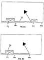
- the robotis able to calculate the time between the activation of the right and left bump switches 12 & 13, if both are activated. The robot is then able to estimate the angle at which contact was made.
- the bump sensorcomprises a single mechanical bumper 44 at the front of the robot with sensors 42 & 43 substantially at the two ends of the bumper that sense the movement of the bumper. When the bumper is compressed, the timing between the sensor events is used to calculate the approximate angle at which the robot contacted the obstacle. When the bumper is compressed from the right side, the right bump sensor detects the bump first, followed by the left bump sensor, due to the compliance of the bumper and the bump detector geometry. This way, the bump angle can be approximated with only two bump sensors.
- bump sensors 42 & 43are able to divide the forward portion of the robot into six regions (I-VI).
- the robotcalculates the time before the. other sensor is activated (if at all). For example, when the right bump sensor 43 is activated, the robot measures the time (t) before the left bump sensor 42 is activated. If t is less than t 1 , then the robot assumes contact occurred in region IV. If t is greater than or equal to t 1 and less than t 2 , then the robot assumes contact was made in region V.
- tis greater than or equal to t 2 (including the case of where the left bump sensor 42 is not activated at all within the time monitored)
- the robotassumes the contact occurred in region VI. If the bump sensors are activated simultaneously, the robot assumes the contact was made from straight ahead.
- This methodcan be used the divide the bumper into an arbitrarily large number of regions (for greater precision) depending on of the timing used and geometry of the bumper.
- three sensorscan be used to calculate the bump angle in three dimensions instead of just two dimensions as in the preceding example.
- a preferred embodimentalso contains a wall-following or wall-detecting sensor 16 mounted on the dominant side of the robot 10.
- the wall following sensoris an IR sensor composed of an emitter and detector pair collimated so that a finite volume of intersection occurs at the expected position of the wall. This focus point is approximately three inches ahead of the drive wheel in the direction of robot forward motion. The radial range of wall detection is about 0.75 inches.
- a preferred embodimentalso contains any number of IR cliff sensors 14 that prevent the device from tumbling over stairs or other vertical drops.
- These cliff sensorsare of a construction similar to that of the wall following sensor but directed to observe the floor rather than a wall.
- the robot 10includes a wheel-drop sensor that is able to detect if one or more wheels is unsupported by the floor. This wheel-drop sensor can therefore detect not only cliffs but also various obstacles upon which the robot is able to drive, such as lamps bases, high floor transitions, piles of cords, etc.
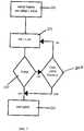
- FIG. 3shows a hardware block diagram of the controller and robot of a preferred embodiment of the invention.
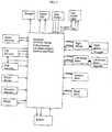
- a Winbond W78XXX series processoris used. It is a microcontroller compatible with the MCS-51 family with 36 general purpose I/O ports, 256 bytes of RAM and 16K of ROM. It is clocked at 40MHz which is divided down for a processor speed of 3.3 MHZ. It has two timers which are used for triggering interrupts used to process sensors and generate output signals as well as a watchdog timer. The lowest bits of the fast timer are also used as approximate random numbers where needed in the behaviours. There are also two external interrupts which are used to capture the encoder inputs from the two drive wheels.
- the processoralso has a DART which is used for testing and debugging the robot control program.
- the I/O ports of the microprocessorare connected to the sensors and motors of the robot and are the interface connecting it to the internal state of the robot and its environment.
- the wheel drop sensorsare connected to an input port and the brush motor PWM signal is generated on an output port.
- the ROM on the microprocessoris used to store the coverage and control program for the robot. This includes the behaviours (discussed below), sensor processing algorithms and signal generation.
- the RAMis used to store the active state of the robot, such as the average bump distance, run time and distance, and the ID of the behaviour in control and its current motor commands.
- FIG. 4Bshows the orientation of the robot 10 centered about the x and y axes in a coordinate plane; this coordinate system is attached to the robot.
- the directional movement of the robot 10can be understood to be the radius at which the robot 10 will move.
- the robot 10In order to rapidly turn away from the wall 1 00, the robot 10 should set a positive, small value of r (r 3 in FIG. 4B ); in order to rapidly turn toward the wall, the robot should set a negative, small value of r (r 1 in FIG. 4B ).
- the robotshould set larger absolute values for r - positive values to move left (i.e. away from the wall, r 4 in FIG.
- the robotmay include one or more user inputs.
- a preferred embodimentincludes three simple buttons 33 that allow the user to input the approximate size of the surface to be covered.
- these buttons labelled "small,” “medium,” and “large”correspond respectively to rooms of 11.1, 20.8 and 27.9 square metres.
- the exemplary robotis a preferred embodiment for practising the instant invention, and one of skill in the art is able to choose from elements known in the art to design a robot for a particular purpose.
- suitable designsinclude those described in the following U.S. Patents Nos: 4,306,329 (Yokoi ), 5,109,566 (Kobayashi et al. ), 5,293,955 (Lee ), 5,369,347 (Yoo ), 5,440,216 (Kim ), 5,534,762 (Kim ), 5,613,261 (Kawakami et al ), 5,634,237 (Paranjpe ), 5,781,960 (Kilstrom et al.
- FIG. 5shows a simple block representation of the' various operational modes of a device.
- operational modesmay include spot cleaning (where the user or robot designates a specific region for cleaning), edge cleaning, and room cleaning.
- spot cleaningwhere the user or robot designates a specific region for cleaning
- edge cleaningwhere the user or robot designates a specific region for cleaning
- room cleaningwhere the user or robot designates a specific region for cleaning
- Each operational modecomprises complex combinations of instructions and/or internal behaviours, discussed below. These complexities, however, are generally hidden from the user.
- the usercan select the particular operational mode by using an input element, for example, a selector switch or push button.
- the robotis able to autonomously cycle through the operational modes.
- the coverage robot of the instant inventionuses these various operational modes to effectively cover the area. While one of skill in the art may implement these various operational modes in a variety of known architectures, a preferred embodiment relies on behaviour control. Here, behaviours are simply layers of control systems that all run in parallel. The microcontroller 22 then runs a prioritized arbitration scheme to resolve the dominant behaviour for a given scenario. A description of behaviour control can be found in Mobile Robots, supra.
- the robot's microprocessor and control softwarerun a number of behaviours simultaneously.
- control of the robotwill be given to one or more various behaviours.
- the behaviourswill be described as (1) coverage behaviours, (2) escape behaviours or (3) user/safety behaviours.
- Coverage behavioursare primarily designed to allow the robot to perform its coverage operation in an efficient manner. Escape behaviours are special behaviours that are given priority when one or more sensor inputs suggest that the robot may not be operating freely. As a convention for this specification, behaviours discussed below are written in all capital letters.
- FIGS. 6-14show the details of each of the preferred operational modes: Spot Coverage, Wall Follow (or Obstacle Follow) and Room Coverage.
- Spot coverage or, for example, spot cleaningallows the user to clean an isolated dirty area.
- the userplaces the robot 10 on the floor near the centre of the area that requires cleaning and selects the spot-cleaning operational mode.
- the robotthen moves in such a way that the immediate area within, for example, a defined radius, is brought into contact with the cleaning head 30 or side brush 32 of the robot.
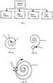
- the method of achieving spot cleaningis a control algorithm providing outward spiral movement, or SPIRAL behaviour, as shown in FIG.6A .
- spiral movementis generated by increasing the turning radius as a function of time.
- the robot 10begins its spiral in a counter-clockwise direction, marked in FIG. 6A by movement line 45, in order to keep the dominant side on the outward, leading-edge of the spiral.
- FIG. 6Bspiral movement of the robot 10 is generated inward such that the radius of the turns continues to decrease. The inward spiral is shown as movement line 45 in FIG. 6B . It is not necessary, however, to keep the dominant side of the robot on the outside during spiral motion.
- the method of spot cleaning used in a preferred embodiment - outward spiralling -is set forth in FIG. 7 .
- the spiralling behaviourrecalculates the value of r as a function of ⁇ , where ⁇ represents the angular turning since the initiation of the spiralling behaviour (step 210).
- ⁇a ⁇
- aa constant coefficient
- a value for dshould be chosen that is less than the width of the cleaning mechanism 30. In a preferred embodiment, a value of d is selected that is between one-half and two-thirds of the width of the cleaning head 30.
- the robottracks its total distance travelled in spiral mode. Because the spiral will deteriorate after some distance, i.e. the centerpoint of the spiral motion will tend to drift over time due to surface dependant wheel slippage and/or inaccuracies in the spiral approximation algorithm and calculation precision.
- the robotmay exit spiral mode after the robot has travelled a specific distance ("maximum spiral distance"), such as 6.3 or 18.5 metres (step 240).
- maximum spiral distancesuch as 6.3 or 18.5 metres
- the robotuses multiple maximum spiral distances depending on whether the robot is performing an initial spiral or a later spiral. If the maximum spiral distance is reached without a bump, the robot gives control to a different behaviour, and the robot, for example, then continues to move in a predominately straight line.
- a STRAIGHT LINE behaviouris a low priority, default behaviour that propels the robot in an approximate straight line at a preset velocity of approximately 0.306 m/s when no other behaviours are active.
- the robotcould (a) seek to avoid the obstacle and continue the spiral in the counter-clockwise direction, (b) seek to avoid the obstacle and continue the spiral in the opposite direction (e.g. changing from counter-clockwise to clockwise), or ⁇ change operational modes.
- the spiral in the opposite directionis known as reflective spiralling and is represented in FIG. 6C , where the robot 10 reverses its movement path 45 when it comes into contact with obstacle 101.
- the robot 10exits spot cleaning mode upon the first obstacle encountered by a bump sensor 12 or 13.
- any self-bounded areacan be used, including but not limited to regular polygon shapes such as squares, hexagons, ellipses, etc.
- Wall following or, in the case of a cleaning robot, edge cleaningallows the user to clean only the edges of a room or the edges of objects within a room.
- the userplaces the robot 10 on the floor near an edge to be cleaned and selects the edge- cleaning operational mode.
- the robot 10then moves in such a way that it follows the edge and cleans all areas brought into contact with the cleaning head 30 of the robot.
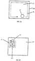
- FIG. 8The movement of the robot 10 in a room 110 is shown in FIG. 8 .
- the robot 10is placed along with wall 100, with the robot's dominant side next to the wall. The robot then runs along the wall indefinitely following movement path 46.
- FIG. 8Bthe robot 10 is placed in the proximity of an obstacle 101. The robot then follows the edge of the obstacle 101 indefinitely following movement path 47.
- the robotin the wall-following mode, uses the wall-following sensor 16 to position itself a set distance from the wall. The robot then proceeds to travel along the perimeter of the wall. As shown in FIGS. 8A & 8B , in a preferred embodiment, the robot 10 is not able to distinguish between a wall 100 and another solid obstacle 101.
- FIG. 9AThe method used in a preferred embodiment for following the wall is detailed in FIG. 9A and provides a smooth wall following" operation even with a one-bit sensor.
- the one-bit sensordetects only the presence of absence of the wall within a particular volume rather than the distance between wall and sensor.
- Other methods of detecting a wall or objectcan be used such as bump sensing or sonar sensors.
- the robotfirst sets its initial value for the steering at r 0 .
- the WALL-FOLLOWING behaviourthen initiates the emit-detect routine in the wail-follower sensor 16 (step 310).
- the existence of a reflection for the IR transmitter portion of the sensor 16translates into the existence of an object within a predetermined distance from the sensor 16.
- the WALL-FOLLOWING behaviourdetermines whether there has been a transition from a reflection (object within range) to a non-reflection (object outside of range) (step 320).
- the value of ris set to its most negative value and the robot will veer slightly to the right (step 325).
- the robotthen begins the emit-detect sequence again (step 310). If there has not been a transition from a reflection to a non-reflection, the wall-following behaviour then determines whether there has been a transition from non-reflection to reflection (step 330). If there has been such a transition, the value of r is set to its most positive value and the robot will veer slightly left (step 335).
- the wall-following behaviourreduces the absolute value of r (step 340) and begins the emit-detect sequence (step 310) anew.
- the rate of decreasing the absolute value of ris a constant rate dependant on the distance travelled.
- the wall follower modecan be continued for a predetermined or random time, a predetermined or random distance or until some additional criteria are met (e.g. bump sensor is activated, etc.).
- the robotcontinues to follow the wall indefinitely.
- minimum and maximum travel distancesare determined, whereby the robot will remain in WALL-FOLLOWING behaviour until the robot has either travelled the maximum distance ( FIG. 8D ) or travelled at least the minimum distance and encountered an obstacle ( FIG. 8C ).
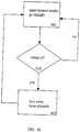
- FIG. 9Bis a flow-chart illustration showing this embodiment of determining when to exit WALL-FOLLOWING behaviour.
- the robotfirst determines the minimum distance to follow the wall (d min ) and the maximum distance to follow the wall (d max ). While in wall (or obstacle) following mode, the control system tracks the distance the robot has travelled in that mode (d WF ). If d DW is greater than d max (step 350), then the robot exits wall-following mode (step 380). If, however, d WF is less than d max (step 350) and d WF is less than d max (step 360), the robot remains in wall- following mode (step 385). If d WF is greater than d min (step 360) and an obstacle is encountered (step 370), the robot exits wall-following mode (step 380).
- the optimal distance for the robot to travel in WALL-FOLLOWING behaviouris a function of room size and configuration and robot size.
- the minimum and maximum distances to remain in WALL-FOLLOWINGare set based upon the approximate room size, the robots width and a random component, where by the average minimum travel distance is 2 w / p , where w is the width of the work element of the robot and p is the probability that the robot will enter WALL-FOLLOWING behaviour in a given interaction with an obstacle.
- wis approximately between 15 cm and 25 cm
- pis 0.09 5 (where the robot encounters 6 to 15 obstacles, or an average of 10.5 obstacles, before entering an obstacle following mode).
- the minimum distanceis then set randomly as a distance between approximately 115 em and 350 em; the maximum distance is then set randomly as a distance between approximately 170 em and 520 cm.
- the ratio between the minimum distance to the maximum distanceis 2:3.
- the robot's initial operation in a obstacle following modecan be set to be longer than its later operations in obstacle following mode.
- usersmay place the robot along the longest wall when starting the robot, which improves actual as well as perceived coverage.
- the distance that the robot travels in wall following modecan also be set by the robot depending on the number and frequency of objects encountered (as determined by other sensors), which is a measure of room "clutter.” If more objects are encountered, the robot would wall follow for a greater distance in order to get into all the areas of the floor. Conversely, if few obstacles are encountered, the robot would wall follow less in order to not over-cover the edges of the space in favour of passes through the centre of the space.
- An initial wall-following distancecan also be included to allow the robot to follow the wall a longer or shorter distance during its initial period where the WALL-FOLLOWING behaviour has control.
- the robotmay also leave wall-following mode if the robot turns more than, for example, 270 degrees and is unable to locate the wall (or object) or if the robot has turned a total of 360 degrees since entering wall-following mode.
- the ALIGN behaviourwhen the WALL-FOLLOWING behaviour is active and there is a bump, the ALIGN behaviour becomes active.
- the ALIGN behaviourturns the robot counter-clockwise to align the robot with the wall.
- the robotalways turns a minimum angle to avoid getting the robot getting into cycles of many small turns.
- the robotmonitors its wall sensor and if it detects a wall and then the wall detection goes away, the robot stops turning. This is because at the end of the wall follower range, the robot is well aligned to start WALL-FOLLOWING. If the robot has not seen its wall detector go on and then off by the time it reaches its maximum angle, it stops anyway. This prevents the robot from turning around in circles when the wall is out of range of its wall sensor.
- the minimum angleis set to 14 degrees and the maximum angle is 19 degrees. Otherwise, if the bump is within 30 degrees of the front of the bumper on the dominant side or on the non-dominant side, the minimum angle is 20 degrees and the maximum angle is 44 degrees.
- the ALIGN behaviourhas completed turning, it cedes control to the WALL-FOLLOWING behaviour.
- the third operational modeis here called room-coverage or room cleaning mode, which allows the user to clean any area bounded by walls, stairs, obstacles or other barriers.
- room-coverageor room cleaning mode, which allows the user to clean any area bounded by walls, stairs, obstacles or other barriers.
- the userplaces the robot on the floor and selects room-cleaning mode. The robot them moves about the room cleaning all areas that it is able to reach.
- the method of performing the room cleaning behaviouris a BOUNCE behaviour in combination with the STRAIGHT LINE behaviour.
- the robot 10travels until a bump sensor 12 and/or 13 is activated by contact with an obstacle 101 or a wall 100. The robot 10 then turns and continues to travel.
- a sample movement pathis shown in FIG. 11 as line 48.
- the algorithm for random bounce behaviouris set forth in FIG. 10 .
- the robot 10continues its forward movement (step 401) until a bump sensor 12 and/or 13 is activated (step 410).
- the robot 10then calculates an acceptable range of new directions based on a determination of which bump sensor or sensors have been activated (step 420).
- a determinationis then made with some random calculation to choose the new heading within that acceptable range, such as 90 to 270 degrees relative to the object the robot encountered.
- the angle of the object the robot has bumpedis determined as described above using the timing between the right and left bump sensors.
- the robotthen turns to its new headings. In a preferred embodiment, the turn is either clockwise or counterclockwise depending on which direction requires the least movement to achieve the new heading. In other embodiments, the turn is accompanied by movement forward in order to increase the robot's coverage efficiency.
- the statistics of the heading choice made by the robotcan be distributed uniformly across the allowed headings, i.e. there is an equivalent chance for any heading within the acceptable range. Alternately we can choose statistics based on a Gaussian or other distribution designed to preferentially drive the robot perpendicularly away from a wall.
- the robotcould change directions at random or predetermined times and not based upon external sensor activity.
- the robotcould continuously make small angle corrections based on long range sensors to avoid even contacting an object and, thereby cover the surface area with curved paths.
- the robotstays in room-cleaning mode until a certain number of bounce interactions are reached, usually between 6 and 13.
- escape behavioursare designed to get the robot out of these situations, or in extreme cases to shut the robot off if it is determined it cannot escape.
- the robotdetermines the following: (1) is an escape behaviour needed; (2) if yes, which escape behaviour is warranted?
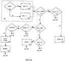
- FIGS. 12A & 12Billustrate the analysis used in a preferred embodiment for identifying the need for an escape behaviour relative to a stalled brush motor, as described above in Situations 1, 2 and 4.
- a rate registeris incremented by 1 (step 404); if no limit is detected, the rate register is decremented by 1 (step 406).
- a separate slope registerstores the recent values for a recent time period such as 120 cycles. If the rate is above 600 (where 600 corresponds to one second of constant stall) (step 414) and the slope is positive (step 416), then the robot will run an escape behaviour (step 420) if the escape behaviour is enabled (step 418). The escape behaviours are disabled after running (step 428) until the rate has returned to zero (step 422), re-enabled (step 424) and risen to 600 again. This is done to avoid the escape behaviour being triggered constantly at rates above 600.
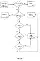
- step 410If, however, the rate is above 2400 (step 410) and the slope is positive (step 412), the robot will run a special set of escape behaviours, shown in FIG. 12B .
- the brush motorwill shut off (step 430), the "level" is incremented by a predetermined amount (50 to 90) (step 430), the stall time is set (step 430), and a panic behaviour (step 452) is preformed at 1 second (step 445), 4 seconds (step 450) and 7 seconds (step 455) since the brush shut off.
- the control systemthen restarts the brush at 13 seconds (steps 440 & 442). Level is decremented by 1 every second (steps 444). If level reaches a maximum threshold (step 435), the robot ceases all operation (step 437).
- the robotmay take additional actions when certain stalls are detected, such as limiting the voltage to the motor to prevent damage to the motor.
- a preferred embodiment of the robothas four escape behaviours: TURN, EDGE, WHEEL DROP and SLOW.
- the robotalso might contain additional behaviours related to safety or usability. For example, if a cliff is detected for more than a predetermined amount of time, the robot may shut off. When a cliff is first detected, a cliff avoidance response behaviour takes immediate precedence over all other behaviours, rotating the robot away from the cliff until the robot no longer senses the cliff. In a preferred embodiment, the cliff detection event does not cause a change in operational modes. In other embodiments, the robot could use an algorithm similar to the wall-following behaviour to allow for cliff following.
- a preferred embodimentuses a control program that gives priority to various coverage behaviours. (Escape behaviours, if needed, are always given a higher priority.)
- the robot 10may use the wall following mode for a specified or random time period and then switch operational modes to the room cleaning. By switching between operational modes, the robotic device of the present invention is able to increase coverage, cleaning efficiency and perceived effectiveness.
- FIGS. 13A & 13Bshow a mobile robot 10 a "dog bone" shaped environment in which two rooms 115 & 116 of roughly equal dimensions are connected by a narrow passageway 105.
- This arrangementis a simplified version of typical domestic environments, where the "dog bone” may be generated by the arrangements of obstacles within the room.
- the path of robot 10is traced as line 54 as robot 10 operates on in random bounce mode.
- the robot 10is unable to move from room 116 into 115 during the limited run because the robot's random behaviour did not happen to lead the robot through passageway 105.
- This methodleaves the coverage far less than optimal and the cleaning rate decreased due to the number of times the robot 10 crosses its own path.
- FIG. 13Bshows the movement of a preferred embodiment of robot 10, whereby the robot cycles between BOUNCE and WALL FOLLOWING behaviours.
- the robotfollows path 99, each time the robot 10 encounters a wall 100, the robot follows the wall for a distance equal to twice the robot's diameter.
- the portions of the path 99 in which the robot 10 operates in wall following modeare labelled 51. This method provides greatly increased coverage, along with attendant increases in cleaning rate and perceived effectiveness.
- the device 10begins in spiral mode (movement line 45). If a reflective spiral pattern is used, the device continues in spiral mode until a predetermined or random number of reflective events has occurred. If a standard spiral is used (as shown in FIG. 14 ), the device should continue until any bump sensor event. In a preferred embodiment, the device immediately enters wall following mode after the triggering event.
- the devicethen switches between wall following mode (movement lines 51) and random bounce modes (movement lines 48) based on bump sensor events or the completion of the wall following algorithm. In one embodiment, the device does not return to spiral mode; in other embodiments, however, the device can enter spiral mode based on a predetermined or random event.
- the robotkeeps a record of the average distance travelled between bumps.
- the robotthen calculates an average bump distance (ABD) using the following formula: (3/4 x ABD) + (1/4 x most recent distance between bumps). If the ABD is a above a predetermined threshold, the robot will again give priority to the SPIRAL behaviour. In still other embodiments, the robot may have a minimum number of bump events before the SPIRAL behaviour will again be given priority. In other embodiments, the robot may enter SPIRAL behaviour if it travels a maximum distance, for example 20 feet, without a bump event.
- the robotcan also have conditions upon which to stop all operations. For example, for a given room size, which can be manually selected, a minimum and maximum run time are set and a minimum total distance is selected. When the minimum time and the minimum distance have been reached the robot shuts off. Likewise, if the maximum time has been reached, the robot shuts off.
- a manual control for selecting between operational modescan also be used.
- a remote controlcould be used to change or influence operational modes or behaviours.
- a switch mounted on the shell itselfcould be used to set the operation mode or the switching between modes.
- a switchcould be used to set the level of clutter in a room to allow the robot a more appropriate coverage algorithm with limited sensing ability.
Landscapes
- Engineering & Computer Science (AREA)
- Automation & Control Theory (AREA)
- Radar, Positioning & Navigation (AREA)
- Remote Sensing (AREA)
- Physics & Mathematics (AREA)
- General Physics & Mathematics (AREA)
- Aviation & Aerospace Engineering (AREA)
- Control Of Position, Course, Altitude, Or Attitude Of Moving Bodies (AREA)
- Electric Vacuum Cleaner (AREA)
- Manipulator (AREA)
- Electric Suction Cleaners (AREA)
- Numerical Control (AREA)
- Cleaning In General (AREA)
Abstract
Description
- This invention relates generally to autonomous vehicles or robots, and more specifically to methods and mobile robotic devices for covering a specific area as might be required of, or used as, robotic cleaners or lawn mowers.
- For purposes of this description, examples will focus on the problems faced in the prior art as related to robotic cleaning (e.g., dusting, buffing, sweeping, scrubbing, dry mopping or vacuuming). The claimed invention, however, is limited only by the claims themselves, and one of skill in the art will recognize the myriad of uses for the present invention beyond indoor, domestic cleaning.
- Robotic engineers have long worked on developing an effective method of autonomous cleaning. By way of introduction, the performance of cleaning robots should concentrate on three measures of success: coverage, cleaning rate and perceived effectiveness. Coverage is the percentage of the available space visited by the robot during a fixed cleaning time, and ideally, a robot cleaner would provide 100 percent coverage given an infinite run time. Unfortunately, designs in the prior art often leave portions of the area uncovered regardless of the amount of time the device is allowed to complete its tasks. Failure to achieve complete coverage can result from mechanical limitations - e.g. the size and shape of the robot may prevent it from reaching certain areas -- or the robot may become trapped, unable to vary its control to escape. Failure to achieve complete coverage can also result from an inadequate coverage algorithm. The coverage algorithm is the set of instructions used by the robot to control its movement. For the purposes of the present invention,
coverage is discussed as a percentage of the available area visited by the robot during a finite cleaning time. Due to mechanical and/or algorithmic limitations, certain areas within the available space may be systematically neglected. Such systematic neglect is a significant limitation in the prior art. - A second measure of a cleaning robot's performance is the cleaning rate given in units of area cleaned per unit time. Cleaning rate refers to the rate at which the area of cleaned floor increases; coverage rate refers to the rate at which the robot covers the floor regardless of whether the floor was previously clean or dirty. If the velocity of the robot isv and the width of the robot's cleaning mechanism (also called work width) isw then the robot's coverage rate is simplywv, but its cleaning rate may be drastically lower.
- A robot that moves in a purely randomly fashion in a closed environment has a cleaning rate that decreases relative to the robot's coverage rate as a function of time. This is because the longer the robot operates the more likely it is to revisit already cleaned areas. The optimal design has a cleaning rate equivalent to the coverage rate, thus minimizing unnecessary repeated cleanings of the same spot. In other words, the ratio of cleaning rate to coverage rate is a measure of efficiency and an optimal cleaning rate would mean coverage of the greatest percentage of the designated area with the minimum number of cumulative or redundant passes over an area already cleaned.
- A third metric of cleaning robot performance is the perceived effectiveness of the robot. This measure is ignored in the prior art. Deliberate movement and certain patterned movement is favoured as users will perceive a robot that contains deliberate movement as more effective.
- While coverage, cleaning rate and perceived effectiveness are the performance criteria discussed herein, a preferred embodiment of the present invention also takes into account the ease of use in rooms of a variety of shapes and sizes (containing a variety of unknown obstacles) and the cost of the robotic components. Other design criteria may also influence the design, for example the need for collision avoidance and appropriate response to other hazards.
- As described in detail inJones, Flynn & Seiger, Mobile Robots: Inspiration to Implementation second edition, 1999, A K Peters, Ltd., and elsewhere, numerous attempts have been made to build vacuuming and cleaning robots. Each of these robots has faced a similar challenge: how to efficiently cover the designated area given limited energy reserves.
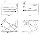
- We refer to maximally efficient cleaning, where the cleaning rate equals the coverage rate, as deterministic cleaning. As shown in
FIG. 1A , arobot 1 following a deterministic path moves in such a way as to completely cover the area 2 while avoiding all redundant cleaning. Deterministic cleaning requires that the robot know both where it is and where it has been; this in turn requires a positioning system. Such a positioning system - a positioning system suitably accurate to enable deterministic cleaning might rely on scanning laser rangers, ultrasonic transducers, carrier phase differential GPS, or other methods - can be prohibitively expensive and involve user set-up specific to the particular room geometries. Also, methods that rely on global positioning are typically incapacitated by the failure of any part of the positioning system. - One example of using highly sophisticated (and expensive) sensor technologies to create deterministic cleaning is the RoboScrub device built by Denning Mobile Robotics and Windsor Industries, which used sonar, infrared detectors, bump sensors and high-precision laser navigation. RoboScrub's navigation system required attaching large bar code targets at various positions in the room. The requirement that RoboScrub be able to see at least four targets simultaneously was a significant operational problem. RoboScrub, therefore, was limited to cleaning large open areas.
- Another example, RoboKent, a robot built by the Kent Corporation, follows a global positioning strategy similar to RobotScrub. RoboKent dispenses with RobotScrub's more expensive laser positioning system but having done so RoboKent must restrict itself only to areas with a simple rectangular geometry, e.g., long hallways. In these more constrained regions, position correction by sonar ranging measurements is sufficient. Other deterministic cleaning systems are described, for example, in
U.S. Patent Nos. 4,119,900 (Kremnitz ),4,700,427 (Knepper ),5,353,224 (Lee et al. ),5,537,017 (Feiten et al. ),5,548,511 (Bancroft ),5,650,702 (Azumi ). - Because of the limitations and difficulties of deterministic cleaning, some robots have relied on pseudo-deterministic schemes. One method of providing pseudo-deterministic cleaning is an autonomous navigation method known as dead reckoning. Dead reckoning consists of measuring the precise rotation of each robot drive wheel (using for example optical shaft encoders). The robot can then calculate its expected position in the environment given a known starting point and orientation. One problem with this technique is wheel slippage. If slippage occurs, the encoder on that wheel registers a wheel rotation even though that wheel is not driving the robot relative to the ground. As shown in
FIG. 1B , as therobot 1 navigates about the room, these drive wheel slippage errors accumulate making this type of system unreliable for runs of any substantial duration. (The path no longer consists of tightly packed rows, as compared to the deterministic coverage shown inFIG. 1A .) The result of reliance on dead reckoning is intractable systematic neglect; in other words, areas of the floor are not cleaned. - One example of a pseudo-deterministic a system is the Cye robot from Probotics, Inc. Cye depends exclusively on dead reckoning and therefore takes heroic measures to maximize the performance of its dead reckoning system. Cye must begin at a user-installed physical registration spot in a known location where the robot fixes its position and orientation. Cye then keeps track of position as it moves away from that spot. As Cye moves, uncertainty in its position and orientation increase. Cye must make certain to return to a calibration spot before this error grows so large that it will be unlikely to locate a calibration spot. If a calibration spot is moved or blocked or if excessive wheel slippage occurs then Cye can become lost (possibly without realizing that it is lost). Thus Cye is suitable for use only in relatively small benign environments. Other examples of this approach are disclosed in
U.S. Patent Nos. 5,109,566 (Kobayashi et al. ) and6,255,793 (Peless et al. ). - Another approach to robotic cleaning is purely random motion. As shown in
FIG. 1C , in a typical room without obstacles, a random movement algorithm will provide acceptable coverage given significant cleaning time. Compared to a robot with a deterministic algorithm, a random cleaning robot must operate for a longer time to achieve acceptable coverage. To have high confidence that the random-motion robot has cleaned 98% of an obstacle-free room, the random motion robot must run approximately five times as long as a deterministic robot with the same cleaning mechanism moving at the same speed.
The coverage limitations of a random algorithm can be seen inFIG. 1D . An obstacle 5 in the room can create the effect of segmenting the room into a collection of chambers. The coverage over time of a random algorithm robot in such a room is analogous to the time density of gas released in one chamber of a confined volume. Initially, the density of gas is highest in the chamber where it is released and-lowest in more distant chambers. Similarly the robot is most likely to thoroughly clean the chamber where it starts, rather than more distant chambers, early in the process. Given enough time a gas reaches equilibrium with equal density in all chambers. Likewise given time, the robot would clean all areas thoroughly. The limitations of practical power supplies, however, usually guarantee that the robot will have insufficient time to clean all areas of a space cluttered with obstacles. We refer to this phenomenon as the robot diffusion problem.
As discussed, the commercially available prior art has not been able to produce an effective coverage algorithm for an area of unknown geometry. As noted above, the prior art either has relied on sophisticated systems of markers or beacons or has limited the utility of the robot to rooms with simple rectangular geometries. Attempts to use pseudo-deterministic control algorithms can leave areas of the space systematically neglected.
U.S. patentUS 5,942,869 discloses a control device for a mobile robot and particularly, a control device for a mobile robot which allows the robot to run through a narrow passage and/or between obstacles with a minimum of hunting and zigzag motion and a less number of turns and to escape from its deadlock state where the robot is stalled in a limited location such as a corner in a target area for the robot to run throughout. - The present invention relates to a mobile robot as set out in
claim 1. Other embodiments are described in the dependent claims. - It is an object of the present invention to provide a system and method to allow a mobile robot to operate in a plurality of modes in order to effectively cover an area. It is an object of a preferred embodiment of the invention to use a control system for a mobile robot with an operational system program able to run a plurality of behaviours and using an arbiter to select which behaviour is given control over the robot.
- It is still another object of the invention to incorporate various escape programs or behaviour to allow the robot to avoid becoming stuck.
- These and further features of the present invention will be apparent with reference to the accompanying drawings, wherein:
FIGS. 1 A-D illustrate coverage patterns of various robots in the prior art;FIG. 2 is a top-view schematic representation of the basic components of a mobile robot used in a preferred embodiment of the invention;FIG. 3 demonstrates a hardware block diagram of the robot shown inFIG. 2 ;FIG. 4A is a diagram showing a method of determining the angle at which the robot encounters an obstacle;FIG. 4B is a diagram showing the orientation of a preferred embodiment of the robot control system;FIG. 5 is a schematic representation of the operational modes of the instant invention;FIG. 6A is a schematic representation of the coverage pattern for a preferred embodiment of SPIRAL behaviour;FIG. 6B is a schematic representation of the coverage pattern for an alternative embodiment of SPIRAL behaviour;FIG. 6C is a schematic representation of the coverage pattern for yet another alternative embodiment of SPIRAL behaviour;FIG. 7 is a flow-chart illustration of the spot-coverage algorithm of a preferred embodiment of the invention;FIGS. 8A & 8B are schematic representations of the coverage pattern for a preferred embodiment of operation in obstacle following mode;FIG. 9A is a flow-chart illustration of the obstacle following algorithm of a preferred embodiment of the invention;FIG. 9B is a flow-chart illustration of a preferred algorithm for determining when to exit obstacle following mode.FIG. 10 is a schematic representation of the coverage pattern for a preferred embodiment of BOUNCE behaviour;FIG. 11 is a flow-chart illustration of the room coverage algorithm, of a preferred embodiment of the invention;FIGS. 12A &12B are flow-chart illustrations of an exemplary escape behaviour;FIG. 13A is a schematic representation of the coverage pattern a mobile robot with only a single operational mode;FIG. 13B is a schematic representation of the coverage pattern for a preferred embodiment of the instant invention using obstacle following and room coverage modes; andFIG. 14 is a schematic representation of the coverage pattern for a preferred embodiment of the instant invention using spot-coverage, obstacle following and room coverage modes.- In the present invention, a mobile robot is designed to provide maximum coverage at an effective coverage rate in a room of unknown geometry. In addition, the perceived effectiveness of the robot is enhanced by the inclusion of patterned or deliberate motion. In addition, in a preferred embodiment, effective coverage requires a control system able to prevent the robot from becoming immobilized in an unknown environment.
- While the physical structures of mobile robots are known in the art, the components of a preferred, exemplary embodiment of the present invention is described herein. A preferred embodiment of the present invention is a substantially circular robotic sweeper containing certain features. As shown in
FIG. 2 , for example, themobile robot 10 of a preferred embodiment includes a chassis 11 supporting mechanical and electrical components. These components include various sensors, including twobump sensors 12 & 13 located in the forward portion of the robot, fourcliff sensors 14 located on therobot shell 15, and awall following sensor 16 mounted on therobot shell 15. In other embodiments, as few as one sensor may be used in the robot. One of skill in the art will recognize that the sensor(s) may be of a variety of types including sonar, tactile, electromagnetic, capacitive, etc. Because of cost restraints, a preferred embodiment of the present invention uses bump (tactile)sensors 12 & 13 and reflective IR proximity sensors for thecliff sensors 14 and the wall-followingsensor 16. Details of the IR sensors are described in U.S. Patent Application U.S.S.N.09/768,773 - A preferred embodiment of the robot also contains two
wheels 20,motors 21 for driving the wheels independently, an inexpensive low-end microcontroller 22, and arechargeable battery 23 or other power source known in the art. These components are well known in the art and are not discussed in detail herein. Therobotic cleaning device 10 further includes one or more cleaning heads 30. The cleaning head might contain a vacuum cleaner, various brushes, sponges, mops, electrostatic cloths or a combination of various cleaning elements. The embodiment shown inFIG. 2 also includes aside brush 32. - As mentioned above, a preferred embodiment of the
robotic cleaning device 10 comprises anouter shell 15 defining a dominant side, non-dominant side, and a front portion of therobot 10. The dominant side of the robot is the side that is kept near or in contact with an object (or obstacle) when the robot cleans the area adjacent to that object (or obstacle). In a preferred embodiment, as shown inFIG. 1 , the dominant side of therobot 10 is the right-hand side relative to the primary direction of travel, although in other embodiments the dominant side may be the left-hand side. In still other embodiments, the robot may be symmetric and thereby does not need a dominant side; however, in a preferred embodiment, a dominant side is
chosen for reasons of cost. The primary direction of travel is as shown inFIG. 2 byarrow 40. - In a preferred embodiment, two
bump sensors 12 & 13 are located forward of thewheels 20 relative to the direction of forward movement, shown byarrow 40. Onebump sensor 13 is located on the dominant side of therobot 10 and theother bump sensor 12 is located on the non-dominant side of therobot 10. When both of thesebump sensors 12 & 13 are activated simultaneously, therobot 10 recognizes an obstacle in the front position. In other embodiments, more or fewer individual bump sensors can be used. Likewise, any number of bump sensors can be used to divide the device into any number of radial segments. While in a preferred embodiment thebump sensors 12 & 13 are IR break beam sensors activated by contact between therobot 10 and an obstacle, other types of sensors can be used, including mechanical switches and capacitive sensors that detect the capacitance of objects touching the robot or between two metal plates in the bumper that are compressed on contact. Non-contact sensors, which allow the robot to sense proximity to objects without physically touching the object, such as capacitive sensors or a curtain of IR light, can also be used. - It is useful to have a sensor or sensors that are not only able to tell if a surface has been contacted (or is nearby), but also the angle relative to the robot at which the contact was made. In the case of a preferred embodiment, the robot is able to calculate the time between the activation of the right and left bump switches 12 & 13, if both are activated. The robot is then able to estimate the angle at which contact was made. In a preferred embodiment shown in
FIG. 4A , the bump sensor comprises a singlemechanical bumper 44 at the front of the robot with sensors 42 & 43 substantially at the two ends of the bumper that sense the movement of the bumper. When the bumper is compressed, the timing between the sensor events is used to calculate the approximate angle at which the robot contacted the obstacle. When the bumper is compressed from the right side, the right bump sensor detects the bump first, followed by the left bump sensor, due to the compliance of the bumper and the bump detector geometry. This way, the bump angle can be approximated with only two bump sensors. - For example, in
FIG. 4A , bump sensors 42 & 43 are able to divide the forward portion of the robot into six regions (I-VI). When a bump sensor is activated, the robot calculates the time before the. other sensor is activated (if at all). For example, when the right bump sensor 43 is activated, the robot measures the time (t) before the left bump sensor 42 is activated. If t is less than t1, then the robot assumes contact occurred in region IV. If t is greater than or equal to t1 and less than t2, then the robot assumes contact was made in region V. If t is greater than or equal to t2 (including the case of where the left bump sensor 42 is not activated at all within the time monitored), then the robot assumes the contact occurred in region VI. If the bump sensors are activated simultaneously, the robot assumes the contact was made from straight ahead. This method can be used the divide the bumper into an arbitrarily large number of regions (for greater precision) depending on of the timing used and geometry of the bumper. As an extension, three sensors can be used to calculate the bump angle in three dimensions instead of just two dimensions as in the preceding example. - A preferred embodiment also contains a wall-following or wall-detecting
sensor 16 mounted on the dominant side of therobot 10. In a preferred embodiment, the wall following sensor is an IR sensor composed of an emitter and detector pair collimated so that a finite volume of intersection occurs at the expected position of the wall. This focus point is approximately three inches ahead of the drive wheel in the direction of robot forward motion. The radial range of wall detection is about 0.75 inches. - A preferred embodiment also contains any number of
IR cliff sensors 14 that prevent the device from tumbling over stairs or other vertical drops. These cliff sensors are of a construction similar to that of the wall following sensor but directed to observe the floor rather than a wall. As an additional safety and sensing measure, therobot 10 includes a wheel-drop sensor that is able to detect if one or more wheels is unsupported by the floor. This wheel-drop sensor can therefore detect not only cliffs but also various obstacles upon which the robot is able to drive, such as lamps bases, high floor transitions, piles of cords, etc. - Other embodiments may use other known sensors or combinations of sensors.
FIG. 3 shows a hardware block diagram of the controller and robot of a preferred embodiment of the invention. In a preferred embodiment, a Winbond W78XXX series processor is used. It is a microcontroller compatible with the MCS-51 family with 36 general purpose I/O ports, 256 bytes of RAM and 16K of ROM. It is clocked at 40MHz which is divided down for a processor speed of 3.3 MHZ. It has two timers which are used for triggering interrupts used to process sensors and generate output signals as well as a watchdog timer. The lowest bits of the fast timer are also used as approximate random numbers where needed in the behaviours. There are also two external interrupts which are used to capture the encoder inputs from the two drive wheels. The processor also has a DART which is used for testing and debugging the robot control program.- The I/O ports of the microprocessor are connected to the sensors and motors of the robot and are the interface connecting it to the internal state of the robot and its environment. For example, the wheel drop sensors are connected to an input port and the brush motor PWM signal is generated on an output port. The ROM on the microprocessor is used to store the coverage and control program for the robot. This includes the behaviours (discussed below), sensor processing algorithms and signal generation. The RAM is used to store the active state of the robot, such as the average bump distance, run time and distance, and the ID of the behaviour in control and its current motor commands.
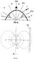
- For purposes of understanding the movement of the robotic device,
FIG. 4B shows the orientation of therobot 10 centered about the x and y axes in a coordinate plane; this coordinate system is attached to the robot. The directional movement of therobot 10 can be understood to be the radius at which therobot 10 will move. In order to rapidly turn away from thewall 1 00, therobot 10 should set a positive, small value of r (r3 inFIG. 4B ); in order to rapidly turn toward the wall, the robot should set a negative, small value of r (r1 inFIG. 4B ). On the other hand, to make slight turns, the robot should set larger absolute values for r - positive values to move left (i.e. away from the wall, r4 inFIG. 4B ) and negative values to move right (i.e. toward the wall, (r2 inFIG. 4B ). This coordinate scheme is used in the examples of control discussed below. Themicrocontroller 22 controlling differential speed at which theindividual wheel motors 21 are run, determines the turning radius.
Also, in certain embodiments, the robot may include one or more user inputs. For example, as shown inFIG. 2 , a preferred embodiment includes threesimple buttons 33 that allow the user to input the approximate size of the surface to be covered. In a preferred embodiment, these buttons labelled "small," "medium," and "large" correspond respectively to rooms of 11.1, 20.8 and 27.9 square metres.
As mentioned above, the exemplary robot is a preferred embodiment for practising the instant invention, and one of skill in the art is able to choose from elements known in the art to design a robot for a particular purpose. Examples of suitable designs include those described in the followingU.S. Patents Nos: 4,306,329 (Yokoi ),5,109,566 (Kobayashi et al. ),5,293,955 (Lee ),5,369,347 (Yoo ),5,440,216 (Kim ),5,534,762 (Kim ),5,613,261 (Kawakami et al ),5,634,237 (Paranjpe ),5,781,960 (Kilstrom et al. ),5,787,545 (Colens ),5,815,880 (Nakanishi ),5,839,156 (Park et al. ),5,926,909 (McGee ),6,038,501 (Kawakami ),6,076,226 (Reed ).FIG. 5 shows a simple block representation of the' various operational modes of a device. In a preferred embodiment, and by way of example only, operational modes may include spot cleaning (where the user or robot designates a specific region for cleaning), edge cleaning, and room cleaning. Each operational mode comprises complex combinations of instructions and/or internal behaviours, discussed below. These complexities, however, are generally hidden from the user. In one embodiment, the user can select the particular operational mode by using an input element, for example, a selector switch or push button. In other preferred embodiments, as described below, the robot is able to autonomously cycle through the operational modes.
The coverage robot of the instant invention uses these various operational modes to effectively cover the area. While one of skill in the art may implement these various operational modes in a variety of known architectures, a preferred embodiment relies on behaviour control. Here, behaviours are simply layers of control systems that all run in parallel. Themicrocontroller 22 then runs a prioritized arbitration scheme to resolve the dominant behaviour for a given scenario. A description of behaviour control can be found in Mobile Robots, supra. - In other words, in a preferred embodiment, the robot's microprocessor and control software run a number of behaviours simultaneously. Depending on the situation, control of the robot will be given to one or more various behaviours. For purposes of detailing the preferred operation of the present invention, the behaviours will be described as (1) coverage behaviours, (2) escape behaviours or (3) user/safety behaviours. Coverage behaviours are primarily designed to allow the robot to perform its coverage operation in an efficient manner. Escape behaviours are special behaviours that are given priority when one or more sensor inputs suggest that the robot may not be operating freely. As a convention for this specification, behaviours discussed below are written in all capital letters.
FIGS. 6-14 show the details of each of the preferred operational modes: Spot Coverage, Wall Follow (or Obstacle Follow) and Room Coverage.- Spot coverage or, for example, spot cleaning allows the user to clean an isolated dirty area. The user places the
robot 10 on the floor near the centre of the area that requires cleaning and selects the spot-cleaning operational mode. The robot then moves in such a way that the immediate area within, for example, a defined radius, is brought into contact with the cleaninghead 30 orside brush 32 of the robot. - In a preferred embodiment, the method of achieving spot cleaning is a control algorithm providing outward spiral movement, or SPIRAL behaviour, as shown in
FIG.6A . In general, spiral movement is generated by increasing the turning radius as a function of time. In a preferred embodiment, therobot 10 begins its spiral in a counter-clockwise direction, marked inFIG. 6A bymovement line 45, in order to keep the dominant side on the outward, leading-edge of the spiral. In another embodiment, shown inFIG. 6B , spiral movement of therobot 10 is generated inward such that the radius of the turns continues to decrease. The inward spiral is shown asmovement line 45 inFIG. 6B . It is not necessary, however, to keep the dominant side of the robot on the outside during spiral motion. - The method of spot cleaning used in a preferred embodiment - outward spiralling - is set forth in
FIG. 7 . Once the spiralling is initiated (step 201) and the value of r is set at its minimum, positive value (which will produce the tightest possible counterclockwise turn), the spiralling behaviour recalculates the value of r as a function of θ, where θ represents the angular turning since the initiation of the spiralling behaviour (step 210). By using the equation r = aθ, where a is a constant coefficient, the tightness or desired overlap of the spiral can be controlled. (Note that θ is not normalized to 2π). The value of a can be chosen by the equation a = d/2π; where d is the distance between two consecutive passes of the spiral. For effective cleaning, a value for d should be chosen that is less than the width of thecleaning mechanism 30. In a preferred embodiment, a value of d is selected that is between one-half and two-thirds of the width of the cleaninghead 30. - In other embodiments, the robot tracks its total distance travelled in spiral mode. Because the spiral will deteriorate after some distance, i.e. the centerpoint of the spiral motion will tend to drift over time due to surface dependant wheel slippage and/or inaccuracies in the spiral approximation algorithm and calculation precision. In certain embodiments, the robot may exit spiral mode after the robot has travelled a specific distance ("maximum spiral distance"), such as 6.3 or 18.5 metres (step 240). In a preferred embodiment, the robot uses multiple maximum spiral distances depending on whether the robot is performing an initial spiral or a later spiral. If the maximum spiral distance is reached without a bump, the robot gives control to a different behaviour, and the robot, for example, then continues to move in a predominately straight line. (In a preferred embodiment, a STRAIGHT LINE behaviour is a low priority, default behaviour that propels the robot in an approximate straight line at a preset velocity of approximately 0.306 m/s when no other behaviours are active.
- In spiral mode, various actions can be taken when an obstacle is encountered. For example, the robot could (a) seek to avoid the obstacle and continue the spiral in the counter-clockwise direction, (b) seek to avoid the obstacle and continue the spiral in the opposite direction (e.g. changing from counter-clockwise to clockwise), or © change operational modes. Continuing the spiral in the opposite direction is known as reflective spiralling and is represented in
FIG. 6C , where therobot 10 reverses itsmovement path 45 when it comes into contact withobstacle 101. In a preferred embodiment, as detailed instep 220, therobot 10 exits spot cleaning mode upon the first obstacle encountered by abump sensor - While a preferred embodiment describes a spiral motion for spot coverage, any self-bounded area can be used, including but not limited to regular polygon shapes such as squares, hexagons, ellipses, etc.
- Wall following or, in the case of a cleaning robot, edge cleaning, allows the user to clean only the edges of a room or the edges of objects within a room. The user places the
robot 10 on the floor near an edge to be cleaned and selects the edge- cleaning operational mode. Therobot 10 then moves in such a way that it follows the edge and cleans all areas brought into contact with the cleaninghead 30 of the robot. - The movement of the
robot 10 in aroom 110 is shown inFIG. 8 . InFIG. 8A , therobot 10 is placed along withwall 100, with the robot's dominant side next to the wall. The robot then runs along the wall indefinitely followingmovement path 46. Similarly, inFIG. 8B , therobot 10 is placed in the proximity of anobstacle 101. The robot then follows the edge of theobstacle 101 indefinitely followingmovement path 47. - In a preferred embodiment, in the wall-following mode, the robot uses the wall-following
sensor 16 to position itself a set distance from the wall. The robot then proceeds to travel along the perimeter of the wall. As shown inFIGS. 8A & 8B , in a preferred embodiment, therobot 10 is not able to distinguish between awall 100 and anothersolid obstacle 101. - The method used in a preferred embodiment for following the wall is detailed in
FIG. 9A and provides a smooth wall following" operation even with a one-bit sensor. (Here the one-bit sensor detects only the presence of absence of the wall within a particular volume rather than the distance between wall and sensor.) Other methods of detecting a wall or object can be used such as bump sensing or sonar sensors. - Once the wall-following operational mode, or WALL FOLLOWING behaviour of a preferred embodiment, is initiated (step 301), the robot first sets its initial value for the steering at r0. The WALL-FOLLOWING behaviour then initiates the emit-detect routine in the wail-follower sensor 16 (step 310). The existence of a reflection for the IR transmitter portion of the
sensor 16 translates into the existence of an object within a predetermined distance from thesensor 16. The WALL-FOLLOWING behaviour then determines whether there has been a transition from a reflection (object within range) to a non-reflection (object outside of range) (step 320). If there has been a transition (in other words, the wall is now out of range), the value of r is set to its most negative value and the robot will veer slightly to the right (step 325). The robot then begins the emit-detect sequence again (step 310). If there has not been a transition from a reflection to a non-reflection, the wall-following behaviour then determines whether there has been a transition from non-reflection to reflection (step 330). If there has been such a transition, the value of r is set to its most positive value and the robot will veer slightly left (step 335). - In the absence of either type of transition event, the wall-following behaviour reduces the absolute value of r (step 340) and begins the emit-detect sequence (step 310) anew. By decreasing the absolute value of r, the
robot 10 begins to turn more sharply in whatever direction it is currently heading. In a preferred embodiment, the rate of decreasing the absolute value of r is a constant rate dependant on the distance travelled. - The wall follower mode can be continued for a predetermined or random time, a predetermined or random distance or until some additional criteria are met (e.g. bump sensor is activated, etc.). In one embodiment, the robot continues to follow the wall indefinitely. In a preferred embodiment, as shown in
FIGS. 8C & 8D , minimum and maximum travel distances are determined, whereby the robot will remain in WALL-FOLLOWING behaviour until the robot has either travelled the maximum distance (FIG. 8D ) or travelled at least the minimum distance and encountered an obstacle (FIG. 8C ). This implementation of WALL-FOLLOWING behaviour ensures the robot spends an appropriate amount of time in WALL-FOLLOWING behaviour as compared to its other operational modes, thereby decreasing systemic neglect and distributing coverage to all areas. By increasing wall following, the robot is able to move in more spaces, but the robot is less efficient at cleaning anyone space. In addition, by tending to exit WALL-FOLLOWING behaviour after obstacle detection, the robot increases its perceived effectiveness. FIG. 9B is a flow-chart illustration showing this embodiment of determining when to exit WALL-FOLLOWING behaviour. The robot first determines the minimum distance to follow the wall (dmin) and the maximum distance to follow the wall (dmax). While in wall (or obstacle) following mode, the control system tracks the distance the robot has travelled in that mode (dWF). If dDW is greater than dmax (step 350), then the robot exits wall-following mode (step 380). If, however, dWF is less than dmax (step 350) and dWF is less than dmax (step 360), the robot remains in wall- following mode (step 385). If dWF is greater than dmin (step 360) and an obstacle is encountered (step 370), the robot exits wall-following mode (step 380).- Theoretically, the optimal distance for the robot to travel in WALL-FOLLOWING behaviour is a function of room size and configuration and robot size. In a preferred embodiment, the minimum and maximum distances to remain in WALL-FOLLOWING are set based upon the approximate room size, the robots width and a random component, where by the average minimum travel distance is 2w/p, where w is the width of the work element of the robot andp is the probability that the robot will enter WALL-FOLLOWING behaviour in a given interaction with an obstacle. By way of example, in a preferred embodiment,w is approximately between 15 cm and 25 cm, andp is 0.09 5 (where the robot encounters 6 to 15 obstacles, or an average of 10.5 obstacles, before entering an obstacle following mode). The minimum distance is then set randomly as a distance between approximately 115 em and 350 em; the maximum distance is then set randomly as a distance between approximately 170 em and 520 cm. In certain embodiments the ratio between the minimum distance to the maximum distance is 2:3. For the sake of perceived efficiency, the robot's initial operation in a obstacle following mode can be set to be longer than its later operations in obstacle following mode. In addition, users may place the robot along the longest wall when starting the robot, which improves actual as well as perceived coverage.
- The distance that the robot travels in wall following mode can also be set by the robot depending on the number and frequency of objects encountered (as determined by other sensors), which is a measure of room "clutter." If more objects are encountered, the robot would wall follow for a greater distance in order to get into all the areas of the floor. Conversely, if few obstacles are encountered, the robot would wall follow less in order to not over-cover the edges of the space in favour of passes through the centre of the space. An initial wall-following distance can also be included to allow the robot to follow the wall a longer or shorter distance during its initial period where the WALL-FOLLOWING behaviour has control.
- In a preferred embodiment, the robot may also leave wall-following mode if the robot turns more than, for example, 270 degrees and is unable to locate the wall (or object) or if the robot has turned a total of 360 degrees since entering wall-following mode.
- In certain embodiments, when the WALL-FOLLOWING behaviour is active and there is a bump, the ALIGN behaviour becomes active. The ALIGN behaviour turns the robot counter-clockwise to align the robot with the wall. The robot always turns a minimum angle to avoid getting the robot getting into cycles of many small turns. After it has turned through its minimum angle, the robot monitors its wall sensor and if it detects a wall and then the wall detection goes away, the robot stops turning. This is because at the end of the wall follower range, the robot is well aligned to start WALL-FOLLOWING. If the robot has not seen its wall detector go on and then off by the time it reaches its maximum angle, it stops anyway. This prevents the robot from turning around in circles when the wall is out of range of its wall sensor. When the most recent bump is within the side 60 degrees of the bumper on the dominant side, the minimum angle is set to 14 degrees and the maximum angle is 19 degrees. Otherwise, if the bump is within 30 degrees of the front of the bumper on the dominant side or on the non-dominant side, the minimum angle is 20 degrees and the maximum angle is 44 degrees. When the ALIGN behaviour has completed turning, it cedes control to the WALL-FOLLOWING behaviour.
- The third operational mode is here called room-coverage or room cleaning mode, which allows the user to clean any area bounded by walls, stairs, obstacles or other barriers. To exercise this option, the user places the robot on the floor and selects room-cleaning mode. The robot them moves about the room cleaning all areas that it is able to reach.
- In a preferred embodiment, the method of performing the room cleaning behaviour is a BOUNCE behaviour in combination with the STRAIGHT LINE behaviour. As shown in
FIG. 10 , therobot 10 travels until abump sensor 12 and/or 13 is activated by contact with anobstacle 101 or awall 100. Therobot 10 then turns and continues to travel. A sample movement path is shown inFIG. 11 asline 48. - The algorithm for random bounce behaviour is set forth in
FIG. 10 . Therobot 10 continues its forward movement (step 401) until abump sensor 12 and/or 13 is activated (step 410). Therobot 10 then calculates an acceptable range of new directions based on a determination of which bump sensor or sensors have been activated (step 420). A determination is then made with some random calculation to choose the new heading within that acceptable range, such as 90 to 270 degrees relative to the object the robot encountered. The angle of the object the robot has bumped is determined as described above using the timing between the right and left bump sensors. The robot then turns to its new headings. In a preferred embodiment, the turn is either clockwise or counterclockwise depending on which direction requires the least movement to achieve the new heading. In other embodiments, the turn is accompanied by movement forward in order to increase the robot's coverage efficiency. - The statistics of the heading choice made by the robot can be distributed uniformly across the allowed headings, i.e. there is an equivalent chance for any heading within the acceptable range. Alternately we can choose statistics based on a Gaussian or other distribution designed to preferentially drive the robot perpendicularly away from a wall.
- In other embodiments, the robot could change directions at random or predetermined times and not based upon external sensor activity. Alternatively, the robot could continuously make small angle corrections based on long range sensors to avoid even contacting an object and, thereby cover the surface area with curved paths.
- In a preferred embodiment, the robot stays in room-cleaning mode until a certain number of bounce interactions are reached, usually between 6 and 13.
- There are several situations the robot may encounter while trying to cover an area that prevent or impede it from covering all of the area efficiently. A general class of sensors and behaviours called escape behaviours are designed to get the robot out of these situations, or in extreme cases to shut the robot off if it is determined it cannot escape. In order to decide whether to give an escape behaviour priority among the various behaviours on the robot, the robot determines the following: (1) is an escape behaviour needed; (2) if yes, which escape behaviour is warranted?
- By way of example, the following situations illustrate situations where an escape behaviour is needed for an indoor cleaning robot and an appropriate behaviour to run:
- (i)
Situation 1. The robot detects a situation where it might get stuck - for example, a high spot in a carpet or near a lamp base that acts like a ramp for the robot. The robot performs small "panic" turn behaviours to get out of the situation; - (ii) Situation 2. The robot is physically stuck - for example, the robot is wedged under a couch or against a wall, tangled in cords or carpet tassels, or stuck on a pile of electrical cords with its wheels spinning. The robot performs large panic turn behaviours and turns off relevant motors to escape from the obstruction;
- (iii) Situation 3. The robot is in a small, confined area -- for example, the robot is between the legs of a chair or in the open area under a dresser, or in a small area created by placing a lamp close to the corner of a room. The robot edge follows using its bumper and/or performs panic turn behaviours to escape from the area; and
- (iv)
Situation 4. The robot has been stuck and cannot free itself - for example, the robot is in one of the cases in category (ii), above, and has not been able to free itself with any of its panic behaviours. In this case, the robot stops operation and signals to the user for help. This preserves battery life and prevents damage to floors or furniture. - In order to detect the need for each escape situation, various sensors are used. For example:
- (i)
Situation 1. (a) When the brush or side brush current rise above a threshold, the voltage applied to the relevant motor is reduced. Whenever this is happening, a stall rate variable is increased. When the current is below the threshold, the stall rate is reduced. If the stall level rises above a low threshold and the slope of the rate is positive, the robot performs small panic turn behaviours. It only repeats these small panic turn behaviours when the level has returned to zero and risen to the threshold again. (b) Likewise, there is a wheel drop level variable which is increased when a wheel drop event is detected and is reduced steadily over time. When a wheel drop event is detected and the wheel drop level is above a threshold (meaning there have been several wheel drops recently), the robot performs small or large panic turn behaviours depending on the wheel drop level. - (ii) Situation 2. (a) When the brush stall rate rises above a high threshold and the slope is positive, the robot turns off the brush for 13 seconds and performs large panic turn behaviours at 1, 3, and 7 seconds. At the end of the 13 seconds, the brush is turned back on. (b) When the drive stall rate rises above a medium threshold and the slope is positive, the robot performs large panic turn behaviours continuously. © When the drive stall rate rises above a high threshold, the robot turns off all of the motors for 15 seconds. At the end of the 15 seconds, the motors are turned back on. (d) When the bumper of the robot is held in constantly for 5 seconds (as in a side wedging situation), the robot performs a large panic turn behaviour. It repeats the panic turn behaviour every 5 seconds until the bumper is released. (e) When the robot has gotten no bumps for a distance of 20 feet, it assumes that it might be stuck with its wheels spinning. To free itself, it performs a spiral. If has still not gotten a bump for 10 feet after the end of the spiral, performs a large panic turn behaviour. It continues this every 10 feet until it gets a bump.
- (iii) Situation 3. (a) When the average distance between bumps falls below a low threshold, the robot performs edge following using its bumper to try to escape from the confined area. (b) When the average distance between bumps falls below a very low threshold, the robot performs large panic turn behaviours to orient it so that it may better be able to escape from the confined area.
- (iv)
Situation 4. (a) When the brush has stalled and been turned off several times recently and the brush stall rate is high and the slope is positive, the robot shuts off. (b) When the drive has stalled and the motors turned off several times recently and the drive stall rate is high and the slope is positive, the robot shuts off. (c) When any of the wheels are dropped continuously for greater than 2 seconds, the robot shuts off. (d) When many wheel drop events occur in a short time, the robot shuts off. (e) When any of the cliff sensors sense a cliff continuously for 10 seconds, the robot shuts off. (1) When the bump sensor is constantly depressed for a certain amount of time, for example 10 seconds, it is likely that the robot is wedged, and the robot shuts off. - As a descriptive example,
FIGS. 12A &12B illustrate the analysis used in a preferred embodiment for identifying the need for an escape behaviour relative to a stalled brush motor, as described above inSituations - If, however, the rate is above 2400 (step 410) and the slope is positive (step 412), the robot will run a special set of escape behaviours, shown in
FIG. 12B . In a preferred embodiment, the brush motor will shut off (step 430), the "level" is incremented by a predetermined amount (50 to 90) (step 430), the stall time is set (step 430), and a panic behaviour (step 452) is preformed at 1 second (step 445), 4 seconds (step 450) and 7 seconds (step 455) since the brush shut off. The control system then restarts the brush at 13 seconds (steps 440 & 442). Level is decremented by 1 every second (steps 444). If level reaches a maximum threshold (step 435), the robot ceases all operation (step 437). In addition, the robot may take additional actions when certain stalls are detected, such as limiting the voltage to the motor to prevent damage to the motor. - A preferred embodiment of the robot has four escape behaviours: TURN, EDGE, WHEEL DROP and SLOW.
- TURN. The robot turns in place in a random direction, starting at a higher velocity (approximately twice of its normal turning velocity) and decreasing to a lower velocity (approximately one-half of its normal turning velocity). Varying the velocity may aid the robot in escaping from various situations. The angle that the robot should turn can be random or a function of the degree of escape needed or both. In a preferred embodiment, in low panic situations the robot turns anywhere from 45 to 90 degrees, and in high panic situations the robot turns anywhere from 90 to 270 degrees.
- EDGE. The robot follows the edge using its bump sensor until (a) the robot turns 60 degrees without a bump or (b) the robot cumulatively has turned more than 170 degrees since the EDGE behaviour initiated. The EDGE behaviour may be useful if the average bump distance is low (but not so low as to cause a panic behaviour). The EDGE behaviour allows the robot to fit through the smallest openings physically possible for the robot and so can allow the robot to escape from confined areas.
- WHEEL DROP. The robot back drives wheels briefly, then stops them. The back driving of the wheels helps to minimize false positive wheel drops by giving the wheels a small kick in the opposite direction. If the wheel drop is gone within 2 seconds, the robot continues normal operation.
- SLOW. If a wheel drop or a cliff detector goes off, the robot slows down to speed of 0.235 m/s (or 77% of its normal speed) for a distance of 0.5 m and then ramps back up to its normal speed.
- In addition to the coverage behaviours and the escape behaviours, the robot also might contain additional behaviours related to safety or usability. For example, if a cliff is detected for more than a predetermined amount of time, the robot may shut off. When a cliff is first detected, a cliff avoidance response behaviour takes immediate precedence over all other behaviours, rotating the robot away from the cliff until the robot no longer senses the cliff. In a preferred embodiment, the cliff detection event does not cause a change in operational modes. In other embodiments, the robot could use an algorithm similar to the wall-following behaviour to allow for cliff following.
- The individual operation of the three operational modes has been described above; we now turn to the preferred mode of switching between the various modes.
- In order to achieve the optimal coverage and cleaning efficiency, a preferred embodiment uses a control program that gives priority to various coverage behaviours. (Escape behaviours, if needed, are always given a higher priority.) For example, the
robot 10 may use the wall following mode for a specified or random time period and then switch operational modes to the room cleaning. By switching between operational modes, the robotic device of the present invention is able to increase coverage, cleaning efficiency and perceived effectiveness. - By way of example,
FIGS. 13A & 13B show a mobile robot 10 a "dog bone" shaped environment in which tworooms 115 & 116 of roughly equal dimensions are connected by anarrow passageway 105. (This example illustrates the robot diffusion problem discussed earlier.) This arrangement is a simplified version of typical domestic environments, where the "dog bone" may be generated by the arrangements of obstacles within the room. InFIG. 13A , the path ofrobot 10 is traced asline 54 asrobot 10 operates on in random bounce mode. Therobot 10 is unable to move fromroom 116 into 115 during the limited run because the robot's random behaviour did not happen to lead the robot throughpassageway 105. This method leaves the coverage far less than optimal and the cleaning rate decreased due to the number of times therobot 10 crosses its own path. FIG. 13B shows the movement of a preferred embodiment ofrobot 10, whereby the robot cycles between BOUNCE and WALL FOLLOWING behaviours. As the robot followspath 99, each time therobot 10 encounters awall 100, the robot follows the wall for a distance equal to twice the robot's diameter. The portions of thepath 99 in which therobot 10 operates in wall following mode are labelled 51. This method provides greatly increased coverage, along with attendant increases in cleaning rate and perceived effectiveness.- Finally, a preferred embodiment of the present invention is detailed in
FIG. 14 , in which all three operational modes are used. In a preferred embodiment, thedevice 10 begins in spiral mode (movement line 45). If a reflective spiral pattern is used, the device continues in spiral mode until a predetermined or random number of reflective events has occurred. If a standard spiral is used (as shown inFIG. 14 ), the device should continue until any bump sensor event. In a preferred embodiment, the device immediately enters wall following mode after the triggering event. - In a preferred embodiment, the device then switches between wall following mode (movement lines 51) and random bounce modes (movement lines 48) based on bump sensor events or the completion of the wall following algorithm. In one embodiment, the device does not return to spiral mode; in other embodiments, however, the device can enter spiral mode based on a predetermined or random event.
- In a preferred embodiment, the robot keeps a record of the average distance travelled between bumps. The robot then calculates an average bump distance (ABD) using the following formula: (3/4 x ABD) + (1/4 x most recent distance between bumps). If the ABD is a above a predetermined threshold, the robot will again give priority to the SPIRAL behaviour. In still other embodiments, the robot may have a minimum number of bump events before the SPIRAL behaviour will again be given priority. In other embodiments, the robot may enter SPIRAL behaviour if it travels a maximum distance, for example 20 feet, without a bump event.
- In addition, the robot can also have conditions upon which to stop all operations. For example, for a given room size, which can be manually selected, a minimum and maximum run time are set and a minimum total distance is selected. When the minimum time and the minimum distance have been reached the robot shuts off. Likewise, if the maximum time has been reached, the robot shuts off.
- Of course, a manual control for selecting between operational modes can also be used. For example, a remote control could be used to change or influence operational modes or behaviours. Likewise, a switch mounted on the shell itself could be used to set the operation mode or the switching between modes. For instance, a switch could be used to set the level of clutter in a room to allow the robot a more appropriate coverage algorithm with limited sensing ability.
- One of skill in the art will recognize that portions of the instant invention can be used in autonomous vehicles for a variety of purposes besides cleaning. The scope of the invention should be determined by the appended claims and their legal equivalents, rather than by the examples given.
Claims (15)
- A mobile robot comprising:(a) means (20, 21) for moving the robot over a surface;(b) an obstacle detection sensor (12, 13, 16);(c) a control system (22) operatively connected to said obstacle detection sensor and said means for moving and having a plurality of behaviours including various escape situation behaviours which comprise special behaviours for when the robot may not be operating freely and/or may become stuck;(d) one or more sensors for sensing a need for an escape situation;(e) wherein said control system is configured to operate the robot in the plurality of behaviours and wherein the control system is configured to determine which escape situation behaviour is warranted in response to said one or more sensors sensing a need for an escape situation and to switch to operate in the warranted one of said various escape situation behaviours,characterised in that one or more of the escape situation behaviors are triggered by a rate of a motor stall event of a motor of the mobile robot, wherein a motor stall event is detected based on a rise of a motor current of the motor.
- A mobile robot according to claim 1 wherein said one or more sensors for sensing a need for an escape situation includes a sensor to sense the rate of motor stall events of the motor.
- A mobile robot according to claim 1 or 2 wherein said means for moving the robot includes wheels and said one or more sensors for sensing a need for an escape situation includes a sensor to sense a wheel drop variable of the wheels.
- A mobile robot according to any preceding claim wherein the motor is a brush motor or a side brush motor.
- A mobile robot according to any preceding claim wherein said control system is configured to switch the robot to operate in one of said escape situation behaviours in response to an obstacle being detected for 5 seconds or more or in response to an obstacle not being detected for a distance of 6.1 m.
- A mobile robot according to any preceding claim wherein said control system is configured to switch the robot to operate in one of said escape situation behaviours in response to the average distance between an obstacle being detected falling below a threshold.
- A mobile robot according to any preceding claim wherein said one or more sensors for sensing a need for an escape situation includes a cliff sensor to sense a stairs or other vertical drops.
- A mobile robot according to any preceding claim wherein a said escape situation behaviour includes performing small turns of the robot.
- A mobile robot according to any preceding claim wherein a said escape situation behaviour includes performing large turns of the robot.
- A mobile robot according to any preceding claim wherein a said escape situation behaviour includes performing a reduction of the velocity of the robot.
- A mobile robot according to any preceding claim wherein a said escape situation behaviour includes performing a spiral movement of the robot.
- A mobile robot according to any preceding claim wherein a said escape situation behaviour includes making the robot travel to avoid becoming stuck.
- A mobile robot according to any preceding claim wherein a said escape situation behaviour includes performing an obstacle following action whereby said robot travels adjacent to a detected obstacle.
- A mobile robot according to any preceding claim wherein a said escape situation behaviour includes performing a deactivation of the robot when said other escape situation behaviours have not made the robot operate freely and/or become unstuck.
- A mobile robot according to any preceding claim wherein one of said behaviours of said control system includes a coverage behaviour wherein the control system cycles between an obstacle following mode in which the robot travels adjacent to a detected obstacle, and a room coverage mode in which the robot travels substantially in a direction away from the obstacle.
Applications Claiming Priority (3)
| Application Number | Priority Date | Filing Date | Title |
|---|---|---|---|
| US29771801P | 2001-06-12 | 2001-06-12 | |
| EP02734767AEP1395888B1 (en) | 2001-06-12 | 2002-06-12 | Method and system for multi-mode coverage for an autonomous robot |
| PCT/US2002/018450WO2002101477A2 (en) | 2001-06-12 | 2002-06-12 | Method and system for multi-mode coverage for an autonomous robot |
Related Parent Applications (2)
| Application Number | Title | Priority Date | Filing Date |
|---|---|---|---|
| EP02734767ADivisionEP1395888B1 (en) | 2001-06-12 | 2002-06-12 | Method and system for multi-mode coverage for an autonomous robot |
| EP02734767.3Division | 2002-06-12 |
Publications (2)
| Publication Number | Publication Date |
|---|---|
| EP2386924A1 EP2386924A1 (en) | 2011-11-16 |
| EP2386924B1true EP2386924B1 (en) | 2019-05-29 |
Family
ID=23147452
Family Applications (8)
| Application Number | Title | Priority Date | Filing Date |
|---|---|---|---|
| EP02734767AExpired - LifetimeEP1395888B1 (en) | 2001-06-12 | 2002-06-12 | Method and system for multi-mode coverage for an autonomous robot |
| EP10184290.4AExpired - LifetimeEP2330473B2 (en) | 2001-06-12 | 2002-06-12 | Mobile robot |
| EP10183321.8AExpired - LifetimeEP2287696B1 (en) | 2001-06-12 | 2002-06-12 | Method and system for multi-code coverage for an autonomous robot |
| EP15190103.0AExpired - LifetimeEP2998816B1 (en) | 2001-06-12 | 2002-06-12 | Multi-code coverage for an autonomous robot |
| EP10183299.6AExpired - LifetimeEP2287695B1 (en) | 2001-06-12 | 2002-06-12 | Multi-mode coverage for an autonomous robot |
| EP10184046.0AExpired - LifetimeEP2386924B1 (en) | 2001-06-12 | 2002-06-12 | Mobile robot |
| EP10184177.3ARevokedEP2345945B1 (en) | 2001-06-12 | 2002-06-12 | Method and system for multi-mode coverage for an autonomous robot |
| EP10183338.2AExpired - LifetimeEP2287697B1 (en) | 2001-06-12 | 2002-06-12 | Method and system for multi-code coverage for an autonomous robot |
Family Applications Before (5)
| Application Number | Title | Priority Date | Filing Date |
|---|---|---|---|
| EP02734767AExpired - LifetimeEP1395888B1 (en) | 2001-06-12 | 2002-06-12 | Method and system for multi-mode coverage for an autonomous robot |
| EP10184290.4AExpired - LifetimeEP2330473B2 (en) | 2001-06-12 | 2002-06-12 | Mobile robot |
| EP10183321.8AExpired - LifetimeEP2287696B1 (en) | 2001-06-12 | 2002-06-12 | Method and system for multi-code coverage for an autonomous robot |
| EP15190103.0AExpired - LifetimeEP2998816B1 (en) | 2001-06-12 | 2002-06-12 | Multi-code coverage for an autonomous robot |
| EP10183299.6AExpired - LifetimeEP2287695B1 (en) | 2001-06-12 | 2002-06-12 | Multi-mode coverage for an autonomous robot |
Family Applications After (2)
| Application Number | Title | Priority Date | Filing Date |
|---|---|---|---|
| EP10184177.3ARevokedEP2345945B1 (en) | 2001-06-12 | 2002-06-12 | Method and system for multi-mode coverage for an autonomous robot |
| EP10183338.2AExpired - LifetimeEP2287697B1 (en) | 2001-06-12 | 2002-06-12 | Method and system for multi-code coverage for an autonomous robot |
Country Status (8)
| Country | Link |
|---|---|
| US (2) | US6809490B2 (en) |
| EP (8) | EP1395888B1 (en) |
| JP (13) | JP2004522231A (en) |
| AT (1) | ATE510247T1 (en) |
| AU (1) | AU2002306142A1 (en) |
| CA (1) | CA2416621C (en) |
| ES (6) | ES2660836T3 (en) |
| WO (1) | WO2002101477A2 (en) |
Families Citing this family (359)
| Publication number | Priority date | Publication date | Assignee | Title |
|---|---|---|---|---|
| US7155308B2 (en) | 2000-01-24 | 2006-12-26 | Irobot Corporation | Robot obstacle detection system |
| US8412377B2 (en)* | 2000-01-24 | 2013-04-02 | Irobot Corporation | Obstacle following sensor scheme for a mobile robot |
| US8788092B2 (en)* | 2000-01-24 | 2014-07-22 | Irobot Corporation | Obstacle following sensor scheme for a mobile robot |
| US6956348B2 (en) | 2004-01-28 | 2005-10-18 | Irobot Corporation | Debris sensor for cleaning apparatus |
| AUPR154400A0 (en)* | 2000-11-17 | 2000-12-14 | Duplex Cleaning Machines Pty. Limited | Robot machine |
| US6883201B2 (en) | 2002-01-03 | 2005-04-26 | Irobot Corporation | Autonomous floor-cleaning robot |
| US7571511B2 (en) | 2002-01-03 | 2009-08-11 | Irobot Corporation | Autonomous floor-cleaning robot |
| US6690134B1 (en)* | 2001-01-24 | 2004-02-10 | Irobot Corporation | Method and system for robot localization and confinement |
| US20020138246A1 (en)* | 2001-03-08 | 2002-09-26 | Czora Gregory J. | System and method for simulating conciousness |
| US7429843B2 (en) | 2001-06-12 | 2008-09-30 | Irobot Corporation | Method and system for multi-mode coverage for an autonomous robot |
| US8396592B2 (en) | 2001-06-12 | 2013-03-12 | Irobot Corporation | Method and system for multi-mode coverage for an autonomous robot |
| KR100420171B1 (en)* | 2001-08-07 | 2004-03-02 | 삼성광주전자 주식회사 | Robot cleaner and system therewith and method of driving thereof |
| IL145680A0 (en) | 2001-09-26 | 2002-06-30 | Friendly Robotics Ltd | Robotic vacuum cleaner |
| EP1441632B1 (en)* | 2001-09-26 | 2013-05-01 | F. Robotics Acquisitions Ltd. | Robotic vacuum cleaner |
| DE10150423A1 (en)* | 2001-10-11 | 2003-04-30 | Siemens Ag | Method and arrangement as well as computer program with program code means and computer program product for assigning a partial area of a total area divided into several partial areas to one of several mobile units |
| US9128486B2 (en) | 2002-01-24 | 2015-09-08 | Irobot Corporation | Navigational control system for a robotic device |
| AU2003256435A1 (en)* | 2002-08-16 | 2004-03-03 | Evolution Robotics, Inc. | Systems and methods for the automated sensing of motion in a mobile robot using visual data |
| US8386081B2 (en) | 2002-09-13 | 2013-02-26 | Irobot Corporation | Navigational control system for a robotic device |
| ES2674568T3 (en)* | 2002-09-13 | 2018-07-02 | Irobot Corporation | Navigation control system for a robotic device |
| US8428778B2 (en) | 2002-09-13 | 2013-04-23 | Irobot Corporation | Navigational control system for a robotic device |
| US7162338B2 (en) | 2002-12-17 | 2007-01-09 | Evolution Robotics, Inc. | Systems and methods for computing a relative pose for global localization in a visual simultaneous localization and mapping system |
| KR100561855B1 (en) | 2002-12-30 | 2006-03-16 | 삼성전자주식회사 | Robot localization system |
| GB2398394B (en)* | 2003-02-14 | 2006-05-17 | Dyson Ltd | An autonomous machine |
| US7805220B2 (en) | 2003-03-14 | 2010-09-28 | Sharper Image Acquisition Llc | Robot vacuum with internal mapping system |
| US20040244138A1 (en)* | 2003-03-14 | 2004-12-09 | Taylor Charles E. | Robot vacuum |
| JP2004275468A (en)* | 2003-03-17 | 2004-10-07 | Hitachi Home & Life Solutions Inc | Self-propelled vacuum cleaner and operating method thereof |
| US7228214B2 (en)* | 2003-03-31 | 2007-06-05 | Deere & Company | Path planner and method for planning a path plan having a spiral component |
| KR100486737B1 (en)* | 2003-04-08 | 2005-05-03 | 삼성전자주식회사 | Method and apparatus for generating and tracing cleaning trajectory for home cleaning robot |
| US7170252B2 (en)* | 2003-07-23 | 2007-01-30 | Renesas Technology Corporation | Location aware automata |
| AU2004202834B2 (en)* | 2003-07-24 | 2006-02-23 | Samsung Gwangju Electronics Co., Ltd. | Robot Cleaner |
| US20050079113A1 (en)* | 2003-10-09 | 2005-04-14 | Selander Raymond K. | Fan-driven air freshener |
| US20050108504A1 (en)* | 2003-10-20 | 2005-05-19 | Cowin Gregory L. | Behavior agent based system and process for machine to machine applications and services |
| DE10357636B4 (en)* | 2003-12-10 | 2013-05-08 | Vorwerk & Co. Interholding Gmbh | Automatically movable floor dust collecting device |
| US7332890B2 (en)* | 2004-01-21 | 2008-02-19 | Irobot Corporation | Autonomous robot auto-docking and energy management systems and methods |
| DE102004004505B9 (en)* | 2004-01-22 | 2010-08-05 | Alfred Kärcher Gmbh & Co. Kg | Soil cultivation device and method for its control |
| JP2005211462A (en)* | 2004-01-30 | 2005-08-11 | Funai Electric Co Ltd | Self-propelled cleaner |
| EP1719031B1 (en)* | 2004-02-12 | 2016-12-07 | Arçelik Anonim Sirketi | A robot vacuum cleaner and a control method |
| US7689321B2 (en)* | 2004-02-13 | 2010-03-30 | Evolution Robotics, Inc. | Robust sensor fusion for mapping and localization in a simultaneous localization and mapping (SLAM) system |
| US20070023540A1 (en)* | 2004-03-03 | 2007-02-01 | Selander Raymond K | Fragrance Delivery for Multimedia Systems |
| US20060020369A1 (en)* | 2004-03-11 | 2006-01-26 | Taylor Charles E | Robot vacuum cleaner |
| WO2005098476A1 (en) | 2004-03-29 | 2005-10-20 | Evolution Robotics, Inc. | Method and apparatus for position estimation using reflected light sources |
| US7617557B2 (en)* | 2004-04-02 | 2009-11-17 | Royal Appliance Mfg. Co. | Powered cleaning appliance |
| SG174000A1 (en) | 2004-06-24 | 2011-09-29 | Irobot Corp | Remote control scheduler and method for autonomous robotic device |
| US8972052B2 (en) | 2004-07-07 | 2015-03-03 | Irobot Corporation | Celestial navigation system for an autonomous vehicle |
| US7706917B1 (en) | 2004-07-07 | 2010-04-27 | Irobot Corporation | Celestial navigation system for an autonomous robot |
| US11209833B2 (en) | 2004-07-07 | 2021-12-28 | Irobot Corporation | Celestial navigation system for an autonomous vehicle |
| KR100595571B1 (en)* | 2004-09-13 | 2006-07-03 | 엘지전자 주식회사 | robotic vacuum |
| US20060059880A1 (en)* | 2004-09-13 | 2006-03-23 | Angott Paul G | Unmanned utility vehicle |
| JP2006085369A (en)* | 2004-09-15 | 2006-03-30 | Sony Corp | Traveling object device and its control method |
| US8000837B2 (en)* | 2004-10-05 | 2011-08-16 | J&L Group International, Llc | Programmable load forming system, components thereof, and methods of use |
| AU2005309571A1 (en)* | 2004-11-23 | 2006-06-01 | S. C. Johnson & Son, Inc. | Device and methods of providing air purification in combination with cleaning of surfaces |
| KR20060059006A (en)* | 2004-11-26 | 2006-06-01 | 삼성전자주식회사 | METHOD AND APPARATUS FOR MOBILE APPLIANCES TO MOVE ACCIDENTS WITH HIDENTS |
| US7620476B2 (en) | 2005-02-18 | 2009-11-17 | Irobot Corporation | Autonomous surface cleaning robot for dry cleaning |
| KR101240732B1 (en) | 2005-02-18 | 2013-03-07 | 아이로보트 코퍼레이션 | Autonomous surface cleaning robot for wet and dry cleaning |
| US8392021B2 (en) | 2005-02-18 | 2013-03-05 | Irobot Corporation | Autonomous surface cleaning robot for wet cleaning |
| US7389156B2 (en)* | 2005-02-18 | 2008-06-17 | Irobot Corporation | Autonomous surface cleaning robot for wet and dry cleaning |
| KR100633444B1 (en)* | 2005-02-24 | 2006-10-13 | 삼성광주전자 주식회사 | Robot cleaner and its control method |
| KR100633446B1 (en)* | 2005-02-24 | 2006-10-13 | 삼성광주전자 주식회사 | Mobile robot with humidifier |
| KR100654676B1 (en)* | 2005-03-07 | 2006-12-08 | 삼성광주전자 주식회사 | robotic vacuum |
| US20060216193A1 (en)* | 2005-03-22 | 2006-09-28 | Johnson Kaj A | Cleaning tools with UV flash unit |
| US8930023B2 (en) | 2009-11-06 | 2015-01-06 | Irobot Corporation | Localization by learning of wave-signal distributions |
| JP2006271807A (en)* | 2005-03-30 | 2006-10-12 | Toshiba Tec Corp | Traveling work robot |
| KR100638219B1 (en)* | 2005-04-23 | 2006-10-27 | 엘지전자 주식회사 | Robot vacuum cleaner driving method |
| KR100635827B1 (en)* | 2005-04-25 | 2006-10-19 | 엘지전자 주식회사 | Cleaning Robot with Depression Detection Method and Method |
| KR100669892B1 (en)* | 2005-05-11 | 2007-01-19 | 엘지전자 주식회사 | Mobile robot with obstacle avoidance and method |
| US7877166B2 (en) | 2005-06-28 | 2011-01-25 | S.C. Johnson & Son, Inc. | RFID navigational system for robotic floor treater |
| US7389166B2 (en)* | 2005-06-28 | 2008-06-17 | S.C. Johnson & Son, Inc. | Methods to prevent wheel slip in an autonomous floor cleaner |
| US7578020B2 (en)* | 2005-06-28 | 2009-08-25 | S.C. Johnson & Son, Inc. | Surface treating device with top load cartridge-based cleaning system |
| CN101253299B (en)* | 2005-07-20 | 2013-03-06 | 欧普帝姆斯特许股份公司 | Re-design of hospital operating room |
| JP2007030060A (en)* | 2005-07-22 | 2007-02-08 | Honda Motor Co Ltd | Mobile robot controller |
| US7456596B2 (en) | 2005-08-19 | 2008-11-25 | Cisco Technology, Inc. | Automatic radio site survey using a robot |
| CN101297267B (en)* | 2005-09-02 | 2012-01-11 | Neato机器人技术公司 | Multi-function robotic device |
| KR100749579B1 (en)* | 2005-09-05 | 2007-08-16 | 삼성광주전자 주식회사 | Mobile robot system having a plurality of replaceable work modules and control method thereof |
| US9144360B2 (en) | 2005-12-02 | 2015-09-29 | Irobot Corporation | Autonomous coverage robot navigation system |
| EP2270619B1 (en) | 2005-12-02 | 2013-05-08 | iRobot Corporation | Modular robot |
| KR101290379B1 (en) | 2005-12-02 | 2013-07-26 | 아이로보트 코퍼레이션 | Autonomous coverage robot navigation system |
| JP4875102B2 (en) | 2005-12-02 | 2012-02-15 | アイロボット コーポレイション | Coverage robot mobility |
| EP2816434A3 (en) | 2005-12-02 | 2015-01-28 | iRobot Corporation | Autonomous coverage robot |
| KR101099808B1 (en) | 2005-12-02 | 2011-12-27 | 아이로보트 코퍼레이션 | Robotic systems |
| KR101300492B1 (en) | 2005-12-02 | 2013-09-02 | 아이로보트 코퍼레이션 | Coverage robot mobility |
| US7327112B1 (en)* | 2006-03-06 | 2008-02-05 | Adrian Gregory Hlynka | Multiple leg tumbling robot |
| EP3067771B1 (en) | 2006-03-17 | 2017-11-08 | iRobot Corporation | Robot confinement |
| KR100772907B1 (en)* | 2006-05-01 | 2007-11-05 | 삼성전자주식회사 | Robot with Obstacle Sensing Function and its Control Method |
| US8326469B2 (en)* | 2006-07-14 | 2012-12-04 | Irobot Corporation | Autonomous behaviors for a remote vehicle |
| US8108092B2 (en) | 2006-07-14 | 2012-01-31 | Irobot Corporation | Autonomous behaviors for a remote vehicle |
| KR100772912B1 (en)* | 2006-05-16 | 2007-11-05 | 삼성전자주식회사 | Robot using absolute azimuth and map creation method using same |
| US20090044370A1 (en) | 2006-05-19 | 2009-02-19 | Irobot Corporation | Removing debris from cleaning robots |
| US8417383B2 (en) | 2006-05-31 | 2013-04-09 | Irobot Corporation | Detecting robot stasis |
| WO2007143756A2 (en)* | 2006-06-09 | 2007-12-13 | Carnegie Mellon University | System and method for autonomously convoying vehicles |
| US8355818B2 (en)* | 2009-09-03 | 2013-01-15 | Battelle Energy Alliance, Llc | Robots, systems, and methods for hazard evaluation and visualization |
| US8271132B2 (en)* | 2008-03-13 | 2012-09-18 | Battelle Energy Alliance, Llc | System and method for seamless task-directed autonomy for robots |
| US7668621B2 (en)* | 2006-07-05 | 2010-02-23 | The United States Of America As Represented By The United States Department Of Energy | Robotic guarded motion system and method |
| US7587260B2 (en)* | 2006-07-05 | 2009-09-08 | Battelle Energy Alliance, Llc | Autonomous navigation system and method |
| US7620477B2 (en)* | 2006-07-05 | 2009-11-17 | Battelle Energy Alliance, Llc | Robotic intelligence kernel |
| US7974738B2 (en)* | 2006-07-05 | 2011-07-05 | Battelle Energy Alliance, Llc | Robotics virtual rail system and method |
| US8073564B2 (en)* | 2006-07-05 | 2011-12-06 | Battelle Energy Alliance, Llc | Multi-robot control interface |
| US7584020B2 (en)* | 2006-07-05 | 2009-09-01 | Battelle Energy Alliance, Llc | Occupancy change detection system and method |
| US7801644B2 (en)* | 2006-07-05 | 2010-09-21 | Battelle Energy Alliance, Llc | Generic robot architecture |
| US8965578B2 (en) | 2006-07-05 | 2015-02-24 | Battelle Energy Alliance, Llc | Real time explosive hazard information sensing, processing, and communication for autonomous operation |
| US8843244B2 (en)* | 2006-10-06 | 2014-09-23 | Irobot Corporation | Autonomous behaviors for a remove vehicle |
| KR100769909B1 (en)* | 2006-09-06 | 2007-10-24 | 엘지전자 주식회사 | Mobile Robot and Its Operation Method |
| US8196169B1 (en)* | 2006-09-18 | 2012-06-05 | Nvidia Corporation | Coordinate-based set top box policy enforcement system, method and computer program product |
| KR100759919B1 (en)* | 2006-11-28 | 2007-09-18 | 삼성광주전자 주식회사 | Robot cleaner and control method |
| TWI308487B (en)* | 2006-12-26 | 2009-04-11 | Ind Tech Res Inst | Position-detecting system and method |
| US8189107B1 (en) | 2007-03-12 | 2012-05-29 | Nvidia Corporation | System and method for performing visual data post-processing based on information related to frequency response pre-processing |
| JP4512200B2 (en)* | 2007-03-15 | 2010-07-28 | 株式会社日立製作所 | robot |
| US20080229885A1 (en)* | 2007-03-22 | 2008-09-25 | Mah Pat Y | Jar opener |
| KR101281512B1 (en)* | 2007-04-06 | 2013-07-03 | 삼성전자주식회사 | Robot cleaner and control method thereof |
| US8086551B2 (en) | 2007-04-16 | 2011-12-27 | Blue Oak Mountain Technologies, Inc. | Electronic system with simulated sense perception and method of providing simulated sense perception |
| ES2571739T3 (en) | 2007-05-09 | 2016-05-26 | Irobot Corp | Autonomous compact covering robot |
| US8255092B2 (en) | 2007-05-14 | 2012-08-28 | Irobot Corporation | Autonomous behaviors for a remote vehicle |
| KR101361562B1 (en)* | 2007-05-31 | 2014-02-13 | 삼성전자주식회사 | Cleanning robot |
| CN101320420A (en)* | 2007-06-08 | 2008-12-10 | 鹏智科技(深圳)有限公司 | Biology-like system and device, and its action execution method |
| DE102007053311A1 (en)* | 2007-06-21 | 2008-12-24 | Robert Bosch Gmbh | Drive system for a robotic vehicle |
| EP2219506B1 (en)* | 2007-10-30 | 2017-06-21 | LG Electronics Inc. | Detecting apparatus of robot cleaner and controlling method of robot cleaner |
| DE102007059118A1 (en)* | 2007-12-07 | 2009-06-10 | Robert Bosch Gmbh | Autonomous working device |
| KR20090077547A (en)* | 2008-01-11 | 2009-07-15 | 삼성전자주식회사 | Path planning method and device of mobile robot |
| US8838268B2 (en)* | 2008-01-28 | 2014-09-16 | Seegrid Corporation | Service robot and method of operating same |
| EP2249999B1 (en)* | 2008-01-28 | 2013-03-27 | Seegrid Corporation | Methods for repurposing temporal-spatial information collected by service robots |
| US8892256B2 (en)* | 2008-01-28 | 2014-11-18 | Seegrid Corporation | Methods for real-time and near real-time interactions with robots that service a facility |
| US8755936B2 (en)* | 2008-01-28 | 2014-06-17 | Seegrid Corporation | Distributed multi-robot system |
| CN104248395B (en) | 2008-04-24 | 2018-06-22 | 艾罗伯特公司 | The positioning of mobile product, position control and the application of navigation system enabled for robot |
| US8074320B2 (en)* | 2008-05-15 | 2011-12-13 | Rachael Anne Batchelder | Autonomous blower for debris herding |
| DE102008028931A1 (en)* | 2008-06-18 | 2009-12-24 | BSH Bosch und Siemens Hausgeräte GmbH | Robot i.e. dust collecting robot, drive movement controlling method, involves stopping drive movement of robot during determination of coordinate values based on comparison of coordinate values of virtual partial region and/or virtual wall |
| US20100125968A1 (en)* | 2008-11-26 | 2010-05-27 | Howard Ho | Automated apparatus and equipped trashcan |
| US7926598B2 (en) | 2008-12-09 | 2011-04-19 | Irobot Corporation | Mobile robotic vehicle |
| JP5158808B2 (en)* | 2009-02-23 | 2013-03-06 | 独立行政法人科学技術振興機構 | Robot control system and robot control method |
| KR101484940B1 (en)* | 2009-05-14 | 2015-01-22 | 삼성전자 주식회사 | Robot cleaner and its control method |
| TWI388956B (en) | 2009-05-20 | 2013-03-11 | Univ Nat Taiwan Science Tech | Mobile robot, method for planning paths of manipulating target objects thereof |
| US8774970B2 (en) | 2009-06-11 | 2014-07-08 | S.C. Johnson & Son, Inc. | Trainable multi-mode floor cleaning device |
| US9037294B2 (en) | 2009-06-12 | 2015-05-19 | Samsung Electronics Co., Ltd. | Robot cleaner and control method thereof |
| US8428776B2 (en) | 2009-06-18 | 2013-04-23 | Michael Todd Letsky | Method for establishing a desired area of confinement for an autonomous robot and autonomous robot implementing a control system for executing the same |
| IT1395844B1 (en)* | 2009-06-30 | 2012-10-26 | Bernini | LAWNMOWER |
| US8364309B1 (en) | 2009-07-14 | 2013-01-29 | Bailey Bendrix L | User-assisted robot navigation system |
| US8879426B1 (en)* | 2009-09-03 | 2014-11-04 | Lockheed Martin Corporation | Opportunistic connectivity edge detection |
| KR20110054472A (en)* | 2009-11-17 | 2011-05-25 | 엘지전자 주식회사 | Robot cleaner and his control method |
| KR101406186B1 (en)* | 2009-11-18 | 2014-06-13 | 삼성전자주식회사 | Control method of robot cleaner |
| TW201117760A (en)* | 2009-11-25 | 2011-06-01 | Ind Tech Res Inst | Puddle eliminating system and puddle eliminating method |
| WO2011103198A1 (en) | 2010-02-16 | 2011-08-25 | Irobot Corporation | Vacuum brush |
| US9807925B2 (en)* | 2010-07-28 | 2017-11-07 | Deere & Company | Robotic mower area coverage system |
| US20120029752A1 (en)* | 2010-07-28 | 2012-02-02 | Johnson David A | Robotic Mower Stuck Detection System |
| JP5745067B2 (en) | 2010-09-24 | 2015-07-08 | アイロボット・コーポレーション | System and method for VSLAM optimization |
| DE102011003064A1 (en)* | 2010-12-29 | 2012-07-05 | Robert Bosch Gmbh | Method for processing a surface by means of a robot vehicle |
| EP2659323B1 (en) | 2010-12-30 | 2018-06-13 | iRobot Corporation | Coverage robot navigation |
| EP2659260B1 (en) | 2010-12-30 | 2019-11-20 | iRobot Corporation | Debris monitoring |
| US20120167917A1 (en) | 2011-01-03 | 2012-07-05 | Gilbert Jr Duane L | Autonomous coverage robot |
| DE102011006062B4 (en) | 2011-03-24 | 2023-05-25 | RobArt GmbH | Procedure for autonomous inspection of an environment or processing of ground surfaces |
| US11471020B2 (en) | 2011-04-29 | 2022-10-18 | Irobot Corporation | Robotic vacuum cleaning system |
| EP2701570B1 (en) | 2011-04-29 | 2019-02-13 | iRobot Corporation | An autonomous mobile robot |
| US8549826B2 (en) | 2011-07-25 | 2013-10-08 | Deere & Company | Robotic mower launch point system |
| WO2013036284A1 (en) | 2011-09-07 | 2013-03-14 | Irobot Corporation | Sonar system for remote vehicle |
| US8798840B2 (en) | 2011-09-30 | 2014-08-05 | Irobot Corporation | Adaptive mapping with spatial summaries of sensor data |
| US8589013B2 (en) | 2011-10-25 | 2013-11-19 | Jaybridge Robotics, Inc. | Method and system for dynamically positioning a vehicle relative to another vehicle in motion |
| US10476130B2 (en) | 2011-12-05 | 2019-11-12 | Adasa Inc. | Aerial inventory antenna |
| US10050330B2 (en) | 2011-12-05 | 2018-08-14 | Adasa Inc. | Aerial inventory antenna |
| US11093722B2 (en) | 2011-12-05 | 2021-08-17 | Adasa Inc. | Holonomic RFID reader |
| US9780435B2 (en) | 2011-12-05 | 2017-10-03 | Adasa Inc. | Aerial inventory antenna |
| US9747480B2 (en) | 2011-12-05 | 2017-08-29 | Adasa Inc. | RFID and robots for multichannel shopping |
| US10846497B2 (en) | 2011-12-05 | 2020-11-24 | Adasa Inc. | Holonomic RFID reader |
| DE102012201870A1 (en) | 2012-02-08 | 2013-08-08 | RobArt GmbH | Method for automatically triggering a self-localization |
| US8983767B2 (en) | 2012-03-02 | 2015-03-17 | Jaybridge Robotics, Inc. | Computer-implemented method and system for generating swath coverage patterns for polygonal and pseudo-polygonal shaped fields |
| CN107024933B (en) | 2012-03-15 | 2021-07-06 | 艾罗伯特公司 | Buffer for robot including sensor array |
| CN103323002B (en)* | 2012-03-19 | 2016-04-27 | 联想(北京)有限公司 | Instant location and map constructing method and device |
| US9146560B2 (en) | 2012-03-30 | 2015-09-29 | Irobot Corporation | System and method for implementing force field deterrent for robot |
| CN103356122A (en)* | 2012-04-05 | 2013-10-23 | 科沃斯机器人科技(苏州)有限公司 | Glass cleaning device |
| CN103376801B (en)* | 2012-04-13 | 2016-08-03 | 科沃斯机器人有限公司 | From moving land disposal robot and the control method of cleaning thereof |
| US8965623B2 (en)* | 2012-05-11 | 2015-02-24 | International Business Machines Corporation | Automated cleaning in a sensor network |
| KR101954144B1 (en) | 2012-06-08 | 2019-03-05 | 엘지전자 주식회사 | Robot cleaner, controlling method of the same, and robot cleaning system |
| ES2610755T3 (en) | 2012-08-27 | 2017-05-03 | Aktiebolaget Electrolux | Robot positioning system |
| DE102012108802A1 (en)* | 2012-09-19 | 2014-03-20 | Vorwerk & Co. Interholding Gmbh | Automatically movable floor cleaning device and method for operating a floor cleaning device |
| AU2013317738B2 (en) | 2012-09-21 | 2015-05-07 | Irobot Corporation | Proximity sensing on mobile robots |
| DE102012109004A1 (en) | 2012-09-24 | 2014-03-27 | RobArt GmbH | Robots and methods for autonomous inspection or processing of floor surfaces |
| CN103778143B (en)* | 2012-10-22 | 2017-09-01 | 联想(北京)有限公司 | A kind of method, electronic equipment and system for building map |
| TWM451103U (en)* | 2012-10-30 | 2013-04-21 | Agait Technology Corp | Walking device |
| US8972061B2 (en) | 2012-11-02 | 2015-03-03 | Irobot Corporation | Autonomous coverage robot |
| US9020637B2 (en) | 2012-11-02 | 2015-04-28 | Irobot Corporation | Simultaneous localization and mapping for a mobile robot |
| TWI493211B (en)* | 2012-11-02 | 2015-07-21 | Ind Tech Res Inst | Proximity sensing method, proximity sensing apparatus and mobile platform using the same |
| US9282867B2 (en) | 2012-12-28 | 2016-03-15 | Irobot Corporation | Autonomous coverage robot |
| US9178370B2 (en) | 2012-12-28 | 2015-11-03 | Irobot Corporation | Coverage robot docking station |
| US9483055B2 (en) | 2012-12-28 | 2016-11-01 | Irobot Corporation | Autonomous coverage robot |
| EP2946567B1 (en) | 2013-01-18 | 2020-02-26 | iRobot Corporation | Environmental management systems including mobile robots and methods using same |
| US9233472B2 (en) | 2013-01-18 | 2016-01-12 | Irobot Corporation | Mobile robot providing environmental mapping for household environmental control |
| US9375847B2 (en) | 2013-01-18 | 2016-06-28 | Irobot Corporation | Environmental management systems including mobile robots and methods using same |
| US10149430B2 (en)* | 2013-02-20 | 2018-12-11 | Husqvarna Ab | Robotic work tool configured for improved turning in a slope, a robotic work tool system, and a method for use in the robot work tool |
| US9326654B2 (en) | 2013-03-15 | 2016-05-03 | Irobot Corporation | Roller brush for surface cleaning robots |
| US8849494B1 (en) | 2013-03-15 | 2014-09-30 | Google Inc. | Data selection by an autonomous vehicle for trajectory modification |
| US8996224B1 (en) | 2013-03-15 | 2015-03-31 | Google Inc. | Detecting that an autonomous vehicle is in a stuck condition |
| US9008890B1 (en) | 2013-03-15 | 2015-04-14 | Google Inc. | Augmented trajectories for autonomous vehicles |
| KR102020215B1 (en)* | 2013-03-23 | 2019-09-10 | 삼성전자주식회사 | Robot cleaner and method for controlling the same |
| WO2014169943A1 (en) | 2013-04-15 | 2014-10-23 | Aktiebolaget Electrolux | Robotic vacuum cleaner |
| KR102137923B1 (en) | 2013-04-15 | 2020-07-24 | 에이비 엘렉트로룩스 | Robotic vacuum cleaner with protruding sidebrush |
| US9037396B2 (en) | 2013-05-23 | 2015-05-19 | Irobot Corporation | Simultaneous localization and mapping for a mobile robot |
| CN104216404B (en)* | 2013-05-31 | 2017-02-15 | 科沃斯机器人股份有限公司 | Self-moving device and control method thereof |
| KR102083188B1 (en)* | 2013-07-29 | 2020-03-02 | 삼성전자주식회사 | Cleaning robot and method for controlling the same |
| US9188986B2 (en) | 2013-10-01 | 2015-11-17 | Jaybridge Robotics, Inc. | Computer-implemented method and system for dynamically positioning a vehicle relative to another vehicle in motion for on-the-fly offloading operations |
| US9615712B2 (en) | 2013-11-12 | 2017-04-11 | Irobot Corporation | Mobile floor cleaning robot |
| US9233468B2 (en) | 2013-11-12 | 2016-01-12 | Irobot Corporation | Commanding a mobile robot using glyphs |
| EP3069203B1 (en)* | 2013-11-12 | 2020-07-01 | Husqvarna AB | Improved navigation for a robotic working tool |
| US11272822B2 (en) | 2013-11-12 | 2022-03-15 | Irobot Corporation | Mobile floor cleaning robot with pad holder |
| US9427127B2 (en) | 2013-11-12 | 2016-08-30 | Irobot Corporation | Autonomous surface cleaning robot |
| WO2015073521A2 (en)* | 2013-11-18 | 2015-05-21 | New York Institute Of Technology | Motorized walker |
| JP2017503267A (en) | 2013-12-18 | 2017-01-26 | アイロボット コーポレイション | Autonomous mobile robot |
| US10433697B2 (en) | 2013-12-19 | 2019-10-08 | Aktiebolaget Electrolux | Adaptive speed control of rotating side brush |
| WO2015090405A1 (en) | 2013-12-19 | 2015-06-25 | Aktiebolaget Electrolux | Sensing climb of obstacle of a robotic cleaning device |
| CN105793790B (en) | 2013-12-19 | 2022-03-04 | 伊莱克斯公司 | Prioritize cleaning areas |
| US10209080B2 (en) | 2013-12-19 | 2019-02-19 | Aktiebolaget Electrolux | Robotic cleaning device |
| CN105829985B (en) | 2013-12-19 | 2020-04-07 | 伊莱克斯公司 | Robot cleaning device with peripheral recording function |
| KR102116596B1 (en) | 2013-12-19 | 2020-05-28 | 에이비 엘렉트로룩스 | Robotic vacuum cleaner with side brush moving in spiral pattern |
| US10617271B2 (en) | 2013-12-19 | 2020-04-14 | Aktiebolaget Electrolux | Robotic cleaning device and method for landmark recognition |
| WO2015090439A1 (en) | 2013-12-20 | 2015-06-25 | Aktiebolaget Electrolux | Dust container |
| WO2015105712A1 (en) | 2014-01-10 | 2015-07-16 | Irobot Corporation | Autonomous mobile robot |
| EP3126921B1 (en) | 2014-03-31 | 2021-02-24 | iRobot Corporation | Autonomous mobile robot |
| JP6345973B2 (en)* | 2014-04-22 | 2018-06-20 | 東芝ライフスタイル株式会社 | Autonomous vehicle |
| FI126982B (en) | 2014-04-29 | 2017-09-15 | John Deere Forestry Oy | Procedure and system for controlling the crane on a forwarder |
| EP2952300A1 (en)* | 2014-06-05 | 2015-12-09 | Aldebaran Robotics | Collision detection |
| US9168922B1 (en) | 2014-06-05 | 2015-10-27 | Jaybridge Robotics, Inc. | Computer-implemented methods and systems for predicting an area to be traversed by a moving vehicle |
| TW201545699A (en)* | 2014-06-12 | 2015-12-16 | Uni Ring Tech Co Ltd | Traveling method of autonomous cleaning device |
| AU2015285065B2 (en) | 2014-07-01 | 2018-07-05 | Samsung Electronics Co., Ltd. | Cleaning robot and controlling method thereof |
| KR102293615B1 (en)* | 2014-07-02 | 2021-08-26 | 삼성전자주식회사 | Cleaning robot and controlling method thereof |
| CN106415423B (en) | 2014-07-10 | 2021-01-01 | 伊莱克斯公司 | Method for detecting a measurement error of a robotic cleaning device |
| US9764472B1 (en) | 2014-07-18 | 2017-09-19 | Bobsweep Inc. | Methods and systems for automated robotic movement |
| JP6453583B2 (en)* | 2014-08-20 | 2019-01-16 | 東芝ライフスタイル株式会社 | Electric vacuum cleaner |
| JP6494952B2 (en)* | 2014-08-20 | 2019-04-03 | 東芝ライフスタイル株式会社 | Autonomous vehicle |
| JP6325946B2 (en)* | 2014-08-27 | 2018-05-16 | 東芝ライフスタイル株式会社 | Autonomous vehicle |
| JP6517482B2 (en)* | 2014-08-29 | 2019-05-22 | 東芝ライフスタイル株式会社 | Autonomous vehicle and vacuum cleaner |
| DE102014217843A1 (en) | 2014-09-05 | 2016-03-10 | Martin Cudzilo | Apparatus for facilitating the cleaning of surfaces and methods for detecting cleaning work done |
| EP3190938A1 (en) | 2014-09-08 | 2017-07-19 | Aktiebolaget Electrolux | Robotic vacuum cleaner |
| US10499778B2 (en) | 2014-09-08 | 2019-12-10 | Aktiebolaget Electrolux | Robotic vacuum cleaner |
| JP6942102B2 (en)* | 2014-09-09 | 2021-09-29 | シャープ株式会社 | Self-propelled vacuum cleaner |
| JP6397278B2 (en)* | 2014-09-09 | 2018-09-26 | シャープ株式会社 | Self-propelled vacuum cleaner |
| US9798328B2 (en) | 2014-10-10 | 2017-10-24 | Irobot Corporation | Mobile robot area cleaning |
| US9516806B2 (en) | 2014-10-10 | 2016-12-13 | Irobot Corporation | Robotic lawn mowing boundary determination |
| US9510505B2 (en) | 2014-10-10 | 2016-12-06 | Irobot Corporation | Autonomous robot localization |
| US9519289B2 (en) | 2014-11-26 | 2016-12-13 | Irobot Corporation | Systems and methods for performing simultaneous localization and mapping using machine vision systems |
| US9744670B2 (en) | 2014-11-26 | 2017-08-29 | Irobot Corporation | Systems and methods for use of optical odometry sensors in a mobile robot |
| US9751210B2 (en) | 2014-11-26 | 2017-09-05 | Irobot Corporation | Systems and methods for performing occlusion detection |
| US9788698B2 (en) | 2014-12-10 | 2017-10-17 | Irobot Corporation | Debris evacuation for cleaning robots |
| EP3230814B1 (en) | 2014-12-10 | 2021-02-17 | Aktiebolaget Electrolux | Using laser sensor for floor type detection |
| US10568483B2 (en) | 2014-12-12 | 2020-02-25 | Irobot Corporation | Cleaning system for autonomous robot |
| CN107072454A (en) | 2014-12-12 | 2017-08-18 | 伊莱克斯公司 | Side brushes and robot vacuums |
| US9420741B2 (en) | 2014-12-15 | 2016-08-23 | Irobot Corporation | Robot lawnmower mapping |
| US9704043B2 (en) | 2014-12-16 | 2017-07-11 | Irobot Corporation | Systems and methods for capturing images and annotating the captured images with information |
| CN107003669B (en) | 2014-12-16 | 2023-01-31 | 伊莱克斯公司 | Experience-Based Roadmap for Robotic Cleaning Equipment |
| EP3234713B1 (en) | 2014-12-16 | 2022-06-15 | Aktiebolaget Electrolux | Cleaning method for a robotic cleaning device |
| US9538702B2 (en) | 2014-12-22 | 2017-01-10 | Irobot Corporation | Robotic mowing of separated lawn areas |
| CA2972252C (en) | 2014-12-24 | 2023-02-28 | Irobot Corporation | Evacuation station |
| US9757004B2 (en) | 2015-02-12 | 2017-09-12 | Irobot Corporation | Liquid management for floor-traversing robots |
| KR102343100B1 (en) | 2015-02-13 | 2021-12-24 | 삼성전자주식회사 | Cleaning robot and method for controlling the same |
| US9993129B2 (en) | 2015-02-13 | 2018-06-12 | Irobot Corporation | Mobile floor-cleaning robot with floor-type detection |
| US9937628B2 (en)* | 2015-03-03 | 2018-04-10 | The Procter & Gamble Company | Safety device for a mechanical motion device |
| USD774263S1 (en) | 2015-03-03 | 2016-12-13 | Irobot Corporation | Floor cleaning roller core |
| US9907449B2 (en)* | 2015-03-16 | 2018-03-06 | Irobot Corporation | Autonomous floor cleaning with a removable pad |
| US9265396B1 (en) | 2015-03-16 | 2016-02-23 | Irobot Corporation | Autonomous floor cleaning with removable pad |
| JP6735066B2 (en)* | 2015-03-17 | 2020-08-05 | シャープ株式会社 | Self-propelled electronic device |
| US9630319B2 (en) | 2015-03-18 | 2017-04-25 | Irobot Corporation | Localization and mapping using physical features |
| US9868211B2 (en) | 2015-04-09 | 2018-01-16 | Irobot Corporation | Restricting movement of a mobile robot |
| US9918605B2 (en) | 2015-04-09 | 2018-03-20 | Irobot Corporation | Wall following robot |
| US11099554B2 (en) | 2015-04-17 | 2021-08-24 | Aktiebolaget Electrolux | Robotic cleaning device and a method of controlling the robotic cleaning device |
| JP6358393B2 (en)* | 2015-05-08 | 2018-07-18 | 三菱電機株式会社 | Bedding dryer, bedding dryer operation management system and home appliance operation management system |
| JP6525053B2 (en)* | 2015-05-08 | 2019-06-05 | 三菱電機株式会社 | Bedding vacuum cleaner |
| US9505140B1 (en) | 2015-06-02 | 2016-11-29 | Irobot Corporation | Contact sensors for a mobile robot |
| JP6634223B2 (en)* | 2015-06-15 | 2020-01-22 | シャープ株式会社 | Self-propelled electronic device and traveling method of the self-propelled electronic device |
| DE102015109775B3 (en) | 2015-06-18 | 2016-09-22 | RobArt GmbH | Optical triangulation sensor for distance measurement |
| US9462920B1 (en) | 2015-06-25 | 2016-10-11 | Irobot Corporation | Evacuation station |
| DE102015008188B3 (en)* | 2015-06-25 | 2016-06-16 | Kuka Roboter Gmbh | Departure of a predetermined path with a robot |
| US9919425B2 (en) | 2015-07-01 | 2018-03-20 | Irobot Corporation | Robot navigational sensor system |
| US11115798B2 (en) | 2015-07-23 | 2021-09-07 | Irobot Corporation | Pairing a beacon with a mobile robot |
| US10034421B2 (en) | 2015-07-24 | 2018-07-31 | Irobot Corporation | Controlling robotic lawnmowers |
| CN106393140A (en)* | 2015-07-30 | 2017-02-15 | 燕成祥 | Robot capable of automatically adjusting action path and method thereof |
| TWI617907B (en)* | 2015-07-30 | 2018-03-11 | Yan cheng xiang | Robot for automatically adjusting moving path and method thereof |
| EP3344104B1 (en) | 2015-09-03 | 2020-12-30 | Aktiebolaget Electrolux | System of robotic cleaning devices |
| DE102015114883A1 (en) | 2015-09-04 | 2017-03-09 | RobArt GmbH | Identification and localization of a base station of an autonomous mobile robot |
| DE102015119501A1 (en) | 2015-11-11 | 2017-05-11 | RobArt GmbH | Subdivision of maps for robot navigation |
| DE102015119865B4 (en) | 2015-11-17 | 2023-12-21 | RobArt GmbH | Robot-assisted processing of a surface using a robot |
| CN106814732A (en)* | 2015-11-27 | 2017-06-09 | 科沃斯机器人股份有限公司 | Self-movement robot and its walking mode conversion method and traveling method |
| CN105527869B (en)* | 2015-12-01 | 2019-03-01 | 纳恩博(北京)科技有限公司 | Smart machine and its intelligent control method |
| DE102015121666B3 (en) | 2015-12-11 | 2017-05-24 | RobArt GmbH | Remote control of a mobile, autonomous robot |
| JP7036531B2 (en)* | 2016-01-08 | 2022-03-15 | 東芝ライフスタイル株式会社 | Autonomous vehicle |
| US10471611B2 (en) | 2016-01-15 | 2019-11-12 | Irobot Corporation | Autonomous monitoring robot systems |
| US10021830B2 (en) | 2016-02-02 | 2018-07-17 | Irobot Corporation | Blade assembly for a grass cutting mobile robot |
| JP2017140350A (en)* | 2016-02-05 | 2017-08-17 | パナソニックIpマネジメント株式会社 | Autonomous travel-type vacuum cleaner, auxiliary brush for the same and vacuum cleaner system including autonomous travel-type vacuum cleaner |
| WO2017134705A1 (en)* | 2016-02-05 | 2017-08-10 | パナソニックIpマネジメント株式会社 | Autonomous cleaner, auxiliary brush therefor, and cleaner system equipped with autonomous cleaner |
| DE102016102644A1 (en) | 2016-02-15 | 2017-08-17 | RobArt GmbH | Method for controlling an autonomous mobile robot |
| US10459063B2 (en) | 2016-02-16 | 2019-10-29 | Irobot Corporation | Ranging and angle of arrival antenna system for a mobile robot |
| WO2017157421A1 (en) | 2016-03-15 | 2017-09-21 | Aktiebolaget Electrolux | Robotic cleaning device and a method at the robotic cleaning device of performing cliff detection |
| EP3223099B1 (en) | 2016-03-23 | 2021-09-15 | Advanced Digital Broadcast S.A. | System and method for an autonomous cleaning apparatus |
| JP6498627B2 (en)* | 2016-03-31 | 2019-04-10 | 本田技研工業株式会社 | Control device for autonomous vehicle |
| JP6709099B2 (en) | 2016-04-06 | 2020-06-10 | Kyb株式会社 | Shock absorber |
| US11122953B2 (en) | 2016-05-11 | 2021-09-21 | Aktiebolaget Electrolux | Robotic cleaning device |
| CN107398885B (en)* | 2016-05-19 | 2020-11-27 | 科沃斯机器人股份有限公司 | Combined robot |
| AU2017285019B2 (en) | 2016-06-15 | 2022-11-10 | Irobot Corporation | Systems and methods to control an autonomous mobile robot |
| US10575696B2 (en) | 2016-07-13 | 2020-03-03 | Irobot Corporation | Autonomous robot auto-docking and energy management systems and methods |
| JP7073336B2 (en) | 2016-08-05 | 2022-05-23 | ロブアート ゲーエムベーハー | How to control an autonomous mobile robot |
| US9807930B1 (en) | 2016-08-25 | 2017-11-07 | Irobot Corporation | Blade guard for a robot lawnmower |
| EP3512668B1 (en) | 2016-09-14 | 2021-07-21 | iRobot Corporation | Systems and methods for configurable operation of a robot based on area classification |
| EP3298874B1 (en)* | 2016-09-22 | 2020-07-01 | Honda Research Institute Europe GmbH | Robotic gardening device and method for controlling the same |
| US10732127B2 (en)* | 2016-10-26 | 2020-08-04 | Pixart Imaging Inc. | Dirtiness level determining system and surface cleaning machine |
| US10292554B2 (en) | 2016-10-28 | 2019-05-21 | Irobot Corporation | Mobile cleaning robot with a bin |
| EP3335610B1 (en) | 2016-12-14 | 2024-03-06 | Advanced Digital Broadcast S.A. | A surface processing device and a method for processing surface areas |
| US10512384B2 (en) | 2016-12-15 | 2019-12-24 | Irobot Corporation | Cleaning roller for cleaning robots |
| US10456002B2 (en) | 2016-12-22 | 2019-10-29 | Irobot Corporation | Cleaning bin for cleaning robot |
| JP6931994B2 (en)* | 2016-12-22 | 2021-09-08 | パナソニック インテレクチュアル プロパティ コーポレーション オブ アメリカPanasonic Intellectual Property Corporation of America | Autonomous mobile body, mobile control method and mobile control program |
| JP2018114067A (en)* | 2017-01-17 | 2018-07-26 | シャープ株式会社 | Self-propelled cleaner |
| TWI634403B (en)* | 2017-01-26 | 2018-09-01 | 好樣科技有限公司 | Automatic cleaning machine and control method thereof |
| EP3974934A1 (en) | 2017-03-02 | 2022-03-30 | Robart GmbH | Method for controlling an autonomous mobile robot |
| JP6725745B2 (en)* | 2017-03-15 | 2020-07-22 | 日立オートモティブシステムズ株式会社 | Vehicle control device and vehicle control method |
| DE102017109219A1 (en) | 2017-04-28 | 2018-10-31 | RobArt GmbH | Method for robot navigation |
| US11103113B2 (en) | 2017-05-25 | 2021-08-31 | Irobot Corporation | Brush for autonomous cleaning robot |
| EP3629869B1 (en) | 2017-06-02 | 2023-08-16 | Aktiebolaget Electrolux | Method of detecting a difference in level of a surface in front of a robotic cleaning device |
| US10595698B2 (en) | 2017-06-02 | 2020-03-24 | Irobot Corporation | Cleaning pad for cleaning robot |
| US10100968B1 (en) | 2017-06-12 | 2018-10-16 | Irobot Corporation | Mast systems for autonomous mobile robots |
| US10627828B2 (en)* | 2017-06-30 | 2020-04-21 | Casio Computer Co., Ltd. | Autonomous movement device, autonomous movement method and program recording medium |
| WO2019013989A1 (en) | 2017-07-14 | 2019-01-17 | Irobot Corporation | Blade assembly for a grass cutting mobile robot |
| US10595624B2 (en) | 2017-07-25 | 2020-03-24 | Irobot Corporation | Cleaning roller for cleaning robots |
| US10915114B2 (en)* | 2017-07-27 | 2021-02-09 | AI Incorporated | Method and apparatus for combining data to construct a floor plan |
| US11348269B1 (en)* | 2017-07-27 | 2022-05-31 | AI Incorporated | Method and apparatus for combining data to construct a floor plan |
| CN107368079B (en) | 2017-08-31 | 2019-09-06 | 珠海市一微半导体有限公司 | The planing method and chip in robot cleaning path |
| EP3678902B1 (en)* | 2017-09-07 | 2023-06-21 | SharkNinja Operating LLC | Robotic cleaner |
| JP2020533720A (en) | 2017-09-12 | 2020-11-19 | ロブアート ゲーエムベーハーROBART GmbH | Exploring an unknown environment with an autonomous mobile robot |
| DE102017121127A1 (en) | 2017-09-12 | 2019-03-14 | RobArt GmbH | Exploration of an unknown environment by an autonomous mobile robot |
| EP3687357B1 (en) | 2017-09-26 | 2024-07-10 | Aktiebolaget Electrolux | Controlling movement of a robotic cleaning device |
| US11586211B2 (en)* | 2017-10-25 | 2023-02-21 | Lg Electronics Inc. | AI mobile robot for learning obstacle and method of controlling the same |
| CN107831766A (en)* | 2017-10-30 | 2018-03-23 | 北京奇虎科技有限公司 | Collision processing method, device and the robot of robot |
| CN108160617B (en)* | 2017-12-12 | 2021-04-30 | 深圳市华星光电半导体显示技术有限公司 | Cleaning device |
| US10581038B2 (en) | 2017-12-18 | 2020-03-03 | Irobot Corporation | Battery assembly for autonomous mobile robot |
| CN108415421A (en)* | 2018-01-26 | 2018-08-17 | 广东宝乐机器人股份有限公司 | Method for improving corner coverage rate of mobile robot |
| KR102106100B1 (en)* | 2018-02-02 | 2020-05-06 | 엘지전자 주식회사 | Moving robot |
| CN108381550B (en)* | 2018-02-28 | 2021-06-22 | 江苏楚门机器人科技有限公司 | Template-based rapid robot grabbing posture planning method |
| US10800208B2 (en) | 2018-03-16 | 2020-10-13 | Ali Ebrahimi Afrouzi | Front suspension wheel for mobile robotic devices |
| JP7047594B2 (en)* | 2018-05-23 | 2022-04-05 | トヨタ自動車株式会社 | Autonomous mobiles, their collision position detection methods, and programs |
| CN110653810B (en)* | 2018-06-28 | 2021-03-02 | 深圳市优必选科技有限公司 | Robot distance measuring method and device and terminal equipment |
| JP2020006489A (en)* | 2018-07-11 | 2020-01-16 | 株式会社デンソー | Track formation device, track formation method and track formation program |
| JP7089452B2 (en)* | 2018-10-09 | 2022-06-22 | シャープ株式会社 | Self-propelled vacuum cleaner |
| CN111166237A (en)* | 2018-11-09 | 2020-05-19 | 北京奇虎科技有限公司 | Sweeping robot and its multidirectional collision detection device and method |
| KR102301758B1 (en)* | 2018-12-07 | 2021-09-14 | 주식회사 유진로봇 | Autonomous Mobile Robot and Method for Driving Control the same |
| WO2020116986A1 (en)* | 2018-12-07 | 2020-06-11 | 주식회사 유진로봇 | Autonomously traveling mobile robot and traveling control method therefor |
| US11110595B2 (en) | 2018-12-11 | 2021-09-07 | Irobot Corporation | Mast systems for autonomous mobile robots |
| DE102018133165B4 (en)* | 2018-12-20 | 2021-03-18 | Peter Beeken | Method and system for determining one or more game pieces |
| US11109727B2 (en) | 2019-02-28 | 2021-09-07 | Irobot Corporation | Cleaning rollers for cleaning robots |
| JP7231469B2 (en)* | 2019-04-19 | 2023-03-01 | 東芝ライフスタイル株式会社 | autonomous vacuum cleaner |
| CN116369775A (en)* | 2019-04-26 | 2023-07-04 | 科沃斯家用机器人有限公司 | Cleaning method, window cleaning robot and storage medium |
| TWI735889B (en)* | 2019-06-11 | 2021-08-11 | 萬潤科技股份有限公司 | Self-propelled device moving method and self-propelled device implementing the moving method |
| US11571100B2 (en)* | 2019-06-28 | 2023-02-07 | Lg Electronics Inc | Intelligent robot cleaner |
| CN112486157B (en)* | 2019-09-12 | 2024-02-23 | 苏州宝时得电动工具有限公司 | Automatic working system, steering method thereof and self-moving equipment |
| US11327483B2 (en)* | 2019-09-30 | 2022-05-10 | Irobot Corporation | Image capture devices for autonomous mobile robots and related systems and methods |
| KR102290612B1 (en)* | 2019-11-21 | 2021-08-20 | 한국생산기술연구원 | A lidar rotating device of robot cleaner and method for correcting rotation angle |
| SE545284C2 (en) | 2019-12-12 | 2023-06-20 | Husqvarna Ab | Exit path determination for a robotic work tool |
| KR20210080022A (en) | 2019-12-20 | 2021-06-30 | 엘지전자 주식회사 | Moving Robot and controlling method |
| US11586216B2 (en)* | 2020-03-27 | 2023-02-21 | Intel Corporation | Driving surface protrusion pattern detection for autonomous vehicles |
| KR20220000297A (en)* | 2020-06-25 | 2022-01-03 | 삼성전자주식회사 | Docking station, mobile robot and mobile robot management system for controlling the docking station and the mobile robot |
| KR102473746B1 (en)* | 2020-07-22 | 2022-12-02 | 삼성전자주식회사 | Cleaning robot and controlling method thereof |
| US11656628B2 (en) | 2020-09-15 | 2023-05-23 | Irobot Corporation | Learned escape behaviors of a mobile robot |
| CN113031608A (en)* | 2021-03-09 | 2021-06-25 | 金陵科技学院 | Travelling mechanism of movable disinfection trolley |
| US12296694B2 (en) | 2021-03-10 | 2025-05-13 | Techtronic Cordless Gp | Lawnmowers |
| WO2023053602A1 (en)* | 2021-09-29 | 2023-04-06 | 日本電産株式会社 | Autonomous travel device, and method for controlling autonomous travel device |
| EP4310621B1 (en) | 2022-07-19 | 2025-02-12 | Techtronic Cordless GP | Display for controlling robotic tool |
| EP4340296B1 (en) | 2022-07-29 | 2025-04-09 | Techtronic Cordless GP | Generation of a cryptography key for a robotic garden tool |
| CN116149337B (en)* | 2023-04-14 | 2023-07-07 | 未岚大陆(北京)科技有限公司 | Mowing control method, setting method, lawn mower, setting device and electronic device |
| KR102666112B1 (en)* | 2023-11-29 | 2024-05-16 | 주식회사 알지티 | Method, apparatus and program for collision detection braking control in serving robots |
Citations (1)
| Publication number | Priority date | Publication date | Assignee | Title |
|---|---|---|---|---|
| US5942869A (en)* | 1997-02-13 | 1999-08-24 | Honda Giken Kogyo Kabushiki Kaisha | Mobile robot control device |
Family Cites Families (126)
| Publication number | Priority date | Publication date | Assignee | Title |
|---|---|---|---|---|
| US47231A (en)* | 1865-04-11 | Improvement in fuse-hoods for explosive shells | ||
| US4119900A (en) | 1973-12-21 | 1978-10-10 | Ito Patent-Ag | Method and system for the automatic orientation and control of a robot |
| GB2038615B (en) | 1978-12-31 | 1983-04-13 | Nintendo Co Ltd | Self-moving type vacuum cleaner |
| DE3478824D1 (en) | 1983-10-26 | 1989-08-03 | Automax Kk | Control system for mobile robot |
| JPS60259895A (en) | 1984-06-04 | 1985-12-21 | Toshiba Corp | Multi-tube steam desuperheater |
| JPS61166606A (en)* | 1985-01-19 | 1986-07-28 | Sanyo Electric Co Ltd | Guide type motor car |
| US4679152A (en)* | 1985-02-20 | 1987-07-07 | Heath Company | Navigation system and method for a mobile robot |
| JPS6274018A (en) | 1985-09-27 | 1987-04-04 | Kawasaki Heavy Ind Ltd | How to operate converter exhaust gas treatment equipment |
| US4700427A (en) | 1985-10-17 | 1987-10-20 | Knepper Hans Reinhard | Method of automatically steering self-propelled floor-cleaning machines and floor-cleaning machine for practicing the method |
| JPS62263508A (en)* | 1986-05-12 | 1987-11-16 | Sanyo Electric Co Ltd | Autonomous type work track |
| FR2620070A2 (en)* | 1986-12-11 | 1989-03-10 | Jonas Andre | AUTOBULATED MOBILE UNIT AND CLEANING APPARATUS SUCH AS A VACUUM COMPRISING SUCH A UNIT |
| JPS63183032A (en) | 1987-01-26 | 1988-07-28 | 松下電器産業株式会社 | cleaning robot |
| JPH026312A (en) | 1988-03-12 | 1990-01-10 | Kao Corp | Metal sulfide carbon composite material and its manufacturing method |
| US4962453A (en)* | 1989-02-07 | 1990-10-09 | Transitions Research Corporation | Autonomous vehicle for working on a surface and method of controlling same |
| JP2745650B2 (en)* | 1989-03-15 | 1998-04-28 | 松下電器産業株式会社 | Ultrasonic obstacle sensor and autonomous mobile robot equipped with it |
| JPH02249522A (en)* | 1989-03-23 | 1990-10-05 | Mitsubishi Electric Corp | self-propelled vacuum cleaner |
| JP2815606B2 (en)* | 1989-04-25 | 1998-10-27 | 株式会社トキメック | Control method of concrete floor finishing robot |
| FR2648071B1 (en)* | 1989-06-07 | 1995-05-19 | Onet | SELF-CONTAINED METHOD AND APPARATUS FOR AUTOMATIC FLOOR CLEANING BY EXECUTING PROGRAMMED MISSIONS |
| US5109566A (en) | 1990-06-28 | 1992-05-05 | Matsushita Electric Industrial Co., Ltd. | Self-running cleaning apparatus |
| JP2847929B2 (en)* | 1990-08-10 | 1999-01-20 | 松下電器産業株式会社 | Moving device along wall of moving object and floor cleaner having the same |
| US5307273A (en)* | 1990-08-29 | 1994-04-26 | Goldstar Co., Ltd. | Apparatus and method for recognizing carpets and stairs by cleaning robot |
| US5086535A (en)* | 1990-10-22 | 1992-02-11 | Racine Industries, Inc. | Machine and method using graphic data for treating a surface |
| US5204814A (en)* | 1990-11-13 | 1993-04-20 | Mobot, Inc. | Autonomous lawn mower |
| KR930000081B1 (en) | 1990-12-07 | 1993-01-08 | 주식회사 금성사 | Cleansing method of electric vacuum cleaner |
| JP3135587B2 (en)* | 1991-01-28 | 2001-02-19 | 富士重工業株式会社 | Wall cleaning device |
| JP3198532B2 (en)* | 1991-05-14 | 2001-08-13 | 松下電器産業株式会社 | Self-propelled vacuum cleaner |
| US5321614A (en)* | 1991-06-06 | 1994-06-14 | Ashworth Guy T D | Navigational control apparatus and method for autonomus vehicles |
| JPH0561539A (en)* | 1991-08-30 | 1993-03-12 | Toshiba Corp | Mobile robot controller |
| JPH0546239A (en) | 1991-08-10 | 1993-02-26 | Nec Home Electron Ltd | Autonomously travelling robot |
| JPH0546246A (en) | 1991-08-10 | 1993-02-26 | Nec Home Electron Ltd | Cleaning robot and its travelling method |
| JP3079686B2 (en)* | 1991-10-07 | 2000-08-21 | 松下電器産業株式会社 | Mobile work robot |
| JP3189317B2 (en)* | 1991-10-09 | 2001-07-16 | 松下電器産業株式会社 | Mobile work robot |
| WO1993009018A1 (en)* | 1991-11-05 | 1993-05-13 | Seiko Epson Corporation | Micro-robot |
| KR940006561B1 (en)* | 1991-12-30 | 1994-07-22 | 주식회사 금성사 | Auto-drive sensor for vacuum cleaner |
| KR940004375B1 (en) | 1992-03-25 | 1994-05-23 | 삼성전자 주식회사 | Drive system for automatic vacuum cleaner |
| DE4217093C1 (en) | 1992-05-22 | 1993-07-01 | Siemens Ag, 8000 Muenchen, De | |
| JPH063251A (en) | 1992-06-18 | 1994-01-11 | Hitachi Ltd | Method for analyzing porosity in porous body |
| US5279672A (en)* | 1992-06-29 | 1994-01-18 | Windsor Industries, Inc. | Automatic controlled cleaning machine |
| US5548511A (en) | 1992-10-29 | 1996-08-20 | White Consolidated Industries, Inc. | Method for controlling self-running cleaning apparatus |
| JP2886750B2 (en)* | 1992-11-11 | 1999-04-26 | 株式会社クボタ | Tilting device lifting control device |
| JP3217891B2 (en)* | 1993-03-01 | 2001-10-15 | 神鋼電機株式会社 | Automatic cleaning car |
| JP2555263B2 (en) | 1993-06-03 | 1996-11-20 | 株式会社コクブ | nail |
| US5440216A (en) | 1993-06-08 | 1995-08-08 | Samsung Electronics Co., Ltd. | Robot cleaner |
| KR100197676B1 (en) | 1993-09-27 | 1999-06-15 | 윤종용 | Robot cleaner |
| JP3115174B2 (en)* | 1993-12-02 | 2000-12-04 | 日本輸送機株式会社 | Self-propelled vacuum cleaner |
| JPH07222705A (en) | 1994-02-10 | 1995-08-22 | Fujitsu General Ltd | Floor cleaning robot |
| JP3446286B2 (en)* | 1994-03-10 | 2003-09-16 | 松下電器産業株式会社 | Self-propelled vacuum cleaner |
| SE502834C2 (en)* | 1994-03-29 | 1996-01-29 | Electrolux Ab | Method and apparatus for detecting obstacles in self-propelled apparatus |
| KR970000582B1 (en)* | 1994-03-31 | 1997-01-14 | 삼성전자 주식회사 | Driving control method of robot cleaner |
| JP3293314B2 (en) | 1994-04-14 | 2002-06-17 | ミノルタ株式会社 | Cleaning robot |
| SE514791C2 (en)* | 1994-06-06 | 2001-04-23 | Electrolux Ab | Improved method for locating lighthouses in self-propelled equipment |
| JPH08393A (en) | 1994-06-16 | 1996-01-09 | Okamura Corp | Adjustment device for breadthwise space between chair armrests |
| JP3448752B2 (en)* | 1994-06-27 | 2003-09-22 | 松下電器産業株式会社 | Self-propelled vacuum cleaner |
| JPH0816776A (en) | 1994-06-30 | 1996-01-19 | Tokyo Koku Keiki Kk | Graphic display circuit having smoothing processing circuit |
| BE1008470A3 (en) | 1994-07-04 | 1996-05-07 | Colens Andre | Device and automatic system and equipment dedusting sol y adapted. |
| JPH0822322A (en) | 1994-07-07 | 1996-01-23 | Johnson Kk | Method and device for controlling floor surface cleaning car |
| JPH0884696A (en)* | 1994-09-16 | 1996-04-02 | Fuji Heavy Ind Ltd | Cleaning robot control method and device therefor |
| JP3396977B2 (en) | 1994-11-30 | 2003-04-14 | 松下電器産業株式会社 | Mobile work robot |
| JP3201208B2 (en)* | 1995-03-23 | 2001-08-20 | ミノルタ株式会社 | Autonomous vehicles |
| US5634237A (en) | 1995-03-29 | 1997-06-03 | Paranjpe; Ajit P. | Self-guided, self-propelled, convertible cleaning apparatus |
| JP3201216B2 (en)* | 1995-04-14 | 2001-08-20 | ミノルタ株式会社 | Autonomous vehicles |
| IL113913A (en) | 1995-05-30 | 2000-02-29 | Friendly Machines Ltd | Navigation method and system |
| JPH0943901A (en) | 1995-07-28 | 1997-02-14 | Dainippon Ink & Chem Inc | Manufacturing method of electrophotographic toner |
| JPH0947413A (en) | 1995-08-08 | 1997-02-18 | Minolta Co Ltd | Cleaning robot |
| JPH0962354A (en)* | 1995-08-21 | 1997-03-07 | Fujitsu General Ltd | Control method of traveling vehicle |
| SE9502916L (en) | 1995-08-23 | 1997-01-20 | Lars Folke Eriksson | Pipe replacement bracket |
| US5819008A (en)* | 1995-10-18 | 1998-10-06 | Rikagaku Kenkyusho | Mobile robot sensor system |
| JPH09160644A (en) | 1995-12-06 | 1997-06-20 | Fujitsu General Ltd | Control method of floor cleaning robot |
| KR970032722A (en) | 1995-12-19 | 1997-07-22 | 최진호 | Cordless cleaner |
| US6574536B1 (en)* | 1996-01-29 | 2003-06-03 | Minolta Co., Ltd. | Moving apparatus for efficiently moving on floor with obstacle |
| JP3660042B2 (en)* | 1996-02-01 | 2005-06-15 | 富士重工業株式会社 | Cleaning robot control method |
| JPH09251318A (en)* | 1996-03-18 | 1997-09-22 | Minolta Co Ltd | Level difference sensor |
| JPH09269810A (en)* | 1996-03-29 | 1997-10-14 | Minolta Co Ltd | Traveling object controller |
| SE509317C2 (en) | 1996-04-25 | 1999-01-11 | Electrolux Ab | Nozzle arrangement for a self-propelled vacuum cleaner |
| SE506372C2 (en) | 1996-04-30 | 1997-12-08 | Electrolux Ab | Self-propelled device |
| US5935179A (en) | 1996-04-30 | 1999-08-10 | Aktiebolaget Electrolux | System and device for a self orienting device |
| SE506907C2 (en) | 1996-04-30 | 1998-03-02 | Electrolux Ab | Self-orientating device system and device |
| JPH09319435A (en)* | 1996-06-03 | 1997-12-12 | Minolta Co Ltd | Movable robot |
| US5926909A (en) | 1996-08-28 | 1999-07-27 | Mcgee; Daniel | Remote control vacuum cleaner and charging system |
| US6076226A (en)* | 1997-01-27 | 2000-06-20 | Robert J. Schaap | Controlled self operated vacuum cleaning system |
| JP3375843B2 (en)* | 1997-01-29 | 2003-02-10 | 本田技研工業株式会社 | Robot autonomous traveling method and autonomous traveling robot control device |
| JP3323771B2 (en)* | 1997-02-13 | 2002-09-09 | 本田技研工業株式会社 | Autonomous mobile robot with hunting prevention device |
| JP3323772B2 (en)* | 1997-02-13 | 2002-09-09 | 本田技研工業株式会社 | Autonomous mobile robot with deadlock prevention device |
| JPH10240343A (en) | 1997-02-27 | 1998-09-11 | Minolta Co Ltd | Autonomously traveling vehicle |
| JPH10260727A (en)* | 1997-03-21 | 1998-09-29 | Minolta Co Ltd | Automatic traveling working vehicle |
| KR19990025888A (en) | 1997-09-19 | 1999-04-06 | 손욱 | Manufacturing Method of Anode Plate for Lithium-Based Secondary Battery |
| DE69821659T2 (en) | 1997-11-27 | 2004-12-16 | Solar And Robotics S.A. | cleaning robot |
| JP3426487B2 (en) | 1997-12-22 | 2003-07-14 | 本田技研工業株式会社 | Cleaning robot |
| JPH11178764A (en) | 1997-12-22 | 1999-07-06 | Honda Motor Co Ltd | Mobile robot |
| SE511254C2 (en) | 1998-01-08 | 1999-09-06 | Electrolux Ab | Electronic search system for work tools |
| JP3479212B2 (en)† | 1998-01-21 | 2003-12-15 | 本田技研工業株式会社 | Control method and device for self-propelled robot |
| DE19804195A1 (en)* | 1998-02-03 | 1999-08-05 | Siemens Ag | Path planning procedure for a mobile unit for surface processing |
| JP3479215B2 (en) | 1998-03-27 | 2003-12-15 | 本田技研工業株式会社 | Self-propelled robot control method and device by mark detection |
| JP2957545B1 (en)* | 1998-04-14 | 1999-10-04 | 山形日本電気株式会社 | Automatic transfer cart |
| AUPP299498A0 (en)* | 1998-04-15 | 1998-05-07 | Commonwealth Scientific And Industrial Research Organisation | Method of tracking and sensing position of objects |
| IL124413A (en)* | 1998-05-11 | 2001-05-20 | Friendly Robotics Ltd | System and method for area coverage with an autonomous robot |
| JP2000039918A (en)* | 1998-07-23 | 2000-02-08 | Sharp Corp | Mobile robot |
| WO2000007492A1 (en)* | 1998-07-31 | 2000-02-17 | Volker Sommer | Household robot for the automatic suction of dust from the floor surfaces |
| WO2000010062A2 (en)* | 1998-08-10 | 2000-02-24 | Siemens Aktiengesellschaft | Method and device for determining a path around a defined reference position |
| DE19849978C2 (en)* | 1998-10-29 | 2001-02-08 | Erwin Prasler | Self-propelled cleaning device |
| GB2344888A (en)* | 1998-12-18 | 2000-06-21 | Notetry Ltd | Obstacle detection system |
| GB9827779D0 (en)* | 1998-12-18 | 1999-02-10 | Notetry Ltd | Improvements in or relating to appliances |
| US6339735B1 (en)* | 1998-12-29 | 2002-01-15 | Friendly Robotics Ltd. | Method for operating a robot |
| US6338013B1 (en)* | 1999-03-19 | 2002-01-08 | Bryan John Ruffner | Multifunctional mobile appliance |
| JP2000330630A (en)* | 1999-05-17 | 2000-11-30 | Komatsu Ltd | Unmanned traveling system |
| JP4415422B2 (en)* | 1999-06-09 | 2010-02-17 | 株式会社豊田自動織機 | Cleaning robot |
| JP3598881B2 (en) | 1999-06-09 | 2004-12-08 | 株式会社豊田自動織機 | Cleaning robot |
| EP1191982B1 (en) | 1999-06-17 | 2004-06-02 | Solar & Robotics S.A. | Device for automatically picking up objects |
| JP4165965B2 (en)* | 1999-07-09 | 2008-10-15 | フィグラ株式会社 | Autonomous work vehicle |
| GB9917232D0 (en)* | 1999-07-23 | 1999-09-22 | Notetry Ltd | Method of operating a floor cleaning device |
| AU1775401A (en) | 1999-11-18 | 2001-05-30 | Procter & Gamble Company, The | Home cleaning robot |
| US6594844B2 (en)* | 2000-01-24 | 2003-07-22 | Irobot Corporation | Robot obstacle detection system |
| US6481515B1 (en) | 2000-05-30 | 2002-11-19 | The Procter & Gamble Company | Autonomous mobile surface treating apparatus |
| NO313533B1 (en) | 2000-10-30 | 2002-10-21 | Torbjoern Aasen | Mobile robot |
| JP2002204768A (en) | 2001-01-12 | 2002-07-23 | Matsushita Electric Ind Co Ltd | Self-propelled vacuum cleaner |
| US6810305B2 (en)* | 2001-02-16 | 2004-10-26 | The Procter & Gamble Company | Obstruction management system for robots |
| SE518483C2 (en) | 2001-02-28 | 2002-10-15 | Electrolux Ab | Wheel suspension for a self-cleaning cleaner |
| SE518683C2 (en) | 2001-03-15 | 2002-11-05 | Electrolux Ab | Method and apparatus for determining the position of an autonomous apparatus |
| SE0100924D0 (en) | 2001-03-15 | 2001-03-15 | Electrolux Ab | Energy-efficient navigation of an autonomous surface treatment apparatus |
| JP2002323925A (en) | 2001-04-26 | 2002-11-08 | Matsushita Electric Ind Co Ltd | Mobile work robot |
| JP2002355204A (en)* | 2001-05-31 | 2002-12-10 | Matsushita Electric Ind Co Ltd | Self-propelled vacuum cleaner |
| JP2003036116A (en) | 2001-07-25 | 2003-02-07 | Toshiba Tec Corp | Autonomous mobile robot |
| KR100420171B1 (en) | 2001-08-07 | 2004-03-02 | 삼성광주전자 주식회사 | Robot cleaner and system therewith and method of driving thereof |
| JP2003061882A (en) | 2001-08-28 | 2003-03-04 | Matsushita Electric Ind Co Ltd | Self-propelled vacuum cleaner |
| GB0126492D0 (en) | 2001-11-03 | 2002-01-02 | Dyson Ltd | An autonomous machine |
| GB0126497D0 (en) | 2001-11-03 | 2002-01-02 | Dyson Ltd | An autonomous machine |
- 2002
- 2002-06-12ESES10183321.8Tpatent/ES2660836T3/ennot_activeExpired - Lifetime
- 2002-06-12USUS10/167,851patent/US6809490B2/ennot_activeExpired - Lifetime
- 2002-06-12ESES02734767Tpatent/ES2366689T3/ennot_activeExpired - Lifetime
- 2002-06-12EPEP02734767Apatent/EP1395888B1/ennot_activeExpired - Lifetime
- 2002-06-12ATAT02734767Tpatent/ATE510247T1/enactive
- 2002-06-12ESES10184177.3Tpatent/ES2600519T3/ennot_activeExpired - Lifetime
- 2002-06-12WOPCT/US2002/018450patent/WO2002101477A2/enactiveApplication Filing
- 2002-06-12EPEP10184290.4Apatent/EP2330473B2/ennot_activeExpired - Lifetime
- 2002-06-12ESES10184290.4Tpatent/ES2600352T3/ennot_activeExpired - Lifetime
- 2002-06-12EPEP10183321.8Apatent/EP2287696B1/ennot_activeExpired - Lifetime
- 2002-06-12EPEP15190103.0Apatent/EP2998816B1/ennot_activeExpired - Lifetime
- 2002-06-12CACA002416621Apatent/CA2416621C/ennot_activeExpired - Fee Related
- 2002-06-12ESES10183299.6Tpatent/ES2520391T3/ennot_activeExpired - Lifetime
- 2002-06-12AUAU2002306142Apatent/AU2002306142A1/ennot_activeAbandoned
- 2002-06-12ESES15190103Tpatent/ES2712859T3/ennot_activeExpired - Lifetime
- 2002-06-12EPEP10183299.6Apatent/EP2287695B1/ennot_activeExpired - Lifetime
- 2002-06-12EPEP10184046.0Apatent/EP2386924B1/ennot_activeExpired - Lifetime
- 2002-06-12EPEP10184177.3Apatent/EP2345945B1/ennot_activeRevoked
- 2002-06-12JPJP2003504174Apatent/JP2004522231A/enactivePending
- 2002-06-12EPEP10183338.2Apatent/EP2287697B1/ennot_activeExpired - Lifetime
- 2004
- 2004-05-05USUS10/839,374patent/US7173391B2/ennot_activeExpired - Lifetime
- 2006
- 2006-05-15JPJP2006135862Apatent/JP2006318483A/ennot_activeWithdrawn
- 2006-06-14JPJP2006165217Apatent/JP2006331434A/ennot_activeWithdrawn
- 2006-12-13JPJP2006336042Apatent/JP2007133891A/ennot_activeWithdrawn
- 2008
- 2008-09-25JPJP2008246310Apatent/JP2009099137A/enactivePending
- 2011
- 2011-03-08JPJP2011050428Apatent/JP2011129155A/enactivePending
- 2011-12-13JPJP2011272048Apatent/JP2012064240A/ennot_activeCeased
- 2013
- 2013-05-21JPJP2013107036Apatent/JP5767275B2/ennot_activeExpired - Fee Related
- 2013-12-25JPJP2013266238Apatent/JP6373000B2/ennot_activeExpired - Lifetime
- 2014
- 2014-05-14JPJP2014100216Apatent/JP2014186742A/enactivePending
- 2015
- 2015-06-02JPJP2015111823Apatent/JP6429728B2/ennot_activeExpired - Fee Related
- 2015-12-17JPJP2015245807Apatent/JP6250018B2/ennot_activeExpired - Fee Related
- 2016
- 2016-12-22JPJP2016249208Apatent/JP6522577B2/ennot_activeExpired - Fee Related
Patent Citations (1)
| Publication number | Priority date | Publication date | Assignee | Title |
|---|---|---|---|---|
| US5942869A (en)* | 1997-02-13 | 1999-08-24 | Honda Giken Kogyo Kabushiki Kaisha | Mobile robot control device |
Also Published As
Similar Documents
| Publication | Publication Date | Title |
|---|---|---|
| EP2386924B1 (en) | Mobile robot | |
| US9327407B2 (en) | Method and system for multi-mode coverage for an autonomous robot | |
| US8396592B2 (en) | Method and system for multi-mode coverage for an autonomous robot | |
| HK1061013B (en) | Method and system for multi-mode coverage for an autonomous robot |
Legal Events
| Date | Code | Title | Description |
|---|---|---|---|
| AC | Divisional application: reference to earlier application | Ref document number:1395888 Country of ref document:EP Kind code of ref document:P | |
| AK | Designated contracting states | Kind code of ref document:A1 Designated state(s):AT BE CH CY DE DK ES FI FR GB GR IE IT LI LU MC NL PT SE TR | |
| PUAI | Public reference made under article 153(3) epc to a published international application that has entered the european phase | Free format text:ORIGINAL CODE: 0009012 | |
| 17P | Request for examination filed | Effective date:20120510 | |
| 17Q | First examination report despatched | Effective date:20160621 | |
| STAA | Information on the status of an ep patent application or granted ep patent | Free format text:STATUS: EXAMINATION IS IN PROGRESS | |
| GRAP | Despatch of communication of intention to grant a patent | Free format text:ORIGINAL CODE: EPIDOSNIGR1 | |
| STAA | Information on the status of an ep patent application or granted ep patent | Free format text:STATUS: GRANT OF PATENT IS INTENDED | |
| INTG | Intention to grant announced | Effective date:20190104 | |
| RIN1 | Information on inventor provided before grant (corrected) | Inventor name:MASS, PHILIP R. Inventor name:JONES, JOSEPH | |
| GRAS | Grant fee paid | Free format text:ORIGINAL CODE: EPIDOSNIGR3 | |
| GRAA | (expected) grant | Free format text:ORIGINAL CODE: 0009210 | |
| STAA | Information on the status of an ep patent application or granted ep patent | Free format text:STATUS: THE PATENT HAS BEEN GRANTED | |
| RIN1 | Information on inventor provided before grant (corrected) | Inventor name:JONES, JOSEPH Inventor name:MASS, PHILIP R. | |
| AC | Divisional application: reference to earlier application | Ref document number:1395888 Country of ref document:EP Kind code of ref document:P | |
| AK | Designated contracting states | Kind code of ref document:B1 Designated state(s):AT BE CH CY DE DK ES FI FR GB GR IE IT LI LU MC NL PT SE TR | |
| REG | Reference to a national code | Ref country code:GB Ref legal event code:FG4D | |
| REG | Reference to a national code | Ref country code:CH Ref legal event code:EP | |
| REG | Reference to a national code | Ref country code:AT Ref legal event code:REF Ref document number:1138654 Country of ref document:AT Kind code of ref document:T Effective date:20190615 | |
| REG | Reference to a national code | Ref country code:DE Ref legal event code:R096 Ref document number:60249921 Country of ref document:DE | |
| REG | Reference to a national code | Ref country code:IE Ref legal event code:FG4D | |
| PGFP | Annual fee paid to national office [announced via postgrant information from national office to epo] | Ref country code:FR Payment date:20190625 Year of fee payment:18 | |
| REG | Reference to a national code | Ref country code:NL Ref legal event code:MP Effective date:20190529 | |
| PG25 | Lapsed in a contracting state [announced via postgrant information from national office to epo] | Ref country code:FI Free format text:LAPSE BECAUSE OF FAILURE TO SUBMIT A TRANSLATION OF THE DESCRIPTION OR TO PAY THE FEE WITHIN THE PRESCRIBED TIME-LIMIT Effective date:20190529 Ref country code:PT Free format text:LAPSE BECAUSE OF FAILURE TO SUBMIT A TRANSLATION OF THE DESCRIPTION OR TO PAY THE FEE WITHIN THE PRESCRIBED TIME-LIMIT Effective date:20190930 Ref country code:ES Free format text:LAPSE BECAUSE OF FAILURE TO SUBMIT A TRANSLATION OF THE DESCRIPTION OR TO PAY THE FEE WITHIN THE PRESCRIBED TIME-LIMIT Effective date:20190529 Ref country code:SE Free format text:LAPSE BECAUSE OF FAILURE TO SUBMIT A TRANSLATION OF THE DESCRIPTION OR TO PAY THE FEE WITHIN THE PRESCRIBED TIME-LIMIT Effective date:20190529 | |
| PGFP | Annual fee paid to national office [announced via postgrant information from national office to epo] | Ref country code:GB Payment date:20190612 Year of fee payment:18 | |
| PG25 | Lapsed in a contracting state [announced via postgrant information from national office to epo] | Ref country code:GR Free format text:LAPSE BECAUSE OF FAILURE TO SUBMIT A TRANSLATION OF THE DESCRIPTION OR TO PAY THE FEE WITHIN THE PRESCRIBED TIME-LIMIT Effective date:20190830 | |
| REG | Reference to a national code | Ref country code:AT Ref legal event code:MK05 Ref document number:1138654 Country of ref document:AT Kind code of ref document:T Effective date:20190529 | |
| PG25 | Lapsed in a contracting state [announced via postgrant information from national office to epo] | Ref country code:NL Free format text:LAPSE BECAUSE OF FAILURE TO SUBMIT A TRANSLATION OF THE DESCRIPTION OR TO PAY THE FEE WITHIN THE PRESCRIBED TIME-LIMIT Effective date:20190529 Ref country code:DK Free format text:LAPSE BECAUSE OF FAILURE TO SUBMIT A TRANSLATION OF THE DESCRIPTION OR TO PAY THE FEE WITHIN THE PRESCRIBED TIME-LIMIT Effective date:20190529 Ref country code:AT Free format text:LAPSE BECAUSE OF FAILURE TO SUBMIT A TRANSLATION OF THE DESCRIPTION OR TO PAY THE FEE WITHIN THE PRESCRIBED TIME-LIMIT Effective date:20190529 | |
| REG | Reference to a national code | Ref country code:CH Ref legal event code:PL | |
| PG25 | Lapsed in a contracting state [announced via postgrant information from national office to epo] | Ref country code:IT Free format text:LAPSE BECAUSE OF FAILURE TO SUBMIT A TRANSLATION OF THE DESCRIPTION OR TO PAY THE FEE WITHIN THE PRESCRIBED TIME-LIMIT Effective date:20190529 Ref country code:MC Free format text:LAPSE BECAUSE OF FAILURE TO SUBMIT A TRANSLATION OF THE DESCRIPTION OR TO PAY THE FEE WITHIN THE PRESCRIBED TIME-LIMIT Effective date:20190529 | |
| REG | Reference to a national code | Ref country code:DE Ref legal event code:R097 Ref document number:60249921 Country of ref document:DE | |
| REG | Reference to a national code | Ref country code:BE Ref legal event code:MM Effective date:20190630 | |
| PG25 | Lapsed in a contracting state [announced via postgrant information from national office to epo] | Ref country code:TR Free format text:LAPSE BECAUSE OF FAILURE TO SUBMIT A TRANSLATION OF THE DESCRIPTION OR TO PAY THE FEE WITHIN THE PRESCRIBED TIME-LIMIT Effective date:20190529 | |
| PLBE | No opposition filed within time limit | Free format text:ORIGINAL CODE: 0009261 | |
| STAA | Information on the status of an ep patent application or granted ep patent | Free format text:STATUS: NO OPPOSITION FILED WITHIN TIME LIMIT | |
| PG25 | Lapsed in a contracting state [announced via postgrant information from national office to epo] | Ref country code:IE Free format text:LAPSE BECAUSE OF NON-PAYMENT OF DUE FEES Effective date:20190612 | |
| 26N | No opposition filed | Effective date:20200303 | |
| PG25 | Lapsed in a contracting state [announced via postgrant information from national office to epo] | Ref country code:LU Free format text:LAPSE BECAUSE OF NON-PAYMENT OF DUE FEES Effective date:20190612 Ref country code:CH Free format text:LAPSE BECAUSE OF NON-PAYMENT OF DUE FEES Effective date:20190630 Ref country code:LI Free format text:LAPSE BECAUSE OF NON-PAYMENT OF DUE FEES Effective date:20190630 Ref country code:BE Free format text:LAPSE BECAUSE OF NON-PAYMENT OF DUE FEES Effective date:20190630 | |
| GBPC | Gb: european patent ceased through non-payment of renewal fee | Effective date:20200612 | |
| PG25 | Lapsed in a contracting state [announced via postgrant information from national office to epo] | Ref country code:FR Free format text:LAPSE BECAUSE OF NON-PAYMENT OF DUE FEES Effective date:20200630 Ref country code:GB Free format text:LAPSE BECAUSE OF NON-PAYMENT OF DUE FEES Effective date:20200612 | |
| PG25 | Lapsed in a contracting state [announced via postgrant information from national office to epo] | Ref country code:CY Free format text:LAPSE BECAUSE OF FAILURE TO SUBMIT A TRANSLATION OF THE DESCRIPTION OR TO PAY THE FEE WITHIN THE PRESCRIBED TIME-LIMIT Effective date:20190529 | |
| PGFP | Annual fee paid to national office [announced via postgrant information from national office to epo] | Ref country code:DE Payment date:20210517 Year of fee payment:20 | |
| REG | Reference to a national code | Ref country code:DE Ref legal event code:R071 Ref document number:60249921 Country of ref document:DE |