EP2386253B1 - Surgical instrument with flexible member attachment structures - Google Patents
Surgical instrument with flexible member attachment structuresDownload PDFInfo
- Publication number
- EP2386253B1 EP2386253B1EP11250518.5AEP11250518AEP2386253B1EP 2386253 B1EP2386253 B1EP 2386253B1EP 11250518 AEP11250518 AEP 11250518AEP 2386253 B1EP2386253 B1EP 2386253B1
- Authority
- EP
- European Patent Office
- Prior art keywords
- flexible member
- attachment structure
- member attachment
- jaw
- surgical instrument
- Prior art date
- Legal status (The legal status is an assumption and is not a legal conclusion. Google has not performed a legal analysis and makes no representation as to the accuracy of the status listed.)
- Not-in-force
Links
Images


Classifications
- A—HUMAN NECESSITIES
- A61—MEDICAL OR VETERINARY SCIENCE; HYGIENE
- A61B—DIAGNOSIS; SURGERY; IDENTIFICATION
- A61B17/00—Surgical instruments, devices or methods
- A61B17/068—Surgical staplers, e.g. containing multiple staples or clamps
- A61B17/072—Surgical staplers, e.g. containing multiple staples or clamps for applying a row of staples in a single action, e.g. the staples being applied simultaneously
- A61B17/07207—Surgical staplers, e.g. containing multiple staples or clamps for applying a row of staples in a single action, e.g. the staples being applied simultaneously the staples being applied sequentially
- A—HUMAN NECESSITIES
- A61—MEDICAL OR VETERINARY SCIENCE; HYGIENE
- A61B—DIAGNOSIS; SURGERY; IDENTIFICATION
- A61B17/00—Surgical instruments, devices or methods
- A61B17/04—Surgical instruments, devices or methods for suturing wounds; Holders or packages for needles or suture materials
- A61B17/0483—Hand-held instruments for holding sutures
- A—HUMAN NECESSITIES
- A61—MEDICAL OR VETERINARY SCIENCE; HYGIENE
- A61B—DIAGNOSIS; SURGERY; IDENTIFICATION
- A61B17/00—Surgical instruments, devices or methods
- A61B17/12—Surgical instruments, devices or methods for ligaturing or otherwise compressing tubular parts of the body, e.g. blood vessels or umbilical cord
- A61B17/12009—Implements for ligaturing other than by clamps or clips, e.g. using a loop with a slip knot
- A61B17/12013—Implements for ligaturing other than by clamps or clips, e.g. using a loop with a slip knot for use in minimally invasive surgery, e.g. endoscopic surgery
- A—HUMAN NECESSITIES
- A61—MEDICAL OR VETERINARY SCIENCE; HYGIENE
- A61B—DIAGNOSIS; SURGERY; IDENTIFICATION
- A61B18/00—Surgical instruments, devices or methods for transferring non-mechanical forms of energy to or from the body
- A61B18/04—Surgical instruments, devices or methods for transferring non-mechanical forms of energy to or from the body by heating
- A61B18/12—Surgical instruments, devices or methods for transferring non-mechanical forms of energy to or from the body by heating by passing a current through the tissue to be heated, e.g. high-frequency current
- A61B18/14—Probes or electrodes therefor
- A61B18/1442—Probes having pivoting end effectors, e.g. forceps
- A61B18/1445—Probes having pivoting end effectors, e.g. forceps at the distal end of a shaft, e.g. forceps or scissors at the end of a rigid rod
- A—HUMAN NECESSITIES
- A61—MEDICAL OR VETERINARY SCIENCE; HYGIENE
- A61B—DIAGNOSIS; SURGERY; IDENTIFICATION
- A61B17/00—Surgical instruments, devices or methods
- A61B17/068—Surgical staplers, e.g. containing multiple staples or clamps
- A61B17/072—Surgical staplers, e.g. containing multiple staples or clamps for applying a row of staples in a single action, e.g. the staples being applied simultaneously
- A61B2017/07214—Stapler heads
- A61B2017/07221—Stapler heads curved
- A—HUMAN NECESSITIES
- A61—MEDICAL OR VETERINARY SCIENCE; HYGIENE
- A61B—DIAGNOSIS; SURGERY; IDENTIFICATION
- A61B17/00—Surgical instruments, devices or methods
- A61B17/068—Surgical staplers, e.g. containing multiple staples or clamps
- A61B17/072—Surgical staplers, e.g. containing multiple staples or clamps for applying a row of staples in a single action, e.g. the staples being applied simultaneously
- A61B2017/07214—Stapler heads
- A61B2017/07228—Arrangement of the staples
- A—HUMAN NECESSITIES
- A61—MEDICAL OR VETERINARY SCIENCE; HYGIENE
- A61B—DIAGNOSIS; SURGERY; IDENTIFICATION
- A61B18/00—Surgical instruments, devices or methods for transferring non-mechanical forms of energy to or from the body
- A61B2018/00571—Surgical instruments, devices or methods for transferring non-mechanical forms of energy to or from the body for achieving a particular surgical effect
- A61B2018/0063—Sealing
Definitions
- the present disclosurerelates generally to instruments for surgically joining tissue and, more specifically, to a surgical instrument including flexible member attachment structures.
- a surgical stapling instrumentwhich may include an anvil assembly, a cartridge assembly for supporting an array of surgical staples, an approximation mechanism for approximating the cartridge and anvil assemblies, and a firing mechanism for ejecting the surgical staples from the cartridge assembly.
- a surgical stapling instrumentit is common for a surgeon to approximate the anvil and cartridge members. Next, the surgeon can fire the instrument to emplace staples in tissue. Additionally, the surgeon may use the same instrument or a separate instrument to cut the tissue adjacent or between the row(s) of staples.
- Electrosurgical forcepsutilize both mechanical clamping action and electrical energy to affect hemostasis by heating the tissue and blood vessels to coagulate, cauterize and/or seal tissue.
- a surgical stapling instrument having linear jaw members of the present disclosureis indicated as reference numeral 100a in Figure 1A .
- a surgical stapling instrument having curved jaw members of the present disclosureis indicated as reference numeral 100b in Figure 1B .
- An electrosurgical forceps of the present disclosureis indicated as reference numeral 100c in Figure 1C .
- surgical instruments 100a, 100b and 100care referred to herein as reference numeral 100.
- several features that are common to each surgical stapling instrument 100a, 100b and 100care collectively referred to as the same reference number.
- linear surgical stapling apparatus 100aincludes a handle assembly 110, an endoscopic portion 120, and an end effector 130 including a pair of jaw members 140.
- the end effector 130may be positioned within a body cavity to engage tissue at a surgical site while handle assembly 110 is manipulatable by a surgeon from outside the body cavity to control the movement and operation of the end effector 130.
- Endoscopic portion 120defines a longitudinal axis "A-A.”
- Jaw members 140 of end effector 130include a cartridge assembly 150, which houses a plurality of staples arranged in linear rows, and an anvil assembly 160 for forming the staples. At least one of the cartridge assembly 150 and the anvil assembly 160 is movable with respect to the other between an open position ( Figure 2 shows curved jaw members in an open position) wherein the cartridge assembly 150 is substantially spaced from the anvil assembly 160 and an approximated position ( Figure 3 shows curved jaw members in an approximated position) where the cartridge assembly 150 and the anvil assembly 160 are closer together.
- a movable handle 112 of the handle assembly 110is movable through an actuation stroke or strokes relative to a stationary handle 114 to move at least one of the jaw members 140 (e.g., cartridge assembly 150) in relation to the other jaw member (e.g., anvil assembly 160) between the open position and the approximated position and to eject the staples from the cartridge assembly 150 towards staple-forming pockets of the anvil assembly 160.
- the jaw members 140e.g., cartridge assembly 150
- anvil assembly 160e.g., anvil assembly 160
- surgical stapling apparatus 100bhaving curved jaw members 140 is shown.
- Surgical stapling apparatus 100b and linear surgical stapling apparatus 100ashare various common features.
- a distinguishing feature of surgical stapling apparatus 100bincludes its curved jaw members 140b.
- Surgical stapling apparatus 100binclude an end effector 130 having a cartridge assembly 150 and an anvil assembly 160, that are each curved with respect to a longitudinal axis "A-A,” defined by endoscopic portion 120. It is envisioned that the curved jaw members facilitate performing certain types of surgical procedures.
- curved jaw membersmay help facilitate access to lower pelvic regions, e.g., during lower anterior resection ("LAR") or other colo-rectal surgery.
- LARanterior resection
- the inclusion of curved jaw members 140may allow increased visualization to a surgical site and may also allow more room for a surgeon to manipulate target tissue or the jaw members 140b themselves with his or her hand.
- a rod or other memberis moved distally, through operation of movable handle 112, to approximate jaw members 140 and deploy the staples.
- movable handle 112For example, at least a partial actuation of movable handle 112 with respect stationary handle 114 translates a drive beam (not explicitly shown in the illustrated embodiments) longitudinally to approximate at least one jaw member with respect to the other.
- at least a partial actuation (e.g., continued actuation) of movable handle 112translates a firing rod (not explicitly shown in the illustrated embodiments) longitudinally to eject surgical fasteners (e.g., staples) from cartridge assembly 150 and/or to advance a knife to cut tissue.
- surgical fastenerse.g., staples
- actuation of a first handleapproximates the jaw members with respect to one another and actuation of a second handle and/or a third handle causes the ejection of fasteners and advancement of the knife.
- Other types of handlescan be used such as, for example, motor-driven, hydraulic, ratcheting, etc.
- a lever 170is shown adjacent a rotation dial 180 and may be used to facilitate articulation of the jaw members 140.
- Actuation of lever 170causes the jaw members 140 to move between a first position, where the jaw members 140 are substantially aligned with the longitudinal axis "A-A," and a second position, where the jaw members 140 are disposed at an angle with respect to the longitudinal axis "A-A.”
- the endoscopic portion 120includes at least one articulation link (not explicitly shown) at least partially therein, and that a proximal portion of the articulation link is mechanically engaged with lever 170, and that a distal portion of the articulation link is mechanically engaged with at least one jaw member 140.
- the distal portion of the articulation linkis engaged with a lateral side of one of the jaw members 140, such that, moving lever 170 which causes the articulation link to move longitudinally, results in a proximal portion of at least one jaw member moving proximally or distally. That is, moving the lever 170 in a first direction causes the articulation link to move proximally (which articulates the jaw members 140 in a first direction) and moving the lever 170 in a second, opposite direction causes the articulation link to move distally (which articulates the jaw members 140 in a second direction).
- Electrosurgical forceps 100cmay also embody various aspects of the present disclosure.
- Electrosurgical forceps 100cincludes a connector assembly 102 for connection to a source of electrosurgical energy (not shown).
- Electrosurgical forceps 100cincludes a handle assembly 110 near a proximal end, an end effector 130 near a distal end, and an endoscopic portion 120 therebetween.
- the end effector 130may be positioned within a body cavity to engage tissue at a surgical site while handle assembly 110 is manipulatable by a surgeon from outside the body cavity to control the movement and operation of the end effector 130.
- Handle assembly 110includes a movable handle 112, which may be manipulated to open and close jaw members 140 of end effector 130, and a trigger 116, which may be manipulated to initiate an electrosurgical current. Further details of an electrosurgical forceps are described in U.S. Patent No. 7,083,618 .
- a single use loading unit (“SULU”) or a disposable loading unit (“DLU”)(collectively referred to as “loading unit 200"), which is mechanically engageable with handle portion 110 is shown in Figures 2-3 having curved jaw members 140.
- Loading unit 200is attachable to an endoscopic portion 120 of surgical instrument 100, e.g., to allow surgical stapling instrument 100 to have greater versatility.
- Loading unit 200may be configured for a single use, and/or may be configured to be used more than once.
- Loading unit 200includes a proximal body portion 210 and a tool assembly 220, which includes jaw members 140. Jaw members 140 of loading unit 200 include a cartridge assembly 150, and an anvil assembly 160.
- Loading unitalso includes an actuation mechanism for affecting movement of at least one of the cartridge assembly 150 and the anvil assembly 160 relative to the other, and for ejecting fasteners from the cartridge assembly 150.
- Proximal body portion 210is configured to removably attach to endoscopic portion 120 of surgical instrument 100 using a variety of attachment features, such as, for example, a bayonet coupling, latch, detent or snap-fit. Examples of loading units for use with a surgical instrument are disclosed in commonly-owned United States Patent No. 5,752,644 to Bolanos et al.
- an embodiment of loading unit 200includes a plurality of cam bars 131 for interacting with pushers 600 to deploy surgical fasteners 138.
- pusher 600includes three body portions 608, 610, 612, each of which being configured to engaging a single surgical fastener 138.
- the apparatus disclosed in U.S. Patent No. 5,318,221has a cam bar adapter that holds a plurality of cam bars and a knife. A channel is advanced through operation of the handle of the apparatus, which drives the cam bars and knife forward. A clamp tube that surrounds the proximal end of the anvil is advanced to clamp the anvil and cartridge together.
- an embodiment of loading unit 200includes a drive assembly 161 having an elongated drive beam 162 that is advanced distally upon actuation of movable handle 112.
- the distal end of the drive beam 162engages anvil assembly 160 and the channel 113 that supports cartridge assembly 150 as the drive beam 162 travels distally.
- the drive beam 162engages pushers 134 which deploy the staples 132 from staple-retaining slots 146, and clamps anvil assembly 160 and cartridge assembly 150 together.
- the apparatus disclosed in U.S. Patent No. 5,782,396discloses additional details of this embodiment.
- loading unit 200is illustrated having flexible member attachment structures 300.
- cartridge assembly 150includes a first flexible member attachment structure 300 CD disposed on a distal portion of loading unit 200
- anvil assembly 160includes a second flexible member attachment structure 300 AD disposed on a distal portion of loading unit 200.
- flexible member attachment structures 300are disposed on an inner portion of the curve of jaw members 140. It is also envisioned that flexible member attachment structures 300 are disposed along an outer portion of the curve, or a combination of the inner and outer portions. With respect to linear jaw members 140, such as the jaw members 140 illustrated in Figure 1A , it is envisioned that flexible member attachment structures 300 are disposed along either lateral side of jaw members 140.
- flexible member attachment structures 300extend upwardly from the upper jaw member (e.g., anvil assembly 160) and/or downwardly from the lower jaw member (e.g., cartridge assembly 150). Additionally, while flexible member attachment structures 300 CD and 300 CD are shown as being substantially vertically aligned, it is envisioned that flexible member attachment structures 300 of the present disclosure are vertically out of alignment. As discussed herein, flexible member attachment structures 300 are configured to facilitate attaching a flexible member "S" (see Figures 4 - 6 ) to various portions of tool assembly 220 of loading unit 200. It is envisioned that flexible member "S" includes at least one of a suture, strap, cord, and the like.
- Flexible member attachment structures 300are shown in Figures 2 and 3 as hook-like members protruding from a lateral side of the respective jaw members 140. It is envisioned and within the scope of the present disclosure that flexible member attachment structures 300 are integrally formed with a particular jaw member 140, or otherwise extend therefrom. Examples of flexible member attachment structures 300 in accordance with the present disclosure are illustrated in Figures 4A - 4D .
- flexible member attachment structure 300a in Figure 4Aincludes two arms with an opening therebetween, such that a flexible member "S" can be squeezed therein and therefrom.
- flexible member attachment structure 300bincludes two flexible arms.
- flexible member attachment structure 300cincludes a closed loop.
- flexible member attachment structure 300dincludes a single arm and an opening.
- flexible member attachment structure 300eis integrally formed with a jaw member 140 and includes a channel for threading a flexible member "S" therethrough.
- flexible member attachment structures 300may be removable from jaw members 140, or may be permanently attached thereto. As can be appreciated, many different other types of flexible member attachment structures are contemplated by the present disclosure.
- flexible member "S”can be removably attached to jaw members 140 by a temporary attachment structure, such as glue, tape, etc.
- at least one flexible member attachment structure 300may include a strap having a connection feature (e.g., a hook and loop fastener commonly sold under the trademark VELCRO) to quickly capture tissue.
- a connection featuree.g., a hook and loop fastener commonly sold under the trademark VELCRO
- the use of a flexible member "S"may not be needed.
- Flexible member attachment structures 300are configured for use with a flexible member "S" to encircle target tissue (e.g., a patient's bowel) prior to sealing the tissue.
- tissuee.g., a patient's bowel
- a surgeonmay perform a washout procedure, e.g., to effectively remove cells (e.g., malignant cells) from the tissue (e.g., bowel).
- a washout procedureis when a surgeon flushes the tissue that will be placed between the jaws of the surgical instrument 100 and fastened.
- the flexible member that is wrapped around the tissuemay be used to control the flow of the fluid used in the washout procedure.
- a surgical procedure(e.g., a lower anterior resection) may then be performed after the washout procedure.
- surgical instrument 100including flexible member attachment structures 300
- surgical instrument 100may still be used to perform a suitable surgical procedure. That is, flexible member attachment structures 300 do not interfere with the typical use of a surgical instrument 100.
- flexible member “S”is initially threaded through flexible member attachment structure 300 AD and then through flexible member attachment structure 300 PD .
- a loop “L”is created adjacent a first free end “F1" of the flexible member “S.”
- the flexible member “S”may be wrapped around or tied to a flexible member attachment structure (e.g., 300 AD ).
- the distal end of jaw members 140is then placed adjacent target tissue "T” ( Figure 5A ). Jaw members 140 are then moved towards and into contact with the target tissue "T,” which causes a second free end “F2" of the flexible member “S” to move relative to flexible member attachment structure 300 CD .
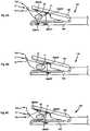
- jaw members 140are shown with various configurations of flexible member attachment structures 300, in accordance with embodiments of the present disclosure.
- the embodiment illustrated in Figure 6Aincludes anvil assembly 160 having proximal and distal flexible member attachment structures 300 AP and 300 AD , respectively, and cartridge assembly 150 having proximal and distal flexible member attachment structures 300 CP and 300 CD , respectively.
- the embodiment illustrated in Figure 6Bincludes anvil assembly 160 having a proximal flexible member attachment structure 300 AP , and cartridge assembly 150 having a proximal flexible member attachment structure 300 CP .
- FIG. 6Cincludes anvil assembly 160 having proximal and distal flexible member attachment structures 300 AP and 300 AD , respectively, and cartridge assembly 150 having a proximal flexible member attachment structure 300 CP .
- FIGS 6A - 6Calso illustrates flexible member "S" encircling target tissue "T,” with the second free end “F2" disposed through the loop "L" adjacent the first free end "F1.”
- the quantity and locations of flexible member attachment structures 300are not limited by the illustrated embodiments, as one skilled in the art can envision any number of flexible member attachment structures 300 disposed anywhere on loading unit 200.
- flexible member "S”is pre-tied onto jaw members 140 to allow the user to pull one end of flexible member "S” to capture tissue.
- the flexible membercan form a slip knot and a loop of the flexible member can extend around the jaw member of the instrument.
- a separate instrument(not explicitly shown in the illustrated embodiments), either separate from surgical instrument 100, attachable to surgical instrument 100, or integrally formed with surgical instrument 100, can be used to thread flexible member "S" through flexible member attachment structure(s) 300, thread flexible member “S” through loop “L,” rotate flexible member “S” around target tissue “T,” and/or pull flexible member “S” to cinch down on and constrict target tissue “T.”
- Such an instrumentmay be attachable to handle portion 110 of surgical instrument 100 and may include a separate actuation mechanism to longitudinally advance and/or rotate a distal portion of the instrument.
- a graspercan be used to manipulate the flexible member.
- a tissue clampcan be used to manipulate the flexible member or assist in clamping the tissue to facilitate the washout procedure. Suitable graspers and clamps are disclosed in U.S. Patent Application Serial Nos. 12/414,918 and 12/467,324 .
Landscapes
- Health & Medical Sciences (AREA)
- Life Sciences & Earth Sciences (AREA)
- Surgery (AREA)
- Molecular Biology (AREA)
- Engineering & Computer Science (AREA)
- Biomedical Technology (AREA)
- Heart & Thoracic Surgery (AREA)
- Medical Informatics (AREA)
- Nuclear Medicine, Radiotherapy & Molecular Imaging (AREA)
- Animal Behavior & Ethology (AREA)
- General Health & Medical Sciences (AREA)
- Public Health (AREA)
- Veterinary Medicine (AREA)
- Reproductive Health (AREA)
- Vascular Medicine (AREA)
- Surgical Instruments (AREA)
Description
- The present disclosure relates generally to instruments for surgically joining tissue and, more specifically, to a surgical instrument including flexible member attachment structures.
- Various types of surgical instruments used to surgically join tissue are known in the art, and are commonly used, for example, for closure of tissue or organs in transection, resection, anastomoses, for occlusion of organs in thoracic and abdominal procedures, and for electrosurgically fusing or sealing tissue.
- One example of such a surgical instrument is a surgical stapling instrument, which may include an anvil assembly, a cartridge assembly for supporting an array of surgical staples, an approximation mechanism for approximating the cartridge and anvil assemblies, and a firing mechanism for ejecting the surgical staples from the cartridge assembly.
- Using a surgical stapling instrument, it is common for a surgeon to approximate the anvil and cartridge members. Next, the surgeon can fire the instrument to emplace staples in tissue. Additionally, the surgeon may use the same instrument or a separate instrument to cut the tissue adjacent or between the row(s) of staples.
- Other examples of a surgical instrument of the present disclosure include electrosurgical (e.g., monopolar and bipolar) forceps. Electrosurgical forceps utilize both mechanical clamping action and electrical energy to affect hemostasis by heating the tissue and blood vessels to coagulate, cauterize and/or seal tissue.
- Examples of known instruments with different approaches to flexible member attachment are described in
U.S. Patent No. 5,318,579 ,U.S. Patent No. 2007/0114261 A1 , European Patent No.0799602 A1 andU.S. Patent No. 5,690,269 . - According to the invention there is provided a surgical instrument as recited in
claim 1 with preferred features as set forth in the dependent claims. - Various embodiments of the presently disclosed surgical instrument are disclosed herein with reference to the drawings, wherein:
Figure 1A is a perspective view of a surgical stapling instrument having linear jaw members in accordance with the present disclosure;Figure 1B is a perspective view a surgical stapling instrument having curved jaw members in accordance with the present disclosure;Figure 1C is a perspective view of an electrosurgical forceps in accordance with the present disclosure;Figures 2 - 3 are perspective views of a loading unit including two distally-disposed flexible member attachment structures with the jaw members open and closed, respectively, for use with the surgical instruments ofFigures 1A - 1C ;Figure 3A is a perspective view of a loading unit including cam bar and pushers in accordance with an embodiment of the present disclosure;- Figure 38 is an exploded perspective view of a loading unit in accordance with an embodiment of the present disclosure;
Figures 4A - 4E illustrate various types of flexible member attachment structures in accordance with the present disclosure;Figures 5A - 5C are perspective views of jaw members of a surgical instrument including two distally-disposed flexible member attachment structures in accordance with embodiments of the present disclosure illustrated during the process of encircling target tissue with flexible member; andFigures 6A - 6C are schematic side views of the jaw members showing flexible member attachment structures at various locations, and illustrating flexible member encircling target tissue.- Embodiments of the presently disclosed surgical instrument, and loading unit for use therewith, are described in detail with reference to the drawings, wherein like reference numerals designate corresponding elements in each of the several views.
- A surgical stapling instrument having linear jaw members of the present disclosure is indicated as reference numeral 100a in
Figure 1A . A surgical stapling instrument having curved jaw members of the present disclosure is indicated as reference numeral 100b inFigure 1B . An electrosurgical forceps of the present disclosure is indicated as reference numeral 100c inFigure 1C . Collectively, surgical instruments 100a, 100b and 100c are referred to herein asreference numeral 100. Similarly, several features that are common to each surgical stapling instrument 100a, 100b and 100c are collectively referred to as the same reference number. - With particular reference to
Figure. 1A , linear surgical stapling apparatus 100a includes ahandle assembly 110, anendoscopic portion 120, and anend effector 130 including a pair ofjaw members 140. Theend effector 130 may be positioned within a body cavity to engage tissue at a surgical site whilehandle assembly 110 is manipulatable by a surgeon from outside the body cavity to control the movement and operation of theend effector 130.Endoscopic portion 120 defines a longitudinal axis "A-A." - Jaw
members 140 ofend effector 130 include acartridge assembly 150, which houses a plurality of staples arranged in linear rows, and ananvil assembly 160 for forming the staples. At least one of thecartridge assembly 150 and theanvil assembly 160 is movable with respect to the other between an open position (Figure 2 shows curved jaw members in an open position) wherein thecartridge assembly 150 is substantially spaced from theanvil assembly 160 and an approximated position (Figure 3 shows curved jaw members in an approximated position) where thecartridge assembly 150 and theanvil assembly 160 are closer together. Amovable handle 112 of thehandle assembly 110 is movable through an actuation stroke or strokes relative to astationary handle 114 to move at least one of the jaw members 140 (e.g., cartridge assembly 150) in relation to the other jaw member (e.g., anvil assembly 160) between the open position and the approximated position and to eject the staples from thecartridge assembly 150 towards staple-forming pockets of theanvil assembly 160. - Further details of a linear surgical stapling instrument are described in detail in commonly-owned
U.S. Patent No. 6,953,139 to Milliman et al. - With reference to
Figure 1B , surgical stapling apparatus 100b havingcurved jaw members 140 is shown. Surgical stapling apparatus 100b and linear surgical stapling apparatus 100a share various common features. A distinguishing feature of surgical stapling apparatus 100b includes its curved jaw members 140b. Surgical stapling apparatus 100b include anend effector 130 having acartridge assembly 150 and ananvil assembly 160, that are each curved with respect to a longitudinal axis "A-A," defined byendoscopic portion 120. It is envisioned that the curved jaw members facilitate performing certain types of surgical procedures. For example, curved jaw members, as compared to linear jaw members (such as the jaw members illustrated inFigure 1A ), may help facilitate access to lower pelvic regions, e.g., during lower anterior resection ("LAR") or other colo-rectal surgery. Additionally, the inclusion ofcurved jaw members 140 may allow increased visualization to a surgical site and may also allow more room for a surgeon to manipulate target tissue or the jaw members 140b themselves with his or her hand. - In a surgical stapling instrument 100a, 100b in accordance with the present disclosure, a rod or other member is moved distally, through operation of
movable handle 112, toapproximate jaw members 140 and deploy the staples. For example, at least a partial actuation ofmovable handle 112 with respectstationary handle 114 translates a drive beam (not explicitly shown in the illustrated embodiments) longitudinally to approximate at least one jaw member with respect to the other. Additionally, at least a partial actuation (e.g., continued actuation) ofmovable handle 112 translates a firing rod (not explicitly shown in the illustrated embodiments) longitudinally to eject surgical fasteners (e.g., staples) fromcartridge assembly 150 and/or to advance a knife to cut tissue. It is also envisioned that actuation of a first handle approximates the jaw members with respect to one another and actuation of a second handle and/or a third handle causes the ejection of fasteners and advancement of the knife. Other types of handles can be used such as, for example, motor-driven, hydraulic, ratcheting, etc. - With continued reference to
Figure 1A , alever 170 is shown adjacent arotation dial 180 and may be used to facilitate articulation of thejaw members 140. Actuation oflever 170 causes thejaw members 140 to move between a first position, where thejaw members 140 are substantially aligned with the longitudinal axis "A-A," and a second position, where thejaw members 140 are disposed at an angle with respect to the longitudinal axis "A-A." It is envisioned that theendoscopic portion 120 includes at least one articulation link (not explicitly shown) at least partially therein, and that a proximal portion of the articulation link is mechanically engaged withlever 170, and that a distal portion of the articulation link is mechanically engaged with at least onejaw member 140. It is further envisioned that the distal portion of the articulation link is engaged with a lateral side of one of thejaw members 140, such that, movinglever 170 which causes the articulation link to move longitudinally, results in a proximal portion of at least one jaw member moving proximally or distally. That is, moving thelever 170 in a first direction causes the articulation link to move proximally (which articulates thejaw members 140 in a first direction) and moving thelever 170 in a second, opposite direction causes the articulation link to move distally (which articulates thejaw members 140 in a second direction). - Referring now to
Figure 1C , electrosurgical forceps 100c may also embody various aspects of the present disclosure. Electrosurgical forceps 100c includes aconnector assembly 102 for connection to a source of electrosurgical energy (not shown). Electrosurgical forceps 100c includes ahandle assembly 110 near a proximal end, anend effector 130 near a distal end, and anendoscopic portion 120 therebetween. Theend effector 130 may be positioned within a body cavity to engage tissue at a surgical site whilehandle assembly 110 is manipulatable by a surgeon from outside the body cavity to control the movement and operation of theend effector 130.Handle assembly 110 includes amovable handle 112, which may be manipulated to open and closejaw members 140 ofend effector 130, and atrigger 116, which may be manipulated to initiate an electrosurgical current. Further details of an electrosurgical forceps are described inU.S. Patent No. 7,083,618 . - A single use loading unit ("SULU") or a disposable loading unit ("DLU") (collectively referred to as "loading unit 200"), which is mechanically engageable with
handle portion 110 is shown inFigures 2-3 havingcurved jaw members 140. Loading unit 200 is attachable to anendoscopic portion 120 ofsurgical instrument 100, e.g., to allowsurgical stapling instrument 100 to have greater versatility. Loading unit 200 may be configured for a single use, and/or may be configured to be used more than once. Loading unit 200 includes a proximal body portion 210 and a tool assembly 220, which includesjaw members 140.Jaw members 140 of loading unit 200 include acartridge assembly 150, and ananvil assembly 160. Loading unit also includes an actuation mechanism for affecting movement of at least one of thecartridge assembly 150 and theanvil assembly 160 relative to the other, and for ejecting fasteners from thecartridge assembly 150. Proximal body portion 210 is configured to removably attach toendoscopic portion 120 ofsurgical instrument 100 using a variety of attachment features, such as, for example, a bayonet coupling, latch, detent or snap-fit. Examples of loading units for use with a surgical instrument are disclosed in commonly-owned United States Patent No.5,752,644 to Bolanos et al. - As illustrated in
Figure 3A , an embodiment of loading unit 200 includes a plurality of cam bars 131 for interacting withpushers 600 to deploysurgical fasteners 138. In the illustrated embodiment,pusher 600 includes threebody portions surgical fastener 138. Moreover, the apparatus disclosed inU.S. Patent No. 5,318,221 has a cam bar adapter that holds a plurality of cam bars and a knife. A channel is advanced through operation of the handle of the apparatus, which drives the cam bars and knife forward. A clamp tube that surrounds the proximal end of the anvil is advanced to clamp the anvil and cartridge together. - As shown in Figure 38, an embodiment of loading unit 200 includes a drive assembly 161 having an
elongated drive beam 162 that is advanced distally upon actuation ofmovable handle 112. The distal end of thedrive beam 162 engagesanvil assembly 160 and thechannel 113 that supportscartridge assembly 150 as thedrive beam 162 travels distally. Upon distal translation, thedrive beam 162 engagespushers 134 which deploy the staples 132 from staple-retaining slots 146, and clampsanvil assembly 160 andcartridge assembly 150 together. The apparatus disclosed inU.S. Patent No. 5,782,396 discloses additional details of this embodiment. - Referring now to
Figures 2 and3 , loading unit 200 is illustrated having flexiblemember attachment structures 300. Specifically, in thisembodiment cartridge assembly 150 includes a first flexiblemember attachment structure 300CD disposed on a distal portion of loading unit 200, andanvil assembly 160 includes a second flexiblemember attachment structure 300AD disposed on a distal portion of loading unit 200. As shown, flexiblemember attachment structures 300 are disposed on an inner portion of the curve ofjaw members 140. It is also envisioned that flexiblemember attachment structures 300 are disposed along an outer portion of the curve, or a combination of the inner and outer portions. With respect tolinear jaw members 140, such as thejaw members 140 illustrated inFigure 1A , it is envisioned that flexiblemember attachment structures 300 are disposed along either lateral side ofjaw members 140. It is also envisioned that flexiblemember attachment structures 300 extend upwardly from the upper jaw member (e.g., anvil assembly 160) and/or downwardly from the lower jaw member (e.g., cartridge assembly 150). Additionally, while flexiblemember attachment structures member attachment structures 300 of the present disclosure are vertically out of alignment. As discussed herein, flexiblemember attachment structures 300 are configured to facilitate attaching a flexible member "S" (seeFigures 4 - 6 ) to various portions of tool assembly 220 of loading unit 200. It is envisioned that flexible member "S" includes at least one of a suture, strap, cord, and the like. - Flexible
member attachment structures 300 are shown inFigures 2 and3 as hook-like members protruding from a lateral side of therespective jaw members 140. It is envisioned and within the scope of the present disclosure that flexiblemember attachment structures 300 are integrally formed with aparticular jaw member 140, or otherwise extend therefrom. Examples of flexiblemember attachment structures 300 in accordance with the present disclosure are illustrated inFigures 4A - 4D . In particular, flexiblemember attachment structure 300a inFigure 4A includes two arms with an opening therebetween, such that a flexible member "S" can be squeezed therein and therefrom. InFigure 4B , flexiblemember attachment structure 300b includes two flexible arms. InFigure 4C , flexiblemember attachment structure 300c includes a closed loop. InFigure 4D , flexible member attachment structure 300d includes a single arm and an opening. InFigure 4E , flexible member attachment structure 300e is integrally formed with ajaw member 140 and includes a channel for threading a flexible member "S" therethrough. In each of the embodiments disclosed herein, flexiblemember attachment structures 300 may be removable fromjaw members 140, or may be permanently attached thereto. As can be appreciated, many different other types of flexible member attachment structures are contemplated by the present disclosure. - Additionally, it is envisioned that flexible member "S" can be removably attached to
jaw members 140 by a temporary attachment structure, such as glue, tape, etc. Further, at least one flexiblemember attachment structure 300 may include a strap having a connection feature (e.g., a hook and loop fastener commonly sold under the trademark VELCRO) to quickly capture tissue. In such an embodiment, the use of a flexible member "S" may not be needed. - Referring now to
Figures 5A - 5C , the utilization of flexiblemember attachment structures 300 is shown according to embodiments of the present disclosure. Flexiblemember attachment structures 300 are configured for use with a flexible member "S" to encircle target tissue (e.g., a patient's bowel) prior to sealing the tissue. After the tissue is encircled, a surgeon may perform a washout procedure, e.g., to effectively remove cells (e.g., malignant cells) from the tissue (e.g., bowel). A washout procedure is when a surgeon flushes the tissue that will be placed between the jaws of thesurgical instrument 100 and fastened. The flexible member that is wrapped around the tissue may be used to control the flow of the fluid used in the washout procedure. A surgical procedure (e.g., a lower anterior resection) may then be performed after the washout procedure. Alternatively, if a physician chooses not to utilize flexiblemember attachment structures 300 and chooses not to perform a washout procedure, surgical instrument 100 (including flexible member attachment structures 300) may still be used to perform a suitable surgical procedure. That is, flexiblemember attachment structures 300 do not interfere with the typical use of asurgical instrument 100. - With continued reference to
Figures 5A - 5C , flexible member "S" is initially threaded through flexiblemember attachment structure 300AD and then through flexiblemember attachment structure 300PD. A loop "L" is created adjacent a first free end "F1" of the flexible member "S." Additionally, the flexible member "S" may be wrapped around or tied to a flexible member attachment structure (e.g., 300AD). The distal end ofjaw members 140 is then placed adjacent target tissue "T" (Figure 5A ).Jaw members 140 are then moved towards and into contact with the target tissue "T," which causes a second free end "F2" of the flexible member "S" to move relative to flexiblemember attachment structure 300CD. As a result, the flexible member "S" is pulled proximally within jaw members 140 (Figure 5B ). Next, the second free end "F2" of the flexible member is threaded through the loop "L" adjacent the first free end "F1" (Figure 5C ), thus encircling the target tissue "T." Finally, the second free end "F2" is pulled in the substantial direction of arrow "P" (Figure 5C ) to cinch down on and constrict the target tissue "T." After the target tissue "T" is constricted, the surgeon may perform a washout procedure. - With reference to
Figures 6A - 6C ,jaw members 140 are shown with various configurations of flexiblemember attachment structures 300, in accordance with embodiments of the present disclosure. In particular, the embodiment illustrated inFigure 6A includesanvil assembly 160 having proximal and distal flexiblemember attachment structures cartridge assembly 150 having proximal and distal flexiblemember attachment structures Figure 6B includesanvil assembly 160 having a proximal flexiblemember attachment structure 300AP, andcartridge assembly 150 having a proximal flexiblemember attachment structure 300CP. The embodiment illustrated inFigure 6C includesanvil assembly 160 having proximal and distal flexiblemember attachment structures cartridge assembly 150 having a proximal flexiblemember attachment structure 300CP. Each ofFigures 6A - 6C also illustrates flexible member "S" encircling target tissue "T," with the second free end "F2" disposed through the loop "L" adjacent the first free end "F1." As can be appreciated, the quantity and locations of flexiblemember attachment structures 300 are not limited by the illustrated embodiments, as one skilled in the art can envision any number of flexiblemember attachment structures 300 disposed anywhere on loading unit 200. - Additionally, while not explicitly illustrated in the accompanying figures, it is also envisioned that flexible member "S" is pre-tied onto
jaw members 140 to allow the user to pull one end of flexible member "S" to capture tissue. For example, the flexible member can form a slip knot and a loop of the flexible member can extend around the jaw member of the instrument. - In another embodiment of the present disclosure, a separate instrument (not explicitly shown in the illustrated embodiments), either separate from
surgical instrument 100, attachable tosurgical instrument 100, or integrally formed withsurgical instrument 100, can be used to thread flexible member "S" through flexible member attachment structure(s) 300, thread flexible member "S" through loop "L," rotate flexible member "S" around target tissue "T," and/or pull flexible member "S" to cinch down on and constrict target tissue "T." Such an instrument may be attachable to handleportion 110 ofsurgical instrument 100 and may include a separate actuation mechanism to longitudinally advance and/or rotate a distal portion of the instrument. It is envisioned that a grasper can be used to manipulate the flexible member. Additionally, a tissue clamp can be used to manipulate the flexible member or assist in clamping the tissue to facilitate the washout procedure. Suitable graspers and clamps are disclosed inU.S. Patent Application Serial Nos. 12/414,918 and12/467,324 - While the above description contains many specifics, these specifics should not be construed as limitations on the scope of the present disclosure, but merely as illustrations of various embodiments thereof. Therefore, the above description should not be construed as limiting, but merely as exemplifications of various embodiments. Those skilled in the art will envision other modifications within the scope of the claims appended hereto.
Claims (11)
- A surgical instrument for surgically joining tissue, the surgical instrument comprising:a handle portion (110);an endoscopic portion (120) extending distally from the handle portion (110) and defining a first longitudinal axis;a pair of jaw members (140) disposed adjacent a distal end of the endoscopic portion (120)and extending generally distally therefrom, at least one of the jaw members (140) being movable with respect to the other between an open position and an approximated position for engaging body tissue therebetween; andat least one flexible member attachment structure (300) disposed in mechanical cooperation with at least one jaw member (140),characterised in that, wherein a first jaw member (140) includes a first flexible member attachment structure (300AD, 300AP) and a second jaw member (140) includes a second flexible member attachment structure (300CD, 300CP), the first flexible member attachment structure (300AD, 300Ap) and second flexible member attachment structure (300CD, 300CP) protruding from a lateral side of the respective jaw member (140), the flexible member attachment structure (300) being configured to facilitate the releasable attachment of a flexible member (S) thereto.
- The surgical instrument of Claim 1, wherein the jaw members (140) are curved with respect to the first longitudinal axis.
- The surgical instrument of Claim 2, wherein the flexible member attachment structure (300) is disposed along an inner portion of the curve of at least one jaw member.
- The surgical instrument of Claim 4, wherein each of the first flexible member attachment structure (300) and the second flexible member attachment structure (300) are disposed on a portion of their respective jaw members (140) proximal to the endoscopic portion (120).
- The surgical instrument of Claim 4, wherein each of the first flexible member attachment structure (300) and the second flexible member attachment structure (300) are disposed on a portion of their respective jaw members (140) distal from the endoscopic portion (120).
- The surgical instrument of any preceding Claim, wherein each jaw member includes a first flexible member attachment structure (300) and a second flexible member attachment structure (300).
- The surgical instrument of any preceding Claim, wherein the flexible member attachment structure (300) is at least one of a channel formed in the jaw member, and a hook protruding from the jaw member.
- A loading unit configured for releasable engagement with a surgical instrument, the loading unit comprising:a body portion (210) defining a first longitudinal axis, a proximal portion of the body portion (210) configured for releasable engagement with an endoscopic portion (120)of the surgical instrument;a pair of jaw members (140) disposed distally of the body portion (210), at least one of the jaw members (140) being movable with respect to the other between an open position and an approximated position for engaging body tissue therebetween; andat least one flexible member attachment structure (300) disposed in mechanical cooperation with at least one jaw member (140), chracterised in that, a first jaw member (140) includes a first flexible member attachment structure (300AD, 300AP) and a second jaw member (140) includes a second flexible member attachment structure (300CD, 300CP), the first flexible member attachment structure (300AD, 300AP) and second flexible member attachment structure (300CD, 300CP) protruding from a lateral side of the respective jaw member (140), the flexible member attachment structure (300) being configured to facilitate the releasable attachment of a flexible member thereto.
- The loading unit of Claim 8, wherein the jaw members (140) are curved with respect to the first longitudinal axis.
- The loading unit of Claim 8 or Claim 9, wherein the flexible member attachment structure (300) is disposed along an inner portion of the curve of at least one jaw member (140).
- The loading unit of any of Claims 8 to 10, wherein the flexible member attachment structure (300) is at least one of a channel formed in the jaw member, and a hook protruding from the jaw member (140).
Applications Claiming Priority (1)
| Application Number | Priority Date | Filing Date | Title |
|---|---|---|---|
| US12/778,487US8940000B2 (en) | 2010-05-12 | 2010-05-12 | Surgical instruments with flexible member attachment structures |
Publications (3)
| Publication Number | Publication Date |
|---|---|
| EP2386253A2 EP2386253A2 (en) | 2011-11-16 |
| EP2386253A3 EP2386253A3 (en) | 2015-05-06 |
| EP2386253B1true EP2386253B1 (en) | 2018-10-10 |
Family
ID=44453993
Family Applications (1)
| Application Number | Title | Priority Date | Filing Date |
|---|---|---|---|
| EP11250518.5ANot-in-forceEP2386253B1 (en) | 2010-05-12 | 2011-05-11 | Surgical instrument with flexible member attachment structures |
Country Status (4)
| Country | Link |
|---|---|
| US (1) | US8940000B2 (en) |
| EP (1) | EP2386253B1 (en) |
| AU (1) | AU2011201491A1 (en) |
| CA (1) | CA2735506A1 (en) |
Families Citing this family (20)
| Publication number | Priority date | Publication date | Assignee | Title |
|---|---|---|---|---|
| US9724095B2 (en)* | 2011-08-08 | 2017-08-08 | Covidien Lp | Surgical fastener applying apparatus |
| US12343027B2 (en) | 2012-02-22 | 2025-07-01 | Carter J. Kovarik | Medical instruments for performing a minimally-invasive procedure |
| US9592066B2 (en) | 2012-02-22 | 2017-03-14 | Carter J. Kovarik | Selectively bendable remote gripping tool |
| US9095127B2 (en) | 2012-02-22 | 2015-08-04 | Carter J. Kovarik | Selectively bendable remote gripping tool |
| US11083475B2 (en) | 2012-02-22 | 2021-08-10 | Carter J. Kovarik | Medical device to remove an obstruction from a body lumen, vessel or organ |
| US9832980B2 (en) | 2012-02-22 | 2017-12-05 | Carter J. Kovarik | Selectively bendable remote gripping tool |
| US10226266B2 (en) | 2012-02-22 | 2019-03-12 | Carter J. Kovarik | Selectively bendable remote gripping tool |
| US9901245B2 (en) | 2012-02-22 | 2018-02-27 | Carter J. Kovarik | Selectively bendable remote gripping tool |
| USD780547S1 (en) | 2013-08-08 | 2017-03-07 | Carter J. Kovarik | Pick up device with flexible shaft portion |
| US20150257756A1 (en)* | 2014-03-13 | 2015-09-17 | Lsi Solutions, Inc. | Surgical clamping device and methods thereof |
| US10342535B2 (en) | 2015-10-15 | 2019-07-09 | Ethicon Llc | Method of applying staples to liver and other organs |
| US10265069B2 (en) | 2015-10-15 | 2019-04-23 | Ethicon Llc | Surgical staple cartridge with varying staple crown width along a curve |
| US11141159B2 (en) | 2015-10-15 | 2021-10-12 | Cilag Gmbh International | Surgical stapler end effector with multi-staple driver crossing center line |
| US10226251B2 (en) | 2015-10-15 | 2019-03-12 | Ethicon Llc | Surgical staple actuating sled with actuation stroke having minimized distance relative to distal staple |
| US10499917B2 (en) | 2015-10-15 | 2019-12-10 | Ethicon Llc | Surgical stapler end effector with knife position indicators |
| US10952730B2 (en)* | 2015-10-15 | 2021-03-23 | Ethicon Llc | End effector for surgical stapler with varying curve and taper |
| US10265073B2 (en) | 2015-10-15 | 2019-04-23 | Ethicon Llc | Surgical stapler with terminal staple orientation crossing center line |
| WO2018027788A1 (en)* | 2016-08-11 | 2018-02-15 | Covidien Lp | Endoscopic surgical clip applier and clip applying systems |
| US10912562B2 (en)* | 2017-08-14 | 2021-02-09 | Standard Bariatrics, Inc. | End effectors, surgical stapling devices, and methods of using same |
| CN112426196B (en)* | 2020-10-15 | 2021-10-01 | 中国人民解放军陆军军医大学第一附属医院 | Thyroid gland postoperative oppression fixing device |
Family Cites Families (73)
| Publication number | Priority date | Publication date | Assignee | Title |
|---|---|---|---|---|
| US3017637A (en) | 1959-07-10 | 1962-01-23 | Sampson Arnold | Surgical suturing instrument |
| US3269630A (en) | 1964-04-30 | 1966-08-30 | Fleischer Harry | Stapling instrument |
| US3315863A (en) | 1965-07-06 | 1967-04-25 | United States Surgical Corp | Medical instrument |
| US3842840A (en) | 1973-05-07 | 1974-10-22 | E Schweizer | Suture applicator |
| CH635505A5 (en) | 1978-08-28 | 1983-04-15 | Vnii Ispytatel Med Tech | Surgical suturing device for suturing organs with metal clips |
| US4216891A (en) | 1979-02-12 | 1980-08-12 | Behlke Harold O | Surgical stapler |
| SU942719A1 (en) | 1979-11-23 | 1982-07-15 | Всесоюзный научно-исследовательский и испытательный институт медицинской техники | Surgical suturing apparatus for application of linear sutures |
| US4354628A (en) | 1980-09-29 | 1982-10-19 | United States Surgical Corporation | Surgical stapler apparatus having pivotally related staple holder and anvil |
| US4383634A (en) | 1981-05-26 | 1983-05-17 | United States Surgical Corporation | Surgical stapler apparatus with pivotally mounted actuator assemblies |
| US4506671A (en) | 1983-03-30 | 1985-03-26 | United States Surgical Corporation | Apparatus for applying two-part surgical fasteners |
| US4530453A (en) | 1983-10-04 | 1985-07-23 | United States Surgical Corporation | Surgical fastener applying apparatus |
| US4568009A (en) | 1984-01-20 | 1986-02-04 | United States Surgical Corporation | Surgical fastener applying apparatus |
| IN165375B (en) | 1984-07-16 | 1989-10-07 | Ethicon Inc | |
| US4589582A (en) | 1984-08-23 | 1986-05-20 | Senmed, Inc. | Cartridge and driver assembly for a surgical stapling instrument |
| US4617928A (en) | 1984-09-17 | 1986-10-21 | Alfranca Jose Maria P | Surgical instrument for practicing mechanical sutures and biopsies |
| US4566620A (en) | 1984-10-19 | 1986-01-28 | United States Surgical Corporation | Articulated surgical fastener applying apparatus |
| US4665916A (en) | 1985-08-09 | 1987-05-19 | United States Surgical Corporation | Surgical stapler apparatus |
| US4728020A (en) | 1985-08-30 | 1988-03-01 | United States Surgical Corporation | Articulated surgical fastener applying apparatus |
| CH670753A5 (en) | 1985-09-10 | 1989-07-14 | Vnii Ispytatel Med Tech | |
| US4715520A (en) | 1985-10-10 | 1987-12-29 | United States Surgical Corporation | Surgical fastener applying apparatus with tissue edge control |
| US4819853A (en) | 1987-12-31 | 1989-04-11 | United States Surgical Corporation | Surgical fastener cartridge |
| US4881545A (en) | 1988-12-08 | 1989-11-21 | United States Surgical Corporation | Surgical fastener cartridge with improved body tissue cutting knife assembly |
| US4881544A (en) | 1988-12-19 | 1989-11-21 | United States Surgical Corporation | Surgical stapler apparatus with improved tissue shield |
| US4915100A (en) | 1988-12-19 | 1990-04-10 | United States Surgical Corporation | Surgical stapler apparatus with tissue shield |
| US5318221A (en) | 1989-05-26 | 1994-06-07 | United States Surgical Corporation | Apparatus and method for placing staples in laparoscopic or endoscopic procedures |
| US5100042A (en) | 1990-03-05 | 1992-03-31 | United States Surgical Corporation | Surgical fastener apparatus |
| CA2079756A1 (en) | 1991-10-18 | 1993-04-19 | David T. Green | Apparatus for applying surgical fasteners |
| AU660712B2 (en) | 1991-10-18 | 1995-07-06 | United States Surgical Corporation | Apparatus for applying surgical fasteners |
| US5579978A (en) | 1991-10-18 | 1996-12-03 | United States Surgical Corporation | Apparatus for applying surgical fasteners |
| US5425737A (en)* | 1992-04-08 | 1995-06-20 | American Cyanamid Co. | Surgical purse string suturing instrument and method |
| US5318579A (en)* | 1992-09-21 | 1994-06-07 | Chow James C Y | Arthroscopic knot tying device |
| US5423471A (en) | 1992-10-02 | 1995-06-13 | United States Surgical Corporation | Apparatus for applying two-part surgical fasteners in laparoscopic or endoscopic procedures |
| US5540375A (en)* | 1993-04-20 | 1996-07-30 | United States Surgical Corporation | Endoscopic stapler |
| US5405073A (en) | 1993-12-06 | 1995-04-11 | Ethicon, Inc. | Flexible support shaft assembly |
| US5465894A (en) | 1993-12-06 | 1995-11-14 | Ethicon, Inc. | Surgical stapling instrument with articulated stapling head assembly on rotatable and flexible support shaft |
| US5470008A (en) | 1993-12-20 | 1995-11-28 | United States Surgical Corporation | Apparatus for applying surgical fasteners |
| US5452836A (en) | 1994-02-07 | 1995-09-26 | Ethicon Endo-Surgery, Inc. | Surgical stapling instrument with improved jaw closure and staple firing actuator mechanism |
| CA2145723A1 (en) | 1994-03-30 | 1995-10-01 | Steven W. Hamblin | Surgical stapling instrument with remotely articulated stapling head assembly on rotatable support shaft |
| US5489058A (en) | 1994-05-02 | 1996-02-06 | Minnesota Mining And Manufacturing Company | Surgical stapler with mechanisms for reducing the firing force |
| US5752644A (en) | 1995-07-11 | 1998-05-19 | United States Surgical Corporation | Disposable loading unit for surgical stapler |
| US5706998A (en) | 1995-07-17 | 1998-01-13 | United States Surgical Corporation | Surgical stapler with alignment pin locking mechanism |
| US5782396A (en) | 1995-08-28 | 1998-07-21 | United States Surgical Corporation | Surgical stapler |
| US5746757A (en)* | 1996-01-17 | 1998-05-05 | Mcguire; David A. | Suturing jig and method for using same |
| JP2873366B2 (en)* | 1996-04-01 | 1999-03-24 | ▼しずか▲ 加▼せ▲田 | Forceps |
| US6015428A (en) | 1997-06-03 | 2000-01-18 | Anthony C. Pagedas | Integrally formed suture and suture lock |
| US5843126A (en) | 1997-08-15 | 1998-12-01 | Jameel; Irfan M. | Multiple surgical suture application |
| US5865361A (en) | 1997-09-23 | 1999-02-02 | United States Surgical Corporation | Surgical stapling apparatus |
| US6217592B1 (en)* | 1998-10-06 | 2001-04-17 | Vincent Freda | Laproscopic instrument for suturing tissue |
| US6066160A (en) | 1998-11-23 | 2000-05-23 | Quickie Llc | Passive knotless suture terminator for use in minimally invasive surgery and to facilitate standard tissue securing |
| US7846180B2 (en) | 1999-06-22 | 2010-12-07 | Ethicon Endo-Surgery, Inc. | Tissue fixation devices and methods of fixing tissue |
| US6805273B2 (en) | 2002-11-04 | 2004-10-19 | Federico Bilotti | Surgical stapling instrument |
| US6817508B1 (en) | 2000-10-13 | 2004-11-16 | Tyco Healthcare Group, Lp | Surgical stapling device |
| US7083618B2 (en) | 2001-04-06 | 2006-08-01 | Sherwood Services Ag | Vessel sealer and divider |
| US6746456B2 (en) | 2001-09-28 | 2004-06-08 | Ethicon, Inc. | Needle array suturing/sewing anastomosis device and method for anastomosis |
| US7879046B2 (en) | 2001-10-01 | 2011-02-01 | Depuy Mitek, Inc. | Suturing apparatus and method |
| US7585305B2 (en) | 2002-05-15 | 2009-09-08 | Arthrex, Inc. | Suture passing instrument |
| AU2003277294A1 (en) | 2002-10-04 | 2004-05-04 | Tyco Healthcare Group, Lp | Angled surgical fastener apparatus |
| US7309342B2 (en) | 2003-01-16 | 2007-12-18 | Mark Genovesi | Heatless blood vessel harvesting device |
| US7207472B2 (en) | 2003-12-30 | 2007-04-24 | Ethicon Endo-Surgery, Inc. | Cartridge with locking knife for a curved cutter stapler |
| US6988650B2 (en) | 2003-12-30 | 2006-01-24 | Ethicon Endo-Surgery, Inc. | Retaining pin lever advancement mechanism for a curved cutter stapler |
| US20050145672A1 (en) | 2003-12-30 | 2005-07-07 | Schwemberger Richard F. | Curved cutter stapler with aligned tissue retention feature |
| US20050139636A1 (en) | 2003-12-30 | 2005-06-30 | Schwemberger Richard F. | Replaceable cartridge module for a surgical stapling and cutting instrument |
| US7147139B2 (en) | 2003-12-30 | 2006-12-12 | Ethicon Endo-Surgery, Inc | Closure plate lockout for a curved cutter stapler |
| US20050143759A1 (en) | 2003-12-30 | 2005-06-30 | Kelly William D. | Curved cutter stapler shaped for male pelvis |
| US7204404B2 (en) | 2003-12-30 | 2007-04-17 | Ethicon Endo-Surgery, Inc. | Slotted pins guiding knife in a curved cutter stapler |
| US7651017B2 (en)* | 2005-11-23 | 2010-01-26 | Ethicon Endo-Surgery, Inc. | Surgical stapler with a bendable end effector |
| US8734443B2 (en)* | 2006-01-24 | 2014-05-27 | Covidien Lp | Vessel sealer and divider for large tissue structures |
| US7572265B2 (en)* | 2006-03-21 | 2009-08-11 | Biomet Sports Medicine, Llc | Method and apparatus for passing a suture |
| US20090281563A1 (en) | 2006-04-19 | 2009-11-12 | Newell Matthew B | Devices, tools and methods for performing minimally invasive abdominal surgical procedures |
| US20070250118A1 (en) | 2006-04-20 | 2007-10-25 | Masini Michael A | Compression tissue repair apparatus and methods |
| US7506791B2 (en) | 2006-09-29 | 2009-03-24 | Ethicon Endo-Surgery, Inc. | Surgical stapling instrument with mechanical mechanism for limiting maximum tissue compression |
| US7997468B2 (en)* | 2008-05-05 | 2011-08-16 | Tyco Healthcare Group Lp | Surgical instrument with clamp |
| US8282656B2 (en)* | 2009-05-28 | 2012-10-09 | Karl Storz Gmbh & Co. Kg | Suture passing instrument |
- 2010
- 2010-05-12USUS12/778,487patent/US8940000B2/enactiveActive
- 2011
- 2011-03-28CACA2735506Apatent/CA2735506A1/ennot_activeAbandoned
- 2011-04-01AUAU2011201491Apatent/AU2011201491A1/ennot_activeAbandoned
- 2011-05-11EPEP11250518.5Apatent/EP2386253B1/ennot_activeNot-in-force
Non-Patent Citations (1)
| Title |
|---|
| None* |
Also Published As
| Publication number | Publication date |
|---|---|
| US8940000B2 (en) | 2015-01-27 |
| EP2386253A2 (en) | 2011-11-16 |
| US20110282363A1 (en) | 2011-11-17 |
| CA2735506A1 (en) | 2011-11-12 |
| EP2386253A3 (en) | 2015-05-06 |
| AU2011201491A1 (en) | 2011-12-01 |
Similar Documents
| Publication | Publication Date | Title |
|---|---|---|
| EP2386253B1 (en) | Surgical instrument with flexible member attachment structures | |
| EP2116193B1 (en) | Surgical instrument with clamp | |
| US10548594B2 (en) | Attachable clamp for use with surgical instruments | |
| JP6862436B2 (en) | Surgical staple actuating thread with actuation stroke having minimum distance to distal staple | |
| US9463021B2 (en) | Surgical instrument with pivotable jaw member | |
| JP6862438B2 (en) | Surgical stapler with gradually driven asymmetric alternating stapler driver | |
| CN108135606B (en) | Surgical stapler end effector with knife position indicator | |
| CN108135607B (en) | End effector with varying bend and taper for surgical stapler | |
| EP2685906B1 (en) | Surgical fastener instruments | |
| CN117243656A (en) | Surgical stapler end effector with multi-staple drivers across the centerline | |
| CN108348235B (en) | Surgical staple cartridge with varying crown width along the curve | |
| AU2014202519B2 (en) | Attachable clamp for use with surgical instruments |
Legal Events
| Date | Code | Title | Description |
|---|---|---|---|
| AK | Designated contracting states | Kind code of ref document:A2 Designated state(s):AL AT BE BG CH CY CZ DE DK EE ES FI FR GB GR HR HU IE IS IT LI LT LU LV MC MK MT NL NO PL PT RO RS SE SI SK SM TR | |
| AX | Request for extension of the european patent | Extension state:BA ME | |
| PUAI | Public reference made under article 153(3) epc to a published international application that has entered the european phase | Free format text:ORIGINAL CODE: 0009012 | |
| RAP1 | Party data changed (applicant data changed or rights of an application transferred) | Owner name:COVIDIEN LP | |
| PUAL | Search report despatched | Free format text:ORIGINAL CODE: 0009013 | |
| AK | Designated contracting states | Kind code of ref document:A3 Designated state(s):AL AT BE BG CH CY CZ DE DK EE ES FI FR GB GR HR HU IE IS IT LI LT LU LV MC MK MT NL NO PL PT RO RS SE SI SK SM TR | |
| AX | Request for extension of the european patent | Extension state:BA ME | |
| RIC1 | Information provided on ipc code assigned before grant | Ipc:A61B 17/12 20060101ALN20150327BHEP Ipc:A61B 18/14 20060101ALI20150327BHEP Ipc:A61B 17/29 20060101ALI20150327BHEP Ipc:A61B 17/072 20060101AFI20150327BHEP | |
| 17P | Request for examination filed | Effective date:20151102 | |
| RBV | Designated contracting states (corrected) | Designated state(s):AL AT BE BG CH CY CZ DE DK EE ES FI FR GB GR HR HU IE IS IT LI LT LU LV MC MK MT NL NO PL PT RO RS SE SI SK SM TR | |
| STAA | Information on the status of an ep patent application or granted ep patent | Free format text:STATUS: EXAMINATION IS IN PROGRESS | |
| 17Q | First examination report despatched | Effective date:20180102 | |
| GRAP | Despatch of communication of intention to grant a patent | Free format text:ORIGINAL CODE: EPIDOSNIGR1 | |
| STAA | Information on the status of an ep patent application or granted ep patent | Free format text:STATUS: GRANT OF PATENT IS INTENDED | |
| RIC1 | Information provided on ipc code assigned before grant | Ipc:A61B 17/12 20060101ALN20180509BHEP Ipc:A61B 17/29 20060101ALI20180509BHEP Ipc:A61B 18/14 20060101ALI20180509BHEP Ipc:A61B 17/072 20060101AFI20180509BHEP | |
| INTG | Intention to grant announced | Effective date:20180601 | |
| GRAS | Grant fee paid | Free format text:ORIGINAL CODE: EPIDOSNIGR3 | |
| GRAA | (expected) grant | Free format text:ORIGINAL CODE: 0009210 | |
| STAA | Information on the status of an ep patent application or granted ep patent | Free format text:STATUS: THE PATENT HAS BEEN GRANTED | |
| AK | Designated contracting states | Kind code of ref document:B1 Designated state(s):AL AT BE BG CH CY CZ DE DK EE ES FI FR GB GR HR HU IE IS IT LI LT LU LV MC MK MT NL NO PL PT RO RS SE SI SK SM TR | |
| REG | Reference to a national code | Ref country code:GB Ref legal event code:FG4D | |
| REG | Reference to a national code | Ref country code:CH Ref legal event code:EP Ref country code:AT Ref legal event code:REF Ref document number:1050309 Country of ref document:AT Kind code of ref document:T Effective date:20181015 | |
| REG | Reference to a national code | Ref country code:IE Ref legal event code:FG4D Ref country code:DE Ref legal event code:R096 Ref document number:602011052734 Country of ref document:DE | |
| REG | Reference to a national code | Ref country code:NL Ref legal event code:MP Effective date:20181010 | |
| REG | Reference to a national code | Ref country code:LT Ref legal event code:MG4D | |
| REG | Reference to a national code | Ref country code:AT Ref legal event code:MK05 Ref document number:1050309 Country of ref document:AT Kind code of ref document:T Effective date:20181010 | |
| PG25 | Lapsed in a contracting state [announced via postgrant information from national office to epo] | Ref country code:NL Free format text:LAPSE BECAUSE OF FAILURE TO SUBMIT A TRANSLATION OF THE DESCRIPTION OR TO PAY THE FEE WITHIN THE PRESCRIBED TIME-LIMIT Effective date:20181010 | |
| PG25 | Lapsed in a contracting state [announced via postgrant information from national office to epo] | Ref country code:LT Free format text:LAPSE BECAUSE OF FAILURE TO SUBMIT A TRANSLATION OF THE DESCRIPTION OR TO PAY THE FEE WITHIN THE PRESCRIBED TIME-LIMIT Effective date:20181010 Ref country code:NO Free format text:LAPSE BECAUSE OF FAILURE TO SUBMIT A TRANSLATION OF THE DESCRIPTION OR TO PAY THE FEE WITHIN THE PRESCRIBED TIME-LIMIT Effective date:20190110 Ref country code:FI Free format text:LAPSE BECAUSE OF FAILURE TO SUBMIT A TRANSLATION OF THE DESCRIPTION OR TO PAY THE FEE WITHIN THE PRESCRIBED TIME-LIMIT Effective date:20181010 Ref country code:IS Free format text:LAPSE BECAUSE OF FAILURE TO SUBMIT A TRANSLATION OF THE DESCRIPTION OR TO PAY THE FEE WITHIN THE PRESCRIBED TIME-LIMIT Effective date:20190210 Ref country code:LV Free format text:LAPSE BECAUSE OF FAILURE TO SUBMIT A TRANSLATION OF THE DESCRIPTION OR TO PAY THE FEE WITHIN THE PRESCRIBED TIME-LIMIT Effective date:20181010 Ref country code:ES Free format text:LAPSE BECAUSE OF FAILURE TO SUBMIT A TRANSLATION OF THE DESCRIPTION OR TO PAY THE FEE WITHIN THE PRESCRIBED TIME-LIMIT Effective date:20181010 Ref country code:BG Free format text:LAPSE BECAUSE OF FAILURE TO SUBMIT A TRANSLATION OF THE DESCRIPTION OR TO PAY THE FEE WITHIN THE PRESCRIBED TIME-LIMIT Effective date:20190110 Ref country code:HR Free format text:LAPSE BECAUSE OF FAILURE TO SUBMIT A TRANSLATION OF THE DESCRIPTION OR TO PAY THE FEE WITHIN THE PRESCRIBED TIME-LIMIT Effective date:20181010 Ref country code:PL Free format text:LAPSE BECAUSE OF FAILURE TO SUBMIT A TRANSLATION OF THE DESCRIPTION OR TO PAY THE FEE WITHIN THE PRESCRIBED TIME-LIMIT Effective date:20181010 Ref country code:AT Free format text:LAPSE BECAUSE OF FAILURE TO SUBMIT A TRANSLATION OF THE DESCRIPTION OR TO PAY THE FEE WITHIN THE PRESCRIBED TIME-LIMIT Effective date:20181010 | |
| PG25 | Lapsed in a contracting state [announced via postgrant information from national office to epo] | Ref country code:RS Free format text:LAPSE BECAUSE OF FAILURE TO SUBMIT A TRANSLATION OF THE DESCRIPTION OR TO PAY THE FEE WITHIN THE PRESCRIBED TIME-LIMIT Effective date:20181010 Ref country code:GR Free format text:LAPSE BECAUSE OF FAILURE TO SUBMIT A TRANSLATION OF THE DESCRIPTION OR TO PAY THE FEE WITHIN THE PRESCRIBED TIME-LIMIT Effective date:20190111 Ref country code:SE Free format text:LAPSE BECAUSE OF FAILURE TO SUBMIT A TRANSLATION OF THE DESCRIPTION OR TO PAY THE FEE WITHIN THE PRESCRIBED TIME-LIMIT Effective date:20181010 Ref country code:PT Free format text:LAPSE BECAUSE OF FAILURE TO SUBMIT A TRANSLATION OF THE DESCRIPTION OR TO PAY THE FEE WITHIN THE PRESCRIBED TIME-LIMIT Effective date:20190210 Ref country code:AL Free format text:LAPSE BECAUSE OF FAILURE TO SUBMIT A TRANSLATION OF THE DESCRIPTION OR TO PAY THE FEE WITHIN THE PRESCRIBED TIME-LIMIT Effective date:20181010 | |
| REG | Reference to a national code | Ref country code:DE Ref legal event code:R097 Ref document number:602011052734 Country of ref document:DE | |
| PG25 | Lapsed in a contracting state [announced via postgrant information from national office to epo] | Ref country code:DK Free format text:LAPSE BECAUSE OF FAILURE TO SUBMIT A TRANSLATION OF THE DESCRIPTION OR TO PAY THE FEE WITHIN THE PRESCRIBED TIME-LIMIT Effective date:20181010 Ref country code:IT Free format text:LAPSE BECAUSE OF FAILURE TO SUBMIT A TRANSLATION OF THE DESCRIPTION OR TO PAY THE FEE WITHIN THE PRESCRIBED TIME-LIMIT Effective date:20181010 Ref country code:CZ Free format text:LAPSE BECAUSE OF FAILURE TO SUBMIT A TRANSLATION OF THE DESCRIPTION OR TO PAY THE FEE WITHIN THE PRESCRIBED TIME-LIMIT Effective date:20181010 | |
| PLBE | No opposition filed within time limit | Free format text:ORIGINAL CODE: 0009261 | |
| STAA | Information on the status of an ep patent application or granted ep patent | Free format text:STATUS: NO OPPOSITION FILED WITHIN TIME LIMIT | |
| PG25 | Lapsed in a contracting state [announced via postgrant information from national office to epo] | Ref country code:SK Free format text:LAPSE BECAUSE OF FAILURE TO SUBMIT A TRANSLATION OF THE DESCRIPTION OR TO PAY THE FEE WITHIN THE PRESCRIBED TIME-LIMIT Effective date:20181010 Ref country code:RO Free format text:LAPSE BECAUSE OF FAILURE TO SUBMIT A TRANSLATION OF THE DESCRIPTION OR TO PAY THE FEE WITHIN THE PRESCRIBED TIME-LIMIT Effective date:20181010 Ref country code:SM Free format text:LAPSE BECAUSE OF FAILURE TO SUBMIT A TRANSLATION OF THE DESCRIPTION OR TO PAY THE FEE WITHIN THE PRESCRIBED TIME-LIMIT Effective date:20181010 Ref country code:EE Free format text:LAPSE BECAUSE OF FAILURE TO SUBMIT A TRANSLATION OF THE DESCRIPTION OR TO PAY THE FEE WITHIN THE PRESCRIBED TIME-LIMIT Effective date:20181010 | |
| 26N | No opposition filed | Effective date:20190711 | |
| PG25 | Lapsed in a contracting state [announced via postgrant information from national office to epo] | Ref country code:SI Free format text:LAPSE BECAUSE OF FAILURE TO SUBMIT A TRANSLATION OF THE DESCRIPTION OR TO PAY THE FEE WITHIN THE PRESCRIBED TIME-LIMIT Effective date:20181010 | |
| REG | Reference to a national code | Ref country code:DE Ref legal event code:R119 Ref document number:602011052734 Country of ref document:DE | |
| REG | Reference to a national code | Ref country code:CH Ref legal event code:PL | |
| GBPC | Gb: european patent ceased through non-payment of renewal fee | Effective date:20190511 | |
| PG25 | Lapsed in a contracting state [announced via postgrant information from national office to epo] | Ref country code:MC Free format text:LAPSE BECAUSE OF FAILURE TO SUBMIT A TRANSLATION OF THE DESCRIPTION OR TO PAY THE FEE WITHIN THE PRESCRIBED TIME-LIMIT Effective date:20181010 Ref country code:CH Free format text:LAPSE BECAUSE OF NON-PAYMENT OF DUE FEES Effective date:20190531 Ref country code:LI Free format text:LAPSE BECAUSE OF NON-PAYMENT OF DUE FEES Effective date:20190531 | |
| REG | Reference to a national code | Ref country code:BE Ref legal event code:MM Effective date:20190531 | |
| PG25 | Lapsed in a contracting state [announced via postgrant information from national office to epo] | Ref country code:LU Free format text:LAPSE BECAUSE OF NON-PAYMENT OF DUE FEES Effective date:20190511 | |
| PG25 | Lapsed in a contracting state [announced via postgrant information from national office to epo] | Ref country code:TR Free format text:LAPSE BECAUSE OF FAILURE TO SUBMIT A TRANSLATION OF THE DESCRIPTION OR TO PAY THE FEE WITHIN THE PRESCRIBED TIME-LIMIT Effective date:20181010 | |
| PG25 | Lapsed in a contracting state [announced via postgrant information from national office to epo] | Ref country code:IE Free format text:LAPSE BECAUSE OF NON-PAYMENT OF DUE FEES Effective date:20190511 Ref country code:DE Free format text:LAPSE BECAUSE OF NON-PAYMENT OF DUE FEES Effective date:20191203 Ref country code:GB Free format text:LAPSE BECAUSE OF NON-PAYMENT OF DUE FEES Effective date:20190511 | |
| PG25 | Lapsed in a contracting state [announced via postgrant information from national office to epo] | Ref country code:BE Free format text:LAPSE BECAUSE OF NON-PAYMENT OF DUE FEES Effective date:20190531 | |
| PG25 | Lapsed in a contracting state [announced via postgrant information from national office to epo] | Ref country code:FR Free format text:LAPSE BECAUSE OF NON-PAYMENT OF DUE FEES Effective date:20190531 | |
| PG25 | Lapsed in a contracting state [announced via postgrant information from national office to epo] | Ref country code:CY Free format text:LAPSE BECAUSE OF FAILURE TO SUBMIT A TRANSLATION OF THE DESCRIPTION OR TO PAY THE FEE WITHIN THE PRESCRIBED TIME-LIMIT Effective date:20181010 | |
| PG25 | Lapsed in a contracting state [announced via postgrant information from national office to epo] | Ref country code:HU Free format text:LAPSE BECAUSE OF FAILURE TO SUBMIT A TRANSLATION OF THE DESCRIPTION OR TO PAY THE FEE WITHIN THE PRESCRIBED TIME-LIMIT; INVALID AB INITIO Effective date:20110511 Ref country code:MT Free format text:LAPSE BECAUSE OF FAILURE TO SUBMIT A TRANSLATION OF THE DESCRIPTION OR TO PAY THE FEE WITHIN THE PRESCRIBED TIME-LIMIT Effective date:20181010 | |
| PG25 | Lapsed in a contracting state [announced via postgrant information from national office to epo] | Ref country code:MK Free format text:LAPSE BECAUSE OF FAILURE TO SUBMIT A TRANSLATION OF THE DESCRIPTION OR TO PAY THE FEE WITHIN THE PRESCRIBED TIME-LIMIT Effective date:20181010 |