EP2382831B1 - Correcting gps through secondary sensors and signal strength - Google Patents
Correcting gps through secondary sensors and signal strengthDownload PDFInfo
- Publication number
- EP2382831B1 EP2382831B1EP09836794.9AEP09836794AEP2382831B1EP 2382831 B1EP2382831 B1EP 2382831B1EP 09836794 AEP09836794 AEP 09836794AEP 2382831 B1EP2382831 B1EP 2382831B1
- Authority
- EP
- European Patent Office
- Prior art keywords
- mobile unit
- computer
- motion
- signal strength
- gps
- Prior art date
- Legal status (The legal status is an assumption and is not a legal conclusion. Google has not performed a legal analysis and makes no representation as to the accuracy of the status listed.)
- Active
Links
Images


Classifications
- G—PHYSICS
- G01—MEASURING; TESTING
- G01S—RADIO DIRECTION-FINDING; RADIO NAVIGATION; DETERMINING DISTANCE OR VELOCITY BY USE OF RADIO WAVES; LOCATING OR PRESENCE-DETECTING BY USE OF THE REFLECTION OR RERADIATION OF RADIO WAVES; ANALOGOUS ARRANGEMENTS USING OTHER WAVES
- G01S19/00—Satellite radio beacon positioning systems; Determining position, velocity or attitude using signals transmitted by such systems
- G01S19/01—Satellite radio beacon positioning systems transmitting time-stamped messages, e.g. GPS [Global Positioning System], GLONASS [Global Orbiting Navigation Satellite System] or GALILEO
- G01S19/13—Receivers
- G01S19/23—Testing, monitoring, correcting or calibrating of receiver elements
- G—PHYSICS
- G01—MEASURING; TESTING
- G01S—RADIO DIRECTION-FINDING; RADIO NAVIGATION; DETERMINING DISTANCE OR VELOCITY BY USE OF RADIO WAVES; LOCATING OR PRESENCE-DETECTING BY USE OF THE REFLECTION OR RERADIATION OF RADIO WAVES; ANALOGOUS ARRANGEMENTS USING OTHER WAVES
- G01S19/00—Satellite radio beacon positioning systems; Determining position, velocity or attitude using signals transmitted by such systems
- G01S19/01—Satellite radio beacon positioning systems transmitting time-stamped messages, e.g. GPS [Global Positioning System], GLONASS [Global Orbiting Navigation Satellite System] or GALILEO
- G01S19/13—Receivers
- G01S19/24—Acquisition or tracking or demodulation of signals transmitted by the system
- G01S19/25—Acquisition or tracking or demodulation of signals transmitted by the system involving aiding data received from a cooperating element, e.g. assisted GPS
Definitions
- cellular telephonesare often equipped with built-in digital image capture devices (e.g ., cameras) and microphones together with computing functionalities of personal digital assistants (PDAs). Since these devices combine the functionality of cellular telephones with the functionality of PDAs, they are commonly referred to as "smartphones.”
- PDAspersonal digital assistants
- the hardware and software features available in these smartphones and similar technologically capable devicesprovide developers the capability and flexibility to build applications through a versatile platform.
- the increasing market penetration of these portable devicese.g ., PDAs
- the Internetcontinues to make available ever-increasing amounts of information, which can be stored in databases and accessed therefrom.
- portable terminalse.g ., notebook computers, cellular telephones, PDAs, smartphones and other similar communications devices
- usersare becoming more mobile, and hence, trackable with respect to buying habits and locations that they tend to frequent.
- many devicesare being designed with a geographic location tracking technology such as GPS for reasons of safety, finding travel destinations, and the like. Thus, it now becomes possible to determine the location of the user.
- GPSGlobal System for Mobile Communications
- a GPS systemcan, by triangulation of signals from three satellites, pinpoint a current location virtually anywhere on earth to within a few meters.
- Knowledge of where the user has traveledcan be of value to the user and to companies that seek to benefit economically by knowledge of the user location by providing location-based data and services to the user.
- location-based servicesuse knowledge of a user location to index into services and data that are likely to be useful at that location.
- many modem handheld devicesare equipped with multiple sensors (e.g ., microphone, wireless transmitter, global positioning system -GPS- engine, camera, stylus, and the like), which are notified regarding local activities/services.
- Other conventional applicationssuch as geo-based reminders; and “electronic graffiti” systems can support a user who chooses to leave electronic notes (for oneself or others) that are associated with a particular location, such as "There is a better Thai restaurant one block north of here.”
- location-based tour guide applicationsoffer relevant information about an exhibit or site at which the user is standing.
- GPSrelies on satellite visibility to determine a user's position on the ground.
- the portable GPS tracker devices and readersare required to indicate that they are at such static position - otherwise, substantial errors can be induced in various positioning applications such as distance and path finding calculations.
- Conventional corrections for such errorsare typically based on multi-lateration or triangulation techniques between source positions, which determine if the movement is due to movement of the mobile unit, or rather such perceived movement indicates GPS errors.
- Such calculationscan also become very intensive and hence employ system resources that could have been used more efficiently for other tasks.
- US 2006/119508 A1describes an apparatus and method for conserving power on a mobile device through motion awareness.
- the methodincludes a motion model that receives location information from one or more receivers and an accelerometer.
- the motion modeldetermines whether the mobile device is in motion based on the received information. If the mobile device is in motion, a scanning rate for the one or more receivers is determined based on a velocity vector, the velocity vector being determined from the received information. The determined scanning rate is sent to the one or more receivers to enable them to operate at the determined scanning rate. If the mobile device is not in motion, the scanning operations for the one or more receivers are halted while the mobile device is stationary and scanning operations for the one or more receivers are resumed when an indication that the mobile device is moving again is received from the accelerometer.
- WO 03/032003 A2describes a mobile station system and a method for operating a mobile station to reduce the power consumption thereof as a function of a presence or absence of motion, and as a function of a duration of a period over which motion above a motion threshold is not detected.
- the systemincludes cellular system reception circuitry and circuitry implementing a cellular system positioning function and a satellite-based positioning function (GPS).
- GPSsatellite-based positioning function
- the circuitryincludes a controller that operates in accordance with a stored program for obtaining and combining a plurality of received signal-derived parameters of the cellular system, a position of the mobile station derived from the cellular system positioning function, and a position of the mobile station derived from the satellite-based positioning function to derive a value that is indicative of a presence or absence of motion of the mobile station.
- US 4,912,645describes an automotive navigation system has a receiver for receiving data signals on present position of the vehicle transmitted from satellites.
- a present position detecting systemdetects the present position of the vehicle on the basis of the data signals.
- a display deviceshows the present position of the vehicle on the basis of the output of the present position detecting system. Change of the output of the present position detecting system to be given to the display device is inhibited when the vehicle is at a stop.
- the subject innovationmitigates errors in positioning systems, by employing signal strength(s) of signal sources (e.g ., towers adjacent to a mobile unit; other mobile units, and the like) to verify whether such unit is in static position ( e.g ., not moving) and evaluate accuracy of the GPS reporting (e.g ., discarding GPS data indication.)
- a detection componentcan detect strength of an incoming signal from a signal source to the mobile unit and a comparator component can compare strength of such signal to a strength thereof at a predetermined time, to infer whether such mobile unit is static or in motion.
- a constant signal strength during a predetermined periodcan be inferred to indicate static (e.g ., non-moving) mobile unit.
- a change in signal strength during a predetermined periodcan be inferred to indicate that the mobile unit has moved.
- detection component and the comparator componentcan be part of the mobile unit, or can be positioned as part of a central control system that further employs triangulation procedures to infer whether the mobile unit is static or in motion. Such becomes important in applications that employ GPS data for verifying distances travelled as the GPS indicates erratic motion within vicinity of the point where the mobile device has stopped, and hence are introduced.
- Other motion detector devicese.g ., accelerometers, speedometers, altimeters and the like
- a signal emitting from a tower adjacent to the mobile unitcan be detected.
- strength of such signalcan be compared to a signal received from the same tower by the mobile unit. If differences (e.g ., an absolute difference) between such signal strengths are outside a predetermined range, then it can be inferred that the mobile unit is in fact in motion, and hence GPS data can be trusted. Otherwise, the GPS data can be discarded, since a static position is inferred. Put differently, the GPS data can be inferred to be erratic, and hence not reliable if difference of signal strengths are within the predetermined threshold for a given time period.
- Fig. 1illustrates a block diagram of an error mitigation system 100 that mitigates GPS errors in positioning system according to an aspect of the subject innovation.
- the system 100employs signal strengths of communication tower(s) 115 (e.g., an adjacent tower) to verify whether a mobile unit 125 is in not moving ( e.g ., in a static position). Such verification can evaluate accuracy of the GPS reporting and hence can discard GPS data indication.
- the subject innovationis not limited to evaluating signal strengths received from a communication tower, and can be implemented in conjunction with any signal source such as signals received from other mobile units, and the like.
- the tower 115can be communicatively coupled to other public or private networks, which enable transfer of information to and from mobile units with GPS capabilities.
- the communication networkscan typically include a plurality of base stations that provide wireless communication links to mobile communication devices.
- Such base stationsmay be stationary ( e.g ., fixed to the ground) or mobile and positioned to provide wide area coverage as the mobile communication device travels across different coverage areas.
- the mobile unit 125 with GPS capabilitiescan employ directional or adaptive antennas.
- Directional and/or adaptive antennasare typically used to direct signal transmissions in a desired direction. For example, by using such antennas during transmission, the directional concentration of radiated energy beam towards a receiver significantly increases the amount of received power per unit of transmitted power. This generally improves the throughput rate of the transmitter-to-receiver link and allows higher rates of information transfer.
- communication device 125can include a mechanism to periodically, continuously, or sporadically monitor if a better base station exists than its current base station.
- the error mitigation system 100Upon selection of a base station or communication tower 115 that supplies a signal to the mobile unit 125, the error mitigation system 100 employs such signals to verify movement for the mobile unit 125.
- the error mitigation system 100includes a detection component 110 and a comparator component 112.
- the detection component 110can detect strength of an incoming signal to the mobile unit 125 at different times such as signal strength S 1 at time T 1 and signal strength S 2 at time T 2 . By comparing S 1 and S 2 the comparator can determine whether the signal strength has changed (e.g., beyond a predetermined threshold), and based thereon the error mitigation system 100 infers whether movement has occurred for the mobile unit 125.
- the signal strengthcan be a received signal level or field strength; or be in form of a relative/unit-less index that corresponds to magnitude of an electric field at a reference point (e.g ., number of "bars" on a cell phone screen.)
- a constant signal strength during a predetermined periodcan be inferred to indicate static (e.g ., non-moving) mobile unit.
- a change in signal strength during a predetermined periodcan be inferred to indicate that the mobile unit has moved.
- Such detection component and the comparator componentcan be part of the mobile unit, or can be positioned as part of a central control system that further employs triangulation procedures to infer whether the mobile unit is static or in motion.
- Other motion detector devicese.g ., accelerometers, speedometers, and the like
- accelerometers, speedometers, and the likecan be further be employed to detect motion and hence validate reliance on GPS data.
- the mobile unitcan also employ motion sensors/analyzers to verify whether mobile unit is in motion.
- Fig. 2illustrates an error mitigation system 200 according to a further aspect of the subject innovation.
- the error mitigation system 200can affect identification and/or generation of location-based data and services.
- system 200can include a location detection component 206 and a motion analyzer component 208.
- the location detection component 206facilitates identifying and providing content that corresponds to a location of a portable device.
- the location detention component 206can facilitate identifying a location of a device and thereafter can identify data and/or services that correspond to the location.
- the motion analyzer component 208can include devices such as accelerometers, speedometers and the like, wherein a motion of the mobile unit is detected.
- the GPS datecan be trusted and hence accepted at 216, or otherwise discarded at 214.
- the GPS datacannot typically be relied thereupon and GPS discarded.
- an inferencecan be made regarding motion of the mobile unit and hence GPS data can be accepted.
- the geographic location datais determined by the location detection component 206 via receiving geographic location signals of a GPS (global positioning system) technology.
- GPScan consist of a constellation of twenty-four satellites each in its own orbit approximately 11,000 miles above the earth. Each of the satellites orbits the earth in about twelve hours, and the positions of which are monitored by ground stations.
- the satellitescan include atomic clocks for extremely accurate timing (e.g ., within three nanoseconds of each other) that provides the capability to locate the location component 102 (e.g., a handheld terrestrial receiver) on the earth within, in some applications, one meter resolution.
- the GPS location datacan be received via the location detection component 206 that is, for example, a wireless assisted GPS (WAGPS) device such as a GPS-enabled cellular telephone, GPS-enabled PDA, and the like.
- WAGPSwireless assisted GPS
- Such WAGPSfacilitates the transmission of the GPS location data from the location detection component 206 to a remote location.
- thiscan occur through a cellular network where the location component is a cellular telephone, to an IP network (e.g ., the Internet), and terminating at the remote location, node or device on the Internet or on a subnet thereof.
- the location detection component 206can calculate the distance to each satellite of the communicating satellites and then calculate its own position, on or above the surface of the earth.
- interrupt time and position informationcan be useful in determining GPS shadow.
- a shadowis an area of communications interruption or total signal blockage.
- shadowsare areas where a terrestrial receiver cannot receive adequate GPS signals due to signal blockage or degradation by any of many types of structures that include buildings, bridges, trees, hills, water (when submerged) and tunnels, for example. Such shadow information can be utilized in accordance with the subject invention, and is described infra.
- the geographic location technology and/or motion detection technologycan also include, for example, WiFi triangulation, cellular telephone triangulation, radio frequency signal strengths, and digital television signals.
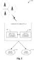
- Fig. 3illustrates a methodology 300 of evaluating accuracy of GPS data based on whether a mobile unit is in motion or not via evaluating signal strengths.
- Such signal strengthscan be received from adjacent towers, to verify whether a mobile unit is not moving and in a static position.
- Such verificationcan evaluate accuracy of the GPS reporting and hence can discard GPS data indication.
- mitigating GPS errorsbecomes important in applications that employ GPS data for verifying distances travelled by the mobile unit, and hence once static the GPS indicates erratic motion within vicinity of the point where the mobile device has in fact stopped - and hence errors are introduced. While the exemplary method is illustrated and described herein as a series of blocks representative of various events and/or acts, the subject innovation is not limited by the illustrated ordering of such blocks.
- GPS data for a mobile unitcan be acquired by the mobile unit and employed as input to applications being run thereby (e.g ., applications measuring total distance travelled.)
- a signal emitting from a tower adjacent to the mobile unitcan be detected.
- strength of such signalcan be compared to a signal received from the same tower by the mobile unit at a subsequent time.
- Fig. 4illustrates a block diagram for a system 400 that employs location and signal strength awareness.
- the system 400employs GPS, such that a user 402 operating a device 404 can be located according to lat/long data derived therefrom.
- a GPS satellite system 406continually communicates GPS signals 408 to the device 404 so that the device 404 can compute the lat/long data for the user.
- the device 404is a WAGPS device
- the device 404can register with a cellular network 410 having disposed therewith a wireless registration services system 412 that registers and uniquely identifies the user subscribed to that device 404.
- the coordinatescan be employed as search terms for search engines to identify adjacent towers of the communication network 416.
- returned search linkscan be accessed according to some predetermined criteria and/or rules.
- the signal strength from the same tower indicated by bars A & Bcan represent an inference that user 402 carrying the mobile unit 404 is in motion and hence GPS 408 can be trusted. If the signal strength A & B being received from the same tower are identical or within a predetermined threshold, the subject innovation can subsequently infer that the user carrying the mobile unit 404 is in a static position and hence the GPS data should not be trusted.
- Other websitescan also be automatically accessed to obtain additional information regarding parameters that can affect signal strength; such as weather information from a weather website 420, including temperature, humidity and barometric pressure data, if provided for the location of the user. It is to be appreciated that many different types of rules (or policies) can be implemented to cause automatic searching and linking of website data sources for parameters affecting the signal strength.
- the direction and speed of the user 402can also be corroborated via motion analyzers that are associated with the mobile unit 404. If the user 402 should enter a GPS shadow, or it is determined from user course and speed that the user is about to enter the shadow, other data and operations can be processed.
- a shadow mapping and log website 426provides a database of shadow mappings that are associated with location of the user 402.
- Fig. 5illustrates a related methodology 500 of mitigating errors in accordance with an aspect of the subject innovation.
- a difference in signal strength during two instancesare verified to be within a predetermined threshold. If so, the methodology proceeds to act 515 wherein GPS data can be discarded since a static behavior or position can be detected for the mobile unit -(the GPS can indicate erratic motion within vicinity of the point where the mobile device has stopped or in static position, and hence errors are introduced.) Otherwise, the methodology 500 proceeds to act 520 wherein motion of the mobile unit can be inferred. Such inference can then be corroborated with other type of motion analysis associated with the mobile device, at 530.
- motion detector devicese.g ., accelerometers, speedometers, and the like
- GPS datacan be employed as input for applications verifying distances travelled.
- Fig. 6illustrates an exemplary system that employs signal strength from multiple access wireless communication system 600 to mitigate errors in GPS data for the mobile units 616 and 622.
- the wireless communication system 600can include one or more towers or base stations in contact with one or more user devices. Each base station provides coverage for a plurality of sectors.
- a three-sector base station 602is illustrated that includes multiple antenna groups, one including antennas 604 and 606, another including antennas 608 and 610, and a third including antennas 612 and 614. According to the figure, only two antennas are shown for each antenna group, however, more or fewer antennas may be utilized for each antenna group.
- Mobile device 616is in communication with antennas 612 and 614, where antennas 612 and 614 transmit signals to mobile device 616 over forward link 618 and receive information from mobile device 616 over reverse link 620.
- Forward link(or downlink) refers to the communication link from the base stations to mobile devices
- the reverse link(or uplink) refers to the communication link from mobile devices to the base stations.
- Mobile device 622is in communication with antennas 604 and 606, where antennas 604 and 606 transmit information to mobile device 622 over forward link 624 and receive information from mobile device 622 over reverse link 626.
- communication linksmight utilize different frequencies for communication.
- forward link 618might use a different frequency than the frequency utilized by reverse link 620.
- Each group of antennas and/or the area in which they are designated to communicatecan be referred to as a sector of base station 602.
- antenna groupseach are designed to communicate to mobile devices in a sector or the areas covered by base station 602.
- a base stationmay be a fixed station used for communicating with the terminals.
- the transmitting antennas of base station 602can utilize beamforming in order to improve a signal-to-noise ratio of forward links for the different mobile devices 616 and 622.
- a constant signal strength received by the mobile unit 616 or 622 during a predetermined periodcan be inferred to indicate static ( e.g ., non-moving) mobile unit.
- a change in signal strength during a predetermined time framecan be inferred to indicate that the mobile unit has in fact moved.
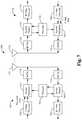
- Fig. 7illustrates an exemplary wireless communication system 700 that mitigates errors in positioning systems by employing signal strengths of towers(s) to verify motion for the mobile unit.
- Wireless communication system 700depicts one base station and one terminal for sake of brevity.
- system 700can include more than one base station or access point and/or more than one terminal or user device, wherein additional base stations and/or terminals can be substantially similar or different from the exemplary base station and terminal described below.
- the base station and/or the terminalcan employ the systems and/or methods described herein to facilitate wireless communication there between.
- a transmit (TX) data processor 710receives, formats, codes, interleaves, and modulates (or symbol maps) traffic data and provides modulation symbols ("data symbols").
- a symbol modulator 715receives and processes the data symbols and pilot symbols and provides a stream of symbols.
- a symbol modulator 715multiplexes data and pilot symbols and obtains a set of N transmit symbols.
- Each transmit symbolcan be a data symbol, a pilot symbol, or a signal value of zero.
- the pilot symbolscan be sent continuously in each symbol period.
- the pilot symbolscan be frequency division multiplexed (FDM), orthogonal frequency division multiplexed (OFDM), time division multiplexed (TDM), frequency division multiplexed (FDM), or code division multiplexed (CDM).
- a transmitter unit (TMTR) 720receives and converts the stream of symbols into one or more analog signals and further conditions (e.g ., amplifies, filters, and frequency upconverts) the analog signals to generate a downlink signal suitable for transmission over the wireless channel.
- the downlink signalis then transmitted through an antenna 725 to the terminals.
- an antenna 735receives the downlink signal and provides a received signal to a receiver unit (RCVR) 740.
- Receiver unit 740conditions (e.g., filters, amplifies, and frequency downconverts) the received signal and digitizes the conditioned signal to obtain samples.
- a symbol demodulator 745obtains N (an integer) received symbols and provides received pilot symbols to a processor 750 for channel estimation.
- Symbol demodulator 745further receives a frequency response estimate for the downlink from processor 750, performs data demodulation on the received data symbols to obtain data symbol estimates (which are estimates of the transmitted data symbols), and provides the data symbol estimates to an RX data processor 755, which demodulates (i.e ., symbol demaps), deinterleaves, and decodes the data symbol estimates to recover the transmitted traffic data.
- RX data processor 755demodulates (i.e ., symbol demaps), deinterleaves, and decodes the data symbol estimates to recover the transmitted traffic data.
- the processing by symbol demodulator 745 and RX data processor 755is complementary to the processing by symbol modulator 715 and TX data processor 710, respectively, at access point 705.
- a TX data processor 760processes traffic data and provides data symbols.
- a symbol modulator 765receives and multiplexes the data symbols with pilot symbols, performs modulation, and provides a stream of symbols.
- a transmitter unit 770then receives and processes the stream of symbols to generate an uplink signal, which is transmitted by the antenna 735 to the access point 705.
- the uplink signal from terminal 730is received by the antenna 725 and processed by a receiver unit 775 to obtain samples.
- a symbol demodulator 780then processes the samples and provides received pilot symbols and data symbol estimates for the uplink.
- An RX data processor 785processes the data symbol estimates to recover the traffic data transmitted by terminal 730.
- a processor 790performs channel estimation for each active terminal transmitting on the uplink.
- Processors 790 and 750direct (e.g ., control, coordinate, manage, ...) operation at access point 705 and terminal 730, respectively. Respective processors 790 and 750 can be associated with memory units (not shown) that store program codes and data. Processors 790 and 750 can also perform computations to derive frequency and impulse response estimates for the uplink and downlink, respectively.
- multiple terminalscan transmit concurrently on the uplink.
- the pilot subbandscan be shared among different terminals.
- the channel estimation techniquescan be employed in cases where the pilot subbands for each terminal span the entire operating band (possibly except for the band edges). Such a pilot subband structure would be desirable to obtain frequency diversity for each terminal.
- the techniques described hereincan be implemented by various means. For example, such techniques can be implemented in hardware, software, or a combination thereof.
- the processing units used for channel estimationmay be implemented within one or more application specific integrated circuits (ASICs), digital signal processors (DSPs), digital signal processing devices (DSPDs), programmable logic devices (PLDs), field programmable gate arrays (FPGAs), processors, controllers, microcontrollers, microprocessors, other electronic units designed to perform the functions described herein, or a combination thereof.
- ASICsapplication specific integrated circuits
- DSPsdigital signal processors
- DSPDsdigital signal processing devices
- PLDsprogrammable logic devices
- FPGAsfield programmable gate arrays
- processorscontrollers, microcontrollers, microprocessors, other electronic units designed to perform the functions described herein, or a combination thereof.
- implementationcan be through modules (e.g ., procedures, functions, and so on) that perform the functions described herein.
- the software codesmay be stored in memory unit and executed by the processors 790 and 750.
- An exemplary codecan include:
- the signal strengthcan be a received signal level or field strength; or be in form of a relative/unit less index that corresponds to magnitude of an electric field at a reference point (e.g ., number of "bars" on a cell phone screen.)
- a constant signal strength during a predetermined periodcan be inferred to indicate static (e.g ., non-moving) mobile unit.
- a change in signal strength during a predetermined time framecan be inferred to indicate that the mobile unit has moved.
- Such detection component and the comparator componentcan be part of the mobile unit, or can be positioned as part of a central control system that further employs triangulation procedures to infer whether the mobile unit is static or in motion. Such becomes important in applications that employ GPS data for verifying distances travelled as the GPS indicates erratic motion within vicinity of the point where the mobile device has stopped, and hence are introduced.
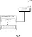
- Fig. 8illustrates an artificial intelligence component 810 for correction of GPS according to an aspect of the subject innovation.
- the term "inference”refers generally to the process of reasoning about or inferring states of the system, environment, and/or user from a set of observations as captured via events and/or data. Inference can be employed to identify a specific context or action, or can generate a probability distribution over states, for example. The inference can be probabilistic-that is, the computation of a probability distribution over states of interest based on a consideration of data and events. Inference can also refer to techniques employed for composing higher-level events from a set of events and/or data. Such inference results in the construction of new events or actions from a set of observed events and/or stored event data, whether or not the events are correlated in close temporal proximity, and whether the events and data come from one or several event and data sources.
- the inference component 810can employ any of a variety of suitable AI-based schemes as described supra in connection with facilitating various aspects of the herein described invention.
- a process for learning explicitly or implicitly when to discard GPS datacan be facilitated via an automatic classification system and process.
- Classificationcan employ a probabilistic and/or statistical-based analysis (e.g ., factoring into the analysis utilities and costs) to prognose or infer an action that a user desires to be automatically performed.
- a support vector machine (SVM) classifiercan be employed.
- Other classification approachesinclude Bayesian networks, decision trees, and probabilistic classification models providing different patterns of independence can be employed.
- Classification as used hereinalso is inclusive of statistical regression that is utilized to develop models of priority.
- the subject innovationcan employ classifiers that are explicitly trained (e.g ., via a generic training data) as well as implicitly trained (e.g., via observing user behavior, receiving extrinsic information) so that the classifier is used to automatically determine according to a predetermined criteria which answer to return to a question.
- SVM'sthat are well understood, SVM's are configured via a learning or training phase within a classifier constructor and feature selection module.
- a componentcan be, but is not limited to being, a process running on a processor, a processor, an object, an instance, an executable, a thread of execution, a program and/or a computer.
- an application running on a computer and the computercan be a component.
- One or more componentsmay reside within a process and/or thread of execution and a component may be localized on one computer and/or distributed between two or more computers.
- exemplaryis used herein to mean serving as an example, instance or illustration. Any aspect or design described herein as “exemplary” is not necessarily to be construed as preferred or advantageous over other aspects or designs. Similarly, examples are provided herein solely for purposes of clarity and understanding and are not meant to limit the subject innovation or portion thereof in any manner. It is to be appreciated that a myriad of additional or alternate examples could have been presented, but have been omitted for purposes of brevity.
- computer readable mediacan include but are not limited to magnetic storage devices (e.g., hard disk, floppy disk, magnetic strips%), optical disks (e.g ., compact disk (CD), digital versatile disk (DVD)%), smart cards, and flash memory devices (e.g ., card, stick, key drive).
- a carrier wavecan be employed to carry computer-readable electronic data such as those used in transmitting and receiving electronic mail or in accessing a network such as the Internet or a local area network (LAN).
- LANlocal area network
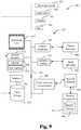
- Figs. 9 and 10are intended to provide a brief, general description of a suitable environment in which the various aspects of the disclosed subject matter may be implemented. While the subject matter has been described above in the general context of computer-executable instructions of a computer program that runs on a computer and/or computers, those skilled in the art will recognize that the innovation also may be implemented in combination with other program modules. Generally, program modules include routines, programs, components, data structures, and the like, which perform particular tasks and/or implement particular abstract data types.
- the computer 912includes a processing unit 914, a system memory 916, and a system bus 918.
- the system bus 918couples system components including, but not limited to, the system memory 916 to the processing unit 914.
- the processing unit 914can be any of various available processors. Dual microprocessors and other multiprocessor architectures also can be employed as the processing unit 914.
- the system bus 918can be any of several types of bus structure(s) including the memory bus or memory controller, a peripheral bus or external bus, and/or a local bus using any variety of available bus architectures including, but not limited to, 11-bit bus, Industrial Standard Architecture (ISA), Micro-Channel Architecture (MSA), Extended ISA (EISA), Intelligent Drive Electronics (IDE), VESA Local Bus (VLB), Peripheral Component Interconnect (PCI), Universal Serial Bus (USB), Advanced Graphics Port (AGP), Personal Computer Memory Card International Association bus (PCMCIA), and Small Computer Systems Interface (SCSI).
- ISAIndustrial Standard Architecture
- MSAMicro-Channel Architecture
- EISAExtended ISA
- IDEIntelligent Drive Electronics
- VLBVESA Local Bus
- PCIPeripheral Component Interconnect
- USBUniversal Serial Bus
- AGPAdvanced Graphics Port
- PCMCIAPersonal Computer Memory Card International Association bus
- SCSISmall Computer Systems Interface
- the system memory 916includes volatile memory 920 and nonvolatile memory 922.
- the basic input/output system (BIOS)containing the basic routines to transfer information between elements within the computer 912, such as during start-up, is stored in nonvolatile memory 922.
- nonvolatile memory 922can include read only memory (ROM), programmable ROM (PROM), electrically programmable ROM (EPROM), electrically erasable ROM (EEPROM), or flash memory.
- Volatile memory 920includes random access memory (RAM), which acts as external cache memory.
- RAMis available in many forms such as synchronous RAM (SRAM), dynamic RAM (DRAM), synchronous DRAM (SDRAM), double data rate SDRAM (DDR SDRAM), enhanced SDRAM (ESDRAM), Synchlink DRAM (SLDRAM), and direct Rambus RAM (DRRAM).
- SRAMsynchronous RAM
- DRAMdynamic RAM
- SDRAMsynchronous DRAM
- DDR SDRAMdouble data rate SDRAM
- ESDRAMenhanced SDRAM
- SLDRAMSynchlink DRAM
- DRRAMdirect Rambus RAM
- Computer 912also includes removable/non-removable, volatile/non-volatile computer storage media.
- Fig. 9illustrates a disk storage 924, wherein such disk storage 924 includes, but is not limited to, devices like a magnetic disk drive, floppy disk drive, tape drive, Jaz drive, Zip drive, LS-60 drive, flash memory card, or memory stick.
- disk storage 924can include storage media separately or in combination with other storage media including, but not limited to, an optical disk drive such as a compact disk ROM device (CD-ROM), CD recordable drive (CD-R Drive), CD rewritable drive (CD-RW Drive) or a digital versatile disk ROM drive (DVD-ROM).
- CD-ROMcompact disk ROM device
- CD-R DriveCD recordable drive
- CD-RW DriveCD rewritable drive
- DVD-ROMdigital versatile disk ROM drive
- a removable or non-removable interfaceis typically used such as interface 926.
- Fig. 9describes software that acts as an intermediary between users and the basic computer resources described in suitable operating environment 910.
- Such softwareincludes an operating system 928.
- Operating system 928which can be stored on disk storage 924, acts to control and allocate resources of the computer system 912.
- System applications 930take advantage of the management of resources by operating system 928 through program modules 932 and program data 934 stored either in system memory 916 or on disk storage 924. It is to be appreciated that various components described herein can be implemented with various operating systems or combinations of operating systems.
- Input devices 936include, but are not limited to, a pointing device such as a mouse, trackball, stylus, touch pad, keyboard, microphone, joystick, game pad, satellite dish, scanner, TV tuner card, digital camera, digital video camera, web camera, and the like. These and other input devices connect to the processing unit 914 through the system bus 918 via interface port(s) 938.
- Interface port(s) 938include, for example, a serial port, a parallel port, a game port, and a universal serial bus (USB).
- Output device(s) 940use some of the same type of ports as input device(s) 936.
- a USB portmay be used to provide input to computer 912, and to output information from computer 912 to an output device 940.
- Output adapter 942is provided to illustrate that there are some output devices 940 like monitors, speakers, and printers, among other output devices 940 that require special adapters.
- the output adapters 942include, by way of illustration and not limitation, video and sound cards that provide a means of connection between the output device 940 and the system bus 918. It should be noted that other devices and/or systems of devices provide both input and output capabilities such as remote computer(s) 944.
- Computer 912can operate in a networked environment using logical connections to one or more remote computers, such as remote computer(s) 944.
- the remote computer(s) 944can be a personal computer, a server, a router, a network PC, a workstation, a microprocessor based appliance, a peer device or other common network node and the like, and typically includes many or all of the elements described relative to computer 912. For purposes of brevity, only a memory storage device 946 is illustrated with remote computer(s) 944.
- Remote computer(s) 944is logically connected to computer 912 through a network interface 948 and then physically connected via communication connection 950.
- Network interface 948encompasses communication networks such as local-area networks (LAN) and wide-area networks (WAN).
- LAN technologiesinclude Fiber Distributed Data Interface (FDDI), Copper Distributed Data Interface (CDDI), Ethernet/IEEE 802.3, Token Ring/IEEE 802.5 and the like.
- WAN technologiesinclude, but are not limited to, point-to-point links, circuit switching networks like Integrated Services Digital Networks (ISDN) and variations thereon, packet switching networks, and Digital Subscriber Lines (DSL).
- ISDNIntegrated Services Digital Networks
- DSLDigital Subscriber Lines
- Communication connection(s) 950refers to the hardware/software employed to connect the network interface 948 to the bus 918. While communication connection 950 is shown for illustrative clarity inside computer 912, it can also be external to computer 912.
- the hardware/software necessary for connection to the network interface 948includes, for exemplary purposes only, internal and external technologies such as, modems including regular telephone grade modems, cable modems and DSL modems, ISDN adapters, and Ethernet cards.
- Fig. 10is a schematic block diagram of a sample-computing environment 1000 that can be employed as part of mitigating GPS errors in accordance with an aspect of the subject innovation.
- the system 1000includes one or more client(s) 1010.
- the client(s) 1010can be hardware and/or software (e.g ., threads, processes, computing devices).
- the system 1000also includes one or more server(s) 1030.
- the server(s) 1030can also be hardware and/or software (e.g ., threads, processes, computing devices).
- the servers 1030can house threads to perform transformations by employing the components described herein, for example.
- One possible communication between a client 1010 and a server 1030may be in the form of a data packet adapted to be transmitted between two or more computer processes.
- the system 1000includes a communication framework 1050 that can be employed to facilitate communications between the client(s) 1010 and the server(s) 1030.
- the client(s) 1010are operatively connected to one or more client data store(s) 1060 that can be employed to store information local to the client(s) 1010.
- the server(s) 1030are operatively connected to one or more server data store(s) 1040 that can be employed to store information local to the servers 1030.
Landscapes
- Engineering & Computer Science (AREA)
- Radar, Positioning & Navigation (AREA)
- Remote Sensing (AREA)
- Computer Networks & Wireless Communication (AREA)
- Physics & Mathematics (AREA)
- General Physics & Mathematics (AREA)
- Position Fixing By Use Of Radio Waves (AREA)
- Mobile Radio Communication Systems (AREA)
- Navigation (AREA)
- Telephone Function (AREA)
Description
- Advances in computer technology (e.g., microprocessor speed, memory capacity, data transfer bandwidth, software functionality, and the like) have generally contributed to increased computer application in various industries. For example, today, cellular telephones running on state-of-the-art operating systems have increased computing power in hardware and increased features in software in relation to earlier technologies.
- For instance, cellular telephones are often equipped with built-in digital image capture devices (e.g., cameras) and microphones together with computing functionalities of personal digital assistants (PDAs). Since these devices combine the functionality of cellular telephones with the functionality of PDAs, they are commonly referred to as "smartphones." The hardware and software features available in these smartphones and similar technologically capable devices provide developers the capability and flexibility to build applications through a versatile platform. The increasing market penetration of these portable devices (e.g., PDAs) inspires programmers to build applications, Internet browsers,etc. for these smartphones.
- Moreover, the Internet continues to make available ever-increasing amounts of information, which can be stored in databases and accessed therefrom. Additionally, with the proliferation of portable terminals (e.g., notebook computers, cellular telephones, PDAs, smartphones and other similar communications devices), users are becoming more mobile, and hence, trackable with respect to buying habits and locations that they tend to frequent. For example, many devices are being designed with a geographic location tracking technology such as GPS for reasons of safety, finding travel destinations, and the like. Thus, it now becomes possible to determine the location of the user.
- Location identification systems are used in many aspects of everyday life. By way of example, it has become increasingly more common for GPS to be integrated into automobiles to assist in navigation. Generally, a GPS system can, by triangulation of signals from three satellites, pinpoint a current location virtually anywhere on earth to within a few meters.
- Knowledge of where the user has traveled can be of value to the user and to companies that seek to benefit economically by knowledge of the user location by providing location-based data and services to the user. As such, location-based services use knowledge of a user location to index into services and data that are likely to be useful at that location. For example, many modem handheld devices are equipped with multiple sensors (e.g., microphone, wireless transmitter, global positioning system -GPS- engine, camera, stylus, and the like), which are notified regarding local activities/services. Such can include reminder applications, which can supply user's relevant information at a given location, such as "You're near a grocery store, and you need milk at home." Other conventional applications such as geo-based reminders; and "electronic graffiti" systems can support a user who chooses to leave electronic notes (for oneself or others) that are associated with a particular location, such as "There is a better Thai restaurant one block north of here." Additionally, location-based tour guide applications offer relevant information about an exhibit or site at which the user is standing. These and most other location-based services share a need for a custom database dedicated to storing and serving data for specified locations.
- GPS relies on satellite visibility to determine a user's position on the ground. Typically, for scenarios where a user is static or standing still, the portable GPS tracker devices and readers are required to indicate that they are at such static position - otherwise, substantial errors can be induced in various positioning applications such as distance and path finding calculations. Conventional corrections for such errors are typically based on multi-lateration or triangulation techniques between source positions, which determine if the movement is due to movement of the mobile unit, or rather such perceived movement indicates GPS errors. Such calculations can also become very intensive and hence employ system resources that could have been used more efficiently for other tasks.
US 2006/119508 A1 describes an apparatus and method for conserving power on a mobile device through motion awareness. The method includes a motion model that receives location information from one or more receivers and an accelerometer. The motion model determines whether the mobile device is in motion based on the received information. If the mobile device is in motion, a scanning rate for the one or more receivers is determined based on a velocity vector, the velocity vector being determined from the received information. The determined scanning rate is sent to the one or more receivers to enable them to operate at the determined scanning rate. If the mobile device is not in motion, the scanning operations for the one or more receivers are halted while the mobile device is stationary and scanning operations for the one or more receivers are resumed when an indication that the mobile device is moving again is received from the accelerometer.WO 03/032003 A2 US 4,912,645 describes an automotive navigation system has a receiver for receiving data signals on present position of the vehicle transmitted from satellites. A present position detecting system detects the present position of the vehicle on the basis of the data signals. A display device shows the present position of the vehicle on the basis of the output of the present position detecting system. Change of the output of the present position detecting system to be given to the display device is inhibited when the vehicle is at a stop.- It is the object of the present invention to provide an improved computer-implemented system, and computer-implemented method for allowing to verify accuracy of GPS data of a mobile unit.
- This object is solved by the subject matter of the independent claims.
- Preferred embodiments are defined by the dependent claims.
- The following presents a simplified summary in order to provide a basic understanding of some aspects described herein. This summary is not an extensive overview of the claimed subject matter. It is intended to neither identify key or critical elements of the claimed subject matter nor delineate the scope thereof. Its sole purpose is to present some concepts in a simplified form as a prelude to the more detailed description that is presented later.
- The subject innovation mitigates errors in positioning systems, by employing signal strength(s) of signal sources (e.g., towers adjacent to a mobile unit; other mobile units, and the like) to verify whether such unit is in static position (e.g., not moving) and evaluate accuracy of the GPS reporting (e.g., discarding GPS data indication.) A detection component can detect strength of an incoming signal from a signal source to the mobile unit and a comparator component can compare strength of such signal to a strength thereof at a predetermined time, to infer whether such mobile unit is static or in motion.
- As such, a constant signal strength during a predetermined period can be inferred to indicate static (e.g., non-moving) mobile unit. Likewise, a change in signal strength during a predetermined period can be inferred to indicate that the mobile unit has moved. Such detection component and the comparator component can be part of the mobile unit, or can be positioned as part of a central control system that further employs triangulation procedures to infer whether the mobile unit is static or in motion. Such becomes important in applications that employ GPS data for verifying distances travelled as the GPS indicates erratic motion within vicinity of the point where the mobile device has stopped, and hence are introduced. Other motion detector devices (e.g., accelerometers, speedometers, altimeters and the like) can be further be employed to detect motion and hence validate reliance on GPS data.
- In a related methodology, initially a signal emitting from a tower adjacent to the mobile unit can be detected. Subsequently, strength of such signal can be compared to a signal received from the same tower by the mobile unit. If differences (e.g., an absolute difference) between such signal strengths are outside a predetermined range, then it can be inferred that the mobile unit is in fact in motion, and hence GPS data can be trusted. Otherwise, the GPS data can be discarded, since a static position is inferred. Put differently, the GPS data can be inferred to be erratic, and hence not reliable if difference of signal strengths are within the predetermined threshold for a given time period.
- To the accomplishment of the foregoing and related ends, certain illustrative aspects of the claimed subject matter are described herein in connection with the following description and the annexed drawings. These aspects are indicative of various ways in which the subject matter may be practiced, all of which are intended to be within the scope of the claimed subject matter. Other advantages and novel features may become apparent from the following detailed description when considered in conjunction with the drawings.
Fig. 1 illustrates a system that mitigates GPS errors according to an aspect of the subject innovation.Fig. 2 illustrates an error mitigation system according to a further aspect of the subject innovation.Fig. 3 illustrates a methodology of evaluating accuracy for GPS data based on whether a mobile unit is in motion or notvia evaluating signal strengths.Fig. 4 illustrates a block diagram for a system that employs location and signal strength awareness according to a further aspect of the subject innovation.Fig. 5 illustrates a related methodology of reducing GPS errors according to a further aspect of the subject innovation.Fig. 6 illustrates a communication system that employs signal strength from multiple access wireless communication systems according to a further aspect.Fig. 7 illustrates a wireless communication system that employs signal strength for mitigation of errors.Fig. 8 illustrates an inference component that can facilitate inferring a static position of a mobile unit with GPS capabilities according to an aspect of the subject innovation.Fig. 9 is a schematic block diagram of a sample-computing environment that can be employed as part of mitigation GPS errors in accordance with an aspect of the subject innovation.Fig. 10 illustrates an exemplary environment for implementing various aspects of the subject innovation.- The various aspects of the subject innovation are now described with reference to the annexed drawings, wherein like numerals refer to like or corresponding elements throughout. It should be understood, however, that the drawings and detailed description relating thereto are not intended to limit the claimed subject matter to the particular form disclosed. Rather, the intention is to cover all modifications, equivalents and alternatives falling within the spirit and scope of the claimed subject matter.
Fig. 1 illustrates a block diagram of anerror mitigation system 100 that mitigates GPS errors in positioning system according to an aspect of the subject innovation. Thesystem 100 employs signal strengths of communication tower(s) 115 (e.g., an adjacent tower) to verify whether amobile unit 125 is in not moving (e.g., in a static position). Such verification can evaluate accuracy of the GPS reporting and hence can discard GPS data indication. It is to be appreciated that the subject innovation is not limited to evaluating signal strengths received from a communication tower, and can be implemented in conjunction with any signal source such as signals received from other mobile units, and the like.- The
tower 115 can be communicatively coupled to other public or private networks, which enable transfer of information to and from mobile units with GPS capabilities. For example, the communication networks can typically include a plurality of base stations that provide wireless communication links to mobile communication devices. Such base stations may be stationary (e.g., fixed to the ground) or mobile and positioned to provide wide area coverage as the mobile communication device travels across different coverage areas. - Moreover, the
mobile unit 125 with GPS capabilities can employ directional or adaptive antennas. Directional and/or adaptive antennas are typically used to direct signal transmissions in a desired direction. For example, by using such antennas during transmission, the directional concentration of radiated energy beam towards a receiver significantly increases the amount of received power per unit of transmitted power. This generally improves the throughput rate of the transmitter-to-receiver link and allows higher rates of information transfer. - As the
mobile unit 125 moves around in the coverage area of the wireless network, it can come within range of other base stations that can provide a more optimal communication link than its existing link, which can be employed to verify static or dynamic motion. Therefore,communication device 125 can include a mechanism to periodically, continuously, or sporadically monitor if a better base station exists than its current base station. - Upon selection of a base station or
communication tower 115 that supplies a signal to themobile unit 125, theerror mitigation system 100 employs such signals to verify movement for themobile unit 125. As illustrated, theerror mitigation system 100 includes adetection component 110 and acomparator component 112. Thedetection component 110 can detect strength of an incoming signal to themobile unit 125 at different times such as signal strength S1 at time T1 and signal strength S2 at time T2. By comparing S1 and S2 the comparator can determine whether the signal strength has changed (e.g., beyond a predetermined threshold), and based thereon theerror mitigation system 100 infers whether movement has occurred for themobile unit 125. The signal strength can be a received signal level or field strength; or be in form of a relative/unit-less index that corresponds to magnitude of an electric field at a reference point (e.g., number of "bars" on a cell phone screen.) As such, a constant signal strength during a predetermined period can be inferred to indicate static (e.g., non-moving) mobile unit. Likewise, a change in signal strength during a predetermined period can be inferred to indicate that the mobile unit has moved. Such detection component and the comparator component can be part of the mobile unit, or can be positioned as part of a central control system that further employs triangulation procedures to infer whether the mobile unit is static or in motion. Such becomes important in applications that employ GPS data for verifying distances travelled as the GPS indicates erratic motion within vicinity of the point where the mobile device has stopped, and hence are introduced. Other motion detector devices (e.g., accelerometers, speedometers, and the like) can be further be employed to detect motion and hence validate reliance on GPS data. As will be described in detailinfra, besides using signal strength related metrics, the mobile unit can also employ motion sensors/analyzers to verify whether mobile unit is in motion. Fig. 2 illustrates anerror mitigation system 200 according to a further aspect of the subject innovation. Theerror mitigation system 200 can affect identification and/or generation of location-based data and services. Generally,system 200 can include alocation detection component 206 and amotion analyzer component 208. Thelocation detection component 206 facilitates identifying and providing content that corresponds to a location of a portable device. In accordance therewith, thelocation detention component 206 can facilitate identifying a location of a device and thereafter can identify data and/or services that correspond to the location. Likewise, themotion analyzer component 208 can include devices such as accelerometers, speedometers and the like, wherein a motion of the mobile unit is detected. Based on such detention for analyzing motion of the mobile unit the GPS date can be trusted and hence accepted at 216, or otherwise discarded at 214. For example, if no motion is detected either through themotion analyzer component 208 or as a result of the detection and comparator components ofFig. 1 , then the GPS data cannot typically be relied thereupon and GPS discarded. Alternatively, if motion is detected by the motion analyzer component and/orvia the signal strength analysis ofFig. 1 , then an inference can be made regarding motion of the mobile unit and hence GPS data can be accepted.- As explained earlier, the geographic location data is determined by the
location detection component 206via receiving geographic location signals of a GPS (global positioning system) technology. For example, GPS can consist of a constellation of twenty-four satellites each in its own orbit approximately 11,000 miles above the earth. Each of the satellites orbits the earth in about twelve hours, and the positions of which are monitored by ground stations. The satellites can include atomic clocks for extremely accurate timing (e.g., within three nanoseconds of each other) that provides the capability to locate the location component 102 (e.g., a handheld terrestrial receiver) on the earth within, in some applications, one meter resolution. - The GPS location data can be receivedvia the
location detection component 206 that is, for example, a wireless assisted GPS (WAGPS) device such as a GPS-enabled cellular telephone, GPS-enabled PDA, and the like. Such WAGPS facilitates the transmission of the GPS location data from thelocation detection component 206 to a remote location. Generally, this can occur through a cellular network where the location component is a cellular telephone, to an IP network (e.g., the Internet), and terminating at the remote location, node or device on the Internet or on a subnet thereof. - When receiving geographic location signals from several of the GPS satellites, the
location detection component 206 can calculate the distance to each satellite of the communicating satellites and then calculate its own position, on or above the surface of the earth. However, when the signals are interrupted or degraded due to terrestrial structures, such interrupt time and position information can be useful in determining GPS shadow. A shadow is an area of communications interruption or total signal blockage. In the context of GPS, shadows are areas where a terrestrial receiver cannot receive adequate GPS signals due to signal blockage or degradation by any of many types of structures that include buildings, bridges, trees, hills, water (when submerged) and tunnels, for example. Such shadow information can be utilized in accordance with the subject invention, and is describedinfra. - It is to be appreciated, that the geographic location technology and/or motion detection technology can also include, for example, WiFi triangulation, cellular telephone triangulation, radio frequency signal strengths, and digital television signals.
Fig. 3 illustrates amethodology 300 of evaluating accuracy of GPS data based on whether a mobile unit is in motion or notvia evaluating signal strengths. Such signal strengths can be received from adjacent towers, to verify whether a mobile unit is not moving and in a static position. Such verification can evaluate accuracy of the GPS reporting and hence can discard GPS data indication. For example, mitigating GPS errors becomes important in applications that employ GPS data for verifying distances travelled by the mobile unit, and hence once static the GPS indicates erratic motion within vicinity of the point where the mobile device has in fact stopped - and hence errors are introduced. While the exemplary method is illustrated and described herein as a series of blocks representative of various events and/or acts, the subject innovation is not limited by the illustrated ordering of such blocks. For instance, some acts or events may occur in different orders and/or concurrently with other acts or events, apart from the ordering illustrated herein, in accordance with the innovation. In addition, not all illustrated blocks, events or acts, may be required to implement a methodology in accordance with the subject innovation. Moreover, it will be appreciated that the exemplary method and other methods according to the innovation may be implemented in association with the method illustrated and described herein, as well as in association with other systems and apparatus not illustrated or described.- Initially and at 310 GPS data for a mobile unit can be acquired by the mobile unit and employed as input to applications being run thereby (e.g., applications measuring total distance travelled.) Next and at 320 a signal emitting from a tower adjacent to the mobile unit can be detected. Subsequently and at 330 strength of such signal can be compared to a signal received from the same tower by the mobile unit at a subsequent time. At 340, a determination is made whether signal strength is the same at time T1 as compared to time T2. If so, the
methodology 300 infers a static position for the mobile unit and rejects GPS data at 350. Otherwise, themethodology 300 proceeds to act 360 wherein a dynamic position is inferred and GPS data accepted. Fig. 4 illustrates a block diagram for asystem 400 that employs location and signal strength awareness. Thesystem 400 employs GPS, such that auser 402 operating adevice 404 can be located according to lat/long data derived therefrom. AGPS satellite system 406 continually communicates GPS signals 408 to thedevice 404 so that thedevice 404 can compute the lat/long data for the user. If thedevice 404 is a WAGPS device, thedevice 404 can register with acellular network 410 having disposed therewith a wirelessregistration services system 412 that registers and uniquely identifies the user subscribed to thatdevice 404. Once the device/user location is knownvia the GPS, the coordinates can be employed as search terms for search engines to identify adjacent towers of thecommunication network 416.- Thus, returned search links can be accessed according to some predetermined criteria and/or rules. At
region 424, the signal strength from the same tower indicated by bars A & B can represent an inference thatuser 402 carrying themobile unit 404 is in motion and henceGPS 408 can be trusted. If the signal strength A & B being received from the same tower are identical or within a predetermined threshold, the subject innovation can subsequently infer that the user carrying themobile unit 404 is in a static position and hence the GPS data should not be trusted. - Other websites can also be automatically accessed to obtain additional information regarding parameters that can affect signal strength; such as weather information from a
weather website 420, including temperature, humidity and barometric pressure data, if provided for the location of the user. It is to be appreciated that many different types of rules (or policies) can be implemented to cause automatic searching and linking of website data sources for parameters affecting the signal strength. In a related aspect, the direction and speed of theuser 402 can also be corroboratedvia motion analyzers that are associated with themobile unit 404. If theuser 402 should enter a GPS shadow, or it is determined from user course and speed that the user is about to enter the shadow, other data and operations can be processed. For example, a shadow mapping andlog website 426 provides a database of shadow mappings that are associated with location of theuser 402. Fig. 5 illustrates arelated methodology 500 of mitigating errors in accordance with an aspect of the subject innovation. Initially and at 510 a difference in signal strength during two instances are verified to be within a predetermined threshold. If so, the methodology proceeds to act 515 wherein GPS data can be discarded since a static behavior or position can be detected for the mobile unit -(the GPS can indicate erratic motion within vicinity of the point where the mobile device has stopped or in static position, and hence errors are introduced.) Otherwise, themethodology 500 proceeds to act 520 wherein motion of the mobile unit can be inferred. Such inference can then be corroborated with other type of motion analysis associated with the mobile device, at 530. For example, other motion detector devices (e.g., accelerometers, speedometers, and the like) can be further be employed to detect motion and hence validate reliance on GPS data. Subsequently and at 540, the GPS data can be employed as input for applications verifying distances travelled.Fig. 6 illustrates an exemplary system that employs signal strength from multiple accesswireless communication system 600 to mitigate errors in GPS data for themobile units wireless communication system 600 can include one or more towers or base stations in contact with one or more user devices. Each base station provides coverage for a plurality of sectors. A three-sector base station 602 is illustrated that includes multiple antenna groups, one includingantennas antennas antennas Mobile device 616 is in communication withantennas antennas mobile device 616 overforward link 618 and receive information frommobile device 616 overreverse link 620. Forward link (or downlink) refers to the communication link from the base stations to mobile devices, and the reverse link (or uplink) refers to the communication link from mobile devices to the base stations.Mobile device 622 is in communication withantennas antennas mobile device 622 overforward link 624 and receive information frommobile device 622 overreverse link 626. In a FDD system, for example, communication links might utilize different frequencies for communication. For example,forward link 618 might use a different frequency than the frequency utilized byreverse link 620.- Each group of antennas and/or the area in which they are designated to communicate can be referred to as a sector of
base station 602. In one or more aspects, antenna groups each are designed to communicate to mobile devices in a sector or the areas covered bybase station 602. A base station may be a fixed station used for communicating with the terminals. In communication overforward links base station 602 can utilize beamforming in order to improve a signal-to-noise ratio of forward links for the differentmobile devices mobile unit Fig. 7 illustrates an exemplarywireless communication system 700 that mitigates errors in positioning systems by employing signal strengths of towers(s) to verify motion for the mobile unit.Wireless communication system 700 depicts one base station and one terminal for sake of brevity. However, it is to be appreciated thatsystem 700 can include more than one base station or access point and/or more than one terminal or user device, wherein additional base stations and/or terminals can be substantially similar or different from the exemplary base station and terminal described below. In addition, it is to be appreciated that the base station and/or the terminal can employ the systems and/or methods described herein to facilitate wireless communication there between.- As illustrated in
Fig. 7 , on a downlink, ataccess point 705, a transmit (TX)data processor 710 receives, formats, codes, interleaves, and modulates (or symbol maps) traffic data and provides modulation symbols ("data symbols"). Asymbol modulator 715 receives and processes the data symbols and pilot symbols and provides a stream of symbols. Asymbol modulator 715 multiplexes data and pilot symbols and obtains a set of N transmit symbols. Each transmit symbol can be a data symbol, a pilot symbol, or a signal value of zero. The pilot symbols can be sent continuously in each symbol period. Moreover, the pilot symbols can be frequency division multiplexed (FDM), orthogonal frequency division multiplexed (OFDM), time division multiplexed (TDM), frequency division multiplexed (FDM), or code division multiplexed (CDM). - A transmitter unit (TMTR) 720 receives and converts the stream of symbols into one or more analog signals and further conditions (e.g., amplifies, filters, and frequency upconverts) the analog signals to generate a downlink signal suitable for transmission over the wireless channel. The downlink signal is then transmitted through an
antenna 725 to the terminals. Atterminal 730, anantenna 735 receives the downlink signal and provides a received signal to a receiver unit (RCVR) 740.Receiver unit 740 conditions (e.g., filters, amplifies, and frequency downconverts) the received signal and digitizes the conditioned signal to obtain samples. Asymbol demodulator 745 obtains N (an integer) received symbols and provides received pilot symbols to aprocessor 750 for channel estimation.Symbol demodulator 745 further receives a frequency response estimate for the downlink fromprocessor 750, performs data demodulation on the received data symbols to obtain data symbol estimates (which are estimates of the transmitted data symbols), and provides the data symbol estimates to anRX data processor 755, which demodulates (i.e., symbol demaps), deinterleaves, and decodes the data symbol estimates to recover the transmitted traffic data. The processing bysymbol demodulator 745 andRX data processor 755 is complementary to the processing bysymbol modulator 715 andTX data processor 710, respectively, ataccess point 705. - On the uplink, a
TX data processor 760 processes traffic data and provides data symbols. Asymbol modulator 765 receives and multiplexes the data symbols with pilot symbols, performs modulation, and provides a stream of symbols. Atransmitter unit 770 then receives and processes the stream of symbols to generate an uplink signal, which is transmitted by theantenna 735 to theaccess point 705. - At
access point 705, the uplink signal fromterminal 730 is received by theantenna 725 and processed by areceiver unit 775 to obtain samples. Asymbol demodulator 780 then processes the samples and provides received pilot symbols and data symbol estimates for the uplink. AnRX data processor 785 processes the data symbol estimates to recover the traffic data transmitted byterminal 730. Aprocessor 790 performs channel estimation for each active terminal transmitting on the uplink. Processors access point 705 and terminal 730, respectively.Respective processors Processors - For a multiple-access system (e.g., FDMA, OFDMA, CDMA, TDMA, and the like), multiple terminals can transmit concurrently on the uplink. For such a system, the pilot subbands can be shared among different terminals. The channel estimation techniques can be employed in cases where the pilot subbands for each terminal span the entire operating band (possibly except for the band edges). Such a pilot subband structure would be desirable to obtain frequency diversity for each terminal. It is to be appreciated that the techniques described herein can be implemented by various means. For example, such techniques can be implemented in hardware, software, or a combination thereof. For a hardware implementation, the processing units used for channel estimation may be implemented within one or more application specific integrated circuits (ASICs), digital signal processors (DSPs), digital signal processing devices (DSPDs), programmable logic devices (PLDs), field programmable gate arrays (FPGAs), processors, controllers, microcontrollers, microprocessors, other electronic units designed to perform the functions described herein, or a combination thereof. With software, implementation can be through modules (e.g., procedures, functions, and so on) that perform the functions described herein. The software codes may be stored in memory unit and executed by the
processors - An exemplary code can include:
//Do this for each stationary signal source in the vicinity OnGPSSensorUpdate() { //Check received signal strength indicators... if ((CurrentSourceSignalValue == previousSignalValue) && (previousMaxValue== GetCurrentSignalSourceMAX()) { //Do not trust the GPS read. There was either no movement according to the other signals and we have not swapped sources } else { //Either the source changed or there WAS movement according to the signal strength. Pos = Read GPSSensor(); // Either way, accept the current position!- Example 1: A computer implemented system comprising the following computer executable components:
- a mobile unit with GPS capabilities; and
- an error mitigation system for GPS data associated with the mobile unit, the error mitigation system evaluates signal strength from a signal source(s) to infer a motion of the mobile unit and accept or discard the GPS data based on the motion.
- Example 2: The computer implemented system of example 1, the error mitigation system further comprising a detection component that detects signals from the signal source(s).
- Example 3: The computer implemented system of example 2 further comprising a comparator component that determines differences in signal strength at different times.
- Example 4: The computer implemented system of example 2 further comprising a shadow mapping and log that records GPS shadows.
- Example 5: The computer implemented system of example 2 further comprising data stores that maintain parameters affecting signal strength.
- Example 6: The computer implemented system of example 2 further comprising an inference component that infers position of the mobile unit.
- Example 7: The computer implemented system of example 2 further comprising a location detection component.
- Example 8: The computer implemented system of example 2, rejection of the GPS data based on verification of a static position for the mobile unit.
- Example 9: The computer implemented system of example 2, acceptance of the GPS data based on verification of a dynamic position for the mobile unit.
- Example 10: A computer implemented method comprising the following computer executable acts:
- acquiring GPS data by a mobile unit;
- evaluating signal strength from a signal source transmitting to the mobile unit via an error mitigation system; and
- accepting or rejecting the GPS data based on the signal strength evaluated by the error mitigation system.
- Example 11: The computer implemented method of example 10 further comprising inferring motion for the mobile unit and accepting the GPS data.
- Example 12: The computer implemented method of example 10 further comprising inferring static position for the mobile unit and discarding the GPS data.
- Example 13: The computer implemented method of example 10 further comprising comparing signal strengths from same signal source at different times via a comparator component.
- Example 14: The computer implemented method of example 11 further comprising corroborating motion of the mobile unit with a motion analyzer associated with the mobile unit.
- Example 15: The computer implemented method of example 13 further comprising determining whether a difference in the signal strengths is within predetermined threshold.
- Example 16: The computer implemented method of example 13 further
comprising employing heuristics via an artificial intelligence component to infer motion of the mobile unit. - Example 17: The computer implemented method of example 13 further comprising retrieving parameters from a server that affect the signal strength.
- Example 18: The computer implemented method of example 13 further comprising determining motion of the mobile unit via one of a speedometer or accelerometer, or altimeter or a combination thereof.
- Example 19: The computer implemented method of example 13 further comprising implementing the signal strength as a bar indication.
- Example 20: A computer implemented system comprising the following computer executable components:
- means for inferring motion of a mobile unit based on signal strength from a signal source; and
- means for mitigating GPS errors associated with motion of the mobile unit based on the signal strengths.
Claims (9)
- A computer-implemented system comprising the following computer-executable components:a mobile unit (125; 404) with GPS capabilities for acquiring GPS data, wherein the acquired GPS data indicates a motion of the mobile unit; andan error mitigation system (200) for verifying the GPS data associated with the mobile unit, wherein the error mitigation system further comprises a detection component (110) that detects signals from one or more signal sources and a comparator component (112) that determines differences in signal strength at different times, the error mitigation system evaluates signal strength from the one or more signal sources to infer a motion of the mobile unit and if a difference in signal strength at different times has changed beyond a predetermined threshold, infer a dynamic position of the mobile unit and accept the GPS data, and if the difference in signal strength at different times has not changed beyond the predetermined threshold, infer a static position of the mobile unit and discard the GPS data indicating an erratic motion, wherein the one or more signal sources are a base station or a communication tower.
- The computer-implemented system of claim 1 further comprising a shadow mapping and log that records GPS shadows.
- The computer-implemented system of claim 1 further comprising data stores that maintain parameters affecting signal strength.
- The computer-implemented system of claim 1 further comprising an inference component (810) that infers position of the mobile unit.
- The computer-implemented system of claim 1 further comprising a location detection component (206).
- The computer-implemented system of claim 1, rejection of the GPS data based on verification of the static position for the mobile unit (125; 404).
- The computer-implemented system of claim 1, acceptance of the GPS data based on verification of the dynamic position for the mobile unit (125; 404).
- A computer-implemented method comprising the following computer-executable acts:acquiring GPS data by a mobile unit (125; 404), wherein the acquired GPS data indicates a motion of the mobile unit;evaluating signal strength from a signal source transmitting to the mobile unit via an error mitigation system (200), wherein the error mitigation system verifies said GPS data, and wherein the signal source is a base station or a communication tower;comparing signal strengths from same signal source at different times via a comparator component (112);accepting the GPS data and inferring a dynamic position of the mobile unit if a difference in signal strength at different times has changed beyond a predetermined threshold; andrejecting the GPS data indicating an erratic motion and inferring a static position of the mobile unit if the difference in signal strength at different times has not changed beyond a predetermined threshold.
- The computer-implemented method of claim 8 further comprising corroborating motion of the mobile unit with a motion analyzer (208) associated with the mobile unit (125; 404), or
further comprising employing heuristics via an artificial intelligence component (810) to infer motion of the mobile unit, or
further comprising retrieving parameters from a server (1030) that affect the signal strength, or
further comprising determining motion of the mobile unit via one of a speedometer or accelerometer, or altimeter or a combination thereof, or
further comprising implementing the signal strength as a bar indication.
Applications Claiming Priority (2)
| Application Number | Priority Date | Filing Date | Title |
|---|---|---|---|
| US12/344,820US8059027B2 (en) | 2008-12-29 | 2008-12-29 | Correcting GPS through secondary sensors and signal strength |
| PCT/US2009/067786WO2010077791A2 (en) | 2008-12-29 | 2009-12-11 | Correcting gps through secondary sensors and signal strength |
Publications (3)
| Publication Number | Publication Date |
|---|---|
| EP2382831A2 EP2382831A2 (en) | 2011-11-02 |
| EP2382831A4 EP2382831A4 (en) | 2012-09-19 |
| EP2382831B1true EP2382831B1 (en) | 2017-05-17 |
Family
ID=42284237
Family Applications (1)
| Application Number | Title | Priority Date | Filing Date |
|---|---|---|---|
| EP09836794.9AActiveEP2382831B1 (en) | 2008-12-29 | 2009-12-11 | Correcting gps through secondary sensors and signal strength |
Country Status (6)
| Country | Link |
|---|---|
| US (1) | US8059027B2 (en) |
| EP (1) | EP2382831B1 (en) |
| JP (1) | JP2012514385A (en) |
| CN (1) | CN102273289B (en) |
| ES (1) | ES2637154T3 (en) |
| WO (1) | WO2010077791A2 (en) |
Families Citing this family (29)
| Publication number | Priority date | Publication date | Assignee | Title |
|---|---|---|---|---|
| US7640105B2 (en) | 2007-03-13 | 2009-12-29 | Certus View Technologies, LLC | Marking system and method with location and/or time tracking |
| US9659268B2 (en)* | 2008-02-12 | 2017-05-23 | CertusVies Technologies, LLC | Ticket approval system for and method of performing quality control in field service applications |
| US8612271B2 (en) | 2008-10-02 | 2013-12-17 | Certusview Technologies, Llc | Methods and apparatus for analyzing locate and marking operations with respect to environmental landmarks |
| US9208458B2 (en) | 2008-10-02 | 2015-12-08 | Certusview Technologies, Llc | Methods and apparatus for analyzing locate and marking operations with respect to facilities maps |
| US20090327024A1 (en)* | 2008-06-27 | 2009-12-31 | Certusview Technologies, Llc | Methods and apparatus for quality assessment of a field service operation |
| US9473626B2 (en) | 2008-06-27 | 2016-10-18 | Certusview Technologies, Llc | Apparatus and methods for evaluating a quality of a locate operation for underground utility |
| US9208464B2 (en) | 2008-10-02 | 2015-12-08 | Certusview Technologies, Llc | Methods and apparatus for analyzing locate and marking operations with respect to historical information |
| CA2691780C (en)* | 2009-02-11 | 2015-09-22 | Certusview Technologies, Llc | Management system, and associated methods and apparatus, for providing automatic assesment of a locate operation |
| US7941379B1 (en)* | 2009-06-25 | 2011-05-10 | Symantec Corporation | Systems and methods for using geo-location information in sensitive internet transactions |
| US8489112B2 (en) | 2009-07-29 | 2013-07-16 | Shopkick, Inc. | Method and system for location-triggered rewards |
| US8341099B2 (en)* | 2010-03-12 | 2012-12-25 | Microsoft Corporation | Semantics update and adaptive interfaces in connection with information as a service |
| US10250678B2 (en)* | 2010-07-07 | 2019-04-02 | Qualcomm Incorporated | Hybrid modes for peer discovery |
| US20120036140A1 (en)* | 2010-08-05 | 2012-02-09 | Certusview Technologies, Llc | Methods and apparatus for analyzing locate and marking operations by comparing filtered locate and/or marking information |
| US8548739B2 (en)* | 2011-02-10 | 2013-10-01 | Telenav, Inc. | Navigation system with interactive accelerometer mechanism and method of operation thereof |
| EP2487506B1 (en)* | 2011-02-10 | 2014-05-14 | Toll Collect GmbH | Positioning device, method and computer program product for signalling that a positioning device is not functioning as intended |
| KR101105848B1 (en)* | 2011-04-14 | 2012-01-13 | 한국과학기술원 | A mobile terminal including a sensor, a wireless network system including the same, and a scanning method of a wireless network system |
| FR2978835B1 (en)* | 2011-08-05 | 2013-08-09 | Thales Sa | SATELLITE PAYLOAD FOR INCREASE SYSTEMS |
| JP2013183356A (en)* | 2012-03-02 | 2013-09-12 | Nec Access Technica Ltd | Mobile terminal device |
| EP2653945B1 (en)* | 2012-04-19 | 2016-06-15 | Schneider Electric Buildings LLC | Association of a portable sensor device in a building management system |
| CN103636142A (en)* | 2012-06-14 | 2014-03-12 | 华为终端有限公司 | Calibration method of air pressure for mobile device, calibration device and mobile device |
| US9002641B2 (en) | 2012-10-05 | 2015-04-07 | Hand Held Products, Inc. | Navigation system configured to integrate motion sensing device inputs |
| US9405011B2 (en) | 2012-10-05 | 2016-08-02 | Hand Held Products, Inc. | Navigation system configured to integrate motion sensing device inputs |
| US9301096B2 (en)* | 2014-05-08 | 2016-03-29 | Qualcomm Incorporated | Range rate based stopped detection |
| US9804271B2 (en)* | 2015-01-02 | 2017-10-31 | Samsung Electronics Co., Ltd | Adaptive GNSS power saving control |
| JP6145623B2 (en)* | 2015-03-23 | 2017-06-14 | 石川県 | POSITION MEASUREMENT SYSTEM, POSITION MEASUREMENT DEVICE, POSITION MEASUREMENT METHOD, AND PROGRAM |
| DE102015214834A1 (en)* | 2015-08-04 | 2017-02-09 | Robert Bosch Gmbh | Concept for locating an objective body located within a parking lot |
| CN106813669B (en)* | 2015-12-01 | 2020-01-03 | 骑记(厦门)科技有限公司 | Motion information correction method and device |
| WO2020100455A1 (en)* | 2018-11-12 | 2020-05-22 | 古野電気株式会社 | Gnss receiving device |
| CN111562605B (en) | 2020-04-24 | 2022-09-02 | 北京智行者科技有限公司 | Self-adaptive GPS error observed value identification method |
Family Cites Families (25)
| Publication number | Priority date | Publication date | Assignee | Title |
|---|---|---|---|---|
| US4912645A (en)* | 1987-03-26 | 1990-03-27 | Mazda Motor Corporation | Automotive navigation system |
| JP3161334B2 (en)* | 1996-07-29 | 2001-04-25 | 松下電器産業株式会社 | Position detection device |
| CA2220198A1 (en)* | 1996-11-05 | 1998-05-05 | Savannah River Srt, Inc. | Global positioning system recorder |
| JPH1073652A (en)* | 1997-07-23 | 1998-03-17 | Mazda Motor Corp | Navigation apparatus for vehicle |
| DE19842836A1 (en)* | 1998-09-18 | 2000-04-20 | Nokia Mobile Phones Ltd | Method for determining the position of a communication device and communication device for performing the method |
| ATE456809T1 (en)* | 1999-07-20 | 2010-02-15 | Qualcomm Inc | METHOD FOR DETERMINING RADIO SIGNAL CHANGE AND USING THIS INFORMATION TO IMPROVE RECEPTION AND PROCESSING OF SATELLITE POSITIONING SIGNALS |
| US20050026589A1 (en)* | 1999-07-29 | 2005-02-03 | Bryan Holland | Remote locator system using A E911-enabled wireless system |
| US6427077B1 (en)* | 2001-01-26 | 2002-07-30 | Motorola, Inc. | GPS enabled mobile stations and location methods therefor |
| US6754584B2 (en)* | 2001-02-28 | 2004-06-22 | Enpoint, Llc | Attitude measurement using a single GPS receiver with two closely-spaced antennas |
| US6853840B2 (en)* | 2001-03-02 | 2005-02-08 | Csi Wireless Llc | System and method for enabling and disabling devices based on RSSI analysis |
| US6861982B2 (en)* | 2001-08-16 | 2005-03-01 | Itt Manufacturing Enterprises, Inc. | System for determining position of an emitter |
| US6584331B2 (en)* | 2001-10-09 | 2003-06-24 | Nokia Corporation | Use of received signal strength indicator (RSSI) and global positioning system (GPS) to reduce power consumption in mobile station |
| KR100498987B1 (en)* | 2002-10-11 | 2005-07-01 | 엘지전자 주식회사 | Method for estimating location of vehicle in Global Positioning System Data's poor region |
| US7250907B2 (en)* | 2003-06-30 | 2007-07-31 | Microsoft Corporation | System and methods for determining the location dynamics of a portable computing device |
| US7409188B2 (en)* | 2003-11-26 | 2008-08-05 | Nokia Corporation | Method and apparatus for lowering power use by a ranging receiver |
| US7251493B2 (en)* | 2004-02-13 | 2007-07-31 | Sony Ericsson Mobile Communications Ab | Mobile terminals and methods for determining a location based on acceleration information |
| US20060038555A1 (en)* | 2004-08-20 | 2006-02-23 | Higgins Robert F | Self-training AC magnetic tracking systems to cover large areas |
| US7408506B2 (en)* | 2004-11-19 | 2008-08-05 | Intel Corporation | Method and apparatus for conserving power on a mobile device through motion awareness |
| US8032276B2 (en)* | 2004-12-07 | 2011-10-04 | Geotab, Inc. | Apparatus and method for optimally recording geographical position data |
| EP1710599B8 (en) | 2005-04-07 | 2016-03-23 | Intel Deutschland GmbH | Mobile device |
| US20060238347A1 (en)* | 2005-04-22 | 2006-10-26 | W.R. Parkinson, Co., Inc. | Object tracking system |
| US20070005363A1 (en)* | 2005-06-29 | 2007-01-04 | Microsoft Corporation | Location aware multi-modal multi-lingual device |
| US7925995B2 (en)* | 2005-06-30 | 2011-04-12 | Microsoft Corporation | Integration of location logs, GPS signals, and spatial resources for identifying user activities, goals, and context |
| US8014788B2 (en)* | 2006-05-08 | 2011-09-06 | Skyhook Wireless, Inc. | Estimation of speed of travel using the dynamic signal strength variation of multiple WLAN access points |
| US20080165737A1 (en)* | 2007-01-09 | 2008-07-10 | Uppala Subramanya R | Motion sensitive system selection for multi-mode devices |
- 2008
- 2008-12-29USUS12/344,820patent/US8059027B2/enactiveActive
- 2009
- 2009-12-11WOPCT/US2009/067786patent/WO2010077791A2/enactiveApplication Filing
- 2009-12-11CNCN200980153818.4Apatent/CN102273289B/enactiveActive
- 2009-12-11ESES09836794.9Tpatent/ES2637154T3/enactiveActive
- 2009-12-11JPJP2011543562Apatent/JP2012514385A/enactivePending
- 2009-12-11EPEP09836794.9Apatent/EP2382831B1/enactiveActive
Also Published As
| Publication number | Publication date |
|---|---|
| CN102273289A (en) | 2011-12-07 |
| JP2012514385A (en) | 2012-06-21 |
| US20100164787A1 (en) | 2010-07-01 |
| WO2010077791A2 (en) | 2010-07-08 |
| WO2010077791A3 (en) | 2010-08-26 |
| CN102273289B (en) | 2014-05-14 |
| EP2382831A4 (en) | 2012-09-19 |
| ES2637154T3 (en) | 2017-10-11 |
| EP2382831A2 (en) | 2011-11-02 |
| US8059027B2 (en) | 2011-11-15 |
Similar Documents
| Publication | Publication Date | Title |
|---|---|---|
| EP2382831B1 (en) | Correcting gps through secondary sensors and signal strength | |
| US20230305166A1 (en) | On demand positioning | |
| EP3327458B1 (en) | Method and apparatus for marking inconsistent position location data | |
| KR101554774B1 (en) | Method for determining a position of a mobile station using a wireless signal | |
| US7647171B2 (en) | Learning, storing, analyzing, and reasoning about the loss of location-identifying signals | |
| US20130017840A1 (en) | Position estimating for a mobile device | |
| CN108353248A (en) | Method and apparatus for locating a mobile device | |
| EP1903349A1 (en) | Mobile communication terminal for receiving position information service and method thereof | |
| Leu et al. | Improving indoor positioning precision by using received signal strength fingerprint and footprint based on weighted ambient Wi-Fi signals | |
| US20150141042A1 (en) | Mobile terminal, system and method | |
| US9411038B2 (en) | Dynamic compensation for wireless device location determination | |
| Sung et al. | Simplified KF-based energy-efficient vehicle positioning for smartphones | |
| CN115826025B (en) | Indoor and outdoor integrated positioning system and method | |
| US8886221B1 (en) | Mobile device location estimation using local location data | |
| Ramakrishnan et al. | Robust Wi-Fi assisted GNSS positioning in urban canyons | |
| JP7689330B2 (en) | Positioning terminal, information processing device, and positioning method | |
| Lim | Smart proximity based service agents on mobile handsets |
Legal Events
| Date | Code | Title | Description |
|---|---|---|---|
| PUAI | Public reference made under article 153(3) epc to a published international application that has entered the european phase | Free format text:ORIGINAL CODE: 0009012 | |
| 17P | Request for examination filed | Effective date:20110727 | |
| AK | Designated contracting states | Kind code of ref document:A2 Designated state(s):AT BE BG CH CY CZ DE DK EE ES FI FR GB GR HR HU IE IS IT LI LT LU LV MC MK MT NL NO PL PT RO SE SI SK SM TR | |
| DAX | Request for extension of the european patent (deleted) | ||
| REG | Reference to a national code | Ref country code:DE Ref legal event code:R079 Ref document number:602009046204 Country of ref document:DE Free format text:PREVIOUS MAIN CLASS: H04W0064000000 Ipc:G01S0019250000 | |
| A4 | Supplementary search report drawn up and despatched | Effective date:20120817 | |
| RIC1 | Information provided on ipc code assigned before grant | Ipc:G01S 19/23 20100101ALI20120810BHEP Ipc:G01S 19/25 20100101AFI20120810BHEP | |
| RAP1 | Party data changed (applicant data changed or rights of an application transferred) | Owner name:MICROSOFT TECHNOLOGY LICENSING, LLC | |
| 17Q | First examination report despatched | Effective date:20150702 | |
| GRAP | Despatch of communication of intention to grant a patent | Free format text:ORIGINAL CODE: EPIDOSNIGR1 | |
| INTG | Intention to grant announced | Effective date:20161215 | |
| GRAS | Grant fee paid | Free format text:ORIGINAL CODE: EPIDOSNIGR3 | |
| GRAA | (expected) grant | Free format text:ORIGINAL CODE: 0009210 | |
| AK | Designated contracting states | Kind code of ref document:B1 Designated state(s):AT BE BG CH CY CZ DE DK EE ES FI FR GB GR HR HU IE IS IT LI LT LU LV MC MK MT NL NO PL PT RO SE SI SK SM TR | |
| REG | Reference to a national code | Ref country code:GB Ref legal event code:FG4D | |
| REG | Reference to a national code | Ref country code:CH Ref legal event code:EP | |
| REG | Reference to a national code | Ref country code:IE Ref legal event code:FG4D | |
| REG | Reference to a national code | Ref country code:AT Ref legal event code:REF Ref document number:894960 Country of ref document:AT Kind code of ref document:T Effective date:20170615 | |
| REG | Reference to a national code | Ref country code:DE Ref legal event code:R096 Ref document number:602009046204 Country of ref document:DE | |
| REG | Reference to a national code | Ref country code:NL Ref legal event code:FP | |
| REG | Reference to a national code | Ref country code:LT Ref legal event code:MG4D | |
| REG | Reference to a national code | Ref country code:ES Ref legal event code:FG2A Ref document number:2637154 Country of ref document:ES Kind code of ref document:T3 Effective date:20171011 | |
| REG | Reference to a national code | Ref country code:AT Ref legal event code:MK05 Ref document number:894960 Country of ref document:AT Kind code of ref document:T Effective date:20170517 | |
| PG25 | Lapsed in a contracting state [announced via postgrant information from national office to epo] | Ref country code:LT Free format text:LAPSE BECAUSE OF FAILURE TO SUBMIT A TRANSLATION OF THE DESCRIPTION OR TO PAY THE FEE WITHIN THE PRESCRIBED TIME-LIMIT Effective date:20170517 Ref country code:NO Free format text:LAPSE BECAUSE OF FAILURE TO SUBMIT A TRANSLATION OF THE DESCRIPTION OR TO PAY THE FEE WITHIN THE PRESCRIBED TIME-LIMIT Effective date:20170817 Ref country code:HR Free format text:LAPSE BECAUSE OF FAILURE TO SUBMIT A TRANSLATION OF THE DESCRIPTION OR TO PAY THE FEE WITHIN THE PRESCRIBED TIME-LIMIT Effective date:20170517 Ref country code:FI Free format text:LAPSE BECAUSE OF FAILURE TO SUBMIT A TRANSLATION OF THE DESCRIPTION OR TO PAY THE FEE WITHIN THE PRESCRIBED TIME-LIMIT Effective date:20170517 Ref country code:AT Free format text:LAPSE BECAUSE OF FAILURE TO SUBMIT A TRANSLATION OF THE DESCRIPTION OR TO PAY THE FEE WITHIN THE PRESCRIBED TIME-LIMIT Effective date:20170517 Ref country code:GR Free format text:LAPSE BECAUSE OF FAILURE TO SUBMIT A TRANSLATION OF THE DESCRIPTION OR TO PAY THE FEE WITHIN THE PRESCRIBED TIME-LIMIT Effective date:20170818 | |
| REG | Reference to a national code | Ref country code:FR Ref legal event code:PLFP Year of fee payment:9 | |
| PG25 | Lapsed in a contracting state [announced via postgrant information from national office to epo] | Ref country code:BG Free format text:LAPSE BECAUSE OF FAILURE TO SUBMIT A TRANSLATION OF THE DESCRIPTION OR TO PAY THE FEE WITHIN THE PRESCRIBED TIME-LIMIT Effective date:20170817 Ref country code:LV Free format text:LAPSE BECAUSE OF FAILURE TO SUBMIT A TRANSLATION OF THE DESCRIPTION OR TO PAY THE FEE WITHIN THE PRESCRIBED TIME-LIMIT Effective date:20170517 Ref country code:IS Free format text:LAPSE BECAUSE OF FAILURE TO SUBMIT A TRANSLATION OF THE DESCRIPTION OR TO PAY THE FEE WITHIN THE PRESCRIBED TIME-LIMIT Effective date:20170917 Ref country code:SE Free format text:LAPSE BECAUSE OF FAILURE TO SUBMIT A TRANSLATION OF THE DESCRIPTION OR TO PAY THE FEE WITHIN THE PRESCRIBED TIME-LIMIT Effective date:20170517 Ref country code:PL Free format text:LAPSE BECAUSE OF FAILURE TO SUBMIT A TRANSLATION OF THE DESCRIPTION OR TO PAY THE FEE WITHIN THE PRESCRIBED TIME-LIMIT Effective date:20170517 | |
| PG25 | Lapsed in a contracting state [announced via postgrant information from national office to epo] | Ref country code:RO Free format text:LAPSE BECAUSE OF FAILURE TO SUBMIT A TRANSLATION OF THE DESCRIPTION OR TO PAY THE FEE WITHIN THE PRESCRIBED TIME-LIMIT Effective date:20170517 Ref country code:CZ Free format text:LAPSE BECAUSE OF FAILURE TO SUBMIT A TRANSLATION OF THE DESCRIPTION OR TO PAY THE FEE WITHIN THE PRESCRIBED TIME-LIMIT Effective date:20170517 Ref country code:DK Free format text:LAPSE BECAUSE OF FAILURE TO SUBMIT A TRANSLATION OF THE DESCRIPTION OR TO PAY THE FEE WITHIN THE PRESCRIBED TIME-LIMIT Effective date:20170517 Ref country code:SK Free format text:LAPSE BECAUSE OF FAILURE TO SUBMIT A TRANSLATION OF THE DESCRIPTION OR TO PAY THE FEE WITHIN THE PRESCRIBED TIME-LIMIT Effective date:20170517 Ref country code:EE Free format text:LAPSE BECAUSE OF FAILURE TO SUBMIT A TRANSLATION OF THE DESCRIPTION OR TO PAY THE FEE WITHIN THE PRESCRIBED TIME-LIMIT Effective date:20170517 | |
| REG | Reference to a national code | Ref country code:DE Ref legal event code:R097 Ref document number:602009046204 Country of ref document:DE | |
| PG25 | Lapsed in a contracting state [announced via postgrant information from national office to epo] | Ref country code:SM Free format text:LAPSE BECAUSE OF FAILURE TO SUBMIT A TRANSLATION OF THE DESCRIPTION OR TO PAY THE FEE WITHIN THE PRESCRIBED TIME-LIMIT Effective date:20170517 | |
| PLBE | No opposition filed within time limit | Free format text:ORIGINAL CODE: 0009261 | |
| STAA | Information on the status of an ep patent application or granted ep patent | Free format text:STATUS: NO OPPOSITION FILED WITHIN TIME LIMIT | |
| 26N | No opposition filed | Effective date:20180220 | |
| PG25 | Lapsed in a contracting state [announced via postgrant information from national office to epo] | Ref country code:SI Free format text:LAPSE BECAUSE OF FAILURE TO SUBMIT A TRANSLATION OF THE DESCRIPTION OR TO PAY THE FEE WITHIN THE PRESCRIBED TIME-LIMIT Effective date:20170517 | |
| REG | Reference to a national code | Ref country code:CH Ref legal event code:PL | |
| REG | Reference to a national code | Ref country code:IE Ref legal event code:MM4A | |
| PG25 | Lapsed in a contracting state [announced via postgrant information from national office to epo] | Ref country code:LU Free format text:LAPSE BECAUSE OF NON-PAYMENT OF DUE FEES Effective date:20171211 Ref country code:MT Free format text:LAPSE BECAUSE OF NON-PAYMENT OF DUE FEES Effective date:20171211 | |
| REG | Reference to a national code | Ref country code:BE Ref legal event code:MM Effective date:20171231 | |
| PG25 | Lapsed in a contracting state [announced via postgrant information from national office to epo] | Ref country code:IE Free format text:LAPSE BECAUSE OF NON-PAYMENT OF DUE FEES Effective date:20171211 | |
| PG25 | Lapsed in a contracting state [announced via postgrant information from national office to epo] | Ref country code:BE Free format text:LAPSE BECAUSE OF NON-PAYMENT OF DUE FEES Effective date:20171231 Ref country code:CH Free format text:LAPSE BECAUSE OF NON-PAYMENT OF DUE FEES Effective date:20171231 Ref country code:LI Free format text:LAPSE BECAUSE OF NON-PAYMENT OF DUE FEES Effective date:20171231 | |
| PG25 | Lapsed in a contracting state [announced via postgrant information from national office to epo] | Ref country code:MC Free format text:LAPSE BECAUSE OF FAILURE TO SUBMIT A TRANSLATION OF THE DESCRIPTION OR TO PAY THE FEE WITHIN THE PRESCRIBED TIME-LIMIT Effective date:20170517 Ref country code:HU Free format text:LAPSE BECAUSE OF FAILURE TO SUBMIT A TRANSLATION OF THE DESCRIPTION OR TO PAY THE FEE WITHIN THE PRESCRIBED TIME-LIMIT; INVALID AB INITIO Effective date:20091211 | |
| PG25 | Lapsed in a contracting state [announced via postgrant information from national office to epo] | Ref country code:CY Free format text:LAPSE BECAUSE OF NON-PAYMENT OF DUE FEES Effective date:20170517 | |
| PG25 | Lapsed in a contracting state [announced via postgrant information from national office to epo] | Ref country code:MK Free format text:LAPSE BECAUSE OF FAILURE TO SUBMIT A TRANSLATION OF THE DESCRIPTION OR TO PAY THE FEE WITHIN THE PRESCRIBED TIME-LIMIT Effective date:20170517 | |
| PG25 | Lapsed in a contracting state [announced via postgrant information from national office to epo] | Ref country code:TR Free format text:LAPSE BECAUSE OF FAILURE TO SUBMIT A TRANSLATION OF THE DESCRIPTION OR TO PAY THE FEE WITHIN THE PRESCRIBED TIME-LIMIT Effective date:20170517 | |
| PG25 | Lapsed in a contracting state [announced via postgrant information from national office to epo] | Ref country code:PT Free format text:LAPSE BECAUSE OF FAILURE TO SUBMIT A TRANSLATION OF THE DESCRIPTION OR TO PAY THE FEE WITHIN THE PRESCRIBED TIME-LIMIT Effective date:20170517 | |
| PGFP | Annual fee paid to national office [announced via postgrant information from national office to epo] | Ref country code:IT Payment date:20221111 Year of fee payment:14 | |
| P01 | Opt-out of the competence of the unified patent court (upc) registered | Effective date:20230505 | |
| PGFP | Annual fee paid to national office [announced via postgrant information from national office to epo] | Ref country code:NL Payment date:20231121 Year of fee payment:15 | |
| PGFP | Annual fee paid to national office [announced via postgrant information from national office to epo] | Ref country code:GB Payment date:20231124 Year of fee payment:15 | |
| PGFP | Annual fee paid to national office [announced via postgrant information from national office to epo] | Ref country code:FR Payment date:20231122 Year of fee payment:15 Ref country code:DE Payment date:20231121 Year of fee payment:15 | |
| PGFP | Annual fee paid to national office [announced via postgrant information from national office to epo] | Ref country code:ES Payment date:20240102 Year of fee payment:15 | |
| REG | Reference to a national code | Ref country code:DE Ref legal event code:R119 Ref document number:602009046204 Country of ref document:DE | |
| REG | Reference to a national code | Ref country code:NL Ref legal event code:MM Effective date:20250101 | |
| GBPC | Gb: european patent ceased through non-payment of renewal fee | Effective date:20241211 | |
| PG25 | Lapsed in a contracting state [announced via postgrant information from national office to epo] | Ref country code:NL Free format text:LAPSE BECAUSE OF NON-PAYMENT OF DUE FEES Effective date:20250101 |