EP2382407B1 - Radial shaft seal, radial shaft seal assembly and method of installation - Google Patents
Radial shaft seal, radial shaft seal assembly and method of installationDownload PDFInfo
- Publication number
- EP2382407B1 EP2382407B1EP10736383.0AEP10736383AEP2382407B1EP 2382407 B1EP2382407 B1EP 2382407B1EP 10736383 AEP10736383 AEP 10736383AEP 2382407 B1EP2382407 B1EP 2382407B1
- Authority
- EP
- European Patent Office
- Prior art keywords
- seal
- hinge
- projection
- shaft
- seal lip
- Prior art date
- Legal status (The legal status is an assumption and is not a legal conclusion. Google has not performed a legal analysis and makes no representation as to the accuracy of the status listed.)
- Active
Links
Images


Classifications
- F—MECHANICAL ENGINEERING; LIGHTING; HEATING; WEAPONS; BLASTING
- F16—ENGINEERING ELEMENTS AND UNITS; GENERAL MEASURES FOR PRODUCING AND MAINTAINING EFFECTIVE FUNCTIONING OF MACHINES OR INSTALLATIONS; THERMAL INSULATION IN GENERAL
- F16J—PISTONS; CYLINDERS; SEALINGS
- F16J15/00—Sealings
- F16J15/16—Sealings between relatively-moving surfaces
- F16J15/32—Sealings between relatively-moving surfaces with elastic sealings, e.g. O-rings
- F16J15/3204—Sealings between relatively-moving surfaces with elastic sealings, e.g. O-rings with at least one lip
- F16J15/3224—Sealings between relatively-moving surfaces with elastic sealings, e.g. O-rings with at least one lip capable of accommodating changes in distances or misalignment between the surfaces, e.g. able to compensate for defaults of eccentricity or angular deviations
- F—MECHANICAL ENGINEERING; LIGHTING; HEATING; WEAPONS; BLASTING
- F16—ENGINEERING ELEMENTS AND UNITS; GENERAL MEASURES FOR PRODUCING AND MAINTAINING EFFECTIVE FUNCTIONING OF MACHINES OR INSTALLATIONS; THERMAL INSULATION IN GENERAL
- F16J—PISTONS; CYLINDERS; SEALINGS
- F16J15/00—Sealings
- F16J15/16—Sealings between relatively-moving surfaces
- F16J15/32—Sealings between relatively-moving surfaces with elastic sealings, e.g. O-rings
- F—MECHANICAL ENGINEERING; LIGHTING; HEATING; WEAPONS; BLASTING
- F16—ENGINEERING ELEMENTS AND UNITS; GENERAL MEASURES FOR PRODUCING AND MAINTAINING EFFECTIVE FUNCTIONING OF MACHINES OR INSTALLATIONS; THERMAL INSULATION IN GENERAL
- F16C—SHAFTS; FLEXIBLE SHAFTS; ELEMENTS OR CRANKSHAFT MECHANISMS; ROTARY BODIES OTHER THAN GEARING ELEMENTS; BEARINGS
- F16C3/00—Shafts; Axles; Cranks; Eccentrics
- F16C3/04—Crankshafts, eccentric-shafts; Cranks, eccentrics
- F16C3/06—Crankshafts
- F16C3/14—Features relating to lubrication
- F—MECHANICAL ENGINEERING; LIGHTING; HEATING; WEAPONS; BLASTING
- F16—ENGINEERING ELEMENTS AND UNITS; GENERAL MEASURES FOR PRODUCING AND MAINTAINING EFFECTIVE FUNCTIONING OF MACHINES OR INSTALLATIONS; THERMAL INSULATION IN GENERAL
- F16J—PISTONS; CYLINDERS; SEALINGS
- F16J15/00—Sealings
- F16J15/16—Sealings between relatively-moving surfaces
- F16J15/18—Sealings between relatively-moving surfaces with stuffing-boxes for elastic or plastic packings
- F—MECHANICAL ENGINEERING; LIGHTING; HEATING; WEAPONS; BLASTING
- F16—ENGINEERING ELEMENTS AND UNITS; GENERAL MEASURES FOR PRODUCING AND MAINTAINING EFFECTIVE FUNCTIONING OF MACHINES OR INSTALLATIONS; THERMAL INSULATION IN GENERAL
- F16J—PISTONS; CYLINDERS; SEALINGS
- F16J15/00—Sealings
- F16J15/16—Sealings between relatively-moving surfaces
- F16J15/32—Sealings between relatively-moving surfaces with elastic sealings, e.g. O-rings
- F16J15/3268—Mounting of sealing rings
- Y—GENERAL TAGGING OF NEW TECHNOLOGICAL DEVELOPMENTS; GENERAL TAGGING OF CROSS-SECTIONAL TECHNOLOGIES SPANNING OVER SEVERAL SECTIONS OF THE IPC; TECHNICAL SUBJECTS COVERED BY FORMER USPC CROSS-REFERENCE ART COLLECTIONS [XRACs] AND DIGESTS
- Y10—TECHNICAL SUBJECTS COVERED BY FORMER USPC
- Y10T—TECHNICAL SUBJECTS COVERED BY FORMER US CLASSIFICATION
- Y10T29/00—Metal working
- Y10T29/53—Means to assemble or disassemble
- Y10T29/53657—Means to assemble or disassemble to apply or remove a resilient article [e.g., tube, sleeve, etc.]
Definitions
- This inventionrelates generally to dynamic oil seals of the type for creating a fluid tight seal between a rotating shaft and a housing.
- Dynamic radial shaft oil sealsare designed to have a so-called “oil side” of the seal and an “air side.” These designations pertain to the orientation of the seal when installed, with the oil side facing the interior of the housing and in communication with the oil, whereas the air side faces outwardly and is exposed to the air.
- An "air side installation”is one in which the seal is first installed into the bore of the housing and the shaft (or its wear sleeve) thereafter installed from the air side axially into the seal assembly (in the direction inward of the housing) to effect the seal.
- An “oil side installation”is the other where the housing and shaft are already present and the seal assembly is slid axially into the housing and simultaneously onto the shaft (or its wear sleeve), such that the shaft enters the seal assembly from the oil side of the seal. Otherwise, "oil-side” installation requires the seal assembly to be installed into the housing, also referred to as carrier, and then the housing, with seal installed therein, is assembled to an engine over the "all ready in place” shaft.
- the sealsmust be able to withstand the axial loads resulting during installation without causing a seal lip of the seal to reverse fold or otherwise become displaced to a position where the seal lip is ineffective in the fully installed condition.
- Radial shaft sealsare also subject to varying axial pressures that can be seen during leak testing or in use
- the pressure differential developed across the sealcan impart an axial load on the seal in one direction or the other (a vacuum or increased pressure in the housing) and can cause the seal to pull away from the shaft to at least some degree, and in extreme cases can cause the seal to reverse fold and collapse under the pressure so that the seal is broken
- a radial shaft sealthat is able to be used even under kondidtios of high excentricity of the shaft with respect to a housing or in case of a highly excentric shaft is disclosed in the japanese patent application JP 2006 226489 A to NOK Corporation.
- this inventionprovides a radial shaft seal assembly with the features of claim 1, a radial shaft seal assembly with the features of claim 8 and a method of installing a radial shaft seal with the features of claim 11 and wherein advantageous embodiments are disclosed in the dependent claims.
- This inventionprovides a radial shaft seal assembly having features that facilitate making a proper oil side installation, even in conditions of shaft-to-bore misalignment, and further, provide support for a seal lip of the seal assembly against adverse seal-breaking movement when exposed to positive or negative pressure on an oil side of the seal assembly when installed
- a radial shaft sealconfigured for receipt in a housing and about a shaft to sealingly isolate an air side of the shaft seal from an oil side of the shaft seal.
- the radial shaft sealincludes an annular mounting portion and a seal lip having an annular sealing surface extending between an oil side end and a free air side end, with the sealing surface being configured to extend axially relative to the shaft
- an annular bridgeis connected to the oil side end of the seal lip by a first hinge and to the mounting portion by a second hinge The bridge extends from the first hinge to the second hinge m radially overlying relation to the seal lip
- At least one projectionextends from the first hinge away from the bridge toward the oil side of the seal The projection prevents the seal lip from inverting during the oil-side installation process, thereby ensuring that the seal lip attains its proper sealing contact with a running surface du ⁇ ng use
- a radial shaft seal assemblyincludes a shaft extending along a central axis and providing a running surface with a predetermined diameter and a radial shaft seal configured for receipt in a housing and about the shaft to sealingly isolate an air side of the radial shaft seal from an oil side of the radial shaft seal
- the radial shaft sealincludes an annular mounting portion and a seal lip having an annular sealing surface and an opposite backing surface extending between an oil side end and a free air side end, with the sealing surface being configured to extend axially in dynamic sealing contact with the running surface.
- an annular bridgeis attached to the oil side end of the seal lip by a first hinge and to the mounting portion by a second hinge. The bridge extends from the first hinge to the second hinge in radially overlying relation to the seal lip.
- at least one projectionextends axially from the first hinge toward the oil side of the seal.
- a method of installing a radial shaft seal onto a shaftincludes providing a shaft having a running surface and providing the radial shaft seal with a seal lip having an annular sealing surface converging from an oil side end to a free air side end while in a free state. Further, providing the radial shaft seal with an annular bridge attached to the oil side end by a first hinge with the bridge diverging to a second hinge while in the free state. The second hinge being attached to an outer mounting portion such that the bridge extends in radially overlying relation with the seal lip.
- the radial shaft sealfurther including at least one projection extending axially from the first hinge toward an oil side of the seal.
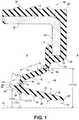
- Figure 1illustrates a radial shaft seal, referred to hereafter as seal 10, constructed in accordance with one aspect of the invention, wherein the seal is suitable for use in a crankcase application, by way of example and without limitation, for sealing about a rotatable shaft 12 in a radial shaft seal assembly 13 ( Figures 2-4 ) extending through a bore 14 in the crankcase 16 in which the seal 10 is installed.
- the seal 10can be installed into a carrier housing, whereupon the carrier housing and seal 10 can be attached to the engine.
- the seal 10has an oil side O and an axially opposite air side A, in relation to the orientation of the seal 10 when installed, with the oil side O facing to the interior of the crankcase 16 and the air side A facing to the outside environment.
- the seal 10includes a mounting portion, such as a case, also referred to as core or collar 18, provided as a metal annulus or ring structure with an elastomeric seal material 20 attached thereto.
- the seal material 20forms at least part of the an elastomeric seal body 22 with an axially extending seal lip 24 that exhibits low dynamic frictional contact with the shaft 12 during use, thereby resulting in a low torque between the shaft 12 and the seal lip 24, such as between about 0.07-0.35 N*m (Newton meters), as newly installed, during and upon use. Accordingly, as a result of the minimal frictional losses exhibited by the seal 10, the losses in efficiency of the engine are kept to a minimum.
- the metal collar 18may be L-shaped, as illustrated, or may take on any number of configurations, such as ring-shaped, C-shaped or S-shaped, depending upon the requirements of a particular application, as is know in the art.
- the L-shaped collar 18has a cylindrical outer wall 26 and a radially inwardly extending leg 28.
- the metal reinforcing ring structure 18is shown covered at least in part with the elastomeric seal material 20 on an outer surface of the outer wall 26 which may be contoured with undulations 30 to provide a snug and fluid tight installation in the bore 14 of the crankcase 16.
- the elastomeric seal material covering 20forms part of the elastomeric seal body 22 which is molded about the metal collar 18.
- the seal body 22extends along the radially inward extending leg 28 of the core 18 on the air side A and extends around an inner end 32 to cover a portion of the oil side O of the leg 28 and to provide a central portion 23 beneath the leg 28.
- the core 18 and seal body 22are relatively rigid, yet the seal material 20 is sufficiently resilient to form the seal lip 24.
- the sealing surface 34while in its free state, has a maximum diameter SD at the oil-side end 38 that is less than an outer diameter OD of a running surface 35 of the shaft 12, and thus, the entire sealing surface 34 is assured of being brought into sealing engagement with the running surface 35 upon completing assembly and in use.
- the sealing surface 35can be configured having hydrodynamic features 41 in the form of ribs or a thread, that act to pump oil back to the oil side O of the seal during rotation of the shaft.
- the air side end 40can be provided with a dust exclusion lip 39 that facilitates prevention of contamination ingress from the air-side A to the oil-side O of the seal assembly 10, and further, facilitates maintaining the lubricant on the oil-side O of the assembly 10.
- the seal lip 24is formed having a predetermined thickness t1 (shown only in Figure 1 to avoid cluttering the Figures, as with other dimensional features discussed hereafter) to facilitate maintaining the low-torque seal against the shaft 12, as is discussed in more detail below.
- An annular bridge 42operably connects the seal lip 24 to the seal body 22.
- the annular bridge 42is connected to the oil side end 38 of the seal lip 24 by a first hinge 44 and to the central portion 23 of the mounting portion 18 by a second hinge 46.
- the bridge 42extends over a length L1 along an imaginary line 45 that extends between and through the hinges 44, 46 at an angle to the horizontal central axis 33, such as between about 20-40 degrees, though the angle can range from 1-89 degrees from horizontal.
- the second hinge 46transitions to an orientation that is about parallel with the radial leg 28 of the mounting portion 18 and about perpendicular to a horizontal axis H of the seal 10.
- the bridge 42extends from the first hinge 44 to the second hinge 46 in radially overlying relation to the seal lip 24, and thus, provides an annular pocket 48 facing the air-side A of the seal assembly 10.
- the bridge 42is constructed having a thickness t2, while the first and second hinges 44, 46 are constructed having respective thickness t3, t4.
- the relative thicknessesare preferably such that t1 ⁇ t3; t2 ⁇ t3, and t2 ⁇ t4, and more preferably, t1 > t3; t2 > t3, and t2 > t4.
- the first hinge 44has a first diameter HID and the second hinge 46 has a second diameter H2D, wherein H1D ⁇ H2D.
- the seal 10further has a rib, also referred to as projection 50, that extends generally from the first hinge 44 axially away from the seal lip 24 and the bridge 42 toward the oil side O of the seal 10.
- the projection 50is configured to aid in the oil-side installation, discussed further below, to prevent the seal lip 24 and bridge 42 from unfolding during installation. Further, the projection 50 is configured to remain out of contact with the shaft running surface 35 upon assembly and during use. In the event the oil side O experiences a pressure change, such as a negative pressure (relative vacuum), the pressure differential across the seal exerts an axially inward force on the seal 10.
- the projections 50act at least in part to stiffen the seal lip 24, and thus, acts to prevent the seal lip 24 from lifting out of sealing contact from the shaft running surface 35.
- the projection 50has a thickness extending between an inner surface 52 and outer surface 54 that is sufficient to substantially retain its shape and geometry during installation without allowing the projection 50 to roll back or under itself.
- the inner surface 52is shown to gradually taper, and is further shown as having a convex contour, by way of example and without limitation, toward a free end 56.
- the inner surface 52has a minimum diameter PD that is at least slightly greater than the inner diameter of the sealing surface 34 of the seal lip 24, and thus, as mentioned, upon assembly on the shaft 12, the inner surface 52 is spaced radially outwardly out of contact from the running surface 35.
- the projection 50has a length L2 that extends generally from the first hinge 44 and/or the oil-side end 38 of the seal lip 24 that is sufficient to counter any forces tending to invert bridge 42, wherein the length L2 is less than the length L1 of the bridge 42.
- the projection 50acts primarily during installation as an aid to prevent the seal lip 24 from attaining an other than proper configuration on the shaft 12.
- the projection 50is formed substantially above the imaginary line 45, which further enhances the ability of the projection 50 to function as an "anti-inversion" feature for the seal bridge 42.
- the projection 50extends axially inwardly toward the oil-side O from an imaginary line 47 extending perpendicular to the imaginary line 45 through the first hinge 44.
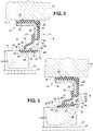
- Figures 2-4illustrate an oil-side installation progression of the shaft 12 through the seal 10, wherein a central axis 57 of the shaft 12 is slightly misaligned with the central axis 33 of the seal 10 ( Figures 2-3 ) and then coaxially aligned in Figure 4 .
- the seal 10is already installed into the housing 16, with the shaft 12 thereafter being extended into the bore 14 and through the seal 10.
- an end 58 of the shaft 12initially engages at least a portion of the projection inner surface 52.
- the end 58 of the shaft 12is configured to provide a lead-in tapered surface 60.
- the projection 50acts to bring the seal lip 24 into axial alignment with the shaft 12.
- the projection 50having its predetermined length L2 acts as a lever arm to counter any torsion forces generated by friction between the seal 10 and the shaft 12 from acting on the bridge 42, thereby preventing the bridge 42 from being rolled and inverted axially outwardly toward the air-side A of the seal 10. Accordingly, as shown in Figure 4 , upon full installation of the shaft 12 through the seal 10, the seal lip 24 attains its proper sealing configuration with the running surface 35 of the shaft 12.
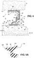
- Figure 5illustrates a seal 110 constructed in accordance with another aspect of the invention, with Figures 6-11 illustrating the seal 110 being installed in an oil-side installation progression on a shaft 112, wherein the same reference numerals as used above, offset by a factor of 100, are used to identify similar features as discussed above.
- the seal 110has a mounting portion, shown here, by way of example and without limitation, as having a rectangular metal reinforcing ring structure 118 in cross-section and an elastomeric seal material covering 120, wherein the covering 120 is shown as being molded to encapsulate the ring structure 118.
- the material covering 120is shown having an outer contoured surface with radially outwardly facing ribs for snug and fluid tight installation in a bore 114 of a housing 116.
- the elastomeric seal material 120provides a seal body 122 that extends radially inwardly of the core 118 to a central vertically extending body portion 123.
- the seal 110has a seal lip 124 and a bridge 142 with a first hinge 144 connecting the seal lip 124 to the bridge 142 and a second hinge 146 connecting the bridge 142 to the central portion 123 of the seal body 122.
- the relative thicknesses ( Figure 5 ) of the seal lip t1; bridge t2 and the first and second hinges t3, t4, respectively,are as discussed above. Further, the relative diameters H1D, H2D of the first and second hinges 144, 146 also remain as discussed above. Accordingly, thus far, other than the configuration of the mounting portion 118, the seal 110 is the same as the seal 10.
- the projection 150extends from a more radially outward location than the previously discussed projection 50, however, the projections 50, 150 remain similarly shaped.
- the projection 150extends generally from the first hinge 144 axially away from the seal lip 124 and the bridge 142 toward the oil side O of the seal 110, however, in slight contrast to the previous embodiment, it extends from a radially outward location relative to the first hinge 144.
- the projection 150has a thickness extending between an inner surface 152 and outer surface 154 that is sufficient to substantially retain its shape and geometry during installation without allowing the projection 150 to roll under or back on itself.
- the inner surface 152is gradually tapered to diverge radially outwardly, and is further shown as having a convex contour extending radially outwardly toward a free end 156.
- the inner surface 152has a minimum diameter PD that is at least slightly greater than the inner diameter of a sealing surface 134 of the seal lip 124, and thus, as discussed above with regard to the projection 50, upon assembly on the shaft 112, the inner surface 152 is spaced radially outwardly out of contact from the shaft running surface 135.
- the projection upper or outer surface 154extends in a smooth transition from the bridge 142 a sufficient length L2 to counter any forces tending to invert bridge 142, wherein the length L2 is less than the length L1 of the bridge 142.
- the projection 150acts primarily during installation to prevent the seal lip 124 from attaining an other than proper configuration on the shaft 112. Further, even more so than the projection 50, the projection 150 is formed entirely above an imaginary line 145 extending between the first and second hinges 144, 146, which further enhances the ability of the projection 150 to function as an "anti-inversion" lever arm feature for the seal bridge 142.
- the projection 150extends axially inwardly toward the oil-side O from an imaginary line 147 extending perpendicular to the imaginary line 145 through the first hinge 144.
- the dimensional aspects of the projection 150including its inside diameter, thickness and length provide its ability to prevent the bridge 142 from becoming inverted during assembly.
- Figure 5Aillustrates the seal 110 having a stiffening member 49 extending circumferentially through the projection 150, wherein the stiffening member 49 is formed of a relatively stiffer material from the seal material 120.
- the stiffening member 49can be formed of metal, e.g. wire, plastic, or a different, stiffer rubber material from the seal material. Accordingly, the stiffening member adds radial stiffness to the projection 150.
- FIGS 6-11illustrate an oil-side installation progression of the shaft 112 through the seal 110, wherein a central axis 157 of the shaft 112 is coaxially aligned with the central axis 133 of the seal 110.
- the seal 110is already installed into the housing 116, with the shaft 112 thereafter being extended into the bore 114 and through the seal 110.
- a tapered end 158 of the shaft 112initially engages the oil-side end 138 of the seal lip 124. This occurs because the inner surface 152 of the projection 150, having a larger diameter than the shaft 112, is radially outward from the shaft 112, and thus, does not make initial contact with the shaft 112.
- the engagement of the end 138 of the seal lip 124 with the end 158 of the shaft 112causes the seal lip 124 to pitch radially outwardly, such that the pocket 148 is caused to partially collapse, while simultaneously causing the projection to pitch radially inwardly.
- This pitching motionsare free to continue until the inner surface 152 of the projection 150 engages the outer surface of the shaft 112, whereupon the stiffness of the projection 150 substantially prevents any further pitching.
- the inner surface 152is caused to slide along the shaft 112, as shown in the series of progression views, until the sealing surface 134 is fully received on the shaft 112, at which time, the inner surface 152 of the projection moves out of circumferential contact from the shaft 112.
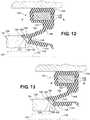
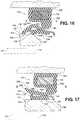
- Figures 12-18illustrate an oil-side installation progression of the shaft 112 through the seal 110 that follows the same progression as described for Figures 6-11 , however, the central axis 157 of the shaft 112 is axially misaligned with the central axis 133 of the seal 110.
- a tapered end 158 of the shaft 112initially engages the inner surface 152 projection 150, which slides along the tapered end 158 until it contacts the running surface 135 and the end 138 of the seal lip 124 engages the end 158 of the shaft 112.
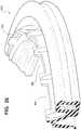
- Figures 19 and 20illustrate a seal 210 constructed in accordance with another aspect of the invention, with Figures 21-23 illustrating the seal 210 being installed in an oil-side installation progression on a shaft 212, wherein the same reference numerals as used above, offset by a factor of 200, are used to identify similar features as discussed above.
- the seal 210is constructed generally the same as discussed above with regard to Figure 5 , including a mounting collar 218 contoured with radially outwardly facing ribs for snug and fluid tight installation in a bore 242 of the crankcase housing 216. Further, a seal body 222 extends radially inwardly from the core 218 to a central vertically extending body portion 223.
- the seal 210has a seal lip 224 and a bridge 242 with a first hinge 244 connecting the seal lip 224 to the bridge 242 and a second hinge 246 connecting the bridge 242 to the central portion 223 of the seal body 222.
- the relative thicknesses of the seal lip t1; bridge t2 and the first and second hinges t3, t4are as discussed above. Further, the relative diameters H1D, H2D of the first and second hinges 244, 246 also remain as discussed above. Accordingly, thus far, other than the configuration of the mounting portion 218 and the seal 210 is the same as the seal 110.
- a projection 250extends generally from the first hinge 244 and the bridge 242 toward the oil side O.
- the projection 250has a thickness extending between an inner surface 252 and outer surface 254, and is shaped generally the same as that discussed with regard to the previously discussed projections 50, 150.
- the inner surface 252has a minimum diameter PD that is greater than the maximum inner diameter of a sealing surface 234 of the seal lip 224, and thus, as discussed above with regard to the projection 50, upon assembly on the shaft 212, the inner surface 252 is spaced radially outwardly out of contact from the shaft running surface 235.
- the projection outer surface 254extends in a smooth transition from the bridge 242 a sufficient length L2 to counter any forces tending to invert bridge 242, wherein the length L2 is less than the length L1 of the bridge 242, as discussed with regard to seal 110.
- seal 210The notable distinction between the seal 210 and the previously discussed seal 110 can be seen with the addition of a pluralist of stiffening ribs 60 molded as one piece of material with the seal body 222.
- the ribs 60facilitate assembly and to maintain a sealing surface 234 of the seal lip 224 in proper sealing relation with the running surface 235 of the shaft 212 during and upon assembly.
- the ribs 60extend axially along the bridge 242, and are shown here as extending along the upper or outer surface 254 of the projection 250 and along the full length of the bridge 242 and terminating at the central body portion 223 of the seal body 222.
- the ribs 60can be provided in any suitable number sufficient to prevent reverse folding of the bridge 242 and the main seal lip 224 during assembly, and is shown in Figure 19 , by way of example and without limitation, as being about 60 ribs.
- Each rib 60is spaced radially from an adjacent rib 60, with the ribs 60 being spaced equidistant from one another about the circumference of the seal body 222.
- the height of the ribs 60is such that an uppermost surface 62 of the ribs 60 remain spaced from the seal body 222 upon being assembled. As such, the ribs 60 do not interfere with the ability of the second hinge 246 to flex in use.
- An oil side installation progression of the shaft 212 through the seal 210is generally the same as discussed with regard to Figures 6-11 for a co-axially aligned installation, and the same as discussed with regard to Figures 12-18 for an axially misaligned installation.
- the seal assembly 110is moved axially onto to the shaft 212, and when the inner surface 252 of the projections 250 engage the shaft 212, the ribs 60 are placed under slight tension and act to prevent the seal lip 224 and bridge 242 from inverting and unfolding.
- the ribs 60add rigidity to the projection 250, which further enhances the ability of the seal lip 224 to be maintained in sealing engagement with the shaft 212, such as when a vacuum is established on the oil-side O of the seal 210. As such, the seal lip 224 is assured of being maintained in a proper sealing orientation on the shaft 212 during and upon completion of the assembly process.
- Figure 24illustrate a portion of a seal 310 constructed in accordance with another aspect of the invention, wherein the same reference numerals as used above, offset by a factor of 300, are used to identify similar features as discussed above.
- the seal 310is similar to the seal 210, wherein all the features are the same with the exception that a plurality of gaps 64 extend axially into a projection 350, thereby providing a plurality of radially spaced projections 350 spaced radially from one another by the gaps 64.
- the gaps 64 and projections 350are provided in uniformly spaced relation and size, thereby providing the seal 350 having a circumferentially symmetric appearance.
- the gaps 64extend axially from an oil-side end 238 of the seal lip 224 through to free ends 256 of adjacent projections 350. In the embodiment shown in Figure 24 , the gaps 64 occupy about 20 percent of the total circumference (gaps 64 + projections 350) of the seal body 322.
- each of the projections 350have one of the ribs 360 extending centrally thereon to enhance their axial stiffness, though it should be recognized that few ribs could be used, depending on the application, thereby leaving at least some of the projections 350 without ribs.
- Figure 25illustrates a portion of a seal 410 constructed in accordance with another aspect of the invention, wherein the same reference numerals as used above, offset by a factor of 400, are used to identify similar features as discussed above.
- the seal 410is similar to the seal 310, however, a plurality of gaps 464 occupy about 50 percent of the total circumference (gaps 464 + projections 450) of the seal body 422. Otherwise, the construction is the same.
- Figure 26illustrates a portion of a seal 510 constructed in accordance with another aspect of the invention, wherein the same reference numerals as used above, offset by a factor of 500, are used to identify similar features as discussed above.
- the seal 510is similar to the seal 410, however, a plurality of gaps 564 occupy about 66 percent of the total circumference (gaps 564 + projections 550) of the seal body 522. Otherwise, the construction is the same.
- Figure 27is a plot of three different seals constructed in accordance with Figure 5 assembled on a shaft and tested over a range of rpm's for a specified period of time. The torque was measured and recorded as indicated by the vertical axis, while the rpm and time duration thereof is indicated along the horizontal axis. As can be seen, the initial torque of the new seals started out at about 0.27 N*m, with one being initially higher at about 0.37 N*m, with the torque then becoming reduced as the time and rpm increased, lowering to between about 0.07 to 0.15 N*m. Accordingly, the seals demonstrated a low initial torque "as new", while providing an even lower torque upon run-in.
- the sealswere provided having a nominal running surface diameter at the oil-side end of 96.72 mm (+/- 0.38 mm) and a nominal running surface diameter at the air-side end of 96.01 mm (+/- 0.38 mm).
- the shaftwas provided having a nominal running surface diameter of 98.00 mm (+/- 0.05 mm).
- the maximum interference between the shaft and the seal lipis about 2.42 mm at the diameter at the air-side end of the seal lip and about 1.71 mm on the diameter at the oil-side end of the seal lip.
- the minimum interference between the shaft and the seal lipis about 1.56 mm on the diameter at the air-side end of the seal lip and about 0.85 mm on the diameter at the oil-side end of the seal lip.
Landscapes
- Engineering & Computer Science (AREA)
- General Engineering & Computer Science (AREA)
- Mechanical Engineering (AREA)
- Ocean & Marine Engineering (AREA)
- Sealing With Elastic Sealing Lips (AREA)
Description
- This invention relates generally to dynamic oil seals of the type for creating a fluid tight seal between a rotating shaft and a housing.
- Dynamic radial shaft oil seals are designed to have a so-called "oil side" of the seal and an "air side." These designations pertain to the orientation of the seal when installed, with the oil side facing the interior of the housing and in communication with the oil, whereas the air side faces outwardly and is exposed to the air.
- There are at least two different ways in which a radial shaft oil seal can be installed. An "air side installation" is one in which the seal is first installed into the bore of the housing and the shaft (or its wear sleeve) thereafter installed from the air side axially into the seal assembly (in the direction inward of the housing) to effect the seal. An "oil side installation" is the other where the housing and shaft are already present and the seal assembly is slid axially into the housing and simultaneously onto the shaft (or its wear sleeve), such that the shaft enters the seal assembly from the oil side of the seal. Otherwise, "oil-side" installation requires the seal assembly to be installed into the housing, also referred to as carrier, and then the housing, with seal installed therein, is assembled to an engine over the "all ready in place" shaft.
- During installation, regardless of the type, the seals must be able to withstand the axial loads resulting during installation without causing a seal lip of the seal to reverse fold or otherwise become displaced to a position where the seal lip is ineffective in the fully installed condition.
- Radial shaft seals are also subject to varying axial pressures that can be seen during leak testing or in use The pressure differential developed across the seal (between the oil and air side of the seal) can impart an axial load on the seal in one direction or the other (a vacuum or increased pressure in the housing) and can cause the seal to pull away from the shaft to at least some degree, and in extreme cases can cause the seal to reverse fold and collapse under the pressure so that the seal is broken
- A radial shaft seal that is able to be used even under kondidtios of high excentricity of the shaft with respect to a housing or in case of a highly excentric shaft is disclosed in the japanese patent application
JP 2006 226489 A - In general terms, this invention provides a radial shaft seal assembly with the features of
claim 1, a radial shaft seal assembly with the features of claim 8 and a method of installing a radial shaft seal with the features of claim 11 and wherein advantageous embodiments are disclosed in the dependent claims. This invention provides a radial shaft seal assembly having features that facilitate making a proper oil side installation, even in conditions of shaft-to-bore misalignment, and further, provide support for a seal lip of the seal assembly against adverse seal-breaking movement when exposed to positive or negative pressure on an oil side of the seal assembly when installed - In accordance with one presently preferred aspect of the invention, a radial shaft seal configured for receipt in a housing and about a shaft to sealingly isolate an air side of the shaft seal from an oil side of the shaft seal is provided The radial shaft seal includes an annular mounting portion and a seal lip having an annular sealing surface extending between an oil side end and a free air side end, with the sealing surface being configured to extend axially relative to the shaft Further, an annular bridge is connected to the oil side end of the seal lip by a first hinge and to the mounting portion by a second hinge The bridge extends from the first hinge to the second hinge m radially overlying relation to the seal lip At least one projection extends from the first hinge away from the bridge toward the oil side of the seal The projection prevents the seal lip from inverting during the oil-side installation process, thereby ensuring that the seal lip attains its proper sealing contact with a running surface duπng use
- In accordance with another aspect of the invention, a radial shaft seal assembly is provided The radial shaft seal assembly includes a shaft extending along a central axis and providing a running surface with a predetermined diameter and a radial shaft seal configured for receipt in a housing and about the shaft to sealingly isolate an air side of the radial shaft seal from an oil side of the radial shaft seal The radial shaft seal includes an annular mounting portion and a seal lip having an annular sealing surface and an opposite backing surface extending between an oil side end and a free air side end, with the sealing surface being configured to extend axially in dynamic sealing contact with the running surface. Further, an annular bridge is attached to the oil side end of the seal lip by a first hinge and to the mounting portion by a second hinge. The bridge extends from the first hinge to the second hinge in radially overlying relation to the seal lip. In addition, at least one projection extends axially from the first hinge toward the oil side of the seal.
- In accordance with another aspect of the invention, a method of installing a radial shaft seal onto a shaft is provided. The method includes providing a shaft having a running surface and providing the radial shaft seal with a seal lip having an annular sealing surface converging from an oil side end to a free air side end while in a free state. Further, providing the radial shaft seal with an annular bridge attached to the oil side end by a first hinge with the bridge diverging to a second hinge while in the free state. The second hinge being attached to an outer mounting portion such that the bridge extends in radially overlying relation with the seal lip. The radial shaft seal further including at least one projection extending axially from the first hinge toward an oil side of the seal. Then,
moving the shaft and the radial shaft seal axially toward one another and bringing the oil side end of the seal lip into abutment with an end of the shaft. Further, bringing the projection into abutment with running surface of the shaft and bringing the sealing surface into sealing engagement with the running surface while simultaneously moving the projection out of abutment with the running surface. - These and other aspects, features and advantages of the invention will become more readily appreciated when considered in connection with the following detailed description of presently preferred embodiments and best mode, appended claims and accompanying drawings, in which:
Figure 1 is a cross-sectional view of a radial shaft seal constructed according to one aspect of the invention;Figure 2-4 are cross-sectional views of the seal ofFigure 1 shown disposed in a housing with a shaft being installed in progression from an oil-side of the seal;Figure 5 is a cross-sectional view of a radial shaft seal constructed according to another aspect of the invention;Figure 5A is a partial cross-sectional view taken generally from theencircled area 5A ofFigure 5 showing a radial shaft seal construction in accordance with another aspect of the invention;Figures 6-11 illustrate cross-sectional views of the seal ofFigure 5 shown disposed in a housing with a shaft being installed in progression from an oil-side of the seal in co-axially aligned relation with the seal;Figures 12-18 illustrate cross-sectional views of the seal ofFigure 5 shown disposed in a housing with a shaft being installed in progression from an oil-side of the seal in axially misaligned relation with the seal;Figure 19 is a plan view of a radial shaft seal constructed according to another aspect of the invention;Figure 20 is a cross-sectional view taken generally along the line 20-20 ofFigure 19 ;Figures 21-23 are cross-sectional views of the seal ofFigure 20 shown disposed in a housing with a shaft being installed in progression from an oil-side of the seal;Figure 24 is a partial perspective view of a radial shaft seal constructed according to another aspect of the invention;Figure 25 is a partial perspective view of a radial shaft seal constructed according to another aspect of the invention;Figure 26 is a partial perspective view of a radial shaft seal constructed according to another aspect of the invention; andFigure 27 is a plot of running torque versus rpm for predetermined periods of time of three seals constructed in accordance with the invention.- Referring in more detail to the drawings,
Figure 1 illustrates a radial shaft seal, referred to hereafter asseal 10, constructed in accordance with one aspect of the invention, wherein the seal is suitable for use in a crankcase application, by way of example and without limitation, for sealing about arotatable shaft 12 in a radial shaft seal assembly 13 (Figures 2-4 ) extending through abore 14 in thecrankcase 16 in which theseal 10 is installed. Otherwise, theseal 10 can be installed into a carrier housing, whereupon the carrier housing andseal 10 can be attached to the engine. Theseal 10 has an oil side O and an axially opposite air side A, in relation to the orientation of theseal 10 when installed, with the oil side O facing to the interior of thecrankcase 16 and the air side A facing to the outside environment. Theseal 10 includes a mounting portion, such as a case, also referred to as core orcollar 18, provided as a metal annulus or ring structure with anelastomeric seal material 20 attached thereto. Theseal material 20 forms at least part of the anelastomeric seal body 22 with an axially extendingseal lip 24 that exhibits low dynamic frictional contact with theshaft 12 during use, thereby resulting in a low torque between theshaft 12 and theseal lip 24, such as between about 0.07-0.35 N*m (Newton meters), as newly installed, during and upon use. Accordingly, as a result of the minimal frictional losses exhibited by theseal 10, the losses in efficiency of the engine are kept to a minimum. - The
metal collar 18 may be L-shaped, as illustrated, or may take on any number of configurations, such as ring-shaped, C-shaped or S-shaped, depending upon the requirements of a particular application, as is know in the art. The L-shaped collar 18 has a cylindricalouter wall 26 and a radially inwardly extendingleg 28. The metal reinforcingring structure 18 is shown covered at least in part with theelastomeric seal material 20 on an outer surface of theouter wall 26 which may be contoured withundulations 30 to provide a snug and fluid tight installation in thebore 14 of thecrankcase 16. The elastomeric seal material covering 20 forms part of theelastomeric seal body 22 which is molded about themetal collar 18. Theseal body 22 extends along the radially inward extendingleg 28 of thecore 18 on the air side A and extends around aninner end 32 to cover a portion of the oil side O of theleg 28 and to provide acentral portion 23 beneath theleg 28. Thecore 18 andseal body 22 are relatively rigid, yet theseal material 20 is sufficiently resilient to form theseal lip 24. - The
seal lip 24, when in the relaxed, uninstalled state (Figure 1 ), extends slightly angled by a few degrees, such as between about 1-10 degrees from a horizontalcentral axis 33 of theseal 10 and has an annular, radially inwardly facingsealing surface 34 and an opposite, radially outwardly facingbacking surface 36 extending between anoil side end 38 and a freeair side end 40. Thesealing surface 34, while in its free state, has a maximum diameter SD at the oil-side end 38 that is less than an outer diameter OD of a runningsurface 35 of theshaft 12, and thus, theentire sealing surface 34 is assured of being brought into sealing engagement with the runningsurface 35 upon completing assembly and in use. The sealingsurface 35 can be configured havinghydrodynamic features 41 in the form of ribs or a thread, that act to pump oil back to the oil side O of the seal during rotation of the shaft. Further, theair side end 40 can be provided with adust exclusion lip 39 that facilitates prevention of contamination ingress from the air-side A to the oil-side O of theseal assembly 10, and further, facilitates maintaining the lubricant on the oil-side O of theassembly 10. Theseal lip 24 is formed having a predetermined thickness t1 (shown only inFigure 1 to avoid cluttering the Figures, as with other dimensional features discussed hereafter) to facilitate maintaining the low-torque seal against theshaft 12, as is discussed in more detail below. - An
annular bridge 42 operably connects theseal lip 24 to theseal body 22. Theannular bridge 42 is connected to theoil side end 38 of theseal lip 24 by afirst hinge 44 and to thecentral portion 23 of the mountingportion 18 by asecond hinge 46. Thebridge 42 extends over a length L1 along animaginary line 45 that extends between and through thehinges central axis 33, such as between about 20-40 degrees, though the angle can range from 1-89 degrees from horizontal. Thesecond hinge 46 transitions to an orientation that is about parallel with theradial leg 28 of the mountingportion 18 and about perpendicular to a horizontal axis H of theseal 10. Thebridge 42 extends from thefirst hinge 44 to thesecond hinge 46 in radially overlying relation to theseal lip 24, and thus, provides anannular pocket 48 facing the air-side A of theseal assembly 10. Thebridge 42 is constructed having a thickness t2, while the first and second hinges 44, 46 are constructed having respective thickness t3, t4. The relative thicknesses are preferably such that t1 ≥t3; t2 ≥t3, and t2 ≥t4, and more preferably, t1 > t3; t2 > t3, and t2 > t4. In addition, while in the free state, thefirst hinge 44 has a first diameter HID and thesecond hinge 46 has a second diameter H2D, wherein H1D < H2D. - The
seal 10 further has a rib, also referred to asprojection 50, that extends generally from thefirst hinge 44 axially away from theseal lip 24 and thebridge 42 toward the oil side O of theseal 10. Theprojection 50 is configured to aid in the oil-side installation, discussed further below, to prevent theseal lip 24 andbridge 42 from unfolding during installation. Further, theprojection 50 is configured to remain out of contact with theshaft running surface 35 upon assembly and during use. In the event the oil side O experiences a pressure change, such as a negative pressure (relative vacuum), the pressure differential across the seal exerts an axially inward force on theseal 10. Theprojections 50 act at least in part to stiffen theseal lip 24, and thus, acts to prevent theseal lip 24 from lifting out of sealing contact from theshaft running surface 35. Theprojection 50 has a thickness extending between aninner surface 52 andouter surface 54 that is sufficient to substantially retain its shape and geometry during installation without allowing theprojection 50 to roll back or under itself. To facilitate smooth installation, theinner surface 52 is shown to gradually taper, and is further shown as having a convex contour, by way of example and without limitation, toward afree end 56. Theinner surface 52 has a minimum diameter PD that is at least slightly greater than the inner diameter of the sealingsurface 34 of theseal lip 24, and thus, as mentioned, upon assembly on theshaft 12, theinner surface 52 is spaced radially outwardly out of contact from the runningsurface 35. Theprojection 50 has a length L2 that extends generally from thefirst hinge 44 and/or the oil-side end 38 of theseal lip 24 that is sufficient to counter any forces tending to invertbridge 42, wherein the length L2 is less than the length L1 of thebridge 42. As such, theprojection 50 acts primarily during installation as an aid to prevent theseal lip 24 from attaining an other than proper configuration on theshaft 12. As further shown inFigure 1 , theprojection 50 is formed substantially above theimaginary line 45, which further enhances the ability of theprojection 50 to function as an "anti-inversion" feature for theseal bridge 42. In addition, theprojection 50 extends axially inwardly toward the oil-side O from animaginary line 47 extending perpendicular to theimaginary line 45 through thefirst hinge 44. Figures 2-4 illustrate an oil-side installation progression of theshaft 12 through theseal 10, wherein acentral axis 57 of theshaft 12 is slightly misaligned with thecentral axis 33 of the seal 10 (Figures 2-3 ) and then coaxially aligned inFigure 4 . In this installation, theseal 10 is already installed into thehousing 16, with theshaft 12 thereafter being extended into thebore 14 and through theseal 10. As theshaft 12 is slid axially into thebore 14, anend 58 of theshaft 12 initially engages at least a portion of the projectioninner surface 52. To facilitate assembly, theend 58 of theshaft 12 is configured to provide a lead-intapered surface 60. With theshaft 12 and seal 10 being axially misaligned, it should be recognized that the diametrically opposite sides (not shown) of the seal and shaft are shifted relative to one another accordingly, and thus, a slight gap could result initially between theshaft 12 andprojection 50. As shown inFigure 3 , as theshaft 12 progresses axially though theseal 10, a portion of the projectioninner surface 52 remains in contact with theshaft 12 as it slides over the shaft tapered lead-insurface 60 onto the runningsurface 35. As this is occurring, themain seal lip 24 is caused to expand radially outwardly and the air-side end 40 of theseal lip 24 is caused to pitch radially outwardly, such that thepocket 48 is caused to partially collapse, thereby reducing the axial installation force required to install theseal 10 about theshaft 12. As such, theprojection 50 acts to bring theseal lip 24 into axial alignment with theshaft 12. In addition, aside from bringing theseal lip 24 into axial alignment with theshaft 12, theprojection 50, having its predetermined length L2, acts as a lever arm to counter any torsion forces generated by friction between theseal 10 and theshaft 12 from acting on thebridge 42, thereby preventing thebridge 42 from being rolled and inverted axially outwardly toward the air-side A of theseal 10. Accordingly, as shown inFigure 4 , upon full installation of theshaft 12 through theseal 10, theseal lip 24 attains its proper sealing configuration with the runningsurface 35 of theshaft 12.Figure 5 illustrates aseal 110 constructed in accordance with another aspect of the invention, withFigures 6-11 illustrating theseal 110 being installed in an oil-side installation progression on ashaft 112, wherein the same reference numerals as used above, offset by a factor of 100, are used to identify similar features as discussed above. As discussed above, theseal 110 has a mounting portion, shown here, by way of example and without limitation, as having a rectangular metal reinforcingring structure 118 in cross-section and an elastomeric seal material covering 120, wherein the covering 120 is shown as being molded to encapsulate thering structure 118. Similarly as discussed above, the material covering 120 is shown having an outer contoured surface with radially outwardly facing ribs for snug and fluid tight installation in a bore 114 of a housing 116.- The
elastomeric seal material 120 provides aseal body 122 that extends radially inwardly of the core 118 to a central vertically extendingbody portion 123. Similarly as in theseal 10 discussed above, theseal 110 has aseal lip 124 and abridge 142 with afirst hinge 144 connecting theseal lip 124 to thebridge 142 and asecond hinge 146 connecting thebridge 142 to thecentral portion 123 of theseal body 122. The relative thicknesses (Figure 5 ) of the seal lip t1; bridge t2 and the first and second hinges t3, t4, respectively, are as discussed above. Further, the relative diameters H1D, H2D of the first andsecond hinges portion 118, theseal 110 is the same as theseal 10. - The notable distinction between the
seal 110 and the previously discussedseal 10 can be seen with the location of aprojection 150 on theseal 110. With regard to theseal 110, theprojection 150 extends from a more radially outward location than the previously discussedprojection 50, however, theprojections projection 150 extends generally from thefirst hinge 144 axially away from theseal lip 124 and thebridge 142 toward the oil side O of theseal 110, however, in slight contrast to the previous embodiment, it extends from a radially outward location relative to thefirst hinge 144. As with the previously discussedprojection 50, theprojection 150 has a thickness extending between aninner surface 152 andouter surface 154 that is sufficient to substantially retain its shape and geometry during installation without allowing theprojection 150 to roll under or back on itself. To facilitate smooth installation, theinner surface 152 is gradually tapered to diverge radially outwardly, and is further shown as having a convex contour extending radially outwardly toward afree end 156. Theinner surface 152 has a minimum diameter PD that is at least slightly greater than the inner diameter of a sealingsurface 134 of theseal lip 124, and thus, as discussed above with regard to theprojection 50, upon assembly on theshaft 112, theinner surface 152 is spaced radially outwardly out of contact from theshaft running surface 135. The projection upper orouter surface 154 extends in a smooth transition from the bridge 142 a sufficient length L2 to counter any forces tending to invertbridge 142, wherein the length L2 is less than the length L1 of thebridge 142. As such, as with theprojection 50 discussed above, theprojection 150 acts primarily during installation to prevent theseal lip 124 from attaining an other than proper configuration on theshaft 112. Further, even more so than theprojection 50, theprojection 150 is formed entirely above animaginary line 145 extending between the first andsecond hinges projection 150 to function as an "anti-inversion" lever arm feature for theseal bridge 142. In addition, theprojection 150 extends axially inwardly toward the oil-side O from animaginary line 147 extending perpendicular to theimaginary line 145 through thefirst hinge 144. As discussed above, the dimensional aspects of theprojection 150, including its inside diameter, thickness and length provide its ability to prevent thebridge 142 from becoming inverted during assembly. Figure 5A illustrates theseal 110 having a stiffeningmember 49 extending circumferentially through theprojection 150, wherein the stiffeningmember 49 is formed of a relatively stiffer material from theseal material 120. The stiffeningmember 49, by way of example and without limitation, can be formed of metal, e.g. wire, plastic, or a different, stiffer rubber material from the seal material. Accordingly, the stiffening member adds radial stiffness to theprojection 150.Figures 6-11 illustrate an oil-side installation progression of theshaft 112 through theseal 110, wherein acentral axis 157 of theshaft 112 is coaxially aligned with thecentral axis 133 of theseal 110. In this installation, theseal 110 is already installed into the housing 116, with theshaft 112 thereafter being extended into the bore 114 and through theseal 110. As theshaft 112 is slid axially into the bore 114, atapered end 158 of theshaft 112 initially engages the oil-side end 138 of theseal lip 124. This occurs because theinner surface 152 of theprojection 150, having a larger diameter than theshaft 112, is radially outward from theshaft 112, and thus, does not make initial contact with theshaft 112. The engagement of theend 138 of theseal lip 124 with theend 158 of theshaft 112 causes theseal lip 124 to pitch radially outwardly, such that the pocket 148 is caused to partially collapse, while simultaneously causing the projection to pitch radially inwardly. This pitching motions are free to continue until theinner surface 152 of theprojection 150 engages the outer surface of theshaft 112, whereupon the stiffness of theprojection 150 substantially prevents any further pitching. As such, theinner surface 152 is caused to slide along theshaft 112, as shown in the series of progression views, until the sealingsurface 134 is fully received on theshaft 112, at which time, theinner surface 152 of the projection moves out of circumferential contact from theshaft 112.Figures 12-18 illustrate an oil-side installation progression of theshaft 112 through theseal 110 that follows the same progression as described forFigures 6-11 , however, thecentral axis 157 of theshaft 112 is axially misaligned with thecentral axis 133 of theseal 110. As theshaft 112 is slid axially into the bore 114, atapered end 158 of theshaft 112 initially engages theinner surface 152projection 150, which slides along thetapered end 158 until it contacts the runningsurface 135 and theend 138 of theseal lip 124 engages theend 158 of theshaft 112. The engagement of theend 138 of theseal lip 124 with theend 158 of theshaft 112 causes theseal lip 124 to pitch radially outwardly, such that the pocket 148 is caused to partially collapse, while simultaneously causing the projection to pitch radially inwardly and maintain contact with the runningsurface 135. When theinner surface 152 is caused to slide along theshaft 112, as shown in the series of progression views, and fully received on theshaft 112, theinner surface 152 of the projection moves out of circumferential contact from theshaft 112.Figures 19 and20 illustrate aseal 210 constructed in accordance with another aspect of the invention, withFigures 21-23 illustrating theseal 210 being installed in an oil-side installation progression on ashaft 212, wherein the same reference numerals as used above, offset by a factor of 200, are used to identify similar features as discussed above. Theseal 210 is constructed generally the same as discussed above with regard toFigure 5 , including a mountingcollar 218 contoured with radially outwardly facing ribs for snug and fluid tight installation in abore 242 of thecrankcase housing 216. Further, aseal body 222 extends radially inwardly from thecore 218 to a central vertically extendingbody portion 223. Theseal 210 has aseal lip 224 and abridge 242 with afirst hinge 244 connecting theseal lip 224 to thebridge 242 and asecond hinge 246 connecting thebridge 242 to thecentral portion 223 of theseal body 222. The relative thicknesses of the seal lip t1; bridge t2 and the first and second hinges t3, t4 are as discussed above. Further, the relative diameters H1D, H2D of the first andsecond hinges portion 218 and theseal 210 is the same as theseal 110. In addition, aprojection 250 extends generally from thefirst hinge 244 and thebridge 242 toward the oil side O. Theprojection 250 has a thickness extending between aninner surface 252 andouter surface 254, and is shaped generally the same as that discussed with regard to the previously discussedprojections inner surface 252 has a minimum diameter PD that is greater than the maximum inner diameter of a sealing surface 234 of theseal lip 224, and thus, as discussed above with regard to theprojection 50, upon assembly on theshaft 212, theinner surface 252 is spaced radially outwardly out of contact from theshaft running surface 235. The projectionouter surface 254 extends in a smooth transition from the bridge 242 a sufficient length L2 to counter any forces tending to invertbridge 242, wherein the length L2 is less than the length L1 of thebridge 242, as discussed with regard to seal 110.- The notable distinction between the
seal 210 and the previously discussedseal 110 can be seen with the addition of a pluralist of stiffeningribs 60 molded as one piece of material with theseal body 222. Theribs 60 facilitate assembly and to maintain a sealing surface 234 of theseal lip 224 in proper sealing relation with the runningsurface 235 of theshaft 212 during and upon assembly. Theribs 60 extend axially along thebridge 242, and are shown here as extending along the upper orouter surface 254 of theprojection 250 and along the full length of thebridge 242 and terminating at thecentral body portion 223 of theseal body 222. Theribs 60 can be provided in any suitable number sufficient to prevent reverse folding of thebridge 242 and themain seal lip 224 during assembly, and is shown inFigure 19 , by way of example and without limitation, as being about 60 ribs. Eachrib 60 is spaced radially from anadjacent rib 60, with theribs 60 being spaced equidistant from one another about the circumference of theseal body 222. The height of theribs 60 is such that anuppermost surface 62 of theribs 60 remain spaced from theseal body 222 upon being assembled. As such, theribs 60 do not interfere with the ability of thesecond hinge 246 to flex in use. - An oil side installation progression of the
shaft 212 through theseal 210 is generally the same as discussed with regard toFigures 6-11 for a co-axially aligned installation, and the same as discussed with regard toFigures 12-18 for an axially misaligned installation. However, as theseal assembly 110 is moved axially onto to theshaft 212, and when theinner surface 252 of theprojections 250 engage theshaft 212, theribs 60 are placed under slight tension and act to prevent theseal lip 224 and bridge 242 from inverting and unfolding. Further, theribs 60 add rigidity to theprojection 250, which further enhances the ability of theseal lip 224 to be maintained in sealing engagement with theshaft 212, such as when a vacuum is established on the oil-side O of theseal 210. As such, theseal lip 224 is assured of being maintained in a proper sealing orientation on theshaft 212 during and upon completion of the assembly process. Figure 24 illustrate a portion of aseal 310 constructed in accordance with another aspect of the invention, wherein the same reference numerals as used above, offset by a factor of 300, are used to identify similar features as discussed above.- The
seal 310 is similar to theseal 210, wherein all the features are the same with the exception that a plurality ofgaps 64 extend axially into aprojection 350, thereby providing a plurality of radially spacedprojections 350 spaced radially from one another by thegaps 64. Thegaps 64 andprojections 350 are provided in uniformly spaced relation and size, thereby providing theseal 350 having a circumferentially symmetric appearance. Thegaps 64 extend axially from an oil-side end 238 of theseal lip 224 through to free ends 256 ofadjacent projections 350. In the embodiment shown inFigure 24 , thegaps 64 occupy about 20 percent of the total circumference (gaps 64 + projections 350) of the seal body 322. Thegaps 64 provide enhance radial flexibility to the individually spacedprojections 350 during assembly by allowing theprojections 350 to flex individually relative to one another, while theprojections 350 maintain their ability to prevent inversion of the bridge 342 and unfolding of the seal lip 324. In the embodiment shown, by way of example, each of theprojections 350 have one of theribs 360 extending centrally thereon to enhance their axial stiffness, though it should be recognized that few ribs could be used, depending on the application, thereby leaving at least some of theprojections 350 without ribs. Figure 25 illustrates a portion of aseal 410 constructed in accordance with another aspect of the invention, wherein the same reference numerals as used above, offset by a factor of 400, are used to identify similar features as discussed above. Theseal 410 is similar to theseal 310, however, a plurality ofgaps 464 occupy about 50 percent of the total circumference (gaps 464 + projections 450) of the seal body 422. Otherwise, the construction is the same.Figure 26 illustrates a portion of aseal 510 constructed in accordance with another aspect of the invention, wherein the same reference numerals as used above, offset by a factor of 500, are used to identify similar features as discussed above. Theseal 510 is similar to theseal 410, however, a plurality ofgaps 564 occupy about 66 percent of the total circumference (gaps 564 + projections 550) of the seal body 522. Otherwise, the construction is the same.Figure 27 is a plot of three different seals constructed in accordance withFigure 5 assembled on a shaft and tested over a range of rpm's for a specified period of time. The torque was measured and recorded as indicated by the vertical axis, while the rpm and time duration thereof is indicated along the horizontal axis. As can be seen, the initial torque of the new seals started out at about 0.27 N*m, with one being initially higher at about 0.37 N*m, with the torque then becoming reduced as the time and rpm increased, lowering to between about 0.07 to 0.15 N*m. Accordingly, the seals demonstrated a low initial torque "as new", while providing an even lower torque upon run-in. The seals were provided having a nominal running surface diameter at the oil-side end of 96.72 mm (+/- 0.38 mm) and a nominal running surface diameter at the air-side end of 96.01 mm (+/- 0.38 mm). The shaft was provided having a nominal running surface diameter of 98.00 mm (+/- 0.05 mm). As such, the maximum interference between the shaft and the seal lip is about 2.42 mm at the diameter at the air-side end of the seal lip and about 1.71 mm on the diameter at the oil-side end of the seal lip. Meanwhile, the minimum interference between the shaft and the seal lip is about 1.56 mm on the diameter at the air-side end of the seal lip and about 0.85 mm on the diameter at the oil-side end of the seal lip.- Obviously, many modifications and variations of the present invention are possible in light of the above teachings. It is, therefore, to be understood that within the scope of the appended claims the invention may be practiced otherwise than as specifically described.
Claims (13)
- A radial shaft seal (10) configured for receipt in a housing (16, 116, 216) and about a shaft (12, 112, 212) to sealingly isolate an air side (A) of the shaft seal from an oil side (O) of the shaft seal, comprising:an annular mounting portion (18, 118, 218);a seal lip (24, 124, 224) having an annular sealing surface (34, 134, 234) extending between an oil side end (38) and a free air side end (40), said sealing surface being configured to extend axially relative to the shaft (12, 112, 212);an annular bridge (42, 142, 242, 342) connected to said oil side end (38) of said seal lip (24, 124, 224) by a first hinge (44, 144, 244) and to said mounting portion (18, 118, 218) by a second hinge (46, 146, 246), said bridge (42, 142, 242, 342) extending from said first hinge (44, 144, 244) to said second hinge (46, 146, 246) in radially overlying relation to said seal lip (24, 124, 224); andbeingcharacterized byan annular projection (50, 150, 250, 350) extending from said mounting portion (18, 118, 218) axially away from said bridge (42, 142, 242, 342), and extending axially from the first hinge (44, 144, 244) toward an oil side (O) of the seal, said projection (50, 150, 250, 350) having an oil side facing said seal lip (24, 124, 224) and being configured to confront said air side end (40) of said seal lip (24, 124, 224) upon said seal lip (24, 124, 224) pivoting about said first hinge (44, 144, 244) toward said projection (50, 150, 250, 350), wherein a stiffening member (49) extends circumferentially through said projection (50, 150, 250, 350), adding radial stiffness to said projection (50, 150, 250, 350).
- The radial shaft seal (10) of claim 1 wherein said projection (50, 150, 250, 350) extends to an annular free end having a diameter greater than said seal lip (24, 124, 224).
- The radial shaft seal (10) of claim 1 wherein said first and second hinges (44, 144, 244, 46, 146, 246) each have a thickness and said seal lip (24, 124, 224) has a thickness that is greater than at least one of said thickness of said first hinge (44, 144, 244) and said second hinge (46, 146,246).
- The radial shaft seal (10) of claim 3 wherein said bridge (42, 142, 242, 342) has a thickness that is greater than at least one of said thickness of said first hinge (44, 144, 244) and said second hinge (46, 146, 246).
- The radial shaft seal (10) of claim 4 wherein said thickness of said seal lip (24, 124, 224) is greater than said thickness of said bridge (42, 142, 242, 342).
- The radial shaft seal (10) of claim 1 wherein said first and second hinges (44, 144, 244, 46, 146, 246) each have a thickness and said bridge (42, 142, 242, 342) has a thickness that is greater than said thickness of at least one of said first hinge (44, 144, 244) and said second hinge (46, 146, 246).
- The radial shaft seal (10) of claim 1 wherein said first hinge (44, 144, 244) extends between said seal lip (24, 124, 224) and said projection (50, 150, 250, 350).
- A radial shaft seal assembly, comprising:a shaft (12, 112, 212) extending along a central axis (57) and providing a running surface (35, 135, 235) with a predetermined diameter; anda radial shaft seal (10) configured for receipt in a housing (16, 116, 216) and about said shaft (12, 112, 212) to sealingly isolate an air side (A) of the radial shaft seal (10) from an oil side (O) of the radial shaft seal (10), comprising:an annular mounting portion (18, 118, 218);a seal lip (24, 124, 224) having an annular sealing surface (34, 134, 234) extending between an oil side end (38) and a free air side end (40), said sealing surface (34, 134, 234) being configured to extend axially in dynamic sealing contact with said running surface (35, 135, 235);an annular bridge (42, 142, 242, 342) connected to said oil side end (38) of said seal lip (24, 124, 224) by a first hinge (44, 144, 244) and to said mounting portion (18, 118, 218) by a second hinge (46, 146, 246), said bridge (42, 142, 242, 342) extending from said first hinge (44, 144, 244) to said second hinge (46, 146, 246) in radially overlying relation to said seal lip (24, 124, 224); andwherein the radial shaft seal assembly beingcharacterized in that the radial shaft seal (10) commprising:
an annular projection (50, 150, 250, 350) extending from said mounting portion (18, 118, 218) axially away from said bridge (42, 142, 242, 342) toward said running surface (35, 135, 235) extending axially from the first hinge (44, 144, 244) toward an oil side (O) of the seal, said projection (50, 150, 250, 350) having an oil side facing said seal lip (24, 124, 224) configured to confront said air side end (40) of said seal lip (24, 124, 224) upon said seal lip (24, 124, 224) pivoting about said second hinge (46, 146, 246) toward said projection (50, 150, 250, 350), wherein a stiffening member (49) extends circumferentially through the projection (50, 150, 250, 350), adding radial stiffness to said projection (50, 150, 250, 350). - The radial shaft seal assembly of claim 8 wherein said projection (50, 150, 250, 350) extends to an annular free end having a diameter greater than said shaft (12, 112, 212).
- The radial shaft seal assembly of claim 9 wherein said first hinge (44, 144, 244) has a thickness, said seal lip (24, 124, 224) and said bridge (42, 142, 242, 342) each having a thickness greater than said thickness of said first hinge (44, 144, 244).
- A method of installing a radial shaft seal (10) onto a shaft (12, 112, 212), comprising:providing a shaft (12, 112, 212) having a running surface (35, 135, 235);providing the radial shaft seal (10) with a seal lip (24, 124, 224) having an annular sealing surface (34, 134, 234) converging from an oil side end (38) to a free air side end (40) while in a free state with an annular bridge (42, 142, 242, 342) attached to the oil side end (38) by a first hinge (44, 144, 244) and diverging to a second hinge (46, 146, 246) while in the free state, the second hinge (46, 146, 246) being attached to an outer mounting portion (18, 118, 218) such that the bridge (42, 142, 242, 342) extends in radially overlying relation with the seal lip (24, 124, 224), wherein the seal ischaracterized by further including an annular projection (50, 150, 250, 350) extending from the mounting portion (18, 118, 218) axially away from the bridge (42, 142, 242, 342), and extending axially from the first hinge (44, 144, 244) toward an oil side (O) of the seal, the projection (50, 150, 250, 350) having an oil side facing the seal lip (24, 124, 224), and wherein a stiffening member (49) extends circumferentially through the projection (50, 150, 250, 350), adding radial stiffness to said projection (50, 150, 250, 350);moving the shaft (12, 112, 212) and the radial shaft seal (10) axially toward one another;bringing the oil side end (38) of the seal lip (24, 124, 224) into abutment with an end of the shaft (12, 112, 212) andwherein the method ischaracterized by causing the air-side end (40) of the seal lip (24, 124, 224) to move into abutment with the oil side of the projection (50, 150, 250, 350); andbringing the sealing surface (34, 134, 234) into sealing engagement with the running surface (35, 135, 235) and simultaneously moving the air side end (40) of the seal lip (24, 124, 224) out of abutment with the projection (50, 150, 250, 350).
- The method of claim 11 further including providing the projection (50, 150, 250, 350) with a predetermined length extending to a free end having a diameter greater than a diameter of the running surface (35, 135, 235).
- The method of claim 12 further including causing the sealing surface (34, 134, 234) to pivot at least in part via the first hinge (44, 144, 244) from the converging configuration to a diverging configuration.
Applications Claiming Priority (3)
| Application Number | Priority Date | Filing Date | Title |
|---|---|---|---|
| US14793809P | 2009-01-28 | 2009-01-28 | |
| US22636809P | 2009-07-17 | 2009-07-17 | |
| PCT/US2010/022349WO2010088344A2 (en) | 2009-01-28 | 2010-01-28 | Radial shaft seal, radial shaft seal assembly and method of installation |
Publications (3)
| Publication Number | Publication Date |
|---|---|
| EP2382407A2 EP2382407A2 (en) | 2011-11-02 |
| EP2382407A4 EP2382407A4 (en) | 2016-03-16 |
| EP2382407B1true EP2382407B1 (en) | 2018-10-24 |
Family
ID=42353543
Family Applications (2)
| Application Number | Title | Priority Date | Filing Date |
|---|---|---|---|
| EP10736383.0AActiveEP2382407B1 (en) | 2009-01-28 | 2010-01-28 | Radial shaft seal, radial shaft seal assembly and method of installation |
| EP10736382.2AActiveEP2382406B1 (en) | 2009-01-28 | 2010-01-28 | Radial shaft seal, radial shaft seal assembly and method of installation |
Family Applications After (1)
| Application Number | Title | Priority Date | Filing Date |
|---|---|---|---|
| EP10736382.2AActiveEP2382406B1 (en) | 2009-01-28 | 2010-01-28 | Radial shaft seal, radial shaft seal assembly and method of installation |
Country Status (7)
| Country | Link |
|---|---|
| US (2) | US8500130B2 (en) |
| EP (2) | EP2382407B1 (en) |
| JP (2) | JP5600689B2 (en) |
| KR (2) | KR101623752B1 (en) |
| CN (2) | CN102356258B (en) |
| BR (2) | BRPI1007285A2 (en) |
| WO (2) | WO2010088343A2 (en) |
Families Citing this family (27)
| Publication number | Priority date | Publication date | Assignee | Title |
|---|---|---|---|---|
| CN101878388B (en)* | 2007-11-28 | 2014-03-12 | Skf公司 | Seal |
| EP2382407B1 (en) | 2009-01-28 | 2018-10-24 | Federal-Mogul Corporation | Radial shaft seal, radial shaft seal assembly and method of installation |
| EP2400189B1 (en)* | 2010-06-25 | 2014-04-02 | Dichtungstechnik G. Bruss GmbH & Co. KG | Rotary shaft lip seal, use of same and method of producing same |
| US8950755B1 (en)* | 2010-09-24 | 2015-02-10 | The United States Of America As Represented By The Secretary Of The Navy | Watertight closure gasket insertion tool |
| US9062773B2 (en)* | 2011-03-08 | 2015-06-23 | Federal-Mogul Corporation | Radial shaft seal, radial shaft seal assembly and method of installation |
| KR101988267B1 (en)* | 2011-03-17 | 2019-06-12 | 테네코 인코퍼레이티드 | Low torque radial shaft seal assembly |
| US8459654B2 (en)* | 2011-05-03 | 2013-06-11 | Federal-Mogul Corporation | Hydrodynamic seal with increased flexibility sealing element |
| ITTO20110581A1 (en)* | 2011-07-01 | 2013-01-02 | Skf Ab | ANULAR SEALING COMPLEX, IN PARTICULAR FOR THE INTERPOSITION BETWEEN ELEMENTS SUBJECT TO DISTANCE |
| EP2554878B1 (en)* | 2011-08-03 | 2016-07-13 | Carl Freudenberg KG | Seal |
| US9175774B2 (en) | 2011-10-26 | 2015-11-03 | Federal-Mogul Corporation | Radial shaft seal, radial shaft seal assembly and method of installation |
| US8950753B2 (en)* | 2011-11-23 | 2015-02-10 | Federal-Mogul Corporation | Radial shaft seal, radial shaft seal assembly and method of installation |
| BR112014030240A2 (en)* | 2012-06-04 | 2017-06-27 | Federal Mogul Corp | radial shaft seal and mounting this |
| US9759330B2 (en)* | 2014-02-04 | 2017-09-12 | Freudenberg-Nok General Partnership | Energy saving seal with rocking dust lip |
| US9714710B2 (en)* | 2014-02-04 | 2017-07-25 | Freudenberg-Nok General Partnership | Energy saving self-contact seal with pushing bead |
| US9695937B2 (en)* | 2014-02-04 | 2017-07-04 | Freudenberg-Nok General Partnership | Energy saving seal with vacuum induced counter-balance and rocking feature |
| CN105465188B (en)* | 2014-07-10 | 2019-05-21 | 舍弗勒技术股份两合公司 | Bearing assembly |
| JP6426828B2 (en)* | 2015-03-18 | 2018-11-21 | Nok株式会社 | Sealing device |
| KR101674424B1 (en)* | 2015-05-29 | 2016-11-10 | (주)진양오일씰 | Low friction rotary shaft seal for automobile engine mission |
| JP6727002B2 (en)* | 2016-03-31 | 2020-07-22 | Ntn株式会社 | Bearing with seal |
| DE102016220179A1 (en)* | 2016-10-17 | 2018-04-19 | Aktiebolaget Skf | sealing arrangement |
| CA3064941A1 (en)* | 2017-06-13 | 2018-12-20 | Stemco Products, Inc. | Wheelend assembly seal |
| CN109307077B (en)* | 2017-07-27 | 2022-11-29 | 舍弗勒技术股份两合公司 | seal assembly |
| JP6986915B2 (en)* | 2017-09-29 | 2021-12-22 | キーパー株式会社 | Oil seal |
| KR102200569B1 (en)* | 2018-07-20 | 2021-01-08 | 평화오일씰공업 주식회사 | Spring-less oil seal |
| CN114224138B (en)* | 2022-02-23 | 2022-05-03 | 常州乐邦科技有限公司 | Intelligent display rack |
| DE102022202044A1 (en)* | 2022-02-28 | 2023-08-31 | Aktiebolaget Skf | Radial shaft seal |
| JPWO2024157877A1 (en)* | 2023-01-25 | 2024-08-02 |
Family Cites Families (60)
| Publication number | Priority date | Publication date | Assignee | Title |
|---|---|---|---|---|
| DE711737C (en)* | 1938-04-02 | 1941-10-06 | Kupfer Asbest Co | Ready-to-install, housing-less shaft seal for sealing against corrosive liquids and gases |
| US2635907A (en)* | 1950-11-13 | 1953-04-21 | Brummer Mfg Corp | Seal for shafts |
| US2743947A (en)* | 1952-01-07 | 1956-05-01 | Curtis D Foss | Journal box seal with floating sleeve |
| US2736586A (en)* | 1952-12-05 | 1956-02-28 | Gen Motors Corp | Fluid seal |
| US2743497A (en) | 1953-03-25 | 1956-05-01 | Davis Aircraft Products Inc | Slide buckle |
| US3941396A (en)* | 1974-08-15 | 1976-03-02 | Caterpillar Tractor Co. | Seal for rotating means |
| US4021049A (en)* | 1975-12-15 | 1977-05-03 | Caterpillar Tractor Co. | Adjustable lip type seal for a crankshaft |
| US4061346A (en)* | 1977-01-24 | 1977-12-06 | General Motors Corporation | Cup seal for use in a master cylinder |
| JPS55149659U (en)* | 1979-04-13 | 1980-10-28 | ||
| US4274641A (en)* | 1979-10-29 | 1981-06-23 | Garlock Inc. | Shaft seal and method |
| GB2121893B (en)* | 1981-10-21 | 1985-05-22 | Mitsubishi Rubber | Sealing arrangements for bearings |
| US4522411A (en)* | 1984-10-01 | 1985-06-11 | Chicago Rawhide Mfg. Co. | Fluid seals with self-venting auxiliary lips |
| US4588195A (en)* | 1985-11-22 | 1986-05-13 | Dana Corporation | Floating lip seal assembly with convoluted flexible section |
| DE3612420A1 (en) | 1986-04-12 | 1987-10-15 | Kaco Gmbh Co | Radial shaft sealing ring |
| DE3613220A1 (en) | 1986-04-18 | 1987-10-22 | Goetze Ag | Lip seal ring |
| JPS62258267A (en)* | 1986-05-02 | 1987-11-10 | Taiho Kogyo Co Ltd | Sealing device |
| US4968044A (en)* | 1987-12-14 | 1990-11-06 | P And C Engineering And Development | Rotary facial seal and bearing assembly |
| JPH01102570U (en)* | 1987-12-28 | 1989-07-11 | ||
| DE3807893C2 (en)* | 1988-03-10 | 1994-02-24 | Freudenberg Carl Fa | Seal for a magnetizable shaft |
| US4844484A (en)* | 1988-06-28 | 1989-07-04 | Dana Corporation | Floating lip seal with reinforced flexible portion |
| JPH0298266U (en) | 1989-01-23 | 1990-08-06 | ||
| JPH0743549Y2 (en)* | 1989-11-29 | 1995-10-09 | エヌオーケー株式会社 | Sealing device |
| JPH04107580U (en) | 1991-03-04 | 1992-09-17 | 光洋精工株式会社 | Oil seal |
| US5398942A (en)* | 1992-09-02 | 1995-03-21 | Dana Corporation | Annular lubricant seal assembly |
| JPH06193741A (en) | 1992-12-25 | 1994-07-15 | Toyota Motor Corp | Seal member |
| JP2585626Y2 (en)* | 1992-12-25 | 1998-11-25 | エヌオーケー株式会社 | Sealing device |
| JPH0814399A (en)* | 1994-07-01 | 1996-01-16 | Nok Corp | Oil seal |
| DE19642544A1 (en)* | 1996-10-15 | 1998-04-23 | Bruss Dichtungstechnik | Radial shaft sealing ring with PTFE sealing lip and method and device for its production |
| US6105968A (en)* | 1997-02-24 | 2000-08-22 | Massachusetts Institute Of Technology | Textured seal for reduced wear |
| US6029980A (en)* | 1997-09-18 | 2000-02-29 | Freudenberg-Nok General Partnership | Fluid side contamination exclusion sealing lip for radial shaft seals |
| US6601855B1 (en)* | 1998-10-12 | 2003-08-05 | Freudenberg Nok Gp | Seal for a universal joint |
| US6619664B1 (en)* | 1998-12-18 | 2003-09-16 | Caterpillar Inc | Wear improvement to textured lip seal |
| DE10033446C5 (en)* | 2000-07-10 | 2006-12-14 | Dichtungstechnik G. Bruss Gmbh & Co. Kg | Shaft seal |
| DE10109320C2 (en)* | 2001-02-27 | 2003-07-10 | Bruss Dichtungstechnik | Radial shaft seal |
| DE10117881A1 (en) | 2001-04-10 | 2002-11-21 | Freudenberg Carl Kg | Radial shaft seal |
| US20030006563A1 (en)* | 2001-06-20 | 2003-01-09 | Cater Brian B. | Rotary facial seal and bearing assembly with plastic ring |
| JP4129615B2 (en)* | 2001-08-08 | 2008-08-06 | Nok株式会社 | Sealing device |
| FR2832204B1 (en)* | 2001-11-14 | 2004-04-02 | Syegon | SEALING RING FOR A FLUID CIRCUIT |
| US6866271B2 (en)* | 2002-02-05 | 2005-03-15 | Duramax Marine, Llc | Marine shaft seal with lip seal, bearing and gasket |
| DE10208233B4 (en)* | 2002-02-26 | 2004-09-02 | Federal-Mogul Sealing Systems Bretten Gmbh & Co. Kg | Static sealing element for acoustically decoupled attachments |
| JP2003269616A (en) | 2002-03-19 | 2003-09-25 | Nsk Ltd | sticker |
| ATE371129T1 (en)* | 2002-11-11 | 2007-09-15 | Kaco Gmbh & Co Kg | DEVICE WITH A SEALING ARRANGEMENT |
| JP2004190782A (en)* | 2002-12-11 | 2004-07-08 | Komatsu Ltd | Sliding seal structure at shaft |
| JP4112503B2 (en)* | 2004-01-09 | 2008-07-02 | ファナック株式会社 | Multi-stage oil seal for machine tool motor |
| ZA200500982B (en)* | 2004-02-12 | 2005-10-26 | Weir Minerals Africa ( Pty ) Ltd | Sealing between components of a rotary machine |
| JP2005240932A (en)* | 2004-02-27 | 2005-09-08 | Nok Corp | Sealing device |
| US20060103075A1 (en)* | 2004-11-15 | 2006-05-18 | Zahn Henry W | Triple lip fork seal |
| JP4739745B2 (en)* | 2004-12-21 | 2011-08-03 | Nok株式会社 | Sealing device with sound insulation seal |
| JP4662031B2 (en)* | 2005-02-21 | 2011-03-30 | Nok株式会社 | Sealing device |
| US7854432B2 (en)* | 2005-02-24 | 2010-12-21 | Freudenberg-Nok General Partnership | Dynamic seal |
| US7464942B2 (en)* | 2005-06-15 | 2008-12-16 | Federal-Mogulk World Wide, Inc. | Shaft seal having independent sealing lips |
| US8480092B2 (en)* | 2005-09-12 | 2013-07-09 | Federal-Mogul World Wide, Inc. | Radial seal and method of making |
| JP4849235B2 (en) | 2006-09-19 | 2012-01-11 | Nok株式会社 | Sealing device |
| WO2008062585A1 (en)* | 2006-11-21 | 2008-05-29 | Nok Corporation | Sealing device |
| US8052152B2 (en)* | 2007-03-09 | 2011-11-08 | Federal-Mogul Corporation | Dynamic shaft seal and method of installation thereof |
| EP1992849B1 (en)* | 2007-05-15 | 2016-12-21 | Carl Freudenberg KG | Sealing arrangement |
| US7963526B2 (en)* | 2007-05-15 | 2011-06-21 | Freudenberg-Nok General Partnership | Prelubricated multi-lipped radial shaft seal with large radial offset accommodation |
| JP2009002510A (en)* | 2007-06-15 | 2009-01-08 | Dichtungstechnik G Bruss Gmbh & Co Kg | Sealing member for shaft and vehicle component |
| EP2382407B1 (en)* | 2009-01-28 | 2018-10-24 | Federal-Mogul Corporation | Radial shaft seal, radial shaft seal assembly and method of installation |
| US8590903B2 (en)* | 2009-03-24 | 2013-11-26 | Freudenberg-Nok General Partnership | Lip seal with inversion prevention feature |
- 2010
- 2010-01-28EPEP10736383.0Apatent/EP2382407B1/enactiveActive
- 2010-01-28KRKR1020117019553Apatent/KR101623752B1/ennot_activeExpired - Fee Related
- 2010-01-28USUS12/695,404patent/US8500130B2/enactiveActive
- 2010-01-28KRKR1020117018240Apatent/KR101628057B1/ennot_activeExpired - Fee Related
- 2010-01-28JPJP2011548284Apatent/JP5600689B2/ennot_activeExpired - Fee Related
- 2010-01-28BRBRPI1007285Apatent/BRPI1007285A2/ennot_activeIP Right Cessation
- 2010-01-28BRBRPI1007286Apatent/BRPI1007286A2/ennot_activeIP Right Cessation
- 2010-01-28EPEP10736382.2Apatent/EP2382406B1/enactiveActive
- 2010-01-28CNCN201080012109.7Apatent/CN102356258B/enactiveActive
- 2010-01-28JPJP2011548283Apatent/JP5584703B2/ennot_activeExpired - Fee Related
- 2010-01-28CNCN201080013190.0Apatent/CN102362108B/enactiveActive
- 2010-01-28WOPCT/US2010/022347patent/WO2010088343A2/enactiveApplication Filing
- 2010-01-28WOPCT/US2010/022349patent/WO2010088344A2/enactiveApplication Filing
- 2010-01-28USUS12/695,534patent/US8398089B2/enactiveActive
Non-Patent Citations (1)
| Title |
|---|
| None* |
Also Published As
| Publication number | Publication date |
|---|---|
| CN102356258A (en) | 2012-02-15 |
| EP2382406A2 (en) | 2011-11-02 |
| CN102356258B (en) | 2014-08-20 |
| KR20110113181A (en) | 2011-10-14 |
| EP2382407A4 (en) | 2016-03-16 |
| JP2012516424A (en) | 2012-07-19 |
| BRPI1007286A2 (en) | 2017-05-30 |
| BRPI1007285A2 (en) | 2017-05-30 |
| JP5584703B2 (en) | 2014-09-03 |
| US8398089B2 (en) | 2013-03-19 |
| EP2382406B1 (en) | 2019-01-09 |
| KR101623752B1 (en) | 2016-05-24 |
| EP2382407A2 (en) | 2011-11-02 |
| WO2010088344A3 (en) | 2010-11-04 |
| US20100187769A1 (en) | 2010-07-29 |
| WO2010088344A2 (en) | 2010-08-05 |
| US8500130B2 (en) | 2013-08-06 |
| KR20110115141A (en) | 2011-10-20 |
| WO2010088343A9 (en) | 2010-10-28 |
| WO2010088343A2 (en) | 2010-08-05 |
| CN102362108B (en) | 2014-08-20 |
| CN102362108A (en) | 2012-02-22 |
| JP5600689B2 (en) | 2014-10-01 |
| JP2012516423A (en) | 2012-07-19 |
| EP2382406A4 (en) | 2016-04-06 |
| KR101628057B1 (en) | 2016-06-08 |
| US20100187768A1 (en) | 2010-07-29 |
Similar Documents
| Publication | Publication Date | Title |
|---|---|---|
| EP2382407B1 (en) | Radial shaft seal, radial shaft seal assembly and method of installation | |
| EP2683967B1 (en) | Radial shaft seal, radial shaft seal assembly and method of installation | |
| EP2122213B1 (en) | Dynamic shaft seal and method of installation thereof | |
| EP2721327B1 (en) | Radial shaft seal, radial shaft seal assembly and method of installation | |
| EP2855984B1 (en) | Radial shaft seal and assembly therewith | |
| US8950753B2 (en) | Radial shaft seal, radial shaft seal assembly and method of installation | |
| US9651154B2 (en) | Radial shaft seal, radial shaft seal assembly and method of installation |
Legal Events
| Date | Code | Title | Description |
|---|---|---|---|
| PUAI | Public reference made under article 153(3) epc to a published international application that has entered the european phase | Free format text:ORIGINAL CODE: 0009012 | |
| 17P | Request for examination filed | Effective date:20110727 | |
| AK | Designated contracting states | Kind code of ref document:A2 Designated state(s):AT BE BG CH CY CZ DE DK EE ES FI FR GB GR HR HU IE IS IT LI LT LU LV MC MK MT NL NO PL PT RO SE SI SK SM TR | |
| RIN1 | Information on inventor provided before grant (corrected) | Inventor name:TOTH, DAVID, M. Inventor name:SEDLAR, BRENT, R. Inventor name:NOTEBOOM, RONALD, M. | |
| DAX | Request for extension of the european patent (deleted) | ||
| A4 | Supplementary search report drawn up and despatched | Effective date:20160215 | |
| RIC1 | Information provided on ipc code assigned before grant | Ipc:F16J 15/16 20060101ALI20160209BHEP Ipc:F16J 15/3268 20160101ALI20160209BHEP Ipc:F16J 15/32 20060101AFI20160209BHEP Ipc:F16J 15/3224 20160101ALI20160209BHEP Ipc:F16J 15/18 20060101ALI20160209BHEP | |
| GRAP | Despatch of communication of intention to grant a patent | Free format text:ORIGINAL CODE: EPIDOSNIGR1 | |
| STAA | Information on the status of an ep patent application or granted ep patent | Free format text:STATUS: GRANT OF PATENT IS INTENDED | |
| INTG | Intention to grant announced | Effective date:20180720 | |
| GRAS | Grant fee paid | Free format text:ORIGINAL CODE: EPIDOSNIGR3 | |
| GRAA | (expected) grant | Free format text:ORIGINAL CODE: 0009210 | |
| STAA | Information on the status of an ep patent application or granted ep patent | Free format text:STATUS: THE PATENT HAS BEEN GRANTED | |
| AK | Designated contracting states | Kind code of ref document:B1 Designated state(s):AT BE BG CH CY CZ DE DK EE ES FI FR GB GR HR HU IE IS IT LI LT LU LV MC MK MT NL NO PL PT RO SE SI SK SM TR | |
| REG | Reference to a national code | Ref country code:GB Ref legal event code:FG4D | |
| REG | Reference to a national code | Ref country code:CH Ref legal event code:EP | |
| REG | Reference to a national code | Ref country code:IE Ref legal event code:FG4D | |
| REG | Reference to a national code | Ref country code:DE Ref legal event code:R082 Ref document number:602010054577 Country of ref document:DE Representative=s name:BECKER-KURIG-STRAUS PATENTANWAELTE PARTNERSCHA, DE Ref country code:DE Ref legal event code:R082 Ref document number:602010054577 Country of ref document:DE Representative=s name:BECKER & KURIG PARTNERSCHAFT PATENTANWAELTE MB, DE Ref country code:DE Ref legal event code:R082 Ref document number:602010054577 Country of ref document:DE Representative=s name:BECKER & KURIG PARTNERSCHAFT PATENTANWAELTE PA, DE Ref country code:DE Ref legal event code:R082 Ref document number:602010054577 Country of ref document:DE Representative=s name:BECKER, KURIG, STRAUS, DE Ref country code:AT Ref legal event code:REF Ref document number:1057057 Country of ref document:AT Kind code of ref document:T Effective date:20181115 Ref country code:DE Ref legal event code:R081 Ref document number:602010054577 Country of ref document:DE Owner name:TENNECO INC. (N.D.GES.D.STAATES DELAWARE), LAK, US Free format text:FORMER OWNER: FEDERAL-MOGUL CORPORATION, SOUTHFIELD, MICH., US | |
| REG | Reference to a national code | Ref country code:DE Ref legal event code:R096 Ref document number:602010054577 Country of ref document:DE | |
| RAP2 | Party data changed (patent owner data changed or rights of a patent transferred) | Owner name:TENNECO INC. | |
| REG | Reference to a national code | Ref country code:NL Ref legal event code:MP Effective date:20181024 | |
| REG | Reference to a national code | Ref country code:LT Ref legal event code:MG4D | |
| REG | Reference to a national code | Ref country code:AT Ref legal event code:MK05 Ref document number:1057057 Country of ref document:AT Kind code of ref document:T Effective date:20181024 | |
| PG25 | Lapsed in a contracting state [announced via postgrant information from national office to epo] | Ref country code:NL Free format text:LAPSE BECAUSE OF FAILURE TO SUBMIT A TRANSLATION OF THE DESCRIPTION OR TO PAY THE FEE WITHIN THE PRESCRIBED TIME-LIMIT Effective date:20181024 | |
| PG25 | Lapsed in a contracting state [announced via postgrant information from national office to epo] | Ref country code:LV Free format text:LAPSE BECAUSE OF FAILURE TO SUBMIT A TRANSLATION OF THE DESCRIPTION OR TO PAY THE FEE WITHIN THE PRESCRIBED TIME-LIMIT Effective date:20181024 Ref country code:HR Free format text:LAPSE BECAUSE OF FAILURE TO SUBMIT A TRANSLATION OF THE DESCRIPTION OR TO PAY THE FEE WITHIN THE PRESCRIBED TIME-LIMIT Effective date:20181024 Ref country code:AT Free format text:LAPSE BECAUSE OF FAILURE TO SUBMIT A TRANSLATION OF THE DESCRIPTION OR TO PAY THE FEE WITHIN THE PRESCRIBED TIME-LIMIT Effective date:20181024 Ref country code:LT Free format text:LAPSE BECAUSE OF FAILURE TO SUBMIT A TRANSLATION OF THE DESCRIPTION OR TO PAY THE FEE WITHIN THE PRESCRIBED TIME-LIMIT Effective date:20181024 Ref country code:PL Free format text:LAPSE BECAUSE OF FAILURE TO SUBMIT A TRANSLATION OF THE DESCRIPTION OR TO PAY THE FEE WITHIN THE PRESCRIBED TIME-LIMIT Effective date:20181024 Ref country code:BG Free format text:LAPSE BECAUSE OF FAILURE TO SUBMIT A TRANSLATION OF THE DESCRIPTION OR TO PAY THE FEE WITHIN THE PRESCRIBED TIME-LIMIT Effective date:20190124 Ref country code:NO Free format text:LAPSE BECAUSE OF FAILURE TO SUBMIT A TRANSLATION OF THE DESCRIPTION OR TO PAY THE FEE WITHIN THE PRESCRIBED TIME-LIMIT Effective date:20190124 Ref country code:ES Free format text:LAPSE BECAUSE OF FAILURE TO SUBMIT A TRANSLATION OF THE DESCRIPTION OR TO PAY THE FEE WITHIN THE PRESCRIBED TIME-LIMIT Effective date:20181024 Ref country code:IS Free format text:LAPSE BECAUSE OF FAILURE TO SUBMIT A TRANSLATION OF THE DESCRIPTION OR TO PAY THE FEE WITHIN THE PRESCRIBED TIME-LIMIT Effective date:20190224 Ref country code:FI Free format text:LAPSE BECAUSE OF FAILURE TO SUBMIT A TRANSLATION OF THE DESCRIPTION OR TO PAY THE FEE WITHIN THE PRESCRIBED TIME-LIMIT Effective date:20181024 | |
| PG25 | Lapsed in a contracting state [announced via postgrant information from national office to epo] | Ref country code:GR Free format text:LAPSE BECAUSE OF FAILURE TO SUBMIT A TRANSLATION OF THE DESCRIPTION OR TO PAY THE FEE WITHIN THE PRESCRIBED TIME-LIMIT Effective date:20190125 Ref country code:SE Free format text:LAPSE BECAUSE OF FAILURE TO SUBMIT A TRANSLATION OF THE DESCRIPTION OR TO PAY THE FEE WITHIN THE PRESCRIBED TIME-LIMIT Effective date:20181024 Ref country code:PT Free format text:LAPSE BECAUSE OF FAILURE TO SUBMIT A TRANSLATION OF THE DESCRIPTION OR TO PAY THE FEE WITHIN THE PRESCRIBED TIME-LIMIT Effective date:20190224 | |
| REG | Reference to a national code | Ref country code:DE Ref legal event code:R097 Ref document number:602010054577 Country of ref document:DE | |
| PG25 | Lapsed in a contracting state [announced via postgrant information from national office to epo] | Ref country code:DK Free format text:LAPSE BECAUSE OF FAILURE TO SUBMIT A TRANSLATION OF THE DESCRIPTION OR TO PAY THE FEE WITHIN THE PRESCRIBED TIME-LIMIT Effective date:20181024 Ref country code:CZ Free format text:LAPSE BECAUSE OF FAILURE TO SUBMIT A TRANSLATION OF THE DESCRIPTION OR TO PAY THE FEE WITHIN THE PRESCRIBED TIME-LIMIT Effective date:20181024 | |
| PG25 | Lapsed in a contracting state [announced via postgrant information from national office to epo] | Ref country code:RO Free format text:LAPSE BECAUSE OF FAILURE TO SUBMIT A TRANSLATION OF THE DESCRIPTION OR TO PAY THE FEE WITHIN THE PRESCRIBED TIME-LIMIT Effective date:20181024 Ref country code:SK Free format text:LAPSE BECAUSE OF FAILURE TO SUBMIT A TRANSLATION OF THE DESCRIPTION OR TO PAY THE FEE WITHIN THE PRESCRIBED TIME-LIMIT Effective date:20181024 Ref country code:EE Free format text:LAPSE BECAUSE OF FAILURE TO SUBMIT A TRANSLATION OF THE DESCRIPTION OR TO PAY THE FEE WITHIN THE PRESCRIBED TIME-LIMIT Effective date:20181024 Ref country code:MC Free format text:LAPSE BECAUSE OF FAILURE TO SUBMIT A TRANSLATION OF THE DESCRIPTION OR TO PAY THE FEE WITHIN THE PRESCRIBED TIME-LIMIT Effective date:20181024 Ref country code:SM Free format text:LAPSE BECAUSE OF FAILURE TO SUBMIT A TRANSLATION OF THE DESCRIPTION OR TO PAY THE FEE WITHIN THE PRESCRIBED TIME-LIMIT Effective date:20181024 | |
| PLBE | No opposition filed within time limit | Free format text:ORIGINAL CODE: 0009261 | |
| REG | Reference to a national code | Ref country code:CH Ref legal event code:PL | |
| STAA | Information on the status of an ep patent application or granted ep patent | Free format text:STATUS: NO OPPOSITION FILED WITHIN TIME LIMIT | |
| GBPC | Gb: european patent ceased through non-payment of renewal fee | Effective date:20190128 | |
| PG25 | Lapsed in a contracting state [announced via postgrant information from national office to epo] | Ref country code:LU Free format text:LAPSE BECAUSE OF NON-PAYMENT OF DUE FEES Effective date:20190128 | |
| 26N | No opposition filed | Effective date:20190725 | |
| REG | Reference to a national code | Ref country code:BE Ref legal event code:MM Effective date:20190131 | |
| REG | Reference to a national code | Ref country code:IE Ref legal event code:MM4A | |
| PG25 | Lapsed in a contracting state [announced via postgrant information from national office to epo] | Ref country code:SI Free format text:LAPSE BECAUSE OF FAILURE TO SUBMIT A TRANSLATION OF THE DESCRIPTION OR TO PAY THE FEE WITHIN THE PRESCRIBED TIME-LIMIT Effective date:20181024 | |
| PG25 | Lapsed in a contracting state [announced via postgrant information from national office to epo] | Ref country code:BE Free format text:LAPSE BECAUSE OF NON-PAYMENT OF DUE FEES Effective date:20190131 | |
| PG25 | Lapsed in a contracting state [announced via postgrant information from national office to epo] | Ref country code:LI Free format text:LAPSE BECAUSE OF NON-PAYMENT OF DUE FEES Effective date:20190131 Ref country code:CH Free format text:LAPSE BECAUSE OF NON-PAYMENT OF DUE FEES Effective date:20190131 Ref country code:GB Free format text:LAPSE BECAUSE OF NON-PAYMENT OF DUE FEES Effective date:20190128 | |
| PG25 | Lapsed in a contracting state [announced via postgrant information from national office to epo] | Ref country code:IE Free format text:LAPSE BECAUSE OF NON-PAYMENT OF DUE FEES Effective date:20190128 | |
| PG25 | Lapsed in a contracting state [announced via postgrant information from national office to epo] | Ref country code:TR Free format text:LAPSE BECAUSE OF FAILURE TO SUBMIT A TRANSLATION OF THE DESCRIPTION OR TO PAY THE FEE WITHIN THE PRESCRIBED TIME-LIMIT Effective date:20181024 | |
| PG25 | Lapsed in a contracting state [announced via postgrant information from national office to epo] | Ref country code:MT Free format text:LAPSE BECAUSE OF NON-PAYMENT OF DUE FEES Effective date:20190128 | |
| PG25 | Lapsed in a contracting state [announced via postgrant information from national office to epo] | Ref country code:CY Free format text:LAPSE BECAUSE OF FAILURE TO SUBMIT A TRANSLATION OF THE DESCRIPTION OR TO PAY THE FEE WITHIN THE PRESCRIBED TIME-LIMIT Effective date:20181024 | |
| PG25 | Lapsed in a contracting state [announced via postgrant information from national office to epo] | Ref country code:HU Free format text:LAPSE BECAUSE OF FAILURE TO SUBMIT A TRANSLATION OF THE DESCRIPTION OR TO PAY THE FEE WITHIN THE PRESCRIBED TIME-LIMIT; INVALID AB INITIO Effective date:20100128 | |
| PG25 | Lapsed in a contracting state [announced via postgrant information from national office to epo] | Ref country code:MK Free format text:LAPSE BECAUSE OF FAILURE TO SUBMIT A TRANSLATION OF THE DESCRIPTION OR TO PAY THE FEE WITHIN THE PRESCRIBED TIME-LIMIT Effective date:20181024 | |
| P01 | Opt-out of the competence of the unified patent court (upc) registered | Effective date:20230528 | |
| PGFP | Annual fee paid to national office [announced via postgrant information from national office to epo] | Ref country code:FR Payment date:20241220 Year of fee payment:16 | |
| PGFP | Annual fee paid to national office [announced via postgrant information from national office to epo] | Ref country code:DE Payment date:20241218 Year of fee payment:16 | |
| PGFP | Annual fee paid to national office [announced via postgrant information from national office to epo] | Ref country code:IT Payment date:20250107 Year of fee payment:16 |