EP2379151B1 - Interface apparatus identification system and method - Google Patents
Interface apparatus identification system and methodDownload PDFInfo
- Publication number
- EP2379151B1 EP2379151B1EP09771784.7AEP09771784AEP2379151B1EP 2379151 B1EP2379151 B1EP 2379151B1EP 09771784 AEP09771784 AEP 09771784AEP 2379151 B1EP2379151 B1EP 2379151B1
- Authority
- EP
- European Patent Office
- Prior art keywords
- patient interface
- interface apparatus
- connector
- respiration machine
- conduit
- Prior art date
- Legal status (The legal status is an assumption and is not a legal conclusion. Google has not performed a legal analysis and makes no representation as to the accuracy of the status listed.)
- Not-in-force
Links
Images


Classifications
- A—HUMAN NECESSITIES
- A61—MEDICAL OR VETERINARY SCIENCE; HYGIENE
- A61M—DEVICES FOR INTRODUCING MEDIA INTO, OR ONTO, THE BODY; DEVICES FOR TRANSDUCING BODY MEDIA OR FOR TAKING MEDIA FROM THE BODY; DEVICES FOR PRODUCING OR ENDING SLEEP OR STUPOR
- A61M16/00—Devices for influencing the respiratory system of patients by gas treatment, e.g. ventilators; Tracheal tubes
- A61M16/06—Respiratory or anaesthetic masks
- A—HUMAN NECESSITIES
- A61—MEDICAL OR VETERINARY SCIENCE; HYGIENE
- A61M—DEVICES FOR INTRODUCING MEDIA INTO, OR ONTO, THE BODY; DEVICES FOR TRANSDUCING BODY MEDIA OR FOR TAKING MEDIA FROM THE BODY; DEVICES FOR PRODUCING OR ENDING SLEEP OR STUPOR
- A61M16/00—Devices for influencing the respiratory system of patients by gas treatment, e.g. ventilators; Tracheal tubes
- A61M16/08—Bellows; Connecting tubes ; Water traps; Patient circuits
- A61M16/0816—Joints or connectors
- A61M16/0825—Joints or connectors with ball-sockets
- A—HUMAN NECESSITIES
- A61—MEDICAL OR VETERINARY SCIENCE; HYGIENE
- A61M—DEVICES FOR INTRODUCING MEDIA INTO, OR ONTO, THE BODY; DEVICES FOR TRANSDUCING BODY MEDIA OR FOR TAKING MEDIA FROM THE BODY; DEVICES FOR PRODUCING OR ENDING SLEEP OR STUPOR
- A61M16/00—Devices for influencing the respiratory system of patients by gas treatment, e.g. ventilators; Tracheal tubes
- A61M16/08—Bellows; Connecting tubes ; Water traps; Patient circuits
- A61M16/0875—Connecting tubes
- A—HUMAN NECESSITIES
- A61—MEDICAL OR VETERINARY SCIENCE; HYGIENE
- A61M—DEVICES FOR INTRODUCING MEDIA INTO, OR ONTO, THE BODY; DEVICES FOR TRANSDUCING BODY MEDIA OR FOR TAKING MEDIA FROM THE BODY; DEVICES FOR PRODUCING OR ENDING SLEEP OR STUPOR
- A61M2205/00—General characteristics of the apparatus
- A61M2205/60—General characteristics of the apparatus with identification means
- A61M2205/6018—General characteristics of the apparatus with identification means providing set-up signals for the apparatus configuration
- A—HUMAN NECESSITIES
- A61—MEDICAL OR VETERINARY SCIENCE; HYGIENE
- A61M—DEVICES FOR INTRODUCING MEDIA INTO, OR ONTO, THE BODY; DEVICES FOR TRANSDUCING BODY MEDIA OR FOR TAKING MEDIA FROM THE BODY; DEVICES FOR PRODUCING OR ENDING SLEEP OR STUPOR
- A61M2205/00—General characteristics of the apparatus
- A61M2205/60—General characteristics of the apparatus with identification means
- A61M2205/6063—Optical identification systems
- A61M2205/6081—Colour codes
Definitions
- systems for delivering breathable gas to an airway 2 of a patient 4 to treat a medical disordertypically include a respiration machine 10 (e.g., without limitation, a medical ventilator; a non-invasive ventilator (NIV) such as, for example and without limitation, a CPAP machine), a patient interface apparatus 12 and an air delivery conduit extending therebetween.
- a respiration machine 10e.g., without limitation, a medical ventilator; a non-invasive ventilator (NIV) such as, for example and without limitation, a CPAP machine
- NMVnon-invasive ventilator
- the patient interface apparatusis a respiratory mask 12 and the opposing ends 16, 18 of the conduit 14 include connectors 20,22.
- the first connector 20is structured to connect the first end 16 of the conduit 14 to a receptacle 24 of the respiration machine 10
- the second connector 22is structured to connect the second end 18 of the conduit 14 to a separate swivel 26, which is in turn connected to an elbow 28 of the mask 12.
- conduit 14e.g., conduit 14; swivel 26
- conduit connectors 20,22, machine receptacle 24, swivel 26 and mask elbow 28typically have standard dimensions (e.g., without limitation, the receptacle 24 and swivel 26 typically have an outer diameter (OD) of about 22 mm).
- ODouter diameter
- the mask 12must be properly identified and characterized by (e.g., synchronized with) the respiration machine 10, for example, to provide the necessary flow compensation in order for the patient 4 to receive the appropriate therapy.
- the respiration machine 10for example, to provide the necessary flow compensation in order for the patient 4 to receive the appropriate therapy.
- This identification and characterization processfor example, so that only a specific make or brand of patient interface apparatus (e.g., without limitation, mask) will be identified and accepted for use with the respiration machine and in differentiating features therefor.
- EP 1 800 705 A2discloses an interface apparatus identification system according to the preamble of claim 1.
- Components of a respiration machinehave a remotely-readable identification tag encoded with component identification data.
- Other types of remote-reading technologiesinclude barcoding, powerless piezo, infrared, optical recognition of color and/or shape, smartcard and EPROM.
- an interface apparatus identification system for a respiration machineis provided.
- the respiration machineis adapted to generate a flow of gas.
- the interface apparatus identification systemcomprises: a detection element adapted to communicate with the respiration machine; a patient interface assembly comprising a patient interface apparatus for delivering the flow of gas to an airway of a patient, the patient interface apparatus being selected from a predetermined category; and a differentiating feature incorporated into the patient interface assembly to distinguish patient interface apparatus that fall within the predetermined category from patient interface apparatus that do not fall within the predetermined category. Operation of the respiration machine in conjunction with the patient interface apparatus is dependent upon detection of the differentiating feature by the detection element.
- a differentiating featureis provided for an interface apparatus identification system.
- the interface apparatus identification systemincludes a detection element adapted to communicate with a respiration machine, and a patient interface assembly comprising a patient interface apparatus for delivering a flow of gas from the respiration machine to an airway of a patient.
- the patient interface apparatusis selected from a predetermined category.
- the differentiating featurecomprises: a predetermined material property incorporated into at least one component of the patient interface assembly, the material property being exhibited when the at least one component is exposed to a predetermined condition.
- the predetermined material propertyis detectable by the detection element of the respiration machine to distinguish patient interface apparatus that fall within the predetermined category from patient interface apparatus that do not fall within the predetermined category, and operation of the respiration machine in conjunction with the patient interface apparatus is dependent upon detection of the predetermined material property.
- an interface apparatus identification methodcomprises: (a) providing a patient interface assembly, the patient interface assembly comprising: (1) a patient interface apparatus adapted to deliver a flow of gas to an airway of a patient, the patient interface apparatus being selected from a predetermined category, (2) a detection element adapted to communicate with a respiration machine, and (3) a differentiating feature incorporated into the patient interface assembly; (b) coupling the patient interface assembly to the respiration machine; and (c) detecting with the detection element if the differentiating feature of the patient interface assembly is present, thereby falling within the predetermined category, (1) if yes, approving the patient interface apparatus for operation with the respiration machine, (2) if no, prohibiting operation of the respiration machine absent a predetermined user input.
- the term "patient interface apparatus”refers to any known or suitable mechanism for establishing fluid communication between the respiration machine (e.g., without limitation, a medical ventilator; a non-invasive ventilator (NIV) such as, for example and without limitation, a CPAP machine) and an airway of a patient, and expressly includes, but is not limited to, non-invasive patient interfaces such as masks, nasal canulas, combination nasal/oral masks, and removable mouth pieces, and invasive patient interfaces such as tracheal tubes and endotracheal tubes, as well as humidifiers, nebulizers and meter dose inhalers, which can be invasive or non-invasive.
- a medical ventilatore.g., a medical ventilator; a non-invasive ventilator (NIV) such as, for example and without limitation, a CPAP machine
- NMVnon-invasive ventilator
- CPAPCPAP machine
- the term "detection element”refers to any known or suitable mechanism or sensing element (e.g., without limitation, sensor; photo-eye) for detecting a differentiating feature (e.g., identifying characteristic such as, for example and without limitation, color; florescence; electrical resistance) associated with a predetermined category (e.g., without limitation, make or brand; any known or suitable patient interface assembly or patient interface apparatus operation parameter such as, for example and without limitation, resistance to airflow, exhalation leak rate or any other known or suitable parameter) of patient interface apparatus.
- a differentiating featuree.g., identifying characteristic such as, for example and without limitation, color; florescence; electrical resistance
- a predetermined categorye.g., without limitation, make or brand
- any known or suitable patient interface assembly or patient interface apparatus operation parametersuch as, for example and without limitation, resistance to airflow, exhalation leak rate or any other known or suitable parameter
- fluorescerefers to the optical characteristic(s) of a particular material or component when it is exposed to a predetermined condition.
- certain polycarbonate materialsare designed to fluoresce a specific color when they are exposed to light having a specific wavelength.
- numbershall mean one or more than one (i.e., a plurality).
- FIG 2shows an interface apparatus identification system 100 for a respiration machine such as, for example and without limitation, a medical ventilator 110 (shown in simplified form).
- a medical ventilator 110shown in simplified form
- Operation of medical ventilators (e.g., 110) to generate a flow of gas (indicated generally by arrow 200 in Figure 2 ) for delivery to an airway 202 (shown in hidden line drawing in Figure 2 ) of a patient 204is generally well known.
- the ventilator 110includes a controller 150, which communicates with a flow generator 152 to generate the aforementioned flow of gas 200.
- the ventilator 110 and componentsare shown in simplified form.
- the interface apparatus identification system 100includes a detection element 102 (e.g., without limitation, sensor), which is adapted to communicate with the controller 150 of the ventilator 110, and a patient interface assembly 104, which includes a patient interface apparatus 112 for delivering the flow of gas 200 from the ventilator 110 to the airway 202 of the patient 204.
- the patient interface apparatus 112is selected from a predetermined category.
- a differentiating feature 106is incorporated into at least one component of the patient interface assembly 104 to distinguish patient interface apparatus 112 that fall within such predetermined category from those that do not.
- operation of the ventilator 110 in conjunction with the patient interface apparatus 112is dependent upon detection of the differentiating feature 106 by the detection element 102.
- the disclosed conceptprovides a system 100 and method 160 (described hereinbelow with respect to Figure 5 ) for relatively quickly and easily controlling which patient interface apparatus are suitably operable with a given respiration machine (e.g., medical ventilator 110).
- a given respiration machinee.g., medical ventilator 110
- the aforementioned predetermined category of patient interface apparatusmay be a specific make or brand of patient interface apparatus (e.g., patient interface apparatus that are manufactured and/or sold by a particular company), wherein the ventilator 110 will only operate in the desired manner with the specific brand of patient interface apparatus (e.g., 112).
- a "predetermined category" in accordance with the disclosed conceptmay alternatively, or additionally, be any known or suitable patient interface assembly or patient interface apparatus operation parameter such as, for example and without limitation, resistance to airflow, exhalation leak rate or any other known or suitable parameter.
- the differentiating feature (e.g., 106) in accordance with the disclosed conceptfacilitates the identification and distinction of one or more attributes of the patient interface assembly (e.g., 104).
- the patient interface assembly 104further includes a conduit 114 having first and second opposing ends 116,118.
- a first connector 120is structured to connect the first end 116 of the conduit 114 to a corresponding receptacle 124 of ventilator 110.
- a second connector 122connects the second end 118 of conduit 114 to the respiratory mask 112.
- the example respiratory mask 112includes an elbow 128 having an integral swivel 130. That is, the elbow 128 and integral swivel 130 thereof collectively form a molded extension of the respiratory mask 112, as shown.
- the molded extension 128,130is connectable directly to the corresponding connector 122 of the conduit 114, without requiring a separate adapter or swivel element therebetween (see, for example, separate swivel 26 disposed between the conduit 14 and elbow 28 in Figure 1 ).
- the swivel 130is "integral" with the elbow 128 in the respect that the elbow 128 contains the swivel 130, as opposed to there being two separate components that are subsequently joined together.
- the swivel 130enables pivotal movement of the respiratory mask 112, for example, with respect to the corresponding conduit connector 122 and conduit 114, without requiring a separate swivel (see, for example, separate swivel 26 of Figure 1 ) therebetween.
- this elbow/swivel assembly 128,130reduces the number of parts of the patient interface assembly 104, and reduces the number of connections (e.g., joints) between the ventilator 110 and mask 112. This, in turn, advantageously reduces the potential for leaks which can occur at such connections.
- the disclosed interface apparatus identification system 100 and method 160can be employed with any known or suitable alternative type and/or configuration of patient interface apparatus (not shown).
- the differentiating feature 106is a material property, which is exhibited when the component or components of the patient interface assembly 104 that possess such material property is/are exposed to a predetermined condition.
- the differentiating feature 106is incorporated into the mask 112 of the patient interface assembly 104, and the material property is that the mask fluoresces a predetermined color (see, for example, the fluorescence indicated generally by reference 108 in Figure 2 ) when it is exposed to light having a preselected wavelength.
- the mask 112is made from a material (e.g., without limitation, plastic) that is adapted to change color (e.g., without limitation, fluoresce) when exposed to such light (e.g., without limitation, ultraviolet (UV) light).
- a materiale.g., without limitation, plastic
- change colore.g., without limitation, fluoresce
- UV lightultraviolet
- the mask 112changes from being clear, translucent or generally devoid of color to fluorescing a green color when activated by the specific light.
- the materialcould be formulated to have any known or suitable alternative color change or combination of color changes (e.g., without limitation, shades of color), without departing from the scope of the disclosed concept.
- the materialmay be made to activate (e.g., without limitation, fluoresce) only at the a preselected wavelength, or to react differently when exposed to each of a number of different preselected wavelengths.
- the detection element (e.g., sensor 102) of the ventilator 110is adapted to detect the particular fluorescence and communicate with the controller 150 to evaluate whether or not it corresponds to the aforementioned predetermined category of patient interface apparatus 112. If so, the mask 112 is suitable for operation with the ventilator 110. This identification method is further described in greater detail hereinbelow with reference to Figure 5 .
- the sensor 102'is disposed proximate to the receptacle 124' of the ventilator 110' and includes a photo eye 132 for detecting the aforementioned fluorescence 108' (see also fluorescence 108 of Figure 2 ).
- the ventilator 110'also includes a light 134 (e.g., without limitation, UV light source; light emitting diode (LED); black light), which emits light having the preselected wavelength or other necessary attribute to trigger or activate such fluorescence 108' (see also fluorescence 108 of Figure 2 ).
- the light 134 or other known or suitable exposure apparatuscould alternatively be disposed elsewhere (e.g., without limitation, on another component of the interface apparatus identification system 100'; separate from the system 100').
- the differentiating feature 106'may alternatively or additionally be incorporated into another component of the patient interface assembly 104'.
- the differentiating feature 106'is incorporated in the first connector 120'.
- the first connector 120'fluoresces the aforementioned predetermined color (indicated generally by reference 108' in Figure 3 ), which is detected by the photo-eye 132.
- the first connector 120'is molded directly into the first end 116' of the conduit 114', as shown, although a separate connector (see, for example, connector 120" of Figure 4 ) is also within the scope of the disclosed concept. Accordingly, unlike the embodiment of Figure 2 wherein the differentiating feature 106 was employed in the respiratory mask 112, in the example of Figure 3 , the differentiating feature 106' is instead incorporated into a portion of the conduit 114' and, in particular, as a material property of the first connector 120' thereof.
- fluorescence 108'see also fluorescence 108 of Figure 2
- any other known or suitable differentiating feature 106"e.g., for example and without limitation, electrically conductive coating 108" described hereinbelow with respect to Figure 4
- the componentse.g., without limitation, mask 112'; conduit 114'; connector 120'
- the example fluorescent material property 108( Figure 2 ), 108' ( Figure 3 ) will now be described in greater detail.
- certain materialssuch as, for example and without limitation, specialized polycarbonates change color (e.g., fluoresce) when exposed to a specific light (e.g., UV or black light of a predetermined wavelength). That is, under normal circumstances, in the absence of such exposure, the component has a normal appearance (e.g., transparent; translucent; generally devoid of fluorescence). However, upon exposure to the specific light condition, the component fluoresces a specific color.
- Suitable polycarbonate materials and color effects thereforare disclosed, for example, in U.S. Patent No. 6,716,368 and WO 2003/102,111 .
- this fluorescenceis detectable by the aforementioned detecting element (e.g., without limitation, sensor 102 of Figure 2 ; see also photo-eye 132 of Figure 3 and photo-eye 132" of Figure 4 ) and, therefore, is associated with the predetermined category (e.g., without limitation, specific brand or make; or resistance to airflow, exhalation leak rate or any other known or suitable parameter) of patient interface apparatus 112 ( Figures 2 and 4 ), 112' ( Figure 3 ) for the purpose of accepting or rejecting it for operation with the ventilator 110 ( Figure 2 ), 110' ( Figure 3 ), 110" ( Figure 4 ).
- the predetermined categorye.g., without limitation, specific brand or make; or resistance to airflow, exhalation leak rate or any other known or suitable parameter
- one or more of the componentscould be made to exhibit a specific fluorescence 108 ( Figure 2 ), 108' ( Figure 3 ) or color change that is unique to these specific brand or make of mask 112 ( Figures 2 and 4 ), 112' ( Figure 3 ) or other suitable patient interface apparatus (not shown), as defined herein.
- the ventilator 110Figure 2 ), 110' ( Figure 3 ), 110" ( Figure 4 ) can be rendered inoperable with any other brand or make of patient interface apparatus (not shown), or with a patient interface apparatus having or not having any other known or suitable parameter falling within a predetermined category, as desired.
- Figure 4shows another non-limiting alternative embodiment in accordance with the disclosed concept, wherein the mask 112 is connectable directly to a connector 120", which in turn is connectable directly to the receptacle 124" of the ventilator 110".
- the identification system 100" of Figure 4also illustrates an alternative differentiating feature 106", which can be employed instead of or in addition to the aforementioned fluorescence 108 ( Figure 2 ), 108' ( Figure 3 ).
- the single connector 120"preferably includes an electrically conductive coating (indicated generally by reference 108" in Figure 4 ), which has a predetermined electrical resistance that is detectable by the detection element 102" (e.g., without limitation, electrical conductor 132").
- the elbow/swivel assembly 128,130includes an electrically conductive coating (indicated generally by reference 109 in Figure 4 ), which has substantially the same electrical resistance as coating 108" and, therefore, is electrically connectable therewith.
- the elbow/swivel assembly 128,130 and, in particular, the electrically conductive coating 109 thereofcould be directly connected to the ventilator receptacle 124" (such direct connection is not shown) for detection by the electrical conductor 132" of the connected detection element 102".
- the fluorescence 108 differentiating feature 106 described with respect to the mask 112 with reference to Figure 2could be used in the embodiment of Figure 4 , without the aforementioned electrically conductive coating 108". That is, the mask 112 could be structured to fluoresce through the connector 120" of Figure 4 to be detected by a photo-eye 132".
- the various components of the patient interface assembly 104may have a variety of specific sizes and structures to further distinguish and differentiate the predetermined category (e.g., without limitation, specific make or brand; any known or suitable patient interface assembly or patient interface apparatus operation parameter such as, for example and without limitation, resistance to airflow, exhalation leak rate or any other known or suitable parameter) of patient interface apparatus 112 ( Figures 2 and 4 ), 112' ( Figure 3 ) from others.
- the predetermined categorye.g., without limitation, specific make or brand; any known or suitable patient interface assembly or patient interface apparatus operation parameter such as, for example and without limitation, resistance to airflow, exhalation leak rate or any other known or suitable parameter
- the ventilator receptacle 124has an outer diameter (OD) 134 and an inner diameter (ID) 136, which in accordance with one non-limiting embodiment are about 22 mm and about 19 mm, respectively, and the end of the mask elbow; 128 tapers to an outer diameter (OD) 138, which is also about 19 mm.
- ODouter diameter
- IDinner diameter
- the mask 112can be employed with a conduit 114 having an outer diameter (OD) 140 of about 22 mm, which is a generally standard conduit dimension in the art.
- the OD 138 of the unique mask elbow 128permits it to be inserted into the second connector 122 of the conduit 114, for a direct connection thereto, or alternatively to be inserted directly into the ID 136 of the ventilator receptacle 124.
- the OD 134 of the ventilator receptacle 124is sized and configured to be inserted into the first connector 120 of the conduit 114 for direct connection thereto. It will, however, be appreciated that one or more of the components of the patient interface assembly 104 could be made to have a suitable alternative dimension and/or configuration, without departing from the scope of the disclosed concept.
- the ventilator receptacle 124'has the same OD 134' as in the example embodiment of Figure 2 , previously discussed, and the end of the mask elbow 128' has the same OD 138', but the conduit 114' is configured differently.
- the OD 140' of the conduit 114'is smaller than the OD 140 of conduit 114 of Figure 2 .
- the OD 140'is about 15 mm.
- This unique conduit dimension(e.g., without limitation, OD 140') necessitates a unique connector 120' to facilitate connection of the first end 116' of the conduit 114' to the ventilator receptacle 124'.
- FIG. 3A portion of the ventilator receptacle 124' and the connector 120' are shown in section view in Figure 3 to illustrate this structural relationship.
- the connector 120'is a molded extension of the conduit 114', although it will be appreciated that it could alternatively be a separate connector (see, for example, separate connector 120" of Figure 4 ).
- the second connector 122'which is attached to the second end 118' of the conduit 114' is substantially similar in size to second connector 122 in the example of Figure 2 .
- conduit 114', connector 120' therefor, and the reduced OD 138' of the mask elbow 128'are unique in size and configuration and, therefore, are only suitable for use with the predetermined category (e.g., without limitation, specific brand or make) of mask 112'.
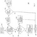
- Figure 5shows a method 160 of identifying patient interface apparatus 112 ( Figures 2 and 4 ), 112' ( Figure 3 ) for use with a particular respiration machine 110 ( Figure 2 ), 110' ( Figure 3 ), 110" ( Figure 4 ) in accordance with an embodiment of the disclosed concept.
- the method 160will be described with reference to the non-limiting embodiment of Figure 2 , although it will be appreciated that the following steps would be substantially similar for other embodiments in accordance with the disclosed concept.
- the patient interface apparatus 112is coupled to the respiration machine 110.
- the detection element (e.g., without limitation, sensor 102 of Figure 2 ) of the respiration machine 110detects if the differentiating feature 106 of patient interface assembly 104 is present, in which case the interface apparatus 112 falls within the predetermined category (e.g., specific brand or make of patient interface apparatus 112). Specifically, if the differentiating feature 106 is detected, then at step 166 the patient interface apparatus 112 is approved for operation with the respiration machine 110 and a determination of whether or not to perform an interface apparatus compensation routine is made. Such a compensation routine is disclosed, for example, and commonly assigned U.S. Patent No. 6,360,741 . If so, at step 168 the respiration machine operating characteristics are synchronized with the patient interface apparatus 112. Finally, at step 170, the respiration machine 110 is operated to deliver the desired therapy to the patient 204 ( Figures 2 and 3 ).
- the predetermined categorye.g., specific brand or make of patient interface apparatus 112
- the method 160includes the optional step 174 of deciding whether or not to perform a manual override of the respiration machine 110, in order to permit it to operate (i.e., at step 170) despite the fact that the patient interface apparatus 112 does not fall within the predetermined category.
- such manual override procedurecould entail the entry of a specific password or code and/or the manual entry of one or more respiration machine operating parameters (e.g., without limitation, ventilation type and duration; manual selection from a list or menu patient interface apparatus). If no such manual override procedure is performed, or alternatively if no such option is available, the method 160 ends at step 176 with the respiration machine 110 being inoperable in conjunction with the unidentified patient interface apparatus (not shown).
- respiration machine operating parameterse.g., without limitation, ventilation type and duration; manual selection from a list or menu patient interface apparatus.
- the example method 160 of Figure 5also includes the option, at step 166, of manually selecting and/or entering patient interface operating parameters (e.g., without limitation, interface apparatus type; therapy type and/or duration), which occurs at step 178 prior to operating (i.e., at step 170) the respiration machine 110, as opposed to having an automatic patient interface apparatus compensation routine conducted, as previously discussed.
- patient interface operating parameterse.g., without limitation, interface apparatus type; therapy type and/or duration
- the disclosed interface apparatus identification system 100( Figure 2 ), 100' ( Figure 3 ), 100" ( Figure 4 ) and method 160 ( Figure 5 ) provide for the relatively quick and easy control of a predetermined category (e.g., without limitation, specific brand or make) of patient interface apparatus (see, for example and without limitation, respiratory mask 112 of Figures 2 and 4 ; see also respiratory mask 112' of Figure 3 ) which can be used in the desired manner with a particular respiration machine (see, for example and without limitation, medical ventilator 110 of Figure 2 ; see also medical ventilators 110' and 110" of Figures 3 and 4 , respectively).
- a predetermined categorye.g., without limitation, specific brand or make
- respiratory mask 112 of Figures 2 and 4see also respiratory mask 112' of Figure 3
- a particular respiration machinesee, for example and without limitation, medical ventilator 110 of Figure 2 ; see also medical ventilators 110' and 110" of Figures 3 and 4 , respectively.
Landscapes
- Health & Medical Sciences (AREA)
- Emergency Medicine (AREA)
- Pulmonology (AREA)
- Engineering & Computer Science (AREA)
- Anesthesiology (AREA)
- Biomedical Technology (AREA)
- Heart & Thoracic Surgery (AREA)
- Hematology (AREA)
- Life Sciences & Earth Sciences (AREA)
- Animal Behavior & Ethology (AREA)
- General Health & Medical Sciences (AREA)
- Public Health (AREA)
- Veterinary Medicine (AREA)
- Measurement Of The Respiration, Hearing Ability, Form, And Blood Characteristics Of Living Organisms (AREA)
Description
- The disclosed concept relates generally to interface apparatus and, more particularly, to an identification system and method for identifying specific patient interface apparatus for use with a respiration machine to deliver a breathable gas to a patient. The disclosed concept also relates to differentiating features for interface apparatus identification systems.
- As shown in
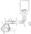
Figure 1 , systems for delivering breathable gas to an airway 2 of a patient 4 to treat a medical disorder typically include a respiration machine 10 (e.g., without limitation, a medical ventilator; a non-invasive ventilator (NIV) such as, for example and without limitation, a CPAP machine), apatient interface apparatus 12 and an air delivery conduit extending therebetween. - In the example of
Figure 1 , the patient interface apparatus is arespiratory mask 12 and theopposing ends 16, 18 of theconduit 14 includeconnectors first connector 20 is structured to connect thefirst end 16 of theconduit 14 to areceptacle 24 of therespiration machine 10, and thesecond connector 22 is structured to connect the second end 18 of theconduit 14 to aseparate swivel 26, which is in turn connected to anelbow 28 of themask 12. - A wide array of mask types, shapes and sizes are available from a variety of different manufacturers and, in general, the aforementioned components (e.g.,
conduit 14; swivel 26) are readily interchangeable such that any of a wide variety of different masks (e.g., 12) can be coupled to therespiration machine 10 for use therewith. For example, theconduit connectors machine receptacle 24,swivel 26 andmask elbow 28 typically have standard dimensions (e.g., without limitation, thereceptacle 24 andswivel 26 typically have an outer diameter (OD) of about 22 mm). However, it is necessary to ensure that themask 12 or other suitable patient interface apparatus (not shown) is compatible with therespiration machine 10. That is, to function properly, themask 12 must be properly identified and characterized by (e.g., synchronized with) therespiration machine 10, for example, to provide the necessary flow compensation in order for the patient 4 to receive the appropriate therapy. There is a desire to control this identification and characterization process, for example, so that only a specific make or brand of patient interface apparatus (e.g., without limitation, mask) will be identified and accepted for use with the respiration machine and in differentiating features therefor. - Accordingly, there is room for improvement in patient interface apparatus identification systems and methods, and in differentiating features therefor.
- These needs and others are met by embodiments of the disclosed concept, which are directed to a patient interface apparatus identification system and method, including a differentiating feature that is incorporated into at least one component of a patient interface assembly and is detectable to identify and distinguish patient interface apparatus that fall within a predetermined category for use with the respiration machine.
EP 1 800 705 A2 discloses an interface apparatus identification system according to the preamble of claim 1. Components of a respiration machine have a remotely-readable identification tag encoded with component identification data. Other types of remote-reading technologies include barcoding, powerless piezo, infrared, optical recognition of color and/or shape, smartcard and EPROM. - As one aspect of the disclosed concept, an interface apparatus identification system for a respiration machine according to claim 1 is provided. The respiration machine is adapted to generate a flow of gas. The interface apparatus identification system comprises: a detection element adapted to communicate with the respiration machine; a patient interface assembly comprising a patient interface apparatus for delivering the flow of gas to an airway of a patient, the patient interface apparatus being selected from a predetermined category; and a differentiating feature incorporated into the patient interface assembly to distinguish patient interface apparatus that fall within the predetermined category from patient interface apparatus that do not fall within the predetermined category. Operation of the respiration machine in conjunction with the patient interface apparatus is dependent upon detection of the differentiating feature by the detection element.
- As another aspect of the disclosed concept, a differentiating feature is provided for an interface apparatus identification system. The interface apparatus identification system includes a detection element adapted to communicate with a respiration machine, and a patient interface assembly comprising a patient interface apparatus for delivering a flow of gas from the respiration machine to an airway of a patient. The patient interface apparatus is selected from a predetermined category. The differentiating feature comprises: a predetermined material property incorporated into at least one component of the patient interface assembly, the material property being exhibited when the at least one component is exposed to a predetermined condition. The predetermined material property is detectable by the detection element of the respiration machine to distinguish patient interface apparatus that fall within the predetermined category from patient interface apparatus that do not fall within the predetermined category, and operation of the respiration machine in conjunction with the patient interface apparatus is dependent upon detection of the predetermined material property.
- As another aspect of the disclosed concept, an interface apparatus identification method according to claim 9 is provided. The method comprises: (a) providing a patient interface assembly, the patient interface assembly comprising: (1) a patient interface apparatus adapted to deliver a flow of gas to an airway of a patient, the patient interface apparatus being selected from a predetermined category, (2) a detection element adapted to communicate with a respiration machine, and (3) a differentiating feature incorporated into the patient interface assembly; (b) coupling the patient interface assembly to the respiration machine; and (c) detecting with the detection element if the differentiating feature of the patient interface assembly is present, thereby falling within the predetermined category, (1) if yes, approving the patient interface apparatus for operation with the respiration machine, (2) if no, prohibiting operation of the respiration machine absent a predetermined user input.
- A full understanding of the disclosed concept can be gained from the following description of the preferred embodiments when read in conjunction with the accompanying drawings in which:
Figure 1 is a partially exploded, partially in section side elevation view of an interface apparatus system;Figure 2 is an exploded, partially in section side elevation view of an interface apparatus identification system and differentiating feature therefor, in accordance with an embodiment of the disclosed concept;Figure 3 is a partially exploded, partially in section side elevation view of an interface identification system and differentiating feature therefor, in accordance with another embodiment of the disclosed concept;Figure 4 is a partially in section side elevation view of an interface identification system and differentiating system therefor, in accordance with another embodiment of the disclosed concept; andFigure 5 is a flow diagram for an interface apparatus identification method, in accordance with an embodiment of the disclosed concept.- For purposes of illustration, embodiments of the disclosed concept will be described as applied to a respiratory mask, although it will become apparent that they could also be applied to identify and differentiate any known or suitable patient interface apparatus adapted for use with a respiration machine.
- As employed herein, the term "patient interface apparatus" refers to any known or suitable mechanism for establishing fluid communication between the respiration machine (e.g., without limitation, a medical ventilator; a non-invasive ventilator (NIV) such as, for example and without limitation, a CPAP machine) and an airway of a patient, and expressly includes, but is not limited to, non-invasive patient interfaces such as masks, nasal canulas, combination nasal/oral masks, and removable mouth pieces, and invasive patient interfaces such as tracheal tubes and endotracheal tubes, as well as humidifiers, nebulizers and meter dose inhalers, which can be invasive or non-invasive.
- As employed herein, the term "detection element" refers to any known or suitable mechanism or sensing element (e.g., without limitation, sensor; photo-eye) for detecting a differentiating feature (e.g., identifying characteristic such as, for example and without limitation, color; florescence; electrical resistance) associated with a predetermined category (e.g., without limitation, make or brand; any known or suitable patient interface assembly or patient interface apparatus operation parameter such as, for example and without limitation, resistance to airflow, exhalation leak rate or any other known or suitable parameter) of patient interface apparatus.
- As employed herein, the terms "fluoresce", "fluorescent" and "fluorescence" refer to the optical characteristic(s) of a particular material or component when it is exposed to a predetermined condition. For example and without limitation, certain polycarbonate materials are designed to fluoresce a specific color when they are exposed to light having a specific wavelength.
- As employed herein, the statement that two or more parts are "coupled" together shall mean that the parts are joined together either directly or joined through one or more intermediate parts.
- As employed herein, the term "number" shall mean one or more than one (i.e., a plurality).
Figure 2 shows an interfaceapparatus identification system 100 for a respiration machine such as, for example and without limitation, a medical ventilator 110 (shown in simplified form). Operation of medical ventilators (e.g., 110) to generate a flow of gas (indicated generally byarrow 200 inFigure 2 ) for delivery to an airway 202 (shown in hidden line drawing inFigure 2 ) of apatient 204, is generally well known. Among other components, theventilator 110 includes acontroller 150, which communicates with aflow generator 152 to generate the aforementioned flow ofgas 200. For ease of illustration and economy of disclosure, theventilator 110 and components (e.g.,sensor 102;controller 150; flow generator 152) are shown in simplified form.- The interface
apparatus identification system 100 includes a detection element 102 (e.g., without limitation, sensor), which is adapted to communicate with thecontroller 150 of theventilator 110, and apatient interface assembly 104, which includes apatient interface apparatus 112 for delivering the flow ofgas 200 from theventilator 110 to theairway 202 of thepatient 204. As will be described in greater detail hereinbelow, thepatient interface apparatus 112 is selected from a predetermined category. A differentiatingfeature 106 is incorporated into at least one component of thepatient interface assembly 104 to distinguishpatient interface apparatus 112 that fall within such predetermined category from those that do not. As will also be described, operation of theventilator 110 in conjunction with thepatient interface apparatus 112, is dependent upon detection of the differentiatingfeature 106 by thedetection element 102. - Accordingly, it will be appreciated that the disclosed concept provides a
system 100 and method 160 (described hereinbelow with respect toFigure 5 ) for relatively quickly and easily controlling which patient interface apparatus are suitably operable with a given respiration machine (e.g., medical ventilator 110). That is, for example and without limitation, the aforementioned predetermined category of patient interface apparatus may be a specific make or brand of patient interface apparatus (e.g., patient interface apparatus that are manufactured and/or sold by a particular company), wherein theventilator 110 will only operate in the desired manner with the specific brand of patient interface apparatus (e.g., 112). It will be appreciated, however, that a "predetermined category" in accordance with the disclosed concept may alternatively, or additionally, be any known or suitable patient interface assembly or patient interface apparatus operation parameter such as, for example and without limitation, resistance to airflow, exhalation leak rate or any other known or suitable parameter. Thus, it will be appreciated that the differentiating feature (e.g., 106) in accordance with the disclosed concept facilitates the identification and distinction of one or more attributes of the patient interface assembly (e.g., 104). - In the example of
Figure 2 , thepatient interface assembly 104 further includes aconduit 114 having first and second opposing ends 116,118. Afirst connector 120 is structured to connect thefirst end 116 of theconduit 114 to acorresponding receptacle 124 ofventilator 110. Asecond connector 122 connects thesecond end 118 ofconduit 114 to therespiratory mask 112. The examplerespiratory mask 112 includes anelbow 128 having anintegral swivel 130. That is, theelbow 128 and integral swivel 130 thereof collectively form a molded extension of therespiratory mask 112, as shown. Accordingly, it will be appreciated that the molded extension 128,130 is connectable directly to thecorresponding connector 122 of theconduit 114, without requiring a separate adapter or swivel element therebetween (see, for example,separate swivel 26 disposed between theconduit 14 andelbow 28 inFigure 1 ). Thus, theswivel 130 is "integral" with theelbow 128 in the respect that theelbow 128 contains the swivel 130, as opposed to there being two separate components that are subsequently joined together. - The
swivel 130 enables pivotal movement of therespiratory mask 112, for example, with respect to thecorresponding conduit connector 122 andconduit 114, without requiring a separate swivel (see, for example,separate swivel 26 ofFigure 1 ) therebetween. Among other benefits, this elbow/swivel assembly 128,130 reduces the number of parts of thepatient interface assembly 104, and reduces the number of connections (e.g., joints) between theventilator 110 andmask 112. This, in turn, advantageously reduces the potential for leaks which can occur at such connections. It will, however, be appreciated that the disclosed interfaceapparatus identification system 100 and method 160 (Figure 5 ) can be employed with any known or suitable alternative type and/or configuration of patient interface apparatus (not shown). - In one non-limiting embodiment of the disclosed concept, the differentiating
feature 106 is a material property, which is exhibited when the component or components of thepatient interface assembly 104 that possess such material property is/are exposed to a predetermined condition. InFigure 2 , for example, the differentiatingfeature 106 is incorporated into themask 112 of thepatient interface assembly 104, and the material property is that the mask fluoresces a predetermined color (see, for example, the fluorescence indicated generally byreference 108 inFigure 2 ) when it is exposed to light having a preselected wavelength. More specifically, themask 112 is made from a material (e.g., without limitation, plastic) that is adapted to change color (e.g., without limitation, fluoresce) when exposed to such light (e.g., without limitation, ultraviolet (UV) light). For example, in one non-limiting embodiment, themask 112 changes from being clear, translucent or generally devoid of color to fluorescing a green color when activated by the specific light. However, it will be appreciated that the material could be formulated to have any known or suitable alternative color change or combination of color changes (e.g., without limitation, shades of color), without departing from the scope of the disclosed concept. It will also be appreciated that the material may be made to activate (e.g., without limitation, fluoresce) only at the a preselected wavelength, or to react differently when exposed to each of a number of different preselected wavelengths. - The detection element (e.g., sensor 102) of the
ventilator 110 is adapted to detect the particular fluorescence and communicate with thecontroller 150 to evaluate whether or not it corresponds to the aforementioned predetermined category ofpatient interface apparatus 112. If so, themask 112 is suitable for operation with theventilator 110. This identification method is further described in greater detail hereinbelow with reference toFigure 5 . - As shown in the non-limiting example embodiment of
Figure 3 , the sensor 102' is disposed proximate to the receptacle 124' of the ventilator 110' and includes aphoto eye 132 for detecting the aforementioned fluorescence 108' (see also fluorescence 108 ofFigure 2 ). InFigure 3 , the ventilator 110' also includes a light 134 (e.g., without limitation, UV light source; light emitting diode (LED); black light), which emits light having the preselected wavelength or other necessary attribute to trigger or activate such fluorescence 108' (see also fluorescence 108 ofFigure 2 ). It will, however, be appreciated that the light 134 or other known or suitable exposure apparatus (not shown) could alternatively be disposed elsewhere (e.g., without limitation, on another component of the interface apparatus identification system 100'; separate from the system 100'). - Continuing to refer to
Figure 3 , it will be appreciated that the differentiating feature 106' may alternatively or additionally be incorporated into another component of the patient interface assembly 104'. For example and without limitation, inFigure 3 , the differentiating feature 106' is incorporated in the first connector 120'. Specifically, when the first connector 120' is attached to the ventilator receptacle 124' and is exposed to the light 134, the first connector 120' fluoresces the aforementioned predetermined color (indicated generally by reference 108' inFigure 3 ), which is detected by the photo-eye 132. In the example ofFigure 3 , the first connector 120' is molded directly into the first end 116' of the conduit 114', as shown, although a separate connector (see, for example,connector 120" ofFigure 4 ) is also within the scope of the disclosed concept. Accordingly, unlike the embodiment ofFigure 2 wherein the differentiatingfeature 106 was employed in therespiratory mask 112, in the example ofFigure 3 , the differentiating feature 106' is instead incorporated into a portion of the conduit 114' and, in particular, as a material property of the first connector 120' thereof. It will, however, be appreciated that the fluorescence 108' (see also fluorescence 108 ofFigure 2 ) and/or any other known or suitable differentiatingfeature 106" (e.g., for example and without limitation, electricallyconductive coating 108" described hereinbelow with respect toFigure 4 ) could be employed in one or more of the components (e.g., without limitation, mask 112'; conduit 114'; connector 120') of the patient interface assembly 104'. - Also in
Figure 3 , as will be discussed in greater detail hereinbelow, it will be appreciated that the outer diameter (OD) 140' of the conduit 114' is smaller than theOD 140 ofconduit 114 in the example ofFigure 2 . For example and without limitation, the OD 140' is about 15 mm, whereas theOD 140 in the example ofFigure 2 is about 20 mm. As will be described, this unique size of the conduit 114' and/or the integral connector 120' therefor, can serve to further differentiate the patient interface assembly 104'. - The example fluorescent material property 108 (
Figure 2 ), 108' (Figure 3 ) will now be described in greater detail. Specifically, certain materials such as, for example and without limitation, specialized polycarbonates change color (e.g., fluoresce) when exposed to a specific light (e.g., UV or black light of a predetermined wavelength). That is, under normal circumstances, in the absence of such exposure, the component has a normal appearance (e.g., transparent; translucent; generally devoid of fluorescence). However, upon exposure to the specific light condition, the component fluoresces a specific color. Suitable polycarbonate materials and color effects therefor are disclosed, for example, inU.S. Patent No. 6,716,368 andWO 2003/102,111 . In accordance with the disclosed concept, this fluorescence is detectable by the aforementioned detecting element (e.g., without limitation,sensor 102 ofFigure 2 ; see also photo-eye 132 ofFigure 3 and photo-eye 132" ofFigure 4 ) and, therefore, is associated with the predetermined category (e.g., without limitation, specific brand or make; or resistance to airflow, exhalation leak rate or any other known or suitable parameter) of patient interface apparatus 112 (Figures 2 and4 ), 112' (Figure 3 ) for the purpose of accepting or rejecting it for operation with the ventilator 110 (Figure 2 ), 110' (Figure 3 ), 110" (Figure 4 ). It will, therefore, be appreciated that one or more of the components (e.g., without limitation,mask 112;conduit 114; connectors 120,122) could be made to exhibit a specific fluorescence 108 (Figure 2 ), 108' (Figure 3 ) or color change that is unique to these specific brand or make of mask 112 (Figures 2 and4 ), 112' (Figure 3 ) or other suitable patient interface apparatus (not shown), as defined herein. Thus, the ventilator 110 (Figure 2 ), 110' (Figure 3 ), 110" (Figure 4 ) can be rendered inoperable with any other brand or make of patient interface apparatus (not shown), or with a patient interface apparatus having or not having any other known or suitable parameter falling within a predetermined category, as desired. Figure 4 shows another non-limiting alternative embodiment in accordance with the disclosed concept, wherein themask 112 is connectable directly to aconnector 120", which in turn is connectable directly to thereceptacle 124" of theventilator 110". Theidentification system 100" ofFigure 4 also illustrates analternative differentiating feature 106", which can be employed instead of or in addition to the aforementioned fluorescence 108 (Figure 2 ), 108' (Figure 3 ). Specifically, thesingle connector 120" preferably includes an electrically conductive coating (indicated generally byreference 108" inFigure 4 ), which has a predetermined electrical resistance that is detectable by thedetection element 102" (e.g., without limitation,electrical conductor 132"). Other components of thepatient interface assembly 104" may also include an electrically conductive coating for suitable detection by thedetection element 102" and electrical communication with theconductor 132", as desired. In the example ofFigure 4 , the elbow/swivel assembly 128,130 includes an electrically conductive coating (indicated generally byreference 109 inFigure 4 ), which has substantially the same electrical resistance as coating 108" and, therefore, is electrically connectable therewith. Alternatively, the elbow/swivel assembly 128,130 and, in particular, the electricallyconductive coating 109 thereof, could be directly connected to theventilator receptacle 124" (such direct connection is not shown) for detection by theelectrical conductor 132" of the connecteddetection element 102".- It will be appreciated that the
fluorescence 108 differentiatingfeature 106 described with respect to themask 112 with reference toFigure 2 could be used in the embodiment ofFigure 4 , without the aforementioned electricallyconductive coating 108". That is, themask 112 could be structured to fluoresce through theconnector 120" ofFigure 4 to be detected by a photo-eye 132". - In addition to the foregoing, it will be appreciated that the various components of the patient interface assembly 104 (
Figure 2 ), 104' (Figure 3 ), 104" (Figure 4 ) may have a variety of specific sizes and structures to further distinguish and differentiate the predetermined category (e.g., without limitation, specific make or brand; any known or suitable patient interface assembly or patient interface apparatus operation parameter such as, for example and without limitation, resistance to airflow, exhalation leak rate or any other known or suitable parameter) of patient interface apparatus 112 (Figures 2 and4 ), 112' (Figure 3 ) from others. For example, inFigure 2 theventilator receptacle 124 has an outer diameter (OD) 134 and an inner diameter (ID) 136, which in accordance with one non-limiting embodiment are about 22 mm and about 19 mm, respectively, and the end of the mask elbow; 128 tapers to an outer diameter (OD) 138, which is also about 19 mm. Thus, it will be appreciated that themask 112 can be employed with aconduit 114 having an outer diameter (OD) 140 of about 22 mm, which is a generally standard conduit dimension in the art. More specifically, theOD 138 of theunique mask elbow 128 permits it to be inserted into thesecond connector 122 of theconduit 114, for a direct connection thereto, or alternatively to be inserted directly into theID 136 of theventilator receptacle 124. Similarly, theOD 134 of theventilator receptacle 124 is sized and configured to be inserted into thefirst connector 120 of theconduit 114 for direct connection thereto. It will, however, be appreciated that one or more of the components of thepatient interface assembly 104 could be made to have a suitable alternative dimension and/or configuration, without departing from the scope of the disclosed concept. - For example and without limitation, in the non-limiting example embodiment of
Figure 3 , the ventilator receptacle 124' has the same OD 134' as in the example embodiment ofFigure 2 , previously discussed, and the end of the mask elbow 128' has the same OD 138', but the conduit 114' is configured differently. Specifically, the OD 140' of the conduit 114' is smaller than theOD 140 ofconduit 114 ofFigure 2 . For example and without limitation, in one non-limiting embodiment, the OD 140' is about 15 mm. This unique conduit dimension (e.g., without limitation, OD 140') necessitates a unique connector 120' to facilitate connection of the first end 116' of the conduit 114' to the ventilator receptacle 124'. A portion of the ventilator receptacle 124' and the connector 120' are shown in section view inFigure 3 to illustrate this structural relationship. In the example ofFigure 3 , the connector 120' is a molded extension of the conduit 114', although it will be appreciated that it could alternatively be a separate connector (see, for example,separate connector 120" ofFigure 4 ). The second connector 122', which is attached to the second end 118' of the conduit 114' is substantially similar in size tosecond connector 122 in the example ofFigure 2 . Accordingly, it will be appreciated that the conduit 114', connector 120' therefor, and the reduced OD 138' of the mask elbow 128' are unique in size and configuration and, therefore, are only suitable for use with the predetermined category (e.g., without limitation, specific brand or make) of mask 112'. Figure 5 shows amethod 160 of identifying patient interface apparatus 112 (Figures 2 and4 ), 112' (Figure 3 ) for use with a particular respiration machine 110 (Figure 2 ), 110' (Figure 3 ), 110" (Figure 4 ) in accordance with an embodiment of the disclosed concept. For economy of disclosure, themethod 160 will be described with reference to the non-limiting embodiment ofFigure 2 , although it will be appreciated that the following steps would be substantially similar for other embodiments in accordance with the disclosed concept. Specifically, at afirst step 162, thepatient interface apparatus 112 is coupled to therespiration machine 110. Atstep 164, the detection element (e.g., without limitation,sensor 102 ofFigure 2 ) of therespiration machine 110 detects if the differentiatingfeature 106 ofpatient interface assembly 104 is present, in which case theinterface apparatus 112 falls within the predetermined category (e.g., specific brand or make of patient interface apparatus 112). Specifically, if the differentiatingfeature 106 is detected, then atstep 166 thepatient interface apparatus 112 is approved for operation with therespiration machine 110 and a determination of whether or not to perform an interface apparatus compensation routine is made. Such a compensation routine is disclosed, for example, and commonly assignedU.S. Patent No. 6,360,741 . If so, atstep 168 the respiration machine operating characteristics are synchronized with thepatient interface apparatus 112. Finally, atstep 170, therespiration machine 110 is operated to deliver the desired therapy to the patient 204 (Figures 2 and3 ).- Returning to step 164, if no detection of the differentiating
feature 106 of thepatient interface assembly 104 is detected by thedetection element 102, then thepatient interface apparatus 112 does not fall within the predetermined category such that it is not recognized, as indicated atstep 172. In the example ofFigure 5 , themethod 160 includes theoptional step 174 of deciding whether or not to perform a manual override of therespiration machine 110, in order to permit it to operate (i.e., at step 170) despite the fact that thepatient interface apparatus 112 does not fall within the predetermined category. For example and without limitation, such manual override procedure could entail the entry of a specific password or code and/or the manual entry of one or more respiration machine operating parameters (e.g., without limitation, ventilation type and duration; manual selection from a list or menu patient interface apparatus). If no such manual override procedure is performed, or alternatively if no such option is available, themethod 160 ends atstep 176 with therespiration machine 110 being inoperable in conjunction with the unidentified patient interface apparatus (not shown). - The
example method 160 ofFigure 5 also includes the option, atstep 166, of manually selecting and/or entering patient interface operating parameters (e.g., without limitation, interface apparatus type; therapy type and/or duration), which occurs atstep 178 prior to operating (i.e., at step 170) therespiration machine 110, as opposed to having an automatic patient interface apparatus compensation routine conducted, as previously discussed. - Accordingly, the disclosed interface apparatus identification system 100 (
Figure 2 ), 100' (Figure 3 ), 100" (Figure 4 ) and method 160 (Figure 5 ) provide for the relatively quick and easy control of a predetermined category (e.g., without limitation, specific brand or make) of patient interface apparatus (see, for example and without limitation,respiratory mask 112 ofFigures 2 and4 ; see also respiratory mask 112' ofFigure 3 ) which can be used in the desired manner with a particular respiration machine (see, for example and without limitation,medical ventilator 110 ofFigure 2 ; see alsomedical ventilators 110' and 110" ofFigures 3 and4 , respectively). - While specific embodiments of the disclosed concept have been described in detail, it will be appreciated by those skilled in the art that various modifications and alternatives to those details could be developed in light of the overall teachings of the disclosure. Accordingly, the particular arrangements disclosed are meant to be illustrative only and not limiting as to the scope of the disclosed concept which is to be given the full breadth of the claims appended and any and all equivalents thereof.
Claims (15)
- An interface apparatus identification system (100, 100', 100") for a respiration machine (110, 110', 110"), the respiration machine being adapted to generate a flow of gas, the interface apparatus identification system comprising:a patient interface assembly (104, 104', 104") comprising:a patient interface apparatus (112, 112') for delivering the flow of gas to an airway (202) of a patient (204), the patient interface apparatus being selected from a predetermined category; anda differentiating feature (106, 106', 106") incorporated into the patient interface assembly to distinguish patient interface apparatus that fall within said predetermined category from patient interface apparatus that do not fall within said predetermined category; anda detection element (102, 102') adapted to detect the differentiating feature (106,106',106") and to communicate with the respiration machine;characterized in thatthe differentiating feature is a material property (108, 108', 108"), wherein at least one component (128, 120', 120") of the patient interface assembly possesses the material property; and wherein the material property is a change of color of the at least one component when the at least one component is exposed to light having a preselected wavelength or preselected wavelengths.
- The interface apparatus identification system (100, 100', 100") of claim 1 wherein the predetermined category of patient interface apparatus (112, 112') is a specific brand of patient interface apparatus.
- The interface apparatus identification system (100') of claim 1, further comprising the respiration machine, which includes a receptacle (124'); wherein the detection element (102') is a sensor disposed proximate to the receptacle; wherein the patient interface apparatus (112') is a respiratory mask; wherein the patient interface assembly further comprises at least one connector (120') structured to couple the respiratory mask to the receptacle; and wherein, when the at least one connector and the respiratory mask are coupled to the receptacle, the differentiating feature (108') is detectable by the sensor, wherein operation of the respiration machine in conjunction with the patient interface apparatus is dependent upon detection of the differentiating feature.
- The interface apparatus identification system (100') of claim 3 wherein the patient interface assembly (104') further comprises a conduit (114'); wherein the conduit includes a first end (116'), a second end (118') disposed opposite and distal from the first end, and a predetermined diameter; and wherein the at least one connector is a first connector (120') structured to connect the first end of the conduit to the receptacle (124') of the respiration machine (110') and a second connector (122') connecting the second end of the conduit to the respiratory mask (112').
- The interface apparatus identification system (100') of claim 4 wherein the first connector is molded directly into the first end of the conduit.
- The interface apparatus identification system (100') of claim 3 wherein the respiratory mask (112') includes an elbow (128') with an integral swivel (130'); wherein the elbow and the integral swivel comprise a molded extension of the respiratory mask; and wherein the molded extension is connectable directly to a corresponding one of the at least one connector to enable pivotal movement of the respiratory mask with respect to the at least one connector without requiring a separate swivel therebetween.
- The interface apparatus identification system (100, 100', 100") of claim 1 wherein the material property is a fluorescence of a predetermined color triggered by exposure to said light; and wherein the detection element of the respiration machine comprises a photo eye (132', 132") adapted to detect said fluorescence.
- The interface apparatus identification system (100, 100', 100") of claim 1 wherein the at least one component includes an electrically conductive coating; wherein the electrically conductive coating has a predetermined resistance; and wherein the detection element of the respiration machine is adapted to detect said predetermined resistance.
- An interface apparatus identification method (150) comprising:(a) providing a patient interface assembly (104, 104', 104") and the interface apparatus identification system (100, 100', 100") according to any one of claims 1-8;(b) coupling the patient interface assembly to the respiration machine (110, 110', 110"); and(c) detecting with the detection element (102, 102') if the differentiating feature (106, 106', 106") of the patient interface assembly is present, thereby falling within the predetermined category,(1) if yes, approving the patient interface apparatus for operation with the respiration machine,(2) if no, prohibiting operation of the respiration machine absent a predetermined user input.
- The method of claim 9, further comprising:(a) the detection element comprising a sensor disposed proximate to a receptacle (124', 124") of the respiration machine,(b) the patient interface apparatus (112') comprising a respiratory mask,(c) coupling the respiratory mask to the receptacle of the respiratory machine with at least one connector (120'), and(d) responsive to the respiratory mask and the at least one connector being coupled to the receptacle, detecting with the sensor the presence or absence of the differentiating feature.
- The method of claim 10, further comprising:(a) the at least one connector comprising a single connector,(b) connecting one end of the single connector directly to the receptacle of the respiration machine, and(c) connecting the respiratory mask directly to the other end of the single connector.
- The method of claim 10, further comprising:(a) providing the patient interface assembly with a conduit (114, 114'),(b) providing as the at least one connector a first connector (120, 120') and a second connector (122, 122'),(c) connecting a first end (116, 116') of the conduit to the receptacle of the respiration machine with the first connector, and(d) connecting the second end (118, 118') of the conduit to the respiratory mask with the second connector.
- The method of claim 9, further comprising:(a) exposing the at least one component to light having a preselected wavelength or preselected wavelengths, and(b) responsive to said exposure, detecting with a photo eye (132', 132") the presence or absence of a fluorescence of a predetermined color.
- The method of claim 9, further comprising:(a) responsive to the differentiating featuring being detected, performing a patient interface apparatus compensation routine,(b) responsive to the compensation routine, synchronizing a number of operating characteristics of the respiration machine with the patient interface apparatus, and(c) operating the respiration machine in conjunction with the patient interface apparatus.
- The method of claim 9, further comprising:(a) responsive to the differentiating featuring not being detected, performing as said predetermined user input, a manual override of the respiration machine,(b) manually selecting a number of operating characteristics of the respiration machine, and(c) operating the respiration machine based upon said manually selected operating characteristics.
Applications Claiming Priority (2)
| Application Number | Priority Date | Filing Date | Title |
|---|---|---|---|
| US12276508P | 2008-12-16 | 2008-12-16 | |
| PCT/IB2009/055253WO2010070494A1 (en) | 2008-12-16 | 2009-11-21 | Interface apparatus identification system and method and differentiating feature therefor |
Publications (2)
| Publication Number | Publication Date |
|---|---|
| EP2379151A1 EP2379151A1 (en) | 2011-10-26 |
| EP2379151B1true EP2379151B1 (en) | 2017-09-13 |
Family
ID=41510779
Family Applications (1)
| Application Number | Title | Priority Date | Filing Date |
|---|---|---|---|
| EP09771784.7ANot-in-forceEP2379151B1 (en) | 2008-12-16 | 2009-11-21 | Interface apparatus identification system and method |
Country Status (6)
| Country | Link |
|---|---|
| US (1) | US8997736B2 (en) |
| EP (1) | EP2379151B1 (en) |
| JP (1) | JP5486016B2 (en) |
| CN (1) | CN102245252A (en) |
| BR (1) | BRPI0917758A2 (en) |
| WO (1) | WO2010070494A1 (en) |
Families Citing this family (28)
| Publication number | Priority date | Publication date | Assignee | Title |
|---|---|---|---|---|
| AU2003903139A0 (en) | 2003-06-20 | 2003-07-03 | Resmed Limited | Breathable gas apparatus with humidifier |
| NZ700746A (en) | 2005-10-14 | 2015-09-25 | Resmed Ltd | Flow generator message system |
| US8695602B2 (en) | 2011-05-11 | 2014-04-15 | Carefusion 207, Inc. | Corrugated flexible seal of a ventilation mask |
| US8915250B2 (en) | 2011-05-11 | 2014-12-23 | Carefusion 207, Inc. | Tube placement in non-invasive ventilation |
| US9022029B2 (en) | 2011-05-11 | 2015-05-05 | Carefusion 207, Inc. | Carbon-dioxide sampling system for accurately monitoring carbon dioxide in exhaled breath |
| US8905028B2 (en) | 2011-05-11 | 2014-12-09 | Carefusion 207, Inc. | Non-invasive ventilation facial skin protection |
| US10195379B2 (en) | 2012-03-06 | 2019-02-05 | Koninklijke Philips N.V. | Patient interface having illuminated portion |
| CN118304537A (en) | 2012-05-18 | 2024-07-09 | 瑞思迈私人有限公司 | Nasal mask system |
| JP6266647B2 (en)* | 2012-12-17 | 2018-01-24 | コーニンクレッカ フィリップス エヌ ヴェKoninklijke Philips N.V. | Multifunctional docking module for pressure support therapy system |
| US10091301B2 (en) | 2013-06-27 | 2018-10-02 | Koninklijke Philips N.V. | Automatic external sensor interface |
| US9795757B2 (en)* | 2013-06-28 | 2017-10-24 | Vyaire Medical Capital Llc | Fluid inlet adapter |
| US10532174B2 (en)* | 2014-02-21 | 2020-01-14 | Masimo Corporation | Assistive capnography device |
| CN104001247A (en)* | 2014-06-18 | 2014-08-27 | 宁波圣宇瑞医疗器械有限公司 | Atomizer and atomizing device |
| EP3262549A1 (en)* | 2015-02-25 | 2018-01-03 | Koninklijke Philips N.V. | System for pneumatic testing of gas flow module and method of operation thereof |
| US10245406B2 (en) | 2015-03-24 | 2019-04-02 | Ventec Life Systems, Inc. | Ventilator with integrated oxygen production |
| US11247015B2 (en) | 2015-03-24 | 2022-02-15 | Ventec Life Systems, Inc. | Ventilator with integrated oxygen production |
| CN108025154B (en)* | 2015-07-20 | 2021-03-23 | 费雪派克医疗保健有限公司 | Exhalation port |
| US10773049B2 (en) | 2016-06-21 | 2020-09-15 | Ventec Life Systems, Inc. | Cough-assist systems with humidifier bypass |
| US11318269B2 (en) | 2016-11-07 | 2022-05-03 | ResMed Pty Ltd | Conduit for respiratory therapy apparatus |
| WO2018154060A1 (en)* | 2017-02-23 | 2018-08-30 | Koninklijke Philips N.V. | Method for detecting circuit disconnect in a patient care system |
| CN107961428A (en)* | 2017-12-16 | 2018-04-27 | 湖南明康中锦医疗科技发展有限公司 | Breathe humidification instrument patient interface identifying system and method |
| WO2019221852A1 (en) | 2018-05-13 | 2019-11-21 | Ahmad Samir Saleh | Portable medical ventilator system using portable oxygen concentrators |
| KR20220095235A (en)* | 2019-11-11 | 2022-07-06 | 레스트풀 로보틱스, 인크. | automatic placement of masks |
| WO2021202213A2 (en) | 2020-03-30 | 2021-10-07 | Zoll Medical Corporation | Medical device system and hardware for sensor data acquisition |
| CN111905226B (en)* | 2020-09-16 | 2025-04-22 | 合肥九研医药科技开发有限公司 | A respiratory maintenance system providing humidified oxygen therapy |
| US20220176004A1 (en)* | 2020-12-07 | 2022-06-09 | The Ritedose Corporation | Nebulizer disinfecting system and method of use |
| US11931517B2 (en)* | 2022-03-16 | 2024-03-19 | Herman David Palmieri | Germicidal UV light device |
| EP4471795A1 (en) | 2023-06-02 | 2024-12-04 | Koninklijke Philips N.V. | System and method for generating predictive indicator of a difference between pap titration and conventional sleep sessions |
Citations (1)
| Publication number | Priority date | Publication date | Assignee | Title |
|---|---|---|---|---|
| EP1800705A2 (en)* | 2005-12-21 | 2007-06-27 | ResMed Limited | Identification system and method for mask and ventilator components |
Family Cites Families (21)
| Publication number | Priority date | Publication date | Assignee | Title |
|---|---|---|---|---|
| JPS61359A (en)* | 1984-06-14 | 1986-01-06 | 株式会社東芝 | Respiration monitor apparatus |
| JPS6324945A (en)* | 1986-07-17 | 1988-02-02 | 川重防災工業株式会社 | Medical gas discrimination apparatus |
| JPH0737448A (en)* | 1993-07-19 | 1995-02-07 | Sumitomo Wiring Syst Ltd | Inspection board of wire harness and appearance inspection on the board |
| JP2756086B2 (en)* | 1994-08-05 | 1998-05-25 | サーパス工業株式会社 | Pipe fittings |
| US5714121A (en)* | 1995-09-28 | 1998-02-03 | Optical Sensors Incorporated | Optical carbon dioxide sensor, and associated methods of manufacture |
| US6126610A (en)* | 1997-11-03 | 2000-10-03 | Novametrix Medical Systems, Inc. | Pneumatic connector with encoding |
| US6360741B2 (en)* | 1998-11-25 | 2002-03-26 | Respironics, Inc. | Pressure support system with a low leak alarm and method of using same |
| US7043979B2 (en)* | 2001-01-31 | 2006-05-16 | Fisher & Paykel Healthcare Limited | Respiratory humidification system |
| US6716368B1 (en)* | 2001-08-06 | 2004-04-06 | General Electric Company | Phosporescent polycarbonate and molded articles |
| US6692659B2 (en) | 2002-05-31 | 2004-02-17 | General Electric Company | Phosporescent polycarbonate, concentrate and molded articles |
| CA2596259C (en)* | 2005-02-01 | 2013-08-20 | Baxter International Inc. | Infusion delivery system |
| AU2006220222A1 (en)* | 2005-03-01 | 2006-09-08 | Resmed Limited | Recognition system for an apparatus that delivers breathable gas to a patient |
| US8496001B2 (en)* | 2005-06-08 | 2013-07-30 | Dräger Medical GmbH | Process and device for the automatic identification of breathing tubes |
| DE102005045720B3 (en)* | 2005-09-24 | 2007-01-04 | Dräger Medical AG & Co. KG | Method for operating breathing systems, e.g. anaesthesia units, involves using a wireless read-out unit to select system operating data from a respiratory flow sensor after comparison with corresponding stored data |
| JP2007117568A (en)* | 2005-10-31 | 2007-05-17 | Osada Res Inst Ltd | Dental treatment unit |
| US20080053446A1 (en)* | 2006-03-31 | 2008-03-06 | Tiara Medical Systems, Inc. | Adjustable cpap mask assembly |
| US20070272240A1 (en)* | 2006-05-04 | 2007-11-29 | Acoba, Llc. | Hose system for bilateral positive airway pressure device |
| US9056179B2 (en)* | 2006-05-31 | 2015-06-16 | Acoba, L.L.C. | Hose connection system for narially sensitive diagnostic devices |
| DE102006053857B3 (en)* | 2006-11-14 | 2007-08-16 | Dräger Medical AG & Co. KG | Respiratory tubing connection device for connecting respiratory tubing to a respiratory device has a main body, an enveloping body, a respiratory gas through-channel and link to a respiratory device |
| EP2088983B1 (en)* | 2006-11-22 | 2018-01-24 | Planmeca Oy | Console for devices and dental care unit |
| DE102007029016B3 (en)* | 2007-06-23 | 2008-06-05 | Dräger Medical AG & Co. KG | Accessory device for e.g. respirator, has communication unit attached for wireless communication with another unit, and mechanical interface with mechanical coding, whose information content is stored in another communication unit |
- 2009
- 2009-11-21USUS13/131,630patent/US8997736B2/ennot_activeExpired - Fee Related
- 2009-11-21JPJP2011540273Apatent/JP5486016B2/ennot_activeExpired - Fee Related
- 2009-11-21BRBRPI0917758Apatent/BRPI0917758A2/ennot_activeIP Right Cessation
- 2009-11-21CNCN2009801503787Apatent/CN102245252A/enactivePending
- 2009-11-21EPEP09771784.7Apatent/EP2379151B1/ennot_activeNot-in-force
- 2009-11-21WOPCT/IB2009/055253patent/WO2010070494A1/enactiveApplication Filing
Patent Citations (1)
| Publication number | Priority date | Publication date | Assignee | Title |
|---|---|---|---|---|
| EP1800705A2 (en)* | 2005-12-21 | 2007-06-27 | ResMed Limited | Identification system and method for mask and ventilator components |
Also Published As
| Publication number | Publication date |
|---|---|
| US20110232645A1 (en) | 2011-09-29 |
| EP2379151A1 (en) | 2011-10-26 |
| WO2010070494A1 (en) | 2010-06-24 |
| BRPI0917758A2 (en) | 2016-02-23 |
| CN102245252A (en) | 2011-11-16 |
| US8997736B2 (en) | 2015-04-07 |
| JP2012511949A (en) | 2012-05-31 |
| JP5486016B2 (en) | 2014-05-07 |
Similar Documents
| Publication | Publication Date | Title |
|---|---|---|
| EP2379151B1 (en) | Interface apparatus identification system and method | |
| US10279134B2 (en) | Recognition system for an apparatus that delivers breathable gas to a patient | |
| US20230321376A1 (en) | Breathing assistance apparatus with serviceability features | |
| US9056179B2 (en) | Hose connection system for narially sensitive diagnostic devices | |
| EP2640451B1 (en) | Methods and devices in the field of treatment with medical gases | |
| CN103842013B (en) | Snorkel system | |
| US11819621B2 (en) | Apparatus for connecting oxygen delivery control instrument to patient delivery device | |
| US8766790B2 (en) | Wireless identification of a component of a pressure support system | |
| EP3229885B1 (en) | Systems and methods for heating and humidifying inspired gases during mechanical ventilation | |
| EP3088031A1 (en) | Humidification apparatus with rfid tag sensor | |
| US20070272240A1 (en) | Hose system for bilateral positive airway pressure device | |
| JP2007175496A (en) | Mask and ventilator component identification system and method | |
| CN110049796A (en) | Aerosol delivery system | |
| JP2008513059A (en) | Gastric tube placement indicator | |
| CN114938635A (en) | Connectors for patient ventilation systems | |
| JP4912462B2 (en) | Artificial respiration assembly with carbon dioxide detector | |
| WO1995026212A1 (en) | A method and an apparatus for training a patient to use an inhaler | |
| US20220134030A1 (en) | Pathogen sensing adaptors for use in breathing circuits | |
| AU2013206410B2 (en) | Humidification apparatus having rfid tag sensor at patient end of gas pathway | |
| NZ733636B2 (en) | Systems and methods for heating and humidifying inspired gases during mechanical ventilation | |
| NZ765654B2 (en) | Flow Generator Message System | |
| NZ765654A (en) | Flow Generator Message System |
Legal Events
| Date | Code | Title | Description |
|---|---|---|---|
| PUAI | Public reference made under article 153(3) epc to a published international application that has entered the european phase | Free format text:ORIGINAL CODE: 0009012 | |
| 17P | Request for examination filed | Effective date:20110718 | |
| AK | Designated contracting states | Kind code of ref document:A1 Designated state(s):AT BE BG CH CY CZ DE DK EE ES FI FR GB GR HR HU IE IS IT LI LT LU LV MC MK MT NL NO PL PT RO SE SI SK SM TR | |
| DAX | Request for extension of the european patent (deleted) | ||
| RAP1 | Party data changed (applicant data changed or rights of an application transferred) | Owner name:KONINKLIJKE PHILIPS N.V. | |
| 17Q | First examination report despatched | Effective date:20160205 | |
| GRAP | Despatch of communication of intention to grant a patent | Free format text:ORIGINAL CODE: EPIDOSNIGR1 | |
| INTG | Intention to grant announced | Effective date:20170411 | |
| GRAS | Grant fee paid | Free format text:ORIGINAL CODE: EPIDOSNIGR3 | |
| GRAA | (expected) grant | Free format text:ORIGINAL CODE: 0009210 | |
| AK | Designated contracting states | Kind code of ref document:B1 Designated state(s):AT BE BG CH CY CZ DE DK EE ES FI FR GB GR HR HU IE IS IT LI LT LU LV MC MK MT NL NO PL PT RO SE SI SK SM TR | |
| REG | Reference to a national code | Ref country code:GB Ref legal event code:FG4D | |
| REG | Reference to a national code | Ref country code:CH Ref legal event code:EP | |
| REG | Reference to a national code | Ref country code:IE Ref legal event code:FG4D | |
| REG | Reference to a national code | Ref country code:AT Ref legal event code:REF Ref document number:927551 Country of ref document:AT Kind code of ref document:T Effective date:20171015 | |
| REG | Reference to a national code | Ref country code:DE Ref legal event code:R096 Ref document number:602009048343 Country of ref document:DE | |
| REG | Reference to a national code | Ref country code:FR Ref legal event code:PLFP Year of fee payment:9 | |
| REG | Reference to a national code | Ref country code:NL Ref legal event code:MP Effective date:20170913 | |
| REG | Reference to a national code | Ref country code:LT Ref legal event code:MG4D | |
| PG25 | Lapsed in a contracting state [announced via postgrant information from national office to epo] | Ref country code:LT Free format text:LAPSE BECAUSE OF FAILURE TO SUBMIT A TRANSLATION OF THE DESCRIPTION OR TO PAY THE FEE WITHIN THE PRESCRIBED TIME-LIMIT Effective date:20170913 Ref country code:NO Free format text:LAPSE BECAUSE OF FAILURE TO SUBMIT A TRANSLATION OF THE DESCRIPTION OR TO PAY THE FEE WITHIN THE PRESCRIBED TIME-LIMIT Effective date:20171213 Ref country code:SE Free format text:LAPSE BECAUSE OF FAILURE TO SUBMIT A TRANSLATION OF THE DESCRIPTION OR TO PAY THE FEE WITHIN THE PRESCRIBED TIME-LIMIT Effective date:20170913 Ref country code:FI Free format text:LAPSE BECAUSE OF FAILURE TO SUBMIT A TRANSLATION OF THE DESCRIPTION OR TO PAY THE FEE WITHIN THE PRESCRIBED TIME-LIMIT Effective date:20170913 Ref country code:HR Free format text:LAPSE BECAUSE OF FAILURE TO SUBMIT A TRANSLATION OF THE DESCRIPTION OR TO PAY THE FEE WITHIN THE PRESCRIBED TIME-LIMIT Effective date:20170913 | |
| REG | Reference to a national code | Ref country code:AT Ref legal event code:MK05 Ref document number:927551 Country of ref document:AT Kind code of ref document:T Effective date:20170913 | |
| PG25 | Lapsed in a contracting state [announced via postgrant information from national office to epo] | Ref country code:LV Free format text:LAPSE BECAUSE OF FAILURE TO SUBMIT A TRANSLATION OF THE DESCRIPTION OR TO PAY THE FEE WITHIN THE PRESCRIBED TIME-LIMIT Effective date:20170913 Ref country code:BG Free format text:LAPSE BECAUSE OF FAILURE TO SUBMIT A TRANSLATION OF THE DESCRIPTION OR TO PAY THE FEE WITHIN THE PRESCRIBED TIME-LIMIT Effective date:20171213 Ref country code:GR Free format text:LAPSE BECAUSE OF FAILURE TO SUBMIT A TRANSLATION OF THE DESCRIPTION OR TO PAY THE FEE WITHIN THE PRESCRIBED TIME-LIMIT Effective date:20171214 Ref country code:ES Free format text:LAPSE BECAUSE OF FAILURE TO SUBMIT A TRANSLATION OF THE DESCRIPTION OR TO PAY THE FEE WITHIN THE PRESCRIBED TIME-LIMIT Effective date:20170913 | |
| PG25 | Lapsed in a contracting state [announced via postgrant information from national office to epo] | Ref country code:NL Free format text:LAPSE BECAUSE OF FAILURE TO SUBMIT A TRANSLATION OF THE DESCRIPTION OR TO PAY THE FEE WITHIN THE PRESCRIBED TIME-LIMIT Effective date:20170913 | |
| PG25 | Lapsed in a contracting state [announced via postgrant information from national office to epo] | Ref country code:CZ Free format text:LAPSE BECAUSE OF FAILURE TO SUBMIT A TRANSLATION OF THE DESCRIPTION OR TO PAY THE FEE WITHIN THE PRESCRIBED TIME-LIMIT Effective date:20170913 Ref country code:RO Free format text:LAPSE BECAUSE OF FAILURE TO SUBMIT A TRANSLATION OF THE DESCRIPTION OR TO PAY THE FEE WITHIN THE PRESCRIBED TIME-LIMIT Effective date:20170913 Ref country code:PL Free format text:LAPSE BECAUSE OF FAILURE TO SUBMIT A TRANSLATION OF THE DESCRIPTION OR TO PAY THE FEE WITHIN THE PRESCRIBED TIME-LIMIT Effective date:20170913 | |
| PG25 | Lapsed in a contracting state [announced via postgrant information from national office to epo] | Ref country code:IT Free format text:LAPSE BECAUSE OF FAILURE TO SUBMIT A TRANSLATION OF THE DESCRIPTION OR TO PAY THE FEE WITHIN THE PRESCRIBED TIME-LIMIT Effective date:20170913 Ref country code:AT Free format text:LAPSE BECAUSE OF FAILURE TO SUBMIT A TRANSLATION OF THE DESCRIPTION OR TO PAY THE FEE WITHIN THE PRESCRIBED TIME-LIMIT Effective date:20170913 Ref country code:SK Free format text:LAPSE BECAUSE OF FAILURE TO SUBMIT A TRANSLATION OF THE DESCRIPTION OR TO PAY THE FEE WITHIN THE PRESCRIBED TIME-LIMIT Effective date:20170913 Ref country code:SM Free format text:LAPSE BECAUSE OF FAILURE TO SUBMIT A TRANSLATION OF THE DESCRIPTION OR TO PAY THE FEE WITHIN THE PRESCRIBED TIME-LIMIT Effective date:20170913 Ref country code:EE Free format text:LAPSE BECAUSE OF FAILURE TO SUBMIT A TRANSLATION OF THE DESCRIPTION OR TO PAY THE FEE WITHIN THE PRESCRIBED TIME-LIMIT Effective date:20170913 Ref country code:IS Free format text:LAPSE BECAUSE OF FAILURE TO SUBMIT A TRANSLATION OF THE DESCRIPTION OR TO PAY THE FEE WITHIN THE PRESCRIBED TIME-LIMIT Effective date:20180113 | |
| REG | Reference to a national code | Ref country code:DE Ref legal event code:R097 Ref document number:602009048343 Country of ref document:DE | |
| PG25 | Lapsed in a contracting state [announced via postgrant information from national office to epo] | Ref country code:MC Free format text:LAPSE BECAUSE OF FAILURE TO SUBMIT A TRANSLATION OF THE DESCRIPTION OR TO PAY THE FEE WITHIN THE PRESCRIBED TIME-LIMIT Effective date:20170913 | |
| PLBE | No opposition filed within time limit | Free format text:ORIGINAL CODE: 0009261 | |
| STAA | Information on the status of an ep patent application or granted ep patent | Free format text:STATUS: NO OPPOSITION FILED WITHIN TIME LIMIT | |
| PG25 | Lapsed in a contracting state [announced via postgrant information from national office to epo] | Ref country code:CH Free format text:LAPSE BECAUSE OF NON-PAYMENT OF DUE FEES Effective date:20171130 Ref country code:DK Free format text:LAPSE BECAUSE OF FAILURE TO SUBMIT A TRANSLATION OF THE DESCRIPTION OR TO PAY THE FEE WITHIN THE PRESCRIBED TIME-LIMIT Effective date:20170913 Ref country code:LI Free format text:LAPSE BECAUSE OF NON-PAYMENT OF DUE FEES Effective date:20171130 | |
| 26N | No opposition filed | Effective date:20180614 | |
| GBPC | Gb: european patent ceased through non-payment of renewal fee | Effective date:20171213 | |
| PG25 | Lapsed in a contracting state [announced via postgrant information from national office to epo] | Ref country code:LU Free format text:LAPSE BECAUSE OF NON-PAYMENT OF DUE FEES Effective date:20171121 | |
| REG | Reference to a national code | Ref country code:BE Ref legal event code:MM Effective date:20171130 | |
| REG | Reference to a national code | Ref country code:IE Ref legal event code:MM4A | |
| PG25 | Lapsed in a contracting state [announced via postgrant information from national office to epo] | Ref country code:MT Free format text:LAPSE BECAUSE OF NON-PAYMENT OF DUE FEES Effective date:20171121 | |
| PG25 | Lapsed in a contracting state [announced via postgrant information from national office to epo] | Ref country code:IE Free format text:LAPSE BECAUSE OF NON-PAYMENT OF DUE FEES Effective date:20171121 | |
| PG25 | Lapsed in a contracting state [announced via postgrant information from national office to epo] | Ref country code:GB Free format text:LAPSE BECAUSE OF NON-PAYMENT OF DUE FEES Effective date:20171213 Ref country code:BE Free format text:LAPSE BECAUSE OF NON-PAYMENT OF DUE FEES Effective date:20171130 Ref country code:SI Free format text:LAPSE BECAUSE OF FAILURE TO SUBMIT A TRANSLATION OF THE DESCRIPTION OR TO PAY THE FEE WITHIN THE PRESCRIBED TIME-LIMIT Effective date:20170913 | |
| PG25 | Lapsed in a contracting state [announced via postgrant information from national office to epo] | Ref country code:HU Free format text:LAPSE BECAUSE OF FAILURE TO SUBMIT A TRANSLATION OF THE DESCRIPTION OR TO PAY THE FEE WITHIN THE PRESCRIBED TIME-LIMIT; INVALID AB INITIO Effective date:20091121 | |
| PG25 | Lapsed in a contracting state [announced via postgrant information from national office to epo] | Ref country code:CY Free format text:LAPSE BECAUSE OF NON-PAYMENT OF DUE FEES Effective date:20170913 | |
| PG25 | Lapsed in a contracting state [announced via postgrant information from national office to epo] | Ref country code:MK Free format text:LAPSE BECAUSE OF FAILURE TO SUBMIT A TRANSLATION OF THE DESCRIPTION OR TO PAY THE FEE WITHIN THE PRESCRIBED TIME-LIMIT Effective date:20170913 | |
| PG25 | Lapsed in a contracting state [announced via postgrant information from national office to epo] | Ref country code:TR Free format text:LAPSE BECAUSE OF FAILURE TO SUBMIT A TRANSLATION OF THE DESCRIPTION OR TO PAY THE FEE WITHIN THE PRESCRIBED TIME-LIMIT Effective date:20170913 | |
| PG25 | Lapsed in a contracting state [announced via postgrant information from national office to epo] | Ref country code:PT Free format text:LAPSE BECAUSE OF FAILURE TO SUBMIT A TRANSLATION OF THE DESCRIPTION OR TO PAY THE FEE WITHIN THE PRESCRIBED TIME-LIMIT Effective date:20170913 | |
| PGFP | Annual fee paid to national office [announced via postgrant information from national office to epo] | Ref country code:FR Payment date:20201126 Year of fee payment:12 Ref country code:DE Payment date:20201130 Year of fee payment:12 | |
| REG | Reference to a national code | Ref country code:DE Ref legal event code:R119 Ref document number:602009048343 Country of ref document:DE | |
| PG25 | Lapsed in a contracting state [announced via postgrant information from national office to epo] | Ref country code:DE Free format text:LAPSE BECAUSE OF NON-PAYMENT OF DUE FEES Effective date:20220601 | |
| PG25 | Lapsed in a contracting state [announced via postgrant information from national office to epo] | Ref country code:FR Free format text:LAPSE BECAUSE OF NON-PAYMENT OF DUE FEES Effective date:20211130 |