EP2377742B1 - Mechanism for adjusting a steering column of a vehicle - Google Patents
Mechanism for adjusting a steering column of a vehicleDownload PDFInfo
- Publication number
- EP2377742B1 EP2377742B1EP11160607AEP11160607AEP2377742B1EP 2377742 B1EP2377742 B1EP 2377742B1EP 11160607 AEP11160607 AEP 11160607AEP 11160607 AEP11160607 AEP 11160607AEP 2377742 B1EP2377742 B1EP 2377742B1
- Authority
- EP
- European Patent Office
- Prior art keywords
- inner tube
- cam
- steering column
- outer tube
- axis
- Prior art date
- Legal status (The legal status is an assumption and is not a legal conclusion. Google has not performed a legal analysis and makes no representation as to the accuracy of the status listed.)
- Not-in-force
Links
- 230000007246mechanismEffects0.000titleclaimsdescription28
- 230000000903blocking effectEffects0.000claimsdescription4
- 238000010521absorption reactionMethods0.000description6
- 238000006073displacement reactionMethods0.000description2
- 241000976924IncaSpecies0.000description1
- 208000027418Wounds and injuryDiseases0.000description1
- 240000008042Zea maysSpecies0.000description1
- 230000006835compressionEffects0.000description1
- 238000007906compressionMethods0.000description1
- 230000006378damageEffects0.000description1
- 238000009863impact testMethods0.000description1
- 208000014674injuryDiseases0.000description1
- 238000000034methodMethods0.000description1
- 230000035939shockEffects0.000description1
Images

Classifications
- B—PERFORMING OPERATIONS; TRANSPORTING
- B62—LAND VEHICLES FOR TRAVELLING OTHERWISE THAN ON RAILS
- B62D—MOTOR VEHICLES; TRAILERS
- B62D1/00—Steering controls, i.e. means for initiating a change of direction of the vehicle
- B62D1/02—Steering controls, i.e. means for initiating a change of direction of the vehicle vehicle-mounted
- B62D1/16—Steering columns
- B62D1/18—Steering columns yieldable or adjustable, e.g. tiltable
- B62D1/184—Mechanisms for locking columns at selected positions
Definitions
- the present inventionrelates, in general, to the steering systems of motor vehicles.
- This inventionis more specifically concerned with steering columns and more particularly relates to a mechanism for adjusting a steering column of a motor vehicle.
- Some steering columns fitted to motor vehicleshave an adjustment mechanism, which makes it possible to modify the position of the steering wheel in height and depth, so as to adapt it best to the size of the driver of the vehicle, and to his position driving.
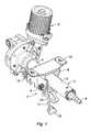
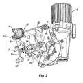
- An example of a steering column adjustment mechanismis illustrated on the figures 1 and 2 of the accompanying drawing, the adjustment mechanism shown here being applied to a steering column 2 of a vehicle with power assist device 3 of the steering, the assistance device 3 acting on the lower part of the steering column 2 .
- This steering column 2comprises an inner tube 4 forming the lower part of the column, and an outer tube 5 forming the upper part of the column, at the top of which exceeds a connecting element 6 with the steering wheel (not shown). .
- the outer tube 5is mounted to slide axially on the inner tube 4, for the adjustment of the depth of the steering wheel.
- the adjustment mechanismdesignated as a whole by the reference 7, is associated with an upper fastening flange 8 of the steering column 2.
- This adjustment mechanism 7comprises a transverse axis 9, extending under the tube 5 and at the through the flange 8, the axis 9 carrying in its central part a cam 10, and being connected laterally to a control lever 11, ending in a handle 12.
- the transverse axis 9 of the adjusting mechanism 7comprises a slide connection, substantially vertical, with the upper fastening flange 8 of the steering column 2.
- This transverse axis 9comprises another slide-type connection, parallel to the axis of the steering column 2, with a lower flange 13 which is inserted into the upper fastening flange 8 and which is integral with the outer tube 5.
- the locking of the steering column 2, in the set positionis performed by pivoting the control lever 11 and also the axis 9 until abutting, thereby creating by means of cams, on the one hand, a nip between the lower flange 13 and the upper attachment flange 8, and on the other hand, a pressure exerted by the cam 10 on the inner tube 4, through an opening 14 of the outer tube 5.
- the inner tube 4then bears against the outer tube 5.
- the mechanism 7is thus blocked in all directions, which keeps the set position.
- certain steering columnsalso have an energy absorption function in the event of an impact on the vehicle. This function is performed by retraction, in particular between firstly the outer tube 5 and the upper fastening flange 8 of the steering column 2 secured to one another by the locking mechanism 7, and other A set of detachable cells 15 provided at the fixing points of the upper flange 8 on the steering column support (not shown) connected to the vehicle structure.
- connectionis sliding at the level of the mechanism 7, that is to say if in the locked position the axial force of maintaining the telescopic adjustment is less than the disengagement force of the detachable cells 15, the outer tube 5 secured to the lower flange 13 is first supported on the transverse axis 9, before the detachable cells 15 unhook.
- the retraction functionthus produced, allows in particular incas of frontal impact of the vehicle to dampen the impact of the driver on the steering wheel by a compression of the steering column 2 over part of its length.
- the absorption of the impact energyis here carried out according to a force / displacement curve to be adjusted on the basis of impact tests carried out using a manikin; this curve is characterized in particular by the value of the offset force on the beginning of the curve, and by the ratio effort / displacement on the remainder of the curve.
- the present inventionaims to avoid this disadvantage, and it therefore aims to provide a solution preventing a fall of the steering column at the time of adjustment, even in case of significant effort applied to the steering wheel and transmitted to this column, and this despite the presence of detachable cells between the upper attachment flange and the steering column support.
- the subject of the inventionis a mechanism for adjusting a steering column of a motor vehicle, the steering column comprising an inner tube and an outer tube mounted to slide axially on the inner tube, and the adjusting mechanism comprising an upper fastening flange, a lower flange inserted in the upper fastening flange and a transverse axle provided with a cam and a control lever, said axle passing through the two flanges and the cam being provided to cooperate with the inner barrel; passing through an opening of the outer tube for locking in a set position, by pressing the inner tube against the outer tube, while in an unlocked position resulting from a rotation of the transverse axis the cam releases the support of the inner tube against the outer tube, this adjustment mechanism being characterized in that are associated with the cam, on the transverse axis l, temporary longitudinal locking means of the upper fixing flange relative to the inner tube, these locking means being deactivated in the locking position.
- the temporary locking meansconsist of a lug protruding radially from the transverse axis, at the level of the cam, and intended to be introduced into a hole provided in the inner tube, when the aforementioned axis is rotated with its cam to the unlocked position.
- the idea underlying the present inventionis to modify or adapt the cam carried by the transverse axis, by adding a pin or other mechanical member whose function is the achievement of a longitudinal locking of the upper flange of the adjustment mechanism on the inner tube, which lock is activated only when the cam rotates during the unlocking operation, performed for the purpose of adjusting the position of the steering wheel by the driver.
- the temporary blockingthus produced makes it possible to withstand a major force or impact applied to the steering wheel along the axis of the column of direction, regardless of the stress of the energy absorption system of this steering column, as a result of the detachable cells associated with the fastening flange.
- a lug 16is integral in rotation with the cam 10, thus also with the transverse axis 9.
- the lug 16extends essentially in a radial orientation, relative to the axis 9, the free end this lug 16 can be bent to form a kind of hook.
- the inner tube 4 of the steering column 2has a hole 17, formed in its wall facing the opening 14 of the outer tube 5, and also opposite the lug 16.
- the lug 16pivots with the axis 9 and thus engages, through the opening 14 of the outer tube 5, in the hole 17 of the inner tube 4.
- the lug 16blocks the longitudinal translation of the fastening flange 8 with respect to the inner tube 4.
- the type connection vertical slide made between the axis 9 and the fastening flange 8has no clearance with respect to this fastening flange, in the axial direction of the steering column, thus making the axis 9 integral with the tube 4 through the pin 16 causes, through this axis 9, the longitudinal locking of the fastening flange 8.
- the temporary immobilizationthus obtained allows the steering column 2 to withstand a high effort or a shock applied to the steering wheel, in the unlocked position of the steering column 2 and in particular during the adjustment operation by the mechanism 7.
Landscapes
- Engineering & Computer Science (AREA)
- Chemical & Material Sciences (AREA)
- Combustion & Propulsion (AREA)
- Transportation (AREA)
- Mechanical Engineering (AREA)
- Steering Controls (AREA)
Description
Translated fromFrenchLa présente invention se rapporte, d'une manière générale, aux systèmes de direction des véhicules automobiles. Cette invention s'intéresse plus précisément aux colonnes de direction et elle concerne, encore plus particulièrement, un mécanisme de réglage d'une colonne de direction de véhicule automobile.The present invention relates, in general, to the steering systems of motor vehicles. This invention is more specifically concerned with steering columns and more particularly relates to a mechanism for adjusting a steering column of a motor vehicle.
Certaines colonnes de direction équipant les véhicules automobiles possèdent un mécanisme de réglage, qui permet de modifier la position du volant de conduite en hauteur et en profondeur, de manière à l'adapter au mieux à la taille du conducteur du véhicule, et à sa position de conduite. Un exemple de mécanisme de réglage d'une colonne de direction est illustré sur les
Cette colonne de direction 2 comporte un tube intérieur 4 formant la partie basse de la colonne, et un tube extérieur 5 formant la partie haute de la colonne, au sommet de laquelle dépasse un élément 6 de liaison avec le volant de conduite (non représenté). Le tube extérieur 5 est monté coulissant axialement sur le tube intérieur 4, pour le réglage en profondeur de la position du volant.This
Le mécanisme de réglage, désigné dans son ensemble par la référence 7, est associé à une bride de fixation supérieure 8 de la colonne de direction 2. Ce mécanisme de réglage 7 comprend un axe transversal 9, s'étendant sous le tube 5 et au travers de la bride 8, l'axe 9 portant dans sa partie centrale une came 10, et étant relié latéralement à un levier de commande 11, se terminant par une poignée 12.The adjustment mechanism, designated as a whole by the
L'axe transversal 9 du mécanisme de réglage 7 comporte une liaison de type glissière, sensiblement verticale, avec la bride de fixation supérieure 8 de la colonne de direction 2. Cet axe transversal 9 comporte une autre liaison de type glissière, parallèle à l'axe de la colonne de direction 2, avec une bride inférieure 13 qui est insérée dans la bride de fixation supérieure 8 et qui est solidaire du tube extérieur 5.The
Le verrouillage de la colonne de direction 2, dans la position réglée, s'effectue en faisant pivoter le levier de commande 11 donc aussi l'axe 9jusqu'en butée, en créant ainsi par l'intermédiaire de cames, d'une part, un pincement entre la bride inférieure 13 et la bride de fixation supérieure 8, et d'autre part, une pression exercée par la came 10 sur le tube intérieur 4, au travers d'une ouverture 14 du tube extérieur 5. Le tube intérieur 4 vient alors en appui contre le tube extérieur 5. Le mécanisme 7 est ainsi bloqué en tous sens, ce qui permet de conserver la position réglée.The locking of the
Le document de brevet
Comme l'illustrent aussi les
Lorsqu'elles combinent un mécanisme de réglage tel que décrit précédemment, et une fonction de rétraction réalisée comme il vient d'être rappelé ou analogue, les colonnes de direction existantes présentent un inconvénient, qui se manifeste lors de l'opération de réglage de la position du volant, la colonne de direction étant alors déverrouillée.When combining a control mechanism as described above, and a retraction function performed as just recalled or the like, the existing steering columns have a disadvantage, which is manifested during the adjustment operation of the position of the steering wheel, the steering column then being unlocked.
A ce moment, si le conducteur pousse ou tire brusquement le volant, donc la colonne de direction, et que celle-ci vient heurter sa butée télescopique de fin de course, l'effort ainsi créé sur la colonne peut dépasser l'effort de décrochement du système d'absorption d'énergie à cellules détachables, et la colonne de direction qui n'est alors plus tenue peut tomber sur les genoux du conducteur, avec les risques de blessure que cela comporte, à ceci s'ajoutant le problème de la remise en place de la colonne de direction.At this moment, if the driver pushes or pulls suddenly the steering wheel, and therefore the steering column, and that it collides with its telescopic limit stop, the force thus created on the column may exceed the offset force. detachable cells energy absorption system, and the steering column which is no longer held can fall on the driver's lap, with the risk of injury that entails, to this is added the problem of the refitting of the steering column.
La présente invention vise à éviter cet inconvénient, et elle a donc pour but de proposer une solution empêchant une tombée de la colonne de direction au moment du réglage, même en cas d'effort important appliqué sur le volant et transmis à cette colonne, et ceci malgré la présence de cellules détachables entre la bride de fixation supérieure et le support de colonne de direction.The present invention aims to avoid this disadvantage, and it therefore aims to provide a solution preventing a fall of the steering column at the time of adjustment, even in case of significant effort applied to the steering wheel and transmitted to this column, and this despite the presence of detachable cells between the upper attachment flange and the steering column support.
A cet effet, l'invention a pour objet un mécanisme de réglage d'une colonne de direction de véhicule automobile, la colonne de direction comprenant un tube intérieur et un tube extérieur monté coulissant axialement sur le tube intérieur, et le mécanisme de réglage comprenant une bride de fixationsupérieure, une bride inférieure insérée dans la bride de fixation supérieure et un axe transversal muni d'une came et d'un levier de commande, ledit axe traversant les deux brides et la came étant prévue pour coopérer avec le tube intérieur en passant au travers d'une ouverture du tube extérieur en vue de réaliser un verrouillage dans une position réglée, par appui du tube intérieur contre le tube extérieur, tandis que dans une position déverrouillée résultant d'une rotation de l'axe transversal la came libère l'appui du tube intérieur contre le tube extérieur, ce mécanisme de réglage étant caractérisé en ce que sont associés à la came, sur l'axe transversal, des moyens de blocage longitudinal temporaire de la bride de fixation supérieure par rapport au tube intérieur, ces moyens de blocage étant désactivés dans la position de verrouillage.For this purpose, the subject of the invention is a mechanism for adjusting a steering column of a motor vehicle, the steering column comprising an inner tube and an outer tube mounted to slide axially on the inner tube, and the adjusting mechanism comprising an upper fastening flange, a lower flange inserted in the upper fastening flange and a transverse axle provided with a cam and a control lever, said axle passing through the two flanges and the cam being provided to cooperate with the inner barrel; passing through an opening of the outer tube for locking in a set position, by pressing the inner tube against the outer tube, while in an unlocked position resulting from a rotation of the transverse axis the cam releases the support of the inner tube against the outer tube, this adjustment mechanism being characterized in that are associated with the cam, on the transverse axis l, temporary longitudinal locking means of the upper fixing flange relative to the inner tube, these locking means being deactivated in the locking position.
Dans un mode de réalisation préféré de l'invention, particulièrement simple, les moyens de blocage temporaire sont constitués par un ergot saillant radialement de l'axe transversal, au niveau de la came, et prévu pour s'introduire dans un trou prévu dans le tube intérieur , lorsque l'axe précité est tourné avec sa came vers la position déverrouillée.In a particularly preferred embodiment of the invention, which is particularly simple, the temporary locking means consist of a lug protruding radially from the transverse axis, at the level of the cam, and intended to be introduced into a hole provided in the inner tube, when the aforementioned axis is rotated with its cam to the unlocked position.
Ainsi, l'idée à la base de la présente invention consiste à modifier ou adapter la came portée par l'axe transversal, par l'ajout d'un ergot ou autre organe mécanique dont la fonction est la réalisation d'un blocage longitudinal de la bride supérieure du mécanisme de réglage sur le tube intérieur, blocage qui est rendu actif seulement lorsque la came tourne lors de l'opération de déverrouillage, réalisée en vue du réglage de la position du volant par le conducteur. Le blocage temporaire, ainsi réalisé, permet de résister à un effort ou un choc important appliqué sur le volant suivant l'axe de la colonne de direction, indépendamment de l'effort de décrochement du système d'absorption d'énergie de cette colonne de direction, tel qu'il résulte des cellules détachables associées à la bride de fixation.Thus, the idea underlying the present invention is to modify or adapt the cam carried by the transverse axis, by adding a pin or other mechanical member whose function is the achievement of a longitudinal locking of the upper flange of the adjustment mechanism on the inner tube, which lock is activated only when the cam rotates during the unlocking operation, performed for the purpose of adjusting the position of the steering wheel by the driver. The temporary blocking thus produced makes it possible to withstand a major force or impact applied to the steering wheel along the axis of the column of direction, regardless of the stress of the energy absorption system of this steering column, as a result of the detachable cells associated with the fastening flange.
L'invention sera mieux comprise à l'aide de la description qui suit, en référence au dessin schématique annexé représentant, à titre d'exemple, une forme d'exécution de ce mécanisme de réglage d'une colonne de direction de véhicule automobile.
Figures 1 et2 (déjà mentionnées) sont des vues en perspective illustrant des mécanismes de réglage selon l'état de la technique ;Figure 3 est une vue en coupe passant par l'axe d'une colonne de direction avec son mécanisme de réglage conforme à la présente invention, représenté en position verrouillée ;Figure 4 est une vue en coupe similaire à lafigure 3 , mais représentant le mécanisme de réglage dans la position déverrouillée.- Les
figures 3 et 4 montrent partiellement une colonne dedirection 2 avec son mécanisme deréglage 7, les éléments correspondant à ceux précédemment décrits (en référence auxfigures 1 et2 ) étant désignés par les mêmes références numériques et ne faisant pas ici l'objet d'une nouvelle description.
Figures 1 and2 (already mentioned) are perspective views illustrating adjustment mechanisms according to the state of the art;Figure 3 is a sectional view through the axis of a steering column with its adjustment mechanism according to the present invention, shown in locked position;Figure 4 is a sectional view similar to thefigure 3 but representing the adjustment mechanism in the unlocked position.- The
Figures 3 and 4 partially show asteering column 2 with itsadjustment mechanism 7, the elements corresponding to those previously described (with reference tofigures 1 and2 ) being designated by the same reference numerals and not being the subject of a new description here.
Selon l'invention, un ergot 16 est solidaire en rotation de la came 10, donc aussi de l'axe transversal 9. L'ergot 16 s'étend essentiellement dans une orientation radiale, relativement à l'axe 9, l'extrémité libre de cet ergot 16 pouvant être coudée pour former une sorte de crochet.According to the invention, a
Le tube intérieur 4 de la colonne de direction 2 comporte un trou 17, ménagé dans sa paroi en regard de l'ouverture 14 du tube extérieur 5, et aussi en regard de l'ergot 16.The
En position verrouillée, comme montré sur la
Lors de déverrouillage de la colonne de direction 2 par actionnement en rotation du levier de commande 11 avec poignée 12 selon la flèche F, comme le montre la
On ne s'écarterait pas du cadre de l'invention, telle que définie dans les revendications annexes :
- en adaptant la solution ici proposée, en particulier la forme de l'ergot, selon le sens de la rotation du levier de commande utilisé pour verrouiller le mécanisme, sachant qu'on peut effectuer le verrouillage en poussant sur le levier ou en tirant sur le levier, selon les réalisations ;
- en appliquant l'invention à des colonnes de direction dont le mécanisme de réglage ou le système d'absorption d'énergie par rétraction différeraient quelque peu de ceux ici décrits ;
- en destinant ce mécanisme de réglage à des systèmes de direction de tous types, assistées ou non, et avec tout genre d'assistance électrique ou hydraulique dans le cas de directions assistées.
- adapting the solution proposed here, in particular the shape of the pin, according to the direction of rotation of the control lever used to lock the mechanism, knowing that the locking can be done by pushing on the lever or by pulling on the lever. leverage, according to the achievements;
- applying the invention to steering columns whose adjustment mechanism or retraction energy absorption system differ somewhat from those described herein;
- by assigning this adjustment mechanism to steering systems of all types, assisted or not, and with any kind of electrical or hydraulic assistance in the case of power steering.
Claims (2)
- A mechanism (7) for adjusting a motor vehicle steering column (2), the steering column (2) comprising an inner tube (4) and an outer tube (5) axially slidingly mounted on the inner tube (4), and the steering mechanism (7) comprising an upper fastening flange (8), a lower flange (13) inserted into the upper fastening flange (8), and a transverse axis (9) provided with a cam (10) and a control lever (11, 12), said axis (9) passing through the two flanges (8, 13) and the cam (10) being provided to cooperate with the inner tube (4) by passing through an opening (14) of the outer tube (5) so as to perform locking in an adjusted position, by bearing of the inner tube (4) against the outer tube (5), while in an unlocked position resulting from a rotation of the transverse axis (9), the cam (10) frees the bearing of the inner tube (4) against the outer tube (5),characterized in that associated with the cam (10), on the transverse axis (9), are means (16) for temporary longitudinal blocking of the upper fastening flange (8) relative to the inner tube (4), said blocking means being deactivated in the locking position.
- The adjustment mechanism according to claim 1,characterized in that the temporary blocking means are made up of a lug (16) radially protruding from the transverse axis (9), at the cam (10), and provided to be inserted into a hole (17) provided in the inner tube (4), when the axis (9) is turned with its cam (10) toward the unlocked position.
Applications Claiming Priority (1)
| Application Number | Priority Date | Filing Date | Title |
|---|---|---|---|
| FR1052787AFR2958614B1 (en) | 2010-04-13 | 2010-04-13 | MECHANISM FOR ADJUSTING A STEERING COLUMN FOR A MOTOR VEHICLE |
Publications (2)
| Publication Number | Publication Date |
|---|---|
| EP2377742A1 EP2377742A1 (en) | 2011-10-19 |
| EP2377742B1true EP2377742B1 (en) | 2012-09-19 |
Family
ID=42306720
Family Applications (1)
| Application Number | Title | Priority Date | Filing Date |
|---|---|---|---|
| EP11160607ANot-in-forceEP2377742B1 (en) | 2010-04-13 | 2011-03-31 | Mechanism for adjusting a steering column of a vehicle |
Country Status (2)
| Country | Link |
|---|---|
| EP (1) | EP2377742B1 (en) |
| FR (1) | FR2958614B1 (en) |
Families Citing this family (3)
| Publication number | Priority date | Publication date | Assignee | Title |
|---|---|---|---|---|
| DE102011056351A1 (en)* | 2011-12-13 | 2013-06-13 | Zf Lenksysteme Gmbh | Steering column for steering system of vehicle, has guide tube, which is adjusted along its longitudinal axis, where guide tube has block, and control lever is provided for setting situation for adjusting guide tube |
| FR3011798B1 (en) | 2013-10-10 | 2015-10-30 | Renault Sas | STEERING COLUMN ADJUSTMENT SYSTEM |
| DE102014016510B4 (en) | 2014-11-10 | 2016-02-18 | Thyssenkrupp Ag | Steering column with longitudinal stop with adjustable release function for crash |
Citations (1)
| Publication number | Priority date | Publication date | Assignee | Title |
|---|---|---|---|---|
| WO2010122958A1 (en)* | 2009-04-20 | 2010-10-28 | 日本精工株式会社 | Position adjustment device for steering wheel |
Family Cites Families (3)
| Publication number | Priority date | Publication date | Assignee | Title |
|---|---|---|---|---|
| JP4882127B2 (en)* | 2005-11-16 | 2012-02-22 | 株式会社ジェイテクト | Position adjustment type steering device |
| GB0721238D0 (en)* | 2007-10-30 | 2007-12-05 | Trw Ltd | Steering column assembly |
| KR101031627B1 (en)* | 2007-10-31 | 2011-04-27 | 후지키코 가부시키가이샤 | Steering column unit |
- 2010
- 2010-04-13FRFR1052787Apatent/FR2958614B1/ennot_activeExpired - Fee Related
- 2011
- 2011-03-31EPEP11160607Apatent/EP2377742B1/ennot_activeNot-in-force
Patent Citations (2)
| Publication number | Priority date | Publication date | Assignee | Title |
|---|---|---|---|---|
| WO2010122958A1 (en)* | 2009-04-20 | 2010-10-28 | 日本精工株式会社 | Position adjustment device for steering wheel |
| US20110185839A1 (en)* | 2009-04-20 | 2011-08-04 | Nsk Ltd. | Position adjustment device for steering wheel |
Also Published As
| Publication number | Publication date |
|---|---|
| FR2958614A1 (en) | 2011-10-14 |
| EP2377742A1 (en) | 2011-10-19 |
| FR2958614B1 (en) | 2012-03-16 |
Similar Documents
| Publication | Publication Date | Title |
|---|---|---|
| EP2109701B1 (en) | Device for a pavement manhole with a support frame for closing a panel hinged on the frame using permanent articulation means | |
| EP2296956A1 (en) | Improved adjustable steering column for motor vehicles | |
| WO2010116092A1 (en) | Motor vehicle pedal having a safety device | |
| EP1479578B1 (en) | Pedal assembly that is retractable in the case of a frontal impact on a vehicle | |
| EP2244929B1 (en) | Device or attaching a first sub-assembly to a second sub-assembly in an automobile | |
| EP2377742B1 (en) | Mechanism for adjusting a steering column of a vehicle | |
| EP3071856B1 (en) | Means for blind attachment of brake cable butted end with elastic intermediate lock means | |
| EP0179690B1 (en) | Steering column adjusting device for automotive vehicle | |
| EP3381753B1 (en) | Tilting buckle | |
| EP2009205B1 (en) | Hold-open mechanism handle, in particular for an automobile, trailer or semi-trailer | |
| EP3885592B1 (en) | Arrangement for blind mounting of a brake cable on an actuating lever of a motor vehicle drum brake and mounting method | |
| EP2380797B1 (en) | Steering column with telescopic adjustment mechanism and/or energy-absorbing function by retraction | |
| FR2881707A1 (en) | Instantaneous energy absorption device for steering column of motor vehicle, has movable unit moving with tube-body and steering wheel with respect to fixed unit, towards front of vehicle in case of impact, while absorbing required energy | |
| EP1108636B1 (en) | Steering column assembly with a stationary central pad | |
| EP2322407B1 (en) | Improved device for locking in position an adjustable steering column of a vehicle | |
| EP0223640A1 (en) | Towed vehicle provided with an extendible hitch | |
| EP2556974B1 (en) | Hitch arrangement for a tow vehicle, comprising a hook body for receiving a coupling member of a towed vehicle | |
| FR2928617A1 (en) | Adjustable telescopic stand for parking motorcycle, has lock configured such that lock leaves from and remains in housing by exerting force directed towards bottom and top, on tube, respectively, when lock is in position inside housing | |
| EP3124328A1 (en) | Roof bar | |
| EP3122576B1 (en) | Motor vehicle comprising running gear attachment guide means | |
| WO2024156558A1 (en) | Steering column comprising a system for both user adjustment and for absorbing energy in the event of an accident | |
| FR2815928A1 (en) | Bicycle handlebar stem assembly comprises sleeve surrounding fork pivot and projecting tubular part with handlebar fixing, upper and lower bearings between steering column and pivot provide steering play | |
| EP2322406B1 (en) | Simplified device for locking in position an adjustable steering column of a vehicle | |
| FR2981607A1 (en) | DEVICE FOR FIXING AN ONBOARD OBJECT AT THE BACK OF A VEHICLE | |
| FR2952015A1 (en) | Vehicle, has adjusting unit including bearing in which one of two columns is mounted, where adjusting unit includes yoke articulated on vehicle structure and carrying bearing which is pivotally attached to yoke |
Legal Events
| Date | Code | Title | Description |
|---|---|---|---|
| AK | Designated contracting states | Kind code of ref document:A1 Designated state(s):AL AT BE BG CH CY CZ DE DK EE ES FI FR GB GR HR HU IE IS IT LI LT LU LV MC MK MT NL NO PL PT RO RS SE SI SK SM TR | |
| AX | Request for extension of the european patent | Extension state:BA ME | |
| PUAI | Public reference made under article 153(3) epc to a published international application that has entered the european phase | Free format text:ORIGINAL CODE: 0009012 | |
| 17P | Request for examination filed | Effective date:20111221 | |
| GRAP | Despatch of communication of intention to grant a patent | Free format text:ORIGINAL CODE: EPIDOSNIGR1 | |
| RIC1 | Information provided on ipc code assigned before grant | Ipc:B62D 1/184 20060101AFI20120316BHEP | |
| GRAS | Grant fee paid | Free format text:ORIGINAL CODE: EPIDOSNIGR3 | |
| GRAA | (expected) grant | Free format text:ORIGINAL CODE: 0009210 | |
| AK | Designated contracting states | Kind code of ref document:B1 Designated state(s):AL AT BE BG CH CY CZ DE DK EE ES FI FR GB GR HR HU IE IS IT LI LT LU LV MC MK MT NL NO PL PT RO RS SE SI SK SM TR | |
| REG | Reference to a national code | Ref country code:GB Ref legal event code:FG4D Free format text:NOT ENGLISH | |
| REG | Reference to a national code | Ref country code:CH Ref legal event code:EP | |
| REG | Reference to a national code | Ref country code:IE Ref legal event code:FG4D Free format text:LANGUAGE OF EP DOCUMENT: FRENCH | |
| REG | Reference to a national code | Ref country code:AT Ref legal event code:REF Ref document number:575845 Country of ref document:AT Kind code of ref document:T Effective date:20121015 | |
| REG | Reference to a national code | Ref country code:DE Ref legal event code:R096 Ref document number:602011000240 Country of ref document:DE Effective date:20121115 | |
| PG25 | Lapsed in a contracting state [announced via postgrant information from national office to epo] | Ref country code:FI Free format text:LAPSE BECAUSE OF FAILURE TO SUBMIT A TRANSLATION OF THE DESCRIPTION OR TO PAY THE FEE WITHIN THE PRESCRIBED TIME-LIMIT Effective date:20120919 Ref country code:HR Free format text:LAPSE BECAUSE OF FAILURE TO SUBMIT A TRANSLATION OF THE DESCRIPTION OR TO PAY THE FEE WITHIN THE PRESCRIBED TIME-LIMIT Effective date:20120919 Ref country code:NO Free format text:LAPSE BECAUSE OF FAILURE TO SUBMIT A TRANSLATION OF THE DESCRIPTION OR TO PAY THE FEE WITHIN THE PRESCRIBED TIME-LIMIT Effective date:20121219 Ref country code:LT Free format text:LAPSE BECAUSE OF FAILURE TO SUBMIT A TRANSLATION OF THE DESCRIPTION OR TO PAY THE FEE WITHIN THE PRESCRIBED TIME-LIMIT Effective date:20120919 | |
| REG | Reference to a national code | Ref country code:NL Ref legal event code:VDEP Effective date:20120919 | |
| REG | Reference to a national code | Ref country code:AT Ref legal event code:MK05 Ref document number:575845 Country of ref document:AT Kind code of ref document:T Effective date:20120919 | |
| REG | Reference to a national code | Ref country code:LT Ref legal event code:MG4D Effective date:20120919 | |
| PG25 | Lapsed in a contracting state [announced via postgrant information from national office to epo] | Ref country code:SE Free format text:LAPSE BECAUSE OF FAILURE TO SUBMIT A TRANSLATION OF THE DESCRIPTION OR TO PAY THE FEE WITHIN THE PRESCRIBED TIME-LIMIT Effective date:20120919 Ref country code:GR Free format text:LAPSE BECAUSE OF FAILURE TO SUBMIT A TRANSLATION OF THE DESCRIPTION OR TO PAY THE FEE WITHIN THE PRESCRIBED TIME-LIMIT Effective date:20121220 Ref country code:LV Free format text:LAPSE BECAUSE OF FAILURE TO SUBMIT A TRANSLATION OF THE DESCRIPTION OR TO PAY THE FEE WITHIN THE PRESCRIBED TIME-LIMIT Effective date:20120919 Ref country code:SI Free format text:LAPSE BECAUSE OF FAILURE TO SUBMIT A TRANSLATION OF THE DESCRIPTION OR TO PAY THE FEE WITHIN THE PRESCRIBED TIME-LIMIT Effective date:20120919 | |
| PG25 | Lapsed in a contracting state [announced via postgrant information from national office to epo] | Ref country code:NL Free format text:LAPSE BECAUSE OF FAILURE TO SUBMIT A TRANSLATION OF THE DESCRIPTION OR TO PAY THE FEE WITHIN THE PRESCRIBED TIME-LIMIT Effective date:20120919 Ref country code:EE Free format text:LAPSE BECAUSE OF FAILURE TO SUBMIT A TRANSLATION OF THE DESCRIPTION OR TO PAY THE FEE WITHIN THE PRESCRIBED TIME-LIMIT Effective date:20120919 Ref country code:RO Free format text:LAPSE BECAUSE OF FAILURE TO SUBMIT A TRANSLATION OF THE DESCRIPTION OR TO PAY THE FEE WITHIN THE PRESCRIBED TIME-LIMIT Effective date:20120919 Ref country code:IS Free format text:LAPSE BECAUSE OF FAILURE TO SUBMIT A TRANSLATION OF THE DESCRIPTION OR TO PAY THE FEE WITHIN THE PRESCRIBED TIME-LIMIT Effective date:20130119 | |
| PG25 | Lapsed in a contracting state [announced via postgrant information from national office to epo] | Ref country code:PT Free format text:LAPSE BECAUSE OF FAILURE TO SUBMIT A TRANSLATION OF THE DESCRIPTION OR TO PAY THE FEE WITHIN THE PRESCRIBED TIME-LIMIT Effective date:20130121 Ref country code:SK Free format text:LAPSE BECAUSE OF FAILURE TO SUBMIT A TRANSLATION OF THE DESCRIPTION OR TO PAY THE FEE WITHIN THE PRESCRIBED TIME-LIMIT Effective date:20120919 Ref country code:PL Free format text:LAPSE BECAUSE OF FAILURE TO SUBMIT A TRANSLATION OF THE DESCRIPTION OR TO PAY THE FEE WITHIN THE PRESCRIBED TIME-LIMIT Effective date:20120919 | |
| PG25 | Lapsed in a contracting state [announced via postgrant information from national office to epo] | Ref country code:AT Free format text:LAPSE BECAUSE OF FAILURE TO SUBMIT A TRANSLATION OF THE DESCRIPTION OR TO PAY THE FEE WITHIN THE PRESCRIBED TIME-LIMIT Effective date:20120919 | |
| PLBE | No opposition filed within time limit | Free format text:ORIGINAL CODE: 0009261 | |
| STAA | Information on the status of an ep patent application or granted ep patent | Free format text:STATUS: NO OPPOSITION FILED WITHIN TIME LIMIT | |
| PG25 | Lapsed in a contracting state [announced via postgrant information from national office to epo] | Ref country code:BG Free format text:LAPSE BECAUSE OF FAILURE TO SUBMIT A TRANSLATION OF THE DESCRIPTION OR TO PAY THE FEE WITHIN THE PRESCRIBED TIME-LIMIT Effective date:20121219 Ref country code:RS Free format text:LAPSE BECAUSE OF FAILURE TO SUBMIT A TRANSLATION OF THE DESCRIPTION OR TO PAY THE FEE WITHIN THE PRESCRIBED TIME-LIMIT Effective date:20120919 Ref country code:DK Free format text:LAPSE BECAUSE OF FAILURE TO SUBMIT A TRANSLATION OF THE DESCRIPTION OR TO PAY THE FEE WITHIN THE PRESCRIBED TIME-LIMIT Effective date:20120919 | |
| 26N | No opposition filed | Effective date:20130620 | |
| PG25 | Lapsed in a contracting state [announced via postgrant information from national office to epo] | Ref country code:IT Free format text:LAPSE BECAUSE OF FAILURE TO SUBMIT A TRANSLATION OF THE DESCRIPTION OR TO PAY THE FEE WITHIN THE PRESCRIBED TIME-LIMIT Effective date:20120919 | |
| BERE | Be: lapsed | Owner name:JTEKT EUROPE Effective date:20130331 | |
| REG | Reference to a national code | Ref country code:DE Ref legal event code:R097 Ref document number:602011000240 Country of ref document:DE Effective date:20130620 | |
| PG25 | Lapsed in a contracting state [announced via postgrant information from national office to epo] | Ref country code:ES Free format text:LAPSE BECAUSE OF FAILURE TO SUBMIT A TRANSLATION OF THE DESCRIPTION OR TO PAY THE FEE WITHIN THE PRESCRIBED TIME-LIMIT Effective date:20121230 Ref country code:MC Free format text:LAPSE BECAUSE OF NON-PAYMENT OF DUE FEES Effective date:20130331 | |
| PG25 | Lapsed in a contracting state [announced via postgrant information from national office to epo] | Ref country code:CY Free format text:LAPSE BECAUSE OF FAILURE TO SUBMIT A TRANSLATION OF THE DESCRIPTION OR TO PAY THE FEE WITHIN THE PRESCRIBED TIME-LIMIT Effective date:20120919 | |
| REG | Reference to a national code | Ref country code:IE Ref legal event code:MM4A | |
| PG25 | Lapsed in a contracting state [announced via postgrant information from national office to epo] | Ref country code:AL Free format text:LAPSE BECAUSE OF FAILURE TO SUBMIT A TRANSLATION OF THE DESCRIPTION OR TO PAY THE FEE WITHIN THE PRESCRIBED TIME-LIMIT Effective date:20120919 Ref country code:BE Free format text:LAPSE BECAUSE OF NON-PAYMENT OF DUE FEES Effective date:20130331 Ref country code:IE Free format text:LAPSE BECAUSE OF NON-PAYMENT OF DUE FEES Effective date:20130331 | |
| PGFP | Annual fee paid to national office [announced via postgrant information from national office to epo] | Ref country code:CZ Payment date:20140219 Year of fee payment:4 | |
| PG25 | Lapsed in a contracting state [announced via postgrant information from national office to epo] | Ref country code:MT Free format text:LAPSE BECAUSE OF FAILURE TO SUBMIT A TRANSLATION OF THE DESCRIPTION OR TO PAY THE FEE WITHIN THE PRESCRIBED TIME-LIMIT Effective date:20120919 | |
| REG | Reference to a national code | Ref country code:CH Ref legal event code:PL | |
| PG25 | Lapsed in a contracting state [announced via postgrant information from national office to epo] | Ref country code:CH Free format text:LAPSE BECAUSE OF NON-PAYMENT OF DUE FEES Effective date:20140331 Ref country code:LI Free format text:LAPSE BECAUSE OF NON-PAYMENT OF DUE FEES Effective date:20140331 | |
| PG25 | Lapsed in a contracting state [announced via postgrant information from national office to epo] | Ref country code:SM Free format text:LAPSE BECAUSE OF FAILURE TO SUBMIT A TRANSLATION OF THE DESCRIPTION OR TO PAY THE FEE WITHIN THE PRESCRIBED TIME-LIMIT Effective date:20120919 | |
| PG25 | Lapsed in a contracting state [announced via postgrant information from national office to epo] | Ref country code:TR Free format text:LAPSE BECAUSE OF FAILURE TO SUBMIT A TRANSLATION OF THE DESCRIPTION OR TO PAY THE FEE WITHIN THE PRESCRIBED TIME-LIMIT Effective date:20120919 | |
| PG25 | Lapsed in a contracting state [announced via postgrant information from national office to epo] | Ref country code:LU Free format text:LAPSE BECAUSE OF NON-PAYMENT OF DUE FEES Effective date:20130331 Ref country code:HU Free format text:LAPSE BECAUSE OF FAILURE TO SUBMIT A TRANSLATION OF THE DESCRIPTION OR TO PAY THE FEE WITHIN THE PRESCRIBED TIME-LIMIT; INVALID AB INITIO Effective date:20110331 Ref country code:MK Free format text:LAPSE BECAUSE OF FAILURE TO SUBMIT A TRANSLATION OF THE DESCRIPTION OR TO PAY THE FEE WITHIN THE PRESCRIBED TIME-LIMIT Effective date:20120919 | |
| PG25 | Lapsed in a contracting state [announced via postgrant information from national office to epo] | Ref country code:CZ Free format text:LAPSE BECAUSE OF NON-PAYMENT OF DUE FEES Effective date:20150331 | |
| REG | Reference to a national code | Ref country code:FR Ref legal event code:PLFP Year of fee payment:6 | |
| REG | Reference to a national code | Ref country code:FR Ref legal event code:PLFP Year of fee payment:7 | |
| REG | Reference to a national code | Ref country code:FR Ref legal event code:PLFP Year of fee payment:8 | |
| PGFP | Annual fee paid to national office [announced via postgrant information from national office to epo] | Ref country code:GB Payment date:20190207 Year of fee payment:9 | |
| GBPC | Gb: european patent ceased through non-payment of renewal fee | Effective date:20200331 | |
| PG25 | Lapsed in a contracting state [announced via postgrant information from national office to epo] | Ref country code:GB Free format text:LAPSE BECAUSE OF NON-PAYMENT OF DUE FEES Effective date:20200331 | |
| PGFP | Annual fee paid to national office [announced via postgrant information from national office to epo] | Ref country code:FR Payment date:20210129 Year of fee payment:11 | |
| PGFP | Annual fee paid to national office [announced via postgrant information from national office to epo] | Ref country code:DE Payment date:20210129 Year of fee payment:11 | |
| REG | Reference to a national code | Ref country code:DE Ref legal event code:R119 Ref document number:602011000240 Country of ref document:DE | |
| PG25 | Lapsed in a contracting state [announced via postgrant information from national office to epo] | Ref country code:FR Free format text:LAPSE BECAUSE OF NON-PAYMENT OF DUE FEES Effective date:20220331 Ref country code:DE Free format text:LAPSE BECAUSE OF NON-PAYMENT OF DUE FEES Effective date:20221001 |