EP2377457A1 - Medical device - Google Patents
Medical deviceDownload PDFInfo
- Publication number
- EP2377457A1 EP2377457A1EP10827686AEP10827686AEP2377457A1EP 2377457 A1EP2377457 A1EP 2377457A1EP 10827686 AEP10827686 AEP 10827686AEP 10827686 AEP10827686 AEP 10827686AEP 2377457 A1EP2377457 A1EP 2377457A1
- Authority
- EP
- European Patent Office
- Prior art keywords
- distal end
- end portion
- medical apparatus
- image
- bending
- Prior art date
- Legal status (The legal status is an assumption and is not a legal conclusion. Google has not performed a legal analysis and makes no representation as to the accuracy of the status listed.)
- Granted
Links
Images


Classifications
- A—HUMAN NECESSITIES
- A61—MEDICAL OR VETERINARY SCIENCE; HYGIENE
- A61B—DIAGNOSIS; SURGERY; IDENTIFICATION
- A61B1/00—Instruments for performing medical examinations of the interior of cavities or tubes of the body by visual or photographical inspection, e.g. endoscopes; Illuminating arrangements therefor
- A61B1/267—Instruments for performing medical examinations of the interior of cavities or tubes of the body by visual or photographical inspection, e.g. endoscopes; Illuminating arrangements therefor for the respiratory tract, e.g. laryngoscopes, bronchoscopes
- A61B1/2676—Bronchoscopes
- A—HUMAN NECESSITIES
- A61—MEDICAL OR VETERINARY SCIENCE; HYGIENE
- A61B—DIAGNOSIS; SURGERY; IDENTIFICATION
- A61B1/00—Instruments for performing medical examinations of the interior of cavities or tubes of the body by visual or photographical inspection, e.g. endoscopes; Illuminating arrangements therefor
- A61B1/04—Instruments for performing medical examinations of the interior of cavities or tubes of the body by visual or photographical inspection, e.g. endoscopes; Illuminating arrangements therefor combined with photographic or television appliances
- A61B1/05—Instruments for performing medical examinations of the interior of cavities or tubes of the body by visual or photographical inspection, e.g. endoscopes; Illuminating arrangements therefor combined with photographic or television appliances characterised by the image sensor, e.g. camera, being in the distal end portion
- A—HUMAN NECESSITIES
- A61—MEDICAL OR VETERINARY SCIENCE; HYGIENE
- A61B—DIAGNOSIS; SURGERY; IDENTIFICATION
- A61B34/00—Computer-aided surgery; Manipulators or robots specially adapted for use in surgery
- A61B34/20—Surgical navigation systems; Devices for tracking or guiding surgical instruments, e.g. for frameless stereotaxis
- A—HUMAN NECESSITIES
- A61—MEDICAL OR VETERINARY SCIENCE; HYGIENE
- A61B—DIAGNOSIS; SURGERY; IDENTIFICATION
- A61B1/00—Instruments for performing medical examinations of the interior of cavities or tubes of the body by visual or photographical inspection, e.g. endoscopes; Illuminating arrangements therefor
- A61B1/00147—Holding or positioning arrangements
- A61B1/00158—Holding or positioning arrangements using magnetic field
- A—HUMAN NECESSITIES
- A61—MEDICAL OR VETERINARY SCIENCE; HYGIENE
- A61B—DIAGNOSIS; SURGERY; IDENTIFICATION
- A61B1/00—Instruments for performing medical examinations of the interior of cavities or tubes of the body by visual or photographical inspection, e.g. endoscopes; Illuminating arrangements therefor
- A61B1/012—Instruments for performing medical examinations of the interior of cavities or tubes of the body by visual or photographical inspection, e.g. endoscopes; Illuminating arrangements therefor characterised by internal passages or accessories therefor
- A61B1/018—Instruments for performing medical examinations of the interior of cavities or tubes of the body by visual or photographical inspection, e.g. endoscopes; Illuminating arrangements therefor characterised by internal passages or accessories therefor for receiving instruments
- A—HUMAN NECESSITIES
- A61—MEDICAL OR VETERINARY SCIENCE; HYGIENE
- A61B—DIAGNOSIS; SURGERY; IDENTIFICATION
- A61B34/00—Computer-aided surgery; Manipulators or robots specially adapted for use in surgery
- A61B34/20—Surgical navigation systems; Devices for tracking or guiding surgical instruments, e.g. for frameless stereotaxis
- A61B2034/2046—Tracking techniques
- A61B2034/2051—Electromagnetic tracking systems
Definitions
- the present inventionrelates to a medical apparatus equipped with a treatment instrument to be inserted into a lumen of a subject to carry out treatment, and more particularly to a medical apparatus which aids a treatment instrument insertion operation using virtual endoscopic images based on three-dimensional image data of the lumen.
- three-dimensional images inside a subjectare obtained by picking up tomograms of the subject using an X-ray CT (Computed Tomography) apparatus and used to carry out diagnosis and the like of a target site.
- X-ray CTComputer Tomography
- the CT apparatusperforms successive scans (helical scans) of the subject continually while rotating X-ray irradiation position and detection position continuously by moving the subject. Then, three-dimensional image data is obtained from a large number of successive two-dimensional tomograms of the subject.
- Examples of the three-dimensional image data used for diagnosis and treatmentinclude three-dimensional image data of the bronchi of the lungs.
- the three-dimensional image data of the bronchi of the lungsis used, for example, to three-dimensionally locate an abnormal site where lung cancer is suspected. Then, to check the abnormal site by a biopsy, an endoscope is inserted into the bronchi, a treatment instrument such as a biopsy needle or biopsy forceps is protruded from a distal end portion of the endoscope, and a sample is taken from the target site.
- Patent Application Laid-Open Publication No. 2009-56238discloses a navigation system which forms three-dimensional images of a lumen based on three-dimensional image data of the subject, determines a route to a target spot along the lumen using the three-dimensional images, further forms and displays virtual endoscopic images of the lumen along the route, and thereby guides insertion operation.
- Patent Application Laid-Open Publication No. 2002-119507discloses a medical apparatus which displays a virtual image viewed from a distal end portion of a catheter inserted in a subject while Patent Application Laid-Open Publication No. 2002-306403 discloses an endoscope apparatus which displays a virtual image of a distal end portion of an endoscope in superimposition on a virtual endoscopic image.
- An object of the present inventionis to provide a medical apparatus allowing a distal end of a treatment instrument to be inserted to a target site in a lumen.
- a medical apparatuscomprising: treatment means provided with a distal end portion, a sensor disposed in the distal end portion and configured to detect a position, a direction and a roll angle, and a bending portion adapted to bend the distal end portion, the distal end portion of the treatment means being allowed to be inserted to a target position in a lumen of a subject; storage means adapted to store three-dimensional image data of the lumen acquired in advance; target position setting means adapted to set the target position based on the three-dimensional image data; virtual endoscopic image generating means adapted to generate a virtual endoscopic image using a line-of-sight parameter which includes the position, the direction, and the roll angle of the distal end portion detected by the sensor, based on the three-dimensional image data; and image processing means adapted to perform a superimposition process and thereby display operation information used to insert the distal end portion to the predetermined position in superimposition on the virtual endoscopic image.
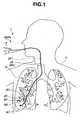
- FIG. 1is a schematic diagram showing how a target site 9G at a bronchial end is biopsied by passing an insertion portion 4E of a treatment instrument 4 through a channel 2F1 of an endoscope 2A of an endoscope apparatus 2 inserted into a bronchus 9 of a patient 7.
- the bronchi 9have multiple bifurcations. Therefore, to insert the treatment instrument 4 to the target site 9G, a surgeon needs to make a correct selection judgment and perform a proper insertion operation at each bifurcation based on an endoscopic image picked up by a CCD 2G (see Fig. 2 ) which is image pickup means in an insertion-portion distal end portion 2C of the endoscope 2A.
- a CCD 2Gsee Fig. 2
- a CMOS or the likemay be used as the image pickup means.
- the medical apparatus 1in addition to the endoscope apparatus 2 and the treatment instrument 4, the medical apparatus 1 includes an insertion aid apparatus 3 adapted to aid the surgeon in making judgments and performing operations. That is, a first function of the insertion aid apparatus 3 is to help the surgeon make selection judgments at bifurcations. A second function of the insertion aid apparatus 3 is to help the surgeon perform bending operation.
- the endoscope apparatus 2includes the insertion-portion distal end portion 2C, a bending portion 2D used for bending operation of the insertion-portion distal end portion 2C, an insertion portion 2E elongated in shape, and an operation portion 2B (see Fig. 2 ), which are installed consecutively.
- the treatment instrument 4 serving as treatment meansincludes a distal end portion 4C, a bending portion 4D used for bending operation of the distal end portion 4C, an insertion portion 4E elongated in shape, and an operation portion 4B (see Fig. 2 ), which are installed consecutively.
- the insertion aid apparatus 3includes a CT image data storing unit 13, an input unit 14, a virtual endoscopic image generating unit 12 serving as virtual endoscopic image generating means (hereinafter the virtual endoscopic image will also be referred to as a "VBS image" which stands for Virtual Bronchus Scope image), an image processing unit 10, a display unit 6, a sensor 19 disposed in the distal end portion 4C of the treatment instrument 4, a magnetic field generating antenna 20, an antenna drive unit 21, a position detecting unit 22, a position storage unit 22B, and a control unit 11 which performs overall control.
- the components of the insertion aid apparatus 3may be common with components (not shown) of the endoscope apparatus 2 which perform various processes.
- the CT image data storing unit 13 serving as storage meansis a semiconductor storage device, a magnetic recording device, or the like which stores three-dimensional image data, for example, in DICOM (Digital Imaging and Communication in Medicine) format by receiving the three-dimensional image data via a receiving unit (not shown) as the three-dimensional image data is generated by a known CT apparatus (not shown) which picks up X-ray tomograms of the patient 7.
- DICOMDigital Imaging and Communication in Medicine
- the input unit 14includes a keyboard, a mouse, and the like used by the surgeon to input information to the medical apparatus 1. In setting the position of the target site 9G based on three-dimensional image data, the surgeon also uses the input unit 14 serving as target position setting means.
- the VBS image generating unit 12generates VBS images from the three-dimensional image data in DICOM format based on a six-dimensional line-of-sight parameter described later.
- the image processing unit 10serving as image processing means performs image processing on endoscopic images (hereinafter also referred to as "real images") picked up by the CCD 2G as well as performs processing to display operation information, rotating operation information about the bending portion 4D, and a VBS image in superimposition as described later, where the operation information, the rotating operation information, and the VBS image are used to help insert the distal end portion 4C to the target site 9G.
- the display unit 6serves as display means which displays real images, VBS images, and the like.
- the treatment instrument 4has the sensor 19 in the distal end portion 4C to detect a position, a direction, and a roll angle (hereinafter also referred to as the "position and the like").
- the sensor 19is, for example, a magnetic field detection sensor and is adapted to detect a magnetic field generated by the magnetic field generating antenna 20 made up of three antennas disposed outside the patient 7 and thereby detect position and the like where the treatment instrument 4 is disposed.
- an MR sensor, a Hall element, a coil, or the likemay be used as the magnetic field detection sensor.
- ac magnetic fields of different frequenciesare generated from multiple antennas of the magnetic field generating antenna 20 by the antenna drive unit 21.
- the sensor 19detects the multiple ac magnetic fields of different frequencies in distinction from one another, allowing the position detecting unit 22 to detect information about the position, direction, and roll angle (X, Y, Z, a, e, r) of the sensor 19 with respect to the magnetic field generating antenna 20 based on information from the sensor 19, where (X, Y, Z) are three-dimensional coordinate values, (a) is an azimuth angle, (e) is an elevation angle, and (r) is a roll angle.
- a predetermined location of the treatment instrument 4, e.g., position of a distal end 4His calculated based on the position of the sensor 19.
- the position storage unit 22Btime-sequentially stores the position of the distal end 4H and the like detected by the position detecting unit 22.
- a display screen 6a of the display unit 6displays information 6A including information about the patient 7 and information about bifurcations of the bronchi 9, a virtual image 6B of the bronchi 9 based on three-dimensional image data, and a VBS image B (6C) and the like whose details are not illustrated.
- the VBS image Bis a VBS image based on the line-of-sight parameter of the CCD 2G.
- the line-of-sight parameteris a six-dimensional parameter which includes the position, direction, and roll angle (X, Y, Z, a, e, r).
- a VBS image Ais a VBS image based on the line-of-sight parameter of the distal end portion 4C of the treatment instrument 4.
- the surgeonBy operating the input unit 14, the surgeon sets target site 9G of the lungs, which is a target position, with a pointer 14A or the like using the virtual image 6B. Incidentally, the surgeon may set any site such as a passing point along the way rather than the target site 9G.
- the insertion aid apparatus 3calculates an insertion route R1, and displays the insertion route R1 in superimposition on the virtual image 6B as shown in Fig. 3 .
- the insertion route R1is a core line leading to the target site 9G out of core lines which link center-of-gravity points or center points of lumen cross sections of the virtual endoscopic images.
- the VBS image generating unit 12creates a VBS image B for each of the multiple bifurcations along the insertion route R1.
- the insertion aid apparatus 3may have a VBS image storage unit (not shown) adapted to store VBS images of the bronchi 9 generated beforehand by the VBS image generating unit 12, and may display VBS images of the bifurcations along the insertion route R1 by extracting them from the stored VBS images.
- the display screen 6adisplays a real image 6F picked up by the CCD 2G and processed by the image processing unit 10, multiple thumbnail VBS images (6E) which are reduced VBS images of the bifurcations appearing in the course of the insertion operation, and a VBS image B (6D) of the bifurcation which will appear next.
- the VBS image B (6D)is superimposed with guiding information 6G indicating which of the lumens located ahead of the bifurcation to insert the distal end portion into.
- the treatment instrument 4does not need to be passed through the channel 2F 1 in the insertion portion 2E.
- the treatment instrument 4may be passed through the channel 2F1 of the insertion portion 2E with the distal end portion 4C fixed to a predetermined position of the insertion-portion distal end portion 2C of the insertion portion 2E.
- the surgeoncannot insert the insertion-portion distal end portion 2C of the endoscope 2A to the target site 9G even if the insertion portion 2E of the endoscope 2A has a thin diameter.
- the surgeonhas to insert the distal end portion 4C of the treatment instrument 4 into the target site 9G in a deeper part by protruding the treatment instrument 4 from a treatment instrument outlet 2F of the insertion-portion distal end portion 2C of the endoscope 2A and carry out predetermined treatment there.
- the insertion portion 2E of the endoscope 2Ahas a diameter of, for example, 3 mm, which is smaller than a gastrointestinal endoscope or the like, but the treatment instrument 4 has a diameter of, for example, 1 mm so as to be able to be inserted into a still thinner peripheral lumen. Therefore, the bending portion 4D of the treatment instrument 4 is bendable only either in an up/down direction or a left/right direction. That is, unlike gastrointestinal endoscopes, the bending portion 4D cannot be bend freely in all four directions: left, right, up, and down. Consequently, the bending operation of the bending portion 4D requires skills.
- the phrase "up/down direction or left/right direction"is used for the sake of convenience, the phrase means one direction in a plane orthogonal to an insertion direction.
- the VBS image generating unit 12 of the insertion aid apparatus 3generates the VBS image A based on the line-of-sight parameter of the distal end portion 4C, more precisely, part of the distal end portion 4C, for example, the distal end 4H, of the treatment instrument 4.
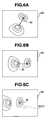
- the treatment instrument 4includes the sensor 19 adapted to detect the position and the like. Consequently, the VBS image generating unit 12 generates the VBS image A based on the line-of-sight parameter, which in turn is based on the position and the like detected by the sensor 19, and displays the VBS image A in the display unit 6. Furthermore, the image processing unit 10 causes the display unit 6 to display an image ( Fig. 5C ) resulting from a superimposition process in which the VBS image A ( Fig. 5A ) is superimposed with a graphically displayed operations guide image 30 ( Fig. 5B ) intended to direct the distal end portion to a lumen 31 into which it should be inserted. As shown in Fig.
- the graphically displayed operations guide image 30, which is displayed as an arrow, for example,is not simply an image which indicates an insertion direction. That is, direction of the arrow represents a roll angle ⁇ 1 and length of the arrow represents a bending angle ⁇ 2.
- digital informationmay be displayed in addition to the graphic display.
- the surgeoncan operate the operation portion 4B and perform a rotating operation. Then, by rotating the treatment instrument 4 by a roll angle ⁇ 1 as shown in Fig. 6B and then by bending the bending portion 4D by a bending angle ⁇ 2 as shown in Fig. 6C using the operation portion 4B, the surgeon can easily orient the distal end portion 4C to a lumen in the direction of the target site 9G.
- the surgeonrotates the bending portion 4D and the distal end portion 4C via the insertion portion 4E by griping and rotating the treatment instrument 4 on the side of a proximal end portion.
- the insertion aid apparatus 3allows the surgeon to bring the distal end portion 4C to the target site 9G by watching the VBS image A and making selection judgments at bifurcations based on the guiding information of the VBS image A. Furthermore, even if the bending portion 4D cannot be bend freely in all four directions, the insertion aid apparatus 3 allows the surgeon to operate the bending portion 4D easily based on the operation information displayed by being superimposed on the VBS image A.
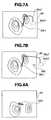
- the image processing unit 10may perform a superimposition process and thereby display an insertion route 30L1 used to insert the distal end portion 4C to the target site 9G in superimposition on the VBS image A.
- Fig. 7Ashows a case in which a transparent image 9GV1 of the target site 9G exists in a screen, where an insertion route 30L2 represented by a broken line is a non-visible insertion route which cannot be seen directly from the position of the distal end portion 4C.
- Fig. 7Bshows a case in which no transparent image 9GV1 of the target site 9G exists in the screen of the VBS image A.
- Fig. 7Balso illustrates something offscreen that is not displayed in the screen of the VBS image A.
- the insertion aid apparatus 3performs a superimposition process and thereby displays the VBS image superimposed with insertion routes, the insertion route 30L1 visible from the position of the distal end portion 4C and the non-visible insertion route 30L2, to the target site 9G from the position of the distal end portion 4C which is being inserted.
- the insertion aid apparatus 3provides excellent operability.
- the surgeoncan insert the distal end portion 4C precisely to the target site 9G in a short time. Also, since the medical apparatus 1 does not use X-rays, the patient does not get exposed to radiation.
- Fig. 6C and the likeshow an example in which the image processing unit 10 performs a superimposition process and thereby displays the VBS image A in superimposition with the transparent image 9GV1 of the target site 9G.
- the target site 9G displayed hereis located in such a position as not to be viewable using the currently set line-of-sight parameter, but displayed as the transparent image 9GV1 to provide position information about the target site 9G to the surgeon.
- the transparent image 9GV1is represented by a broken line or displayed in a distinctive color so as to be easily distinguished from viewable sites.
- information about distance from the target site 9Gcan be provided to the surgeon using graphic display.
- the image 9GV of the target site 9Gis set to be colored or hatched particularly conspicuously.
- the information of a predetermined size to be attached to the transparent image 9GV1may have a fixed size to provide intuitive information about the distance from the target site 9G to the surgeon.
- the surgeonis allowed to set a predetermined size for a target position i.e., to set the volume of the target site 9G, via the input unit 14.
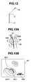
- the image processing unit 10can perform a superimposition process and thereby display the volume of the target site 9G, length of the insertion route from the current position of the distal end portion 4C to the target site 9G, and the number of bifurcations N on the insertion route in superimposition.
- Fig. 9A and 9Bwhen the volume of the target site 9G is set, the image processing unit 10 can perform a superimposition process and thereby display the volume of the target site 9G, length of the insertion route from the current position of the distal end portion 4C to the target site 9G, and the number of bifurcations N on the insertion route in superimposition.
- Fig. 9Ais an example in which operation information is displayed below the VBS image A in superimposition while Fig. 9B is an example in which operation information is displayed in the VBS image A in superimposition.
- the insertion aid apparatus described abovecan convey more information to the surgeon, and thus provides more excellent operability. That is, although three-dimensional display such as the virtual image 6B in Fig. 3 is not provided, the surgeon can obtain information about approximate distance to the target site 9G.
- the image processing unit 10may perform a superimposition process of operation information only when bending operation or rotating operation is necessary. That is, when the distal end portion 4C is passing through a non-bifurcated lumen before reaching a bifurcation or when the distal end portion 4C is oriented in a correct insertion direction, there is no need to provide operation information to the surgeon.
- the image processing unit 10performs a superimposition process for display of operation information only when the distal end portion 4C reaches a predetermined operation information display area and a predetermined bending angle threshold and a predetermined roll angle threshold are reached.
- the image processing unit 10displays operation information in superimposition only for bending operation or rotating operation whichever needs to be performed. That is, the image processing unit 10 performs a superimposition process of the operation information when at least either of bending operation and rotating operation is required.
- the image processing unit 10which displays operation information in superimposition based on the bending angle threshold and the roll angle threshold provides good operability because unnecessary information is not presented to the surgeon.
- the operation information display areais a region of the bronchi in a predetermined three-dimensional space with reference to bifurcations N1 to NX of the insertion route R1, for example, in a sphere SX of a predetermined radius from the bifurcation NX. That is, as described later, even after the distal end portion 4C passes a bifurcation, preferably operation information is displayed as long as the distal end portion 4C is located in the operation information display area. This is to display a recovery method or the like in case the distal end portion 4C is inserted into a lumen in a wrong direction due to misoperation or the like, as described later.
- the position of the distal end portion 4Cis calculated based on the position of the sensor 19.
- the radius of the sphere SX which provides the operation information display areais equal to or longer than a device tip length L, but may vary with the position of the bifurcation N, where the device tip length L is the length of the bending portion 4D used for bending operation of the distal end portion 4C.
- the image processing unit 10 of the insertion aid apparatus 3can alert the surgeon by presenting a special display, for example, by displaying an X mark such as shown in Fig. 11 in addition to the superimposed display of the insertion route.
- the position of the distal end 4Hwill be defined as point B, a fulcrum for bending of the bending portion 4D as point A, and a starting point of the bending portion 4D on the side of the proximal end portion as point O.
- the insertion aid apparatus 3calculates positions of point A, point B, and point O based on time-series data on the position of the distal end 4H stored in the position storage unit 22B.
- the image processing unit 10does not display the bending angle ⁇ 2 and the roll angle ⁇ 1 as operation information.
- the image processing unit 10does not perform a superimposition process of the bending angle ⁇ 2 or the roll angle ⁇ 1.
- information that the distal end portion 4C is oriented in the correct insertion directionmay be displayed as text information 30M.
- a vector Vis derived from a tangent to the insertion direction at a bifurcation of the insertion route, to begin with.
- a vector ABis derived from position information about point A and point B or from a distal end direction vector at point A.
- a vector OAis derived and a plane OAV perpendicular to the vector OA is defined.
- the bending angle ⁇ 2is calculated. That is, a circle centered at point A and having a radius equal to the device tip length L is created such that a point of intersection with the area in the insertion route direction on a plane OAB will be point B2. Then, as shown in Fig. 15B , an angle between the vector AB and a vector AB2 is the bending angle ⁇ 2. Consequently, as shown in Fig. 15C , the roll angle ⁇ 1 and the bending angle ⁇ 2 are displayed by being superimposed on the VBS image A.
- operating directionis displayed to inform the surgeon of rotating direction or bending direction.
- the operation informationmay be displayed either in text form as shown in Figs. 18A and 18B or in graphic form shown in Figs. 18C and 18D .
- the graphic display shown in Fig. 18(C) and the likeis superimposed on a virtual endoscopic image.
- the second function of the insertion aid apparatus 3is to aid the bending operation of the bending portion 4D of the treatment instrument 4, but the second function can also be used to aid the bending operation of the bending portion 2D of the endoscope 2A. That is, during insertion operation of the insertion portion 2E, if the distal end portion 4C of the treatment instrument 4 is inserted into the channel 2F1 in advance, the sensor 19 can be placed in a predetermined position of the insertion-portion distal end portion 2C.
- the insertion aid apparatus 3can graphically display bending operation information about the bending portion 2D in superimposition on the VBA image B to the surgeon.
- the insertion aid apparatus 3may be configured to perform a process to display the bending operation information in superimposition on a real image.
- a virtual image of the treatment instrument 4may be displayed in the display unit 6, being superimposed on a VBS image C whose line-of-sight parameter is viewable from the treatment instrument 4.
- the insertion aid apparatus 3calculates the shortest route as the insertion route.
- multiple insertion routesmay be displayed simultaneously when selected by the surgeon.
- the next shortest insertion routemay be displayed when, for example, a "2nd ROUTE" (next candidate display) button 6P presented in the display unit 6 of a touch panel type is pressed or selected by an operator.
- the "2nd ROUTE" buttonmay be a dedicated mechanical button.
- the insertion routesare displayed in different colors, line shapes, or the like.
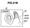
- the distal end portion 4Cis located in a lumen off the insertion route (first insertion route) due to a wrong operation, there are cases where the distal end portion 4C can reach the target site 9G through another insertion route (second insertion route). In that case, as shown in Fig. 21A , the "2nd ROUTE" button is automatically displayed in the display unit 6.
- the insertion aid apparatus described abovecalculates multiple insertion routes, allowing the surgeon to select the most suitable insertion route at the time even during an insertion operation, and thus provides good operability.
- the medical apparatus 1A according to the present embodimentis similar to the medical apparatus 1 according to the first embodiment, and the same components as those in the first embodiment are denoted by the same reference numerals as the corresponding components, and description thereof will be omitted.
- an insertion aid apparatus 3A of the medical apparatus 1Aincludes a correction unit 23 adapted to correct the position and the like detected by the sensor 19, based on a real image picked up by the CCD 2G.
- the control unit 11can cause the VBS image generating unit 12 to generate a VBS image B similar to a real image photographed by the CCD 2G. That is, based on the position, direction, and roll angle (X0, Y0, Z0, a0, e0, r0) of the sensor 19 detected by the sensor 19, first the control unit 11 generates a VBS image B whose line-of-sight parameter includes the position, direction, and roll angle (X1, Y1, Z1, a1, e1, r1) of the CCD 2G at the time. Then, the control unit 11 compares similarity between the VBS image B and the real image.
- the similarity of imagesis checked by known image processing, which may use either matching at a pixel data level or matching at the level of features extracted from the images.
- the matching process of the real image and the VBS image Bis performed per frame of the real image, and an actual comparison process is carried out with reference to similarity between a static endoscopic image and the VBS image B.
- the control unit 11If the comparison and calculation of similarity between the real image and the VBS image B reveals a larger error e between the two images than an allowable error e0 (No), the control unit 11 outputs the line-of-sight parameter whose values have been changed slightly to the VBS image generating unit 12.
- the VBS image generating unit 12generates a next VBS image B based on the new line-of-sight parameter.
- the VBS image B generated by the VBS image generating unit 12gradually becomes more similar to the real image, and after a few iterations, the error e between the two images becomes smaller than the allowable error e0.
- the control unit 11detects the line-of-sight parameter of the CCD 2G, in other words, the position, direction, and roll angle (Xn, Yn, Zn, an, en, rn) of the CCD 2G, equal to or smaller than the allowable error e0 in real image information.
- the correction unit 23uses the line-of-sight parameter to correct the position, direction, and roll angle (X0, Y0, Z0, a0, e0, r0) of the sensor 19 detected by the sensor 19, based on the position, direction, and roll angle (Xn, Yn, Zn, an, en, rn) of the CCD 2G.
- control unit 11calibrates the sensor 19 based on a second virtual endoscopic image B and the real image, where the second virtual endoscopic image B has the line-of-sight parameter which is made up of the position, the direction, and the roll angle of the CCD 2G.
- the surgeonhas a clearer view of a relative relationship between the distal end 4H of the treatment instrument 4 and the target site 9G.
- the position of the target site 9Ghas been set by the input unit 14 in a CT coordinate system which is based on three-dimensional image data.
- the position of the sensor 19is obtained in a sensor coordinate system relative to, for example, the magnetic field generating antenna 20.
- a correction process performed by the correction unit 23is intended not only to correct detection errors of the sensor 19, but also to ensure consistency between the CT coordinate system and the sensor coordinate system, in other words, calculate a coordinate transformation formula between the different coordinate systems.
- the coordinate transformation formula calculated by the correction unit 23allows the control unit 11 to perform control more accurately and easily.
- the medical apparatus 1Afeatures higher processing speed and enables highly accurate navigation, and thus allows the distal end portion 4C of the treatment instrument 4 to be inserted to the target site 9G in a lumen more reliably.
- the medical apparatus 1B according to the present variationis similar to the medical apparatus 1A according to the second embodiment, and the same components as those in the second embodiment are denoted by the same reference numerals as the corresponding components, and description thereof will be omitted.
- a correction unit 23B of an insertion aid apparatus 3B of the medical apparatus 1Bincludes a correction unit 23B adapted to correct the position and the like detected by the sensor 19, based on an image of the treatment instrument 4 contained in a real image picked up by the CCD 12 of the endoscope 2A.
- the surgeonprotrudes the distal end portion 4C of the treatment instrument 4 from the treatment instrument outlet 2F of the insertion-portion distal end portion 2C.
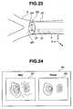
- Thisprovides a real image which shows the distal end portion 4C being picked up, as shown in Fig. 26 .
- the treatment instrument 4has a graduated scale 4L which allows an amount of protrusion and the like to be detected and a graduated scale 4M which allows rotation to be detected.
- the graduated scalescan be read from the real image by the control unit 11. Based on the read data and the like, the control unit 11 can calculates a relative positional relationship between the distal end 4H of the treatment instrument 4 and the CCD 2G.
- the control unit 11corrects the information detected by the sensor 19 to improve accuracy of the information, and in other words, calibrates the information from the sensor 19.
- the medical apparatus 1Benables more accurate navigation, and thus allows the distal end portion 4C of the treatment instrument 4 to be inserted to the target site 9G in a lumen more reliably.
- a medical apparatus 1C according to a third embodimentis similar to the medical apparatus 1 according to the first embodiment, and the same components as those in the first embodiment are denoted by the same reference numerals as the corresponding components, and description thereof will be omitted.
- the medical apparatus 1Cincludes a treatment instrument 4 inserted alone into the bronchus 9 of the patient and a reference marker 24 placed on a body surface of the patient 7.
- the medical apparatus 1Ccan ensure consistency between the CT coordinate system and the sensor coordinate system, and in other words, calculate a coordinate transformation formula between the different coordinate systems.
- the treatment instrument 4cannot acquire endoscopic images of bifurcations during insertion operation.
- the surgeoncan insert the distal end portion 4C to the target site 9G based on the VBS image A and operations guide image 30 displayed by an insertion aid apparatus 3C of the medical apparatus 1C.
- Movements of the insertion aid apparatus 3 of the medical apparatus 1Care the same as movements carried out to aid the treatment instrument 4 in the medical apparatus 1.
- the medical apparatus 1C according to the present embodimentprovides the same advantages as the medical apparatus 1 according to the first embodiment.
- the medical apparatusincludes: a treatment instrument inserted in a channel of an endoscope so as to protrude from an endoscopic distal end portion, equipped with a sensor and a bending portion in a distal end portion, and inserted to a target site in a bronchus, where the sensor is intended to detect a position, a direction, and a roll angle; an image data storing unit adapted to store three-dimensional image data of the bronchus acquired in advance; an input unit used to set the target site; a virtual endoscopic image generating unit adapted to generate a virtual endoscopic image using a line-of-sight parameter which includes the position, the direction, and the roll angle of the distal end portion detected by the sensor, based on the three-dimensional image data; an image processing unit adapted to perform a superimposition process and thereby display bending operation information of the bending portion, rotating operation information of the distal end portion, the virtual endoscopic image, and an insertion route in superimposition with one another to help
- the present inventionis not limited to the above described embodiments, and various modifications, changes and the like can be made within a range where the gist of the present invention is not changed.
Landscapes
- Health & Medical Sciences (AREA)
- Life Sciences & Earth Sciences (AREA)
- Surgery (AREA)
- Engineering & Computer Science (AREA)
- General Health & Medical Sciences (AREA)
- Veterinary Medicine (AREA)
- Public Health (AREA)
- Animal Behavior & Ethology (AREA)
- Nuclear Medicine, Radiotherapy & Molecular Imaging (AREA)
- Molecular Biology (AREA)
- Biomedical Technology (AREA)
- Heart & Thoracic Surgery (AREA)
- Medical Informatics (AREA)
- Biophysics (AREA)
- Radiology & Medical Imaging (AREA)
- Physics & Mathematics (AREA)
- Pathology (AREA)
- Optics & Photonics (AREA)
- Pulmonology (AREA)
- Otolaryngology (AREA)
- Physiology (AREA)
- Robotics (AREA)
- Endoscopes (AREA)
Abstract
Description
- The present invention relates to a medical apparatus equipped with a treatment instrument to be inserted into a lumen of a subject to carry out treatment, and more particularly to a medical apparatus which aids a treatment instrument insertion operation using virtual endoscopic images based on three-dimensional image data of the lumen.
- In recent years, diagnosis and treatment have come to be carried out widely using three-dimensional image data. For example, three-dimensional images inside a subject are obtained by picking up tomograms of the subject using an X-ray CT (Computed Tomography) apparatus and used to carry out diagnosis and the like of a target site.
- The CT apparatus performs successive scans (helical scans) of the subject continually while rotating X-ray irradiation position and detection position continuously by moving the subject. Then, three-dimensional image data is obtained from a large number of successive two-dimensional tomograms of the subject.
- Examples of the three-dimensional image data used for diagnosis and treatment include three-dimensional image data of the bronchi of the lungs. The three-dimensional image data of the bronchi of the lungs is used, for example, to three-dimensionally locate an abnormal site where lung cancer is suspected. Then, to check the abnormal site by a biopsy, an endoscope is inserted into the bronchi, a treatment instrument such as a biopsy needle or biopsy forceps is protruded from a distal end portion of the endoscope, and a sample is taken from the target site.
- In a lumen having a plurality of bifurcations, such as a bronchus, it is sometimes not easy to insert a treatment instrument precisely into a target site in the lung in a short time. Thus, for example, Patent Application Laid-Open Publication No.
2009-56238 - Also, to assist insertion operation, Patent Application Laid-Open Publication No.
2002-119507 discloses a medical apparatus which displays a virtual image viewed from a distal end portion of a catheter inserted in a subject while Patent Application Laid-Open Publication No.2002-306403 discloses an endoscope apparatus which displays a virtual image of a distal end portion of an endoscope in superimposition on a virtual endoscopic image. - Here, in order to insert the distal end portion to the target site, an operation of the bending portion to bend the distal end portion is essential, but there has been sometime a case where such operation is not easy.
- Further, in a peripheral lumen having a small diameter into which an endoscope provided with a CCD can not be inserted, it has been necessary to confirm the position of the distal end portion of the treatment instrument in the lumen by X-ray transillumination.
- An object of the present invention is to provide a medical apparatus allowing a distal end of a treatment instrument to be inserted to a target site in a lumen.
- According to one aspect of the present invention, there is provided a medical apparatus comprising: treatment means provided with a distal end portion, a sensor disposed in the distal end portion and configured to detect a position, a direction and a roll angle, and a bending portion adapted to bend the distal end portion, the distal end portion of the treatment means being allowed to be inserted to a target position in a lumen of a subject; storage means adapted to store three-dimensional image data of the lumen acquired in advance; target position setting means adapted to set the target position based on the three-dimensional image data; virtual endoscopic image generating means adapted to generate a virtual endoscopic image using a line-of-sight parameter which includes the position, the direction, and the roll angle of the distal end portion detected by the sensor, based on the three-dimensional image data; and image processing means adapted to perform a superimposition process and thereby display operation information used to insert the distal end portion to the predetermined position in superimposition on the virtual endoscopic image.
Fig. 1 is a schematic diagram for illustrating insertion of an endoscope into a bronchus using a medical apparatus according to a first embodiment;Fig. 2 is a configuration diagram for illustrating a configuration of the medical apparatus according to the first embodiment;Fig. 3 is a diagram showing an example of a display screen of the medical apparatus according to the first embodiment;Fig. 4 is a diagram showing an example of the display screen of the medical apparatus according to the first embodiment;Fig. 5A is a diagram for illustrating a configuration of the display screen of the medical apparatus according to the first embodiment;Fig. 5B is a diagram for illustrating the configuration of the display screen of the medical apparatus according to the first embodiment;Fig. 5C is a diagram for illustrating the configuration of the display screen of the medical apparatus according to the first embodiment;Fig. 6A is a diagram showing an example of the display screen of the medical apparatus according to the first embodiment;Fig. 6B is a diagram showing an example of the display screen of the medical apparatus according to the first embodiment;Fig. 6C is a diagram showing an example of the display screen of the medical apparatus according to the first embodiment;Fig. 7A is a diagram showing an example of the display screen of the medical apparatus according to the first embodiment;Fig. 7B is a diagram showing an example of the display screen of the medical apparatus according to the first embodiment;Fig. 8A is a diagram showing an example of the display screen of the medical apparatus according to the first embodiment;Fig. 8B is a diagram showing an example of the display screen of the medical apparatus according to the first embodiment;Fig. 8C is a diagram showing an example of the display screen of the medical apparatus according to the first embodiment;Fig. 9A is a diagram showing an example of the display screen of the medical apparatus according to the first embodiment;Fig. 9B is a diagram showing an example of the display screen of the medical apparatus according to the first embodiment;Fig. 10A is an explanatory diagram for illustrating an insertion route of the medical apparatus according to the first embodiment;Fig. 10B is an explanatory diagram for illustrating an insertion route of the medical apparatus according to the first embodiment;Fig. 11 is a diagram showing an example of the display screen of the medical apparatus according to the first embodiment;Fig. 12 is a diagram showing vectors of a bending portion of the medical apparatus according to the first embodiment;Fig. 13A is a diagram showing an example of movement and the display screen of the medical apparatus according to the first embodiment;Fig. 13B is a diagram showing an example of the movement and display screen of the medical apparatus according to the first embodiment;Fig. 14A is a diagram showing an example of movement, operation angle calculation, and the display screen of the medical apparatus according to the first embodiment;Fig. 14B is a diagram showing an example of the movement, operation angle calculation, and display screen of the medical apparatus according to the first embodiment;Fig. 14C is a diagram showing an example of the movement, operation angle calculation, and display screen of the medical apparatus according to the first embodiment;Fig. 15A is a diagram showing an example of the movement, operation angle calculation, and display screen of the medical apparatus according to the first embodiment;Fig. 15B is a diagram showing an example of the movement, operation angle calculation, and display screen of the medical apparatus according to the first embodiment;Fig. 15C is a diagram showing an example of the movement, operation angle calculation, and display screen of the medical apparatus according to the first embodiment;Fig. 16 is a diagram showing an example of manipulations of the medical apparatus according to the first embodiment;Fig. 17 is a diagram showing an example of manipulations of the medical apparatus according to the first embodiment;Fig. 18A is a diagram showing an example of the display of operation information about the medical apparatus according to the first embodiment;Fig. 18B is a diagram showing an example of the display of operation information about the medical apparatus according to the first embodiment;Fig. 18C is a diagram showing an example of the display of operation information about the medical apparatus according to the first embodiment;Fig. 18D is a diagram showing an example of the display of operation information about the medical apparatus according to the first embodiment;Fig. 19A is an explanatory diagram for illustrating an insertion route of the medical apparatus according to the first embodiment;Fig. 19B is an explanatory diagram for illustrating an insertion route of the medical apparatus according to the first embodiment;Fig. 20A is a diagram showing an example of the display screen of the medical apparatus according to the first embodiment;Fig. 20B is a diagram showing an example of the display screen of the medical apparatus according to the first embodiment;Fig. 21A is a diagram showing an example of the display screen of the medical apparatus according to the first embodiment;Fig. 21B is a diagram showing an example of the display screen of the medical apparatus according to the first embodiment;Fig. 22 is a configuration diagram for illustrating a configuration of a medical apparatus according to a second embodiment;Fig. 23 is a schematic diagram for illustrating a correction method of the medical apparatus according to the second embodiment;Fig. 24 is a diagram showing an example of a display screen of the medical apparatus according to the second embodiment;Fig. 25 is a schematic diagram for illustrating a correction method of a medical apparatus according to a variation of the second embodiment;Fig. 26 is a diagram showing an example of a display screen of the medical apparatus according to the variation of the second embodiment; andFig. 27 is a configuration diagram for illustrating a configuration of a medical apparatus according to a third embodiment.- A
medical apparatus 1 according to a first embodiment of the present invention will be described below with reference to the drawings.Fig. 1 is a schematic diagram showing how atarget site 9G at a bronchial end is biopsied by passing aninsertion portion 4E of atreatment instrument 4 through a channel 2F1 of anendoscope 2A of anendoscope apparatus 2 inserted into abronchus 9 of apatient 7. - As shown in
Fig. 1 , thebronchi 9 have multiple bifurcations. Therefore, to insert thetreatment instrument 4 to thetarget site 9G, a surgeon needs to make a correct selection judgment and perform a proper insertion operation at each bifurcation based on an endoscopic image picked up by aCCD 2G (seeFig. 2 ) which is image pickup means in an insertion-portiondistal end portion 2C of theendoscope 2A. Incidentally, a CMOS or the like may be used as the image pickup means. - As shown in
Fig. 2 , in addition to theendoscope apparatus 2 and thetreatment instrument 4, themedical apparatus 1 includes aninsertion aid apparatus 3 adapted to aid the surgeon in making judgments and performing operations. That is, a first function of theinsertion aid apparatus 3 is to help the surgeon make selection judgments at bifurcations. A second function of theinsertion aid apparatus 3 is to help the surgeon perform bending operation. - The
endoscope apparatus 2 includes the insertion-portiondistal end portion 2C, a bendingportion 2D used for bending operation of the insertion-portiondistal end portion 2C, aninsertion portion 2E elongated in shape, and anoperation portion 2B (seeFig. 2 ), which are installed consecutively. Meanwhile, thetreatment instrument 4 serving as treatment means includes adistal end portion 4C, a bendingportion 4D used for bending operation of thedistal end portion 4C, aninsertion portion 4E elongated in shape, and anoperation portion 4B (seeFig. 2 ), which are installed consecutively. - As shown in
Fig. 2 , theinsertion aid apparatus 3 includes a CT imagedata storing unit 13, aninput unit 14, a virtual endoscopicimage generating unit 12 serving as virtual endoscopic image generating means (hereinafter the virtual endoscopic image will also be referred to as a "VBS image" which stands for Virtual Bronchus Scope image), animage processing unit 10, adisplay unit 6, asensor 19 disposed in thedistal end portion 4C of thetreatment instrument 4, a magneticfield generating antenna 20, anantenna drive unit 21, aposition detecting unit 22, aposition storage unit 22B, and acontrol unit 11 which performs overall control. Incidentally, the components of theinsertion aid apparatus 3 may be common with components (not shown) of theendoscope apparatus 2 which perform various processes. - The CT image
data storing unit 13 serving as storage means is a semiconductor storage device, a magnetic recording device, or the like which stores three-dimensional image data, for example, in DICOM (Digital Imaging and Communication in Medicine) format by receiving the three-dimensional image data via a receiving unit (not shown) as the three-dimensional image data is generated by a known CT apparatus (not shown) which picks up X-ray tomograms of thepatient 7. - The
input unit 14 includes a keyboard, a mouse, and the like used by the surgeon to input information to themedical apparatus 1. In setting the position of thetarget site 9G based on three-dimensional image data, the surgeon also uses theinput unit 14 serving as target position setting means. - The VBS
image generating unit 12 generates VBS images from the three-dimensional image data in DICOM format based on a six-dimensional line-of-sight parameter described later. - The
image processing unit 10 serving as image processing means performs image processing on endoscopic images (hereinafter also referred to as "real images") picked up by theCCD 2G as well as performs processing to display operation information, rotating operation information about the bendingportion 4D, and a VBS image in superimposition as described later, where the operation information, the rotating operation information, and the VBS image are used to help insert thedistal end portion 4C to thetarget site 9G. Thedisplay unit 6 serves as display means which displays real images, VBS images, and the like. - As described earlier, the
treatment instrument 4 has thesensor 19 in thedistal end portion 4C to detect a position, a direction, and a roll angle (hereinafter also referred to as the "position and the like"). Thesensor 19 is, for example, a magnetic field detection sensor and is adapted to detect a magnetic field generated by the magneticfield generating antenna 20 made up of three antennas disposed outside thepatient 7 and thereby detect position and the like where thetreatment instrument 4 is disposed. Alternatively, an MR sensor, a Hall element, a coil, or the like may be used as the magnetic field detection sensor. - For example, ac magnetic fields of different frequencies are generated from multiple antennas of the magnetic
field generating antenna 20 by theantenna drive unit 21. Thesensor 19 detects the multiple ac magnetic fields of different frequencies in distinction from one another, allowing theposition detecting unit 22 to detect information about the position, direction, and roll angle (X, Y, Z, a, e, r) of thesensor 19 with respect to the magneticfield generating antenna 20 based on information from thesensor 19, where (X, Y, Z) are three-dimensional coordinate values, (a) is an azimuth angle, (e) is an elevation angle, and (r) is a roll angle. Since the position of disposition of thesensor 19 in thedistal end portion 4C is known, a predetermined location of thetreatment instrument 4, e.g., position of adistal end 4H is calculated based on the position of thesensor 19. Theposition storage unit 22B time-sequentially stores the position of thedistal end 4H and the like detected by theposition detecting unit 22. - Next, a method for insertion operation aid in the
medical apparatus 1 will be described. As shown inFig. 3 , when theinsertion aid apparatus 3 performs insertion navigation, first adisplay screen 6a of thedisplay unit 6 displaysinformation 6A including information about thepatient 7 and information about bifurcations of thebronchi 9, avirtual image 6B of thebronchi 9 based on three-dimensional image data, and a VBS image B (6C) and the like whose details are not illustrated. The VBS image B is a VBS image based on the line-of-sight parameter of theCCD 2G. The line-of-sight parameter is a six-dimensional parameter which includes the position, direction, and roll angle (X, Y, Z, a, e, r). Incidentally, as described later, a VBS image A is a VBS image based on the line-of-sight parameter of thedistal end portion 4C of thetreatment instrument 4. - By operating the
input unit 14, the surgeon setstarget site 9G of the lungs, which is a target position, with apointer 14A or the like using thevirtual image 6B. Incidentally, the surgeon may set any site such as a passing point along the way rather than thetarget site 9G. Once thetarget site 9G or the like is set, theinsertion aid apparatus 3 calculates an insertion route R1, and displays the insertion route R1 in superimposition on thevirtual image 6B as shown inFig. 3 . The insertion route R1 is a core line leading to thetarget site 9G out of core lines which link center-of-gravity points or center points of lumen cross sections of the virtual endoscopic images. - Then, the VBS
image generating unit 12 creates a VBS image B for each of the multiple bifurcations along the insertion route R1. Incidentally, theinsertion aid apparatus 3 may have a VBS image storage unit (not shown) adapted to store VBS images of thebronchi 9 generated beforehand by the VBSimage generating unit 12, and may display VBS images of the bifurcations along the insertion route R1 by extracting them from the stored VBS images. - Then, once an insertion operation is started, as shown in
Fig. 4 , thedisplay screen 6a displays areal image 6F picked up by theCCD 2G and processed by theimage processing unit 10, multiple thumbnail VBS images (6E) which are reduced VBS images of the bifurcations appearing in the course of the insertion operation, and a VBS image B (6D) of the bifurcation which will appear next. The VBS image B (6D) is superimposed with guidinginformation 6G indicating which of the lumens located ahead of the bifurcation to insert the distal end portion into. By performing the insertion operation while making selection judgments based on the guidinginformation 6G of theinsertion aid apparatus 3, the surgeon can insert the insertion-portiondistal end portion 2C to near thetarget site 9G. So doing, thetreatment instrument 4 does not need to be passed through thechannel 2Finsertion portion 2E. Alternatively, thetreatment instrument 4 may be passed through the channel 2F1 of theinsertion portion 2E with thedistal end portion 4C fixed to a predetermined position of the insertion-portiondistal end portion 2C of theinsertion portion 2E. - If the
target site 9G is at an ending of thebronchus 9, the surgeon cannot insert the insertion-portiondistal end portion 2C of theendoscope 2A to thetarget site 9G even if theinsertion portion 2E of theendoscope 2A has a thin diameter. Thus, next the surgeon has to insert thedistal end portion 4C of thetreatment instrument 4 into thetarget site 9G in a deeper part by protruding thetreatment instrument 4 from atreatment instrument outlet 2F of the insertion-portiondistal end portion 2C of theendoscope 2A and carry out predetermined treatment there. - That is, in order to be able to be inserted into a thin lumen, the
insertion portion 2E of theendoscope 2A has a diameter of, for example, 3 mm, which is smaller than a gastrointestinal endoscope or the like, but thetreatment instrument 4 has a diameter of, for example, 1 mm so as to be able to be inserted into a still thinner peripheral lumen. Therefore, the bendingportion 4D of thetreatment instrument 4 is bendable only either in an up/down direction or a left/right direction. That is, unlike gastrointestinal endoscopes, the bendingportion 4D cannot be bend freely in all four directions: left, right, up, and down. Consequently, the bending operation of the bendingportion 4D requires skills. Incidentally, although the phrase "up/down direction or left/right direction" is used for the sake of convenience, the phrase means one direction in a plane orthogonal to an insertion direction. - Furthermore, in a thin-diameter lumen into which the
insertion portion 2E of theendoscope 2A cannot be inserted, the surgeon cannot view bifurcations using real images from theCCD 2G. - However, the VBS
image generating unit 12 of theinsertion aid apparatus 3 generates the VBS image A based on the line-of-sight parameter of thedistal end portion 4C, more precisely, part of thedistal end portion 4C, for example, thedistal end 4H, of thetreatment instrument 4. - That is, as described earlier, the
treatment instrument 4 includes thesensor 19 adapted to detect the position and the like. Consequently, the VBSimage generating unit 12 generates the VBS image A based on the line-of-sight parameter, which in turn is based on the position and the like detected by thesensor 19, and displays the VBS image A in thedisplay unit 6. Furthermore, theimage processing unit 10 causes thedisplay unit 6 to display an image (Fig. 5C ) resulting from a superimposition process in which the VBS image A (Fig. 5A ) is superimposed with a graphically displayed operations guide image 30 (Fig. 5B ) intended to direct the distal end portion to alumen 31 into which it should be inserted. As shown inFig. 5B , the graphically displayed operations guideimage 30, which is displayed as an arrow, for example, is not simply an image which indicates an insertion direction. That is, direction of the arrow represents a roll angle θ1 and length of the arrow represents a bending angle θ2. Incidentally, digital information may be displayed in addition to the graphic display. - As shown in
Fig. 6A , by watching the VBS image A superimposed with the intuitively understandable graphically displayed operations guideimage 30 instead of numerals, the surgeon can operate theoperation portion 4B and perform a rotating operation. Then, by rotating thetreatment instrument 4 by a roll angle θ1 as shown inFig. 6B and then by bending the bendingportion 4D by a bending angle θ2 as shown inFig. 6C using theoperation portion 4B, the surgeon can easily orient thedistal end portion 4C to a lumen in the direction of thetarget site 9G. Incidentally, in the rotating operation, the surgeon rotates the bendingportion 4D and thedistal end portion 4C via theinsertion portion 4E by griping and rotating thetreatment instrument 4 on the side of a proximal end portion. - That is, even if the
treatment instrument 4 is not equipped with aCCD 2G, theinsertion aid apparatus 3 allows the surgeon to bring thedistal end portion 4C to thetarget site 9G by watching the VBS image A and making selection judgments at bifurcations based on the guiding information of the VBS image A. Furthermore, even if the bendingportion 4D cannot be bend freely in all four directions, theinsertion aid apparatus 3 allows the surgeon to operate the bendingportion 4D easily based on the operation information displayed by being superimposed on the VBS image A. - The
image processing unit 10 may perform a superimposition process and thereby display an insertion route 30L1 used to insert thedistal end portion 4C to thetarget site 9G in superimposition on the VBS image A.Fig. 7A shows a case in which a transparent image 9GV1 of thetarget site 9G exists in a screen, where an insertion route 30L2 represented by a broken line is a non-visible insertion route which cannot be seen directly from the position of thedistal end portion 4C. On the other hand,Fig. 7B shows a case in which no transparent image 9GV1 of thetarget site 9G exists in the screen of the VBS image A. However, anarrow 30D indicates the direction in which thetarget site 9G exists, allowing the surgeon to recognize the direction in which thetarget site 9G exists. Incidentally, for the sake of explanation,Fig. 7B also illustrates something offscreen that is not displayed in the screen of the VBS image A. - Regarding operation information on the bending
portion 4D, theinsertion aid apparatus 3 performs a superimposition process and thereby displays the VBS image superimposed with insertion routes, the insertion route 30L1 visible from the position of thedistal end portion 4C and the non-visible insertion route 30L2, to thetarget site 9G from the position of thedistal end portion 4C which is being inserted. Thus, being capable of conveying to the surgeon not only the nearest operation information, but also information about subsequent insertion operations, theinsertion aid apparatus 3 provides excellent operability. - As described above, with the
medical apparatus 1, by performing insertion operation while operating the bendingportion 4D according to the operation information displayed in thedisplay unit 6 of theinsertion aid apparatus 3, the surgeon can insert thedistal end portion 4C precisely to thetarget site 9G in a short time. Also, since themedical apparatus 1 does not use X-rays, the patient does not get exposed to radiation. - Incidentally,
Fig. 6C and the like show an example in which theimage processing unit 10 performs a superimposition process and thereby displays the VBS image A in superimposition with the transparent image 9GV1 of thetarget site 9G. Thetarget site 9G displayed here is located in such a position as not to be viewable using the currently set line-of-sight parameter, but displayed as the transparent image 9GV1 to provide position information about thetarget site 9G to the surgeon. When displayed, preferably the transparent image 9GV1 is represented by a broken line or displayed in a distinctive color so as to be easily distinguished from viewable sites. Furthermore, by attaching information of a predetermined size to the transparent image 9GV1, information about distance from thetarget site 9G can be provided to the surgeon using graphic display. - For example, after the
distal end 4H is inserted to a position where thetarget site 9G can be processed, i.e., where thetarget site 9G is viewable as shown inFig. 8A , when thedistal end 4H further approaches thetarget site 9G as shown inFig. 8B , size of an image 9GV of thetarget site 9G in the VBS image A becomes larger. Then as shown inFig. 8C , when thedistal end portion 4C abuts thetarget site 9G, the entire VBS image A turns into the image 9GV of thetarget site 9G. In so doing, to distinguish thetarget site 9G displayed in thedisplay unit 6 from any other luminal wall abutted by thedistal end portion 4C, preferably the image 9GV of thetarget site 9G is set to be colored or hatched particularly conspicuously. - The information of a predetermined size to be attached to the transparent image 9GV1 may have a fixed size to provide intuitive information about the distance from the
target site 9G to the surgeon. Preferably, however, the surgeon is allowed to set a predetermined size for a target position i.e., to set the volume of thetarget site 9G, via theinput unit 14. As shown inFigs. 9A and9B , when the volume of thetarget site 9G is set, theimage processing unit 10 can perform a superimposition process and thereby display the volume of thetarget site 9G, length of the insertion route from the current position of thedistal end portion 4C to thetarget site 9G, and the number of bifurcations N on the insertion route in superimposition. Incidentally,Fig. 9A is an example in which operation information is displayed below the VBS image A in superimposition whileFig. 9B is an example in which operation information is displayed in the VBS image A in superimposition. The insertion aid apparatus described above can convey more information to the surgeon, and thus provides more excellent operability. That is, although three-dimensional display such as thevirtual image 6B inFig. 3 is not provided, the surgeon can obtain information about approximate distance to thetarget site 9G. - Incidentally, the
image processing unit 10 may perform a superimposition process of operation information only when bending operation or rotating operation is necessary. That is, when thedistal end portion 4C is passing through a non-bifurcated lumen before reaching a bifurcation or when thedistal end portion 4C is oriented in a correct insertion direction, there is no need to provide operation information to the surgeon. Thus, preferably theimage processing unit 10 performs a superimposition process for display of operation information only when thedistal end portion 4C reaches a predetermined operation information display area and a predetermined bending angle threshold and a predetermined roll angle threshold are reached. - Also, preferably the
image processing unit 10 displays operation information in superimposition only for bending operation or rotating operation whichever needs to be performed. That is, theimage processing unit 10 performs a superimposition process of the operation information when at least either of bending operation and rotating operation is required. - The
image processing unit 10 which displays operation information in superimposition based on the bending angle threshold and the roll angle threshold provides good operability because unnecessary information is not presented to the surgeon. - As shown in
Figs. 10A and10B , the operation information display area is a region of the bronchi in a predetermined three-dimensional space with reference to bifurcations N1 to NX of the insertion route R1, for example, in a sphere SX of a predetermined radius from the bifurcation NX. That is, as described later, even after thedistal end portion 4C passes a bifurcation, preferably operation information is displayed as long as thedistal end portion 4C is located in the operation information display area. This is to display a recovery method or the like in case thedistal end portion 4C is inserted into a lumen in a wrong direction due to misoperation or the like, as described later. As described earlier, the position of thedistal end portion 4C is calculated based on the position of thesensor 19. Preferably the radius of the sphere SX which provides the operation information display area is equal to or longer than a device tip length L, but may vary with the position of the bifurcation N, where the device tip length L is the length of the bendingportion 4D used for bending operation of thedistal end portion 4C. - That is, when the
distal end portion 4C is located in a lumen off the insertion route due to a wrong operation, the surgeon needs to pull back thedistal end portion 4C toward the side of the proximal end portion. In such a case, theimage processing unit 10 of theinsertion aid apparatus 3 can alert the surgeon by presenting a special display, for example, by displaying an X mark such as shown inFig. 11 in addition to the superimposed display of the insertion route. - Next, a brief description will be given of a method used by the
control unit 11 to calculate the bending angle θ2 and roll angle θ1 which are pieces of operation information. - Hereinafter, as shown in
Fig. 12 , the position of thedistal end 4H will be defined as point B, a fulcrum for bending of the bendingportion 4D as point A, and a starting point of the bendingportion 4D on the side of the proximal end portion as point O. Theinsertion aid apparatus 3 calculates positions of point A, point B, and point O based on time-series data on the position of thedistal end 4H stored in theposition storage unit 22B. - As shown in
Fig. 13A , when point B exists in the operation information display area of the bifurcation NX, i.e., in an area SXA of the sphere SX on the side of the insertion route direction, if thedistal end portion 4C is kept moving forward, i.e., if thedistal end portion 4C is pushed in, thedistal end portion 4C can be advanced to a lumen located in the direction along the insertion route R1. Thus, theimage processing unit 10 does not display the bending angle θ2 and the roll angle θ1 as operation information. That is, as described earlier, when the bending angle θ2 or the roll angle θ1 is not higher than its predetermined threshold, theimage processing unit 10 does not perform a superimposition process of the bending angle θ2 or the roll angle θ1. Incidentally, as shown inFig. 13B , information that thedistal end portion 4C is oriented in the correct insertion direction may be displayed astext information 30M. - On the other hand, as shown in
Fig. 14A , when thedistal end 4H (point B) does not exist in the area SXA on the side of the insertion route direction (exists in an area XSB), thedistal end portion 4C will advance to a wrong lumen rather than the insertion route R1 if kept moving forward. In this case, the roll angle θ1 is calculated first. That is, a vector V is derived from a tangent to the insertion direction at a bifurcation of the insertion route, to begin with. Next, a vector AB is derived from position information about point A and point B or from a distal end direction vector at point A. Then, a vector OA is derived and a plane OAV perpendicular to the vector OA is defined. An angle between the vector V and the vector AB which use the vector OA as a reference point, i.e., an angle between the vector V and vector AB projected onto the plane OAV, is the roll angle θ1 as shown inFig. 14B . - If the
distal end 4H (point B) moves to the area on the side of the insertion route direction when the surgeon manipulates the roll angle θ1, there is no need to calculate the bending angle θ2. Consequently, only the roll angle θ1 is displayed in superimposition as shown inFig. 14C . - On the other hand, as shown in
Fig. 15A , if thedistal end 4H (point B) does not move to the area on the side of the insertion route direction when the roll angle θ1 is manipulated, the bending angle θ2 is calculated. That is, a circle centered at point A and having a radius equal to the device tip length L is created such that a point of intersection with the area in the insertion route direction on a plane OAB will be point B2. Then, as shown inFig. 15B , an angle between the vector AB and a vector AB2 is the bending angle θ2. Consequently, as shown inFig. 15C , the roll angle θ1 and the bending angle θ2 are displayed by being superimposed on the VBS image A. - Incidentally, depending on the
endoscope 2A or thetreatment instrument 4, there are cases in which manipulations of theoperation portion 4B on the side of the proximal end portion do not correspond directly to movements of thedistal end portion 4C. For example, as shown inFig. 16 , when a rotating portion 4B2 of theoperation portion 4B is rotated 360 degrees, thedistal end portion 4C might rotate 180 degrees. In such a case, a roll angle θ1 of the rotating portion 4B2 is calculated from the roll angle θ1 of thedistal end portion 4C using the calculation formula Θ1 = f(θ1). The calculation formula is given, for example, by Θ1 = 2 × θ1. Similarly, a bending angle θ2 of theoperation portion 4B is calculated from the bending angle θ2 of the distal end portion using a calculation formula. - Also, as shown in
Fig. 17 , when the surgeon moves a lever portion 4B2 of theoperation portion 4B forward or backward, thedistal end portion 4C might rotate or the bending portion might bend. In such a case, an amount of movement of the lever portion 4B2 is calculated from the roll angle θ1 of thedistal end portion 4C using the calculation formula Θ1 = fl(θ1). For example, if thedistal end portion 4C rotates 10 degrees when the lever portion 4B2 is moved 5 mm, the calculation formula used is ΘL = (θ2) / 2(mm). Thus, in this case, operation information about the bending angle or the roll angle is displayed in terms of an amount of lever operation, which is a physical quantity suitable for operation of the surgeon, rather than in degrees. - Furthermore, operating direction is displayed to inform the surgeon of rotating direction or bending direction. The operation information may be displayed either in text form as shown in
Figs. 18A and 18B or in graphic form shown inFigs. 18C and 18D . The graphic display shown inFig. 18(C) and the like is superimposed on a virtual endoscopic image. - In the example described above, the second function of the
insertion aid apparatus 3 is to aid the bending operation of the bendingportion 4D of thetreatment instrument 4, but the second function can also be used to aid the bending operation of the bendingportion 2D of theendoscope 2A. That is, during insertion operation of theinsertion portion 2E, if thedistal end portion 4C of thetreatment instrument 4 is inserted into the channel 2F1 in advance, thesensor 19 can be placed in a predetermined position of the insertion-portiondistal end portion 2C. - Consequently, even if the bending
portion 2D of theendoscope 2A can be bended to any one of the up/down direction and left/right direction, theinsertion aid apparatus 3 can graphically display bending operation information about the bendingportion 2D in superimposition on the VBA image B to the surgeon. Incidentally, theinsertion aid apparatus 3 may be configured to perform a process to display the bending operation information in superimposition on a real image. - Also, a virtual image of the
treatment instrument 4 may be displayed in thedisplay unit 6, being superimposed on a VBS image C whose line-of-sight parameter is viewable from thetreatment instrument 4. - Incidentally, if, for example, there is a
target site 9G of a relatively large volume at an ending of the bronchus as shown inFig. 19A , there might be multiple insertion routes R1A, R1B, and R1C as shown inFig. 19B . Basically, theinsertion aid apparatus 3 calculates the shortest route as the insertion route. - However, as shown in
Fig. 20A , multiple insertion routes may be displayed simultaneously when selected by the surgeon. Alternatively, as shown inFig. 20B , by displaying the shortest insertion route first, the next shortest insertion route may be displayed when, for example, a "2nd ROUTE" (next candidate display)button 6P presented in thedisplay unit 6 of a touch panel type is pressed or selected by an operator. Of course, the "2nd ROUTE" button may be a dedicated mechanical button. On the other hand, when multiple insertion routes are displayed simultaneously, preferably the insertion routes are displayed in different colors, line shapes, or the like. - As described with reference to
Fig. 11 , even if thedistal end portion 4C is located in a lumen off the insertion route (first insertion route) due to a wrong operation, there are cases where thedistal end portion 4C can reach thetarget site 9G through another insertion route (second insertion route). In that case, as shown inFig. 21A , the "2nd ROUTE" button is automatically displayed in thedisplay unit 6. - As shown in
Fig. 21B , when the surgeon presses the "2nd ROUTE" button, the second insertion route is displayed, allowing the surgeon to continue the insertion operation. - The insertion aid apparatus described above calculates multiple insertion routes, allowing the surgeon to select the most suitable insertion route at the time even during an insertion operation, and thus provides good operability.
- Next, a
medical apparatus 1A according to a second embodiment of the present invention will be described. Themedical apparatus 1A according to the present embodiment is similar to themedical apparatus 1 according to the first embodiment, and the same components as those in the first embodiment are denoted by the same reference numerals as the corresponding components, and description thereof will be omitted. - As shown in
Fig. 22 , aninsertion aid apparatus 3A of themedical apparatus 1A includes acorrection unit 23 adapted to correct the position and the like detected by thesensor 19, based on a real image picked up by theCCD 2G. - As shown in
Fig. 23 , during insertion operation of theinsertion portion 2E, if thedistal end 4H of thetreatment instrument 4 is inserted to the position of adistal end 2H of theendoscope 2A, it is easy to know where thesensor 19 is disposed in the insertion-portiondistal end portion 2C. Here, placement location of theCCD 2G in the insertion-portiondistal end portion 2C is already known. - On the other hand, as shown in
Fig. 24 , thecontrol unit 11 can cause the VBSimage generating unit 12 to generate a VBS image B similar to a real image photographed by theCCD 2G. That is, based on the position, direction, and roll angle (X0, Y0, Z0, a0, e0, r0) of thesensor 19 detected by thesensor 19, first thecontrol unit 11 generates a VBS image B whose line-of-sight parameter includes the position, direction, and roll angle (X1, Y1, Z1, a1, e1, r1) of theCCD 2G at the time. Then, thecontrol unit 11 compares similarity between the VBS image B and the real image. The similarity of images is checked by known image processing, which may use either matching at a pixel data level or matching at the level of features extracted from the images. The matching process of the real image and the VBS image B is performed per frame of the real image, and an actual comparison process is carried out with reference to similarity between a static endoscopic image and the VBS image B. - If the comparison and calculation of similarity between the real image and the VBS image B reveals a larger error e between the two images than an allowable error e0 (No), the
control unit 11 outputs the line-of-sight parameter whose values have been changed slightly to the VBSimage generating unit 12. The VBSimage generating unit 12 generates a next VBS image B based on the new line-of-sight parameter. - As the
insertion aid apparatus 3 repeats the above process, i.e., changes the line-of-sight parameter, the VBS image B generated by the VBSimage generating unit 12 gradually becomes more similar to the real image, and after a few iterations, the error e between the two images becomes smaller than the allowable error e0. - Then, the
control unit 11 detects the line-of-sight parameter of theCCD 2G, in other words, the position, direction, and roll angle (Xn, Yn, Zn, an, en, rn) of theCCD 2G, equal to or smaller than the allowable error e0 in real image information. Using the line-of-sight parameter, thecorrection unit 23 corrects the position, direction, and roll angle (X0, Y0, Z0, a0, e0, r0) of thesensor 19 detected by thesensor 19, based on the position, direction, and roll angle (Xn, Yn, Zn, an, en, rn) of theCCD 2G. In other words, thecontrol unit 11 calibrates thesensor 19 based on a second virtual endoscopic image B and the real image, where the second virtual endoscopic image B has the line-of-sight parameter which is made up of the position, the direction, and the roll angle of theCCD 2G. - To carry out treatment and the like of the
target site 9G, preferably the surgeon has a clearer view of a relative relationship between thedistal end 4H of thetreatment instrument 4 and thetarget site 9G. The position of thetarget site 9G has been set by theinput unit 14 in a CT coordinate system which is based on three-dimensional image data. On the other hand, the position of thesensor 19 is obtained in a sensor coordinate system relative to, for example, the magneticfield generating antenna 20. A correction process performed by thecorrection unit 23 is intended not only to correct detection errors of thesensor 19, but also to ensure consistency between the CT coordinate system and the sensor coordinate system, in other words, calculate a coordinate transformation formula between the different coordinate systems. The coordinate transformation formula calculated by thecorrection unit 23 allows thecontrol unit 11 to perform control more accurately and easily. - In addition to providing the advantages of the
medical apparatus 1 according to the first embodiment, themedical apparatus 1A according to the present embodiment features higher processing speed and enables highly accurate navigation, and thus allows thedistal end portion 4C of thetreatment instrument 4 to be inserted to thetarget site 9G in a lumen more reliably. - Next, a
medical apparatus 1B according to a variation of the second embodiment of the present invention will be described. Themedical apparatus 1B according to the present variation is similar to themedical apparatus 1A according to the second embodiment, and the same components as those in the second embodiment are denoted by the same reference numerals as the corresponding components, and description thereof will be omitted. - A
correction unit 23B of aninsertion aid apparatus 3B of themedical apparatus 1B includes acorrection unit 23B adapted to correct the position and the like detected by thesensor 19, based on an image of thetreatment instrument 4 contained in a real image picked up by theCCD 12 of theendoscope 2A. - That is, as shown in
Fig. 25 , with themedical apparatus 1B, for a correction process of thecorrection unit 23B, the surgeon protrudes thedistal end portion 4C of thetreatment instrument 4 from thetreatment instrument outlet 2F of the insertion-portiondistal end portion 2C. This provides a real image which shows thedistal end portion 4C being picked up, as shown inFig. 26 . Thetreatment instrument 4 has a graduatedscale 4L which allows an amount of protrusion and the like to be detected and a graduatedscale 4M which allows rotation to be detected. The graduated scales can be read from the real image by thecontrol unit 11. Based on the read data and the like, thecontrol unit 11 can calculates a relative positional relationship between thedistal end 4H of thetreatment instrument 4 and theCCD 2G. - Thus, in addition to the correction process performed by the
medical apparatus 1A, based on the real image which shows thedistal end portion 4C being picked up, thecontrol unit 11 corrects the information detected by thesensor 19 to improve accuracy of the information, and in other words, calibrates the information from thesensor 19. - In addition to providing the advantages of the
medical apparatus 1 A according to the second embodiment, themedical apparatus 1B according to the present embodiment enables more accurate navigation, and thus allows thedistal end portion 4C of thetreatment instrument 4 to be inserted to thetarget site 9G in a lumen more reliably. - A
medical apparatus 1C according to a third embodiment is similar to themedical apparatus 1 according to the first embodiment, and the same components as those in the first embodiment are denoted by the same reference numerals as the corresponding components, and description thereof will be omitted. - As shown in
Fig. 27 , themedical apparatus 1C according to the present embodiment includes atreatment instrument 4 inserted alone into thebronchus 9 of the patient and areference marker 24 placed on a body surface of thepatient 7. By obtaining position of thereference marker 24 in the sensor coordinate system relative to the magneticfield generating antenna 20, themedical apparatus 1C can ensure consistency between the CT coordinate system and the sensor coordinate system, and in other words, calculate a coordinate transformation formula between the different coordinate systems. - With the
medical apparatus 1C, thetreatment instrument 4 cannot acquire endoscopic images of bifurcations during insertion operation. However, the surgeon can insert thedistal end portion 4C to thetarget site 9G based on the VBS image A and operations guideimage 30 displayed by aninsertion aid apparatus 3C of themedical apparatus 1C. - Movements of the
insertion aid apparatus 3 of themedical apparatus 1C are the same as movements carried out to aid thetreatment instrument 4 in themedical apparatus 1. - The
medical apparatus 1C according to the present embodiment provides the same advantages as themedical apparatus 1 according to the first embodiment. - As described above, the medical apparatus according to the present invention includes: a treatment instrument inserted in a channel of an endoscope so as to protrude from an endoscopic distal end portion, equipped with a sensor and a bending portion in a distal end portion, and inserted to a target site in a bronchus, where the sensor is intended to detect a position, a direction, and a roll angle; an image data storing unit adapted to store three-dimensional image data of the bronchus acquired in advance; an input unit used to set the target site; a virtual endoscopic image generating unit adapted to generate a virtual endoscopic image using a line-of-sight parameter which includes the position, the direction, and the roll angle of the distal end portion detected by the sensor, based on the three-dimensional image data; an image processing unit adapted to perform a superimposition process and thereby display bending operation information of the bending portion, rotating operation information of the distal end portion, the virtual endoscopic image, and an insertion route in superimposition with one another to help insert the distal end portion to the target site through the bronchus.
- The present invention is not limited to the above described embodiments, and various modifications, changes and the like can be made within a range where the gist of the present invention is not changed.
- The present application is filed claiming the priority of Japanese Patent Application No.
2010-036480
Claims (13)
- A medical apparatus comprising:treatment means provided with a distal end portion, a sensor disposed in the distal end portion and configured to detect a position, a direction and a roll angle, and a bending portion adapted to bend the distal end portion, the distal end portion of the treatment means being allowed to be inserted to a target position in a lumen of a subject;storage means adapted to store three-dimensional image data of the lumen acquired in advance;target position setting means adapted to set the target position based on the three-dimensional image data;virtual endoscopic image generating means adapted to generate a virtual endoscopic image using a line-of-sight parameter which includes the position, the direction and the roll angle of the distal end portion detected by the sensor, based on the three-dimensional image data; andimage processing means adapted to perform a superimposition process and thereby display operation information used to insert the distal end portion to the predetermined position in superimposition on the virtual endoscopic image.
- The medical apparatus according to claim 1, wherein:the bending portion is bendable in an up/down direction or a left/right direction; andthe operation information processed by the image processing means is information about a bending angle of the bending portion and a roll angle of the distal end portion.
- The medical apparatus according to claim 1, wherein the lumen has a plurality of bifurcations.
- The medical apparatus according to claim 1, wherein the image processing means further performs a superimposition process of an insertion route used to insert the distal end portion to the predetermined position.
- The medical apparatus according to claim 4, wherein when there are a plurality of the insertion routes, the image processing means performs a superimposition process and thereby displays all of the plurality of insertion routes or a selected one of the insertion routes.
- The medical apparatus according to claim 4, wherein:the target position setting means is able to set a target site having a predetermined volume as the target position;the image processing means performs a superimposition process and thereby displays the predetermined volume of the target site, a length of the insertion route from the distal end portion to the target site, and a number of bifurcations on the insertion route from the distal end portion to the target site in superimposition with one another.
- The medical apparatus according to claim 1, wherein the treatment means passes through a channel of an insertion portion of an endoscope having image pickup means, the distal end portion being allowed to protrude from an insertion-portion distal end portion,
the medical apparatus further comprising correction means adapted to correct the position, the direction and the roll angle detected by the sensor based on an endoscopic image picked up by the image pickup means and a second virtual endoscopic image having a line-of-sight parameter which includes a position, a direction and a roll angle of the image pickup means, and calculate a coordinate transformation formula used to transform coordinates of the position detected by the sensor into a coordinate system of the three-dimensional image data. - The medical apparatus according to claim 7, wherein the endoscopic image is an image with the distal end portion protruding from the insertion-portion distal end portion picked up.
- The medical apparatus according to claim 7, wherein a position of the distal end portion of the treatment means protruding from the insertion-portion distal end portion is located in a place into which the insertion-portion distal end portion is not insertable.
- The medical apparatus according to claim 1, wherein the lumen is a bronchus.
- The medical apparatus according to claim 1, wherein the image processing means performs a superimposition process and thereby displays the operation information when at least one of a bending operation of the bending portion and a rotating operation of the distal end portion is necessary.
- The medical apparatus according to claim 11, wherein the image processing means determines whether or not the bending operation or the rotating operation is necessary by comparing the bending angle and the roll angle which provide the operation information with respective predetermined thresholds.
- The medical apparatus according to claim 1, wherein the operation information processed by the image processing means is displayed graphically.
Applications Claiming Priority (2)
| Application Number | Priority Date | Filing Date | Title |
|---|---|---|---|
| JP2010036480 | 2010-02-22 | ||
| PCT/JP2010/065324WO2011102012A1 (en) | 2010-02-22 | 2010-09-07 | Medical device |
Publications (3)
| Publication Number | Publication Date |
|---|---|
| EP2377457A1true EP2377457A1 (en) | 2011-10-19 |
| EP2377457A4 EP2377457A4 (en) | 2013-01-09 |
| EP2377457B1 EP2377457B1 (en) | 2016-07-27 |
Family
ID=44482627
Family Applications (1)
| Application Number | Title | Priority Date | Filing Date |
|---|---|---|---|
| EP10827686.6AActiveEP2377457B1 (en) | 2010-02-22 | 2010-09-07 | Medical apparatus |
Country Status (4)
| Country | Link |
|---|---|
| US (1) | US8102416B2 (en) |
| EP (1) | EP2377457B1 (en) |
| CN (1) | CN102740755B (en) |
| WO (1) | WO2011102012A1 (en) |
Cited By (6)
| Publication number | Priority date | Publication date | Assignee | Title |
|---|---|---|---|---|
| WO2014106253A1 (en) | 2012-12-31 | 2014-07-03 | Intuitive Surgical Operations, Inc. | Systems and methods for interventional procedure planning |
| US9326660B2 (en) | 2013-03-12 | 2016-05-03 | Olympus Corporation | Endoscope system with insertion support apparatus |
| US9357945B2 (en) | 2013-04-15 | 2016-06-07 | Olympus Corporation | Endoscope system having a position and posture calculating portion |
| EP3245974A1 (en)* | 2016-05-16 | 2017-11-22 | Covidien LP | System and method to access lung tissue |
| WO2017209695A1 (en)* | 2016-06-01 | 2017-12-07 | Endomaster Pte. Ltd. | Endoscopy system components |
| US11219489B2 (en) | 2017-10-31 | 2022-01-11 | Covidien Lp | Devices and systems for providing sensors in parallel with medical tools |
Families Citing this family (105)
| Publication number | Priority date | Publication date | Assignee | Title |
|---|---|---|---|---|
| EP1924198B1 (en) | 2005-09-13 | 2019-04-03 | Veran Medical Technologies, Inc. | Apparatus for image guided accuracy verification |
| US20070066881A1 (en) | 2005-09-13 | 2007-03-22 | Edwards Jerome R | Apparatus and method for image guided accuracy verification |
| US8337397B2 (en) | 2009-03-26 | 2012-12-25 | Intuitive Surgical Operations, Inc. | Method and system for providing visual guidance to an operator for steering a tip of an endoscopic device toward one or more landmarks in a patient |
| US10004387B2 (en)* | 2009-03-26 | 2018-06-26 | Intuitive Surgical Operations, Inc. | Method and system for assisting an operator in endoscopic navigation |
| US9962229B2 (en) | 2009-10-12 | 2018-05-08 | Corindus, Inc. | System and method for navigating a guide wire |
| US20110184238A1 (en)* | 2010-01-28 | 2011-07-28 | The Penn State Research Foundation | Image-based global registration system and method applicable to bronchoscopy guidance |
| CN102946784A (en)* | 2010-06-22 | 2013-02-27 | 皇家飞利浦电子股份有限公司 | System and method for real-time endoscope calibration |
| US8672837B2 (en) | 2010-06-24 | 2014-03-18 | Hansen Medical, Inc. | Methods and devices for controlling a shapeable medical device |
| EP3659490B1 (en) | 2010-08-20 | 2025-10-01 | Veran Medical Technologies, Inc. | Apparatus and method for four dimensional soft tissue navigation |
| JP5766940B2 (en)* | 2010-12-01 | 2015-08-19 | オリンパス株式会社 | Tubular insertion system |
| US8900131B2 (en)* | 2011-05-13 | 2014-12-02 | Intuitive Surgical Operations, Inc. | Medical system providing dynamic registration of a model of an anatomical structure for image-guided surgery |
| EP2816966B1 (en) | 2012-02-22 | 2023-10-25 | Veran Medical Technologies, Inc. | Steerable surgical catheter comprising a biopsy device at the distal end portion thereof |
| JP5807826B2 (en)* | 2012-03-29 | 2015-11-10 | パナソニックヘルスケア株式会社 | Surgery support device and surgery support program |
| JP2013202313A (en)* | 2012-03-29 | 2013-10-07 | Panasonic Corp | Surgery support device and surgery support program |
| CN109452930B (en) | 2012-05-14 | 2021-10-29 | 直观外科手术操作公司 | Registration system and method for medical devices using reduced search space |
| US10039473B2 (en) | 2012-05-14 | 2018-08-07 | Intuitive Surgical Operations, Inc. | Systems and methods for navigation based on ordered sensor records |
| WO2013183279A1 (en)* | 2012-06-07 | 2013-12-12 | パナソニック株式会社 | Torque-measuring device, method, and program |
| JP2013252387A (en) | 2012-06-08 | 2013-12-19 | Canon Inc | Medical image processing apparatus |
| JP2014028125A (en)* | 2012-06-29 | 2014-02-13 | Toshiba Corp | Ultrasonic diagnostic apparatus and control program |
| US9993295B2 (en) | 2012-08-07 | 2018-06-12 | Covidien Lp | Microwave ablation catheter and method of utilizing the same |
| KR102194463B1 (en)* | 2012-08-14 | 2020-12-23 | 인튜어티브 서지컬 오퍼레이션즈 인코포레이티드 | Systems and methods for registration of multiple vision systems |
| JP6233913B2 (en)* | 2013-01-07 | 2017-11-22 | 晃 竹林 | Endoscope navigation device |
| US9057600B2 (en) | 2013-03-13 | 2015-06-16 | Hansen Medical, Inc. | Reducing incremental measurement sensor error |
| US9364167B2 (en) | 2013-03-15 | 2016-06-14 | Lx Medical Corporation | Tissue imaging and image guidance in luminal anatomic structures and body cavities |
| US9014851B2 (en) | 2013-03-15 | 2015-04-21 | Hansen Medical, Inc. | Systems and methods for tracking robotically controlled medical instruments |
| US9271663B2 (en) | 2013-03-15 | 2016-03-01 | Hansen Medical, Inc. | Flexible instrument localization from both remote and elongation sensors |
| US9925009B2 (en)* | 2013-03-15 | 2018-03-27 | Covidien Lp | Pathway planning system and method |
| US9639666B2 (en) | 2013-03-15 | 2017-05-02 | Covidien Lp | Pathway planning system and method |
| US9439570B2 (en)* | 2013-03-15 | 2016-09-13 | Lx Medical Corporation | Tissue imaging and image guidance in luminal anatomic structures and body cavities |
| US9629595B2 (en) | 2013-03-15 | 2017-04-25 | Hansen Medical, Inc. | Systems and methods for localizing, tracking and/or controlling medical instruments |
| CN103169445B (en)* | 2013-04-16 | 2016-07-06 | 苏州朗开医疗技术有限公司 | The air navigation aid of a kind of endoscope and system |
| US11020016B2 (en) | 2013-05-30 | 2021-06-01 | Auris Health, Inc. | System and method for displaying anatomy and devices on a movable display |
| WO2014203847A1 (en)* | 2013-06-18 | 2014-12-24 | オリンパスメディカルシステムズ株式会社 | Insertion device |
| CN105451802B (en)* | 2013-08-15 | 2019-04-19 | 直观外科手术操作公司 | Graphical user interface for catheter positioning and insertion |
| EP3079625B1 (en) | 2013-12-09 | 2023-09-13 | Intuitive Surgical Operations, Inc. | Systems and non-surgical methods for device-aware flexible tool registration |
| WO2015118423A1 (en) | 2014-02-04 | 2015-08-13 | Koninklijke Philips N.V. | Visualization of depth and position of blood vessels and robot guided visualization of blood vessel cross section |
| EP3119325B2 (en)* | 2014-03-17 | 2022-04-13 | Intuitive Surgical Operations, Inc. | Systems and methods for control of imaging instrument orientation |
| CN106456267B (en)* | 2014-03-28 | 2020-04-03 | 直观外科手术操作公司 | Quantitative 3D visualization of instruments in the field of view |
| US20150305612A1 (en) | 2014-04-23 | 2015-10-29 | Mark Hunter | Apparatuses and methods for registering a real-time image feed from an imaging device to a steerable catheter |
| US20150305650A1 (en) | 2014-04-23 | 2015-10-29 | Mark Hunter | Apparatuses and methods for endobronchial navigation to and confirmation of the location of a target tissue and percutaneous interception of the target tissue |
| JP6604977B2 (en)* | 2014-07-02 | 2019-11-13 | コヴィディエン リミテッド パートナーシップ | System that provides distance and orientation feedback during 3D navigation |
| US20160000414A1 (en) | 2014-07-02 | 2016-01-07 | Covidien Lp | Methods for marking biopsy location |
| US9770216B2 (en) | 2014-07-02 | 2017-09-26 | Covidien Lp | System and method for navigating within the lung |
| WO2016004302A1 (en) | 2014-07-02 | 2016-01-07 | Covidien Lp | Alignment ct |
| CN106232010B (en) | 2014-07-02 | 2020-03-31 | 柯惠有限合伙公司 | System and method for detecting trachea |
| CN106659453B (en) | 2014-07-02 | 2020-05-26 | 柯惠有限合伙公司 | System and method for segmenting lungs |
| US9603668B2 (en) | 2014-07-02 | 2017-03-28 | Covidien Lp | Dynamic 3D lung map view for tool navigation inside the lung |
| US9754367B2 (en) | 2014-07-02 | 2017-09-05 | Covidien Lp | Trachea marking |
| AU2015283946B2 (en) | 2014-07-02 | 2019-09-12 | Covidien Lp | Real-time automatic registration feedback |
| JP2017532146A (en) | 2014-10-30 | 2017-11-02 | コーニンクレッカ フィリップス エヌ ヴェKoninklijke Philips N.V. | Ultrasonic visualization of curved structures |
| JP5959787B1 (en)* | 2014-11-27 | 2016-08-02 | オリンパス株式会社 | Image reproduction apparatus and image reproduction program |
| WO2016090270A1 (en) | 2014-12-05 | 2016-06-09 | Corindus, Inc. | System and method for navigating a guide wire |
| JP6626839B2 (en)* | 2014-12-19 | 2019-12-25 | オリンパス株式会社 | Insertion / extraction support device |
| JP6356623B2 (en)* | 2015-03-18 | 2018-07-11 | 富士フイルム株式会社 | Image processing apparatus, method, and program |
| JP6371729B2 (en)* | 2015-03-25 | 2018-08-08 | 富士フイルム株式会社 | Endoscopy support apparatus, operation method of endoscopy support apparatus, and endoscope support program |
| US9892506B2 (en)* | 2015-05-28 | 2018-02-13 | The Florida International University Board Of Trustees | Systems and methods for shape analysis using landmark-driven quasiconformal mapping |
| US10163262B2 (en)* | 2015-06-19 | 2018-12-25 | Covidien Lp | Systems and methods for navigating through airways in a virtual bronchoscopy view |
| WO2016207973A1 (en)* | 2015-06-23 | 2016-12-29 | オリンパス株式会社 | Endoscope system, endoscope information processing device, and endoscope information processing method |
| JP6594133B2 (en) | 2015-09-16 | 2019-10-23 | 富士フイルム株式会社 | Endoscope position specifying device, operation method of endoscope position specifying device, and endoscope position specifying program |
| JP6824967B2 (en) | 2015-09-18 | 2021-02-03 | オーリス ヘルス インコーポレイテッド | Tubular net navigation |
| US10986990B2 (en) | 2015-09-24 | 2021-04-27 | Covidien Lp | Marker placement |
| US10709352B2 (en) | 2015-10-27 | 2020-07-14 | Covidien Lp | Method of using lung airway carina locations to improve ENB registration |
| US10143526B2 (en) | 2015-11-30 | 2018-12-04 | Auris Health, Inc. | Robot-assisted driving systems and methods |
| EP4620418A2 (en) | 2016-06-30 | 2025-09-24 | Intuitive Surgical Operations, Inc. | Graphical user interface for displaying guidance information during an image-guided procedure |
| US10244926B2 (en) | 2016-12-28 | 2019-04-02 | Auris Health, Inc. | Detecting endolumenal buckling of flexible instruments |
| CN106890025B (en)* | 2017-03-03 | 2020-02-28 | 浙江大学 | A minimally invasive surgical navigation system and navigation method |
| JP6745748B2 (en)* | 2017-03-16 | 2020-08-26 | 富士フイルム株式会社 | Endoscope position specifying device, its operating method and program |
| WO2018183727A1 (en) | 2017-03-31 | 2018-10-04 | Auris Health, Inc. | Robotic systems for navigation of luminal networks that compensate for physiological noise |
| WO2018195216A1 (en) | 2017-04-18 | 2018-10-25 | Intuitive Surgical Operations, Inc. | Graphical user interface for monitoring an image-guided procedure |
| US10022192B1 (en)* | 2017-06-23 | 2018-07-17 | Auris Health, Inc. | Automatically-initialized robotic systems for navigation of luminal networks |
| CN116725667A (en) | 2017-06-28 | 2023-09-12 | 奥瑞斯健康公司 | System for providing positioning information and method for positioning an instrument within an anatomical structure |
| WO2019005696A1 (en) | 2017-06-28 | 2019-01-03 | Auris Health, Inc. | Electromagnetic distortion detection |
| US10506991B2 (en)* | 2017-08-31 | 2019-12-17 | Biosense Webster (Israel) Ltd. | Displaying position and optical axis of an endoscope in an anatomical image |
| FR3071396B1 (en)* | 2017-09-22 | 2022-01-21 | Koelis | MEDICAL INSTRUMENT GUIDE DEVICE AND CORRESPONDING METHOD |
| US10464209B2 (en)* | 2017-10-05 | 2019-11-05 | Auris Health, Inc. | Robotic system with indication of boundary for robotic arm |
| US11058493B2 (en) | 2017-10-13 | 2021-07-13 | Auris Health, Inc. | Robotic system configured for navigation path tracing |
| US10555778B2 (en) | 2017-10-13 | 2020-02-11 | Auris Health, Inc. | Image-based branch detection and mapping for navigation |
| JP6749020B2 (en)* | 2017-11-29 | 2020-09-02 | 水野 裕子 | Endoscope navigation device |
| JP2019097665A (en)* | 2017-11-29 | 2019-06-24 | 水野 裕子 | Endoscope apparatus |
| WO2019107226A1 (en)* | 2017-11-29 | 2019-06-06 | 水野 裕子 | Endoscopic apparatus |
| US11510736B2 (en) | 2017-12-14 | 2022-11-29 | Auris Health, Inc. | System and method for estimating instrument location |
| WO2019125964A1 (en) | 2017-12-18 | 2019-06-27 | Auris Health, Inc. | Methods and systems for instrument tracking and navigation within luminal networks |
| JP6957645B2 (en)* | 2017-12-25 | 2021-11-02 | オリンパス株式会社 | How to operate the recommended operation presentation system, recommended operation presentation control device, and recommended operation presentation system |
| US11224392B2 (en) | 2018-02-01 | 2022-01-18 | Covidien Lp | Mapping disease spread |
| US11464576B2 (en) | 2018-02-09 | 2022-10-11 | Covidien Lp | System and method for displaying an alignment CT |
| JP7225259B2 (en) | 2018-03-28 | 2023-02-20 | オーリス ヘルス インコーポレイテッド | Systems and methods for indicating probable location of instruments |
| WO2019191144A1 (en) | 2018-03-28 | 2019-10-03 | Auris Health, Inc. | Systems and methods for registration of location sensors |
| US10905499B2 (en) | 2018-05-30 | 2021-02-02 | Auris Health, Inc. | Systems and methods for location sensor-based branch prediction |
| KR102567087B1 (en) | 2018-05-31 | 2023-08-17 | 아우리스 헬스, 인코포레이티드 | Robotic systems and methods for navigation of luminal networks detecting physiological noise |
| MX2020012904A (en) | 2018-05-31 | 2021-02-26 | Auris Health Inc | Image-based airway analysis and mapping. |
| JP7371026B2 (en) | 2018-05-31 | 2023-10-30 | オーリス ヘルス インコーポレイテッド | Path-based navigation of tubular networks |
| WO2020031380A1 (en)* | 2018-08-10 | 2020-02-13 | オリンパス株式会社 | Image processing method and image processing device |
| CN112804959B (en) | 2018-09-28 | 2025-01-28 | 奥瑞斯健康公司 | Robotic systems and methods for accompanying endoscopic and percutaneous medical procedures |
| US12089902B2 (en) | 2019-07-30 | 2024-09-17 | Coviden Lp | Cone beam and 3D fluoroscope lung navigation |
| US11207141B2 (en) | 2019-08-30 | 2021-12-28 | Auris Health, Inc. | Systems and methods for weight-based registration of location sensors |
| US11147633B2 (en) | 2019-08-30 | 2021-10-19 | Auris Health, Inc. | Instrument image reliability systems and methods |
| EP4025921A4 (en) | 2019-09-03 | 2023-09-06 | Auris Health, Inc. | DETECTION AND COMPENSATION OF ELECTROMAGNETIC DISTORTION |
| DE112020004438T5 (en)* | 2019-09-20 | 2022-06-23 | Hoya Corporation | PROCESSOR FOR AN ENDOSCOPE, PROGRAM, INFORMATION PROCESSING METHOD AND INFORMATION PROCESSING DEVICE |
| EP4084721B1 (en) | 2019-12-31 | 2025-10-01 | Auris Health, Inc. | Anatomical feature identification and targeting |
| WO2021137109A1 (en) | 2019-12-31 | 2021-07-08 | Auris Health, Inc. | Alignment techniques for percutaneous access |
| WO2021137108A1 (en) | 2019-12-31 | 2021-07-08 | Auris Health, Inc. | Alignment interfaces for percutaneous access |
| JP7254742B2 (en)* | 2020-03-26 | 2023-04-10 | Hoya株式会社 | Program, information processing method, information processing device, and diagnosis support system |
| US11737663B2 (en) | 2020-03-30 | 2023-08-29 | Auris Health, Inc. | Target anatomical feature localization |
| EP3944834A1 (en)* | 2020-07-30 | 2022-02-02 | Koninklijke Philips N.V. | Navigation operation instructions |
| CN114869465B (en)* | 2022-05-10 | 2025-09-19 | 上海卓昕医疗科技有限公司 | Navigation system, use method and medical navigation system |
Family Cites Families (17)
| Publication number | Priority date | Publication date | Assignee | Title |
|---|---|---|---|---|
| US5840024A (en)* | 1993-10-18 | 1998-11-24 | Olympus Optical Co., Ltd. | Endoscope form detecting apparatus in which coil is fixedly mounted by insulating member so that form is not deformed within endoscope |
| JP2002119507A (en) | 2000-10-17 | 2002-04-23 | Toshiba Corp | Medical device and medical image collection and display method |
| JP2002306403A (en) | 2001-04-18 | 2002-10-22 | Olympus Optical Co Ltd | Endoscope |
| JP2005522274A (en)* | 2002-04-17 | 2005-07-28 | スーパー ディメンション リミテッド | Techniques for navigating to targets in endoscopic and bifurcated structures |
| JP4009639B2 (en)* | 2002-07-31 | 2007-11-21 | オリンパス株式会社 | Endoscope device, endoscope device navigation method, endoscope image display method, and endoscope image display program |
| CN100377685C (en)* | 2002-08-30 | 2008-04-02 | 奥林巴斯株式会社 | Medical treatment system, endoscope insertion operation program, and endoscope device |
| JP4436638B2 (en)* | 2002-08-30 | 2010-03-24 | オリンパス株式会社 | Endoscope apparatus and endoscope insertion operation program |
| JP4245880B2 (en)* | 2002-08-30 | 2009-04-02 | オリンパス株式会社 | Endoscope device |
| JP4698966B2 (en)* | 2004-03-29 | 2011-06-08 | オリンパス株式会社 | Procedure support system |
| US7835785B2 (en)* | 2005-10-04 | 2010-11-16 | Ascension Technology Corporation | DC magnetic-based position and orientation monitoring system for tracking medical instruments |
| WO2007074668A1 (en)* | 2005-12-26 | 2007-07-05 | Hrs Consultant Service, Inc. | Training apparatus for echocardiographic diagnosis |
| WO2007129493A1 (en)* | 2006-05-02 | 2007-11-15 | National University Corporation Nagoya University | Medical image observation support device |
| US8821376B2 (en)* | 2007-03-12 | 2014-09-02 | David Tolkowsky | Devices and methods for performing medical procedures in tree-like luminal structures |
| JP5123615B2 (en)* | 2007-08-31 | 2013-01-23 | オリンパスメディカルシステムズ株式会社 | Endoscope insertion support device |
| JP5028191B2 (en) | 2007-09-03 | 2012-09-19 | オリンパスメディカルシステムズ株式会社 | Endoscope device |
| JP4922107B2 (en)* | 2007-09-03 | 2012-04-25 | オリンパスメディカルシステムズ株式会社 | Endoscope device |
| JP2010036480A (en) | 2008-08-06 | 2010-02-18 | Reiko Co Ltd | Foil fracture proof transfer film |
- 2010
- 2010-09-07EPEP10827686.6Apatent/EP2377457B1/enactiveActive
- 2010-09-07CNCN201080003294.3Apatent/CN102740755B/ennot_activeExpired - Fee Related
- 2010-09-07WOPCT/JP2010/065324patent/WO2011102012A1/enactiveApplication Filing
- 2011
- 2011-02-09USUS13/023,806patent/US8102416B2/enactiveActive
Cited By (17)
| Publication number | Priority date | Publication date | Assignee | Title |
|---|---|---|---|---|
| US10588597B2 (en) | 2012-12-31 | 2020-03-17 | Intuitive Surgical Operations, Inc. | Systems and methods for interventional procedure planning |
| EP2938284A4 (en)* | 2012-12-31 | 2016-08-24 | Intuitive Surgical Operations | SYSTEMS AND METHODS FOR INTERVENTIONAL PROCEDURE PLANNING |
| US12408891B2 (en) | 2012-12-31 | 2025-09-09 | Intuitive Surgical Operations, Inc. | Systems and methods for interventional procedure planning |
| US11871898B2 (en) | 2012-12-31 | 2024-01-16 | Intuitive Surgical Operations, Inc. | Systems and methods for interventional procedure planning |
| EP3417824A1 (en)* | 2012-12-31 | 2018-12-26 | Intuitive Surgical Operations Inc. | Systems and methods for interventional procedure planning |
| US11426141B2 (en) | 2012-12-31 | 2022-08-30 | Intuitive Surgical Operations, Inc. | Systems and methods for interventional procedure planning |
| WO2014106253A1 (en) | 2012-12-31 | 2014-07-03 | Intuitive Surgical Operations, Inc. | Systems and methods for interventional procedure planning |
| US10582909B2 (en) | 2012-12-31 | 2020-03-10 | Intuitive Surgical Operations, Inc. | Systems and methods for interventional procedure planning |
| US9326660B2 (en) | 2013-03-12 | 2016-05-03 | Olympus Corporation | Endoscope system with insertion support apparatus |
| US9357945B2 (en) | 2013-04-15 | 2016-06-07 | Olympus Corporation | Endoscope system having a position and posture calculating portion |
| US10478254B2 (en) | 2016-05-16 | 2019-11-19 | Covidien Lp | System and method to access lung tissue |
| US11160617B2 (en) | 2016-05-16 | 2021-11-02 | Covidien Lp | System and method to access lung tissue |
| AU2017202738B2 (en)* | 2016-05-16 | 2019-01-24 | Covidien Lp | System and method to access lung tissue |
| US11786317B2 (en) | 2016-05-16 | 2023-10-17 | Covidien Lp | System and method to access lung tissue |
| EP3245974A1 (en)* | 2016-05-16 | 2017-11-22 | Covidien LP | System and method to access lung tissue |
| WO2017209695A1 (en)* | 2016-06-01 | 2017-12-07 | Endomaster Pte. Ltd. | Endoscopy system components |
| US11219489B2 (en) | 2017-10-31 | 2022-01-11 | Covidien Lp | Devices and systems for providing sensors in parallel with medical tools |
Also Published As
| Publication number | Publication date |
|---|---|
| US8102416B2 (en) | 2012-01-24 |
| CN102740755A (en) | 2012-10-17 |
| CN102740755B (en) | 2015-04-22 |
| EP2377457B1 (en) | 2016-07-27 |
| EP2377457A4 (en) | 2013-01-09 |
| US20110234780A1 (en) | 2011-09-29 |
| WO2011102012A1 (en) | 2011-08-25 |
Similar Documents
| Publication | Publication Date | Title |
|---|---|---|
| EP2377457B1 (en) | Medical apparatus | |
| EP2581029B1 (en) | Medical device | |
| US20230346487A1 (en) | Graphical user interface for monitoring an image-guided procedure | |
| EP1924197B1 (en) | System for navigated flexible endoscopy | |
| JP4728456B1 (en) | Medical equipment | |
| JP6604977B2 (en) | System that provides distance and orientation feedback during 3D navigation | |
| JP5146692B2 (en) | System for optical localization and guidance of a rigid or semi-flexible needle to a target | |
| US7824328B2 (en) | Method and apparatus for tracking a surgical instrument during surgery | |
| US8248414B2 (en) | Multi-dimensional navigation of endoscopic video | |
| US20150223668A1 (en) | System and method for image-based alignment of an endoscope | |
| EP3023055A1 (en) | Controlled perspective guidance method | |
| US20080071141A1 (en) | Method and apparatus for measuring attributes of an anatomical feature during a medical procedure | |
| JP2009279249A (en) | Medical device | |
| CN108430373A (en) | Apparatus and method for tracking the position of an endoscope within a patient | |
| EP2114255A2 (en) | Method, system and computer product for planning needle procedures | |
| JP2009279250A (en) | Medical device | |
| US20230143522A1 (en) | Surgical assistant system based on image data of the operative field | |
| US20250295289A1 (en) | Systems and methods for robotic endoscope system utilizing tomosynthesis and augmented fluoroscopy | |
| CN119630360A (en) | Systems and methods for robotic endoscopy with integrated tools for intralesional tomosynthesis |
Legal Events
| Date | Code | Title | Description |
|---|---|---|---|
| PUAI | Public reference made under article 153(3) epc to a published international application that has entered the european phase | Free format text:ORIGINAL CODE: 0009012 | |
| 17P | Request for examination filed | Effective date:20110503 | |
| AK | Designated contracting states | Kind code of ref document:A1 Designated state(s):AL AT BE BG CH CY CZ DE DK EE ES FI FR GB GR HR HU IE IS IT LI LT LU LV MC MK MT NL NO PL PT RO SE SI SK SM TR | |
| A4 | Supplementary search report drawn up and despatched | Effective date:20121206 | |
| RIC1 | Information provided on ipc code assigned before grant | Ipc:A61B 1/04 20060101ALI20121130BHEP Ipc:A61B 19/00 20060101ALI20121130BHEP Ipc:A61B 1/00 20060101AFI20121130BHEP Ipc:A61B 1/267 20060101ALI20121130BHEP | |
| DAX | Request for extension of the european patent (deleted) | ||
| RAP1 | Party data changed (applicant data changed or rights of an application transferred) | Owner name:OLYMPUS CORPORATION | |
| GRAP | Despatch of communication of intention to grant a patent | Free format text:ORIGINAL CODE: EPIDOSNIGR1 | |
| RIC1 | Information provided on ipc code assigned before grant | Ipc:A61B 1/04 20060101ALI20160111BHEP Ipc:A61B 1/00 20060101AFI20160111BHEP Ipc:A61B 1/267 20060101ALI20160111BHEP | |
| INTG | Intention to grant announced | Effective date:20160205 | |
| GRAS | Grant fee paid | Free format text:ORIGINAL CODE: EPIDOSNIGR3 | |
| GRAA | (expected) grant | Free format text:ORIGINAL CODE: 0009210 | |
| AK | Designated contracting states | Kind code of ref document:B1 Designated state(s):AL AT BE BG CH CY CZ DE DK EE ES FI FR GB GR HR HU IE IS IT LI LT LU LV MC MK MT NL NO PL PT RO SE SI SK SM TR | |
| RAP1 | Party data changed (applicant data changed or rights of an application transferred) | Owner name:OLYMPUS CORPORATION | |
| REG | Reference to a national code | Ref country code:GB Ref legal event code:FG4D | |
| REG | Reference to a national code | Ref country code:CH Ref legal event code:EP | |
| REG | Reference to a national code | Ref country code:AT Ref legal event code:REF Ref document number:815097 Country of ref document:AT Kind code of ref document:T Effective date:20160815 | |
| REG | Reference to a national code | Ref country code:IE Ref legal event code:FG4D | |
| REG | Reference to a national code | Ref country code:DE Ref legal event code:R096 Ref document number:602010035110 Country of ref document:DE | |
| RAP2 | Party data changed (patent owner data changed or rights of a patent transferred) | Owner name:OLYMPUS CORPORATION | |
| RAP2 | Party data changed (patent owner data changed or rights of a patent transferred) | Owner name:OLYMPUS CORPORATION | |
| RIN2 | Information on inventor provided after grant (corrected) | Inventor name:ITO, SEIICHI Inventor name:ONISHI, JUNICHI | |
| REG | Reference to a national code | Ref country code:LT Ref legal event code:MG4D | |
| REG | Reference to a national code | Ref country code:NL Ref legal event code:MP Effective date:20160727 | |
| REG | Reference to a national code | Ref country code:AT Ref legal event code:MK05 Ref document number:815097 Country of ref document:AT Kind code of ref document:T Effective date:20160727 | |
| PG25 | Lapsed in a contracting state [announced via postgrant information from national office to epo] | Ref country code:NL Free format text:LAPSE BECAUSE OF FAILURE TO SUBMIT A TRANSLATION OF THE DESCRIPTION OR TO PAY THE FEE WITHIN THE PRESCRIBED TIME-LIMIT Effective date:20160727 Ref country code:FI Free format text:LAPSE BECAUSE OF FAILURE TO SUBMIT A TRANSLATION OF THE DESCRIPTION OR TO PAY THE FEE WITHIN THE PRESCRIBED TIME-LIMIT Effective date:20160727 Ref country code:LT Free format text:LAPSE BECAUSE OF FAILURE TO SUBMIT A TRANSLATION OF THE DESCRIPTION OR TO PAY THE FEE WITHIN THE PRESCRIBED TIME-LIMIT Effective date:20160727 Ref country code:NO Free format text:LAPSE BECAUSE OF FAILURE TO SUBMIT A TRANSLATION OF THE DESCRIPTION OR TO PAY THE FEE WITHIN THE PRESCRIBED TIME-LIMIT Effective date:20161027 Ref country code:IS Free format text:LAPSE BECAUSE OF FAILURE TO SUBMIT A TRANSLATION OF THE DESCRIPTION OR TO PAY THE FEE WITHIN THE PRESCRIBED TIME-LIMIT Effective date:20161127 Ref country code:HR Free format text:LAPSE BECAUSE OF FAILURE TO SUBMIT A TRANSLATION OF THE DESCRIPTION OR TO PAY THE FEE WITHIN THE PRESCRIBED TIME-LIMIT Effective date:20160727 Ref country code:IT Free format text:LAPSE BECAUSE OF FAILURE TO SUBMIT A TRANSLATION OF THE DESCRIPTION OR TO PAY THE FEE WITHIN THE PRESCRIBED TIME-LIMIT Effective date:20160727 | |
| PG25 | Lapsed in a contracting state [announced via postgrant information from national office to epo] | Ref country code:BE Free format text:LAPSE BECAUSE OF NON-PAYMENT OF DUE FEES Effective date:20160727 Ref country code:SE Free format text:LAPSE BECAUSE OF FAILURE TO SUBMIT A TRANSLATION OF THE DESCRIPTION OR TO PAY THE FEE WITHIN THE PRESCRIBED TIME-LIMIT Effective date:20160727 Ref country code:LV Free format text:LAPSE BECAUSE OF FAILURE TO SUBMIT A TRANSLATION OF THE DESCRIPTION OR TO PAY THE FEE WITHIN THE PRESCRIBED TIME-LIMIT Effective date:20160727 Ref country code:AT Free format text:LAPSE BECAUSE OF FAILURE TO SUBMIT A TRANSLATION OF THE DESCRIPTION OR TO PAY THE FEE WITHIN THE PRESCRIBED TIME-LIMIT Effective date:20160727 Ref country code:GR Free format text:LAPSE BECAUSE OF FAILURE TO SUBMIT A TRANSLATION OF THE DESCRIPTION OR TO PAY THE FEE WITHIN THE PRESCRIBED TIME-LIMIT Effective date:20161028 Ref country code:PT Free format text:LAPSE BECAUSE OF FAILURE TO SUBMIT A TRANSLATION OF THE DESCRIPTION OR TO PAY THE FEE WITHIN THE PRESCRIBED TIME-LIMIT Effective date:20161128 Ref country code:PL Free format text:LAPSE BECAUSE OF FAILURE TO SUBMIT A TRANSLATION OF THE DESCRIPTION OR TO PAY THE FEE WITHIN THE PRESCRIBED TIME-LIMIT Effective date:20160727 Ref country code:ES Free format text:LAPSE BECAUSE OF FAILURE TO SUBMIT A TRANSLATION OF THE DESCRIPTION OR TO PAY THE FEE WITHIN THE PRESCRIBED TIME-LIMIT Effective date:20160727 | |
| PG25 | Lapsed in a contracting state [announced via postgrant information from national office to epo] | Ref country code:MC Free format text:LAPSE BECAUSE OF FAILURE TO SUBMIT A TRANSLATION OF THE DESCRIPTION OR TO PAY THE FEE WITHIN THE PRESCRIBED TIME-LIMIT Effective date:20160727 Ref country code:RO Free format text:LAPSE BECAUSE OF FAILURE TO SUBMIT A TRANSLATION OF THE DESCRIPTION OR TO PAY THE FEE WITHIN THE PRESCRIBED TIME-LIMIT Effective date:20160727 Ref country code:EE Free format text:LAPSE BECAUSE OF FAILURE TO SUBMIT A TRANSLATION OF THE DESCRIPTION OR TO PAY THE FEE WITHIN THE PRESCRIBED TIME-LIMIT Effective date:20160727 | |
| REG | Reference to a national code | Ref country code:CH Ref legal event code:PL | |
| REG | Reference to a national code | Ref country code:DE Ref legal event code:R097 Ref document number:602010035110 Country of ref document:DE | |
| PG25 | Lapsed in a contracting state [announced via postgrant information from national office to epo] | Ref country code:SK Free format text:LAPSE BECAUSE OF FAILURE TO SUBMIT A TRANSLATION OF THE DESCRIPTION OR TO PAY THE FEE WITHIN THE PRESCRIBED TIME-LIMIT Effective date:20160727 Ref country code:DK Free format text:LAPSE BECAUSE OF FAILURE TO SUBMIT A TRANSLATION OF THE DESCRIPTION OR TO PAY THE FEE WITHIN THE PRESCRIBED TIME-LIMIT Effective date:20160727 Ref country code:BG Free format text:LAPSE BECAUSE OF FAILURE TO SUBMIT A TRANSLATION OF THE DESCRIPTION OR TO PAY THE FEE WITHIN THE PRESCRIBED TIME-LIMIT Effective date:20161027 Ref country code:SM Free format text:LAPSE BECAUSE OF FAILURE TO SUBMIT A TRANSLATION OF THE DESCRIPTION OR TO PAY THE FEE WITHIN THE PRESCRIBED TIME-LIMIT Effective date:20160727 Ref country code:CZ Free format text:LAPSE BECAUSE OF FAILURE TO SUBMIT A TRANSLATION OF THE DESCRIPTION OR TO PAY THE FEE WITHIN THE PRESCRIBED TIME-LIMIT Effective date:20160727 | |
| PLBE | No opposition filed within time limit | Free format text:ORIGINAL CODE: 0009261 | |
| STAA | Information on the status of an ep patent application or granted ep patent | Free format text:STATUS: NO OPPOSITION FILED WITHIN TIME LIMIT | |
| GBPC | Gb: european patent ceased through non-payment of renewal fee | Effective date:20161027 | |
| REG | Reference to a national code | Ref country code:IE Ref legal event code:MM4A | |
| REG | Reference to a national code | Ref country code:FR Ref legal event code:ST Effective date:20170531 | |
| 26N | No opposition filed | Effective date:20170502 | |
| PG25 | Lapsed in a contracting state [announced via postgrant information from national office to epo] | Ref country code:CH Free format text:LAPSE BECAUSE OF NON-PAYMENT OF DUE FEES Effective date:20160930 Ref country code:GB Free format text:LAPSE BECAUSE OF NON-PAYMENT OF DUE FEES Effective date:20161027 Ref country code:FR Free format text:LAPSE BECAUSE OF NON-PAYMENT OF DUE FEES Effective date:20160930 Ref country code:LI Free format text:LAPSE BECAUSE OF NON-PAYMENT OF DUE FEES Effective date:20160930 Ref country code:IE Free format text:LAPSE BECAUSE OF NON-PAYMENT OF DUE FEES Effective date:20160907 | |
| PG25 | Lapsed in a contracting state [announced via postgrant information from national office to epo] | Ref country code:LU Free format text:LAPSE BECAUSE OF NON-PAYMENT OF DUE FEES Effective date:20160907 Ref country code:SI Free format text:LAPSE BECAUSE OF FAILURE TO SUBMIT A TRANSLATION OF THE DESCRIPTION OR TO PAY THE FEE WITHIN THE PRESCRIBED TIME-LIMIT Effective date:20160727 | |
| PG25 | Lapsed in a contracting state [announced via postgrant information from national office to epo] | Ref country code:CY Free format text:LAPSE BECAUSE OF FAILURE TO SUBMIT A TRANSLATION OF THE DESCRIPTION OR TO PAY THE FEE WITHIN THE PRESCRIBED TIME-LIMIT Effective date:20160727 Ref country code:HU Free format text:LAPSE BECAUSE OF FAILURE TO SUBMIT A TRANSLATION OF THE DESCRIPTION OR TO PAY THE FEE WITHIN THE PRESCRIBED TIME-LIMIT; INVALID AB INITIO Effective date:20100907 | |
| PG25 | Lapsed in a contracting state [announced via postgrant information from national office to epo] | Ref country code:MT Free format text:LAPSE BECAUSE OF NON-PAYMENT OF DUE FEES Effective date:20160930 Ref country code:MK Free format text:LAPSE BECAUSE OF FAILURE TO SUBMIT A TRANSLATION OF THE DESCRIPTION OR TO PAY THE FEE WITHIN THE PRESCRIBED TIME-LIMIT Effective date:20160727 Ref country code:TR Free format text:LAPSE BECAUSE OF FAILURE TO SUBMIT A TRANSLATION OF THE DESCRIPTION OR TO PAY THE FEE WITHIN THE PRESCRIBED TIME-LIMIT Effective date:20160727 | |
| PG25 | Lapsed in a contracting state [announced via postgrant information from national office to epo] | Ref country code:AL Free format text:LAPSE BECAUSE OF FAILURE TO SUBMIT A TRANSLATION OF THE DESCRIPTION OR TO PAY THE FEE WITHIN THE PRESCRIBED TIME-LIMIT Effective date:20160727 | |
| P01 | Opt-out of the competence of the unified patent court (upc) registered | Effective date:20230528 | |
| PGFP | Annual fee paid to national office [announced via postgrant information from national office to epo] | Ref country code:DE Payment date:20240918 Year of fee payment:15 |