EP2377328B1 - Management of telecommunications connections - Google Patents
Management of telecommunications connectionsDownload PDFInfo
- Publication number
- EP2377328B1 EP2377328B1EP10700446.7AEP10700446AEP2377328B1EP 2377328 B1EP2377328 B1EP 2377328B1EP 10700446 AEP10700446 AEP 10700446AEP 2377328 B1EP2377328 B1EP 2377328B1
- Authority
- EP
- European Patent Office
- Prior art keywords
- management system
- line management
- dynamic line
- distribution point
- digital subscriber
- Prior art date
- Legal status (The legal status is an assumption and is not a legal conclusion. Google has not performed a legal analysis and makes no representation as to the accuracy of the status listed.)
- Active
Links
Images


Classifications
- H—ELECTRICITY
- H04—ELECTRIC COMMUNICATION TECHNIQUE
- H04Q—SELECTING
- H04Q11/00—Selecting arrangements for multiplex systems
- H04Q11/04—Selecting arrangements for multiplex systems for time-division multiplexing
- H—ELECTRICITY
- H04—ELECTRIC COMMUNICATION TECHNIQUE
- H04L—TRANSMISSION OF DIGITAL INFORMATION, e.g. TELEGRAPHIC COMMUNICATION
- H04L12/00—Data switching networks
- H04L12/28—Data switching networks characterised by path configuration, e.g. LAN [Local Area Networks] or WAN [Wide Area Networks]
- H04L12/2854—Wide area networks, e.g. public data networks
- H04L12/2856—Access arrangements, e.g. Internet access
- H04L12/2869—Operational details of access network equipments
- H—ELECTRICITY
- H04—ELECTRIC COMMUNICATION TECHNIQUE
- H04L—TRANSMISSION OF DIGITAL INFORMATION, e.g. TELEGRAPHIC COMMUNICATION
- H04L41/00—Arrangements for maintenance, administration or management of data switching networks, e.g. of packet switching networks
- H04L41/08—Configuration management of networks or network elements
- H04L41/0803—Configuration setting
- H04L41/0806—Configuration setting for initial configuration or provisioning, e.g. plug-and-play
- H—ELECTRICITY
- H04—ELECTRIC COMMUNICATION TECHNIQUE
- H04L—TRANSMISSION OF DIGITAL INFORMATION, e.g. TELEGRAPHIC COMMUNICATION
- H04L41/00—Arrangements for maintenance, administration or management of data switching networks, e.g. of packet switching networks
- H04L41/08—Configuration management of networks or network elements
- H04L41/085—Retrieval of network configuration; Tracking network configuration history
- H04L41/0853—Retrieval of network configuration; Tracking network configuration history by actively collecting configuration information or by backing up configuration information
- H—ELECTRICITY
- H04—ELECTRIC COMMUNICATION TECHNIQUE
- H04L—TRANSMISSION OF DIGITAL INFORMATION, e.g. TELEGRAPHIC COMMUNICATION
- H04L41/00—Arrangements for maintenance, administration or management of data switching networks, e.g. of packet switching networks
- H04L41/16—Arrangements for maintenance, administration or management of data switching networks, e.g. of packet switching networks using machine learning or artificial intelligence
- H—ELECTRICITY
- H04—ELECTRIC COMMUNICATION TECHNIQUE
- H04M—TELEPHONIC COMMUNICATION
- H04M3/00—Automatic or semi-automatic exchanges
- H04M3/22—Arrangements for supervision, monitoring or testing
- H04M3/26—Arrangements for supervision, monitoring or testing with means for applying test signals or for measuring
- H04M3/28—Automatic routine testing ; Fault testing; Installation testing; Test methods, test equipment or test arrangements therefor
- H04M3/30—Automatic routine testing ; Fault testing; Installation testing; Test methods, test equipment or test arrangements therefor for subscriber's lines, for the local loop
- H04M3/305—Automatic routine testing ; Fault testing; Installation testing; Test methods, test equipment or test arrangements therefor for subscriber's lines, for the local loop testing of physical copper line parameters, e.g. capacitance or resistance
- H04M3/306—Automatic routine testing ; Fault testing; Installation testing; Test methods, test equipment or test arrangements therefor for subscriber's lines, for the local loop testing of physical copper line parameters, e.g. capacitance or resistance for frequencies above the voice frequency, e.g. xDSL line qualification
- H—ELECTRICITY
- H04—ELECTRIC COMMUNICATION TECHNIQUE
- H04Q—SELECTING
- H04Q2213/00—Indexing scheme relating to selecting arrangements in general and for multiplex systems
- H04Q2213/13039—Asymmetrical two-way transmission, e.g. ADSL, HDSL
- H—ELECTRICITY
- H04—ELECTRIC COMMUNICATION TECHNIQUE
- H04Q—SELECTING
- H04Q2213/00—Indexing scheme relating to selecting arrangements in general and for multiplex systems
- H04Q2213/13092—Scanning of subscriber lines, monitoring
- H—ELECTRICITY
- H04—ELECTRIC COMMUNICATION TECHNIQUE
- H04Q—SELECTING
- H04Q2213/00—Indexing scheme relating to selecting arrangements in general and for multiplex systems
- H04Q2213/13109—Initializing, personal profile
- H—ELECTRICITY
- H04—ELECTRIC COMMUNICATION TECHNIQUE
- H04Q—SELECTING
- H04Q2213/00—Indexing scheme relating to selecting arrangements in general and for multiplex systems
- H04Q2213/13349—Network management
Definitions
- This inventionrelates to telecommunications systems and in particular to the management of network equipment interfacing between a network and individual customer premises systems.
- Such equipmentis widely dispersed geographically, and has to operate without direct human supervision and in a wide variety of environments and circumstances.
- each customer premises 2has a dedicated physical connection 30 to the DSL access multiplexer (DSLAM) 31 in the exchange 39.
- DSLDigital Subscriber Loop
- the connections from the exchange 39 to several different customer premises 2may pass through a single distribution point 1, but each connection is a complete end-to-end connection.
- a management system 18can be provided to optimise the service for each customer by maximising the data rate over the physical layer 30 (subject to a predetermined maximum) whilst maintaining the stability of the line. This is achieved for each line using a Dynamic Line Management (DLM) system and a Rate Adaptive Management Box (RAMBo) 41 which automatically selects the optimum rate profile for each line.
- the chosen profile rate (upstream and downstream) supported by the lineis also applied to the BRAS (Broadband Remote Access Server) 42 serving the user connection 32 so that the services provided over the DSL line 30 match the physical capabilities of the line.
- the BRASis not located at the exchange but is located deeper in the network. It can handle many thousands of lines and would provide the broadband services for many exchanges).
- the physical layer connectivityis provided by a Digital subscriber line access multiplexer (DSLAM) capped at a predetermined rate limit, e.g. 5Mbit/s, and the BRAS provides the services to the DSLAM so that the services are capped to the same rate limit so that there is rate matching between the physical line and the services that are applied over that line.
- DSLAMDigital subscriber line access multiplexer
- the BRASprovides the services to the DSLAM so that the services are capped to the same rate limit so that there is rate matching between the physical line and the services that are applied over that line.
- DSLAMDigital subscriber line access multiplexer
- Typical statistics gatheredmay include bit-rates, margins, errored seconds, severely errored seconds, and mean time between errors. These statistics are stored by a data collector and fed into the Digital line management system 18, which is responsible for selecting an appropriate DSL profile for each line.
- the modem conventionally located in the DSLAM 31 at the exchange 39is instead located in a mini-DSLAM 34 at the DP 1 (only shown for one DP in Figure 2 ).
- the DSLAM 31 and BRAS 42 functionsare no longer co-located.
- the DSL modem 34 located at the distribution pointhas the ability to draw statistics both from itself and the equivalent modem 2 on the other end of the local loop located at the customer premises (i.e. it gathers both upstream and downstream line performance statistics).
- each distribution pointhas to transmit the periodically-gathered statistics back to the remote data collector 43 associated with the central management function 18, so that its associated RAMBo (41) can set the rate for each line. This rate then needs to be communicated to both ends of the connection 30 between the distribution point 1 and customer terminal 30.
- the dotted lines in Figure 2illustrate these information flows.
- This central data collection systemadds to the operations, administration, and maintenance overhead that the network has to carry and requires a data warehouse and large central processing capabilities. Moreover all of this statistical data has to be transmitted in-band with user data, thus adding considerably to the overhead burden of the transmission system. Such a system would require a very complex line management system, and such an arrangement would be very inefficient.
- optical fibre connection 32is unsuitable for delivering an electrical power supply from the exchange side 31, so power to operate the distribution point, including the optical/electrical transducers, has to be sourced from elsewhere.
- Related systemsare described in published United States Patent application US2004/0120390 (Brown ), and by Kee Bong Song et al, ("Dynamic Spectrum Management for Next-Generation DSL Systems": IEEE Magazine October 2002 ).
- a dynamic line management systemfor processing data relating to the capabilities of each of a plurality of digital subscriber loops each serving a respective termination point of a telecommunications system, the dynamic line management system comprising means for generating a profile of each digital subscriber loop and setting a rate profile to allow control of the transmission of data to the individual termination points, characterised in that the dynamic line management system is associated with a network distribution point operating as a node intermediate between a remote access server and the respective digital subscriber loops, and the network distribution point is arranged to transmit data to the individual termination points under the control of the associated dynamic line management system.
- the present inventiontakes advantage of the data processing power available at the mini-DSLAM in each distribution point, and the availability at the DP of the data to perform dynamic line management (DLM), to make the DP autonomous in setting its own maximum stable DSL rate, by processing the data relating to line capabilities locally at the distribution points, and implementing any subsequent change of DLM profile locally.
- This approachstill allows decisions on DLM profile choice to be made taking into account demands on neighbouring customer terminals sharing the same DP 1.
- This configurationallows some of the DSLAM functions to be performed by the individual remote nodes, allowing each remote node to implement a local autonomous system using the physical layer statistics it collects, and to process them locally to provide an optimum DSL profile for each line whilst retaining system stability.
- the RAMBo functions 41are migrated to the distribution points 1.
- each line served by the Distribution Point 1will be very similar, so there are advantages in implementing an autonomous DLM system at the DP. This would allow each DSL line operating from a remote node located at the DP to be optimised, based upon the local operational environment as seen at that DP.
- the local processing of physical layer DSL line datais achieved using an Artificial Neural Network (ANN).
- ANNArtificial Neural Network
- MLPMultilayer Perceptron
- the Multilayer Perceptron (MLP)is the most frequently used Artificial Neural Network, due to its ability to model non-linear systems and establish non-linear decision boundaries in classification or prediction problems.
- MLPis a universal function approximator, which makes it a powerful tool in several signal processing fields: pattern recognition, system modelling, control, etc.
- the MLPis suitable for the field of digital line management as this application can be considered as a combination of pattern recognition (recognising specific patterns of input line statistics) and control system (changing the DLM profile accordingly).
- pattern recognitionrecognition specific patterns of input line statistics
- control systemchanging the DLM profile accordingly.
- the computational burden of implementing an MLPlies in this initial training of the system, that is in calculating the 'weights' of the nodes and links.
- the MLPrequires very little computational power in order to identify the target profile for a loop, given a set of physical layer statistics. This therefore results in low processing and power overheads, which is particularly desirable if power is to be taken from the customer side.
- One advantage of using neural nets for such a systemis that all of the processor intensive work can be performed during the training of the neural net. Once trained, the neural net is instantiated in the remote node and each analysis of the input data is a simple single iteration through the neural net, which will be just a few multiplications and additions. Therefore the computational load on the remote node processor resources will be minimal. More processing power would be required if a training algorithm is implemented to allow local adaptation at the remote node, but this training could be performed when there was plenty of spare computational resource available. As these remote nodes are powered from the CPE and that computational power (and electrical power in general) is therefore not a resource to be squandered.
- each MLPcan be allowed to slowly mutate into a neural network optimised for the particular statistics generated by the local loops attached to that particular node.
- Figures 3 to 5illustrate the functional elements of the system, which may in practice be embodied in one or more electronic components or in software.
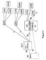
- FIG 3illustrates the configuration of the system, and by comparison with Figure 2 the modifications made according to he invention can be understood.
- the principal differenceis that the Rate Adaptive Management Box (RAMBo) 41 has been migrated from the management system 18 associated with the optical line termination 33 in the exchange to the distribution point 1. (It will be understood that each distribution point can be similarly equipped).
- RAMBoRate Adaptive Management Box
- the data collection and processing functions controlling the data rate to be used over the DSL link 30can therefore be performed at one end of that link.
- the RAMBo 41 located in the DP 1determines the data rate for itself, and only needs to communicate the required data rate to the BRAS 42 and the individual customer terminals 2, as shown by the dotted lines in Figure 3 .
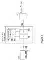
- FIG. 4depicts a node 1 (distribution point) having a wired connection 30 to customer premises equipment 2 and an optical connection 32 to a Digital subscriber line access multiplexer (DSLAM) 31.
- DSLAMDigital subscriber line access multiplexer
- Each wired customer connectionis connected to an xDSL Transmission Unit (Optical) (XTU-O) 16, and the optical connection 32 is connected through an optical network unit (ONU) 15.
- XTU-OxDSL Transmission Unit
- ONUoptical network unit
- This functionincludes the multiplexing/demultiplexing of the various customer lines over the optical connection 32.
- the dynamic line management systemis operated under the control of a Multilayer Perceptron 19.
- Figure 5shows the basic components of the Multi-layer perceptron block 19. They comprise a data collector 50 and a neural net subsystem 51, and operate in conjunction with the dynamic line management system 18 itself.
- the data collector 50gathers line data from each local modem 16.
- a pre-processing unit 52prepares the data for input to the neural network 51, by changing the format of the data into a form that can be 'read' by the MLP. Such pre-processing may take say a running average of several measurements in order to prevent too sudden a change in input parameters into the MLP which could result in wildly fluctuation DLM profile choice.
- the neural network 51assesses the data and identifies the prevailing DSL performance data, to generate an output which is then passed to a post-processor 53 for presenting the data in a form suitable for use by the DLM processor 18, which generates a profile for use by the DSL modem 16.
- the profile selected by the DLM processor 18impacts the rate at which the DSL system 16 can transmit/receive, so the profile information is also transmitted to the Broadband Remote Access Server (BRAS) 42 in the DSLAM 31.
- BRASBroadband Remote Access Server
- the DLM 18, and neural net that informs ithandles data relating to several lines 30 serving different customer premises equipment 2, so that at times of high contention (the total capacity required by he users exceeding the capabilities of the network equipment), the available capacity can be distributed fairly, for example to ensure that the level of quality of service to each user meets a respective agreed level. These capacity constraints are unlikely to be on the optical connection 32 itself, but in the DSLAM 31 and ONU 15 between which it is connected.
- the inputs to the dynamic line management system 18may include data on the RF environment, to allow frequencies subject to local interference to be excluded from the transmissions over the wired local connection 30.
- Such a systemis described in the applicant's co-pending International patent application claiming priority from European application 09250100.6 , entitled Telecommunications Connections Management, and subsequently published as WO2010/082014 .
Landscapes
- Engineering & Computer Science (AREA)
- Computer Networks & Wireless Communication (AREA)
- Signal Processing (AREA)
- Artificial Intelligence (AREA)
- Computer Vision & Pattern Recognition (AREA)
- Databases & Information Systems (AREA)
- Evolutionary Computation (AREA)
- Medical Informatics (AREA)
- Software Systems (AREA)
- Data Exchanges In Wide-Area Networks (AREA)
- Telephonic Communication Services (AREA)
Description
- This invention relates to telecommunications systems and in particular to the management of network equipment interfacing between a network and individual customer premises systems. Such equipment is widely dispersed geographically, and has to operate without direct human supervision and in a wide variety of environments and circumstances.
- As shown in
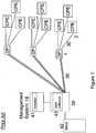
Figure 1 , in conventional Digital Subscriber Loop (DSL) services, provided from the exchange 39 (or cabinet), eachcustomer premises 2 has a dedicatedphysical connection 30 to the DSL access multiplexer (DSLAM) 31 in theexchange 39. The connections from theexchange 39 to severaldifferent customer premises 2 may pass through asingle distribution point 1, but each connection is a complete end-to-end connection. - A
management system 18 can be provided to optimise the service for each customer by maximising the data rate over the physical layer 30 (subject to a predetermined maximum) whilst maintaining the stability of the line. This is achieved for each line using a Dynamic Line Management (DLM) system and a Rate Adaptive Management Box (RAMBo) 41 which automatically selects the optimum rate profile for each line. The chosen profile rate (upstream and downstream) supported by the line is also applied to the BRAS (Broadband Remote Access Server) 42 serving theuser connection 32 so that the services provided over theDSL line 30 match the physical capabilities of the line. The BRAS is not located at the exchange but is located deeper in the network. It can handle many thousands of lines and would provide the broadband services for many exchanges). - The physical layer connectivity is provided by a Digital subscriber line access multiplexer (DSLAM) capped at a predetermined rate limit, e.g. 5Mbit/s, and the BRAS provides the services to the DSLAM so that the services are capped to the same rate limit so that there is rate matching between the physical line and the services that are applied over that line. In order to perform this function it is necessary to gather a wide selection of performance statistics from each line at regular intervals (e.g. every fifteen minutes), store these in a data-warehouse and perform subsequent post-processing of this data in order to choose the correct rate profile for each line. Also, the previous history of the line has to be accounted for in order to provide some hysteresis i.e. to prevent the line profile (rates) being changed by too much, or too frequently, both of which can result in difficulties in maintaining services such as streaming. Typical statistics gathered may include bit-rates, margins, errored seconds, severely errored seconds, and mean time between errors. These statistics are stored by a data collector and fed into the Digital
line management system 18, which is responsible for selecting an appropriate DSL profile for each line. - However, as shown in
Figure 2 , this can become difficult to achieve when fibre-to-the-distribution-point (FttDP) nodes are considered. In such systems theconnections 32 between the optical line terminal (OLT) 33 in the exchange and theindividual distribution points 1 are provided by optical fibre, each carrying the traffic for all thefinal drop connections 30 served by that distribution point. This allows the distribution point to serve a large number of customer premises. Instead of asingle DSLAM 31 providing the line statistics for thousands of lines at one convenient location, there could be a large number of remote nodes located at thedistribution points 1, each provisioning between 8 and 24 lines. - Because of the transition between optical fibre and electrical "copper" connections at the distribution points, they have more capabilities than a typical copper-to-copper distribution point. Essentially the modem conventionally located in the
DSLAM 31 at theexchange 39 is instead located in a mini-DSLAM 34 at the DP 1 (only shown for one DP inFigure 2 ). Thus the DSLAM 31 and BRAS 42 functions are no longer co-located. - As well as having some active electronics at the DP, some intelligence can be added. This allows the line characteristics to be measured at the
distribution point 1, and such an arrangement is described in International Patent Specification2007/012867 . TheDSL modem 34 located at the distribution point has the ability to draw statistics both from itself and theequivalent modem 2 on the other end of the local loop located at the customer premises (i.e. it gathers both upstream and downstream line performance statistics). - However, in this arrangement each distribution point has to transmit the periodically-gathered statistics back to the
remote data collector 43 associated with thecentral management function 18, so that its associated RAMBo (41) can set the rate for each line. This rate then needs to be communicated to both ends of theconnection 30 between thedistribution point 1 andcustomer terminal 30. The dotted lines inFigure 2 illustrate these information flows. This central data collection system adds to the operations, administration, and maintenance overhead that the network has to carry and requires a data warehouse and large central processing capabilities. Moreover all of this statistical data has to be transmitted in-band with user data, thus adding considerably to the overhead burden of the transmission system. Such a system would require a very complex line management system, and such an arrangement would be very inefficient. An additional consideration is that theoptical fibre connection 32 is unsuitable for delivering an electrical power supply from theexchange side 31, so power to operate the distribution point, including the optical/electrical transducers, has to be sourced from elsewhere. Related systems are described in published United States Patent applicationUS2004/0120390 (Brown ), and byKee Bong Song et al, ("Dynamic Spectrum Management for Next-Generation DSL Systems": IEEE Magazine October 2002). - According to the present invention, there is provided a dynamic line management system for processing data relating to the capabilities of each of a plurality of digital subscriber loops each serving a respective termination point of a telecommunications system, the dynamic line management system comprising means for generating a profile of each digital subscriber loop and setting a rate profile to allow control of the transmission of data to the individual termination points, characterised in that the dynamic line management system is associated with a network distribution point operating as a node intermediate between a remote access server and the respective digital subscriber loops, and the network distribution point is arranged to transmit data to the individual termination points under the control of the associated dynamic line management system.
- The present invention takes advantage of the data processing power available at the mini-DSLAM in each distribution point, and the availability at the DP of the data to perform dynamic line management (DLM), to make the DP autonomous in setting its own maximum stable DSL rate, by processing the data relating to line capabilities locally at the distribution points, and implementing any subsequent change of DLM profile locally. This approach still allows decisions on DLM profile choice to be made taking into account demands on neighbouring customer terminals sharing the
same DP 1. This configuration allows some of the DSLAM functions to be performed by the individual remote nodes, allowing each remote node to implement a local autonomous system using the physical layer statistics it collects, and to process them locally to provide an optimum DSL profile for each line whilst retaining system stability. In particular, theRAMBo functions 41 are migrated to thedistribution points 1. - The operational environment of each line served by the
Distribution Point 1 will be very similar, so there are advantages in implementing an autonomous DLM system at the DP. This would allow each DSL line operating from a remote node located at the DP to be optimised, based upon the local operational environment as seen at that DP. - In a fibre-to-the-distribution-point system it is impractical to power the distribution points from the exchange side because of the absence of a wired connection. The remote nodes therefore take power from the customer end of the connection. It is therefore important that power consumption is minimised.
- In one embodiment of the invention, the local processing of physical layer DSL line data is achieved using an Artificial Neural Network (ANN). The Multilayer Perceptron (MLP) is the most frequently used Artificial Neural Network, due to its ability to model non-linear systems and establish non-linear decision boundaries in classification or prediction problems. Furthermore, the MLP is a universal function approximator, which makes it a powerful tool in several signal processing fields: pattern recognition, system modelling, control, etc.
- The MLP is suitable for the field of digital line management as this application can be considered as a combination of pattern recognition (recognising specific patterns of input line statistics) and control system (changing the DLM profile accordingly). Initially it is necessary to 'train' the MLP in order to optimise the physical layer performance of the line from the gathered statistics. The computational burden of implementing an MLP lies in this initial training of the system, that is in calculating the 'weights' of the nodes and links. However, once trained, the MLP requires very little computational power in order to identify the target profile for a loop, given a set of physical layer statistics. This therefore results in low processing and power overheads, which is particularly desirable if power is to be taken from the customer side.
- Existing DLM systems using a Rate Adaptive Management Box (RAMBO) treat all lines individually, without considering local similarities between lines that share the same cable bundle etc. However, at the Distribution Point the operational environment of each line will be very similar, so there are advantages in implementing an autonomous DLM system at the DP. This would allow each DSL line operating from a remote node located at the DP to be optimised, based upon the local operational environment as seen at that DP.
- One advantage of using neural nets for such a system is that all of the processor intensive work can be performed during the training of the neural net. Once trained, the neural net is instantiated in the remote node and each analysis of the input data is a simple single iteration through the neural net, which will be just a few multiplications and additions. Therefore the computational load on the remote node processor resources will be minimal. More processing power would be required if a training algorithm is implemented to allow local adaptation at the remote node, but this training could be performed when there was plenty of spare computational resource available. As these remote nodes are powered from the CPE and that computational power (and electrical power in general) is therefore not a resource to be squandered.
- It would be possible to train a single MLP and then provide an instance of this MLP in all the remote nodes located at the Distribution Points. This would form the basis of the local DLM system in each remote node. As time progresses each MLP can be allowed to slowly mutate into a neural network optimised for the particular statistics generated by the local loops attached to that particular node.
- An embodiment will now be described with reference to
Figures 3 and4 of the drawings. Figure 1 depicts a conventional digital subscriber loop system, already discussed.Figure 2 depicts a fibre-to-the-data-point system, , already discussed.Figure 3 depicts a fibre-to-the-data-point system modified according to the invention,Figure 4 shows how the neural net digital line management system of the invention is incorporated into the network node functions.Figure 5 shows the neural net digital line management system in more detail.- It should be understood that
Figures 3 to 5 illustrate the functional elements of the system, which may in practice be embodied in one or more electronic components or in software. Figure 3 illustrates the configuration of the system, and by comparison withFigure 2 the modifications made according to he invention can be understood. The principal difference is that the Rate Adaptive Management Box (RAMBo) 41 has been migrated from themanagement system 18 associated with the optical line termination 33 in the exchange to thedistribution point 1. (It will be understood that each distribution point can be similarly equipped). The data collection and processing functions controlling the data rate to be used over theDSL link 30 can therefore be performed at one end of that link. Thus instead of measurement data sent from theDP 1 to theRAMBo 41 in an exchange-basedmanagement system 18, and the resulting data rate required returned to theDP 1, theRAMBo 41 located in theDP 1 determines the data rate for itself, and only needs to communicate the required data rate to theBRAS 42 and theindividual customer terminals 2, as shown by the dotted lines inFigure 3 .Figure 4 depicts a node 1 (distribution point) having awired connection 30 tocustomer premises equipment 2 and anoptical connection 32 to a Digital subscriber line access multiplexer (DSLAM) 31. Each wired customer connection is connected to an xDSL Transmission Unit (Optical) (XTU-O) 16, and theoptical connection 32 is connected through an optical network unit (ONU) 15. These are interlinked by ainterface unit 17 for handling functionality atlevels 2 and 3 of the standard OSI seven-level model, under the control of a dynamicline management system 18. This function includes the multiplexing/demultiplexing of the various customer lines over theoptical connection 32.- Having a local Dynamic
line management system 18 in each node reduces the requirement for processing power, memory storage requirements, and communications back to a central DLM controller. - In the present invention the dynamic line management system is operated under the control of a
Multilayer Perceptron 19. Figure 5 shows the basic components of theMulti-layer perceptron block 19. They comprise adata collector 50 and a neuralnet subsystem 51, and operate in conjunction with the dynamicline management system 18 itself.- The
data collector 50 gathers line data from eachlocal modem 16. Apre-processing unit 52 prepares the data for input to theneural network 51, by changing the format of the data into a form that can be 'read' by the MLP. Such pre-processing may take say a running average of several measurements in order to prevent too sudden a change in input parameters into the MLP which could result in wildly fluctuation DLM profile choice. Theneural network 51 assesses the data and identifies the prevailing DSL performance data, to generate an output which is then passed to a post-processor 53 for presenting the data in a form suitable for use by theDLM processor 18, which generates a profile for use by theDSL modem 16. - The profile selected by the
DLM processor 18 impacts the rate at which theDSL system 16 can transmit/receive, so the profile information is also transmitted to the Broadband Remote Access Server (BRAS) 42 in theDSLAM 31. This allows the BRAS to moderate the rate at which it transmits data, to avoid data being provided from the core IP network faster than it can be transmitted over theDSL link 30, and therefore having to be discarded. - The
DLM 18, and neural net that informs it, handles data relating toseveral lines 30 serving differentcustomer premises equipment 2, so that at times of high contention (the total capacity required by he users exceeding the capabilities of the network equipment), the available capacity can be distributed fairly, for example to ensure that the level of quality of service to each user meets a respective agreed level. These capacity constraints are unlikely to be on theoptical connection 32 itself, but in theDSLAM 31 andONU 15 between which it is connected. - The inputs to the dynamic
line management system 18 may include data on the RF environment, to allow frequencies subject to local interference to be excluded from the transmissions over the wiredlocal connection 30. Such a system is described in the applicant's co-pending International patent application claiming priority from European application09250100.6 WO2010/082014 .
Claims (12)
- A dynamic line management system (19) for processing data relating to the capabilities of each of a plurality of digital subscriber loops (30) each serving a respective termination point (2) of a telecommunications system, the dynamic line management system comprising means for generating a profile of each digital subscriber loop and setting a rate profile to allow control of the transmission of data to the individual termination points,
characterised in that the dynamic line management system is associated with a network distribution point (1) operating as a node intermediate between a remote access server (42) and the respective digital subscriber loops (30), and the network distribution point is arranged to transmit data to the individual termination points (2) under the control of the associated dynamic line management system. - A dynamic line management system according to claim 1, arranged to transmit the rate profile to the remote access server (42).
- A dynamic line management system according to claim 1 or claim 2, comprising an Artificial Neural Network for processing of data relating to the physical layer of each digital subscriber loop (30).
- A dynamic line management system according to claim 3, wherein the artificial neural network is a Multilayer Perceptron.
- A dynamic line management system according to any preceding claim wherein the network distribution point (1) is connected to the remote access server (42) is by means of an optical fibre system (32) and the connections (30) to the individual termination points (2) are made by electrical means.
- A method of controlling the transmission of data to individual network terminations (2) served from a remote access server (42) by respective digital subscriber loops (30) through one or more distribution points (1), wherein data relating to the capabilities of each of the digital subscriber loops is processed by a dynamic line management system (19) to generate a profile of each digital subscriber loop and to set a rate profile,
characterised in that the profiles of the digital subscriber loops (30) associated with the or each distribution point (2) are generated by a dynamic line management system (19) associated with the respective distribution point, and each network distribution point (2) transmits data to the individual termination points under the control of its associated dynamic line management system (19). - A method according to claim 6, wherein a rate profile is transmitted from the dynamic line management system (19) associated with the, or each, distribution point (2) to the remote access server (42).
- A method according to claim 6 or 7, wherein the dynamic line management system (19) comprises an Artificial Neural Network for processing of data relating to the physical layer of a digital subscriber loop.
- A method according to claim 8, wherein the artificial neural network is a Multilayer Perceptron.
- A method according to claim 8 or claim 9, wherein the neural net is trained prior to installation and then instantiated in the distribution point (2), and wherein each analysis of the input data is a simple single iteration through the neural net.
- A method according to claim 10, wherein after installation each neural network is allowed to mutate to allow optimisation for statistics generated by the individual subscriber connections (2) attached to the respective distribution point.
- A method according to any of claims 7, 8, 9, 10 or 11 in which the connection (32) to the remote access server (42) is an optical fibre connection and the connections (30) to the individual termination points (2) are made by electrical means.
Priority Applications (1)
| Application Number | Priority Date | Filing Date | Title |
|---|---|---|---|
| EP10700446.7AEP2377328B1 (en) | 2009-01-15 | 2010-01-07 | Management of telecommunications connections |
Applications Claiming Priority (3)
| Application Number | Priority Date | Filing Date | Title |
|---|---|---|---|
| EP09250095AEP2209324A1 (en) | 2009-01-15 | 2009-01-15 | Management of telecommunications connections |
| PCT/GB2010/000016WO2010082016A1 (en) | 2009-01-15 | 2010-01-07 | Management of telecommunications connections |
| EP10700446.7AEP2377328B1 (en) | 2009-01-15 | 2010-01-07 | Management of telecommunications connections |
Publications (2)
| Publication Number | Publication Date |
|---|---|
| EP2377328A1 EP2377328A1 (en) | 2011-10-19 |
| EP2377328B1true EP2377328B1 (en) | 2018-05-02 |
Family
ID=40721779
Family Applications (2)
| Application Number | Title | Priority Date | Filing Date |
|---|---|---|---|
| EP09250095ACeasedEP2209324A1 (en) | 2009-01-15 | 2009-01-15 | Management of telecommunications connections |
| EP10700446.7AActiveEP2377328B1 (en) | 2009-01-15 | 2010-01-07 | Management of telecommunications connections |
Family Applications Before (1)
| Application Number | Title | Priority Date | Filing Date |
|---|---|---|---|
| EP09250095ACeasedEP2209324A1 (en) | 2009-01-15 | 2009-01-15 | Management of telecommunications connections |
Country Status (3)
| Country | Link |
|---|---|
| US (1) | US10834486B2 (en) |
| EP (2) | EP2209324A1 (en) |
| WO (1) | WO2010082016A1 (en) |
Families Citing this family (21)
| Publication number | Priority date | Publication date | Assignee | Title |
|---|---|---|---|---|
| CN101233780B (en)* | 2005-07-29 | 2012-08-22 | 英国电讯有限公司 | Method and apparatus for communicating data over a data network |
| EP2169980A1 (en) | 2008-09-30 | 2010-03-31 | BRITISH TELECOMMUNICATIONS public limited company | Dynamic line management |
| EP2209324A1 (en) | 2009-01-15 | 2010-07-21 | BRITISH TELECOMMUNICATIONS public limited company | Management of telecommunications connections |
| EP2209325A1 (en) | 2009-01-15 | 2010-07-21 | BRITISH TELECOMMUNICATIONS public limited company | Management of telecommunications connections |
| EP2237478A1 (en) | 2009-03-31 | 2010-10-06 | BRITISH TELECOMMUNICATIONS public limited company | Dynamic line management |
| EP2437434A1 (en)* | 2010-09-30 | 2012-04-04 | British Telecommunications Public Limited Company | Monitoring of data traffic based on user profiles |
| CN103686466B (en) | 2012-09-12 | 2016-12-21 | 华为技术有限公司 | The method and apparatus generating forwarding-table item for the equipment in optical-fiber network |
| EP2830302A1 (en) | 2013-07-23 | 2015-01-28 | British Telecommunications public limited company | Reverse powering system for telecommunications node |
| WO2015101764A1 (en) | 2013-12-31 | 2015-07-09 | British Telecommunications Public Limited Company | Method and apparatus for use in supplying power over a telephone line |
| CN106464766B (en) | 2014-05-30 | 2019-12-24 | 英国电讯有限公司 | Method for controlling access network, access network node |
| WO2016026688A1 (en) | 2014-08-20 | 2016-02-25 | British Telecommunications Public Limited Company | Reverse power feed system |
| WO2016026656A1 (en) | 2014-08-22 | 2016-02-25 | British Telecommunications Public Limited Company | Small cell resource allocation |
| CN107889116B (en) | 2016-09-30 | 2022-05-10 | 英国电讯有限公司 | Configuration method and device of multi-level cell or cell cluster and communication system |
| CN107889117B (en) | 2016-09-30 | 2022-05-10 | 英国电讯有限公司 | Resource allocation device, resource allocation method and communication system for small cell cluster |
| CN107889127B (en) | 2016-09-30 | 2022-08-16 | 英国电讯有限公司 | Resource management method, device and communication system for cell cluster |
| WO2018087106A1 (en) | 2016-11-08 | 2018-05-17 | British Telecommunications Public Limited Company | Method and apparatus for operating a digital subscriber line arrangement |
| EP3539282B1 (en) | 2016-11-08 | 2021-05-26 | British Telecommunications Public Limited Company | Method and apparatus for operating a digital subscriber line arrangement |
| CN110089052B (en) | 2016-12-21 | 2022-02-08 | 英国电讯有限公司 | Network node and communication network |
| GB2578269A (en)* | 2018-03-28 | 2020-05-06 | British Telecomm | Network |
| CN112243166B (en)* | 2019-07-19 | 2023-04-07 | 上海诺基亚贝尔股份有限公司 | Method, apparatus, device and computer readable medium for optical communication |
| EP3879802B1 (en)* | 2020-03-11 | 2023-12-27 | Deutsche Telekom AG | Method and device for selecting a dsl connection profile for a dsl connection |
Family Cites Families (61)
| Publication number | Priority date | Publication date | Assignee | Title |
|---|---|---|---|---|
| US5134685A (en)* | 1990-02-06 | 1992-07-28 | Westinghouse Electric Corp. | Neural node, a netowrk and a chaotic annealing optimization method for the network |
| US5889470A (en) | 1996-12-24 | 1999-03-30 | Paradyne Corporation | Digital subscriber line access device management information base |
| US20030026282A1 (en)* | 1998-01-16 | 2003-02-06 | Aware, Inc. | Splitterless multicarrier modem |
| CA2240596A1 (en) | 1997-11-28 | 1999-05-28 | Newbridge Networks Corporation | Controlling atm layer transfer characteristics based on physical layer dynamic rate adaptation |
| US6588016B1 (en) | 1998-06-30 | 2003-07-01 | Cisco Technology, Inc. | Method and apparatus for locating a faulty component in a cable television system having cable modems |
| US6374288B1 (en) | 1999-01-19 | 2002-04-16 | At&T Corp | Digital subscriber line server system and method for dynamically changing bit rates in response to user requests and to message types |
| US6473851B1 (en)* | 1999-03-11 | 2002-10-29 | Mark E Plutowski | System for combining plurality of input control policies to provide a compositional output control policy |
| US7006530B2 (en) | 2000-12-22 | 2006-02-28 | Wi-Lan, Inc. | Method and system for adaptively obtaining bandwidth allocation requests |
| US6580727B1 (en) | 1999-08-20 | 2003-06-17 | Texas Instruments Incorporated | Element management system for a digital subscriber line access multiplexer |
| US6879639B1 (en) | 1999-12-30 | 2005-04-12 | Tioga Technologies Inc. | Data transceiver with filtering and precoding |
| US6975597B1 (en)* | 2000-02-11 | 2005-12-13 | Avaya Technology Corp. | Automated link variant determination and protocol configuration for customer premises equipment and other network devices |
| US7149223B2 (en) | 2000-03-06 | 2006-12-12 | Juniper Networks, Inc. | Enhanced fiber nodes with CMTS capability |
| US6546089B1 (en) | 2000-05-12 | 2003-04-08 | Turnstone Systems, Inc. | Method and system for supporting a lifeline associated with voice over DSL |
| US7280529B1 (en) | 2000-05-20 | 2007-10-09 | Ciena Corporation | Providing network management access through user profiles |
| US7076556B1 (en) | 2000-07-31 | 2006-07-11 | Cisco Technology, Inc. | Method and apparatus for storage and retrieval of connection data in a communications system |
| WO2002012497A2 (en) | 2000-08-03 | 2002-02-14 | Genaissance Pharmaceuticals, Inc. | Haplotypes of the nfkbib gene |
| US20020065902A1 (en) | 2000-09-05 | 2002-05-30 | Janik Craig M. | Webpad and method for using the same |
| WO2002035793A1 (en) | 2000-10-26 | 2002-05-02 | British Telecommunications Public Limited Company | Telecommunications routing |
| US6470059B2 (en) | 2000-12-28 | 2002-10-22 | Sbc Technology Resources, Inc. | Automatic filter for asymmetric digital subscriber line system |
| US7035249B2 (en) | 2001-03-28 | 2006-04-25 | Intel Corporation | Optimizing bandwidth of DSL connections |
| WO2003009541A1 (en) | 2001-07-20 | 2003-01-30 | Thomson Licensing S.A. | Dynamic traffic bandwidth management system and method for a communication network |
| US7047304B2 (en)* | 2001-08-14 | 2006-05-16 | The Directv Group, Inc. | System and method for provisioning broadband service in a PPPoE network using a configuration domain name |
| US6798769B1 (en) | 2001-09-13 | 2004-09-28 | Pedestal Networks, Inc. | System for enhancing data transfer |
| US20030236760A1 (en)* | 2002-06-05 | 2003-12-25 | Alex Nugent | Multi-layer training in a physical neural network formed utilizing nanotechnology |
| KR100487121B1 (en) | 2002-03-19 | 2005-05-03 | 삼성전자주식회사 | System for Service Quality Administration of Asymmetric Digital Subscriber Line |
| US7752151B2 (en)* | 2002-06-05 | 2010-07-06 | Knowmtech, Llc | Multilayer training in a physical neural network formed utilizing nanotechnology |
| US7489693B2 (en)* | 2002-09-18 | 2009-02-10 | Conexant Systems, Inc. | Method and apparatus for automatically detecting virtual circuit settings and encapsulation types in a DSL network |
| US7058122B2 (en)* | 2002-12-23 | 2006-06-06 | Sbc Properties, L.P. | Remote customer profile adaptive operating system |
| US7013244B2 (en)* | 2003-02-10 | 2006-03-14 | Dmitry Cherkassky | Method and system for estimation of quantities corrupted by noise and use of estimates in decision making |
| BRPI0409415A (en) | 2003-04-14 | 2006-04-25 | Huawei Tech Co Ltd | subscriber digital circuit terminal equipment management system |
| US20050021739A1 (en) | 2003-05-15 | 2005-01-27 | Carter Sharon E. | Methods, systems and computer program products for communicating the expected efficacy of invoking a network turbo boost service |
| US20050021716A1 (en) | 2003-05-15 | 2005-01-27 | Maria Adamczyk | Methods, systems and computer program products for authentication of session requests from service providers in communication networks |
| US7684432B2 (en) | 2003-05-15 | 2010-03-23 | At&T Intellectual Property I, L.P. | Methods of providing data services over data networks and related data networks, data service providers, routing gateways and computer program products |
| US7277513B2 (en) | 2003-08-28 | 2007-10-02 | Texas Instruments Incorporated | Frequency domain notching with dummy subchannels |
| US7706295B2 (en) | 2003-09-09 | 2010-04-27 | Marvell Semiconductor, Inc. | Methods and apparatus for breaking and resynchronizing a data link |
| EP3264683A1 (en) | 2003-12-07 | 2018-01-03 | Adaptive Spectrum and Signal Alignment, Inc. | Adaptive margin and band control |
| US7302379B2 (en) | 2003-12-07 | 2007-11-27 | Adaptive Spectrum And Signal Alignment, Inc. | DSL system estimation and parameter recommendation |
| US7317754B1 (en) | 2004-01-12 | 2008-01-08 | Verizon Services Corp. | Rate agile rate-adaptive digital subscriber line |
| JP4320603B2 (en)* | 2004-02-26 | 2009-08-26 | 日本電気株式会社 | Subscriber line accommodation apparatus and packet filtering method |
| CN1926805B (en)* | 2004-03-23 | 2011-05-18 | 意大利电信股份公司 | System and method for analyzing quality status of access network supporting broadband telecommunication services |
| US7570599B2 (en) | 2004-04-21 | 2009-08-04 | At&T Intellectual Property I, Llp. | Adaptively applying a target noise margin to a digital subscriber line (DSL) loop for DSL data rate establishment |
| US7400720B2 (en) | 2004-10-05 | 2008-07-15 | Sbc Knowledge Ventures, L.P. | System and method for optimizing digital subscriber line based services |
| EP1662717A1 (en) | 2004-11-26 | 2006-05-31 | Alcatel | Improved restoration in a telecommunication network |
| US7440728B2 (en) | 2004-12-03 | 2008-10-21 | Microsoft Corporation | Use of separate control channel to mitigate interference problems in wireless networking |
| US7460588B2 (en)* | 2005-03-03 | 2008-12-02 | Adaptive Spectrum And Signal Alignment, Inc. | Digital subscriber line (DSL) state and line profile control |
| US20060224532A1 (en)* | 2005-03-09 | 2006-10-05 | Case Western Reserve University | Iterative feature weighting with neural networks |
| EP1748671A1 (en) | 2005-07-29 | 2007-01-31 | BRITISH TELECOMMUNICATIONS public limited company | Method and apparatus for communicating data over a data network |
| CN101233780B (en)* | 2005-07-29 | 2012-08-22 | 英国电讯有限公司 | Method and apparatus for communicating data over a data network |
| DE602005000993T2 (en) | 2005-09-16 | 2007-09-06 | Alcatel Lucent | Method and module for network analysis |
| US7496548B1 (en)* | 2005-09-26 | 2009-02-24 | Quintura, Inc. | Neural network for electronic search applications |
| US7986686B2 (en)* | 2005-11-25 | 2011-07-26 | Cisco Technology, Inc. | Techniques for distributing network provider digital content to customer premises nodes |
| US8068584B2 (en) | 2006-10-26 | 2011-11-29 | At&T Intellectual Property I, Lp | System and method for selecting a profile for a digital subscriber line |
| EP1953959A1 (en) | 2007-02-01 | 2008-08-06 | British Telecommunications Public Limited Company | Data communication |
| CN101312361B (en) | 2007-05-23 | 2013-08-07 | 华为技术有限公司 | Digital subscriber line parameter collecting method, module and circuit management system |
| WO2009010726A1 (en) | 2007-07-13 | 2009-01-22 | British Telecommunications Public Limited Company | Method and apparatus for communicating data over a data network |
| EP2073439A1 (en)* | 2007-12-21 | 2009-06-24 | British Telecmmunications public limited campany | Data communication |
| EP2073446A1 (en) | 2007-12-21 | 2009-06-24 | British Telecmmunications public limited campany | Monitoring of network connections |
| EP2169980A1 (en)* | 2008-09-30 | 2010-03-31 | BRITISH TELECOMMUNICATIONS public limited company | Dynamic line management |
| EP2209324A1 (en) | 2009-01-15 | 2010-07-21 | BRITISH TELECOMMUNICATIONS public limited company | Management of telecommunications connections |
| EP2209325A1 (en) | 2009-01-15 | 2010-07-21 | BRITISH TELECOMMUNICATIONS public limited company | Management of telecommunications connections |
| EP2237478A1 (en)* | 2009-03-31 | 2010-10-06 | BRITISH TELECOMMUNICATIONS public limited company | Dynamic line management |
- 2009
- 2009-01-15EPEP09250095Apatent/EP2209324A1/ennot_activeCeased
- 2010
- 2010-01-07USUS13/144,904patent/US10834486B2/enactiveActive
- 2010-01-07WOPCT/GB2010/000016patent/WO2010082016A1/enactiveApplication Filing
- 2010-01-07EPEP10700446.7Apatent/EP2377328B1/enactiveActive
Non-Patent Citations (1)
| Title |
|---|
| None* |
Also Published As
| Publication number | Publication date |
|---|---|
| EP2377328A1 (en) | 2011-10-19 |
| US20110274009A1 (en) | 2011-11-10 |
| US10834486B2 (en) | 2020-11-10 |
| WO2010082016A1 (en) | 2010-07-22 |
| EP2209324A1 (en) | 2010-07-21 |
Similar Documents
| Publication | Publication Date | Title |
|---|---|---|
| EP2377328B1 (en) | Management of telecommunications connections | |
| EP2377327B1 (en) | Dynamic line management | |
| US6069894A (en) | Enhancement of network operation and performance | |
| CN104509031B (en) | Selection is to the system and method for the parameter being compressed for the coefficient of node scale vector quantization | |
| US6388990B1 (en) | Method and system for reducing congestion in connection-oriented packet networks having digital subscriber line access | |
| EP3829080A1 (en) | Pon fault location method and device | |
| EP1911256B1 (en) | User-preference-based dsl system | |
| US20010040899A1 (en) | Method and apparatus for bandwidth management in a digital loop carrier system | |
| US20090262647A1 (en) | Method and Apparatus for Communication Data Over a Data Network | |
| WO1995034981A2 (en) | Enhancement of network operation and performance | |
| US11444834B2 (en) | Methods, systems, and apparatuses for implementing upstream power control for DSL | |
| CN104335495A (en) | Apparatus, systems and methods for DSM energy management | |
| CN120321136B (en) | Intelligent optimization and resource dynamic reallocation method and system based on graph neural network | |
| KR101591211B1 (en) | Access node for a communication network | |
| CN119893537A (en) | Wireless network optimization system based on artificial intelligence | |
| US8649484B2 (en) | Apparatus, methods, and articles of manufacture to predict vectored digital subscriber line (DSL) performance gains | |
| CN105874729A (en) | Apparatus and method for accessing network | |
| JP2004134968A (en) | Subscriber transmission system and dynamic band assignment method for subscriber transmission system | |
| US12199692B2 (en) | Network optimization for mitigation of crosstalk between network links | |
| CN120128837B (en) | Method and system for processing downlink bandwidth allocation information | |
| EP2770715A1 (en) | Method for migrating VHBB services from ADSL/2/2+ technique to VDSL2 technique | |
| Perez | IPTV on copper-lines converging into “all-optical” trunk transport: A next-generation local-loop solution | |
| WO2000010274A1 (en) | Method and apparatus for collect information in a digital loop carrier system | |
| MXPA06001848A (en) | System and method for auto sensing and provisioning two or four wire mode on a communications line with rate adaptation. |
Legal Events
| Date | Code | Title | Description |
|---|---|---|---|
| PUAI | Public reference made under article 153(3) epc to a published international application that has entered the european phase | Free format text:ORIGINAL CODE: 0009012 | |
| 17P | Request for examination filed | Effective date:20110616 | |
| AK | Designated contracting states | Kind code of ref document:A1 Designated state(s):AT BE BG CH CY CZ DE DK EE ES FI FR GB GR HR HU IE IS IT LI LT LU LV MC MK MT NL NO PL PT RO SE SI SK SM TR | |
| DAX | Request for extension of the european patent (deleted) | ||
| STAA | Information on the status of an ep patent application or granted ep patent | Free format text:STATUS: EXAMINATION IS IN PROGRESS | |
| 17Q | First examination report despatched | Effective date:20170307 | |
| RAP1 | Party data changed (applicant data changed or rights of an application transferred) | Owner name:BRITISH TELECOMMUNICATIONS PUBLIC LIMITED COMPANY | |
| GRAP | Despatch of communication of intention to grant a patent | Free format text:ORIGINAL CODE: EPIDOSNIGR1 | |
| STAA | Information on the status of an ep patent application or granted ep patent | Free format text:STATUS: GRANT OF PATENT IS INTENDED | |
| RIC1 | Information provided on ipc code assigned before grant | Ipc:H04L 12/24 20060101ALI20180130BHEP Ipc:H04Q 11/04 20060101AFI20180130BHEP Ipc:H04L 12/28 20060101ALI20180130BHEP Ipc:H04M 3/30 20060101ALI20180130BHEP | |
| INTG | Intention to grant announced | Effective date:20180215 | |
| GRAS | Grant fee paid | Free format text:ORIGINAL CODE: EPIDOSNIGR3 | |
| GRAA | (expected) grant | Free format text:ORIGINAL CODE: 0009210 | |
| STAA | Information on the status of an ep patent application or granted ep patent | Free format text:STATUS: THE PATENT HAS BEEN GRANTED | |
| AK | Designated contracting states | Kind code of ref document:B1 Designated state(s):AT BE BG CH CY CZ DE DK EE ES FI FR GB GR HR HU IE IS IT LI LT LU LV MC MK MT NL NO PL PT RO SE SI SK SM TR | |
| REG | Reference to a national code | Ref country code:GB Ref legal event code:FG4D | |
| REG | Reference to a national code | Ref country code:CH Ref legal event code:EP Ref country code:AT Ref legal event code:REF Ref document number:996482 Country of ref document:AT Kind code of ref document:T Effective date:20180515 | |
| REG | Reference to a national code | Ref country code:DE Ref legal event code:R096 Ref document number:602010050337 Country of ref document:DE Ref country code:IE Ref legal event code:FG4D | |
| REG | Reference to a national code | Ref country code:NL Ref legal event code:MP Effective date:20180502 | |
| REG | Reference to a national code | Ref country code:LT Ref legal event code:MG4D | |
| PG25 | Lapsed in a contracting state [announced via postgrant information from national office to epo] | Ref country code:ES Free format text:LAPSE BECAUSE OF FAILURE TO SUBMIT A TRANSLATION OF THE DESCRIPTION OR TO PAY THE FEE WITHIN THE PRESCRIBED TIME-LIMIT Effective date:20180502 Ref country code:NO Free format text:LAPSE BECAUSE OF FAILURE TO SUBMIT A TRANSLATION OF THE DESCRIPTION OR TO PAY THE FEE WITHIN THE PRESCRIBED TIME-LIMIT Effective date:20180802 Ref country code:BG Free format text:LAPSE BECAUSE OF FAILURE TO SUBMIT A TRANSLATION OF THE DESCRIPTION OR TO PAY THE FEE WITHIN THE PRESCRIBED TIME-LIMIT Effective date:20180802 Ref country code:LT Free format text:LAPSE BECAUSE OF FAILURE TO SUBMIT A TRANSLATION OF THE DESCRIPTION OR TO PAY THE FEE WITHIN THE PRESCRIBED TIME-LIMIT Effective date:20180502 Ref country code:FI Free format text:LAPSE BECAUSE OF FAILURE TO SUBMIT A TRANSLATION OF THE DESCRIPTION OR TO PAY THE FEE WITHIN THE PRESCRIBED TIME-LIMIT Effective date:20180502 Ref country code:SE Free format text:LAPSE BECAUSE OF FAILURE TO SUBMIT A TRANSLATION OF THE DESCRIPTION OR TO PAY THE FEE WITHIN THE PRESCRIBED TIME-LIMIT Effective date:20180502 | |
| PG25 | Lapsed in a contracting state [announced via postgrant information from national office to epo] | Ref country code:HR Free format text:LAPSE BECAUSE OF FAILURE TO SUBMIT A TRANSLATION OF THE DESCRIPTION OR TO PAY THE FEE WITHIN THE PRESCRIBED TIME-LIMIT Effective date:20180502 Ref country code:GR Free format text:LAPSE BECAUSE OF FAILURE TO SUBMIT A TRANSLATION OF THE DESCRIPTION OR TO PAY THE FEE WITHIN THE PRESCRIBED TIME-LIMIT Effective date:20180803 Ref country code:LV Free format text:LAPSE BECAUSE OF FAILURE TO SUBMIT A TRANSLATION OF THE DESCRIPTION OR TO PAY THE FEE WITHIN THE PRESCRIBED TIME-LIMIT Effective date:20180502 Ref country code:NL Free format text:LAPSE BECAUSE OF FAILURE TO SUBMIT A TRANSLATION OF THE DESCRIPTION OR TO PAY THE FEE WITHIN THE PRESCRIBED TIME-LIMIT Effective date:20180502 | |
| REG | Reference to a national code | Ref country code:AT Ref legal event code:MK05 Ref document number:996482 Country of ref document:AT Kind code of ref document:T Effective date:20180502 | |
| PG25 | Lapsed in a contracting state [announced via postgrant information from national office to epo] | Ref country code:PT Free format text:LAPSE BECAUSE OF FAILURE TO SUBMIT A TRANSLATION OF THE DESCRIPTION OR TO PAY THE FEE WITHIN THE PRESCRIBED TIME-LIMIT Effective date:20180903 | |
| PG25 | Lapsed in a contracting state [announced via postgrant information from national office to epo] | Ref country code:CZ Free format text:LAPSE BECAUSE OF FAILURE TO SUBMIT A TRANSLATION OF THE DESCRIPTION OR TO PAY THE FEE WITHIN THE PRESCRIBED TIME-LIMIT Effective date:20180502 Ref country code:RO Free format text:LAPSE BECAUSE OF FAILURE TO SUBMIT A TRANSLATION OF THE DESCRIPTION OR TO PAY THE FEE WITHIN THE PRESCRIBED TIME-LIMIT Effective date:20180502 Ref country code:SK Free format text:LAPSE BECAUSE OF FAILURE TO SUBMIT A TRANSLATION OF THE DESCRIPTION OR TO PAY THE FEE WITHIN THE PRESCRIBED TIME-LIMIT Effective date:20180502 Ref country code:EE Free format text:LAPSE BECAUSE OF FAILURE TO SUBMIT A TRANSLATION OF THE DESCRIPTION OR TO PAY THE FEE WITHIN THE PRESCRIBED TIME-LIMIT Effective date:20180502 Ref country code:PL Free format text:LAPSE BECAUSE OF FAILURE TO SUBMIT A TRANSLATION OF THE DESCRIPTION OR TO PAY THE FEE WITHIN THE PRESCRIBED TIME-LIMIT Effective date:20180502 Ref country code:AT Free format text:LAPSE BECAUSE OF FAILURE TO SUBMIT A TRANSLATION OF THE DESCRIPTION OR TO PAY THE FEE WITHIN THE PRESCRIBED TIME-LIMIT Effective date:20180502 Ref country code:DK Free format text:LAPSE BECAUSE OF FAILURE TO SUBMIT A TRANSLATION OF THE DESCRIPTION OR TO PAY THE FEE WITHIN THE PRESCRIBED TIME-LIMIT Effective date:20180502 | |
| REG | Reference to a national code | Ref country code:DE Ref legal event code:R097 Ref document number:602010050337 Country of ref document:DE | |
| PG25 | Lapsed in a contracting state [announced via postgrant information from national office to epo] | Ref country code:IT Free format text:LAPSE BECAUSE OF FAILURE TO SUBMIT A TRANSLATION OF THE DESCRIPTION OR TO PAY THE FEE WITHIN THE PRESCRIBED TIME-LIMIT Effective date:20180502 Ref country code:SM Free format text:LAPSE BECAUSE OF FAILURE TO SUBMIT A TRANSLATION OF THE DESCRIPTION OR TO PAY THE FEE WITHIN THE PRESCRIBED TIME-LIMIT Effective date:20180502 | |
| PLBE | No opposition filed within time limit | Free format text:ORIGINAL CODE: 0009261 | |
| STAA | Information on the status of an ep patent application or granted ep patent | Free format text:STATUS: NO OPPOSITION FILED WITHIN TIME LIMIT | |
| 26N | No opposition filed | Effective date:20190205 | |
| PG25 | Lapsed in a contracting state [announced via postgrant information from national office to epo] | Ref country code:SI Free format text:LAPSE BECAUSE OF FAILURE TO SUBMIT A TRANSLATION OF THE DESCRIPTION OR TO PAY THE FEE WITHIN THE PRESCRIBED TIME-LIMIT Effective date:20180502 | |
| PG25 | Lapsed in a contracting state [announced via postgrant information from national office to epo] | Ref country code:MC Free format text:LAPSE BECAUSE OF FAILURE TO SUBMIT A TRANSLATION OF THE DESCRIPTION OR TO PAY THE FEE WITHIN THE PRESCRIBED TIME-LIMIT Effective date:20180502 | |
| REG | Reference to a national code | Ref country code:CH Ref legal event code:PL | |
| PG25 | Lapsed in a contracting state [announced via postgrant information from national office to epo] | Ref country code:LU Free format text:LAPSE BECAUSE OF NON-PAYMENT OF DUE FEES Effective date:20190107 | |
| REG | Reference to a national code | Ref country code:BE Ref legal event code:MM Effective date:20190131 | |
| REG | Reference to a national code | Ref country code:IE Ref legal event code:MM4A | |
| PG25 | Lapsed in a contracting state [announced via postgrant information from national office to epo] | Ref country code:BE Free format text:LAPSE BECAUSE OF NON-PAYMENT OF DUE FEES Effective date:20190131 | |
| PG25 | Lapsed in a contracting state [announced via postgrant information from national office to epo] | Ref country code:LI Free format text:LAPSE BECAUSE OF NON-PAYMENT OF DUE FEES Effective date:20190131 Ref country code:CH Free format text:LAPSE BECAUSE OF NON-PAYMENT OF DUE FEES Effective date:20190131 | |
| PG25 | Lapsed in a contracting state [announced via postgrant information from national office to epo] | Ref country code:IE Free format text:LAPSE BECAUSE OF NON-PAYMENT OF DUE FEES Effective date:20190107 | |
| PG25 | Lapsed in a contracting state [announced via postgrant information from national office to epo] | Ref country code:TR Free format text:LAPSE BECAUSE OF FAILURE TO SUBMIT A TRANSLATION OF THE DESCRIPTION OR TO PAY THE FEE WITHIN THE PRESCRIBED TIME-LIMIT Effective date:20180502 | |
| PG25 | Lapsed in a contracting state [announced via postgrant information from national office to epo] | Ref country code:MT Free format text:LAPSE BECAUSE OF NON-PAYMENT OF DUE FEES Effective date:20190107 | |
| PG25 | Lapsed in a contracting state [announced via postgrant information from national office to epo] | Ref country code:CY Free format text:LAPSE BECAUSE OF FAILURE TO SUBMIT A TRANSLATION OF THE DESCRIPTION OR TO PAY THE FEE WITHIN THE PRESCRIBED TIME-LIMIT Effective date:20180502 | |
| PG25 | Lapsed in a contracting state [announced via postgrant information from national office to epo] | Ref country code:IS Free format text:LAPSE BECAUSE OF FAILURE TO SUBMIT A TRANSLATION OF THE DESCRIPTION OR TO PAY THE FEE WITHIN THE PRESCRIBED TIME-LIMIT Effective date:20180902 | |
| PG25 | Lapsed in a contracting state [announced via postgrant information from national office to epo] | Ref country code:HU Free format text:LAPSE BECAUSE OF FAILURE TO SUBMIT A TRANSLATION OF THE DESCRIPTION OR TO PAY THE FEE WITHIN THE PRESCRIBED TIME-LIMIT; INVALID AB INITIO Effective date:20100107 | |
| PG25 | Lapsed in a contracting state [announced via postgrant information from national office to epo] | Ref country code:MK Free format text:LAPSE BECAUSE OF FAILURE TO SUBMIT A TRANSLATION OF THE DESCRIPTION OR TO PAY THE FEE WITHIN THE PRESCRIBED TIME-LIMIT Effective date:20180502 | |
| P01 | Opt-out of the competence of the unified patent court (upc) registered | Effective date:20230623 | |
| PGFP | Annual fee paid to national office [announced via postgrant information from national office to epo] | Ref country code:GB Payment date:20241219 Year of fee payment:16 | |
| PGFP | Annual fee paid to national office [announced via postgrant information from national office to epo] | Ref country code:FR Payment date:20241220 Year of fee payment:16 | |
| PGFP | Annual fee paid to national office [announced via postgrant information from national office to epo] | Ref country code:DE Payment date:20241218 Year of fee payment:16 |