EP2374424B1 - Dynamic stabilization system using polyaxial screws - Google Patents
Dynamic stabilization system using polyaxial screwsDownload PDFInfo
- Publication number
- EP2374424B1 EP2374424B1EP11161378.2AEP11161378AEP2374424B1EP 2374424 B1EP2374424 B1EP 2374424B1EP 11161378 AEP11161378 AEP 11161378AEP 2374424 B1EP2374424 B1EP 2374424B1
- Authority
- EP
- European Patent Office
- Prior art keywords
- insert
- housing
- cord
- fastener
- stabilization system
- Prior art date
- Legal status (The legal status is an assumption and is not a legal conclusion. Google has not performed a legal analysis and makes no representation as to the accuracy of the status listed.)
- Not-in-force
Links
- 230000006641stabilisationEffects0.000titleclaimsdescription48
- 238000011105stabilizationMethods0.000titleclaimsdescription48
- 125000006850spacer groupChemical group0.000claimsdescription33
- 230000006835compressionEffects0.000claimsdescription5
- 238000007906compressionMethods0.000claimsdescription5
- 230000037361pathwayEffects0.000claimsdescription3
- 230000002093peripheral effectEffects0.000claimsdescription3
- 230000000994depressogenic effectEffects0.000claims1
- 239000000463materialSubstances0.000description8
- 238000000034methodMethods0.000description5
- 230000000694effectsEffects0.000description4
- 208000002193PainDiseases0.000description3
- 210000000988bone and boneAnatomy0.000description3
- 210000002517zygapophyseal jointAnatomy0.000description3
- 230000004927fusionEffects0.000description2
- 238000002513implantationMethods0.000description2
- 239000002184metalSubstances0.000description2
- 230000035515penetrationEffects0.000description2
- 229920001692polycarbonate urethanePolymers0.000description2
- 229920000139polyethylene terephthalatePolymers0.000description2
- 239000005020polyethylene terephthalateSubstances0.000description2
- 230000000087stabilizing effectEffects0.000description2
- 208000011580syndromic diseaseDiseases0.000description2
- UUTKICFRNVKFRG-WDSKDSINSA-N(4R)-3-[oxo-[(2S)-5-oxo-2-pyrrolidinyl]methyl]-4-thiazolidinecarboxylic acidChemical compoundOC(=O)[C@@H]1CSCN1C(=O)[C@H]1NC(=O)CC1UUTKICFRNVKFRG-WDSKDSINSA-N0.000description1
- 208000008035Back PainDiseases0.000description1
- 208000003618Intervertebral Disc DisplacementDiseases0.000description1
- 208000008930Low Back PainDiseases0.000description1
- 230000000712assemblyEffects0.000description1
- 238000000429assemblyMethods0.000description1
- 230000003412degenerative effectEffects0.000description1
- 230000001771impaired effectEffects0.000description1
- 238000009434installationMethods0.000description1
- 208000005198spinal stenosisDiseases0.000description1
- 238000001356surgical procedureMethods0.000description1
Images


Classifications
- A—HUMAN NECESSITIES
- A61—MEDICAL OR VETERINARY SCIENCE; HYGIENE
- A61B—DIAGNOSIS; SURGERY; IDENTIFICATION
- A61B17/00—Surgical instruments, devices or methods
- A61B17/56—Surgical instruments or methods for treatment of bones or joints; Devices specially adapted therefor
- A61B17/58—Surgical instruments or methods for treatment of bones or joints; Devices specially adapted therefor for osteosynthesis, e.g. bone plates, screws or setting implements
- A61B17/68—Internal fixation devices, including fasteners and spinal fixators, even if a part thereof projects from the skin
- A61B17/70—Spinal positioners or stabilisers, e.g. stabilisers comprising fluid filler in an implant
- A61B17/7001—Screws or hooks combined with longitudinal elements which do not contact vertebrae
- A61B17/7002—Longitudinal elements, e.g. rods
- A61B17/7004—Longitudinal elements, e.g. rods with a cross-section which varies along its length
- A61B17/7008—Longitudinal elements, e.g. rods with a cross-section which varies along its length with parts of, or attached to, the longitudinal elements, bearing against an outside of the screw or hook heads, e.g. nuts on threaded rods
- A—HUMAN NECESSITIES
- A61—MEDICAL OR VETERINARY SCIENCE; HYGIENE
- A61B—DIAGNOSIS; SURGERY; IDENTIFICATION
- A61B17/00—Surgical instruments, devices or methods
- A61B17/56—Surgical instruments or methods for treatment of bones or joints; Devices specially adapted therefor
- A61B17/58—Surgical instruments or methods for treatment of bones or joints; Devices specially adapted therefor for osteosynthesis, e.g. bone plates, screws or setting implements
- A61B17/68—Internal fixation devices, including fasteners and spinal fixators, even if a part thereof projects from the skin
- A61B17/70—Spinal positioners or stabilisers, e.g. stabilisers comprising fluid filler in an implant
- A61B17/7001—Screws or hooks combined with longitudinal elements which do not contact vertebrae
- A61B17/7002—Longitudinal elements, e.g. rods
- A61B17/7019—Longitudinal elements having flexible parts, or parts connected together, such that after implantation the elements can move relative to each other
- A61B17/7031—Longitudinal elements having flexible parts, or parts connected together, such that after implantation the elements can move relative to each other made wholly or partly of flexible material
- A—HUMAN NECESSITIES
- A61—MEDICAL OR VETERINARY SCIENCE; HYGIENE
- A61B—DIAGNOSIS; SURGERY; IDENTIFICATION
- A61B17/00—Surgical instruments, devices or methods
- A61B17/56—Surgical instruments or methods for treatment of bones or joints; Devices specially adapted therefor
- A61B17/58—Surgical instruments or methods for treatment of bones or joints; Devices specially adapted therefor for osteosynthesis, e.g. bone plates, screws or setting implements
- A61B17/68—Internal fixation devices, including fasteners and spinal fixators, even if a part thereof projects from the skin
- A61B17/70—Spinal positioners or stabilisers, e.g. stabilisers comprising fluid filler in an implant
- A61B17/7001—Screws or hooks combined with longitudinal elements which do not contact vertebrae
- A61B17/7035—Screws or hooks, wherein a rod-clamping part and a bone-anchoring part can pivot relative to each other
- A61B17/7037—Screws or hooks, wherein a rod-clamping part and a bone-anchoring part can pivot relative to each other wherein pivoting is blocked when the rod is clamped
Definitions
- the disclosureis directed to a vertebral stabilization system. More particularly, the disclosure is directed to a dynamic stabilization system including a support construct configured to be used with poly-axial pedicle screws.
- the spinal column of a patientincludes a plurality of vertebrae linked to one another by facet joints and an intervertebral disc located between adjacent vertebrae.
- the facet joints and intervertebral discallow one vertebra to move relative to an adjacent vertebra, providing the spinal column a range of motion.
- Diseased, degenerated, damaged, or otherwise impaired facet joints and/or intervertebral discsmay cause the patient to experience pain or discomfort and/or loss of motion, thus prompting surgery to alleviate the pain and/or restore motion of the spinal column.
- One possible method of treating these conditionsis to immobilize a portion of the spine to allow treatment.
- immobilizationhas been accomplished by rigid stabilization.
- a surgeonrestores the alignment of the spine or the disc space between vertebrae by installing a rigid fixation rod between pedicle screws secured to adjacent vertebrae. Bone graft is placed between the vertebrae, and the fixation rod cooperates with the screws to immobilize the two vertebrae relative to each other so that the bone graft may fuse with the vertebrae.
- Dynamic stabilizationhas also been used in spinal treatment procedures. Dynamic stabilization does not result in complete immobilization, but instead permits a degree of mobility of the spine while also providing sufficient support and stabilization to effect treatment.
- a dynamic stabilization systemis the Dynesys® system available from Zimmer Spine, Inc. of Minneapolis, MN. Such dynamic stabilization systems typically include a flexible member positioned between pedicle screws installed in adjacent vertebrae of the spine. A flexible cord can be threaded through the bore in the flexible member and secured to the pedicle screws while cooperating with the flexible member to permit mobility of the spine.
- the pedicle screw currently used iri the Dynesys® systemis a mono-axial pedicle screw which may present limitations during installation of the Dynesys® system in some instances.
- EP1970018A2describes a spinal stabilization system including at least two anchors having a bone attachment portion and a head portion and a flexible assembly coupled to the anchors, the flexible assembly comprising a flexible cord with connectors slideably mounted to the cord and spacers slideably mounted to the cord between the connectors, where each connector couples with a head portion of an anchor.
- a spinal stabilization systemcomprising a polyaxial pedicle screw including a housing and a threaded shaft extending from the housing, the threaded shaft pivotable relative to the housing to a plurality of angular positions, the housing including a channel extending from a first side of the housing to a second side of the housing; a support construct including a spacer and a cord extendable through a lumen of the spacer; and a fastener configured to rotatably engage the housing of the polyaxial pedicle screw, characterized by: an insert positionable in the channel of the housing, the insert including an open channel extending from a first end of the insert to a second end of the insert: wherein the cord is positionable in the open channel of the insert such that a first portion of the cord extends from the first side of the housing of the polyaxial pedicle screw and a second portion of the cord extends from the second side of the housing of the polyaxial pedicle screw; and wherein rotationable engagement of the fastener with
- the polyaxial pedicle screwincludes a housing pivotably coupled to a threaded shaft.
- the housingincludes a channel extending from a first side of the housing to a second side of the housing.
- the spoolincludes a first flange, a second flange and a medial portion extending between the first flange and the second flange.
- the spoolis configured to engage the housing of the pedicle screw such that the medial portion is positioned in the channel with the first flange positioned adjacent the first side of the housing and the second flange positioned adjacent the second side of the housing.
- the spacerhas a first end, a second end and a lumen extending through the spacer from the first end to the second end.
- the first end of the spaceris positionable in abutting contact with the first flange of the spool.
- the flexible cordis configured to extend through the lumen of the spacer and through the spool such that a first portion of the flexible cord extends from the first flange of the spool and a second portion of the flexible cord extends from the second flange of the spool.
- the fasteneris configured to rotatably engage the housing of the pedicle screw to directly contact and press against the cord such that the cord is compressed between the fastener and a surface of the spool.
- a spinal fixation system 10for stabilizing a portion of a spinal column, such as one or more spinal segments of a spinal column
- a spinal segmentis intended to refer to two or more vertebrae, the intervertebral disc(s) between the vertebrae and other anatomical elements between the vertebrae.
- a spinal segmentmay include first and second adjacent vertebrae and the intervertebral disc located between the first and second vertebrae.
- the spinal stabilization system 10may provide dynamic stabilization to a spinal segment, preserving and/or allowing for a range of motion of the spinal segment.
- the spinal stabilization system 10may be used to treat discogenic low back pain, degenerative spinal stenosis, disc herniations, facet syndrome, posterior element instability, adjacent level syndrome associated with spinal fusion, and/or other maladies associated with the spinal column.
- the spinal stabilization system 10may include one or more or a plurality of vertebral anchors, depicted as pedicle screws 12.
- the vertebral anchorsmay be vertebral hooks (e.g., laminar hooks) or other types of fastening members for attachment to a bony structure such as a vertebra of the spinal column.
- Each of the pedicle screws 12may be configured to be secured to a vertebra, of a spinal column, For instance, the first pedicle screw 12a may be secured to a first vertebra and the second pedicle screw 12b may be secured to a second vertebra. Additional pedicle screws 12 may be present in instances in which the spinal stabilization system 10 spans three or more vertebra of the spinal column.
- the pedicle screw 12may include a housing 14 and a shaft 16, which may include threads 18, extending from the housing 14.
- the housing 14may include a channel such as a U-shaped channel extending from one side of the housing 14 to an opposite second side of the housing 14.
- the channel 15may be defined between opposing legs of the housing 14.
- the shaft 16may be configured to be instated into a bony region of a vertebra of the spinal column, For example, the shaft 16 may be installed into a pedicle of a vertebra, or other region of a vertebra.
- the shaft 16may extend along a longitudinal axis.
- the pedicle screw 12 depicted in the Figuresis a poly-axial pedicle screw which allows the housing 14 to be pivotable relative to the shaft 16 to a plurality of angular positions relative to the longitudinal axis.
- the pedicle screw 12, as shown in FIG. 3may include a head portion 17 at the end of the shaft 16 which is received in the housing 14.
- the housing 14may be pivotable relative to the head portion 17 of the shaft 16.
- the pedicle screw 12may include a securing element, such as a threaded fastener 20 (e.g.. a set screw, cap) configured to rotatably engage the housing 14 to secure a portion of a support construct 22 to the pedicle screw 12.
- a threaded fastener 20e.g.. a set screw, cap
- the threaded fastener 20may include threads which mate with threads formed in the housing 14
- the fastener 20may include one or more flanges, cam surfaces, or other engagement features that engage with one or more channels grooves, surfaces, or other engagement features of the housing 14 through rotation of the fastener 20.
- the fastener 20may be rotatably engaged between spaced apart legs of the housing 14 which define the channel 15 of the housing 14 therebetween.
- the spinal stabilization system 10may also include one or more, or a plurality of support constructs 22 extending between pedicle screws 12 of the spinal stabilization system 10.
- the spinal stabilization system 10 shown in FIG. 1includes a support construct 22 extending between the first pedicle screw 12a and the second pedicle screw 12b.
- the support construct 22may be constructed of a plurality of components in some instances.
- the support construct 22may include a spacer 24, and a flexible member such as a flexible cord 30 extending through the spacer 24, as weir as other components if desired.
- the spacer 24may be an annular spacer having a lumen (not shown) extending from a end 26 to a second end 28 of the spacer 24.
- the spacer 24may be a cylindrical member having a lumen extending therethrough.
- the spacer 24may be molded, extruded, or otherwise formed over and/or around the cord 30. The spacer 24 may be positioned between the housing 14 of the first pedicle screw 12a and the housing 14 of the second pedicle screw 12b.
- the spacer 24may be formed from polycarbonate urethane (PCU), although it will be recognized that various other materials suitable for implantation within the human body and for providing stabilization of the spine white maintaining flexibility may be used.
- PCUpolycarbonate urethane
- the spacer 24can be constructed of other materials such as metal, polymeric materials, or combinations of materials.
- the cord 30may extend from the housing 14 of the first pedicle screw 12a to the housing 14 of the second pedicle screw 12b.
- the cord 30may be formed from polyethylene-terephthalate (PET), although it will be recognized that various other materials suitable for implantation within the human body and for providing stabilization of the spine while maintaining flexibility may be used.
- PETpolyethylene-terephthalate
- the cord 30can be constructed of other flexible materials such as metal, polymeric materials, or combinations of flexible materials. It is noted that during a medical procedure the portions of the cord 30 which are shown extending from the channels of the pedicle screws 12a, 12b may be trimmed as desired to reduce and/or eliminate the portion of the cord 30 extending from the pedicle screws 12a, 12b.
- the cord 30 of the spinal stabilization system 10may limit the range of flexion of the spinal segment, whereas the spacer 24 may limit the range of extension of the spinal segment.
- the cord 30may be placed in tension and the spacer 24 may be placed in compression between the pedicle screws 12a, 12b.
- the spinal stabilization system 10may also include inserts 32 configured to be inserted into the channels of the housing 14 of the pedicle screws 12.
- inserts 32may be considered spools in some instances, may include a first flange 34 proximate a first end of the insert 32, a second flange 36 proximate the second end of the insert 32, and a medial portion 38 intermediate the first flange 34 and the second flange 36 and extending therebetween.
- the insert 32may have end surfaces 48 configured to abut an end surface of the spacer 24.
- an end surface 48 of an insert 32 coupled with the first pedicle screw 12amay abut an end surface of the spacer 24 proximate the first end 26 of the spacer 24 and an end surface 48 of an insert 32 coupled with the second pedicle screw 12b may abut an end surface of the spacer 24 proximate the second end 28 of the spacer 24.
- the insert 32may be configured such that the medial portion 38 is positionable in the channel 15 (shown in FIG. 3 ) of the housing 14 of the pedicle screw 12 with the first flange 34 positioned exterior of the housing 14 and facing the first side of the housing 14 and the second flange 36 positioned exterior of the housing 14 and facing the second side of the housing 14.
- the insert 32may be positioned in the channel 15 in a top-loaded fashion in which the insert 32 is moved into the channel 15 of the housing 14 in a direction generally perpendicular to the longitudinal axis of the channel 15 of the housing 14.
- the insert 32may include an open channel 40 extending from the first end of the insert 32 to the second end of the insert 32 along a axis parallel to the longitudinal axis of the channel 15 through the housing 14.
- the term "open channel”is intended to refer to a conduit which is not enclosed by a peripheral surface extending entirely around a periphery of the conduit.
- the open channel 40may be open to the exterior of the insert 32 along at least a portion of its length in addition to being open at its ends such the open channel 40 is open laterally from the longitudinal axis of the open channel 40.
- the open channel 40may otherwise be referred to as a furrow, recess or depression extending from the first end of the insert 32 to the second end of the insert 32.
- the open channel 40may be configured to receive the cord 30 therein.
- the open channel 40allows the cord 30 to be inserted into the open channel 40 of the insert 32 in a direction generally perpendicular to the longitudinal axis of the open channel 40.
- Each of the first flange 34 and the second flange 36may include a slot 39 extending from a periphery of the flange 34, 36 to the open channel 40 to allow the cord 30 to be inserted into the open channel 40 white extending outward from the first and second flanges 34, 36.
- the open channel 40may be defined as a recessed area of the insert 32 between a first edge 42 and a second edge 44 of the insert 32.
- the first and second edges 42, 44may be upper edges or extents of the open channel 40 and/or the medial portion 38 of the insert 32. In some instances, the first and second edges 42, 44 may extend generally parallel to the longitudinal axis of the open channel 40.
- the open channel 40may include a surface 46, such as a concave surface, extending between the first and second edges 42, 44 for receipt of the cord 30 thereagainst. When implanted, the cord 30 may be compressed between the fastener 20 and the surface 46 of the insert 32.
- the surface 46may include any mechanical gripping means such as, but not limited to, one or more threads, ribs, projecting grooves, teeth, posts, spikes, and/or serrations or combination thereof.
- the mechanical gripping meansmay increase the purchase of the cord 30 between the fastener 20 and the insert 32 as will be further described herein.
- the insert 32may include a depression 54 extending into the insert 32 from the base of the concave surface 46 of the open channel 40.
- One exemplary depression 54is shown in dashed lines in FIGS. 4A and 4B as a spherically concave depression which may be axially aligned with the axis of rotation of the fastener 20 when the insert 32 is positioned in the channel 15 of the housing 14.
- the presence of the depression 54may advantageously enhance the securement of the cord 30 between the fastener 20 and the insert 32. For instance, when the cord 30 is compressed by the fastener 20, a portion of the cord 30 may be pressed into the depression 54, providing a more tortuous pathway for the cord 30 passing through the open channel 40, as shown herein at FIG. 5B .
- the depression 54is shown with regard to the configuration of FIGS. 5A and 5B , in some instances the depression 54 may not be present. Furthermore, the depression 54, while not illustrated regarding the configuration of FIGS. 6A and 6B , may be included in such a configuration, if desired.
- the presence of the insert 32 in the channel 15 of the housing 14may facilitate locking the housing 14 from poly-axial movement relative to the shaft 16 of the pedicle screw 12 when the spinal stabilization system 10 is installed, For instance a locking force exerted by the fastener 20 may be transmitted through the insert 32 to the head portion 17 of the shaft 16 to lock the housing 14 from pivotable movement relative to the head portion 17 of the shaft 16.
- the insert 32which is more rigid than the cord 30, is in direct contact with the head portion 17 of the shaft 16 to transfer the locking force exerted by the fastener 20 to the head portion 17.
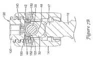
- FIGS. 5A and 5BOne exemplary configuration for locking the housing 14 of the poly-axial pedicle screw 12 from pivotal movement while clamping the cord 30 to the pedicle screw 12 is shown in FIGS. 5A and 5B .
- the insert 32may be inserted into the channel 15 of the housing 14 in a direction generally to the longitudinal axis of the open channel 40.
- the cord 30may also be inserted into the channel 15 of the housing 14 and into the open channel 40 of the insert 32 such that the cord 30 rests against the recessed surface 46 of the insert 32.
- the medial portion 38 of the insert 32may be positioned between the head portion 17 of the shaft 16 of the pedicle screw 12 and the cord 30.
- the fastener 20may then be engaged with the housing 14, such as through rotational movement of the fastener 20 relative to the housing 14.
- the fastener 20may include a threaded portion which threadably engages a threaded portion of the housing 14, such as internally threaded portions of opposing legs of the housing 14 defining the channel 15. Rotational movement of the fastener 20 moves the fastener 20 into engagement with the cord 30.
- the fastener 20may include a projection 50, such as a contest or frusta-conical tip, configured to press against and/or penetrate into the cord 30.
- the compression of the cord 30 by the fastener 20may displace a portion of the cord 30 into the depression 54 creating a more tortuous pathway for the cord 30 along the open channel 40.
- the clamping force F exerted onto the cord 30is transferred through the cord 30 to the insert 32 and through the insert 32 to the head portion 17 of the shaft 16 of the pedicle screw 12.
- the clamping force FWhen the clamping force F is sufficiently large, the clamping force F exerted onto the head portion 17 by the insert 32 jocks the housing 14 from pivotal movement relative to the head portion 17.
- the rigid interface between the insert 32 and the head portion 17 of the shaft 16enhances the locking effect of the housing 14 over a configuration in which the cord 30 directly exerts a force against the head portion 17.
- the clamping force F generated through rotational engagement of the fastener 20 with the housing 14both clamps the cord 30 to the insert 32 (and thus secures the cord 30 to the pedicle scrow 12) and locks the housing 14 from pivotal movement relative to the shaft 16 of the pedicle screw 12.
- FIGS, 6A and 6BAnother exemplary configuration for locking the housing 14 of the poly-axil pedicle screw 12 from pivotal movement while clamping the cord 30 to the pedicle screw 12 is shown in FIGS, 6A and 6B .
- the insert 32may be inserted into the channel 15 of the housing 14 in a direction generally perpendicular to the longitudinal axis of the open channel 40.
- the cord 30may also be inserted into the channel 15 of the housing 14 and into the open channel 40 of the insert 32 such that the cord 30 rests against the recessed surface 46 of the insert 32.
- the medial portion 38 of the insert 32may be positioned between the head portion 17 of the shaft 16 of the pedicle screw 12 and the cord 30.
- the fastener 20may then be engaged with the housing 14, such as through rotational movement of the fastener 20 relative to the housing 14.
- the fastener 20may include a threaded portion which threadably engages a threaded portion of the housing 14. Rotational movement of the fastener 20 moves the fastener 20 into engagement with the cord 30.
- the fastener 20may include a projection 50, such as a conical or tip, configured to press against and/or penetrate into the cord 30
- the fastener 20may also include a rim 52 configured to come into contact with the upper edges 42, 44 of the insert 32.
- rotational engagement of the fastener 20 with the housing 14 a first rotational amountcauses the fastener 20 to directly contact the cord 30 to exert a clamping force F1 directly on the cord 30 to compress the cord 30 between the fastener 20 and the insert 32
- the amount of rotation of the fastener 20 up to a threshold amountcontrols the magnitude of the clamping force F1 exerted on the cord 30 (i.e., the greater the amount of rotation of the fastener 20 up to a threshold amount results in a greater clamping force F1).
- Deformation of the cord 30 and/or penetration into the cord 30 by the projection 50may prevent the cord 30 from moving axially from the housing 14
- the clamping force F1 exerted onto the cord 30is also transferred through the cord 30 to the insert 32 and through the insert 32 to the head portion 17 of the shaft 16 of the pedicle screw 12.
- the locking force F3 exerted by the insert 32 onto the head portion 17 of the shaft 16is approximately equal to the clamping force F1 exerted onto the cord 30 by the fastener 20
- the fastener 20may be rotatably engaged with the housing 14 a first rotational amount such that the rim 52 of the fastener 20 comes into contact with the edges 42, 44 of the medial portion 38 of the insert 32. Further rotation of the fastener 20 beyond this first rotational amount does not increase the compressive force F1 exerted on the cord 30 as the distance between the fastener 20 and the surface 46 of the insert 32 does not change once the rim 52 comes into contact with the edges 42, 44. Thus, when the rim 52 of the fastener 20 contacts the edges 42, 44 of the insert 32 the clamping force F1 reaches its maximum threshold amount.
- the assemblymay be sized and configured such that the cord 30 may be compressed between the fastener 20 and the surface 46 of the insert 32 a predetermined amount such that the threshold amount of the clamping force F1 is sufficient to clamp the cord 30 to the insert 32, and thus secure the cord 30 to the pedicle screw 12 while not letting the cord 30 move longitudinal through the open channel 40 of the insert 32.
- the locking force F3 exerted onto the head portion 17 of the shaft 16may be approximately equal to the clamping force F1 exerted directly on the cord 30 by the fastener 20.
- a second rotational amountexerts an additional clamping force F2 directly on the edges 42, 44 of the insert 32, without further increasing the compression of the cord 30 beyond the predetermined amount.
- further rotation of the fastener 20 beyond the threshold amountfurther increases the locking force F3 exerted on the head portion 17 of the shaft 16 of the pedicle screw 12.
- the locking force F3 generated beyond this threshold amount of rotational engagement between the fastener 20 and the housing 14is approximately equal to the clamping force F1 exerted on the cord 30 from the fastener 20 plus the clamping force F2 exerted on the insert 32 from the fastener 20.
- the locking force F3 exerted onto the head portion 17 by the insert 32locks the housing 14 from pivotal movement relative to the head portion 17.
- the rigid interface between the insert 32 and the head portion 17 of the shaft 16enhances the locking effect of the housing 14 over a configuration in which the cord 30 directly exerts a force against the head portion 17
- the clamping forces F1, F2 generated through rotational engagement of the fastener 20 with the housing 14both clamps the cord 30 to the insert 32 (and thus secures the cord 30 to the pedicle screw 12) and locks the housing 14 from pivotal movement relative to the shaft 16 of the pedicle screw 12.
- the insert 32 of the disclosed spinal stabilization system 10allows for locking the housing 14 of a poly-axial pedicle screw 12 from pivotal movement while clamping the cord 30 in the housing 14 of the poly-axial pedicle screw 12 through direct contact of the fastener 20 against the cord 30.
- the rigid interface between the insert 32 and the head portion 17 of the shaft 16enhances the locking effect of the housing 14 over a configuration in which the cord 30 directly exerts a force against the head portion 17 of the shaft 16 of the pedicle screw 12.
- FIGS. 7A and 7Billustrate an exemplary configuration for locking the housing 14 of the poly-axial pedicle screw 12 from pivotal movement while capturing the cord 30 in the channel 15 of the housing 14 of the pedicle screw 12, In this configuration, the cord 30. While captured in the housing 14, is permitted to move longitudinally relative to the housing 14 and insert 32 since a clamping force is not applied to the cord 30.
- the insert 32may be inserted into the channel 15 of the housing 14 in a direction generally perpendicular to the longitudinal axis of the open channel 40.
- the cord 30may also be inserted into the channel 15 of the housing 14 and into the open channel 40 of the insert 32 such that the cord 30 rests against the recessed surface 46 of the insert 32.
- the medial portion 38 of the insert 32may be positioned between the head portion 17 of the shaft 16 of the pedicle screw 12 and the cord 30.
- a fastener 120may then be engaged with the housing 14, to capture the cord 30 in the channel 15 of the housing 14 without applying a clamping force onto the cord 30.
- the fastener 120may include a first, upper component 130 rotatably coupled to a second, lower component 150.
- the fastener 120may include an upper threaded screw portion rotatably coupled to a lower, saddle portion.
- the thread screw portion(upper component 130) may be rotated relative to the saddle portion (lower component 150) about an axis of rotation.
- the threaded screw portionmay threadedly engage with a threaded portion of the housing 14 through rotational movement of the threaded screw portion relative to the housing 14 while the saddle portion remains in a stationary orientation relative to the housing 14.
- the upper component 130 of the fastener 120may include other engagement features, such as one or more flanges, cam surfaces, etc., for rotatably engaging an engagement portion of the housing 14. Rotational movement of the upper component 130 of the fastener 120 moves the fastener 120 into engagement with the insert 32 while capturing the cord 30 between the lower component 150 of the fastener 120 and the surface 46 of the insert 32.
- the lower component 150may be rotatably attached to the upper component 130 with a boss 140 that extends into an opening in the upper component 130.
- the lower component 150 of the fastener 120may include a lower edge 152 configured to come into contact with the upper edges 42. 44 of the insert 32, while a concave cavity 151 formed in the lower edge 152 receives the cord 30 therein.
- the concave cavity 151in combination with the open channel 40 of the insert 32, together form a through bore through the construct, allowing the cord 30 to freely move in an axial direction relative to the housing 14 of the pedicle screw 12.
- the assemblymay be sized and configured such that the cord 30 is not compressed between the fastener 20 and the surface 46 of the insert 32 when a clamping force F is exerted onto the insert 32 by the fastener 20, and thus allowing the cord 30 to move longitudinally through the bore collectively defined by the concave cavity 151 and the open channel 40 of the insert 32.
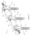
- FIG. 8illustrates an exemplary multi-level spinal fixation system 110 for stabilizing a portion of a spinal column utilizing the construct of FIGS. 7A and 7B .
- the spinal fixation system 110may include a first pedicle screw 12a configured to be secured to a first vertebra, a second pedicle screw 12b configured to be secured to a second vertebra, and a third pedicle screw 12c configured to be secured to a third vertebra, with the second pedicle screw 12b positioned between the first and third pedicle screws 12a, 12c
- the spinal fixation system 110may include additional pedicle screws 12 configured to be secured to additional vertebrae if desired.
- the spinal fixation system 110may include a support construct 22 positioned between the first and second pedicle screws 12a, 12b and between the second and third pedicle screws 12b, 12c
- a first spacer 24may be positioned between the first and second pedicle screws 12a, 12b and a second spacer 24 may be positioned between the second and third pedicle screws 12b, 12c
- a cord 30may extend through a bore of each of the spacers 24 and through the channel 15 of the housing 14. of each of the first, second and third pedicle screws 12a, 12b, 12c
- the portions of the cord 30 which are shown extending from the housings 14 of the pedicle screws 12a. 12cmay be trimmed as desired to reduce and/or eliminate the portion of the cord 30 extending from the pedicle screws 12a, 12c.
- the cord 30 of the spinal stabilization system 10may limit the range of flexion of the spinal segment, whereas the spacers 24 may limit the range of extension of the spinal segment.
- the cord 30may be placed in tension and the spacers 24 may be placed in compression between the pedicle screws 12a, 12b, 12c
- the spinal stabilization system 10may also include inserts 32 with a medial portion 38 positionable in the channels 15 of the pedicle screws 12 and first and second flanges 34, 36 located on opposing sides of the housing 14 of a pedicle screw 12. So arranged, end surfaces 48 of the inserts 32 may be configured to abut an end surface of a spacer 24, as described above.
- the insert 32may be positioned in the channel 15 in a top-loaded fashion in which the insert 32 is moved into the channel 15 of the housing 14 in a direction generally perpendicular to the longitudinal axis of the channel 15 of the housing 14.
- the open channel 40 of each of the inserts 32may be configured to receive the cord 30 therein.
- the open channel 40 of the inserts 32allows the cord 30 to be inserted into the open channel 40 of the inserts 32 in a direction generally perpendicular to the longitudinal axis of the open channel 40.
- the slots 39 in the first and second flanges 34, 36 of the inserts 32allow the cord 30 to be inserted into the open channel 40 while extending outward from the first and second flanges 34, 36.
- fasteners 20may be rotatably engaged with the housings 14 of the first and third pedicle screws 12a, 12c to lock the housings 14 of the first and third pedicle screws 12a, 12c from pivotal movement while clamping the cord 30 in the housings 14 of the poly-axial pedicle screws 12a, 12c through direct contact of the fastener 20 against the cord 30, as discussed above.
- itmay be desirable to lock the housing 14 of the second or intermediate pedicle screw 12b while allowing the cord 30 to freely move in an axial direction relative to the housing 14 of the second pedicle screw 12b.
- the fastener 120discussed above referring to FIGS.
- a fastener 20may be chosen to lock the housing 14 of the second pedicle screw 12b from pivotal movement while clamping the cord 30 in the housing 14 of the poly-axial pedicle screw 12b through direct contact of the fastener 20 against the cord 30, as discussed above.
Landscapes
- Health & Medical Sciences (AREA)
- Orthopedic Medicine & Surgery (AREA)
- Life Sciences & Earth Sciences (AREA)
- Neurology (AREA)
- Surgery (AREA)
- Heart & Thoracic Surgery (AREA)
- Engineering & Computer Science (AREA)
- Biomedical Technology (AREA)
- Nuclear Medicine, Radiotherapy & Molecular Imaging (AREA)
- Medical Informatics (AREA)
- Molecular Biology (AREA)
- Animal Behavior & Ethology (AREA)
- General Health & Medical Sciences (AREA)
- Public Health (AREA)
- Veterinary Medicine (AREA)
- Surgical Instruments (AREA)
Description
- The disclosure is directed to a vertebral stabilization system. More particularly, the disclosure is directed to a dynamic stabilization system including a support construct configured to be used with poly-axial pedicle screws.
- The spinal column of a patient includes a plurality of vertebrae linked to one another by facet joints and an intervertebral disc located between adjacent vertebrae. The facet joints and intervertebral disc allow one vertebra to move relative to an adjacent vertebra, providing the spinal column a range of motion. Diseased, degenerated, damaged, or otherwise impaired facet joints and/or intervertebral discs may cause the patient to experience pain or discomfort and/or loss of motion, thus prompting surgery to alleviate the pain and/or restore motion of the spinal column.
- One possible method of treating these conditions is to immobilize a portion of the spine to allow treatment. Traditionally, immobilization has been accomplished by rigid stabilization. For example, in a conventional spinal fusion procedure, a surgeon restores the alignment of the spine or the disc space between vertebrae by installing a rigid fixation rod between pedicle screws secured to adjacent vertebrae. Bone graft is placed between the vertebrae, and the fixation rod cooperates with the screws to immobilize the two vertebrae relative to each other so that the bone graft may fuse with the vertebrae.
- Dynamic stabilization has also been used in spinal treatment procedures. Dynamic stabilization does not result in complete immobilization, but instead permits a degree of mobility of the spine while also providing sufficient support and stabilization to effect treatment. One example of a dynamic stabilization system is the Dynesys® system available from Zimmer Spine, Inc. of Minneapolis, MN. Such dynamic stabilization systems typically include a flexible member positioned between pedicle screws installed in adjacent vertebrae of the spine. A flexible cord can be threaded through the bore in the flexible member and secured to the pedicle screws while cooperating with the flexible member to permit mobility of the spine. The pedicle screw currently used iri the Dynesys® system is a mono-axial pedicle screw which may present limitations during installation of the Dynesys® system in some instances.
EP1970018A2 describes a spinal stabilization system including at least two anchors having a bone attachment portion and a head portion and a flexible assembly coupled to the anchors, the flexible assembly comprising a flexible cord with connectors slideably mounted to the cord and spacers slideably mounted to the cord between the connectors, where each connector couples with a head portion of an anchor.- There is an ongoing need to provide alternative devices, assemblies and systems that can function to alleviate pain or discomfort, provide stability, such as dynamic stability, and/or restore a range of motion to a spinal segment of a spinal column.
- One illustrative embodiment is a spinal stabilization system comprising a polyaxial pedicle screw including a housing and a threaded shaft extending from the housing, the threaded shaft pivotable relative to the housing to a plurality of angular positions, the housing including a channel extending from a first side of the housing to a second side of the housing; a support construct including a spacer and a cord extendable through a lumen of the spacer; and a fastener configured to rotatably engage the housing of the polyaxial pedicle screw, characterized by: an insert positionable in the channel of the housing, the insert including an open channel extending from a first end of the insert to a second end of the insert: wherein the cord is positionable in the open channel of the insert such that a first portion of the cord extends from the first side of the housing of the polyaxial pedicle screw and a second portion of the cord extends from the second side of the housing of the polyaxial pedicle screw; and wherein rotationable engagement of the fastener with the housing causes the fastener to directly contact the cord to exert a clamping force directly on the cord.
- Another illustrative embodiment is a spinal stabilization system including a polyaxial pedicle screw, a spool, a spacer, a flexible cord, and a fastener. The polyaxial pedicle screw includes a housing pivotably coupled to a threaded shaft. The housing includes a channel extending from a first side of the housing to a second side of the housing. The spool includes a first flange, a second flange and a medial portion extending between the first flange and the second flange. The spool is configured to engage the housing of the pedicle screw such that the medial portion is positioned in the channel with the first flange positioned adjacent the first side of the housing and the second flange positioned adjacent the second side of the housing. The spacer has a first end, a second end and a lumen extending through the spacer from the first end to the second end. The first end of the spacer is positionable in abutting contact with the first flange of the spool. The flexible cord is configured to extend through the lumen of the spacer and through the spool such that a first portion of the flexible cord extends from the first flange of the spool and a second portion of the flexible cord extends from the second flange of the spool. The fastener is configured to rotatably engage the housing of the pedicle screw to directly contact and press against the cord such that the cord is compressed between the fastener and a surface of the spool.
- The invention will now be further described by way of example with reference to the accompanying drawings, in which:
FIG. 1 is a perspective view of an exemplary spinal stabilization system;FIG. 2 is a perspective view of a pedicle screw assembly of the spinal stabilization system ofFIG. 1 , including an insert positioned in a the channel of the housing of the pedicle screw,FIG. 3 is an exploded view of the pedicle screw assembly ofFIG 2 ;FIG. 4 is a perspective view of the insert of the pedicle screw assembly ofFIG 2 ;FIG. 4A is a top view of the insert shown inFIG. 4 ;FIG. 4B is a longitudinal cross-sectional view of the insert shown inFIG. 4 ;FIGS. 5A and5B illustrate one exemplary configuration for locking the housing of a poly-axial pedicle screw from pivotal movement while clamping a cord to the pedicle screw;FIGS. 6A and6B illustrate another exemplary configuration for locking the housing of a poly-axial pedicle screw from pivotal movement while clamping a cord to the pedicle screw: andFIGS. 7A and7B illustrate an exemplary configuration for locking the housing of a poly-axial pedicle screw from pivotal movement while capturing a cord in the housing of the pedicle screw;FIG. 8 is a perspective view of another exemplary spinal stabilization system.- For the following defined terms, these definitions shall be applied, unless a different definition is given in the claims or elsewhere in this specification.
- All numeric values are herein assumed to be modified by the term "about", whether or not explicitly indicated The term "about" generally refers to a range of numbers that one of skill in the art would consider equivalent to the recited value (i e., having the same function or result). In many instances, the term "about" may be indicative as including numbers that are rounded to the nearest significant figure.
- The recitation of numerical ranges by endpoints includes all numbers within that range (e.g. ; 1 to 5 includes 1.1.5. 2. 2.75. 3, 3.80, 4. and 5).
- Although some suitable dimensions ranges and/or values pertaining to various components, features and/or specifications are disclosed, one of skill in the art, incited by the present disclosure, would understand desired dimensions, ranges and/or values may deviate from those expressly disclosed.
- As used in this specification and the appended claims, the singular forms "a". "an", and "the" include plural referents unless the content clearly dictates otherwise. As used in this specification and the appended claims, the term "or" is generally employed in its sense including "and/or" unless the content clearly dictates otherwise.
- The following detailed description should be read with reference to the drawings in which similar elements in different drawings are numbered the same. The detailed description and the drawings, which are not necessarily to scale, depict illustrative embodiments which are intended only as exemplary. Selected features of any illustrative embodiment may be incorporated into an additional embodiment unless clearly stated to the contrary.
- Referring now to
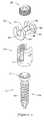
FIG. 1 , there is shown aspinal fixation system 10 for stabilizing a portion of a spinal column, such as one or more spinal segments of a spinal column, As used herein, a spinal segment is intended to refer to two or more vertebrae, the intervertebral disc(s) between the vertebrae and other anatomical elements between the vertebrae. For example, a spinal segment may include first and second adjacent vertebrae and the intervertebral disc located between the first and second vertebrae. Thespinal stabilization system 10 may provide dynamic stabilization to a spinal segment, preserving and/or allowing for a range of motion of the spinal segment. - In some embodiments, the
spinal stabilization system 10 may be used to treat discogenic low back pain, degenerative spinal stenosis, disc herniations, facet syndrome, posterior element instability, adjacent level syndrome associated with spinal fusion, and/or other maladies associated with the spinal column. - The
spinal stabilization system 10 may include one or more or a plurality of vertebral anchors, depicted aspedicle screws 12. However, in some embodiments the vertebral anchors may be vertebral hooks (e.g., laminar hooks) or other types of fastening members for attachment to a bony structure such as a vertebra of the spinal column. Each of thepedicle screws 12 may be configured to be secured to a vertebra, of a spinal column, For instance, thefirst pedicle screw 12a may be secured to a first vertebra and thesecond pedicle screw 12b may be secured to a second vertebra.Additional pedicle screws 12 may be present in instances in which thespinal stabilization system 10 spans three or more vertebra of the spinal column. - The
pedicle screw 12 may include ahousing 14 and ashaft 16, which may includethreads 18, extending from thehousing 14. Thehousing 14 may include a channel such as a U-shaped channel extending from one side of thehousing 14 to an opposite second side of thehousing 14. Thechannel 15 may be defined between opposing legs of thehousing 14. Theshaft 16 may be configured to be instated into a bony region of a vertebra of the spinal column, For example, theshaft 16 may be installed into a pedicle of a vertebra, or other region of a vertebra. Theshaft 16 may extend along a longitudinal axis. Thepedicle screw 12 depicted in the Figures is a poly-axial pedicle screw which allows thehousing 14 to be pivotable relative to theshaft 16 to a plurality of angular positions relative to the longitudinal axis. Thepedicle screw 12, as shown inFIG. 3 , may include ahead portion 17 at the end of theshaft 16 which is received in thehousing 14. Thehousing 14 may be pivotable relative to thehead portion 17 of theshaft 16. - The
pedicle screw 12 may include a securing element, such as a threaded fastener 20 (e.g.. a set screw, cap) configured to rotatably engage thehousing 14 to secure a portion of asupport construct 22 to thepedicle screw 12. For example, the threadedfastener 20 may include threads which mate with threads formed in thehousing 14 In other embodiments, thefastener 20 may include one or more flanges, cam surfaces, or other engagement features that engage with one or more channels grooves, surfaces, or other engagement features of thehousing 14 through rotation of thefastener 20. Thefastener 20 may be rotatably engaged between spaced apart legs of thehousing 14 which define thechannel 15 of thehousing 14 therebetween. - The
spinal stabilization system 10 may also include one or more, or a plurality of support constructs 22 extending between pedicle screws 12 of thespinal stabilization system 10. As an illustrative example, thespinal stabilization system 10 shown inFIG. 1 includes asupport construct 22 extending between thefirst pedicle screw 12a and thesecond pedicle screw 12b. - The support construct 22 may be constructed of a plurality of components in some instances. For instance, the support construct 22 may include a
spacer 24, and a flexible member such as aflexible cord 30 extending through thespacer 24, as weir as other components if desired. - In some embodiments, the
spacer 24 may be an annular spacer having a lumen (not shown) extending from aend 26 to asecond end 28 of thespacer 24. For example, in some embodiments thespacer 24 may be a cylindrical member having a lumen extending therethrough. In other embodiments, thespacer 24 may be molded, extruded, or otherwise formed over and/or around thecord 30. Thespacer 24 may be positioned between thehousing 14 of thefirst pedicle screw 12a and thehousing 14 of thesecond pedicle screw 12b. In some embodiments, thespacer 24 may be formed from polycarbonate urethane (PCU), although it will be recognized that various other materials suitable for implantation within the human body and for providing stabilization of the spine white maintaining flexibility may be used. In other embodiments, thespacer 24 can be constructed of other materials such as metal, polymeric materials, or combinations of materials. - The
cord 30 may extend from thehousing 14 of thefirst pedicle screw 12a to thehousing 14 of thesecond pedicle screw 12b. In one embodiment, thecord 30 may be formed from polyethylene-terephthalate (PET), although it will be recognized that various other materials suitable for implantation within the human body and for providing stabilization of the spine while maintaining flexibility may be used. In other embodiments, thecord 30 can be constructed of other flexible materials such as metal, polymeric materials, or combinations of flexible materials. It is noted that during a medical procedure the portions of thecord 30 which are shown extending from the channels of thepedicle screws cord 30 extending from thepedicle screws - When implanted in a patient, the
cord 30 of thespinal stabilization system 10 may limit the range of flexion of the spinal segment, whereas thespacer 24 may limit the range of extension of the spinal segment. For instance, thecord 30 may be placed in tension and thespacer 24 may be placed in compression between thepedicle screws - The
spinal stabilization system 10 may also includeinserts 32 configured to be inserted into the channels of thehousing 14 of the pedicle screws 12. One possible embodiment of theinsert 32 is further illustrated inFIG. 4 . Theinserts 32, which may be considered spools in some instances, may include afirst flange 34 proximate a first end of theinsert 32, asecond flange 36 proximate the second end of theinsert 32, and amedial portion 38 intermediate thefirst flange 34 and thesecond flange 36 and extending therebetween. Theinsert 32 may haveend surfaces 48 configured to abut an end surface of thespacer 24. For instance, when assembled anend surface 48 of aninsert 32 coupled with thefirst pedicle screw 12a may abut an end surface of thespacer 24 proximate thefirst end 26 of thespacer 24 and anend surface 48 of aninsert 32 coupled with thesecond pedicle screw 12b may abut an end surface of thespacer 24 proximate thesecond end 28 of thespacer 24. - As shown in
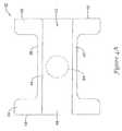
FIG. 2 , theinsert 32 may be configured such that themedial portion 38 is positionable in the channel 15 (shown inFIG. 3 ) of thehousing 14 of thepedicle screw 12 with thefirst flange 34 positioned exterior of thehousing 14 and facing the first side of thehousing 14 and thesecond flange 36 positioned exterior of thehousing 14 and facing the second side of thehousing 14. Theinsert 32 may be positioned in thechannel 15 in a top-loaded fashion in which theinsert 32 is moved into thechannel 15 of thehousing 14 in a direction generally perpendicular to the longitudinal axis of thechannel 15 of thehousing 14. - The
insert 32 may include anopen channel 40 extending from the first end of theinsert 32 to the second end of theinsert 32 along a axis parallel to the longitudinal axis of thechannel 15 through thehousing 14. As used herein the term "open channel" is intended to refer to a conduit which is not enclosed by a peripheral surface extending entirely around a periphery of the conduit. In other words, theopen channel 40 may be open to the exterior of theinsert 32 along at least a portion of its length in addition to being open at its ends such theopen channel 40 is open laterally from the longitudinal axis of theopen channel 40. In some instances, theopen channel 40 may otherwise be referred to as a furrow, recess or depression extending from the first end of theinsert 32 to the second end of theinsert 32. - The
open channel 40 may be configured to receive thecord 30 therein. For instance, theopen channel 40 allows thecord 30 to be inserted into theopen channel 40 of theinsert 32 in a direction generally perpendicular to the longitudinal axis of theopen channel 40. Each of thefirst flange 34 and thesecond flange 36 may include aslot 39 extending from a periphery of theflange open channel 40 to allow thecord 30 to be inserted into theopen channel 40 white extending outward from the first andsecond flanges - The
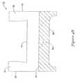
open channel 40 may be defined as a recessed area of theinsert 32 between afirst edge 42 and asecond edge 44 of theinsert 32. The first andsecond edges open channel 40 and/or themedial portion 38 of theinsert 32. In some instances, the first andsecond edges open channel 40. In some embodiments, theopen channel 40 may include asurface 46, such as a concave surface, extending between the first andsecond edges cord 30 thereagainst. When implanted, thecord 30 may be compressed between thefastener 20 and thesurface 46 of theinsert 32. - In some instances, the
surface 46 may include any mechanical gripping means such as, but not limited to, one or more threads, ribs, projecting grooves, teeth, posts, spikes, and/or serrations or combination thereof. The mechanical gripping means may increase the purchase of thecord 30 between thefastener 20 and theinsert 32 as will be further described herein. Additionally or alternatively, theinsert 32 may include adepression 54 extending into theinsert 32 from the base of theconcave surface 46 of theopen channel 40. Oneexemplary depression 54 is shown in dashed lines inFIGS. 4A and4B as a spherically concave depression which may be axially aligned with the axis of rotation of thefastener 20 when theinsert 32 is positioned in thechannel 15 of thehousing 14. - The presence of the
depression 54 may advantageously enhance the securement of thecord 30 between thefastener 20 and theinsert 32. For instance, when thecord 30 is compressed by thefastener 20, a portion of thecord 30 may be pressed into thedepression 54, providing a more tortuous pathway for thecord 30 passing through theopen channel 40, as shown herein atFIG. 5B . Although thedepression 54 is shown with regard to the configuration ofFIGS. 5A and5B , in some instances thedepression 54 may not be present. Furthermore, thedepression 54, while not illustrated regarding the configuration ofFIGS. 6A and6B , may be included in such a configuration, if desired. - The presence of the
insert 32 in thechannel 15 of thehousing 14 may facilitate locking thehousing 14 from poly-axial movement relative to theshaft 16 of thepedicle screw 12 when thespinal stabilization system 10 is installed, For instance a locking force exerted by thefastener 20 may be transmitted through theinsert 32 to thehead portion 17 of theshaft 16 to lock thehousing 14 from pivotable movement relative to thehead portion 17 of theshaft 16. Theinsert 32, which is more rigid than thecord 30, is in direct contact with thehead portion 17 of theshaft 16 to transfer the locking force exerted by thefastener 20 to thehead portion 17. - One exemplary configuration for locking the
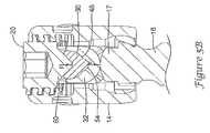
housing 14 of the poly-axial pedicle screw 12 from pivotal movement while clamping thecord 30 to thepedicle screw 12 is shown inFIGS. 5A and5B . - As shown in
FIG. 5A , theinsert 32 may be inserted into thechannel 15 of thehousing 14 in a direction generally to the longitudinal axis of theopen channel 40. Thecord 30 may also be inserted into thechannel 15 of thehousing 14 and into theopen channel 40 of theinsert 32 such that thecord 30 rests against the recessedsurface 46 of theinsert 32. Thus, themedial portion 38 of theinsert 32 may be positioned between thehead portion 17 of theshaft 16 of thepedicle screw 12 and thecord 30. - The
fastener 20 may then be engaged with thehousing 14, such as through rotational movement of thefastener 20 relative to thehousing 14. in some instances, thefastener 20 may include a threaded portion which threadably engages a threaded portion of thehousing 14, such as internally threaded portions of opposing legs of thehousing 14 defining thechannel 15. Rotational movement of thefastener 20 moves thefastener 20 into engagement with thecord 30. As shown inFIG. 5A , thefastener 20 may include aprojection 50, such as a contest or frusta-conical tip, configured to press against and/or penetrate into thecord 30. - As shown in
FIG. 5B , rotational engagement of thefastener 20 with thehousing 14 causes thefastener 20 to directly contact thecord 30 to exert a clamping force F directly on thecord 30 to compress thecord 30 between thefastener 20 and theinsert 32. The amount of rotation of thefastener 20, and axial movement of thefastener 20 along its axis of rotation, controls the magnitude of the clamping force F exerted on the cord 30 (i.e., the greater the amount of rotation of thefastener 20 results in a greater clamping force F). Deformation of thecord 30 and/or penetration into thecord 30 by theprojection 50 may prevent thecord 30 from moving axially from thehousing 14. Furthermore, as shown inFIG. 5B , if adepression 54 is present in the base of theopen channel 40 of theinsert 32, the compression of thecord 30 by thefastener 20 may displace a portion of thecord 30 into thedepression 54 creating a more tortuous pathway for thecord 30 along theopen channel 40. The clamping force F exerted onto thecord 30 is transferred through thecord 30 to theinsert 32 and through theinsert 32 to thehead portion 17 of theshaft 16 of thepedicle screw 12. - When the clamping force F is sufficiently large, the clamping force F exerted onto the
head portion 17 by theinsert 32 jocks thehousing 14 from pivotal movement relative to thehead portion 17. The rigid interface between theinsert 32 and thehead portion 17 of theshaft 16 enhances the locking effect of thehousing 14 over a configuration in which thecord 30 directly exerts a force against thehead portion 17. Thus, the clamping force F generated through rotational engagement of thefastener 20 with thehousing 14 both clamps thecord 30 to the insert 32 (and thus secures thecord 30 to the pedicle scrow 12) and locks thehousing 14 from pivotal movement relative to theshaft 16 of thepedicle screw 12. - Another exemplary configuration for locking the
housing 14 of the poly-axil pedicle screw 12 from pivotal movement while clamping thecord 30 to thepedicle screw 12 is shown inFIGS, 6A and6B . - As shown in
FIG. 6A , theinsert 32 may be inserted into thechannel 15 of thehousing 14 in a direction generally perpendicular to the longitudinal axis of theopen channel 40. Thecord 30 may also be inserted into thechannel 15 of thehousing 14 and into theopen channel 40 of theinsert 32 such that thecord 30 rests against the recessedsurface 46 of theinsert 32. Thus, themedial portion 38 of theinsert 32 may be positioned between thehead portion 17 of theshaft 16 of thepedicle screw 12 and thecord 30. - The
fastener 20 may then be engaged with thehousing 14, such as through rotational movement of thefastener 20 relative to thehousing 14. In some instances, thefastener 20 may include a threaded portion which threadably engages a threaded portion of thehousing 14. Rotational movement of thefastener 20 moves thefastener 20 into engagement with thecord 30. As shown inFIG. 6A , thefastener 20 may include aprojection 50, such as a conical or tip, configured to press against and/or penetrate into thecord 30 Thefastener 20 may also include arim 52 configured to come into contact with theupper edges insert 32. - As shown in
FIG. 6B , rotational engagement of thefastener 20 with the housing 14 a first rotational amount causes thefastener 20 to directly contact thecord 30 to exert a clamping force F1 directly on thecord 30 to compress thecord 30 between thefastener 20 and theinsert 32 The amount of rotation of thefastener 20 up to a threshold amount, and thus axial movement of thefastener 20 along its axis of rotation up to a threshold amount, controls the magnitude of the clamping force F1 exerted on the cord 30 (i.e., the greater the amount of rotation of thefastener 20 up to a threshold amount results in a greater clamping force F1). Deformation of thecord 30 and/or penetration into thecord 30 by theprojection 50 may prevent thecord 30 from moving axially from thehousing 14 The clamping force F1 exerted onto thecord 30 is also transferred through thecord 30 to theinsert 32 and through theinsert 32 to thehead portion 17 of theshaft 16 of thepedicle screw 12. Until therim 52 of thefastener 20 contacts theedges insert 32, the locking force F3 exerted by theinsert 32 onto thehead portion 17 of theshaft 16 is approximately equal to the clamping force F1 exerted onto thecord 30 by thefastener 20 - The
fastener 20 may be rotatably engaged with the housing 14 a first rotational amount such that therim 52 of thefastener 20 comes into contact with theedges medial portion 38 of theinsert 32. Further rotation of thefastener 20 beyond this first rotational amount does not increase the compressive force F1 exerted on thecord 30 as the distance between thefastener 20 and thesurface 46 of theinsert 32 does not change once therim 52 comes into contact with theedges rim 52 of thefastener 20 contacts theedges insert 32 the clamping force F1 reaches its maximum threshold amount. The assembly may be sized and configured such that thecord 30 may be compressed between thefastener 20 and thesurface 46 of the insert 32 a predetermined amount such that the threshold amount of the clamping force F1 is sufficient to clamp thecord 30 to theinsert 32, and thus secure thecord 30 to thepedicle screw 12 while not letting thecord 30 move longitudinal through theopen channel 40 of theinsert 32. - Until the
rim 52 of thefastener 20 contacts theedges head portion 17 of theshaft 16 may be approximately equal to the clamping force F1 exerted directly on thecord 30 by thefastener 20. Once therim 52 of thefastener 20 contacts theedges edges insert 32, without further increasing the compression of thecord 30 beyond the predetermined amount. Thus, further rotation of thefastener 20 beyond the threshold amount, further increases the locking force F3 exerted on thehead portion 17 of theshaft 16 of thepedicle screw 12. The locking force F3 generated beyond this threshold amount of rotational engagement between thefastener 20 and thehousing 14 is approximately equal to the clamping force F1 exerted on thecord 30 from thefastener 20 plus the clamping force F2 exerted on theinsert 32 from thefastener 20. - When the locking force F3 is sufficiently large, the locking force F3 exerted onto the
head portion 17 by theinsert 32 locks thehousing 14 from pivotal movement relative to thehead portion 17. The rigid interface between theinsert 32 and thehead portion 17 of theshaft 16 enhances the locking effect of thehousing 14 over a configuration in which thecord 30 directly exerts a force against thehead portion 17 Thus, the clamping forces F1, F2 generated through rotational engagement of thefastener 20 with thehousing 14 both clamps thecord 30 to the insert 32 (and thus secures thecord 30 to the pedicle screw 12) and locks thehousing 14 from pivotal movement relative to theshaft 16 of thepedicle screw 12. - Thus, the
insert 32 of the disclosedspinal stabilization system 10 allows for locking thehousing 14 of a poly-axial pedicle screw 12 from pivotal movement while clamping thecord 30 in thehousing 14 of the poly-axial pedicle screw 12 through direct contact of thefastener 20 against thecord 30. The rigid interface between theinsert 32 and thehead portion 17 of theshaft 16 enhances the locking effect of thehousing 14 over a configuration in which thecord 30 directly exerts a force against thehead portion 17 of theshaft 16 of thepedicle screw 12. FIGS. 7A and7B illustrate an exemplary configuration for locking thehousing 14 of the poly-axial pedicle screw 12 from pivotal movement while capturing thecord 30 in thechannel 15 of thehousing 14 of thepedicle screw 12, In this configuration, thecord 30. While captured in thehousing 14, is permitted to move longitudinally relative to thehousing 14 and insert 32 since a clamping force is not applied to thecord 30.- As shown in
FIG. 7A , theinsert 32 may be inserted into thechannel 15 of thehousing 14 in a direction generally perpendicular to the longitudinal axis of theopen channel 40. Thecord 30 may also be inserted into thechannel 15 of thehousing 14 and into theopen channel 40 of theinsert 32 such that thecord 30 rests against the recessedsurface 46 of theinsert 32. Thus, themedial portion 38 of theinsert 32 may be positioned between thehead portion 17 of theshaft 16 of thepedicle screw 12 and thecord 30. - A
fastener 120 may then be engaged with thehousing 14, to capture thecord 30 in thechannel 15 of thehousing 14 without applying a clamping force onto thecord 30. For instance, thefastener 120 may include a first,upper component 130 rotatably coupled to a second,lower component 150. For example, thefastener 120 may include an upper threaded screw portion rotatably coupled to a lower, saddle portion. The thread screw portion (upper component 130) may be rotated relative to the saddle portion (lower component 150) about an axis of rotation. The threaded screw portion may threadedly engage with a threaded portion of thehousing 14 through rotational movement of the threaded screw portion relative to thehousing 14 while the saddle portion remains in a stationary orientation relative to thehousing 14. In other instances, theupper component 130 of thefastener 120 may include other engagement features, such as one or more flanges, cam surfaces, etc., for rotatably engaging an engagement portion of thehousing 14. Rotational movement of theupper component 130 of thefastener 120 moves thefastener 120 into engagement with theinsert 32 while capturing thecord 30 between thelower component 150 of thefastener 120 and thesurface 46 of theinsert 32. - The
lower component 150 may be rotatably attached to theupper component 130 with aboss 140 that extends into an opening in theupper component 130. Thelower component 150 of thefastener 120 may include alower edge 152 configured to come into contact with the upper edges 42. 44 of theinsert 32, while aconcave cavity 151 formed in thelower edge 152 receives thecord 30 therein. Theconcave cavity 151, in combination with theopen channel 40 of theinsert 32, together form a through bore through the construct, allowing thecord 30 to freely move in an axial direction relative to thehousing 14 of thepedicle screw 12. - As shown in
FIG. 7B , rotational engagement of theupper component 130 of thefastener 120 with thehousing 14 causes thelower edge 152 of thelower component 150 of thefastener 120 to come into contact with theedges medial portion 38 of theinsert 32, thereby exerting a locking force F on theinsert 32. The assembly may be sized and configured such that thecord 30 is not compressed between thefastener 20 and thesurface 46 of theinsert 32 when a clamping force F is exerted onto theinsert 32 by thefastener 20, and thus allowing thecord 30 to move longitudinally through the bore collectively defined by theconcave cavity 151 and theopen channel 40 of theinsert 32. Further rotation of theupper component 130 of thefastener 120 further increases the locking force F exerted on thehead portion 17 of theshaft 16 of thepedicle screw 12 without applying a compressive force to thecord 30. When the locking force F is sufficiently large, the locking force F exerted onto thehead portion 17 by theinsert 32 locks thehousing 14 from pivotal movement relative to thehead portion 17. Thus, the clamping force F generated through rotational engagement of theupper component 130 of thefastener 20 with thehousing 14 locks thehousing 14 from pivotal movement relative to theshaft 16 of thepedicle screw 12 while continuing to permit axial movement of thecord 30 through thechannel 15 of thehousing 14. FIG. 8 illustrates an exemplary multi-levelspinal fixation system 110 for stabilizing a portion of a spinal column utilizing the construct ofFIGS. 7A and7B . Thespinal fixation system 110 may include afirst pedicle screw 12a configured to be secured to a first vertebra, asecond pedicle screw 12b configured to be secured to a second vertebra, and a third pedicle screw 12c configured to be secured to a third vertebra, with thesecond pedicle screw 12b positioned between the first andthird pedicle screws 12a, 12c Thespinal fixation system 110 may include additional pedicle screws 12 configured to be secured to additional vertebrae if desired.- The
spinal fixation system 110 may include asupport construct 22 positioned between the first andsecond pedicle screws first spacer 24 may be positioned between the first andsecond pedicle screws second spacer 24 may be positioned between the second and third pedicle screws 12b, 12c, Acord 30 may extend through a bore of each of thespacers 24 and through thechannel 15 of thehousing 14. of each of the first, second andthird pedicle screws - It is noted that during a medical procedure the portions of the
cord 30 which are shown extending from thehousings 14 of thepedicle screws 12a. 12c may be trimmed as desired to reduce and/or eliminate the portion of thecord 30 extending from thepedicle screws 12a, 12c. - When implanted in a patient, the
cord 30 of thespinal stabilization system 10 may limit the range of flexion of the spinal segment, whereas thespacers 24 may limit the range of extension of the spinal segment. For instance, thecord 30 may be placed in tension and thespacers 24 may be placed in compression between thepedicle screws - The
spinal stabilization system 10 may also includeinserts 32 with amedial portion 38 positionable in thechannels 15 of the pedicle screws 12 and first andsecond flanges housing 14 of apedicle screw 12. So arranged, end surfaces 48 of theinserts 32 may be configured to abut an end surface of aspacer 24, as described above. Theinsert 32 may be positioned in thechannel 15 in a top-loaded fashion in which theinsert 32 is moved into thechannel 15 of thehousing 14 in a direction generally perpendicular to the longitudinal axis of thechannel 15 of thehousing 14. - The
open channel 40 of each of theinserts 32 may be configured to receive thecord 30 therein. For instance, theopen channel 40 of theinserts 32 allows thecord 30 to be inserted into theopen channel 40 of theinserts 32 in a direction generally perpendicular to the longitudinal axis of theopen channel 40. Theslots 39 in the first andsecond flanges inserts 32 allow thecord 30 to be inserted into theopen channel 40 while extending outward from the first andsecond flanges - As shown in
FIG. 8 ,fasteners 20 may be rotatably engaged with thehousings 14 of the first andthird pedicle screws 12a, 12c to lock thehousings 14 of the first andthird pedicle screws 12a, 12c from pivotal movement while clamping thecord 30 in thehousings 14 of the poly-axial pedicle screws 12a, 12c through direct contact of thefastener 20 against thecord 30, as discussed above. However, it may be desirable to lock thehousing 14 of the second orintermediate pedicle screw 12b while allowing thecord 30 to freely move in an axial direction relative to thehousing 14 of thesecond pedicle screw 12b. In such an instance, thefastener 120, discussed above referring toFIGS. 7A and7B , may be rotatably engaged with thehousing 14 of thesecond pedicle screw 12b to achieve this result. As described above, rotation of theupper component 130 of thefastener 120 locks thehousing 14 from pivotal movement relative to theshaft 16 of thepedicle screw 12b while continuing to permit axial movement of thecord 30 through thechannel 15 of thehousing 14. - In other embodiments, it may be desirable to have the
cord 30 clamped in thehousing 14 of thesecond pedicle screw 12b. In such an instance, afastener 20 may be chosen to lock thehousing 14 of thesecond pedicle screw 12b from pivotal movement while clamping thecord 30 in thehousing 14 of the poly-axial pedicle screw 12b through direct contact of thefastener 20 against thecord 30, as discussed above. - Those skilled in the art will recognize that the present invention may be manifested In a variety of forms other than the specific embodiments described and contemplated herein.
Claims (17)
- A spinal stabilization system (10, 110) comprising:a polyaxial pedicle screw (12) including a housing (14) and a threaded shaft (16) extending from the housing (14), the threaded shaft (16) pivotable relative to the housing (14) to a plurality of angular positions, the housing (14) including a channel (15) extending from a first side of the housing (14) to a second side of the housing (14);a support construct (22) including a spacer (24) and a cord (30) extendable through a lumen of the spacer (24) ; anda fastener (20, 120) configured to rotatably engage the housing (14) of the polyaxial pedicle screw (12),characterized by:an insert (32) positionable in the channel (15) of the housing (14), the insert (32) including an open channel (40) extending from a first end of the insert (32) to a second end of the insert (32);wherein the cord (30) is positionable in the open channel (40) of the insert (32) such that a first portion of the cord (30) extends from the first side of the housing (14) of the polyaxial pedicle screw (12) and a second portion of the cord (30) extends from the second side of the housing (14) of the polyaxial pedicle screw (12); andwherein rotational engagement of the fastener (20, 120) with the housing (14) causes the fastener (20, 120) to directly contact the cord (30) to exert a clamping force directly on the cord (30).
- The spinal stabilization system of claim 1, wherein the open channel (40) is defined as a recessed area between a first edge (42) of the insert (32) and a second edge (44) of the insert (32).
- The spinal stabilization system of claim 2, wherein rotational engagement of the fastener (20, 120) with the housing (14) causes the fastener (20, 120) to directly contact the first (42) and second (44) edges of the insert (32) once the cord (30) has been compressed between the fastener (20, 120) and the insert (32) a predetermined amount.
- The spinal stabilization system of claim 3, wherein further rotational engagement of the fastener (20, 120) with the housing (14) does not increase compression of the cord (30) between the fastener (20, 120) and the insert (32) beyond the predetermined amount.
- The spinal stabilization system of claim 3, wherein rotational engagement of the fastener (20, 120) with the housing (14) exerts a locking force against a head (17) of the threaded shaft (16) to lock the housing (14) from pivotal movement relative to the threaded shaft (16).
- The spinal stabilization system of claim 3, wherein the insert (32) is configured such that when the fastener (20, 120) directly contacts the first (42) and second (44) edges of the insert (32), the fastener (20, 120) is prevented from further compressing the cord (30).
- The spinal stabilization system of any preceding claim, wherein the insert (32) includes a first flange (34) proximate the first end of the insert (32), a second flange (36) proximate the second end of the insert (32), and a medial portion (38) extending between the first flange (34) and the second flange (36), the first flange (34) positionable exterior of the housing (14) and facing the first side of the housing (14) and the second flange (36) positionable exterior of the housing (14) and facing the second side of the housing (14).
- The spinal stabilization system of claim 7, wherein the first flange (34) includes a slot (39) extending from the open channel (40) to a peripheral edge of the first flange (34) and the second flange (36) includes a slot (39) extending ;from the open channel (40) to a peripheral edge of the second flange (36), such that the cord (30) can be positioned in the open channel (40) through movement of the cord (30) in a direction perpendicular to a longitudinal axis of the open channel (40).
- The spinal stabilization system of claim 8, wherein the open channel (40) of the insert (32) includes a concave surface (46) extending between a first upper edge (42) of the open channel (40) and a second upper edge (44) of the open channel (40).
- The spinal stabilization system of claim 9, wherein the insert (32) includes a depression (54), preferably a spherically concave depression (54), extending into the insert (32) from the concave surface (46) into which a portion of the cord (30) is depressed into to provide a more tortuous pathway for the cord (30) passing through the open channel (40).
- The spinal stabilization system of claim 9 or 10, wherein the fastener (20, 120) includes a projection (50) configured to press against or penetrate into the cord (30).
- The spinal stabilization system of any preceding claim, wherein the fastener (20, 120) directly contacts and exerts a clamping force directly on a medial portion (38) of the insert (32) to lock the housing (14) from pivotal movement relative to the threaded shaft (16).
- The spinal stabilization system of claim 12, wherein the fastener (20, 120) only directly contacts the medial portion (38) of the insert (32) and exerts the clamping force directly on the medial portion (38) of the insert (32) once the cord (30) has been compressed between the fastener (20, 120) and the insert (32) a predetermined amount.
- The spinal stabilization system of claim 13, wherein further rotation of the fastener (20, 120) increases the clamping force exerted directly on the medial portion (38) of the insert (32) but does not appreciably increase the compressive force exerted on the cord (30).
- The spinal stabilization system of any preceding claim, wherein a force exerted on the cord (30) by the fastener (20, 120) is transferred through the insert (32) to lock the housing (14) from pivotal movement relative to the threaded shaft (16) of the polyaxial pedicle screw (12).
- The spinal stabilization system of any preceding claim, wherein the open channel (40) is open laterally from a longitudinal axis of the open channel (40).
- The spinal stabilization system of any preceding claim, wherein the insert (32) directly contacts a head portion (17) of the threaded shaft (16) to lock the housing (14) from pivotable movement relative to the head portion (17).
Applications Claiming Priority (1)
| Application Number | Priority Date | Filing Date | Title |
|---|---|---|---|
| US12/755,520US8740945B2 (en) | 2010-04-07 | 2010-04-07 | Dynamic stabilization system using polyaxial screws |
Publications (2)
| Publication Number | Publication Date |
|---|---|
| EP2374424A1 EP2374424A1 (en) | 2011-10-12 |
| EP2374424B1true EP2374424B1 (en) | 2014-05-07 |
Family
ID=44356218
Family Applications (1)
| Application Number | Title | Priority Date | Filing Date |
|---|---|---|---|
| EP11161378.2ANot-in-forceEP2374424B1 (en) | 2010-04-07 | 2011-04-06 | Dynamic stabilization system using polyaxial screws |
Country Status (2)
| Country | Link |
|---|---|
| US (1) | US8740945B2 (en) |
| EP (1) | EP2374424B1 (en) |
Families Citing this family (41)
| Publication number | Priority date | Publication date | Assignee | Title |
|---|---|---|---|---|
| US7833250B2 (en) | 2004-11-10 | 2010-11-16 | Jackson Roger P | Polyaxial bone screw with helically wound capture connection |
| US8876868B2 (en) | 2002-09-06 | 2014-11-04 | Roger P. Jackson | Helical guide and advancement flange with radially loaded lip |
| US7377923B2 (en) | 2003-05-22 | 2008-05-27 | Alphatec Spine, Inc. | Variable angle spinal screw assembly |
| US7766915B2 (en) | 2004-02-27 | 2010-08-03 | Jackson Roger P | Dynamic fixation assemblies with inner core and outer coil-like member |
| US8926670B2 (en) | 2003-06-18 | 2015-01-06 | Roger P. Jackson | Polyaxial bone screw assembly |
| US7776067B2 (en) | 2005-05-27 | 2010-08-17 | Jackson Roger P | Polyaxial bone screw with shank articulation pressure insert and method |
| US8926672B2 (en) | 2004-11-10 | 2015-01-06 | Roger P. Jackson | Splay control closure for open bone anchor |
| US9216041B2 (en)* | 2009-06-15 | 2015-12-22 | Roger P. Jackson | Spinal connecting members with tensioned cords and rigid sleeves for engaging compression inserts |
| US9980753B2 (en) | 2009-06-15 | 2018-05-29 | Roger P Jackson | pivotal anchor with snap-in-place insert having rotation blocking extensions |
| US9168069B2 (en) | 2009-06-15 | 2015-10-27 | Roger P. Jackson | Polyaxial bone anchor with pop-on shank and winged insert with lower skirt for engaging a friction fit retainer |
| US8444681B2 (en) | 2009-06-15 | 2013-05-21 | Roger P. Jackson | Polyaxial bone anchor with pop-on shank, friction fit retainer and winged insert |
| US7901437B2 (en) | 2007-01-26 | 2011-03-08 | Jackson Roger P | Dynamic stabilization member with molded connection |
| US8105368B2 (en) | 2005-09-30 | 2012-01-31 | Jackson Roger P | Dynamic stabilization connecting member with slitted core and outer sleeve |
| US8057516B2 (en)* | 2007-03-21 | 2011-11-15 | Zimmer Spine, Inc. | Spinal stabilization system with rigid and flexible elements |
| US8979904B2 (en) | 2007-05-01 | 2015-03-17 | Roger P Jackson | Connecting member with tensioned cord, low profile rigid sleeve and spacer with torsion control |
| US10383660B2 (en) | 2007-05-01 | 2019-08-20 | Roger P. Jackson | Soft stabilization assemblies with pretensioned cords |
| AU2010260521C1 (en) | 2008-08-01 | 2013-08-01 | Roger P. Jackson | Longitudinal connecting member with sleeved tensioned cords |
| EP2174608B1 (en)* | 2008-10-08 | 2012-08-01 | Biedermann Technologies GmbH & Co. KG | Bone anchoring device and stabilization device for bone parts or vertebrae |
| US9668771B2 (en) | 2009-06-15 | 2017-06-06 | Roger P Jackson | Soft stabilization assemblies with off-set connector |
| US11229457B2 (en) | 2009-06-15 | 2022-01-25 | Roger P. Jackson | Pivotal bone anchor assembly with insert tool deployment |
| CN103826560A (en) | 2009-06-15 | 2014-05-28 | 罗杰.P.杰克逊 | Polyaxial Bone Anchor with Socket Stem and Winged Inserts with Friction Fit Compression Collars |
| US8998959B2 (en) | 2009-06-15 | 2015-04-07 | Roger P Jackson | Polyaxial bone anchors with pop-on shank, fully constrained friction fit retainer and lock and release insert |
| JP5865479B2 (en) | 2011-03-24 | 2016-02-17 | ロジャー・ピー・ジャクソン | Multiaxial bone anchor with compound joint and pop-mounted shank |
| US8911479B2 (en) | 2012-01-10 | 2014-12-16 | Roger P. Jackson | Multi-start closures for open implants |
| US8911478B2 (en) | 2012-11-21 | 2014-12-16 | Roger P. Jackson | Splay control closure for open bone anchor |
| US10058354B2 (en) | 2013-01-28 | 2018-08-28 | Roger P. Jackson | Pivotal bone anchor assembly with frictional shank head seating surfaces |
| US8852239B2 (en) | 2013-02-15 | 2014-10-07 | Roger P Jackson | Sagittal angle screw with integral shank and receiver |
| EP2826429B1 (en)* | 2013-07-19 | 2016-09-14 | Biedermann Technologies GmbH & Co. KG | Polyaxial bone anchoring device |
| US9566092B2 (en) | 2013-10-29 | 2017-02-14 | Roger P. Jackson | Cervical bone anchor with collet retainer and outer locking sleeve |
| US9717533B2 (en) | 2013-12-12 | 2017-08-01 | Roger P. Jackson | Bone anchor closure pivot-splay control flange form guide and advancement structure |
| US9451993B2 (en) | 2014-01-09 | 2016-09-27 | Roger P. Jackson | Bi-radial pop-on cervical bone anchor |
| ES2804126T3 (en) | 2014-02-24 | 2021-02-03 | Univ Curtin Tech | Bra |
| US10064658B2 (en) | 2014-06-04 | 2018-09-04 | Roger P. Jackson | Polyaxial bone anchor with insert guides |
| US9597119B2 (en) | 2014-06-04 | 2017-03-21 | Roger P. Jackson | Polyaxial bone anchor with polymer sleeve |
| EP3100692A1 (en)* | 2015-06-04 | 2016-12-07 | Zimmer Spine | Spinal dynamic stabilization system |
| WO2017156596A1 (en) | 2016-03-18 | 2017-09-21 | Curtin University Of Technology | An expandable fastener for orthopaedic applications |
| CN106388921A (en)* | 2016-11-21 | 2017-02-15 | 上海市同仁医院 | Bolt tying rope instrument for scoliosis correction |
| US11020149B2 (en)* | 2018-02-28 | 2021-06-01 | Globus Medical Inc. | Scoliosis correction systems, methods, and instruments |
| US20200170696A1 (en)* | 2018-10-19 | 2020-06-04 | Orthopediatrics Corp. | Tapered anchors |
| US11583318B2 (en) | 2018-12-21 | 2023-02-21 | Paradigm Spine, Llc | Modular spine stabilization system and associated instruments |
| US12082848B2 (en)* | 2019-02-27 | 2024-09-10 | Orthopediatrics Corp. | Bone anchors with cord retention features |
Family Cites Families (111)
| Publication number | Priority date | Publication date | Assignee | Title |
|---|---|---|---|---|
| NL7610576A (en) | 1976-09-23 | 1978-03-29 | Gerard Hendrik Slot | Spinal column repositioning system - uses tongs to position screws in column sections before securing to rope |
| US4743260A (en) | 1985-06-10 | 1988-05-10 | Burton Charles V | Method for a flexible stabilization system for a vertebral column |
| USRE36221E (en) | 1989-02-03 | 1999-06-01 | Breard; Francis Henri | Flexible inter-vertebral stabilizer as well as process and apparatus for determining or verifying its tension before installation on the spinal column |
| EP0447355A1 (en) | 1990-03-12 | 1991-09-18 | Gebrüder Sulzer Aktiengesellschaft | Implant for the human body |
| FR2676911B1 (en) | 1991-05-30 | 1998-03-06 | Psi Ste Civile Particuliere | INTERVERTEBRAL STABILIZATION DEVICE WITH SHOCK ABSORBERS. |
| FR2692952B1 (en) | 1992-06-25 | 1996-04-05 | Psi | IMPROVED SHOCK ABSORBER WITH MOVEMENT LIMIT. |
| GB9217578D0 (en) | 1992-08-19 | 1992-09-30 | Surgicarft Ltd | Surgical implants,etc |
| DE4303770C1 (en) | 1993-02-09 | 1994-05-26 | Plus Endoprothetik Ag Rotkreuz | Stiffening and correction system for spinal vertebrae - comprises screw-ended holders with connecting rod supporting clamped distance pieces. |
| FR2715057B1 (en) | 1994-01-18 | 1996-03-01 | Francis Henri Breard | Overall device for stabilizing the spine. |
| ATE180402T1 (en) | 1994-02-28 | 1999-06-15 | Sulzer Orthopaedie Ag | STABILIZATION OF ADJACENT BACK VERTEBRATE |
| US6171311B1 (en) | 1996-10-18 | 2001-01-09 | Marc Richelsoph | Transverse connector |
| US5782831A (en) | 1996-11-06 | 1998-07-21 | Sdgi Holdings, Inc. | Method an device for spinal deformity reduction using a cable and a cable tensioning system |
| EP0999795A1 (en) | 1997-07-31 | 2000-05-17 | Plus Endoprothetik Ag | Device for stiffening and/or correcting a vertebral column or such like |
| FR2775583B1 (en) | 1998-03-04 | 2000-08-11 | Dimso Sa | SYSTEM FOR OSTEOSYNTHESIS OF THE RACHIS WITH LIGAMENT |
| US6610079B1 (en) | 1999-12-14 | 2003-08-26 | Linvatec Corporation | Fixation system and method |
| US6248106B1 (en) | 2000-02-25 | 2001-06-19 | Bret Ferree | Cross-coupled vertebral stabilizers |
| EP1292239B1 (en) | 2000-06-23 | 2013-02-13 | University Of Southern California | Percutaneous vertebral fusion system |
| FR2812186B1 (en) | 2000-07-25 | 2003-02-28 | Spine Next Sa | FLEXIBLE CONNECTION PIECE FOR SPINAL STABILIZATION |
| ES2240384T3 (en) | 2000-09-18 | 2005-10-16 | Zimmer Gmbh | PEDICULAR SCREW FOR INTERVERTEBRAL SUPPORT ELEMENT. |
| US6802844B2 (en) | 2001-03-26 | 2004-10-12 | Nuvasive, Inc | Spinal alignment apparatus and methods |
| US10729469B2 (en)* | 2006-01-09 | 2020-08-04 | Roger P. Jackson | Flexible spinal stabilization assembly with spacer having off-axis core member |
| US8353932B2 (en)* | 2005-09-30 | 2013-01-15 | Jackson Roger P | Polyaxial bone anchor assembly with one-piece closure, pressure insert and plastic elongate member |
| US7862587B2 (en) | 2004-02-27 | 2011-01-04 | Jackson Roger P | Dynamic stabilization assemblies, tool set and method |
| US8292926B2 (en) | 2005-09-30 | 2012-10-23 | Jackson Roger P | Dynamic stabilization connecting member with elastic core and outer sleeve |
| US10258382B2 (en)* | 2007-01-18 | 2019-04-16 | Roger P. Jackson | Rod-cord dynamic connection assemblies with slidable bone anchor attachment members along the cord |
| HU223787B1 (en) | 2001-10-31 | 2005-01-28 | Gyula Subotics | Apparatus, especially for non-invasive measuring of blood sugar level |
| IL162363A0 (en) | 2001-12-07 | 2005-11-20 | Mathys Medizinaltechnik Ag | Damping element |
| US6966910B2 (en) | 2002-04-05 | 2005-11-22 | Stephen Ritland | Dynamic fixation device and method of use |
| US20030220643A1 (en) | 2002-05-24 | 2003-11-27 | Ferree Bret A. | Devices to prevent spinal extension |
| FR2844180B1 (en)* | 2002-09-11 | 2005-08-05 | Spinevision | CONNECTING ELEMENT FOR THE DYNAMIC STABILIZATION OF A SPINAL FIXING SYSTEM AND SPINAL FASTENING SYSTEM COMPRISING SUCH A MEMBER |
| US20070016200A1 (en) | 2003-04-09 | 2007-01-18 | Jackson Roger P | Dynamic stabilization medical implant assemblies and methods |
| EP1470790B1 (en) | 2003-04-24 | 2006-04-05 | Zimmer GmbH | Instrumentsystem for pedicle screw |
| WO2004096066A2 (en) | 2003-04-25 | 2004-11-11 | Kitchen Michael S | Spinal curvature correction device |
| CA2524145A1 (en) | 2003-05-02 | 2004-11-18 | Yale University | Dynamic spine stabilizer |
| DE10320417A1 (en) | 2003-05-07 | 2004-12-02 | Biedermann Motech Gmbh | Dynamic anchoring device and dynamic stabilization device for bones, in particular for vertebrae, with such an anchoring device |
| US6986771B2 (en) | 2003-05-23 | 2006-01-17 | Globus Medical, Inc. | Spine stabilization system |
| US7766915B2 (en)* | 2004-02-27 | 2010-08-03 | Jackson Roger P | Dynamic fixation assemblies with inner core and outer coil-like member |
| US20050203513A1 (en) | 2003-09-24 | 2005-09-15 | Tae-Ahn Jahng | Spinal stabilization device |
| US7763052B2 (en) | 2003-12-05 | 2010-07-27 | N Spine, Inc. | Method and apparatus for flexible fixation of a spine |
| US7815665B2 (en) | 2003-09-24 | 2010-10-19 | N Spine, Inc. | Adjustable spinal stabilization system |
| US7137985B2 (en) | 2003-09-24 | 2006-11-21 | N Spine, Inc. | Marking and guidance method and system for flexible fixation of a spine |
| WO2005037150A1 (en) | 2003-10-16 | 2005-04-28 | Osteotech, Inc. | System and method for flexible correction of bony motion segment |
| DE10348329B3 (en) | 2003-10-17 | 2005-02-17 | Biedermann Motech Gmbh | Rod-shaped element used in spinal column and accident surgery for connecting two bone-anchoring elements comprises a rigid section and an elastic section that are made in one piece |
| JP2007508085A (en) | 2003-10-17 | 2007-04-05 | ヴィーダーマン モテッヒ ゲーエムベーハー | Flexible implant |
| US20050085814A1 (en) | 2003-10-21 | 2005-04-21 | Sherman Michael C. | Dynamizable orthopedic implants and their use in treating bone defects |
| US7588575B2 (en) | 2003-10-21 | 2009-09-15 | Innovative Spinal Technologies | Extension for use with stabilization systems for internal structures |
| US7699879B2 (en)* | 2003-10-21 | 2010-04-20 | Warsaw Orthopedic, Inc. | Apparatus and method for providing dynamizable translations to orthopedic implants |
| US20050096652A1 (en) | 2003-10-31 | 2005-05-05 | Burton Charles V. | Integral flexible spine stabilization device and method |
| US8632570B2 (en) | 2003-11-07 | 2014-01-21 | Biedermann Technologies Gmbh & Co. Kg | Stabilization device for bones comprising a spring element and manufacturing method for said spring element |
| US20050143737A1 (en) | 2003-12-31 | 2005-06-30 | John Pafford | Dynamic spinal stabilization system |
| FR2867057B1 (en) | 2004-03-02 | 2007-06-01 | Spinevision | DYNAMIC BONDING ELEMENT FOR A SPINAL FIXING SYSTEM AND FIXING SYSTEM COMPRISING SUCH A CONNECTING MEMBER |
| US20050203511A1 (en) | 2004-03-02 | 2005-09-15 | Wilson-Macdonald James | Orthopaedics device and system |
| US8858599B2 (en)* | 2004-06-09 | 2014-10-14 | Warsaw Orthopedic, Inc. | Systems and methods for flexible spinal stabilization |
| WO2006005198A1 (en) | 2004-07-12 | 2006-01-19 | Synthes Gmbh | Device for the dynamic fixation of bones |
| DE102004048938B4 (en) | 2004-10-07 | 2015-04-02 | Synthes Gmbh | Device for the dynamic stabilization of vertebral bodies |
| US7935134B2 (en) | 2004-10-20 | 2011-05-03 | Exactech, Inc. | Systems and methods for stabilization of bone structures |
| US20060106381A1 (en) | 2004-11-18 | 2006-05-18 | Ferree Bret A | Methods and apparatus for treating spinal stenosis |
| EP1719468A1 (en) | 2004-12-17 | 2006-11-08 | Zimmer GmbH | Intervertebral stabilization system |
| US7559929B2 (en) | 2005-02-18 | 2009-07-14 | Warsaw Orthopedic, Inc. | Implants and methods for positioning same in surgical approaches to the spine |
| AU2006214001B2 (en) | 2005-02-18 | 2011-05-26 | Samy Abdou | Devices and methods for dynamic fixation of skeletal structure |
| US7901437B2 (en) | 2007-01-26 | 2011-03-08 | Jackson Roger P | Dynamic stabilization member with molded connection |
| US20060212033A1 (en) | 2005-03-03 | 2006-09-21 | Accin Corporation | Vertebral stabilization using flexible rods |
| US20060247638A1 (en) | 2005-04-29 | 2006-11-02 | Sdgi Holdings, Inc. | Composite spinal fixation systems |
| US7828825B2 (en) | 2005-06-20 | 2010-11-09 | Warsaw Orthopedic, Inc. | Multi-level multi-functional spinal stabilization systems and methods |
| US7799060B2 (en) | 2005-06-20 | 2010-09-21 | Warsaw Orthopedic, Inc. | Multi-directional spinal stabilization systems and methods |
| US8105368B2 (en) | 2005-09-30 | 2012-01-31 | Jackson Roger P | Dynamic stabilization connecting member with slitted core and outer sleeve |
| US20080140076A1 (en) | 2005-09-30 | 2008-06-12 | Jackson Roger P | Dynamic stabilization connecting member with slitted segment and surrounding external elastomer |
| US20070093814A1 (en) | 2005-10-11 | 2007-04-26 | Callahan Ronald Ii | Dynamic spinal stabilization systems |
| US20070118119A1 (en) | 2005-11-18 | 2007-05-24 | Zimmer Spine, Inc. | Methods and device for dynamic stabilization |
| US20080294198A1 (en) | 2006-01-09 | 2008-11-27 | Jackson Roger P | Dynamic spinal stabilization assembly with torsion and shear control |
| GB0600662D0 (en) | 2006-01-13 | 2006-02-22 | Depuy Int Ltd | Spinal support rod kit |
| US20070191841A1 (en) | 2006-01-27 | 2007-08-16 | Sdgi Holdings, Inc. | Spinal rods having different flexural rigidities about different axes and methods of use |
| EP1815812B1 (en) | 2006-02-03 | 2009-07-29 | Spinelab AG | Spinal implant |
| US7842072B2 (en)* | 2006-03-16 | 2010-11-30 | Zimmer Spine, Inc. | Spinal fixation device with variable stiffness |
| US20070239158A1 (en) | 2006-04-10 | 2007-10-11 | Sdgi Holdings, Inc. | Elastic plates for spinal fixation or stabilization |
| US20070270821A1 (en) | 2006-04-28 | 2007-11-22 | Sdgi Holdings, Inc. | Vertebral stabilizer |
| US20080009863A1 (en) | 2006-06-23 | 2008-01-10 | Zimmer Spine, Inc. | Pedicle screw distractor and associated method of use |
| US7927356B2 (en) | 2006-07-07 | 2011-04-19 | Warsaw Orthopedic, Inc. | Dynamic constructs for spinal stabilization |
| US20080021465A1 (en) | 2006-07-20 | 2008-01-24 | Shadduck John H | Spine treatment devices and methods |
| EP2049030A4 (en) | 2006-07-24 | 2012-07-18 | Nuvasive Inc | Systems and methods for dynamic spinal stabilization |
| US20080039843A1 (en) | 2006-08-11 | 2008-02-14 | Abdou M S | Spinal motion preservation devices and methods of use |
| US9526525B2 (en) | 2006-08-22 | 2016-12-27 | Neuropro Technologies, Inc. | Percutaneous system for dynamic spinal stabilization |
| WO2008034130A2 (en) | 2006-09-15 | 2008-03-20 | Alpinespine Llc | Dynamic pedicle screw system |
| US7947045B2 (en) | 2006-10-06 | 2011-05-24 | Zimmer Spine, Inc. | Spinal stabilization system with flexible guides |
| US20080147122A1 (en) | 2006-10-12 | 2008-06-19 | Jackson Roger P | Dynamic stabilization connecting member with molded inner segment and surrounding external elastomer |
| CA2670988C (en) | 2006-12-08 | 2014-03-25 | Roger P. Jackson | Tool system for dynamic spinal implants |
| US7824430B2 (en) | 2006-12-08 | 2010-11-02 | Warsaw Orthopedic, Inc. | Methods and devices for treating a multi-level spinal deformity |
| ES2395948T3 (en)* | 2006-12-22 | 2013-02-18 | Biedermann Technologies Gmbh & Co. Kg | Bone anchoring device |
| US8029544B2 (en) | 2007-01-02 | 2011-10-04 | Zimmer Spine, Inc. | Spine stiffening device |
| US8475498B2 (en) | 2007-01-18 | 2013-07-02 | Roger P. Jackson | Dynamic stabilization connecting member with cord connection |
| US20080195153A1 (en)* | 2007-02-08 | 2008-08-14 | Matthew Thompson | Dynamic spinal deformity correction |
| EP2301456B1 (en) | 2007-02-23 | 2013-04-17 | Biedermann Technologies GmbH & Co. KG | Rod connector for stabilizing vertebrae |
| US8292929B2 (en)* | 2007-03-16 | 2012-10-23 | Zimmer Spine, Inc. | Dynamic spinal stabilization system and method of using the same |
| US8057516B2 (en)* | 2007-03-21 | 2011-11-15 | Zimmer Spine, Inc. | Spinal stabilization system with rigid and flexible elements |
| US8052727B2 (en) | 2007-03-23 | 2011-11-08 | Zimmer Gmbh | System and method for insertion of flexible spinal stabilization element |
| US7922725B2 (en)* | 2007-04-19 | 2011-04-12 | Zimmer Spine, Inc. | Method and associated instrumentation for installation of spinal dynamic stabilization system |
| WO2008134703A2 (en) | 2007-04-30 | 2008-11-06 | Globus Medical, Inc. | Flexible spine stabilization system |
| US8016832B2 (en) | 2007-05-02 | 2011-09-13 | Zimmer Spine, Inc. | Installation systems for spinal stabilization system and related methods |
| CA2690038C (en) | 2007-05-31 | 2012-11-27 | Roger P. Jackson | Dynamic stabilization connecting member with pre-tensioned solid core |
| US8292925B2 (en) | 2007-06-19 | 2012-10-23 | Zimmer Spine, Inc. | Flexible member with variable flexibility for providing dynamic stability to a spine |
| US20090082815A1 (en) | 2007-09-20 | 2009-03-26 | Zimmer Gmbh | Spinal stabilization system with transition member |
| US20090093846A1 (en) | 2007-10-04 | 2009-04-09 | Zimmer Spine Inc. | Pre-Curved Flexible Member For Providing Dynamic Stability To A Spine |
| US20090099606A1 (en) | 2007-10-16 | 2009-04-16 | Zimmer Spine Inc. | Flexible member with variable flexibility for providing dynamic stability to a spine |
| US8043339B2 (en) | 2007-10-24 | 2011-10-25 | Zimmer Spine, Inc. | Flexible member for use in a spinal column and method for making |
| US8425564B2 (en)* | 2008-01-03 | 2013-04-23 | P. Douglas Kiester | Spine reconstruction rod extender |
| US9277940B2 (en) | 2008-02-05 | 2016-03-08 | Zimmer Spine, Inc. | System and method for insertion of flexible spinal stabilization element |
| AU2010260521C1 (en) | 2008-08-01 | 2013-08-01 | Roger P. Jackson | Longitudinal connecting member with sleeved tensioned cords |
| EP2484300B1 (en)* | 2008-09-05 | 2015-05-20 | Biedermann Technologies GmbH & Co. KG | Stabilization device for bones, in particular for the spinal column |
| CA2742399A1 (en)* | 2008-11-03 | 2010-06-03 | Dustin M. Harvey | Uni-planar bone fixation assembly |
| US20110009906A1 (en)* | 2009-07-13 | 2011-01-13 | Zimmer Spine, Inc. | Vertebral stabilization transition connector |
| US20110066187A1 (en)* | 2009-09-11 | 2011-03-17 | Zimmer Spine, Inc. | Spinal stabilization system |
- 2010
- 2010-04-07USUS12/755,520patent/US8740945B2/ennot_activeExpired - Fee Related
- 2011
- 2011-04-06EPEP11161378.2Apatent/EP2374424B1/ennot_activeNot-in-force
Also Published As
| Publication number | Publication date |
|---|---|
| US8740945B2 (en) | 2014-06-03 |
| US20110251644A1 (en) | 2011-10-13 |
| EP2374424A1 (en) | 2011-10-12 |
Similar Documents
| Publication | Publication Date | Title |
|---|---|---|
| EP2374424B1 (en) | Dynamic stabilization system using polyaxial screws | |
| US12232777B2 (en) | Dynamic support system | |
| US12082851B2 (en) | Polyaxial pedicle screw | |
| US20110301644A1 (en) | Spinal stabilization system | |
| US7625394B2 (en) | Coupling assemblies for spinal implants | |
| US8252025B2 (en) | Vertebral fixation system | |
| EP2451369B1 (en) | Vertebral stabilization transition connector | |
| US8012186B2 (en) | Uniplanar screw | |
| US10383659B2 (en) | Uniplanar screw | |
| AU2013200841A1 (en) | Coupling assemblies for spinal implants |
Legal Events
| Date | Code | Title | Description |
|---|---|---|---|
| PUAI | Public reference made under article 153(3) epc to a published international application that has entered the european phase | Free format text:ORIGINAL CODE: 0009012 | |
| AK | Designated contracting states | Kind code of ref document:A1 Designated state(s):AL AT BE BG CH CY CZ DE DK EE ES FI FR GB GR HR HU IE IS IT LI LT LU LV MC MK MT NL NO PL PT RO RS SE SI SK SM TR | |
| AX | Request for extension of the european patent | Extension state:BA ME | |
| 17P | Request for examination filed | Effective date:20120322 | |
| GRAP | Despatch of communication of intention to grant a patent | Free format text:ORIGINAL CODE: EPIDOSNIGR1 | |
| RIC1 | Information provided on ipc code assigned before grant | Ipc:A61B 17/70 20060101AFI20130927BHEP | |
| INTG | Intention to grant announced | Effective date:20131107 | |
| GRAS | Grant fee paid | Free format text:ORIGINAL CODE: EPIDOSNIGR3 | |
| GRAA | (expected) grant | Free format text:ORIGINAL CODE: 0009210 | |
| AK | Designated contracting states | Kind code of ref document:B1 Designated state(s):AL AT BE BG CH CY CZ DE DK EE ES FI FR GB GR HR HU IE IS IT LI LT LU LV MC MK MT NL NO PL PT RO RS SE SI SK SM TR | |
| REG | Reference to a national code | Ref country code:GB Ref legal event code:FG4D | |
| REG | Reference to a national code | Ref country code:AT Ref legal event code:REF Ref document number:665980 Country of ref document:AT Kind code of ref document:T Effective date:20140515 | |
| REG | Reference to a national code | Ref country code:IE Ref legal event code:FG4D | |
| REG | Reference to a national code | Ref country code:DE Ref legal event code:R096 Ref document number:602011006688 Country of ref document:DE Effective date:20140618 | |
| REG | Reference to a national code | Ref country code:CH Ref legal event code:NV Representative=s name:NOVAGRAAF INTERNATIONAL SA, CH | |
| REG | Reference to a national code | Ref country code:AT Ref legal event code:MK05 Ref document number:665980 Country of ref document:AT Kind code of ref document:T Effective date:20140507 | |
| REG | Reference to a national code | Ref country code:NL Ref legal event code:VDEP Effective date:20140507 | |
| REG | Reference to a national code | Ref country code:LT Ref legal event code:MG4D | |
| PG25 | Lapsed in a contracting state [announced via postgrant information from national office to epo] | Ref country code:FI Free format text:LAPSE BECAUSE OF FAILURE TO SUBMIT A TRANSLATION OF THE DESCRIPTION OR TO PAY THE FEE WITHIN THE PRESCRIBED TIME-LIMIT Effective date:20140507 Ref country code:NO Free format text:LAPSE BECAUSE OF FAILURE TO SUBMIT A TRANSLATION OF THE DESCRIPTION OR TO PAY THE FEE WITHIN THE PRESCRIBED TIME-LIMIT Effective date:20140807 Ref country code:IS Free format text:LAPSE BECAUSE OF FAILURE TO SUBMIT A TRANSLATION OF THE DESCRIPTION OR TO PAY THE FEE WITHIN THE PRESCRIBED TIME-LIMIT Effective date:20140907 Ref country code:LT Free format text:LAPSE BECAUSE OF FAILURE TO SUBMIT A TRANSLATION OF THE DESCRIPTION OR TO PAY THE FEE WITHIN THE PRESCRIBED TIME-LIMIT Effective date:20140507 Ref country code:GR Free format text:LAPSE BECAUSE OF FAILURE TO SUBMIT A TRANSLATION OF THE DESCRIPTION OR TO PAY THE FEE WITHIN THE PRESCRIBED TIME-LIMIT Effective date:20140808 Ref country code:CY Free format text:LAPSE BECAUSE OF FAILURE TO SUBMIT A TRANSLATION OF THE DESCRIPTION OR TO PAY THE FEE WITHIN THE PRESCRIBED TIME-LIMIT Effective date:20140507 | |
| PG25 | Lapsed in a contracting state [announced via postgrant information from national office to epo] | Ref country code:RS Free format text:LAPSE BECAUSE OF FAILURE TO SUBMIT A TRANSLATION OF THE DESCRIPTION OR TO PAY THE FEE WITHIN THE PRESCRIBED TIME-LIMIT Effective date:20140507 Ref country code:AT Free format text:LAPSE BECAUSE OF FAILURE TO SUBMIT A TRANSLATION OF THE DESCRIPTION OR TO PAY THE FEE WITHIN THE PRESCRIBED TIME-LIMIT Effective date:20140507 Ref country code:PL Free format text:LAPSE BECAUSE OF FAILURE TO SUBMIT A TRANSLATION OF THE DESCRIPTION OR TO PAY THE FEE WITHIN THE PRESCRIBED TIME-LIMIT Effective date:20140507 Ref country code:ES Free format text:LAPSE BECAUSE OF FAILURE TO SUBMIT A TRANSLATION OF THE DESCRIPTION OR TO PAY THE FEE WITHIN THE PRESCRIBED TIME-LIMIT Effective date:20140507 Ref country code:LV Free format text:LAPSE BECAUSE OF FAILURE TO SUBMIT A TRANSLATION OF THE DESCRIPTION OR TO PAY THE FEE WITHIN THE PRESCRIBED TIME-LIMIT Effective date:20140507 Ref country code:HR Free format text:LAPSE BECAUSE OF FAILURE TO SUBMIT A TRANSLATION OF THE DESCRIPTION OR TO PAY THE FEE WITHIN THE PRESCRIBED TIME-LIMIT Effective date:20140507 Ref country code:SE Free format text:LAPSE BECAUSE OF FAILURE TO SUBMIT A TRANSLATION OF THE DESCRIPTION OR TO PAY THE FEE WITHIN THE PRESCRIBED TIME-LIMIT Effective date:20140507 | |
| PG25 | Lapsed in a contracting state [announced via postgrant information from national office to epo] | Ref country code:PT Free format text:LAPSE BECAUSE OF FAILURE TO SUBMIT A TRANSLATION OF THE DESCRIPTION OR TO PAY THE FEE WITHIN THE PRESCRIBED TIME-LIMIT Effective date:20140908 | |
| PG25 | Lapsed in a contracting state [announced via postgrant information from national office to epo] | Ref country code:CZ Free format text:LAPSE BECAUSE OF FAILURE TO SUBMIT A TRANSLATION OF THE DESCRIPTION OR TO PAY THE FEE WITHIN THE PRESCRIBED TIME-LIMIT Effective date:20140507 Ref country code:EE Free format text:LAPSE BECAUSE OF FAILURE TO SUBMIT A TRANSLATION OF THE DESCRIPTION OR TO PAY THE FEE WITHIN THE PRESCRIBED TIME-LIMIT Effective date:20140507 Ref country code:BE Free format text:LAPSE BECAUSE OF FAILURE TO SUBMIT A TRANSLATION OF THE DESCRIPTION OR TO PAY THE FEE WITHIN THE PRESCRIBED TIME-LIMIT Effective date:20140507 Ref country code:SK Free format text:LAPSE BECAUSE OF FAILURE TO SUBMIT A TRANSLATION OF THE DESCRIPTION OR TO PAY THE FEE WITHIN THE PRESCRIBED TIME-LIMIT Effective date:20140507 Ref country code:RO Free format text:LAPSE BECAUSE OF FAILURE TO SUBMIT A TRANSLATION OF THE DESCRIPTION OR TO PAY THE FEE WITHIN THE PRESCRIBED TIME-LIMIT Effective date:20140507 Ref country code:DK Free format text:LAPSE BECAUSE OF FAILURE TO SUBMIT A TRANSLATION OF THE DESCRIPTION OR TO PAY THE FEE WITHIN THE PRESCRIBED TIME-LIMIT Effective date:20140507 | |
| REG | Reference to a national code | Ref country code:DE Ref legal event code:R097 Ref document number:602011006688 Country of ref document:DE | |
| PG25 | Lapsed in a contracting state [announced via postgrant information from national office to epo] | Ref country code:NL Free format text:LAPSE BECAUSE OF FAILURE TO SUBMIT A TRANSLATION OF THE DESCRIPTION OR TO PAY THE FEE WITHIN THE PRESCRIBED TIME-LIMIT Effective date:20140507 | |
| PLBE | No opposition filed within time limit | Free format text:ORIGINAL CODE: 0009261 | |
| STAA | Information on the status of an ep patent application or granted ep patent | Free format text:STATUS: NO OPPOSITION FILED WITHIN TIME LIMIT | |
| 26N | No opposition filed | Effective date:20150210 | |
| PG25 | Lapsed in a contracting state [announced via postgrant information from national office to epo] | Ref country code:IT Free format text:LAPSE BECAUSE OF FAILURE TO SUBMIT A TRANSLATION OF THE DESCRIPTION OR TO PAY THE FEE WITHIN THE PRESCRIBED TIME-LIMIT Effective date:20140507 | |
| REG | Reference to a national code | Ref country code:DE Ref legal event code:R097 Ref document number:602011006688 Country of ref document:DE Effective date:20150210 | |
| PG25 | Lapsed in a contracting state [announced via postgrant information from national office to epo] | Ref country code:SI Free format text:LAPSE BECAUSE OF FAILURE TO SUBMIT A TRANSLATION OF THE DESCRIPTION OR TO PAY THE FEE WITHIN THE PRESCRIBED TIME-LIMIT Effective date:20140507 | |
| PG25 | Lapsed in a contracting state [announced via postgrant information from national office to epo] | Ref country code:MC Free format text:LAPSE BECAUSE OF FAILURE TO SUBMIT A TRANSLATION OF THE DESCRIPTION OR TO PAY THE FEE WITHIN THE PRESCRIBED TIME-LIMIT Effective date:20140507 Ref country code:LU Free format text:LAPSE BECAUSE OF FAILURE TO SUBMIT A TRANSLATION OF THE DESCRIPTION OR TO PAY THE FEE WITHIN THE PRESCRIBED TIME-LIMIT Effective date:20150406 | |
| REG | Reference to a national code | Ref country code:IE Ref legal event code:MM4A | |
| REG | Reference to a national code | Ref country code:FR Ref legal event code:PLFP Year of fee payment:6 | |
| PG25 | Lapsed in a contracting state [announced via postgrant information from national office to epo] | Ref country code:IE Free format text:LAPSE BECAUSE OF NON-PAYMENT OF DUE FEES Effective date:20150406 | |
| PG25 | Lapsed in a contracting state [announced via postgrant information from national office to epo] | Ref country code:MT Free format text:LAPSE BECAUSE OF FAILURE TO SUBMIT A TRANSLATION OF THE DESCRIPTION OR TO PAY THE FEE WITHIN THE PRESCRIBED TIME-LIMIT Effective date:20140507 | |
| REG | Reference to a national code | Ref country code:FR Ref legal event code:PLFP Year of fee payment:7 | |
| PG25 | Lapsed in a contracting state [announced via postgrant information from national office to epo] | Ref country code:SM Free format text:LAPSE BECAUSE OF FAILURE TO SUBMIT A TRANSLATION OF THE DESCRIPTION OR TO PAY THE FEE WITHIN THE PRESCRIBED TIME-LIMIT Effective date:20140507 Ref country code:HU Free format text:LAPSE BECAUSE OF FAILURE TO SUBMIT A TRANSLATION OF THE DESCRIPTION OR TO PAY THE FEE WITHIN THE PRESCRIBED TIME-LIMIT; INVALID AB INITIO Effective date:20110406 Ref country code:BG Free format text:LAPSE BECAUSE OF FAILURE TO SUBMIT A TRANSLATION OF THE DESCRIPTION OR TO PAY THE FEE WITHIN THE PRESCRIBED TIME-LIMIT Effective date:20140507 | |
| PG25 | Lapsed in a contracting state [announced via postgrant information from national office to epo] | Ref country code:TR Free format text:LAPSE BECAUSE OF FAILURE TO SUBMIT A TRANSLATION OF THE DESCRIPTION OR TO PAY THE FEE WITHIN THE PRESCRIBED TIME-LIMIT Effective date:20140507 | |
| REG | Reference to a national code | Ref country code:FR Ref legal event code:PLFP Year of fee payment:8 | |
| PG25 | Lapsed in a contracting state [announced via postgrant information from national office to epo] | Ref country code:MK Free format text:LAPSE BECAUSE OF FAILURE TO SUBMIT A TRANSLATION OF THE DESCRIPTION OR TO PAY THE FEE WITHIN THE PRESCRIBED TIME-LIMIT Effective date:20140507 | |
| PG25 | Lapsed in a contracting state [announced via postgrant information from national office to epo] | Ref country code:AL Free format text:LAPSE BECAUSE OF FAILURE TO SUBMIT A TRANSLATION OF THE DESCRIPTION OR TO PAY THE FEE WITHIN THE PRESCRIBED TIME-LIMIT Effective date:20140507 | |
| PGFP | Annual fee paid to national office [announced via postgrant information from national office to epo] | Ref country code:CH Payment date:20190326 Year of fee payment:9 | |
| REG | Reference to a national code | Ref country code:DE Ref legal event code:R082 Ref document number:602011006688 Country of ref document:DE Representative=s name:VENNER SHIPLEY GERMANY LLP, DE Ref country code:DE Ref legal event code:R082 Ref document number:602011006688 Country of ref document:DE Representative=s name:VENNER SHIPLEY LLP, DE | |
| REG | Reference to a national code | Ref country code:CH Ref legal event code:PL | |
| PG25 | Lapsed in a contracting state [announced via postgrant information from national office to epo] | Ref country code:LI Free format text:LAPSE BECAUSE OF NON-PAYMENT OF DUE FEES Effective date:20200430 Ref country code:CH Free format text:LAPSE BECAUSE OF NON-PAYMENT OF DUE FEES Effective date:20200430 | |
| PGFP | Annual fee paid to national office [announced via postgrant information from national office to epo] | Ref country code:FR Payment date:20210316 Year of fee payment:11 | |
| PGFP | Annual fee paid to national office [announced via postgrant information from national office to epo] | Ref country code:GB Payment date:20210311 Year of fee payment:11 | |
| PGFP | Annual fee paid to national office [announced via postgrant information from national office to epo] | Ref country code:DE Payment date:20220621 Year of fee payment:12 | |
| GBPC | Gb: european patent ceased through non-payment of renewal fee | Effective date:20220406 | |
| PG25 | Lapsed in a contracting state [announced via postgrant information from national office to epo] | Ref country code:GB Free format text:LAPSE BECAUSE OF NON-PAYMENT OF DUE FEES Effective date:20220406 Ref country code:FR Free format text:LAPSE BECAUSE OF NON-PAYMENT OF DUE FEES Effective date:20220430 | |
| REG | Reference to a national code | Ref country code:DE Ref legal event code:R119 Ref document number:602011006688 Country of ref document:DE | |
| PG25 | Lapsed in a contracting state [announced via postgrant information from national office to epo] | Ref country code:DE Free format text:LAPSE BECAUSE OF NON-PAYMENT OF DUE FEES Effective date:20231103 |