EP2374406B1 - Event data acquisition and transmission system - Google Patents
Event data acquisition and transmission systemDownload PDFInfo
- Publication number
- EP2374406B1 EP2374406B1EP10011942.9AEP10011942AEP2374406B1EP 2374406 B1EP2374406 B1EP 2374406B1EP 10011942 AEP10011942 AEP 10011942AEP 2374406 B1EP2374406 B1EP 2374406B1
- Authority
- EP
- European Patent Office
- Prior art keywords
- data
- sensor
- time
- polling signal
- transmitter
- Prior art date
- Legal status (The legal status is an assumption and is not a legal conclusion. Google has not performed a legal analysis and makes no representation as to the accuracy of the status listed.)
- Expired - Lifetime
Links
- 230000005540biological transmissionEffects0.000titleabstractdescription7
- 230000008859changeEffects0.000claimsabstractdescription12
- 238000012546transferMethods0.000claimsabstractdescription6
- 230000004044responseEffects0.000claimsdescription14
- 239000003814drugSubstances0.000abstractdescription20
- 229940079593drugDrugs0.000abstractdescription20
- 238000012544monitoring processMethods0.000abstractdescription8
- 239000006187pillSubstances0.000description21
- 238000010586diagramMethods0.000description11
- 239000011888foilSubstances0.000description10
- 238000012545processingMethods0.000description6
- 101150025612POLL geneProteins0.000description5
- 230000006870functionEffects0.000description5
- 238000012360testing methodMethods0.000description5
- 230000008901benefitEffects0.000description4
- 238000004891communicationMethods0.000description4
- 230000036541healthEffects0.000description3
- 208000010125myocardial infarctionDiseases0.000description3
- 238000004458analytical methodMethods0.000description2
- 238000003255drug testMethods0.000description2
- 238000004519manufacturing processMethods0.000description2
- 238000000034methodMethods0.000description2
- 230000008569processEffects0.000description2
- GDOPTJXRTPNYNR-UHFFFAOYSA-NCC1CCCC1Chemical compoundCC1CCCC1GDOPTJXRTPNYNR-UHFFFAOYSA-N0.000description1
- WHXSMMKQMYFTQS-UHFFFAOYSA-NLithiumChemical compound[Li]WHXSMMKQMYFTQS-UHFFFAOYSA-N0.000description1
- 239000000853adhesiveSubstances0.000description1
- 230000001070adhesive effectEffects0.000description1
- 230000036772blood pressureEffects0.000description1
- 239000011111cardboardSubstances0.000description1
- 230000001413cellular effectEffects0.000description1
- 229910052744lithiumInorganic materials0.000description1
- 238000012423maintenanceMethods0.000description1
- 239000000463materialSubstances0.000description1
- 229910052751metalInorganic materials0.000description1
- 239000002184metalSubstances0.000description1
- 239000002547new drugSubstances0.000description1
- 239000011087paperboardSubstances0.000description1
- 239000002243precursorSubstances0.000description1
- 230000001105regulatory effectEffects0.000description1
- 230000035939shockEffects0.000description1
- 230000008054signal transmissionEffects0.000description1
- 230000001360synchronised effectEffects0.000description1
Images


Classifications
- H—ELECTRICITY
- H04—ELECTRIC COMMUNICATION TECHNIQUE
- H04L—TRANSMISSION OF DIGITAL INFORMATION, e.g. TELEGRAPHIC COMMUNICATION
- H04L67/00—Network arrangements or protocols for supporting network services or applications
- H04L67/01—Protocols
- H04L67/12—Protocols specially adapted for proprietary or special-purpose networking environments, e.g. medical networks, sensor networks, networks in vehicles or remote metering networks
- H04L67/125—Protocols specially adapted for proprietary or special-purpose networking environments, e.g. medical networks, sensor networks, networks in vehicles or remote metering networks involving control of end-device applications over a network
- A—HUMAN NECESSITIES
- A61—MEDICAL OR VETERINARY SCIENCE; HYGIENE
- A61B—DIAGNOSIS; SURGERY; IDENTIFICATION
- A61B5/00—Measuring for diagnostic purposes; Identification of persons
- A61B5/0002—Remote monitoring of patients using telemetry, e.g. transmission of vital signals via a communication network
- A61B5/0015—Remote monitoring of patients using telemetry, e.g. transmission of vital signals via a communication network characterised by features of the telemetry system
- A61B5/0022—Monitoring a patient using a global network, e.g. telephone networks, internet
- G—PHYSICS
- G01—MEASURING; TESTING
- G01D—MEASURING NOT SPECIALLY ADAPTED FOR A SPECIFIC VARIABLE; ARRANGEMENTS FOR MEASURING TWO OR MORE VARIABLES NOT COVERED IN A SINGLE OTHER SUBCLASS; TARIFF METERING APPARATUS; MEASURING OR TESTING NOT OTHERWISE PROVIDED FOR
- G01D9/00—Recording measured values
- G01D9/005—Solid-state data loggers
- G—PHYSICS
- G16—INFORMATION AND COMMUNICATION TECHNOLOGY [ICT] SPECIALLY ADAPTED FOR SPECIFIC APPLICATION FIELDS
- G16H—HEALTHCARE INFORMATICS, i.e. INFORMATION AND COMMUNICATION TECHNOLOGY [ICT] SPECIALLY ADAPTED FOR THE HANDLING OR PROCESSING OF MEDICAL OR HEALTHCARE DATA
- G16H40/00—ICT specially adapted for the management or administration of healthcare resources or facilities; ICT specially adapted for the management or operation of medical equipment or devices
- G16H40/60—ICT specially adapted for the management or administration of healthcare resources or facilities; ICT specially adapted for the management or operation of medical equipment or devices for the operation of medical equipment or devices
- G16H40/67—ICT specially adapted for the management or administration of healthcare resources or facilities; ICT specially adapted for the management or operation of medical equipment or devices for the operation of medical equipment or devices for remote operation
- H—ELECTRICITY
- H04—ELECTRIC COMMUNICATION TECHNIQUE
- H04L—TRANSMISSION OF DIGITAL INFORMATION, e.g. TELEGRAPHIC COMMUNICATION
- H04L67/00—Network arrangements or protocols for supporting network services or applications
- H04L67/01—Protocols
- H04L67/04—Protocols specially adapted for terminals or networks with limited capabilities; specially adapted for terminal portability
- H—ELECTRICITY
- H04—ELECTRIC COMMUNICATION TECHNIQUE
- H04W—WIRELESS COMMUNICATION NETWORKS
- H04W52/00—Power management, e.g. Transmission Power Control [TPC] or power classes
- H04W52/02—Power saving arrangements
- H04W52/0209—Power saving arrangements in terminal devices
- H04W52/0261—Power saving arrangements in terminal devices managing power supply demand, e.g. depending on battery level
- H—ELECTRICITY
- H04—ELECTRIC COMMUNICATION TECHNIQUE
- H04W—WIRELESS COMMUNICATION NETWORKS
- H04W74/00—Wireless channel access
- H04W74/04—Scheduled access
- H04W74/06—Scheduled access using polling
- Y—GENERAL TAGGING OF NEW TECHNOLOGICAL DEVELOPMENTS; GENERAL TAGGING OF CROSS-SECTIONAL TECHNOLOGIES SPANNING OVER SEVERAL SECTIONS OF THE IPC; TECHNICAL SUBJECTS COVERED BY FORMER USPC CROSS-REFERENCE ART COLLECTIONS [XRACs] AND DIGESTS
- Y02—TECHNOLOGIES OR APPLICATIONS FOR MITIGATION OR ADAPTATION AGAINST CLIMATE CHANGE
- Y02D—CLIMATE CHANGE MITIGATION TECHNOLOGIES IN INFORMATION AND COMMUNICATION TECHNOLOGIES [ICT], I.E. INFORMATION AND COMMUNICATION TECHNOLOGIES AIMING AT THE REDUCTION OF THEIR OWN ENERGY USE
- Y02D30/00—Reducing energy consumption in communication networks
- Y02D30/70—Reducing energy consumption in communication networks in wireless communication networks
- Y—GENERAL TAGGING OF NEW TECHNOLOGICAL DEVELOPMENTS; GENERAL TAGGING OF CROSS-SECTIONAL TECHNOLOGIES SPANNING OVER SEVERAL SECTIONS OF THE IPC; TECHNICAL SUBJECTS COVERED BY FORMER USPC CROSS-REFERENCE ART COLLECTIONS [XRACs] AND DIGESTS
- Y10—TECHNICAL SUBJECTS COVERED BY FORMER USPC
- Y10S—TECHNICAL SUBJECTS COVERED BY FORMER USPC CROSS-REFERENCE ART COLLECTIONS [XRACs] AND DIGESTS
- Y10S128/00—Surgery
- Y10S128/903—Radio telemetry
- Y—GENERAL TAGGING OF NEW TECHNOLOGICAL DEVELOPMENTS; GENERAL TAGGING OF CROSS-SECTIONAL TECHNOLOGIES SPANNING OVER SEVERAL SECTIONS OF THE IPC; TECHNICAL SUBJECTS COVERED BY FORMER USPC CROSS-REFERENCE ART COLLECTIONS [XRACs] AND DIGESTS
- Y10—TECHNICAL SUBJECTS COVERED BY FORMER USPC
- Y10S—TECHNICAL SUBJECTS COVERED BY FORMER USPC CROSS-REFERENCE ART COLLECTIONS [XRACs] AND DIGESTS
- Y10S128/00—Surgery
- Y10S128/904—Telephone telemetry
Definitions
- the present inventionconcerns a data acquisition and transfer system for transferring data via the mobile phone network. It is particularly but not exclusively concerned with the transfer of data from individuals to a central reception point and it is contemplated that the data may take many different forms.
- one important feature with which the present invention is concernedis that the major telecommunications operators and electronic suppliers are at present involved in the complex and difficult process of moving from the second generation of mobile phones to the third generation. As a result of this shift major companies are going to own increasingly under-utilised second generation digital networks and manufacturing capabilities for some time to come.
- an aspect of the present inventionis concerned with providing a range of opportunities which will enable these under-utilised facilities to remain revenue generating in a profitable manner.
- datawill be collected directly from the patient and from the receptacle from which the trail drug is dispensed.
- inventive conceptis applicable to a wide range of fields and is not necessarily limited to the concept of drug trials.
- inventive conceptis applicable to monitoring the health of individuals who are not undergoing drug trials, locating or monitoring individuals for security purposes and also for carrying out regular checks on operating machinery.
- EP 0 784 387 A2refers to a means of optimising throughput on a communications channel shared by multiple users.
- the systemcombines a carrier sense, multiple access (CSMA) mode with a time division multiple access (TDMA) mode to achieve a channel utilisation greater than 90 %.
- the remote unitssend a poll request to a base station using the CSMA mode and receive a poll signal from the base station with a poll sequence.
- the remote unitssend their data in their assigned time slot.
- US 5 905 247 Arefers to a parking fee system including a parking fee register in which information is maintained on one or more vehicles known to the system for which payment is made for parking, a vehicle-specific identification device from which a vehicle code of a vehicle is machine readable, and a control device for automatically reading the vehicle code from the vehicle-specific identification device for transmitting a control request message containing the vehicle code to the parking fee register, and for receiving a control information message reporting on the payment or non-payment of the parking fee and for notifying a user of the device of the information included in the control information message.
- US 4 685 149 Arefers to a meteor burst communication system including at least two spaced apart master stations, in association with a plurality of groups of remote stations spaced at locations remote from the master stations, with each group being associated with one of the master stations.
- Each of the master stationsincludes a radio transmitter for transmitting probing digital radio signals having address portions which are directed from the master station for reflection from meteor trails to the remote stations associated with the master station.
- Each of the remote stationsincludes a radio receiver for receiving the reflected probing digital radio signals from the master stations.
- Each of the remote stationsalso includes at least one sensor of physical characteristics such as snow depth or rain fall.
- the remote stationseach include a transmitter for transmitting digital data representative of the output of the associated sensor to the master station via reflection from a meteor vapour trail, if the received address portion compares with the stored digital address sequence in accordance with predetermined criteria.
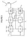
- Block 1represents a generic sensor device for obtaining data and for transmitting the acquired data.
- Block 2represents the data telecommunications networks (and their operating companies) over which the data is transmitted to the device 1 so as to trigger a response to data which is transmitted from the device 1 either in response to a change in the circumstances of the device, to a signal initiated by an internal clock or in response to a request received to and from a processing centre shown at 3.
- Block 4represents a user of the system for which the data, perhaps after analysis in block 3, is eventually returned. The directions of transmission of the data are shown by the headed arrows.
- FIG. 2shows a conventional representation of the public services telephone network at 5.
- the PSTN 5Connected to the PSTN 5 are a number of blocks 1a...1n each corresponding to block 1 of Figure 1 .
- these devicesneed not be identical and may in fact have a number of different functions. It is for this reason that some of the devices are connected to the PSTN 5 by double headed arrows indicating that they are capable of both receiving and transmitting data to the centre 3 whilst other devices only have a single headed arrow indicating that they are only capable of sending data to the centre 3.
- FIG. 3is a block diagram of circuitry which can be employed in the devices 1a...1n.
- the block diagramcomprises a sensor 6 shown in the figure as having two data inputs, data 1 and data 2 and adapted to send data corresponding to the two inputs to a second generation transmit/receive circuit 7.
- the circuit 7operates under the control of a microprocessor CPU unit 8 which also controls a clock 9.
- the clockreduces power consumption of the sensor by only switching the sensor on in response to appropriate commands from the CPU 8.
- the devicehas a power saving sleep mode.
- the sensorcan sense data 1 and data 2 either simultaneously or at staggered intervals which need not be the same.
- the transmit/receive circuit 7, the CPU 8, and the clock 9may all be formed as a microcircuit on a single chip.
- the circuitcan include an optional memory 10 and also includes a power source 11 which can be any suitable small battery such as the lithium batteries used to power calculators and digital watches. It is of course entirely possible for the power source to include photocells so that electrical energy can be generated by ambient light.
- the nature of the sensorhas not been specified and it is of course possible for the sensor to have only a single data input or a plurality of data inputs greater than two in number in accordance with the functions of the sensor within the overall system.
- the device shown in Figure 3is essentially a generic one and that certain of the devices shown in Figure 2 have only a one-way communication path with the PSTN 5 so that they cannot be interrogated by the centre 3.
- the send/receive circuit 7need of course only have a send capability so that it can be simplified.
- efficiencies of scaleit may be simpler to have a send/receive capability in every device with the receive facility only being enabled in the appropriate circumstances.
- device 1ais concerned with monitoring a drug testing program in which the patient has to take a regular dosage of the drug under test and in which a drug company is interested in the patient's response to this dosage.
- the drug companyit is accordingly necessary for the drug company to know both when a pill is taken and the response by the patient to the taking of the drug.
- the device 1awill merely indicate that the patient has opened the pill receptacle.
- the senorOn the opening of the receptacle, the sensor is intended to give an instruction to the transmit circuit to send a short text message to the processing centre 3 where the fact that the receptacle has been opened, and the timing of its opening, is logged for future analysis and transmission to the initial user, namely the drug company, for whom the data is intended.
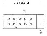
- Figure 4 of the drawingsshows a typical receptacle for pills in the form of a laminated strip 20 having an electro conductive metal foil surface provided with recesses 21 each holding a single pill.
- the sensor and its associated circuitry and power supplyare located at 22.
- the sensorwhich causes the send circuit 7, shown in Figure 5 , to send the appropriate message.
- the laminated foilis again shown at 20 and provides a conductive path between the power source 11 and the sensor 6 which path is changed each time the laminate is broken to enable the patient to remove a pill. Accordingly the sensor 6 can operate by detecting changes in the resistance or capacitance of the conductive foil.
- the foil and the various items of circuitryare mounted on a backing strip 22 of suitable material such as thick paper or cardboard which is relatively tougher than that of the foil so that a user will preferentially break the laminate to activate the sensor.
- suitable materialsuch as thick paper or cardboard which is relatively tougher than that of the foil so that a user will preferentially break the laminate to activate the sensor.
- datawill be transmitted to the centre 3 on the transmission of a polling request from the centre 3.
- the breaking of the foilmight not cause the immediate transmission of a signal to the centre 3 but will merely cause the fact that the foil has been broken to be stored in memory. Accordingly, when a request is received the stored data will then be sent as before.
- information about the timing of each pill's removalcan be stored in memory contained within the foil pack, and all such stored data may be transmitted in a single communications session, so that the battery power requirements of the foil pack, and thus its size and weight, are reduced.
- the sensor 6will accept a number of different inputs so that the required information can eventually be transmitted to the main centre 3. Additionally in order to conserve power the sensor may only be activated in response to a request received at the circuit 7 for stored information to be sent as text messages back to the centre 3.
- One way of ensuring that the data is relevantwould be to time the polling request appropriately in response to data already transmitted with regard to the timing of the patient's taking of the drug. In this scenario it is assumed that there is no direct linkage between the sensor monitoring the patient's condition and the sensor monitoring the taking of the drugs.
- one or other of the devicescould send its stored data to be appended to the data stored in the other device so that on interrogation from the centre 3 all the appropriate data is transmitted at the same time.
- the device associated directly with the patientcould be in the form of a bracelet worn by the patient or in the form of a patch such as one or more electrodes attached directly to the patient's skin by suitable adhesives or taping and worn under the patient's clothing.
- step S4a computer (not shown) at centre generates a log indicating that a particular patient has taken a particular pill at a particular time.
- step S4the centre 3 sends a request to interrogate the sensor 6b and to request the latter to transmit in step S5 the data that it has acquired back to the centre 3 so that this data can be added to the log generated at step S3.
- the data accessed in the transmit request step S4can also include previous data which has been stored by the sensor 6b at appropriate intervals after the last time it was polled by the centre 3.
- step S8the centre 3 generates a poll signal to interrogate the stored data.
- step S9makes the decision as to whether or not one or more pills have been taken since the last poll of the device. This information would of course be of importance to the company making the drug trial. Whether or not a pill has been taken data concerning the patients condition is transmitted in step S10 and the fact that a pill has been taken is flagged in step S11. If a pill has not been taken this information is also supplied to step S12 where a log of the available data is generated for subsequent use.
- Figure 8shows the receptacle in the form of a standard pill bottle 30.
- the sensor 6will merely record for transmission the removal of the led of the bottle.
- Figure 9shows a bracelet 40 which can be worn by a user, in order to detect variations in the user's bodily functions.
- the basic sensor configuration shown in Figure 3has the potential to carry out a wide range of functions.
- the device shown at 1b in Figure 2could be utilised to detect the possibility of impending heart attacks in a patient.
- the sensor 6has appropriate sensors and embedded software that detect heart beat patterns that are known to be precursors of a heart attack. When these are detected by the CPU the transmit section will be enabled to send an appropriate message to the centre 3 so that emergency services could be alerted. It is of course possible also to alert the wearer with the risk that the shock might advance the heart attack.
- the senor just describedcould be associated with machinery rather than with individual humans so as to detect actual or imminent failure and alert owners or maintenance companies.
- the sensorscan also provide useful data to manufacturers about the conditions under which a product fails.
- Sensor 1c in Figure 2is shown as having a GPS capability and in this variant of the invention the sensor 6 is a motion location sensor and the send/receive circuit 7 can be simplified so that it is a single-use message sender.
- Such a devicecan be attached to valuable items so that if they are moved the police will be alerted. Combining this feature with the GPS capability the device will also be able to tell the police where the article is.
- one of the advantages of the centre 3is that it can operate on behalf of a number of clients and that it will also generate a substantial amount of secondary data.
- each sensormay have a sleep mode in which there is minimal power consumption in such a case the sensor might only respond to a polling signal from the centre 3 and be quiescent until the polling signal has been received.
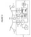
- FIG 10again shows the PSTN network at 5 and sensor devices 1a...1n. As before some of these devices have only a transmit capability and others have a receive/transmit capability.
- blocks 41a, 41b and 41crepresent receive terminals for receiving data signals from devices similar to send only device 1a or for both sending data to and receiving data from sensor devices such as device In.
- terminal 41arepresents a receive-only terminal
- terminals 41b and 41care transmit/receive terminals.
- Each terminalis capable of at least receiving data from a large number of sensor devices, and some terminals can also transmit to a large number of sensor devices.
- Associated with each terminalis an electronic processor.
- Terminal 41ais shown connected to a processor 42 whilst terminals 41b, 41c are shown connected to a data processing system 44.
- Processor 42on receipt of data from a sensor devise is programmed to recognise the source of the data and to log the data, including time of receipt, in an appropriate storage area 43.
- Data processing system 44is also capable of generating outgoing data such as polling calls and is also programmed to store in appropriate files details of all outgoing and incoming data as required by a user of the system. As already discussed power conservation is an important factor in the operation of the various sensors.
- polling terminal 40also includes a system clock which can be of any suitable type. Each processor can have its own clock or, as shown a single clock can be used.
- Data processing system 44also includes a storage area 46 storing Sensor Timing Data, namely the time at which each sensor which is to be polled in synchronism with that sensor's clock switching the sensor on and in addition, if there are passive sensors, the times at which data is expected to be received from the sensors.
- the data processing system 44also includes a stored set of batch routines indicated at 47 in order to control the polling of target sensors at appropriate times as set by the STD file 46.
- the batching routinecan also flag if a non-polled sensor has been quiescent for too long a period in response to data stored on the same file area.
- each sensor clock 9is in nominal synchronism with the system clock or its associated clock then the combination of the synchronised clocks, the STD file and the Batch routine will ensure that each device to be polled can remain in a very lower power. Mode with only its clock operational and its memory contents refreshed except when data is required. Naturally the polling times will vary with polling intervals for security sensors being shorter than those, for example, drug testing.
Landscapes
- Engineering & Computer Science (AREA)
- Health & Medical Sciences (AREA)
- Biomedical Technology (AREA)
- General Health & Medical Sciences (AREA)
- Medical Informatics (AREA)
- Computer Networks & Wireless Communication (AREA)
- Life Sciences & Earth Sciences (AREA)
- Signal Processing (AREA)
- Public Health (AREA)
- Physics & Mathematics (AREA)
- Heart & Thoracic Surgery (AREA)
- Computing Systems (AREA)
- General Physics & Mathematics (AREA)
- Biophysics (AREA)
- Veterinary Medicine (AREA)
- Surgery (AREA)
- Animal Behavior & Ethology (AREA)
- Pathology (AREA)
- Molecular Biology (AREA)
- Business, Economics & Management (AREA)
- General Business, Economics & Management (AREA)
- Epidemiology (AREA)
- Primary Health Care (AREA)
- Mobile Radio Communication Systems (AREA)
- Arrangements For Transmission Of Measured Signals (AREA)
- Alarm Systems (AREA)
Abstract
Description
- The present invention concerns a data acquisition and transfer system for transferring data via the mobile phone network. It is particularly but not exclusively concerned with the transfer of data from individuals to a central reception point and it is contemplated that the data may take many different forms. However, one important feature with which the present invention is concerned is that the major telecommunications operators and electronic suppliers are at present involved in the complex and difficult process of moving from the second generation of mobile phones to the third generation. As a result of this shift major companies are going to own increasingly under-utilised second generation digital networks and manufacturing capabilities for some time to come. Thus an aspect of the present invention is concerned with providing a range of opportunities which will enable these under-utilised facilities to remain revenue generating in a profitable manner.
- One such opportunity lies in the field of drug testing. The process of testing new drugs in order to have them approved by the appropriate regulatory bodies can cost major drug firms up to a million dollars in lost revenue for each extra day needed to get approval.
- One of the reasons it takes so long to get drugs approved is the length of time it takes to get sufficient good quality data out of the trials which have to be carried out. Doctors frequently mis-record data, and double-blind trials are expensive and take time to arrange. It is believed that schemes already exist to bypass the problems raised for example by doctors' handwriting and other vagaries in which test data is captured via the web. However errors still occur and the data is often inaccurate.
- Thus in accordance with one aspect of the present invention data will be collected directly from the patient and from the receptacle from which the trail drug is dispensed.
- It will, however, be appreciated that the basic inventive concept is applicable to a wide range of fields and is not necessarily limited to the concept of drug trials. Thus as will be apparent from the following description the inventive concept is applicable to monitoring the health of individuals who are not undergoing drug trials, locating or monitoring individuals for security purposes and also for carrying out regular checks on operating machinery.
EP 0 784 387 A2 refers to a means of optimising throughput on a communications channel shared by multiple users. The system combines a carrier sense, multiple access (CSMA) mode with a time division multiple access (TDMA) mode to achieve a channel utilisation greater than 90 %. The remote units send a poll request to a base station using the CSMA mode and receive a poll signal from the base station with a poll sequence. The remote units send their data in their assigned time slot.US 5 905 247 A refers to a parking fee system including a parking fee register in which information is maintained on one or more vehicles known to the system for which payment is made for parking, a vehicle-specific identification device from which a vehicle code of a vehicle is machine readable, and a control device for automatically reading the vehicle code from the vehicle-specific identification device for transmitting a control request message containing the vehicle code to the parking fee register, and for receiving a control information message reporting on the payment or non-payment of the parking fee and for notifying a user of the device of the information included in the control information message.US 4 685 149 A refers to a meteor burst communication system including at least two spaced apart master stations, in association with a plurality of groups of remote stations spaced at locations remote from the master stations, with each group being associated with one of the master stations. Each of the master stations includes a radio transmitter for transmitting probing digital radio signals having address portions which are directed from the master station for reflection from meteor trails to the remote stations associated with the master station. Each of the remote stations includes a radio receiver for receiving the reflected probing digital radio signals from the master stations. Each of the remote stations also includes at least one sensor of physical characteristics such as snow depth or rain fall. The remote stations each include a transmitter for transmitting digital data representative of the output of the associated sensor to the master station via reflection from a meteor vapour trail, if the received address portion compares with the stored digital address sequence in accordance with predetermined criteria.- A data receiver station and a system according to the invention are disclosed in
claims Figure 1 is a schematic diagram of the overall system architecture;Figure 2 is a diagram showing elements of the present invention in conjunction with the public services telephone network;Figure 3 is a block diagram of a sensor/transmitter;Figure 4 is a plan view of a pill receptacle which can be used in the system shown inFigures 1 and2 ;Figure 5 is a block diagram of the active components ofFigure 4 ;Figures 6 and7 are flow charts showing modes of operation of the device ofFigure 5 ;Figure 8 shows another form of pill receptacle;Figure 9 shows a sensor bracelet; andFigure 10 is a block diagram of data reception and polling terminal incorporating the present invention.- Referring now to the drawings,
Figure 1 represents in a generic fashion a family of monitoring and transmitting devices which will be described in greater detail hereinafter.Block 1 represents a generic sensor device for obtaining data and for transmitting the acquired data.Block 2 represents the data telecommunications networks (and their operating companies) over which the data is transmitted to thedevice 1 so as to trigger a response to data which is transmitted from thedevice 1 either in response to a change in the circumstances of the device, to a signal initiated by an internal clock or in response to a request received to and from a processing centre shown at 3. Block 4 represents a user of the system for which the data, perhaps after analysis inblock 3, is eventually returned. The directions of transmission of the data are shown by the headed arrows. - Turning now to
Figure 2 of the accompanying drawings, this shows a conventional representation of the public services telephone network at 5. Connected to thePSTN 5 are a number ofblocks 1a...1n each corresponding toblock 1 ofFigure 1 . As will be appreciated these devices need not be identical and may in fact have a number of different functions. It is for this reason that some of the devices are connected to thePSTN 5 by double headed arrows indicating that they are capable of both receiving and transmitting data to thecentre 3 whilst other devices only have a single headed arrow indicating that they are only capable of sending data to thecentre 3. As there are several different types ofdevice 1, there may also be several different organisations each interested in acquiring data so thatFigure 2 shows threesuch organisations 4a...4c. - Turning now to
Figure 3 of the accompanying drawings, this is a block diagram of circuitry which can be employed in thedevices 1a...1n. Thus the block diagram comprises asensor 6 shown in the figure as having two data inputs,data 1 anddata 2 and adapted to send data corresponding to the two inputs to a second generation transmit/receivecircuit 7. Thecircuit 7 operates under the control of amicroprocessor CPU unit 8 which also controls aclock 9. The clock reduces power consumption of the sensor by only switching the sensor on in response to appropriate commands from theCPU 8. Thus in several of its potential functions the device has a power saving sleep mode. Thus the sensor can sensedata 1 anddata 2 either simultaneously or at staggered intervals which need not be the same. Because of the possibility that the sensors may be required to operate over extended periods of time the question of power usage is of considerable importance and this feature will be described in greater detail hereinafter in conjunction withFigure 10 of the accompanying drawings. The transmit/receivecircuit 7, theCPU 8, and theclock 9 may all be formed as a microcircuit on a single chip. The circuit can include anoptional memory 10 and also includes apower source 11 which can be any suitable small battery such as the lithium batteries used to power calculators and digital watches. It is of course entirely possible for the power source to include photocells so that electrical energy can be generated by ambient light. - It will be appreciated that the nature of the sensor has not been specified and it is of course possible for the sensor to have only a single data input or a plurality of data inputs greater than two in number in accordance with the functions of the sensor within the overall system.
- It will be appreciated that the device shown in
Figure 3 is essentially a generic one and that certain of the devices shown inFigure 2 have only a one-way communication path with thePSTN 5 so that they cannot be interrogated by thecentre 3. In these devices the send/receivecircuit 7 need of course only have a send capability so that it can be simplified. Naturally if efficiencies of scale are present it may be simpler to have a send/receive capability in every device with the receive facility only being enabled in the appropriate circumstances. - One embodiment of a device such as 1a will now be described with regard to
Figures 4 and5 of the accompanying drawings. Thusdevice 1a is concerned with monitoring a drug testing program in which the patient has to take a regular dosage of the drug under test and in which a drug company is interested in the patient's response to this dosage. In this embodiment it is accordingly necessary for the drug company to know both when a pill is taken and the response by the patient to the taking of the drug. In its simplest form thedevice 1a will merely indicate that the patient has opened the pill receptacle. On the opening of the receptacle, the sensor is intended to give an instruction to the transmit circuit to send a short text message to theprocessing centre 3 where the fact that the receptacle has been opened, and the timing of its opening, is logged for future analysis and transmission to the initial user, namely the drug company, for whom the data is intended. Figure 4 of the drawings shows a typical receptacle for pills in the form of alaminated strip 20 having an electro conductive metal foil surface provided withrecesses 21 each holding a single pill. The sensor and its associated circuitry and power supply are located at 22. When the patient breaks the laminated foil to remove a pill, this is detected by the sensor which causes thesend circuit 7, shown inFigure 5 , to send the appropriate message. InFigure 5 the laminated foil is again shown at 20 and provides a conductive path between thepower source 11 and thesensor 6 which path is changed each time the laminate is broken to enable the patient to remove a pill. Accordingly thesensor 6 can operate by detecting changes in the resistance or capacitance of the conductive foil. The foil and the various items of circuitry are mounted on abacking strip 22 of suitable material such as thick paper or cardboard which is relatively tougher than that of the foil so that a user will preferentially break the laminate to activate the sensor. Given that the device employs a microprocessor and associated memory it is possible to pre-program the device with a schedule so that if the schedule is not followed an alert message is transmitted to thecentre 3.- In applications where the intervals between pills being taken are not critical to the safety of the patient, a more sophisticated embodiment of the present invention may be used. In one such embodiment, data will be transmitted to the
centre 3 on the transmission of a polling request from thecentre 3. In such a case the breaking of the foil might not cause the immediate transmission of a signal to thecentre 3 but will merely cause the fact that the foil has been broken to be stored in memory. Accordingly, when a request is received the stored data will then be sent as before. In another variant information about the timing of each pill's removal can be stored in memory contained within the foil pack, and all such stored data may be transmitted in a single communications session, so that the battery power requirements of the foil pack, and thus its size and weight, are reduced. - There will now be described a more sophisticated variant of the device just described with reference to
Figures 4 and5 . As already mentioned it may well be that the drug company instigating the tests will require further information in addition to the fact that a patient has been taking his/her pills at the appropriate times and logging the times at which the pills were taken. Thus it is entirely possible for the drug company to wish to be able to monitor changes in the patient's condition when undergoing the drug regime. In such a situation it may be necessary for the patient to be provided with two sensing and transmitting devices. One device could be similar to the device just described with regard toFigures 4 and5 whilst the other device could be a more sophisticated variant of this device which is attached to the patient and which monitors factors relevant to the patient's state of health. Such factors could be blood pressure, temperature, heart rate, skin pH and perspiration rate etc. and will of course depend on the nature of the drug being tested. Accordingly in this variant of the present invention thesensor 6 will accept a number of different inputs so that the required information can eventually be transmitted to themain centre 3. Additionally in order to conserve power the sensor may only be activated in response to a request received at thecircuit 7 for stored information to be sent as text messages back to thecentre 3. One way of ensuring that the data is relevant would be to time the polling request appropriately in response to data already transmitted with regard to the timing of the patient's taking of the drug. In this scenario it is assumed that there is no direct linkage between the sensor monitoring the patient's condition and the sensor monitoring the taking of the drugs. However, in another variant one or other of the devices could send its stored data to be appended to the data stored in the other device so that on interrogation from thecentre 3 all the appropriate data is transmitted at the same time. - The device associated directly with the patient could be in the form of a bracelet worn by the patient or in the form of a patch such as one or more electrodes attached directly to the patient's skin by suitable adhesives or taping and worn under the patient's clothing.
- The flow diagrams of
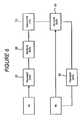
Figures 6 and7 show alternative ways in which the generated data can be accessed by thecentre 3. In these flow diagrams 6a represents thesensor 6 shown inFigures 4 and5 and 6b represents a similar sensor but monitoring health characteristics of the patient involved. It will be appreciated that both of these sensors are similar to the one described with reference toFigure 3 . - In the flow diagram of
Figure 6 it is assumed that thesensor 6a operates in its normal manner and when a pill is taken transmits this fact at step S1 to thecentre 3 where it is received at step S2. At step S3 a computer (not shown) at centre generates a log indicating that a particular patient has taken a particular pill at a particular time. In step S4 thecentre 3 sends a request to interrogate thesensor 6b and to request the latter to transmit in step S5 the data that it has acquired back to thecentre 3 so that this data can be added to the log generated at step S3. Naturally the data accessed in the transmit request step S4 can also include previous data which has been stored by thesensor 6b at appropriate intervals after the last time it was polled by thecentre 3. - In the flow diagram of
Figure 7 an alternative scenario is shown in which the output ofsensor 6a in response to the removal of a pill is stored in memory at step S8 together with data fromsensor 6b for subsequent transmission. In step S8 thecentre 3 generates a poll signal to interrogate the stored data. - In response to this interrogation step a step S9 makes the decision as to whether or not one or more pills have been taken since the last poll of the device. This information would of course be of importance to the company making the drug trial. Whether or not a pill has been taken data concerning the patients condition is transmitted in step S10 and the fact that a pill has been taken is flagged in step S11. If a pill has not been taken this information is also supplied to step S12 where a log of the available data is generated for subsequent use.
- It will be appreciated that the embodiment of
Figure 7 could be changed in a relatively simple manner by keeping the data separate in two streams in which eachmemory 10 of each sensor device is interrogated by thecentre 1 with each sensor device sending its relevant data independently of the other to generate the final log at thecentre 1. - It will be appreciated that in the system just described the quality of data gathered is likely to be much more accurate than similar data gathered by a doctor or even from a patients own records and it would also be gathered much faster. The advantage for this for the drug company carrying out the tests is clear in that there will be reduced time delay before a successful drug can be marketed. Additionally for the telecommunication network operator the advantage is higher utilisation of their network, but with limited life span contract thus for a drug testing program each sensor might be required to be able to operate over a matter of a few weeks or months. For the electronic suppliers there will be the corresponding advantage of the opportunity to get more utilisation out of their 2g second generation cellular telephone chip set production capabilities. However, it must be appreciated that exactly the same concept may be applied when inevitable progress means a move from third generation chip sets to fourth generation chip sets and so on.
- It must be appreciated that the receptacle for pills disclosed in
Figures 4 and5 can take other forms. ThusFigure 8 shows the receptacle in the form of astandard pill bottle 30. In such a case thesensor 6 will merely record for transmission the removal of the led of the bottle. Figure 9 shows abracelet 40 which can be worn by a user, in order to detect variations in the user's bodily functions.- As already mentioned the basic sensor configuration shown in
Figure 3 has the potential to carry out a wide range of functions. Thus the device shown at 1b inFigure 2 could be utilised to detect the possibility of impending heart attacks in a patient. In this case, thesensor 6 has appropriate sensors and embedded software that detect heart beat patterns that are known to be precursors of a heart attack. When these are detected by the CPU the transmit section will be enabled to send an appropriate message to thecentre 3 so that emergency services could be alerted. It is of course possible also to alert the wearer with the risk that the shock might advance the heart attack. - In an exactly equivalent manner the sensor just described could be associated with machinery rather than with individual humans so as to detect actual or imminent failure and alert owners or maintenance companies. The sensors can also provide useful data to manufacturers about the conditions under which a product fails.
- Sensor 1c in
Figure 2 is shown as having a GPS capability and in this variant of the invention thesensor 6 is a motion location sensor and the send/receivecircuit 7 can be simplified so that it is a single-use message sender. Such a device can be attached to valuable items so that if they are moved the police will be alerted. Combining this feature with the GPS capability the device will also be able to tell the police where the article is. - As is apparent from the foregoing description one of the advantages of the
centre 3 is that it can operate on behalf of a number of clients and that it will also generate a substantial amount of secondary data. - In all of the variants described above the question of maintaining a sufficient power supply for the sensors and their associated send/receive circuits is of considerable importance. In order to conserve power each sensor may have a sleep mode in which there is minimal power consumption in such a case the sensor might only respond to a polling signal from the
centre 3 and be quiescent until the polling signal has been received. - Turning now to
Figure 10 of the accompanying drawings this shows in greater detail a data reception andpolling terminal 40 corresponding to thecentre 3 shown inFigure 2 . Figure 10 again shows the PSTN network at 5 andsensor devices 1a...1n. As before some of these devices have only a transmit capability and others have a receive/transmit capability.- In the centre of
polling terminal 40blocks only device 1a or for both sending data to and receiving data from sensor devices such as device In. Thus terminal 41a represents a receive-only terminal, whilstterminals 41b and 41c are transmit/receive terminals. Each terminal is capable of at least receiving data from a large number of sensor devices, and some terminals can also transmit to a large number of sensor devices. Associated with each terminal is an electronic processor. Terminal 41a is shown connected to aprocessor 42 whilstterminals 41b, 41c are shown connected to adata processing system 44.Processor 42 on receipt of data from a sensor devise is programmed to recognise the source of the data and to log the data, including time of receipt, in anappropriate storage area 43. Data processing system 44 is also capable of generating outgoing data such as polling calls and is also programmed to store in appropriate files details of all outgoing and incoming data as required by a user of the system. As already discussed power conservation is an important factor in the operation of the various sensors. Thus it will be seen thatpolling terminal 40 also includes a system clock which can be of any suitable type. Each processor can have its own clock or, as shown a single clock can be used.Data processing system 44 also includes astorage area 46 storing Sensor Timing Data, namely the time at which each sensor which is to be polled in synchronism with that sensor's clock switching the sensor on and in addition, if there are passive sensors, the times at which data is expected to be received from the sensors. Thedata processing system 44 also includes a stored set of batch routines indicated at 47 in order to control the polling of target sensors at appropriate times as set by theSTD file 46. The batching routine can also flag if a non-polled sensor has been quiescent for too long a period in response to data stored on the same file area. Provided that eachsensor clock 9 is in nominal synchronism with the system clock or its associated clock then the combination of the synchronised clocks, the STD file and the Batch routine will ensure that each device to be polled can remain in a very lower power. Mode with only its clock operational and its memory contents refreshed except when data is required. Naturally the polling times will vary with polling intervals for security sensors being shorter than those, for example, drug testing.
Claims (10)
- A data receiver station (40), comprising:a first transmitter (41 b, 41 c) configured to transmit a first polling signal at a first time and a second polling signal at a second polling time,wherein the first transmitter (41 b, 41 c) is configured to transmit the first polling signal over a data telecommunications network (5) to a data acquisition and transfer device (1, 1 c, 1 n) requesting a first data associated with a change detected by a first sensor (1 a, 1b, 1 d, 6a), andwherein the first transmitter (41 b, 41 c) is configured to transmit the second polling signal to the data acquisition and transfer device (1, 1c, 1 n) requesting a second data associated with a change detected by a second sensor;a first receiver (41b, 41c) configured to receive the first and second data sent in response to and after the first polling signal,wherein the first receiver (41b, 41c) is configured to receive the first and second data over the data telecommunications network (5); anda controller (44) coupled to the first transmitter (41b, 41c) and the first receiver (41b, 41c) and configured to determine the second polling time depending upon a content of the first data including an indication of when the first sensor (1a, 1b, 1d, 6a) detected the change received by the first receiver (41b, 41c) and to control the first transmitter (41b, 41c) to send the second polling signal at the second time,wherein the controller (44) is configured to determine the time for sending the second polling signal depending upon when the first sensor (1a, 1b, 1d, 6a) detected the change.
- The data receiver station of claim 1, wherein the content of the data includes an indication of when a sensor detected a change in a physical characteristic.
- The data receiver station of and one of claims 1 to2, further including a memory, wherein the controller is further configured to determine a time of receipt of the data and to store both the content of the data and the time of receipt of the data in the memory.
- The data receiver station of any one of claims 1 to 3, the data acquisition and transfer device having first and second sensors each responsive to a change of a predetermined nature and a transmitter for transmitting over a mobile phone network data concerning an occurrence of each change to the data receiver station, wherein the data receiver station comprises:the controller is configured to determine a time for sending the second polling signal depending upon a content of the first data and to control the transmitter to send the second polling signal at the determined time.
- The data receiver station of claim 4, wherein the content of the first data includes an indication of when the first sensor detected the change, and wherein the controller is configured to determine the time for sending the second polling signal depending upon when the first sensor detected the change.
- A data acquisition system, comprising:the data receiver station (3, 40) of any one of claims 1 to 4, and:a data acquisition device (1, 1 c, 1n), comprising:a second receiver (7) configured to receive over the data telecommunications network (2, 5) the first and second polling signals,a first sensor (6a) configured to sense a first physical characteristic,a second sensor (6b) configured to sense a second physical characteristic, anda second transmitter (7) configured to transmit the first and second data,wherein the data acquisition device (1, 1 c, 1n) is configured to generate the first data based on the first physical characteristic as sensed by the first sensor (6a) and to generate the second data based on the second physical characteristic as sensed by the second sensor (6b),wherein the content of the first data includes an indication of when the first sensor detected the first physical characteristic, andwherein the data acquisition device (1, 1c, 1n) is further configured to transmit by the second transmitter (7) the first data in response to the second receiver (7) receiving the first polling signal and the second data in response to the second receiver (7) receiving the second polling signal.
- The data acquisition system of claim 6, wherein the controller is configured to determine the time for sending the second polling signal depending upon when the first sensor detected the first physical characteristic.
- The data acquisition system of claim 6 or claim 7, wherein the network is a phone network.
- The data acquisition device of any one of claims 6 to 8, further including a memory, wherein the controller is further configured to determine a time of receipt of the first data and to store both the content of the first data and the time of receipt of the first data in the memory.
- The data acquisition device of any one of claims 6 to 9, wherein the first and second physical characteristics are changes in physical characteristics.
Priority Applications (1)
| Application Number | Priority Date | Filing Date | Title |
|---|---|---|---|
| EP10011942.9AEP2374406B1 (en) | 2003-01-30 | 2003-01-30 | Event data acquisition and transmission system |
Applications Claiming Priority (2)
| Application Number | Priority Date | Filing Date | Title |
|---|---|---|---|
| EP10011942.9AEP2374406B1 (en) | 2003-01-30 | 2003-01-30 | Event data acquisition and transmission system |
| EP03250577.8AEP1443780B1 (en) | 2003-01-30 | 2003-01-30 | Event data acquisition and transmission system |
Related Parent Applications (1)
| Application Number | Title | Priority Date | Filing Date |
|---|---|---|---|
| EP03250577.8Division | 2003-01-30 |
Publications (2)
| Publication Number | Publication Date |
|---|---|
| EP2374406A1 EP2374406A1 (en) | 2011-10-12 |
| EP2374406B1true EP2374406B1 (en) | 2013-06-05 |
Family
ID=32605397
Family Applications (2)
| Application Number | Title | Priority Date | Filing Date |
|---|---|---|---|
| EP10011942.9AExpired - LifetimeEP2374406B1 (en) | 2003-01-30 | 2003-01-30 | Event data acquisition and transmission system |
| EP03250577.8AExpired - LifetimeEP1443780B1 (en) | 2003-01-30 | 2003-01-30 | Event data acquisition and transmission system |
Family Applications After (1)
| Application Number | Title | Priority Date | Filing Date |
|---|---|---|---|
| EP03250577.8AExpired - LifetimeEP1443780B1 (en) | 2003-01-30 | 2003-01-30 | Event data acquisition and transmission system |
Country Status (4)
| Country | Link |
|---|---|
| US (1) | US7242318B2 (en) |
| EP (2) | EP2374406B1 (en) |
| CA (1) | CA2514799C (en) |
| WO (1) | WO2004068881A1 (en) |
Families Citing this family (77)
| Publication number | Priority date | Publication date | Assignee | Title |
|---|---|---|---|---|
| US20070103678A1 (en)* | 2005-02-14 | 2007-05-10 | Sterling Bernhard B | Analyte detection system with interferent identification and correction |
| US8730031B2 (en) | 2005-04-28 | 2014-05-20 | Proteus Digital Health, Inc. | Communication system using an implantable device |
| US8912908B2 (en) | 2005-04-28 | 2014-12-16 | Proteus Digital Health, Inc. | Communication system with remote activation |
| US8836513B2 (en) | 2006-04-28 | 2014-09-16 | Proteus Digital Health, Inc. | Communication system incorporated in an ingestible product |
| US8802183B2 (en) | 2005-04-28 | 2014-08-12 | Proteus Digital Health, Inc. | Communication system with enhanced partial power source and method of manufacturing same |
| US9198608B2 (en) | 2005-04-28 | 2015-12-01 | Proteus Digital Health, Inc. | Communication system incorporated in a container |
| EP3827747A1 (en) | 2005-04-28 | 2021-06-02 | Otsuka Pharmaceutical Co., Ltd. | Pharma-informatics system |
| US8547248B2 (en) | 2005-09-01 | 2013-10-01 | Proteus Digital Health, Inc. | Implantable zero-wire communications system |
| JP2009544338A (en) | 2006-05-02 | 2009-12-17 | プロテウス バイオメディカル インコーポレイテッド | Treatment regimen customized to the patient |
| EP2087589B1 (en) | 2006-10-17 | 2011-11-23 | Proteus Biomedical, Inc. | Low voltage oscillator for medical devices |
| SG175681A1 (en) | 2006-10-25 | 2011-11-28 | Proteus Biomedical Inc | Controlled activation ingestible identifier |
| US8718193B2 (en) | 2006-11-20 | 2014-05-06 | Proteus Digital Health, Inc. | Active signal processing personal health signal receivers |
| US8287281B2 (en)* | 2006-12-06 | 2012-10-16 | Microsoft Corporation | Memory training via visual journal |
| US7983933B2 (en)* | 2006-12-06 | 2011-07-19 | Microsoft Corporation | Patient monitoring via image capture |
| US8652040B2 (en) | 2006-12-19 | 2014-02-18 | Valencell, Inc. | Telemetric apparatus for health and environmental monitoring |
| BRPI0720856A2 (en)* | 2007-01-10 | 2014-03-25 | Camillo Ricordi | MOBILE EMERGENCY ALERT SYSTEM |
| US20080183049A1 (en)* | 2007-01-31 | 2008-07-31 | Microsoft Corporation | Remote management of captured image sequence |
| CN101686800A (en) | 2007-02-01 | 2010-03-31 | 普罗秋斯生物医学公司 | Ingestible Event Marker System |
| US8956288B2 (en) | 2007-02-14 | 2015-02-17 | Proteus Digital Health, Inc. | In-body power source having high surface area electrode |
| EP2063771A1 (en) | 2007-03-09 | 2009-06-03 | Proteus Biomedical, Inc. | In-body device having a deployable antenna |
| EP2124725A1 (en) | 2007-03-09 | 2009-12-02 | Proteus Biomedical, Inc. | In-body device having a multi-directional transmitter |
| US8115618B2 (en) | 2007-05-24 | 2012-02-14 | Proteus Biomedical, Inc. | RFID antenna for in-body device |
| DK2192946T3 (en) | 2007-09-25 | 2022-11-21 | Otsuka Pharma Co Ltd | In-body device with virtual dipole signal amplification |
| CN104376659B (en) | 2008-03-05 | 2019-10-25 | 普罗透斯数字保健公司 | The ingestible event flag of multi-modal communications and system, and the method using it |
| US20090243878A1 (en)* | 2008-03-31 | 2009-10-01 | Camillo Ricordi | Radio frequency transmitter and receiver system and apparatus |
| AU2009268827B2 (en) | 2008-07-08 | 2013-10-24 | Proteus Digital Health, Inc. | Ingestible event marker data framework |
| MY154217A (en) | 2008-08-13 | 2015-05-15 | Proteus Digital Health Inc | Ingestible circuitry |
| US8036748B2 (en) | 2008-11-13 | 2011-10-11 | Proteus Biomedical, Inc. | Ingestible therapy activator system and method |
| EP2358270A4 (en) | 2008-12-11 | 2014-08-13 | Proteus Digital Health Inc | Evaluation of gastrointestinal function using portable electroviscerography systems and methods of using the same |
| TWI503101B (en) | 2008-12-15 | 2015-10-11 | Proteus Digital Health Inc | Body-associated receiver and method |
| US9439566B2 (en) | 2008-12-15 | 2016-09-13 | Proteus Digital Health, Inc. | Re-wearable wireless device |
| US9659423B2 (en) | 2008-12-15 | 2017-05-23 | Proteus Digital Health, Inc. | Personal authentication apparatus system and method |
| SG172847A1 (en) | 2009-01-06 | 2011-08-29 | Proteus Biomedical Inc | Pharmaceutical dosages delivery system |
| KR20110103446A (en) | 2009-01-06 | 2011-09-20 | 프로테우스 바이오메디컬, 인코포레이티드 | Intake-Related Biofeedback and Individualized Medical Treatment Methods and Systems |
| WO2010111403A2 (en) | 2009-03-25 | 2010-09-30 | Proteus Biomedical, Inc. | Probablistic pharmacokinetic and pharmacodynamic modeling |
| CN101872537A (en)* | 2009-04-21 | 2010-10-27 | 深圳富泰宏精密工业有限公司 | Environment monitoring system and method |
| EP3906845A1 (en) | 2009-04-28 | 2021-11-10 | Otsuka Pharmaceutical Co., Ltd. | Highly reliable ingestible event markers |
| EP2432458A4 (en) | 2009-05-12 | 2014-02-12 | Proteus Digital Health Inc | Ingestible event markers comprising an ingestible component |
| US9167617B2 (en)* | 2009-06-26 | 2015-10-20 | Koninklijke Philips N.V. | Method for communicating in a mobile network implementing discontinuous reception |
| US8558563B2 (en) | 2009-08-21 | 2013-10-15 | Proteus Digital Health, Inc. | Apparatus and method for measuring biochemical parameters |
| TWI517050B (en) | 2009-11-04 | 2016-01-11 | 普羅托斯數位健康公司 | System for supply chain management |
| UA109424C2 (en) | 2009-12-02 | 2015-08-25 | PHARMACEUTICAL PRODUCT, PHARMACEUTICAL TABLE WITH ELECTRONIC MARKER AND METHOD OF MANUFACTURING PHARMACEUTICAL TABLETS | |
| BR112012019212A2 (en) | 2010-02-01 | 2017-06-13 | Proteus Digital Health Inc | data collection system |
| WO2011127252A2 (en) | 2010-04-07 | 2011-10-13 | Proteus Biomedical, Inc. | Miniature ingestible device |
| DK2568878T3 (en) | 2010-05-12 | 2018-10-29 | Irhythm Tech Inc | Interior features and design elements for long-term adhesion |
| TWI557672B (en) | 2010-05-19 | 2016-11-11 | 波提亞斯數位康健公司 | Computer system and computer-implemented method to track medication from manufacturer to a patient, apparatus and method for confirming delivery of medication to a patient, patient interface device |
| GB2484458A (en)* | 2010-10-04 | 2012-04-18 | Thorn Security | Commissioning detector units of an alarm system by means of a remote infrared based communication tool |
| JP2014504902A (en) | 2010-11-22 | 2014-02-27 | プロテウス デジタル ヘルス, インコーポレイテッド | Ingestible device with medicinal product |
| WO2012125425A2 (en) | 2011-03-11 | 2012-09-20 | Proteus Biomedical, Inc. | Wearable personal body associated device with various physical configurations |
| US9756874B2 (en) | 2011-07-11 | 2017-09-12 | Proteus Digital Health, Inc. | Masticable ingestible product and communication system therefor |
| WO2015112603A1 (en) | 2014-01-21 | 2015-07-30 | Proteus Digital Health, Inc. | Masticable ingestible product and communication system therefor |
| PH12014500174A1 (en) | 2011-07-21 | 2024-02-12 | Proteus Digital Health Inc | Mobile communication device, system, and method |
| US9235683B2 (en) | 2011-11-09 | 2016-01-12 | Proteus Digital Health, Inc. | Apparatus, system, and method for managing adherence to a regimen |
| EP2874886B1 (en) | 2012-07-23 | 2023-12-20 | Otsuka Pharmaceutical Co., Ltd. | Techniques for manufacturing ingestible event markers comprising an ingestible component |
| AU2013331417B2 (en) | 2012-10-18 | 2016-06-02 | Proteus Digital Health, Inc. | Apparatus, system, and method to adaptively optimize power dissipation and broadcast power in a power source for a communication device |
| KR102145450B1 (en) | 2013-01-24 | 2020-08-18 | 아이리듬 테크놀로지스, 아이엔씨 | Physiological monitoring device |
| US11149123B2 (en) | 2013-01-29 | 2021-10-19 | Otsuka Pharmaceutical Co., Ltd. | Highly-swellable polymeric films and compositions comprising the same |
| JP6498177B2 (en) | 2013-03-15 | 2019-04-10 | プロテウス デジタル ヘルス, インコーポレイテッド | Identity authentication system and method |
| WO2014144738A1 (en) | 2013-03-15 | 2014-09-18 | Proteus Digital Health, Inc. | Metal detector apparatus, system, and method |
| WO2014168841A1 (en) | 2013-04-08 | 2014-10-16 | Irhythm Technologies, Inc | Skin abrader |
| EP3005281A4 (en) | 2013-06-04 | 2017-06-28 | Proteus Digital Health, Inc. | System, apparatus and methods for data collection and assessing outcomes |
| US9796576B2 (en) | 2013-08-30 | 2017-10-24 | Proteus Digital Health, Inc. | Container with electronically controlled interlock |
| CA2965941C (en) | 2013-09-20 | 2020-01-28 | Proteus Digital Health, Inc. | Methods, devices and systems for receiving and decoding a signal in the presence of noise using slices and warping |
| WO2015044722A1 (en) | 2013-09-24 | 2015-04-02 | Proteus Digital Health, Inc. | Method and apparatus for use with received electromagnetic signal at a frequency not known exactly in advance |
| US10799173B2 (en) | 2013-10-18 | 2020-10-13 | Carepredict, Inc. | Fall prediction assessment |
| US10743811B2 (en) | 2013-10-18 | 2020-08-18 | Carepredict, Inc. | Fall prediction assessment |
| US10084880B2 (en) | 2013-11-04 | 2018-09-25 | Proteus Digital Health, Inc. | Social media networking based on physiologic information |
| US10104178B2 (en)* | 2014-05-27 | 2018-10-16 | Genesys Telecommunications Laboratories, Inc. | System for managing communications activated by a trigger event |
| WO2016070128A1 (en) | 2014-10-31 | 2016-05-06 | Irhythm Technologies, Inc. | Wireless physiological monitoring device and systems |
| US11051543B2 (en) | 2015-07-21 | 2021-07-06 | Otsuka Pharmaceutical Co. Ltd. | Alginate on adhesive bilayer laminate film |
| KR20210018961A (en) | 2016-07-22 | 2021-02-18 | 프로테우스 디지털 헬스, 인코포레이티드 | Electromagnetic sensing and detection of ingestible event markers |
| CN109963499B (en) | 2016-10-26 | 2022-02-25 | 大冢制药株式会社 | Method for manufacturing capsules with ingestible event markers |
| CN108597599B (en)* | 2018-04-28 | 2021-02-19 | 厦门理工学院 | A health monitoring system and method based on low-latency scheduling of cloud resources |
| EP4103051A1 (en) | 2020-02-12 | 2022-12-21 | Irhythm Technologies, Inc. | Non-invasive cardiac monitor and methods of using recorded cardiac data to infer a physiological characteristic of a patient |
| WO2022032118A1 (en) | 2020-08-06 | 2022-02-10 | Irhythm Technologies, Inc. | Electrical components for physiological monitoring device |
| US11350865B2 (en) | 2020-08-06 | 2022-06-07 | Irhythm Technologies, Inc. | Wearable device with bridge portion |
| USD1063079S1 (en) | 2021-08-06 | 2025-02-18 | Irhythm Technologies, Inc. | Physiological monitoring device |
Family Cites Families (18)
| Publication number | Priority date | Publication date | Assignee | Title |
|---|---|---|---|---|
| US4685149A (en)* | 1977-07-29 | 1987-08-04 | Rockwell International Corporation | Meteor scatter burst communication system |
| US4800538A (en)* | 1986-03-31 | 1989-01-24 | Refraction Technology, Inc. | Method of and systems for seismic exploration |
| US5297144A (en)* | 1991-01-22 | 1994-03-22 | Spectrix Corporation | Reservation-based polling protocol for a wireless data communications network |
| AU4626893A (en)* | 1992-09-14 | 1994-03-24 | Aprex Corporation | Contactless communication system |
| US5581707A (en)* | 1994-07-27 | 1996-12-03 | Psc, Inc. | System for wireless collection of data from a plurality of remote data collection units such as portable bar code readers |
| FI102018B (en)* | 1995-02-28 | 1998-09-30 | Payway Oy | Parking payment system, an inspection device and an identification device |
| US5737330A (en)* | 1996-01-11 | 1998-04-07 | Meteor Communications Corporation | System and method for the efficient control of a radio communications network |
| US5852590A (en)* | 1996-12-20 | 1998-12-22 | De La Huerga; Carlos | Interactive label for medication containers and dispensers |
| US6687190B2 (en)* | 1999-07-23 | 2004-02-03 | Robert Momich | Method and apparatus for clinical trials |
| US6294999B1 (en)* | 1999-12-29 | 2001-09-25 | Becton, Dickinson And Company | Systems and methods for monitoring patient compliance with medication regimens |
| US6471645B1 (en)* | 1999-12-30 | 2002-10-29 | Medtronic, Inc. | Communications system for an implantable device and a drug dispenser |
| AU2001232927A1 (en)* | 2000-01-24 | 2001-07-31 | Speakout.Com, Inc. | System, method and computer program product for collection of opinion data |
| US6441747B1 (en)* | 2000-04-18 | 2002-08-27 | Motorola, Inc. | Wireless system protocol for telemetry monitoring |
| US20030036683A1 (en)* | 2000-05-01 | 2003-02-20 | Kehr Bruce A. | Method, system and computer program product for internet-enabled, patient monitoring system |
| WO2002034331A2 (en)* | 2000-10-26 | 2002-05-02 | Medtronic, Inc. | Externally worn transceiver for use with an implantable medical device |
| EP1385570B1 (en)* | 2001-04-30 | 2006-09-13 | Medtronic, Inc. | Implantable medical device and patch system |
| US7044911B2 (en)* | 2001-06-29 | 2006-05-16 | Philometron, Inc. | Gateway platform for biological monitoring and delivery of therapeutic compounds |
| US6889165B2 (en)* | 2001-07-02 | 2005-05-03 | Battelle Memorial Institute | Application specific intelligent microsensors |
- 2003
- 2003-01-30EPEP10011942.9Apatent/EP2374406B1/ennot_activeExpired - Lifetime
- 2003-01-30EPEP03250577.8Apatent/EP1443780B1/ennot_activeExpired - Lifetime
- 2004
- 2004-01-29USUS10/769,206patent/US7242318B2/ennot_activeExpired - Lifetime
- 2004-01-30WOPCT/GB2004/000394patent/WO2004068881A1/enactiveApplication Filing
- 2004-01-30CACA2514799Apatent/CA2514799C/ennot_activeExpired - Fee Related
Also Published As
| Publication number | Publication date |
|---|---|
| EP1443780B1 (en) | 2013-05-29 |
| US20040183675A1 (en) | 2004-09-23 |
| EP1443780A1 (en) | 2004-08-04 |
| EP2374406A1 (en) | 2011-10-12 |
| US7242318B2 (en) | 2007-07-10 |
| WO2004068881A1 (en) | 2004-08-12 |
| CA2514799C (en) | 2013-09-24 |
| CA2514799A1 (en) | 2004-08-12 |
Similar Documents
| Publication | Publication Date | Title |
|---|---|---|
| EP2374406B1 (en) | Event data acquisition and transmission system | |
| US11232390B1 (en) | Item tracking system with electronic tracking labels containing sensors | |
| US10156466B2 (en) | Remote monitoring and transparency regarding liquid volume | |
| US9256910B2 (en) | Medical monitoring/consumables tracking device | |
| US20080054007A1 (en) | System and method for distributing medication and monitoring medication protocol compliance | |
| CA2401046A1 (en) | Apparatus and method for continuous electronic monitoring/tracking of individuals | |
| CN111630538A (en) | Tracking of products | |
| CN114092082A (en) | Consumption method and system of intelligent consumption machine based on multiple consumption situations | |
| CN101437617B (en) | assay device | |
| US20080270270A1 (en) | System and method for monitoring and management of inventory of products and assets in real time | |
| EP2585378B1 (en) | Fiber or plastic based packing, apparatus, method, program and system for wireless data communication by fiber or plastic based packing | |
| CN111201573A (en) | Portable medical data concentrator | |
| CN218528417U (en) | Medicine container with monitoring function | |
| US20100133103A1 (en) | Method and a device for monitoring physical conditions | |
| CN113673639A (en) | Medicine management service system for biological medicine | |
| TWM635654U (en) | Drug container and system with monitoring function |
Legal Events
| Date | Code | Title | Description |
|---|---|---|---|
| PUAI | Public reference made under article 153(3) epc to a published international application that has entered the european phase | Free format text:ORIGINAL CODE: 0009012 | |
| AC | Divisional application: reference to earlier application | Ref document number:1443780 Country of ref document:EP Kind code of ref document:P | |
| AK | Designated contracting states | Kind code of ref document:A1 Designated state(s):AT BE BG CH CY CZ DE DK EE ES FI FR GB GR HU IE IT LI LU MC NL PT SE SI SK TR | |
| 17P | Request for examination filed | Effective date:20120412 | |
| RAP1 | Party data changed (applicant data changed or rights of an application transferred) | Owner name:ACCENTURE GLOBAL SERVICES LIMITED | |
| RIC1 | Information provided on ipc code assigned before grant | Ipc:H04W 74/06 20090101ALI20120928BHEP Ipc:A61B 5/00 20060101AFI20120928BHEP | |
| GRAP | Despatch of communication of intention to grant a patent | Free format text:ORIGINAL CODE: EPIDOSNIGR1 | |
| GRAS | Grant fee paid | Free format text:ORIGINAL CODE: EPIDOSNIGR3 | |
| GRAA | (expected) grant | Free format text:ORIGINAL CODE: 0009210 | |
| AC | Divisional application: reference to earlier application | Ref document number:1443780 Country of ref document:EP Kind code of ref document:P | |
| AK | Designated contracting states | Kind code of ref document:B1 Designated state(s):AT BE BG CH CY CZ DE DK EE ES FI FR GB GR HU IE IT LI LU MC NL PT SE SI SK TR | |
| REG | Reference to a national code | Ref country code:GB Ref legal event code:FG4D | |
| REG | Reference to a national code | Ref country code:CH Ref legal event code:EP | |
| REG | Reference to a national code | Ref country code:AT Ref legal event code:REF Ref document number:615168 Country of ref document:AT Kind code of ref document:T Effective date:20130615 | |
| REG | Reference to a national code | Ref country code:IE Ref legal event code:FG4D | |
| REG | Reference to a national code | Ref country code:DE Ref legal event code:R096 Ref document number:60344243 Country of ref document:DE Effective date:20130801 | |
| REG | Reference to a national code | Ref country code:AT Ref legal event code:MK05 Ref document number:615168 Country of ref document:AT Kind code of ref document:T Effective date:20130605 | |
| PG25 | Lapsed in a contracting state [announced via postgrant information from national office to epo] | Ref country code:SI Free format text:LAPSE BECAUSE OF FAILURE TO SUBMIT A TRANSLATION OF THE DESCRIPTION OR TO PAY THE FEE WITHIN THE PRESCRIBED TIME-LIMIT Effective date:20130605 Ref country code:FI Free format text:LAPSE BECAUSE OF FAILURE TO SUBMIT A TRANSLATION OF THE DESCRIPTION OR TO PAY THE FEE WITHIN THE PRESCRIBED TIME-LIMIT Effective date:20130605 Ref country code:AT Free format text:LAPSE BECAUSE OF FAILURE TO SUBMIT A TRANSLATION OF THE DESCRIPTION OR TO PAY THE FEE WITHIN THE PRESCRIBED TIME-LIMIT Effective date:20130605 Ref country code:SE Free format text:LAPSE BECAUSE OF FAILURE TO SUBMIT A TRANSLATION OF THE DESCRIPTION OR TO PAY THE FEE WITHIN THE PRESCRIBED TIME-LIMIT Effective date:20130605 Ref country code:GR Free format text:LAPSE BECAUSE OF FAILURE TO SUBMIT A TRANSLATION OF THE DESCRIPTION OR TO PAY THE FEE WITHIN THE PRESCRIBED TIME-LIMIT Effective date:20130906 Ref country code:ES Free format text:LAPSE BECAUSE OF FAILURE TO SUBMIT A TRANSLATION OF THE DESCRIPTION OR TO PAY THE FEE WITHIN THE PRESCRIBED TIME-LIMIT Effective date:20130916 | |
| REG | Reference to a national code | Ref country code:NL Ref legal event code:VDEP Effective date:20130605 | |
| PG25 | Lapsed in a contracting state [announced via postgrant information from national office to epo] | Ref country code:BG Free format text:LAPSE BECAUSE OF FAILURE TO SUBMIT A TRANSLATION OF THE DESCRIPTION OR TO PAY THE FEE WITHIN THE PRESCRIBED TIME-LIMIT Effective date:20130905 | |
| PG25 | Lapsed in a contracting state [announced via postgrant information from national office to epo] | Ref country code:BE Free format text:LAPSE BECAUSE OF FAILURE TO SUBMIT A TRANSLATION OF THE DESCRIPTION OR TO PAY THE FEE WITHIN THE PRESCRIBED TIME-LIMIT Effective date:20130605 Ref country code:SK Free format text:LAPSE BECAUSE OF FAILURE TO SUBMIT A TRANSLATION OF THE DESCRIPTION OR TO PAY THE FEE WITHIN THE PRESCRIBED TIME-LIMIT Effective date:20130605 Ref country code:CZ Free format text:LAPSE BECAUSE OF FAILURE TO SUBMIT A TRANSLATION OF THE DESCRIPTION OR TO PAY THE FEE WITHIN THE PRESCRIBED TIME-LIMIT Effective date:20130605 Ref country code:EE Free format text:LAPSE BECAUSE OF FAILURE TO SUBMIT A TRANSLATION OF THE DESCRIPTION OR TO PAY THE FEE WITHIN THE PRESCRIBED TIME-LIMIT Effective date:20130605 Ref country code:PT Free format text:LAPSE BECAUSE OF FAILURE TO SUBMIT A TRANSLATION OF THE DESCRIPTION OR TO PAY THE FEE WITHIN THE PRESCRIBED TIME-LIMIT Effective date:20131007 | |
| PG25 | Lapsed in a contracting state [announced via postgrant information from national office to epo] | Ref country code:NL Free format text:LAPSE BECAUSE OF FAILURE TO SUBMIT A TRANSLATION OF THE DESCRIPTION OR TO PAY THE FEE WITHIN THE PRESCRIBED TIME-LIMIT Effective date:20130605 | |
| PLBE | No opposition filed within time limit | Free format text:ORIGINAL CODE: 0009261 | |
| STAA | Information on the status of an ep patent application or granted ep patent | Free format text:STATUS: NO OPPOSITION FILED WITHIN TIME LIMIT | |
| PG25 | Lapsed in a contracting state [announced via postgrant information from national office to epo] | Ref country code:DK Free format text:LAPSE BECAUSE OF FAILURE TO SUBMIT A TRANSLATION OF THE DESCRIPTION OR TO PAY THE FEE WITHIN THE PRESCRIBED TIME-LIMIT Effective date:20130605 | |
| 26N | No opposition filed | Effective date:20140306 | |
| PG25 | Lapsed in a contracting state [announced via postgrant information from national office to epo] | Ref country code:IT Free format text:LAPSE BECAUSE OF FAILURE TO SUBMIT A TRANSLATION OF THE DESCRIPTION OR TO PAY THE FEE WITHIN THE PRESCRIBED TIME-LIMIT Effective date:20130605 | |
| REG | Reference to a national code | Ref country code:DE Ref legal event code:R097 Ref document number:60344243 Country of ref document:DE Effective date:20140306 | |
| PG25 | Lapsed in a contracting state [announced via postgrant information from national office to epo] | Ref country code:LU Free format text:LAPSE BECAUSE OF FAILURE TO SUBMIT A TRANSLATION OF THE DESCRIPTION OR TO PAY THE FEE WITHIN THE PRESCRIBED TIME-LIMIT Effective date:20140130 | |
| REG | Reference to a national code | Ref country code:CH Ref legal event code:PL | |
| PG25 | Lapsed in a contracting state [announced via postgrant information from national office to epo] | Ref country code:LI Free format text:LAPSE BECAUSE OF NON-PAYMENT OF DUE FEES Effective date:20140131 Ref country code:CH Free format text:LAPSE BECAUSE OF NON-PAYMENT OF DUE FEES Effective date:20140131 | |
| REG | Reference to a national code | Ref country code:IE Ref legal event code:MM4A | |
| PG25 | Lapsed in a contracting state [announced via postgrant information from national office to epo] | Ref country code:IE Free format text:LAPSE BECAUSE OF NON-PAYMENT OF DUE FEES Effective date:20140130 | |
| PG25 | Lapsed in a contracting state [announced via postgrant information from national office to epo] | Ref country code:MC Free format text:LAPSE BECAUSE OF FAILURE TO SUBMIT A TRANSLATION OF THE DESCRIPTION OR TO PAY THE FEE WITHIN THE PRESCRIBED TIME-LIMIT Effective date:20130605 | |
| REG | Reference to a national code | Ref country code:FR Ref legal event code:PLFP Year of fee payment:14 | |
| PG25 | Lapsed in a contracting state [announced via postgrant information from national office to epo] | Ref country code:CY Free format text:LAPSE BECAUSE OF FAILURE TO SUBMIT A TRANSLATION OF THE DESCRIPTION OR TO PAY THE FEE WITHIN THE PRESCRIBED TIME-LIMIT Effective date:20130605 | |
| PG25 | Lapsed in a contracting state [announced via postgrant information from national office to epo] | Ref country code:TR Free format text:LAPSE BECAUSE OF FAILURE TO SUBMIT A TRANSLATION OF THE DESCRIPTION OR TO PAY THE FEE WITHIN THE PRESCRIBED TIME-LIMIT Effective date:20130605 Ref country code:HU Free format text:LAPSE BECAUSE OF FAILURE TO SUBMIT A TRANSLATION OF THE DESCRIPTION OR TO PAY THE FEE WITHIN THE PRESCRIBED TIME-LIMIT; INVALID AB INITIO Effective date:20030130 | |
| REG | Reference to a national code | Ref country code:FR Ref legal event code:PLFP Year of fee payment:15 | |
| REG | Reference to a national code | Ref country code:FR Ref legal event code:PLFP Year of fee payment:16 | |
| PGFP | Annual fee paid to national office [announced via postgrant information from national office to epo] | Ref country code:FR Payment date:20201210 Year of fee payment:19 | |
| PGFP | Annual fee paid to national office [announced via postgrant information from national office to epo] | Ref country code:GB Payment date:20210120 Year of fee payment:19 Ref country code:DE Payment date:20210119 Year of fee payment:19 | |
| REG | Reference to a national code | Ref country code:DE Ref legal event code:R119 Ref document number:60344243 Country of ref document:DE | |
| GBPC | Gb: european patent ceased through non-payment of renewal fee | Effective date:20220130 | |
| PG25 | Lapsed in a contracting state [announced via postgrant information from national office to epo] | Ref country code:GB Free format text:LAPSE BECAUSE OF NON-PAYMENT OF DUE FEES Effective date:20220130 Ref country code:DE Free format text:LAPSE BECAUSE OF NON-PAYMENT OF DUE FEES Effective date:20220802 | |
| PG25 | Lapsed in a contracting state [announced via postgrant information from national office to epo] | Ref country code:FR Free format text:LAPSE BECAUSE OF NON-PAYMENT OF DUE FEES Effective date:20220131 |