EP2374402A1 - Sealed surgical access device - Google Patents
Sealed surgical access deviceDownload PDFInfo
- Publication number
- EP2374402A1 EP2374402A1EP11172706AEP11172706AEP2374402A1EP 2374402 A1EP2374402 A1EP 2374402A1EP 11172706 AEP11172706 AEP 11172706AEP 11172706 AEP11172706 AEP 11172706AEP 2374402 A1EP2374402 A1EP 2374402A1
- Authority
- EP
- European Patent Office
- Prior art keywords
- retention member
- membrane
- access device
- retention
- incision
- Prior art date
- Legal status (The legal status is an assumption and is not a legal conclusion. Google has not performed a legal analysis and makes no representation as to the accuracy of the status listed.)
- Granted
Links
- 230000014759maintenance of locationEffects0.000claimsabstractdescription110
- 239000012528membraneSubstances0.000claimsabstractdescription64
- 230000008878couplingEffects0.000claimsabstractdescription5
- 238000010168coupling processMethods0.000claimsabstractdescription5
- 238000005859coupling reactionMethods0.000claimsabstractdescription5
- 230000000087stabilizing effectEffects0.000abstractdescription7
- 230000006870functionEffects0.000abstractdescription6
- 230000008859changeEffects0.000abstractdescription2
- 239000006260foamSubstances0.000abstractdescription2
- 210000004379membraneAnatomy0.000description56
- 239000000463materialSubstances0.000description23
- 238000000034methodMethods0.000description17
- 210000003815abdominal wallAnatomy0.000description15
- 208000002847Surgical WoundDiseases0.000description10
- 238000002357laparoscopic surgeryMethods0.000description10
- 210000000683abdominal cavityAnatomy0.000description8
- 238000007789sealingMethods0.000description8
- 238000000926separation methodMethods0.000description5
- 238000001356surgical procedureMethods0.000description5
- 239000013013elastic materialSubstances0.000description4
- 229910052751metalInorganic materials0.000description4
- 239000002184metalSubstances0.000description4
- 229910001000nickel titaniumInorganic materials0.000description4
- -1polyethylenePolymers0.000description4
- 210000001519tissueAnatomy0.000description4
- RRHGJUQNOFWUDK-UHFFFAOYSA-NIsopreneChemical compoundCC(=C)C=CRRHGJUQNOFWUDK-UHFFFAOYSA-N0.000description3
- 208000005646PneumoperitoneumDiseases0.000description3
- 239000004698PolyethyleneSubstances0.000description3
- HZEWFHLRYVTOIW-UHFFFAOYSA-N[Ti].[Ni]Chemical compound[Ti].[Ni]HZEWFHLRYVTOIW-UHFFFAOYSA-N0.000description3
- 210000001015abdomenAnatomy0.000description3
- 230000008901benefitEffects0.000description3
- 229920003023plasticPolymers0.000description3
- 239000004033plasticSubstances0.000description3
- 229920000573polyethylenePolymers0.000description3
- 230000007480spreadingEffects0.000description3
- 125000000391vinyl groupChemical group[H]C([*])=C([H])[H]0.000description3
- 229920002554vinyl polymerPolymers0.000description3
- 239000000853adhesiveSubstances0.000description2
- 230000001070adhesive effectEffects0.000description2
- 229910045601alloyInorganic materials0.000description2
- 239000000956alloySubstances0.000description2
- 238000010276constructionMethods0.000description2
- 210000004247handAnatomy0.000description2
- 230000001788irregularEffects0.000description2
- 238000002350laparotomyMethods0.000description2
- 210000000056organAnatomy0.000description2
- 229920001296polysiloxanePolymers0.000description2
- 229920002635polyurethanePolymers0.000description2
- 239000004814polyurethaneSubstances0.000description2
- 125000006850spacer groupChemical group0.000description2
- 230000007704transitionEffects0.000description2
- 238000012800visualizationMethods0.000description2
- 206010000060Abdominal distensionDiseases0.000description1
- 206010020751HypersensitivityDiseases0.000description1
- 230000003187abdominal effectEffects0.000description1
- 238000005299abrasionMethods0.000description1
- 230000009471actionEffects0.000description1
- 230000036760body temperatureEffects0.000description1
- 238000006243chemical reactionMethods0.000description1
- 230000006835compressionEffects0.000description1
- 238000007906compressionMethods0.000description1
- 230000006837decompressionEffects0.000description1
- 238000001035dryingMethods0.000description1
- 229920001971elastomerPolymers0.000description1
- 230000001050lubricating effectEffects0.000description1
- 150000002739metalsChemical class0.000description1
- 230000017074necrotic cell deathEffects0.000description1
- HLXZNVUGXRDIFK-UHFFFAOYSA-Nnickel titaniumChemical compound[Ti].[Ti].[Ti].[Ti].[Ti].[Ti].[Ti].[Ti].[Ti].[Ti].[Ti].[Ni].[Ni].[Ni].[Ni].[Ni].[Ni].[Ni].[Ni].[Ni].[Ni].[Ni].[Ni].[Ni].[Ni]HLXZNVUGXRDIFK-UHFFFAOYSA-N0.000description1
- 150000002825nitrilesChemical class0.000description1
- 238000004806packaging method and processMethods0.000description1
- 210000004303peritoneumAnatomy0.000description1
- 230000035807sensationEffects0.000description1
- 239000002356single layerSubstances0.000description1
- 239000007787solidSubstances0.000description1
- 230000006641stabilisationEffects0.000description1
- 238000011105stabilizationMethods0.000description1
- 230000000451tissue damageEffects0.000description1
- 231100000827tissue damageToxicity0.000description1
- 210000001835visceraAnatomy0.000description1
- 239000011345viscous materialSubstances0.000description1
- 210000000707wristAnatomy0.000description1
Images


Classifications
- A—HUMAN NECESSITIES
- A61—MEDICAL OR VETERINARY SCIENCE; HYGIENE
- A61B—DIAGNOSIS; SURGERY; IDENTIFICATION
- A61B17/00—Surgical instruments, devices or methods
- A61B17/34—Trocars; Puncturing needles
- A61B17/3417—Details of tips or shafts, e.g. grooves, expandable, bendable; Multiple coaxial sliding cannulas, e.g. for dilating
- A61B17/3421—Cannulas
- A61B17/3423—Access ports, e.g. toroid shape introducers for instruments or hands
- A—HUMAN NECESSITIES
- A61—MEDICAL OR VETERINARY SCIENCE; HYGIENE
- A61B—DIAGNOSIS; SURGERY; IDENTIFICATION
- A61B17/00—Surgical instruments, devices or methods
- A61B17/34—Trocars; Puncturing needles
- A61B17/3462—Trocars; Puncturing needles with means for changing the diameter or the orientation of the entrance port of the cannula, e.g. for use with different-sized instruments, reduction ports, adapter seals
- A—HUMAN NECESSITIES
- A61—MEDICAL OR VETERINARY SCIENCE; HYGIENE
- A61B—DIAGNOSIS; SURGERY; IDENTIFICATION
- A61B17/00—Surgical instruments, devices or methods
- A61B17/02—Surgical instruments, devices or methods for holding wounds open, e.g. retractors; Tractors
- A61B17/0293—Surgical instruments, devices or methods for holding wounds open, e.g. retractors; Tractors with ring member to support retractor elements
- A—HUMAN NECESSITIES
- A61—MEDICAL OR VETERINARY SCIENCE; HYGIENE
- A61B—DIAGNOSIS; SURGERY; IDENTIFICATION
- A61B17/00—Surgical instruments, devices or methods
- A61B17/34—Trocars; Puncturing needles
- A61B17/3498—Valves therefor, e.g. flapper valves, slide valves
- A—HUMAN NECESSITIES
- A61—MEDICAL OR VETERINARY SCIENCE; HYGIENE
- A61B—DIAGNOSIS; SURGERY; IDENTIFICATION
- A61B17/00—Surgical instruments, devices or methods
- A61B17/00234—Surgical instruments, devices or methods for minimally invasive surgery
- A61B2017/00238—Type of minimally invasive operation
- A61B2017/00265—Hand assisted surgery, i.e. minimally invasive surgery with at least part of an assisting hand inside the body
- A—HUMAN NECESSITIES
- A61—MEDICAL OR VETERINARY SCIENCE; HYGIENE
- A61B—DIAGNOSIS; SURGERY; IDENTIFICATION
- A61B17/00—Surgical instruments, devices or methods
- A61B17/34—Trocars; Puncturing needles
- A61B17/3403—Needle locating or guiding means
- A61B2017/3405—Needle locating or guiding means using mechanical guide means
- A—HUMAN NECESSITIES
- A61—MEDICAL OR VETERINARY SCIENCE; HYGIENE
- A61B—DIAGNOSIS; SURGERY; IDENTIFICATION
- A61B17/00—Surgical instruments, devices or methods
- A61B17/34—Trocars; Puncturing needles
- A61B2017/348—Means for supporting the trocar against the body or retaining the trocar inside the body
- A61B2017/3482—Means for supporting the trocar against the body or retaining the trocar inside the body inside
- A61B2017/3484—Anchoring means, e.g. spreading-out umbrella-like structure
- A61B2017/3486—Balloon
- A—HUMAN NECESSITIES
- A61—MEDICAL OR VETERINARY SCIENCE; HYGIENE
- A61B—DIAGNOSIS; SURGERY; IDENTIFICATION
- A61B17/00—Surgical instruments, devices or methods
- A61B17/34—Trocars; Puncturing needles
- A61B2017/348—Means for supporting the trocar against the body or retaining the trocar inside the body
- A61B2017/3492—Means for supporting the trocar against the body or retaining the trocar inside the body against the outside of the body
- A—HUMAN NECESSITIES
- A61—MEDICAL OR VETERINARY SCIENCE; HYGIENE
- A61B—DIAGNOSIS; SURGERY; IDENTIFICATION
- A61B90/00—Instruments, implements or accessories specially adapted for surgery or diagnosis and not covered by any of the groups A61B1/00 - A61B50/00, e.g. for luxation treatment or for protecting wound edges
- A61B90/50—Supports for surgical instruments, e.g. articulated arms
Definitions
- This inventionrelates generally to surgical access devices, and more specifically to access devices adapted for use in minimal invasive surgery to provide sealed instrument access across a body wall and into a body cavity.
- open laparotomySurgical access to a body cavity, such as the abdominal cavity, is referred to as "open laparotomy” or “closed laparoscopy.”
- An open procedureinvolves an incision of sufficient size to allow a surgeon to place hands and instruments within the surgical site.
- the sitemust be open enough for the surgeon to clearly see what he or she is doing.
- Laparoscopic or closed surgeryeliminates many of the issues surrounding open laparotomy.
- the abdominal wallis punctured and at least one trocar is inserted into the peritoneum. Gas is introduced into the abdominal cavity and to elevate the abdominal wall away from the internal organs. This results in a large, clear operating field. Additional trocars can be inserted as needed for various procedures.
- a laparoscopeis used to provide visualization of the surgical site. The instrumentation for laparoscopic procedures has developed prolifically in recent years and the surgeons have become comfortable with a "remote-control" approach to various aspects of surgery. Cutting, dissecting, cauterizing, stapling and suturing have all been addressed by laparoscopic device manufacturers.
- the challenge now facing the surgeon in this procedureis providing an adequate sealing means within the enlarged incision.
- the surgeon's handmust be comfortable, properly placed and free to move with a normal range of motion.
- the surgeonshould be able to remove and replace his/her hand into the abdominal cavity without loss of pneumoperitoneum.
- US Patent No. 5,848,992discloses a surgical access device that allows the conversion of an open procedure to a laparoscopic procedure.
- the '992 patentdiscloses the use of such a device in a case where a large organ is to be removed. In this instance, an incision of adequate size is made initially and sealed with the device at the same time the trocars are being inserted
- the present inventionsatisfies the requirements of a surgical access device for use with surgical instruments including the surgeon's hand. With this access device, "hand-assisted" laparoscopy is greatly facilitated within a closed surgical environment.
- the present inventionmakes use of an internal retention member and an external retention member connected by a flexible, lubricious material. At least one of the retention members is tensionable to provide adequate stability to the incision site.
- the present inventionalso provides a sealing portion that allows the largest range of hand motion without leakage of insufflation gas.
- the sealis formed of a material that responds well to the presence of glove material such as Natural Latex, Poly- isoprene, Nitrile, Vinyl or Polyurethane.
- the surgical access deviceis adapted to facilitate access through an incision in a body wall having an inner surface and an outer surface, and into a body cavity of a patient.
- the deviceincludes a first retention member configured to surround the incision in proximity to the outer surface of the body wall.
- a second retention memberis configured to surround the incision in proximity to the inner surface of the body wall.
- a membrane extending between the first retention member and second retention memberforms a throat adapted for disposition through the incision.
- a first funnelextends from the first retention member into the throat and a second funnel extends from the second retention member into the throat.
- the throat of the membranehas characteristics for forming an instrument seal in the presence of an instrument, any zero seal in the absence of an instrument.
- the first retention membercomprises a ring having a first section with a first end and a second end, and a second section with a third end moveable relative to the first end to the first retention member and a fourth end moveable relative to the second end of the first retention member.
- a couplingis disposed between the first end of the first retention member and the third end of the second retention member. This coupling is operable to vary the distance separating the first end and the third end to control the shape of a working channel formed by the membrane.
- a second coupling or a hingemay be provided between the second end of the first retention member and the fourth end of the second retention member.
- the first retention memberhas a shape that is variable to control the shape of the working channel formed by the membrane.
- the first retention membercan be formed as an inflatable structure such as a toroid.
- the first retention membermay also include self expanding foam for a circumferential spring.
- a surgical access devicecan include a plurality of inflatable chambers each extending in a plane passing through the axis of the device. These chambers collectively define a working channel that is adapted for disposition across the body wall.
- the chambersmay have a straight or U-shaped configuration.
- the devicein another aspect of the invention, includes a first retention member including a ring with a plurality of retention stations.
- the membraneis attached to a plurality of tethers that can be coupled to the ring at an associated one of the retention stations to provide the membrane with a desired shape.
- a stabilizing platformis proposed to support the access device generally independent of any movement associated with the body wall.
- a patientis illustrated in a prone or supine position and designated by the reference numeral 10.
- the patient 10has an abdomen 12 which includes a body or abdominal cavity 16 defined by an abdominal wall 18.
- a plurality of trocars 20, 21, and 22are placed so as to provide surgical access to the abdominal cavity 16.
- Various instruments 23, 24, 25are illustrated for use through the trocars 20, 21, and 22.
- FIG 2a "hand-assisted" laparoscopic procedure is shown.
- the patient 10is supine and the abdominal cavity 16 is insufflated.
- an additional surgical access device 50that has been placed relative to a surgical incision 100.
- This access device 50is adapted to receive a hand 160 of a surgeon, as it is placed through the access device 50 and into the abdominal cavity 16 of the patient 10. The surgeon is able to use the inserted hand 160 to perform tasks that are too difficult or not safe for the instruments normally used in laparoscopy.
- the access device 50provides a gas tight seal so that the insufflated, pressurized abdomen at cavity 16 does not collapse.
- the access device 50may also accommodate large, contaminated specimens or diseased organs or tissue. Furthermore, instrumentation or tools that might otherwise be too large for a trocar may be introduced through the access device 50 and subsequently attached to device drivers operated through the trocars 20, 21, and 22. Specimen bags that are introduced through a trocar may be removed through the access device 50 when fully burdened.
- the access device 50is placed through the surgical incision 100, Figure 3 , and retrained against the external abdominal wall 17 by a first retention member or retainer 55, and against the internal abdominal wall 18 by a second retention member or retainer 65.
- the external, first retainer 55supports a gas tight sleeve or membrane 75 at a first end 76.
- the internal, second retainer 65supports the gas tight sleeve or membrane 75 at the second, opposite end 86.
- the two opposing ends 76 and 86maintain a communicating surface 77 that passes through the incision 100.
- the material of the surgical access device 50provides a durable and non-permeable surface against the incised tissue defining the incision 100.
- a preferred embodiment of the access device 50has a first end 51, a second end 52 and a communicating middle portion 53.
- the first end 51in a preferred embodiment, is external to a body cavity 16 and comprises an enlarged and adjustable portion 55.
- the exact shape of the first end portion 55may be circular, ovoid, rectangular, square, triangular or the like.
- the first end portion 55is sized and configured to be adjustable in area so that a surface 77 of a sleeve or membrane 75 is appropriately stretched or tensioned.
- a preferred embodiment of the access device 50employs an overlapping leaf spring 56 that is biased to the open condition. As opposing ends 57, 58 of the spring 56 spread apart, appropriate tension is exerted upon the sleeve/membrane 75. The applied tension causes a pulling force to be exerted through the communicating middle portion 53. This force approximates the second, internal, or distal end 52 of the access device 50 to the inner surface of the abdominal wall 18.
- the second retaining portion 65is preferably constructed of a flexible material that allows it to be inserted into the surgical incision 100 in a folded form or reduced profile.
- the second retaining portion 65is preferably self-deploying or, at least, has sufficient memory to return to a preferred, somewhat circular, or pre-determined shape or condition without manipulation.
- the material choices for such a configurationmay include flexible vinyl, rubber, silicone, or other elastomeric.
- the materialsmay also include rigid materials like rigid plastic or metal with a hinged or flexible portion.
- first or second retention members 55 and 65may include the use of elastomeric components that have been fitted with or have been molded to include shape memory metals, such as Nickel-Titanium (NiTinol).
- shape memory metalssuch as Nickel-Titanium (NiTinol).
- the second retention member 65is easily deformable to a condition or shape that facilitates introduction into the smallest possible surgical incision 100. It must be kept in mind that the second retention member 65 must be sized and configured to retain the access device 50 in place during the rigors of an active surgical procedure, and do so without causing tissue damage such as tissue necrosis or abrasion.
- a preferred embodiment of the second retention member 65comprises a ring 66 of soft silicone or vinyl with an internal, encapsulated or insert molded Nickel-Titanium support ring. This embodiment may be introduced in a very deformed condition and will subsequently recover the preferred shape and size upon completion of introduction into the body cavity 16.
- the super-elastic and shape-memory properties of Nickel-Titaniummay be drawn from temperature transition properties of the alloy.
- the second retention member 65may be cooled to a temperature where the ring 66 is easily, deformable to a high degree, then, as the alloy warms to body temperature, the retention member 65 returns to a programmed shape, size or configuration.
- the sleeve/membrane portion 75is shaped by the tension between the first retention member 55 and the second retention member 65.
- the sleeve/membrane 75may initially define an orifice 78 which may be a slit or a hole or the like that communicates between the exterior and the interior of the body cavity 16 through a lumen 80.
- the lumen 80exhibits a first condition when the sleeve/membrane 75 is not under tension and a second condition when the sleeve/membrane 75 is under tension.
- the tensioning of the sleeve/membrane 75adjusts the lumen 80 to a preferred size and configuration.
- a preferred size and configurationmight be the creation of the radiused, funnel-shaped orifice 78 transitioning to the smaller diameter in the middle portion 53 and again transitioning to a funnel-shaped enlargement 67 distally at the second retention member 65.
- the material of a preferred embodiment of the sleeve/membrane 75may include a non-distensible or non-elastic material such as polyethylene, polyurethane or reinforced elastomeric.
- a non-distensible or non-elastic materialsuch as polyethylene, polyurethane or reinforced elastomeric.
- the choice of polyethylene for the sleeve/membrane 75provides the surface 77 with nearly friction-free characteristics against most glove materials. Since the polyethylene material is non-elastic, the sleeve/membrane 75 will fold into discrete "fan-fold" segments 79. Such a condition will allow the material of the sleeve/membrane 75 to be compressed radially by the adjacent body tissue so that it forms a throat 90 or nearly occluded middle portion 53 when no hand or instrument is present within the lumen 80 of the device 50.
- the throatfunctions as a zero seal.
- the fan-folded material at the throat 90 of the sleeve/membrane 75yields to the size and shape of the inserted hand or instrument yet forms an occlusive instrument seal.
- the throat 90 of the present inventionis adequate to form both the zero seal and the instrument seal.
- the embodiment of Figure 5is similar to that of Figure 4 except that the membrane 75 in proximity to the first retention member 55 has the configuration of a septum.
- the orifice 78is formed as a slit which transitions into the throat 90 of the device.
- Fan-fold segments 79extend to the ends of the slit or orifice 78 in this embodiment of Figure 5 . These fan-fold segments 79 are absent in the embodiment of Figure 6 .
- a preferred embodiment of the surgical access device 50 of the present inventioncomprises a first retention member 155 that is folded so that it resembles a taco.
- the folding of the first retention member 155relaxes the member 75, allowing the second retention member 65 to be easily inserted into a surgical incision 100 ( Figure 2 ).
- the subsequent unfolding of the first retention member 155for example, by forcing apart a pair of separable members 156, 157, results in a stretching of the sleeve/membrane 75. In this position, the two members 156, 157 of the first retention member 155 are locked in a single plane or flattened condition with the sleeve/membrane 75 in tension.
- the orifice 78is elongate and in line with a fold 159 of the sleeve/membrane 75 as well as a pair of hinged portions 158 of the first retention member 155.
- the orifice 78that is elongate and transverse to both the fold 159 of the sleeve/membrane 75 and the hinged portions 158 of the first retention member 155.
- a surgical access device 50is shown with the first retention member 155; however, in this case the member 155 is adjustable in area or circumference.
- the two separable members 156, 157 of the first retention member 155may be separated along a common plane by a pair of actuating adjusting sleeves 200, 220 operating against adjusting screws 210, 230. This action will place the sleeve/membrane 75 under tension so as to prepare the orifice 78 for use.
- a further embodiment of the surgical access device 50is shown to have at least one hinge 260 that permits the separate members 156, 157 to pivot on each other in opposing directions upon application of a spreading force.
- the spreading forceis applied by rotation of a jackscrew and thumb-wheel combination 265.
- the resulting non-uniform spreading forcecauses the orifice 78 to assume a preferred condition.
- FIGS. 13, 14there is shown another embodiment of the surgical access device 50 according to the present invention wherein the elongate orifice 78 is positioned so as to be stretched along its lengthwise midline 278.
- This configurationcauses the orifice 78 to assume a more closed natural condition than would be the case wherein the elongate orifice 78 is transverse to the stretching moment.
- a combination of in-line and transverse stretching of the sleeve/membrane 75 and the orifice 78can result in a more symmetrical or uniform opening of the orifice 78.
- FIGS. 15, 16another embodiment of the surgical access device 50 is shown, according to the present invention.
- the separable members 156 and 157are moveable in a single plane between an expanded position illustrated in Figure 15 and a contracted position illustrated in Figure 16 .
- the separable member 156has ends 161 and 163 while the separable member 157 has ends 160 and 162.
- Folded separation members 285 and 296are disposed between the ends 160, 161, and the ends 162, 163, respectively.
- the separable members 285 and 296are in a folded condition with the first ends 160 and 162 abutting the ends 161 and 163, respectively.
- An elongate orifice 78may be orientated either in-line or transverse to the direction of stretch.
- An additional embodiment of the surgical access device 50may comprise a plurality of the foldable separation members 285, 296 wherein the stretching of the sleeve/membrane 75 is more or less uniform.
- the foldable separation members 285, 295may be constructed of metal, with or without a discrete hinge, or plastic having either discrete or "living" hinges.
- Figure 17depicts a further embodiment of the surgical access device 50 according to the present invention.
- the first retention member 155comprises a length of rigid or semi-rigid material formed into a hoop or coil 290.
- This coil 290has opposing ends 291 and 292 as well as an outer surface 293 and an inner surface 294. When the ends 291, 292 are spread relative to each other, the coil 290 assumes a larger diameter and area so that the tension upon the attached sleeve/membrane 75 is increased.
- the position of the coil ends 291 and 292can be maintained by a series of ratchet teeth 295 and an associated ratchet pawl 296.
- the ratchet teeth 295are formed on the outer surface 293 and the ratchet pawl 296 is formed on the end 292.
- a second series of ratchet teethcan be formed on the inner surface 294, and an associated second ratchet pawl can be formed on the end 291.
- This double-ended, double-sided ratchet configurationresults in a very large distention potential for the first retention member 155 and, concomitantly, the sleeve/membrane 75.
- the first retention member 155as well as the ratchet teeth 295, and the ratchet pawl 296, are preferably constructed of a rigid plastic material such as polycabonate, ABS, PBC or other filled or non-filled material.
- the first retention member 155may be formed from a metal so that it is sterilizable and reusable. Such an embodiment may still include the disposable sleeve/membrane 75 and the second retention member 65.
- a surgical access device 50having an inflatable or fillable first retention member 300, and a malleable, foldable or otherwise deformable second retention member 65.
- the inflatable or fillable retention member 300comprises a closed, hollow structure 310 which may be circular or toroidal.
- the hollow structure 310when un-inflated or un-filled exerts very little, if any, stretching or tensioning force upon the sleeve/membrane 75.
- the hollow structure 310When the hollow structure 310 is inflated, however, it assumes a larger diameter and area which results in the desired stretching or tensioning of the sleeve/membrane 75.
- Preferred embodiments of the hollow structure 310can be formed from either elastic or non-distensible materials.
- the sleeve or membrane 75can be formed from an elastic material although in a preferred embodiment the membrane 75 is non-distensible.
- expansion of the hollow structure 310also stretches the sleeve/membrane 75 so that the throat 90 of the access device 50 is also placed under tension.
- This tensioning of throat 90which connects the first retention member 300 and the second retention member 65, causes the second retention member 65 to be appropriately drawn into sealing engagement with the interior surface of the abdominal wall 18 ( Figure 1 ). This will result in a gas-tight seal around the access device 50.
- the membrane 75is in the form of a septum.
- a surgical access device 50wherein a first retention member 300 includes the inflatable or fillable structure 310, and a second retention member 365 also includes an inflatable or fillable structure 375.
- the second retention member 365when un-inflated or un-filled may be easily inserted through an incision 100 into a body cavity 16 and subsequently inflated or filled to assume a more-or-less rigid or definite shape and configuration within the body cavity 16.
- the first retention member 300may then be inflated or filled to provide the external retention and the concurrent stretching or tensioning of the sleeve/membrane 75.
- the sleeve/membrane 75can also be formed with a double wall structure that is inflatable, this is not the case with the embodiments of Figure 20 and 21 .
- the sleeve/membrane 75 that connects the two inflatable or fillable retention members 300, 365is formed of a single layer or thickness of non-dispensable or non-elastic material. With this construction, the membrane 75 is not inflatable and relies on a minimum of intrusive material along the middle portion or throat 90 and through the incision 100. At this throat 90 of the access device 50, the sleeve/membrane 75 remains smooth, lubricious, thin, and non-bulky.
- FIGS. 22, 23An additional embodiment of the access device 50 of the present invention is shown in FIGS. 22, 23 wherein an open-ended, generally cylindrical sleeve 450 is constructed of a plurality of axially aligned, communicating, hollow, inflatable, fillable members 455.
- the communicating members 455are inflatable or fillable by means of an inflation tube 458.
- the generally cylindrical shape ( Figure 23 ) of the access device 450may be easily distorted so that a distal end 460 may be placed through the surgical incision 100 and the abdominal cavity 16.
- the access device 450As the access device 450 is inflated or filled, it assumes an "hourglass" shape, and develops a first retention portion 470 and a second retention portion 480 joined by a middle section 490.
- a non-distensible or non-elastic materialis also stipulated for use in this preferred embodiment so that friction is minimized, and so that the material of the middle section 490 does not gather or fold as a gloved hand or large instrument is repeatedly inserted and withdrawn through the access device 450.
- the individual inflatable or fillable members 455form axial chambers and abutments 495 which prevent material motion and also minimize surface contact between a gloved hand and the material which forms the seal with the abdominal wall 18.
- the lumen of the middle section 490may be lubricated with a thick or viscous material which can be stored along the seams of the abutting or adjoining inflatable or fillable members 455.
- the lubricating productmay also function to perfect the instrument seal in the present of a gloved hand or instrument, or to perfect the zero seal in the absence of the gloved hand or instrument.
- a surgical access device 50wherein a compressible helical coil member 500 forms a first retention member 550.
- the coil member 500may be deformed so as to minimize the tension upon an attached sleeve/membrane 75 and a middle portion 560 thereof.
- a second retention member 565may be deformed and placed within the surgical incision 100, so that upon release or decompression of the coil 500 of the first retaining member 550 the second retaining member 565 is appropriately approximated to the interior wall of a body cavity.
- the coil 500 of the first retaining member 550may be maintained within a containment pouch, bag, box or the like (not shown) in its most-compact condition. In this condition, the first retaining member 550 will exert a minimum of tension upon the attached sleeve/membrane 75.
- a second retaining member 563is also provided with a second retention coil member 565.
- This second retaining coil member 565may be introduced through the incision 100 in a compact configuration and subsequently released to assume an enlarged diameter. This provides the access device 50 with an increased area of contact at the inner surface of the abdominal wall 18. As the second retention coil 565 is released to assume its enlarged diameter, it also functions to stretch or tension the attached sleeve/membrane 75.
- a surgical access devicethat is adapted to be held in position over the surgical incision 100 by, a strap or belt 600 which surrounds the abdomen 12 of the patient 10 ( Fig. 1 ).
- the access device 50may include the strap or belt 600 and associated closure members or buckles 610.
- the access device 50 in the embodiment of Figure 26is illustrated as a septum seal 615.
- the access deviceis similar to that described with reference to Figure 19 and designated with the reference numeral 300.
- the surgical access device 50is shown with a membrane 75 extending between the first retention member 55 and the second retention member 65.
- the first retention member 55includes a solid, rigid ring 700 that is disposed in a plane generally perpendicular to the axis of the access device 50.
- a plurality of slits 710are provided which extend radially of the ring 700.
- a plurality of tethers 715are attached to the membrane 75 at different radial locations.
- the tethers 715are attached to the membrane 75 at an inner end 16 and are provided with an enlargement feature 717 at an outer end 718.
- the slits 710 of the ring 700are sized and configured to engage and confine at least one of the tethers 715.
- the enlargement features 715can act to prevent the tethers 715 from being drawn back through the slits 710.
- the enlargement feature 717can also function as handles facilitating engagement of each of the tethers 717, as it is drawn outwardly through the associated slit 710 to tension the membrane 75.
- the slits 710it may be desirable to form the slits 710 so that they are tapered toward the bottom of the slit 710. This will facilitate compression of the associated tether 715 to increase the frictional engagement between the tether 715 and the ring 700. In this manner the tethers 715 can be collectedly adjusted to provide the membrane 75 with the desired shape and seal characteristics.
- the membrane 75can be released from the ring 700 by merely lifting the tethers 715 to disengage their associated slits 710.
- the tether 715is tensioned non-uniformly to provide the membrane 715 with an irregular shape. This configuration can be compared with that illustrated in Figure 31 wherein the tethers are tensioned uniformly to provide the membrane 75 with a uniform configuration.
- the access device 50is illustrated in combination with a stabilizing platform 800.
- the access device 50 which is illustratedis that described generally with reference to Figures 28-31 .
- the stabilizing platform 800can be adapted to receive and function with any of the foregoing embodiments of the access device 50, in order to achieve the advantageous discussed below.
- the stabilizing platform 800includes a base having a generally planer configuration with a pair of support flanges 805 and 807 extending perpendicular on opposing sides of the base 803.
- a pair of upstanding arms 110 and 112are pivotally, and perhaps releasably attached to the associated flanges 805 and 807.
- a cross member 814is pivotally and perhaps releasably connected between the arms 810 and 812.
- This cross member 814in a preferred embodiment is perpendicular to the arms 810 and 812 and parallel to the plane of the base 803.
- the access device 50is supported by the cross member 814, with its axis 816 generally perpendicular to the cross member 814. With this orientation, the first retention member 855, represented by the ring 700, is disposed in a plane which may be pivoted relative to the upstanding arms 810, 812, as well as the base 803.
- the base 803is disposed beneath the patient 10 ( Figure 1 ) in contact with the back of the patient 10.
- the upstanding arms 810 and 812can then be mounted to the flanges 805 and 807, respectively, on either side of the patient 10.
- the cross member 814can then be attached to the arms 810 and 812.
- the support platform 800can be of considerable advantage in a hand-assisted laparoscopic procedure which requires that a human hand being inserted and withdrawn several times while maintaining the abdominal pressure or pneumoperitoneum.
- the sealing port or throat 90 ( Figure 4 ) of the access device 50must tightly fit around the wrist or arm of the surgeon. When the hand of the surgeon is removed, the throat 90 must close tightly to form a zero seal. This closed sealing attachment to the hand or arm of the surgeon can cause the abdominal wall 18 ( Figure 1 ) to change in shape and particularly in elevation as the hand is inserted and removed. If the access device 50 is directly attached to the abdominal wall 18, this movement of the wall 18 can result in movement of the access device 50 causing other surgical instruments, such as a laparoscope, to be moved or displaced.
- the stabilizing platform 800it is the purpose of the stabilizing platform 800 to support the access device 50 independently of the abdominal wall 18. With this stabilization, movement of the surgeon's hand through the abdominal wall 18 will be less apt to move the access device 50. This greatly stabilizes the surgical field and particularly the instruments inserted through the access device 50. Appropriate pivoting of the cross member 814 and the arms 810 and 812 enable the access device 50 to be swiveled to a position appropriate to patients of various size and weight.
- the basemay be formed as part of a surgical table with at least one support member, such as the arms 810, 812., extending from one or both sides of the patient to support the cross member 814.
Landscapes
- Health & Medical Sciences (AREA)
- Surgery (AREA)
- Life Sciences & Earth Sciences (AREA)
- Biomedical Technology (AREA)
- Nuclear Medicine, Radiotherapy & Molecular Imaging (AREA)
- Engineering & Computer Science (AREA)
- Pathology (AREA)
- Heart & Thoracic Surgery (AREA)
- Medical Informatics (AREA)
- Molecular Biology (AREA)
- Animal Behavior & Ethology (AREA)
- General Health & Medical Sciences (AREA)
- Public Health (AREA)
- Veterinary Medicine (AREA)
- Surgical Instruments (AREA)
Abstract
Description
- This invention relates generally to surgical access devices, and more specifically to access devices adapted for use in minimal invasive surgery to provide sealed instrument access across a body wall and into a body cavity.
- This is a non-provisional application claiming the priority of provisional application serial no.
60/241,953 filed on October 19, 2000 PCT/US01/29682, filed on September 21, 2001 , and entitled "Surgical Access Apparatus and Method," both of which are fully incorporated herein by reference. - Surgical access to a body cavity, such as the abdominal cavity, is referred to as "open laparotomy" or "closed laparoscopy." An open procedure involves an incision of sufficient size to allow a surgeon to place hands and instruments within the surgical site. In addition, the site must be open enough for the surgeon to clearly see what he or she is doing. There is often a need for multiple retractors, clamps, and sponges. All of these devices compete for room within the surgical site.
- Laparoscopic or closed surgery eliminates many of the issues surrounding open laparotomy. In a typical pressurized laparoscopy, the abdominal wall is punctured and at least one trocar is inserted into the peritoneum. Gas is introduced into the abdominal cavity and to elevate the abdominal wall away from the internal organs. This results in a large, clear operating field. Additional trocars can be inserted as needed for various procedures. A laparoscope is used to provide visualization of the surgical site. The instrumentation for laparoscopic procedures has developed prolifically in recent years and the surgeons have become comfortable with a "remote-control" approach to various aspects of surgery. Cutting, dissecting, cauterizing, stapling and suturing have all been addressed by laparoscopic device manufacturers.
- Despite the many advantages of laparoscopic surgery, there remain a few complex procedures that make laparoscopy difficult or risky. In some of these cases, a hybrid procedure makes the most sense. If one could have the visibility and open field of a laparoscopic procedure and the control of an open procedure, one would truly have it all. However, the two modalities tend to obviate each other. Indeed, there are some who would argue that the advances of laparoscopy would be in vane if an open procedure were added as a default.
- In recent years, a few enterprising surgeons have advanced a method that they call "hand -assisted" laparoscopy or "handoscopy." This involves placing one of the surgeon's hands inside the patient through an enlarged incision, while under laparoscopic visualization. With no protruding instrumentation normally used in closed laparoscopy, it is not required to perform overly challenging maneuvers ,
- The challenge now facing the surgeon in this procedure is providing an adequate sealing means within the enlarged incision. The surgeon's hand must be comfortable, properly placed and free to move with a normal range of motion. In addition, the surgeon should be able to remove and replace his/her hand into the abdominal cavity without loss of pneumoperitoneum.
- Several devices have been proposed in an attempt to satisfy the requirements of the 'handoscopist." They generally involve an elastomeric seal that fits through an incision and is held in place by retention means on either or both sides of the abdominal wall. The devices are generally complex and require several steps to place. One of the devices requires an adhesive to be placed on the exterior abdominal wall (skin) as the seal is adhered to the skin. This requires not only application of the adhesive but also a drying time. Allergic reactions and other complications must be considered when using this product. Another device makes use of a "toroidal balloon" that inflates to position the device and seal the incision. The surgeon must overcome the friction and sealing pressure of this device when inserting and withdrawing his/her hand from the surgical site. A further device involves the use of a built-in glove or sleeve. This arrangement diminishes the range of motion and the tactile sensation of the hand.
US Patent No. 5,848,992 discloses a surgical access device that allows the conversion of an open procedure to a laparoscopic procedure. In addition, the '992 patent discloses the use of such a device in a case where a large organ is to be removed. In this instance, an incision of adequate size is made initially and sealed with the device at the same time the trocars are being inserted- Notwithstanding these proposed devices, there remains a continuing need for a surgical access device that provides a flexible, simple and complete seal within an incision of adequate size for introduction of a human hand.
- The present invention satisfies the requirements of a surgical access device for use with surgical instruments including the surgeon's hand. With this access device, "hand-assisted" laparoscopy is greatly facilitated within a closed surgical environment.
- The present invention makes use of an internal retention member and an external retention member connected by a flexible, lubricious material. At least one of the retention members is tensionable to provide adequate stability to the incision site.
- The present invention also provides a sealing portion that allows the largest range of hand motion without leakage of insufflation gas. The seal is formed of a material that responds well to the presence of glove material such as Natural Latex, Poly- isoprene, Nitrile, Vinyl or Polyurethane.
- In one aspect of the invention, the surgical access device is adapted to facilitate access through an incision in a body wall having an inner surface and an outer surface, and into a body cavity of a patient. The device includes a first retention member configured to surround the incision in proximity to the outer surface of the body wall. A second retention member is configured to surround the incision in proximity to the inner surface of the body wall. A membrane extending between the first retention member and second retention member forms a throat adapted for disposition through the incision. A first funnel extends from the first retention member into the throat and a second funnel extends from the second retention member into the throat. The throat of the membrane has characteristics for forming an instrument seal in the presence of an instrument, any zero seal in the absence of an instrument.
- In another aspect of the invention, the first retention member comprises a ring having a first section with a first end and a second end, and a second section with a third end moveable relative to the first end to the first retention member and a fourth end moveable relative to the second end of the first retention member. A coupling is disposed between the first end of the first retention member and the third end of the second retention member. This coupling is operable to vary the distance separating the first end and the third end to control the shape of a working channel formed by the membrane. A second coupling or a hinge may be provided between the second end of the first retention member and the fourth end of the second retention member.
- In a further aspect of the invention, the first retention member has a shape that is variable to control the shape of the working channel formed by the membrane. The first retention member can be formed as an inflatable structure such as a toroid. The first retention member may also include self expanding foam for a circumferential spring.
- In still a further aspect of the invention, a surgical access device can include a plurality of inflatable chambers each extending in a plane passing through the axis of the device. These chambers collectively define a working channel that is adapted for disposition across the body wall. The chambers may have a straight or U-shaped configuration.
- In another aspect of the invention, the device includes a first retention member including a ring with a plurality of retention stations. The membrane is attached to a plurality of tethers that can be coupled to the ring at an associated one of the retention stations to provide the membrane with a desired shape.
- In still a further aspect of the invention, a stabilizing platform is proposed to support the access device generally independent of any movement associated with the body wall.
- These and other features and advantages of the invention will become more apparent with a description of preferred embodiments in reference to the associated drawings.
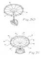
FIG. 1 is a side view drawing of a surgical patient in a laparoscopic procedure;FIG. 2 is a front view drawing of a surgical patient in a "hand-assisted" surgical procedure;FIG. 3 is a front view drawing of a preferred embodiment of the present invention in place;FIG. 4 is an oblique view drawing of the present invention showing two retention members;FIG. 5 is an oblique view drawing of the invention in an alternate embodiment;FIG. 6 shows the present invention having an alternate exterior retention member;FIG. 7A illustrates a folded retention member of the present invention in a closed condition;FIG. 7B illustrates the folded member in an opening condition;FIG. 7C shows the folded member in a half open condition;FIG. 7D shows the folded member in a fully open condition with the seal material tensioned;FIG. 8A illustrates an alternate embodiment of the folded retention member closed;FIG. 8B illustrates the alternate embodiment partially open;FIG. 8C shows the half open retention member having a transverse seal opening;FIG. 8D shows the transverse seal opening fully tensioned along its length;FIG. 9 shows an adjustable external retention member opening the seal portion;FIG. 10 shows the adjustable retention member with a seal portion under minimum tension;FIG. 11 illustrates an adjustable retention having a hinge and jackscrew combination;FIG. 12 shows the hinge and jackscrew placing opening tension on the seal member;FIG. 13 shows the retention member having two jackscrew adjustments and having the seal member in a transverse position and under minimum tension;FIG. 14 shows the retention member where the seal member is under maximum tension;FIG. 15 illustrates an embodiment of the retention member wherein the tensioning of the seal member is provided by detente folding spacers;FIG. 16 shows the detente spacers in an over-center or locked position and applying tension to the seal member;FIG. 17 is an oblique view of the external retention member having a ratchet for holding the seal member at a preferred tension;FIG. 18 illustrates an alternate embodiment of the present invention wherein the external retention member is an un-inflated but inflatable or fillable hollow torrus;FIG. 19 shows the inflatable retention member fully inflated and tensioning the sealing member to provide sealing pressure;FIG. 20 illustrates the present invention having two un-inflated but inflatable retenion members and the seal member at minimum tension;FIG. 21 shows the two inflatable retention members fully inflated and the seal member fully tensioned;FIG. 22 illustrates an alternate embodiment of the present invention where the un-inflated retention members and the seal portion are integrally formed of connected tubular segments;FIG. 23 shows the alternate embodiment in an inflated condition and shaped as would be the case if the device were inserted within a surgical incision;FIG. 24 illustrates an alternate embodiment wherein the external retention member is a coil spring;FIG. 25 illustrates the alternate embodiment wherein the external and the internal retention members are coil springs;FIG. 26 illustrates an alternate embodiment of the present invention wherein a strap is used to maintain a position over a surgical incision;FIG. 27 illustrates an embodiment of the present invention wherein preferred embodiments of the retention member and the seal member are held in place by a strap;FIG. 28 illustrates an additional preferred embodiment of the present invention wherein the sleeve/membrane has tensioning tethers in a first condition;FIG. 29 illustrates the tethers in a second condition;FIG. 30 illustrates the tethers in an irregular, non-uniform configuration;FIG. 31 illustrates the tethers in a regular, uniform configuration; andFIG. 32 is a perspective view of an access device in combination with a stabilizing platform.- In
Fig 1 , a patient is illustrated in a prone or supine position and designated by thereference numeral 10. Thepatient 10 has an abdomen 12 which includes a body orabdominal cavity 16 defined by anabdominal wall 18. A plurality oftrocars abdominal cavity 16. Various instruments 23, 24, 25 are illustrated for use through thetrocars - In
Figure 2 , a "hand-assisted" laparoscopic procedure is shown. Thepatient 10 is supine and theabdominal cavity 16 is insufflated. In addition to thetrocars surgical access device 50 that has been placed relative to asurgical incision 100. Thisaccess device 50 is adapted to receive ahand 160 of a surgeon, as it is placed through theaccess device 50 and into theabdominal cavity 16 of thepatient 10. The surgeon is able to use the insertedhand 160 to perform tasks that are too difficult or not safe for the instruments normally used in laparoscopy. Theaccess device 50 provides a gas tight seal so that the insufflated, pressurized abdomen atcavity 16 does not collapse. Theaccess device 50 may also accommodate large, contaminated specimens or diseased organs or tissue. Furthermore, instrumentation or tools that might otherwise be too large for a trocar may be introduced through theaccess device 50 and subsequently attached to device drivers operated through thetrocars access device 50 when fully burdened. - The
access device 50 is placed through thesurgical incision 100,Figure 3 , and retrained against the external abdominal wall 17 by a first retention member orretainer 55, and against the internalabdominal wall 18 by a second retention member orretainer 65. The external,first retainer 55 supports a gas tight sleeve ormembrane 75 at afirst end 76. The internal,second retainer 65 supports the gas tight sleeve ormembrane 75 at the second,opposite end 86. The two opposing ends 76 and 86 maintain a communicatingsurface 77 that passes through theincision 100. The material of thesurgical access device 50 provides a durable and non-permeable surface against the incised tissue defining theincision 100. - With particular reference to
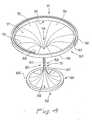
FIGS. 4 ,5, 6 , a preferred embodiment of theaccess device 50 has afirst end 51, asecond end 52 and a communicatingmiddle portion 53. Thefirst end 51, in a preferred embodiment, is external to abody cavity 16 and comprises an enlarged andadjustable portion 55. The exact shape of thefirst end portion 55 may be circular, ovoid, rectangular, square, triangular or the like. Thefirst end portion 55 is sized and configured to be adjustable in area so that asurface 77 of a sleeve ormembrane 75 is appropriately stretched or tensioned. - A preferred embodiment of the
access device 50 employs an overlappingleaf spring 56 that is biased to the open condition. As opposing ends 57, 58 of thespring 56 spread apart, appropriate tension is exerted upon the sleeve/membrane 75. The applied tension causes a pulling force to be exerted through the communicatingmiddle portion 53. This force approximates the second, internal, ordistal end 52 of theaccess device 50 to the inner surface of theabdominal wall 18. - The
second retaining portion 65 is preferably constructed of a flexible material that allows it to be inserted into thesurgical incision 100 in a folded form or reduced profile. Thesecond retaining portion 65 is preferably self-deploying or, at least, has sufficient memory to return to a preferred, somewhat circular, or pre-determined shape or condition without manipulation. The material choices for such a configuration may include flexible vinyl, rubber, silicone, or other elastomeric. The materials may also include rigid materials like rigid plastic or metal with a hinged or flexible portion. - In addition, the construction of either the first or
second retention members second retention member 65 is easily deformable to a condition or shape that facilitates introduction into the smallest possiblesurgical incision 100. It must be kept in mind that thesecond retention member 65 must be sized and configured to retain theaccess device 50 in place during the rigors of an active surgical procedure, and do so without causing tissue damage such as tissue necrosis or abrasion. A preferred embodiment of thesecond retention member 65 comprises aring 66 of soft silicone or vinyl with an internal, encapsulated or insert molded Nickel-Titanium support ring. This embodiment may be introduced in a very deformed condition and will subsequently recover the preferred shape and size upon completion of introduction into thebody cavity 16. - As an alternative, the super-elastic and shape-memory properties of Nickel-Titanium may be drawn from temperature transition properties of the alloy. For instance, the
second retention member 65 may be cooled to a temperature where thering 66 is easily, deformable to a high degree, then, as the alloy warms to body temperature, theretention member 65 returns to a programmed shape, size or configuration. - The sleeve/
membrane portion 75 is shaped by the tension between thefirst retention member 55 and thesecond retention member 65. The sleeve/membrane 75 may initially define anorifice 78 which may be a slit or a hole or the like that communicates between the exterior and the interior of thebody cavity 16 through alumen 80. Thelumen 80 exhibits a first condition when the sleeve/membrane 75 is not under tension and a second condition when the sleeve/membrane 75 is under tension. - In a preferred embodiment, the tensioning of the sleeve/
membrane 75 adjusts thelumen 80 to a preferred size and configuration. Such a configuration might be the creation of the radiused, funnel-shapedorifice 78 transitioning to the smaller diameter in themiddle portion 53 and again transitioning to a funnel-shapedenlargement 67 distally at thesecond retention member 65. - The material of a preferred embodiment of the sleeve/
membrane 75 may include a non-distensible or non-elastic material such as polyethylene, polyurethane or reinforced elastomeric. The choice of polyethylene for the sleeve/membrane 75 provides thesurface 77 with nearly friction-free characteristics against most glove materials. Since the polyethylene material is non-elastic, the sleeve/membrane 75 will fold into discrete "fan-fold"segments 79. Such a condition will allow the material of the sleeve/membrane 75 to be compressed radially by the adjacent body tissue so that it forms athroat 90 or nearly occludedmiddle portion 53 when no hand or instrument is present within thelumen 80 of thedevice 50. Thus, in the absence of the hand or instrument, the throat functions as a zero seal. When a hand or instrument is present within thelumen 80, the fan-folded material at thethroat 90 of the sleeve/membrane 75 yields to the size and shape of the inserted hand or instrument yet forms an occlusive instrument seal. Bearing in mind that the normal pneumoperitoneum is about 18 to .28 psi, thethroat 90 of the present invention is adequate to form both the zero seal and the instrument seal. - The embodiment of
Figure 5 is similar to that ofFigure 4 except that themembrane 75 in proximity to thefirst retention member 55 has the configuration of a septum. In this case, theorifice 78 is formed as a slit which transitions into thethroat 90 of the device.Fan-fold segments 79 extend to the ends of the slit ororifice 78 in this embodiment ofFigure 5 . Thesefan-fold segments 79 are absent in the embodiment ofFigure 6 . - With reference to
FIGS. 7A-D , a preferred embodiment of thesurgical access device 50 of the present invention comprises afirst retention member 155 that is folded so that it resembles a taco. The folding of thefirst retention member 155 relaxes themember 75, allowing thesecond retention member 65 to be easily inserted into a surgical incision 100 (Figure 2 ). The subsequent unfolding of thefirst retention member 155, for example, by forcing apart a pair ofseparable members membrane 75. In this position, the twomembers first retention member 155 are locked in a single plane or flattened condition with the sleeve/membrane 75 in tension. - In a preferred embodiment of the folded
first retention member 155 theorifice 78 is elongate and in line with afold 159 of the sleeve/membrane 75 as well as a pair of hingedportions 158 of thefirst retention member 155. In an alternative embodiment illustrated inFigures 8A-8D , theorifice 78 that is elongate and transverse to both thefold 159 of the sleeve/membrane 75 and the hingedportions 158 of thefirst retention member 155. - With reference to
FIGS. 9-17 , asurgical access device 50 is shown with thefirst retention member 155; however, in this case themember 155 is adjustable in area or circumference. In this embodiment, the twoseparable members first retention member 155 may be separated along a common plane by a pair of actuating adjustingsleeves screws membrane 75 under tension so as to prepare theorifice 78 for use. There may be a several of the adjustingmembers membrane 75. This stretching may be uniform or non-uniform. - Specifically referring to
FIGS. 11, 12 , a further embodiment of thesurgical access device 50 is shown to have at least onehinge 260 that permits theseparate members wheel combination 265. The resulting non-uniform spreading force causes theorifice 78 to assume a preferred condition. - With reference to
FIGS. 13, 14 , there is shown another embodiment of thesurgical access device 50 according to the present invention wherein theelongate orifice 78 is positioned so as to be stretched along itslengthwise midline 278. This configuration causes theorifice 78 to assume a more closed natural condition than would be the case wherein theelongate orifice 78 is transverse to the stretching moment. A combination of in-line and transverse stretching of the sleeve/membrane 75 and theorifice 78 can result in a more symmetrical or uniform opening of theorifice 78. - Referring now to
FIGS. 15, 16 , another embodiment of thesurgical access device 50 is shown, according to the present invention. In this embodiment theseparable members Figure 15 and a contracted position illustrated inFigure 16 . In this case, theseparable member 156 has ends 161 and 163 while theseparable member 157 has ends 160 and 162. Foldedseparation members ends ends separable members separable members ends separable members Figure 15 , theseseparation members Figure 16 . In this condition, theseparation members separable members - An
elongate orifice 78 may be orientated either in-line or transverse to the direction of stretch. An additional embodiment of thesurgical access device 50 may comprise a plurality of thefoldable separation members membrane 75 is more or less uniform. Thefoldable separation members Figure 17 depicts a further embodiment of thesurgical access device 50 according to the present invention. In this case, thefirst retention member 155 comprises a length of rigid or semi-rigid material formed into a hoop orcoil 290. Thiscoil 290 has opposing ends 291 and 292 as well as anouter surface 293 and aninner surface 294. When the ends 291, 292 are spread relative to each other, thecoil 290 assumes a larger diameter and area so that the tension upon the attached sleeve/membrane 75 is increased.- The position of the coil ends 291 and 292 can be maintained by a series of
ratchet teeth 295 and an associatedratchet pawl 296. In the illustrated embodiment, theratchet teeth 295 are formed on theouter surface 293 and theratchet pawl 296 is formed on theend 292. Alternatively, a second series of ratchet teeth can be formed on theinner surface 294, and an associated second ratchet pawl can be formed on theend 291. This double-ended, double-sided ratchet configuration results in a very large distention potential for thefirst retention member 155 and, concomitantly, the sleeve/membrane 75. - In this embodiment, the
first retention member 155, as well as theratchet teeth 295, and theratchet pawl 296, are preferably constructed of a rigid plastic material such as polycabonate, ABS, PBC or other filled or non-filled material. In a further embodiment, thefirst retention member 155 may be formed from a metal so that it is sterilizable and reusable. Such an embodiment may still include the disposable sleeve/membrane 75 and thesecond retention member 65. - With reference now to
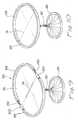
FIGS. 18, 19 ,20, 21 , asurgical access device 50 according to the present invention is shown having an inflatable or fillablefirst retention member 300, and a malleable, foldable or otherwise deformablesecond retention member 65. In a preferred embodiment, the inflatable orfillable retention member 300 comprises a closed,hollow structure 310 which may be circular or toroidal. Thehollow structure 310, when un-inflated or un-filled exerts very little, if any, stretching or tensioning force upon the sleeve/membrane 75. When thehollow structure 310 is inflated, however, it assumes a larger diameter and area which results in the desired stretching or tensioning of the sleeve/membrane 75. Preferred embodiments of thehollow structure 310 can be formed from either elastic or non-distensible materials. - Similarly, the sleeve or
membrane 75 can be formed from an elastic material although in a preferred embodiment themembrane 75 is non-distensible. In this embodiment, expansion of thehollow structure 310 also stretches the sleeve/membrane 75 so that thethroat 90 of theaccess device 50 is also placed under tension. This tensioning ofthroat 90 which connects thefirst retention member 300 and thesecond retention member 65, causes thesecond retention member 65 to be appropriately drawn into sealing engagement with the interior surface of the abdominal wall 18 (Figure 1 ). This will result in a gas-tight seal around theaccess device 50. In the embodiment ofFigure 19 , themembrane 75 is in the form of a septum. - With attention drawn specifically to
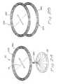
FIGS. 20, 21 , there is shown asurgical access device 50 according to the present invention wherein afirst retention member 300 includes the inflatable orfillable structure 310, and asecond retention member 365 also includes an inflatable orfillable structure 375. Thesecond retention member 365, when un-inflated or un-filled may be easily inserted through anincision 100 into abody cavity 16 and subsequently inflated or filled to assume a more-or-less rigid or definite shape and configuration within thebody cavity 16. Thefirst retention member 300 may then be inflated or filled to provide the external retention and the concurrent stretching or tensioning of the sleeve/membrane 75. Although it is apparent that the sleeve/membrane 75 can also be formed with a double wall structure that is inflatable, this is not the case with the embodiments ofFigure 20 and 21 . In these illustrated embodiments, the sleeve/membrane 75 that connects the two inflatable orfillable retention members membrane 75 is not inflatable and relies on a minimum of intrusive material along the middle portion orthroat 90 and through theincision 100. At thisthroat 90 of theaccess device 50, the sleeve/membrane 75 remains smooth, lubricious, thin, and non-bulky. - An additional embodiment of the
access device 50 of the present invention is shown inFIGS. 22, 23 wherein an open-ended, generallycylindrical sleeve 450 is constructed of a plurality of axially aligned, communicating, hollow, inflatable,fillable members 455. The communicatingmembers 455 are inflatable or fillable by means of aninflation tube 458. Particularly when uninflated, the generally cylindrical shape (Figure 23 ) of theaccess device 450 may be easily distorted so that adistal end 460 may be placed through thesurgical incision 100 and theabdominal cavity 16. As theaccess device 450 is inflated or filled, it assumes an "hourglass" shape, and develops afirst retention portion 470 and a second retention portion 480 joined by amiddle section 490. - A non-distensible or non-elastic material is also stipulated for use in this preferred embodiment so that friction is minimized, and so that the material of the
middle section 490 does not gather or fold as a gloved hand or large instrument is repeatedly inserted and withdrawn through theaccess device 450. - In the illustrated embodiment, the individual inflatable or
fillable members 455 form axial chambers andabutments 495 which prevent material motion and also minimize surface contact between a gloved hand and the material which forms the seal with theabdominal wall 18. The lumen of themiddle section 490 may be lubricated with a thick or viscous material which can be stored along the seams of the abutting or adjoining inflatable orfillable members 455. The lubricating product may also function to perfect the instrument seal in the present of a gloved hand or instrument, or to perfect the zero seal in the absence of the gloved hand or instrument. - With reference to
Figure 24 , asurgical access device 50 according to the present invention is shown wherein a compressiblehelical coil member 500 forms afirst retention member 550. Thecoil member 500 may be deformed so as to minimize the tension upon an attached sleeve/membrane 75 and amiddle portion 560 thereof. Asecond retention member 565 may be deformed and placed within thesurgical incision 100, so that upon release or decompression of thecoil 500 of the first retainingmember 550 thesecond retaining member 565 is appropriately approximated to the interior wall of a body cavity. For packaging and shipping, thecoil 500 of the first retainingmember 550 may be maintained within a containment pouch, bag, box or the like (not shown) in its most-compact condition. In this condition, the first retainingmember 550 will exert a minimum of tension upon the attached sleeve/membrane 75. - In a similar embodiment illustrated in
Figure 25 , asecond retaining member 563 is also provided with a secondretention coil member 565. This secondretaining coil member 565 may be introduced through theincision 100 in a compact configuration and subsequently released to assume an enlarged diameter. This provides theaccess device 50 with an increased area of contact at the inner surface of theabdominal wall 18. As thesecond retention coil 565 is released to assume its enlarged diameter, it also functions to stretch or tension the attached sleeve/membrane 75. - With reference to
FIGS. 26, 27 , there is shown a surgical access device according to the present invention that is adapted to be held in position over thesurgical incision 100 by, a strap orbelt 600 which surrounds the abdomen 12 of the patient 10 (Fig. 1 ). In,this embodiment, theaccess device 50 may include the strap orbelt 600 and associated closure members or buckles 610. Theaccess device 50 in the embodiment ofFigure 26 is illustrated as aseptum seal 615. In the embodiment ofFigure 27 , the access device is similar to that described with reference toFigure 19 and designated with thereference numeral 300. - Turning now to
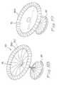
Figures 28 and 29 ; thesurgical access device 50 is shown with amembrane 75 extending between thefirst retention member 55 and thesecond retention member 65. In this embodiment, thefirst retention member 55 includes a solid,rigid ring 700 that is disposed in a plane generally perpendicular to the axis of theaccess device 50. On the side of thering 700 opposite the second retainingportion 65, a plurality ofslits 710 are provided which extend radially of thering 700. In this embodiment, a plurality oftethers 715 are attached to themembrane 75 at different radial locations. Thetethers 715 are attached to themembrane 75 at aninner end 16 and are provided with anenlargement feature 717 at anouter end 718. In this embodiment, theslits 710 of thering 700 are sized and configured to engage and confine at least one of thetethers 715. In such an embodiment, the enlargement features 715 can act to prevent thetethers 715 from being drawn back through theslits 710. Theenlargement feature 717 can also function as handles facilitating engagement of each of thetethers 717, as it is drawn outwardly through the associated slit 710 to tension themembrane 75. - In such an embodiment, it may be desirable to form the
slits 710 so that they are tapered toward the bottom of theslit 710. This will facilitate compression of the associatedtether 715 to increase the frictional engagement between thetether 715 and thering 700. In this manner thetethers 715 can be collectedly adjusted to provide themembrane 75 with the desired shape and seal characteristics. Themembrane 75 can be released from thering 700 by merely lifting thetethers 715 to disengage their associatedslits 710. InFigure 30 , thetether 715 is tensioned non-uniformly to provide themembrane 715 with an irregular shape. This configuration can be compared with that illustrated inFigure 31 wherein the tethers are tensioned uniformly to provide themembrane 75 with a uniform configuration. - In
Figure 32 , theaccess device 50 is illustrated in combination with a stabilizingplatform 800. Initially, it will be noted that theaccess device 50 which is illustrated, is that described generally with reference toFigures 28-31 . However, it will be apparent that the stabilizingplatform 800 can be adapted to receive and function with any of the foregoing embodiments of theaccess device 50, in order to achieve the advantageous discussed below. - In this embodiment, the stabilizing
platform 800 includes a base having a generally planer configuration with a pair ofsupport flanges base 803. A pair of upstanding arms 110 and 112 are pivotally, and perhaps releasably attached to the associatedflanges cross member 814 is pivotally and perhaps releasably connected between thearms cross member 814 in a preferred embodiment is perpendicular to thearms base 803. Theaccess device 50 is supported by thecross member 814, with its axis 816 generally perpendicular to thecross member 814. With this orientation, the first retention member 855, represented by thering 700, is disposed in a plane which may be pivoted relative to theupstanding arms base 803. - In operation, the
base 803 is disposed beneath the patient 10 (Figure 1 ) in contact with the back of thepatient 10. Theupstanding arms flanges patient 10. Thecross member 814 can then be attached to thearms - The
support platform 800 can be of considerable advantage in a hand-assisted laparoscopic procedure which requires that a human hand being inserted and withdrawn several times while maintaining the abdominal pressure or pneumoperitoneum. As noted, the sealing port or throat 90 (Figure 4 ) of theaccess device 50 must tightly fit around the wrist or arm of the surgeon. When the hand of the surgeon is removed, thethroat 90 must close tightly to form a zero seal. This closed sealing attachment to the hand or arm of the surgeon can cause the abdominal wall 18 (Figure 1 ) to change in shape and particularly in elevation as the hand is inserted and removed. If theaccess device 50 is directly attached to theabdominal wall 18, this movement of thewall 18 can result in movement of theaccess device 50 causing other surgical instruments, such as a laparoscope, to be moved or displaced. It is the purpose of the stabilizingplatform 800 to support theaccess device 50 independently of theabdominal wall 18. With this stabilization, movement of the surgeon's hand through theabdominal wall 18 will be less apt to move theaccess device 50. This greatly stabilizes the surgical field and particularly the instruments inserted through theaccess device 50. Appropriate pivoting of thecross member 814 and thearms access device 50 to be swiveled to a position appropriate to patients of various size and weight. In an alternative embodiment, the base may be formed as part of a surgical table with at least one support member, such as thearms 810, 812., extending from one or both sides of the patient to support thecross member 814. - Given the many embodiments disclosed herein for the
access device 50, many other embodiments will now become apparent with changes in structure or materials. For that reason, one is cautioned not to limit the scope of the invention only to the disclosed, embodiments, but only with reference to the following claims.
Claims (4)
- A surgical access device adapted to facilitate access through an incision in a body wall and into a body cavity of a patient, the body wall having an inner surface and an outer surface, the device comprising;
a first retention member sized and configured to surround the incision in proximity to the outer surface of the body wall;
a second retention member sized and configured to surround the incision in proximity to the inner surface of the body wall;
a membrane extending between the first retention member and the second retention member, the membrane forming a working channel adapted for disposition through the incision,
a plurality of retention stations disposed on a ring of the first retention member; and
a plurality of tethers coupling the membrane to the ring, each of the tethers releasably engaging an associated one of the retention stations at a particular position along the tether providing the membrane with a desired shape. - The access device recited in Claim 1, wherein at least one of the retention stations includes portions of the ring defining a groove sized and configured to receive and releasably hold the associated tether at the particular position along the tether.
- The surgical access device recited in Claim 2, wherein the groove is generally V-shaped.
- The surgical access device recited in any preceding claim, further comprising:at least one strap fixed to the first retention member, the strap being sized and configured for disposition around the patient to hold the first retention member in proximity to the outer surface of the body wall.
Applications Claiming Priority (2)
| Application Number | Priority Date | Filing Date | Title |
|---|---|---|---|
| PCT/US2001/050160WO2003034908A2 (en) | 2001-10-20 | 2001-10-20 | Sealed surgical access device |
| EP01985127AEP1441636B1 (en) | 2001-10-20 | 2001-10-20 | Sealed surgical access device |
Related Parent Applications (1)
| Application Number | Title | Priority Date | Filing Date |
|---|---|---|---|
| EP01985127.8Division | 2001-10-20 |
Publications (2)
| Publication Number | Publication Date |
|---|---|
| EP2374402A1true EP2374402A1 (en) | 2011-10-12 |
| EP2374402B1 EP2374402B1 (en) | 2012-05-09 |
Family
ID=21743165
Family Applications (3)
| Application Number | Title | Priority Date | Filing Date |
|---|---|---|---|
| EP01985127AExpired - LifetimeEP1441636B1 (en) | 2001-10-20 | 2001-10-20 | Sealed surgical access device |
| EP11172706AExpired - LifetimeEP2374402B1 (en) | 2001-10-20 | 2001-10-20 | Sealed surgical access device |
| EP11172709AExpired - LifetimeEP2374403B1 (en) | 2001-10-20 | 2001-10-20 | Sealed surgical access device |
Family Applications Before (1)
| Application Number | Title | Priority Date | Filing Date |
|---|---|---|---|
| EP01985127AExpired - LifetimeEP1441636B1 (en) | 2001-10-20 | 2001-10-20 | Sealed surgical access device |
Family Applications After (1)
| Application Number | Title | Priority Date | Filing Date |
|---|---|---|---|
| EP11172709AExpired - LifetimeEP2374403B1 (en) | 2001-10-20 | 2001-10-20 | Sealed surgical access device |
Country Status (4)
| Country | Link |
|---|---|
| EP (3) | EP1441636B1 (en) |
| JP (1) | JP4460293B2 (en) |
| CA (1) | CA2426481A1 (en) |
| WO (1) | WO2003034908A2 (en) |
Cited By (2)
| Publication number | Priority date | Publication date | Assignee | Title |
|---|---|---|---|---|
| US9320508B2 (en) | 2014-02-27 | 2016-04-26 | Gyrus Acmi, Inc. | Expandable medical access sheath |
| WO2020005218A1 (en) | 2018-06-27 | 2020-01-02 | Wright Medical Technology, Inc. | Burr with irrigation and imaging |
Families Citing this family (101)
| Publication number | Priority date | Publication date | Assignee | Title |
|---|---|---|---|---|
| US5989224A (en) | 1998-02-23 | 1999-11-23 | Dexide Corporation | Universal seal for use with endoscopic cannula |
| US6254534B1 (en) | 1999-10-14 | 2001-07-03 | Atropos Limited | Retractor |
| US7537564B2 (en) | 1998-12-01 | 2009-05-26 | Atropos Limited | Wound retractor device |
| US7559893B2 (en) | 1998-12-01 | 2009-07-14 | Atropos Limited | Wound retractor device |
| US7998068B2 (en) | 1998-12-01 | 2011-08-16 | Atropos Limited | Instrument access device |
| CN100512766C (en) | 1998-12-01 | 2009-07-15 | 阿特波斯有限公司 | A surgical device for retracting and/or sealing an incision |
| US7540839B2 (en) | 1999-10-14 | 2009-06-02 | Atropos Limited | Wound retractor |
| JP5190169B2 (en) | 2000-10-19 | 2013-04-24 | アプライド メディカル リソーシーズ コーポレイション | Surgical access instruments and methods |
| EP2422829B1 (en) | 2001-08-14 | 2013-03-06 | Applied Medical Resources Corporation | Surgical access sealing apparatus |
| US6958037B2 (en) | 2001-10-20 | 2005-10-25 | Applied Medical Resources Corporation | Wound retraction apparatus and method |
| EP2343032B1 (en) | 2002-06-05 | 2012-05-09 | Applied Medical Resources Corporation | Wound retractor |
| US9271753B2 (en) | 2002-08-08 | 2016-03-01 | Atropos Limited | Surgical device |
| DE60314464T2 (en) | 2002-09-19 | 2008-02-14 | Atropos Ltd., Bray | SURGICAL WOUND RETRACTOR |
| US7323004B2 (en) | 2002-09-30 | 2008-01-29 | Ethicon, Inc. | Device for providing automatic stitching of an incision |
| US7217277B2 (en) | 2002-09-30 | 2007-05-15 | Ethicon, Inc. | Device for providing intracardiac access in an open chest |
| US20050020884A1 (en) | 2003-02-25 | 2005-01-27 | Hart Charles C. | Surgical access system |
| CA2533204A1 (en) | 2003-08-06 | 2005-02-17 | Applied Medical Resources Corporation | Surgical device with tack-free gel and method of manufacture |
| US7163510B2 (en) | 2003-09-17 | 2007-01-16 | Applied Medical Resources Corporation | Surgical instrument access device |
| JP2009501045A (en) | 2005-07-15 | 2009-01-15 | アトロポス・リミテッド | Wound retractor |
| AU2006304141B2 (en) | 2005-10-14 | 2012-07-05 | Applied Medical Resources Corporation | Gel cap for wound retractor |
| DE102006015690A1 (en)* | 2006-03-27 | 2007-10-11 | Aesculap Ag & Co. Kg | Surgical sealing element, surgical seal and surgical sealing system |
| JP5191998B2 (en)* | 2007-02-22 | 2013-05-08 | エシコン・エンド−サージェリィ・インコーポレイテッド | Throttle valve with new locking mechanism and control ring |
| WO2008141291A1 (en) | 2007-05-11 | 2008-11-20 | Applied Medical Resources Corporation | Surgical retractor with gel pad |
| US8133174B2 (en)* | 2007-05-30 | 2012-03-13 | Tyco Healthcare Group Lp | Self constricting orifice seal |
| WO2008149332A1 (en) | 2007-06-05 | 2008-12-11 | Atropos Limited | An instrument access device |
| US8657740B2 (en) | 2007-06-05 | 2014-02-25 | Atropos Limited | Instrument access device |
| US20090093752A1 (en) | 2007-10-05 | 2009-04-09 | Tyco Healthcare Group Lp | Seal anchor for use in surgical procedures |
| US9028448B2 (en) | 2008-06-19 | 2015-05-12 | Covidien Lp | Access seal with interstitial channels |
| USD738500S1 (en) | 2008-10-02 | 2015-09-08 | Covidien Lp | Seal anchor for use in surgical procedures |
| KR101829726B1 (en) | 2008-10-10 | 2018-02-19 | 서지퀘스트, 인코포레이티드 | Low-profile surgical access devices with anchoring |
| CA2739910C (en) | 2008-10-13 | 2017-06-06 | Applied Medical Resources Corporation | Single port access system |
| US8375955B2 (en) | 2009-02-06 | 2013-02-19 | Atropos Limited | Surgical procedure |
| EP4154824B1 (en)* | 2009-07-21 | 2024-09-04 | Applied Medical Resources Corporation | Surgical access device comprising internal retractor |
| CA2771337C (en) | 2009-08-31 | 2018-05-01 | Jeremy J. Albrecht | Multifunctional surgical access system |
| WO2011033495A1 (en) | 2009-09-17 | 2011-03-24 | Atropos Limited | An instrument access device |
| US8920314B2 (en)* | 2009-10-07 | 2014-12-30 | Covidien Lp | Universal height foam port |
| US8777849B2 (en) | 2010-02-12 | 2014-07-15 | Covidien Lp | Expandable thoracic access port |
| US8597180B2 (en)* | 2010-08-12 | 2013-12-03 | Covidien Lp | Expandable thoracic access port |
| US9247955B2 (en)* | 2010-08-12 | 2016-02-02 | Covidien Lp | Thoracic access port |
| US8864658B2 (en) | 2010-08-12 | 2014-10-21 | Covidien Lp | Expandable surgical access port |
| US8961408B2 (en) | 2010-08-12 | 2015-02-24 | Covidien Lp | Expandable surgical access port |
| JP6396657B2 (en) | 2010-10-01 | 2018-09-26 | アプライド メディカル リソーシーズ コーポレイション | Natural orifice surgery system |
| US9289115B2 (en) | 2010-10-01 | 2016-03-22 | Applied Medical Resources Corporation | Natural orifice surgery system |
| US8864659B2 (en) | 2010-11-23 | 2014-10-21 | Covidien Lp | Seal anchor for use in surgical procedures |
| US8727974B2 (en)* | 2010-11-24 | 2014-05-20 | Covidien Lp | Access assembly including one or more compressible vents |
| US20120157782A1 (en) | 2010-12-20 | 2012-06-21 | Francesco Alfieri | Hand access device |
| US8550992B2 (en) | 2010-12-20 | 2013-10-08 | Covidien Lp | Two-part access assembly |
| US8888691B2 (en) | 2011-01-24 | 2014-11-18 | Covidien Lp | Expanding surgical access port |
| US8753267B2 (en) | 2011-01-24 | 2014-06-17 | Covidien Lp | Access assembly insertion device |
| US9022928B2 (en) | 2011-03-18 | 2015-05-05 | Covidien Lp | Wound protector including balloon within incision |
| US9119665B2 (en) | 2011-03-21 | 2015-09-01 | Covidien Lp | Thoracic access port including foldable anchor |
| US8758236B2 (en)* | 2011-05-10 | 2014-06-24 | Applied Medical Resources Corporation | Wound retractor |
| US9039610B2 (en) | 2011-05-19 | 2015-05-26 | Covidien Lp | Thoracic access port |
| GB2495534B (en)* | 2011-10-13 | 2014-04-23 | Neosurgical Ltd | Laparoscopic system |
| CA2797624A1 (en) | 2011-12-07 | 2013-06-07 | Covidien Lp | Thoracic access assembly |
| WO2013106347A1 (en)* | 2012-01-10 | 2013-07-18 | The Board Of Trustees Of The Leland Stanford Junior University | Methods and devices for the prevention of surgical site infections |
| US9271639B2 (en) | 2012-02-29 | 2016-03-01 | Covidien Lp | Surgical introducer and access port assembly |
| ES2806266T3 (en) | 2013-03-15 | 2021-02-17 | Applied Med Resources | Trocar Surgical Seal Gasket |
| JP2016512725A (en) | 2013-03-15 | 2016-05-09 | アプライド メディカル リソーシーズ コーポレイション | Mechanical gel surgical access instrument |
| US10064649B2 (en) | 2014-07-07 | 2018-09-04 | Covidien Lp | Pleated seal for surgical hand or instrument access |
| EP3169510B1 (en) | 2014-07-18 | 2018-10-03 | Applied Medical Resources Corporation | Method for manufacturing gels having permanent tack free coatings |
| KR20240172766A (en) | 2014-08-15 | 2024-12-10 | 어플라이드 메디컬 리소시스 코포레이션 | Natural orifice surgery system |
| US9707011B2 (en) | 2014-11-12 | 2017-07-18 | Covidien Lp | Attachments for use with a surgical access device |
| CA2967766C (en)* | 2014-11-13 | 2023-10-17 | Applied Medical Resources Corporation | Systems and methods for tissue removal |
| WO2016085930A2 (en) | 2014-11-25 | 2016-06-02 | Applied Medical Resources Corporation | Circumferential wound retraction with support and guidance structures |
| JP6292141B2 (en) | 2015-01-29 | 2018-03-14 | 独立行政法人国立病院機構 | Retractor |
| US10368908B2 (en) | 2015-09-15 | 2019-08-06 | Applied Medical Resources Corporation | Surgical robotic access system |
| WO2017062850A2 (en) | 2015-10-07 | 2017-04-13 | Applied Medical Resources Corporation | Wound retractor with multi-segment outer ring |
| CN107019564A (en)* | 2016-01-29 | 2017-08-08 | 邵贤斌 | Wound protector |
| AU2017324450B2 (en) | 2016-09-12 | 2022-09-29 | Applied Medical Resources Corporation | Surgical robotic access system for irregularly shaped robotic actuators and associated robotic surgical instruments |
| US10987128B2 (en) | 2017-03-22 | 2021-04-27 | Covidien Lp | Cannula assembly |
| US11160682B2 (en) | 2017-06-19 | 2021-11-02 | Covidien Lp | Method and apparatus for accessing matter disposed within an internal body vessel |
| US10828065B2 (en) | 2017-08-28 | 2020-11-10 | Covidien Lp | Surgical access system |
| US10675056B2 (en) | 2017-09-07 | 2020-06-09 | Covidien Lp | Access apparatus with integrated fluid connector and control valve |
| WO2019094502A1 (en) | 2017-11-07 | 2019-05-16 | Prescient Surgical, Inc. | Methods and apparatus for prevention of surgical site infection |
| US11389193B2 (en) | 2018-10-02 | 2022-07-19 | Covidien Lp | Surgical access device with fascial closure system |
| US11457949B2 (en) | 2018-10-12 | 2022-10-04 | Covidien Lp | Surgical access device and seal guard for use therewith |
| US10792071B2 (en) | 2019-02-11 | 2020-10-06 | Covidien Lp | Seals for surgical access assemblies |
| US11166748B2 (en) | 2019-02-11 | 2021-11-09 | Covidien Lp | Seal assemblies for surgical access assemblies |
| US11000313B2 (en) | 2019-04-25 | 2021-05-11 | Covidien Lp | Seals for surgical access devices |
| US11413068B2 (en) | 2019-05-09 | 2022-08-16 | Covidien Lp | Seal assemblies for surgical access assemblies |
| US11259841B2 (en) | 2019-06-21 | 2022-03-01 | Covidien Lp | Seal assemblies for surgical access assemblies |
| US11357542B2 (en) | 2019-06-21 | 2022-06-14 | Covidien Lp | Valve assembly and retainer for surgical access assembly |
| US11259840B2 (en) | 2019-06-21 | 2022-03-01 | Covidien Lp | Valve assemblies for surgical access assemblies |
| US11413065B2 (en) | 2019-06-28 | 2022-08-16 | Covidien Lp | Seal assemblies for surgical access assemblies |
| US11399865B2 (en) | 2019-08-02 | 2022-08-02 | Covidien Lp | Seal assemblies for surgical access assemblies |
| US11523842B2 (en) | 2019-09-09 | 2022-12-13 | Covidien Lp | Reusable surgical port with disposable seal assembly |
| US11432843B2 (en) | 2019-09-09 | 2022-09-06 | Covidien Lp | Centering mechanisms for a surgical access assembly |
| US11812991B2 (en) | 2019-10-18 | 2023-11-14 | Covidien Lp | Seal assemblies for surgical access assemblies |
| US11141191B2 (en) | 2020-01-15 | 2021-10-12 | Covidien Lp | Surgical access assembly |
| US11464540B2 (en) | 2020-01-17 | 2022-10-11 | Covidien Lp | Surgical access device with fixation mechanism |
| US12324606B2 (en) | 2020-01-28 | 2025-06-10 | Covidien Lp | Seal assemblies for surgical access assemblies |
| US11576701B2 (en) | 2020-03-05 | 2023-02-14 | Covidien Lp | Surgical access assembly having a pump |
| US11446058B2 (en) | 2020-03-27 | 2022-09-20 | Covidien Lp | Fixture device for folding a seal member |
| US11717321B2 (en) | 2020-04-24 | 2023-08-08 | Covidien Lp | Access assembly with retention mechanism |
| US11529170B2 (en) | 2020-04-29 | 2022-12-20 | Covidien Lp | Expandable surgical access port |
| US11622790B2 (en) | 2020-05-21 | 2023-04-11 | Covidien Lp | Obturators for surgical access assemblies and methods of assembly thereof |
| US11751908B2 (en) | 2020-06-19 | 2023-09-12 | Covidien Lp | Seal assembly for surgical access assemblies |
| WO2022150592A1 (en)* | 2021-01-10 | 2022-07-14 | Ma Eric Hsinhua | Neutron capture therapy system and device |
| US12251130B2 (en) | 2021-05-03 | 2025-03-18 | Covidien Lp | Surgical access device having a balloon and methods for manufacturing the same |
| JP7373609B1 (en) | 2022-06-02 | 2023-11-02 | 理恵 松下 | retractor |
Citations (6)
| Publication number | Priority date | Publication date | Assignee | Title |
|---|---|---|---|---|
| US5197955A (en)* | 1991-10-18 | 1993-03-30 | Ethicon, Inc. | Universal seal for trocar assembly |
| US5460170A (en)* | 1994-08-23 | 1995-10-24 | Hammerslag; Julius G. | Adjustable surgical retractor |
| US5514133A (en)* | 1994-08-26 | 1996-05-07 | Golub; Robert | Access device for endoscopic surgery |
| US5741234A (en)* | 1996-07-16 | 1998-04-21 | Aboul-Hosn; Walid Nagib | Anatomical cavity access sealing condit |
| US5848992A (en) | 1997-03-07 | 1998-12-15 | Hart; Charles C. | Superfascial surgical access device |
| WO2000032116A1 (en)* | 1998-12-01 | 2000-06-08 | Atropos Limited | A surgical device for retracting and/or sealing an incision |
Family Cites Families (14)
| Publication number | Priority date | Publication date | Assignee | Title |
|---|---|---|---|---|
| US4984564A (en)* | 1989-09-27 | 1991-01-15 | Frank Yuen | Surgical retractor device |
| US5653705A (en)* | 1994-10-07 | 1997-08-05 | General Surgical Innovations, Inc. | Laparoscopic access port for surgical instruments or the hand |
| US5741298A (en)* | 1995-04-28 | 1998-04-21 | Macleod; Cathel | Method and devices for video-assisted surgical techniques |
| AU2064797A (en)* | 1996-03-04 | 1997-09-22 | Heartport, Inc. | Retractor for providing surgical access and suture organizer |
| DE69634385D1 (en)* | 1996-05-10 | 2005-03-31 | Emmanuil Giannadakis | SYSTEM FOR LAPAROSCOPIC AND ENDOSCOPIC SURGERY |
| JP2957134B2 (en)* | 1996-10-08 | 1999-10-04 | 株式会社八光電機製作所 | Valve and valved trocar mantle |
| US5906577A (en)* | 1997-04-30 | 1999-05-25 | University Of Massachusetts | Device, surgical access port, and method of retracting an incision into an opening and providing a channel through the incision |
| JPH1199156A (en)* | 1997-07-29 | 1999-04-13 | Olympus Optical Co Ltd | Access device for surgical treatment |
| US6254534B1 (en)* | 1999-10-14 | 2001-07-03 | Atropos Limited | Retractor |
| HK1040604B (en) | 1998-12-02 | 2006-02-03 | Mdz Beheer B.V. | Brush suitable for taking a smear |
| IES990220A2 (en)* | 1999-03-18 | 2000-11-15 | Gaya Ltd | A surgical device |
| US6171282B1 (en)* | 1999-07-23 | 2001-01-09 | Edgar K. Ragsdale | Soft cannula and methods for use |
| IE990795A1 (en)* | 1999-07-30 | 2001-03-07 | Gaya Ltd | Hand Access Port Device |
| US6383162B1 (en)* | 1999-11-12 | 2002-05-07 | Paul H. Sugarbaker | Apparatus and method for abdomino-pelvic chemotherapy perfusion and lavage |
- 2001
- 2001-10-20EPEP01985127Apatent/EP1441636B1/ennot_activeExpired - Lifetime
- 2001-10-20JPJP2003537484Apatent/JP4460293B2/ennot_activeExpired - Lifetime
- 2001-10-20EPEP11172706Apatent/EP2374402B1/ennot_activeExpired - Lifetime
- 2001-10-20EPEP11172709Apatent/EP2374403B1/ennot_activeExpired - Lifetime
- 2001-10-20CACA002426481Apatent/CA2426481A1/ennot_activeAbandoned
- 2001-10-20WOPCT/US2001/050160patent/WO2003034908A2/enactiveApplication Filing
Patent Citations (6)
| Publication number | Priority date | Publication date | Assignee | Title |
|---|---|---|---|---|
| US5197955A (en)* | 1991-10-18 | 1993-03-30 | Ethicon, Inc. | Universal seal for trocar assembly |
| US5460170A (en)* | 1994-08-23 | 1995-10-24 | Hammerslag; Julius G. | Adjustable surgical retractor |
| US5514133A (en)* | 1994-08-26 | 1996-05-07 | Golub; Robert | Access device for endoscopic surgery |
| US5741234A (en)* | 1996-07-16 | 1998-04-21 | Aboul-Hosn; Walid Nagib | Anatomical cavity access sealing condit |
| US5848992A (en) | 1997-03-07 | 1998-12-15 | Hart; Charles C. | Superfascial surgical access device |
| WO2000032116A1 (en)* | 1998-12-01 | 2000-06-08 | Atropos Limited | A surgical device for retracting and/or sealing an incision |
Cited By (4)
| Publication number | Priority date | Publication date | Assignee | Title |
|---|---|---|---|---|
| US9320508B2 (en) | 2014-02-27 | 2016-04-26 | Gyrus Acmi, Inc. | Expandable medical access sheath |
| US10426451B2 (en) | 2014-02-27 | 2019-10-01 | Gyrus Acmi, Inc. | Expandable medical access sheath |
| WO2020005218A1 (en) | 2018-06-27 | 2020-01-02 | Wright Medical Technology, Inc. | Burr with irrigation and imaging |
| EP3813691A4 (en)* | 2018-06-27 | 2022-03-30 | Wright Medical Technology, Inc. | Burr with irrigation and imaging |
Also Published As
| Publication number | Publication date |
|---|---|
| EP2374403B1 (en) | 2013-04-03 |
| WO2003034908A2 (en) | 2003-05-01 |
| EP2374403A1 (en) | 2011-10-12 |
| CA2426481A1 (en) | 2003-05-01 |
| EP1441636A2 (en) | 2004-08-04 |
| WO2003034908A3 (en) | 2003-06-05 |
| EP1441636B1 (en) | 2012-01-11 |
| JP2005506144A (en) | 2005-03-03 |
| EP1441636A4 (en) | 2009-05-27 |
| JP4460293B2 (en) | 2010-05-12 |
| EP2374402B1 (en) | 2012-05-09 |
Similar Documents
| Publication | Publication Date | Title |
|---|---|---|
| EP2374403B1 (en) | Sealed surgical access device | |
| US7052454B2 (en) | Sealed surgical access device | |
| JP4148973B2 (en) | Hermetic surgical access device | |
| WO2004075730A2 (en) | Sealed surgical access device | |
| JP5830318B2 (en) | Seal port with adjustable height | |
| US9295459B2 (en) | Surgical access system | |
| EP1620019B1 (en) | Balloon dissector with balloon anchor cannula | |
| US5964781A (en) | Skin seal with inflatable membrane | |
| EP2609879B1 (en) | Surgical access assembly | |
| EP2238924A1 (en) | Foam port and introducer assembly | |
| CA2312801A1 (en) | Seal member for surgical trocar |
Legal Events
| Date | Code | Title | Description |
|---|---|---|---|
| PUAI | Public reference made under article 153(3) epc to a published international application that has entered the european phase | Free format text:ORIGINAL CODE: 0009012 | |
| 17P | Request for examination filed | Effective date:20110705 | |
| AC | Divisional application: reference to earlier application | Ref document number:1441636 Country of ref document:EP Kind code of ref document:P | |
| AK | Designated contracting states | Kind code of ref document:A1 Designated state(s):DE FR GB | |
| GRAP | Despatch of communication of intention to grant a patent | Free format text:ORIGINAL CODE: EPIDOSNIGR1 | |
| RIC1 | Information provided on ipc code assigned before grant | Ipc:A61B 17/34 20060101ALI20111110BHEP Ipc:A61B 1/32 20060101AFI20111110BHEP | |
| GRAS | Grant fee paid | Free format text:ORIGINAL CODE: EPIDOSNIGR3 | |
| RIN1 | Information on inventor provided before grant (corrected) | Inventor name:MORALES, NORMAN Inventor name:HART, CHARLES C. Inventor name:DULAK, GARY R. Inventor name:BRUSTAD, JOHN R. Inventor name:PINGELTON, EDWARD D. Inventor name:HILAL, NABIL Inventor name:ADLPARVAR, PAYAM Inventor name:EWERS, RICHARD C. Inventor name:TAYLOR, SCOTT Inventor name:DUNN, MICHAEL J. | |
| GRAA | (expected) grant | Free format text:ORIGINAL CODE: 0009210 | |
| AC | Divisional application: reference to earlier application | Ref document number:1441636 Country of ref document:EP Kind code of ref document:P | |
| AK | Designated contracting states | Kind code of ref document:B1 Designated state(s):DE FR GB | |
| REG | Reference to a national code | Ref country code:GB Ref legal event code:FG4D | |
| REG | Reference to a national code | Ref country code:DE Ref legal event code:R096 Ref document number:60146573 Country of ref document:DE Effective date:20120705 | |
| PLBE | No opposition filed within time limit | Free format text:ORIGINAL CODE: 0009261 | |
| STAA | Information on the status of an ep patent application or granted ep patent | Free format text:STATUS: NO OPPOSITION FILED WITHIN TIME LIMIT | |
| 26N | No opposition filed | Effective date:20130212 | |
| REG | Reference to a national code | Ref country code:DE Ref legal event code:R097 Ref document number:60146573 Country of ref document:DE Effective date:20130212 | |
| REG | Reference to a national code | Ref country code:FR Ref legal event code:PLFP Year of fee payment:15 | |
| REG | Reference to a national code | Ref country code:FR Ref legal event code:PLFP Year of fee payment:16 | |
| REG | Reference to a national code | Ref country code:FR Ref legal event code:PLFP Year of fee payment:17 | |
| PGFP | Annual fee paid to national office [announced via postgrant information from national office to epo] | Ref country code:FR Payment date:20171025 Year of fee payment:17 Ref country code:DE Payment date:20171027 Year of fee payment:17 | |
| PGFP | Annual fee paid to national office [announced via postgrant information from national office to epo] | Ref country code:GB Payment date:20171027 Year of fee payment:17 | |
| REG | Reference to a national code | Ref country code:DE Ref legal event code:R119 Ref document number:60146573 Country of ref document:DE | |
| GBPC | Gb: european patent ceased through non-payment of renewal fee | Effective date:20181020 | |
| PG25 | Lapsed in a contracting state [announced via postgrant information from national office to epo] | Ref country code:DE Free format text:LAPSE BECAUSE OF NON-PAYMENT OF DUE FEES Effective date:20190501 | |
| PG25 | Lapsed in a contracting state [announced via postgrant information from national office to epo] | Ref country code:FR Free format text:LAPSE BECAUSE OF NON-PAYMENT OF DUE FEES Effective date:20181031 | |
| PG25 | Lapsed in a contracting state [announced via postgrant information from national office to epo] | Ref country code:GB Free format text:LAPSE BECAUSE OF NON-PAYMENT OF DUE FEES Effective date:20181020 | |
| P01 | Opt-out of the competence of the unified patent court (upc) registered | Effective date:20230524 |