EP2373916B1 - Security device and system for monitoring pipes - Google Patents
Security device and system for monitoring pipesDownload PDFInfo
- Publication number
- EP2373916B1 EP2373916B1EP09795325AEP09795325AEP2373916B1EP 2373916 B1EP2373916 B1EP 2373916B1EP 09795325 AEP09795325 AEP 09795325AEP 09795325 AEP09795325 AEP 09795325AEP 2373916 B1EP2373916 B1EP 2373916B1
- Authority
- EP
- European Patent Office
- Prior art keywords
- security device
- arrangement
- pipe
- borne sound
- designed
- Prior art date
- Legal status (The legal status is an assumption and is not a legal conclusion. Google has not performed a legal analysis and makes no representation as to the accuracy of the status listed.)
- Active
Links
- 238000012544monitoring processMethods0.000titleclaimsdescription9
- 239000004020conductorSubstances0.000claimsdescription12
- 238000006073displacement reactionMethods0.000claimsdescription9
- 239000012528membraneSubstances0.000claimsdescription9
- 238000012545processingMethods0.000claimsdescription8
- 230000006854communicationEffects0.000claimsdescription7
- 238000004891communicationMethods0.000claimsdescription7
- 238000005520cutting processMethods0.000claimsdescription4
- 229920002635polyurethanePolymers0.000claimsdescription3
- 239000004814polyurethaneSubstances0.000claimsdescription3
- 230000007797corrosionEffects0.000claimsdescription2
- 238000005260corrosionMethods0.000claimsdescription2
- 230000000694effectsEffects0.000claimsdescription2
- 150000003839saltsChemical class0.000claimsdescription2
- 238000004458analytical methodMethods0.000claims2
- 238000001514detection methodMethods0.000description15
- 235000014676Phragmites communisNutrition0.000description6
- 238000003860storageMethods0.000description5
- 230000008878couplingEffects0.000description4
- 238000010168coupling processMethods0.000description4
- 238000005859coupling reactionMethods0.000description4
- 238000004146energy storageMethods0.000description4
- 230000006870functionEffects0.000description4
- 230000005291magnetic effectEffects0.000description4
- 238000010276constructionMethods0.000description3
- 238000011156evaluationMethods0.000description3
- 239000000463materialSubstances0.000description3
- 238000011161developmentMethods0.000description2
- 230000018109developmental processEffects0.000description2
- 230000007613environmental effectEffects0.000description2
- 238000004519manufacturing processMethods0.000description2
- 239000002184metalSubstances0.000description2
- 238000007789sealingMethods0.000description2
- 238000010521absorption reactionMethods0.000description1
- 230000001133accelerationEffects0.000description1
- 230000002411adverseEffects0.000description1
- 230000000712assemblyEffects0.000description1
- 238000000429assemblyMethods0.000description1
- 230000007175bidirectional communicationEffects0.000description1
- 238000006243chemical reactionMethods0.000description1
- 230000000295complement effectEffects0.000description1
- 238000013016dampingMethods0.000description1
- 230000001419dependent effectEffects0.000description1
- 238000005553drillingMethods0.000description1
- 230000005294ferromagnetic effectEffects0.000description1
- 238000009434installationMethods0.000description1
- 238000012423maintenanceMethods0.000description1
- BASFCYQUMIYNBI-UHFFFAOYSA-NplatinumChemical compound[Pt]BASFCYQUMIYNBI-UHFFFAOYSA-N0.000description1
- 230000000630rising effectEffects0.000description1
- 230000035945sensitivityEffects0.000description1
- 238000005476solderingMethods0.000description1
- 239000007787solidSubstances0.000description1
- 230000003319supportive effectEffects0.000description1
- 230000001960triggered effectEffects0.000description1
- 238000003466weldingMethods0.000description1
Images


Classifications
- F—MECHANICAL ENGINEERING; LIGHTING; HEATING; WEAPONS; BLASTING
- F17—STORING OR DISTRIBUTING GASES OR LIQUIDS
- F17D—PIPE-LINE SYSTEMS; PIPE-LINES
- F17D5/00—Protection or supervision of installations
- F—MECHANICAL ENGINEERING; LIGHTING; HEATING; WEAPONS; BLASTING
- F17—STORING OR DISTRIBUTING GASES OR LIQUIDS
- F17D—PIPE-LINE SYSTEMS; PIPE-LINES
- F17D5/00—Protection or supervision of installations
- F17D5/02—Preventing, monitoring, or locating loss
- F17D5/06—Preventing, monitoring, or locating loss using electric or acoustic means
Definitions
- the present inventionrelates to a safety device for a covering device of a pipe and / or pipe, which is usable with a number of other pipes in preferably welded together form for the production of pipelines, wherein the covering comprises a sleeve covering an inner wall of the tube and the safety device is designed to generate an alarm signal. Furthermore, the invention relates to a system for monitoring pipes.
- Pipes used for pipeline constructionmust meet the highest quality standards.
- the media to be transported through the pipelines, such as oil,can cause serious damage to the environment if improperly assembled. In addition, such damage leads to high financial burdens on the companies operating the pipeline.
- Prior to installation in an existing pipeline or before assembling several pipes to form a pipelinethe edges and weld areas of the pipes must be particularly well protected.
- covering devicesare used, in particular also parts of the inner wall located in the ends of the tube by means of a sleeve or the like. caulk.
- the transport and storage of the pipesshould be monitored until assembly.
- EP 1 229 173 A1A known from the prior art closure device for pipelines is for example the EP 1 229 173 A1 refer to.
- the safety devicecomprises a structure-borne noise sensor comprising a structure-borne sound detection device for detecting manipulations on the pipe.
- Manipulations on the pipefor example, are accompanied by knocking or welding noises and, as a result, a characteristic structure-borne noise. Even accidental dropping of the tube during its transport generates structure-borne noise in the pipe. Different structure-borne noise can thus be assigned to characteristic causes.
- a safety device having a structure-borne sound detection device with a structure-borne sound sensorcan record the structure-borne noise that occurs in the pipe and - preferably in an electronically assisted evaluation - cause the issuing of an alarm signal.
- the structure-borne noise detection devicemay comprise suitable means for evaluating the signal received by the sensor.
- the structure-borne sound detection deviceis advantageously adapted to the rounding of the inside of the pipe.
- the structure-borne sound detection deviceis provided with a piezoelectric element which serves to record the structure-borne noise and its conversion into electrical impulses.
- the piezo elementis thus in particular part of the structure-borne sound sensor.
- the piezoelectric elementmay be partially freely swinging, for example in the manner of a tuning fork.
- an embodiment in which the piezoelectric element or another structure-borne noise sensor is arranged on a vibrating body, which is tuned in particular by its natural frequency to the frequency range of the structure-borne sound to be detectedis preferred.
- the oscillating bodycan be, for example, a metal strip whose shape and dimensions (for example, length, width, height) are matched to the structure-borne sound to be recorded.
- the vibrating body of the structure-borne noise detection device or the safety deviceis to bring indirectly or directly into contact with the inside of the tube wall to record the structure-borne sound and forward to the piezoelectric element or deliver.
- the sounds to be detectedare generally not a single frequency but a plurality of frequencies or a frequency band which is generated, for example, by drilling or knocking on the tube.
- thisis a frequency range between 10 and 20 kHz, in which the vibrating body also has a natural frequency.
- the structure-borne sound sensor or the piezoelectric elementWhen using a vibrating body with a tuned Figenfrequenz is particularly advantageous that the structure-borne sound sensor or the piezoelectric element must not be in direct contact with the inner wall of the pipe. It can be arranged appropriately protected. Due to the tuning of the vibrating body nevertheless a high sensitivity of the structure-borne noise detection device is ensured. Furthermore, the piezoelectric element and the oscillating body, if they are cast in a material for example, are adapted to the damping by this material.
- the oscillating body itselfcan be attached using at least one magnet to the inner wall of the pipe to be monitored.
- the structure-borne sound detection devicecomprises at least one magnet for holding at least a part of the structure-borne noise detection device on the pipe to be monitored.
- the tubeis not part of the invention.
- the magnetic coupling forcecan be enhanced to allow an even better attachment to a pipe inner wall.
- the surfaces of the magnet which are to be aligned in the direction of the inside of a possible tubeare likewise adaptable to the wall, i. provided with a corresponding slight rounding or even adjustable.
- the structure-borne noise detection devicemay be designed to mechanically support at least part of the structure-borne sound detection device on the tube.
- one or more energy storagesuch as one or more springs are provided which press at least a portion of the structure-borne noise detection device, in particular the magnet, vibrating body and piezoelectric element having part against the inside of a pipe wall can.
- the rest of the safety deviceis designed to be fixed accordingly, such that the energy storage can be supported. This can for example be given by the possibility of attaching the safety device to any cover device.
- the safety devicehas a movable part, in particular a slide, which comprises the magnets, a bridge forming a vibrating body and the piezo element, and which accordingly in abutment with the pipe wall inside due to a combination of magnetic and / or mechanical, in particular spring Force can be brought.
- a movable partin particular a slide, which comprises the magnets, a bridge forming a vibrating body and the piezo element, and which accordingly in abutment with the pipe wall inside due to a combination of magnetic and / or mechanical, in particular spring Force can be brought.
- the security deviceis designed to detect tampering on a cover device on which the security device can be arranged in an individual case. Thereafter, on the one hand monitoring of the tube itself against adverse effects on its integrity and monitoring of the pipes usually before their use covering at their ends covering created.
- the safety devicecan be screwed onto an inner sleeve of a cover device.
- the safety devicecan have a securing device designed in particular as a sectional securing device for detecting mechanical damage of the covering device.
- a conductor loopwhich can be attached, for example, to a membrane of the covering device.
- Such current orpalsbeetzschlagbare conductor loopcan cover the clear inner cross section of a pipe at least partially and trigger an alarm signal when the conductor elements are severed.
- a live conductor networkwhich is applied to the membrane or formed as a membrane, wherein the safety device can detect voltage changes associated with damage.
- the safety devicecomprises a displacement assurance, which is designed to detect a change in the position of the safety device, in particular relative to any existing existing and monitored pipe.
- a displacement assurancecan be configured for example in the form of an acceleration sensor, which can detect a movement of the safety device.
- the restraint safety devicecomprises a force-loaded slide and the safety device is furthermore designed to emit an alarm signal upon displacement of the slide, preferably in its end position.
- the force-loaded slidecan, during the operating position of the safety device, if it is arranged in a tube, be supported on the tube inner wall. If the safety device is removed from the pipe, the slider is forced by force to the outside. The concomitant displacement of the slider relative to the remainder of the safety device results in the generation of an alarm signal.
- the safety devicehas a slide which can be moved in a guide and which can assume a plurality of functions, wherein a signal can be generated at at least one position of the slide along the guide.
- mechanical switches or magnetic switchesfor example, can be provided, such as a reed switch which can be actuated by a magnet arranged in the slide.
- the slideris also preferably part of the structure-borne noise detection device.
- a magnetfor coupling the outside of the slide with the pipe inner wall. This simultaneously causes the slide, in addition to any application of force, also, if appropriate, also to remain on the wall of a pipe to be monitored, and insofar the slide undergoes a change in position during an intended manipulation relative to the rest of the safety device. This leads again to the output of the alarm signal.
- the safety devicehas a temperature sensor which initiates an alarm when critical temperatures are reached.
- a temperature sensorwhich initiates an alarm when critical temperatures are reached. For example, when the safety device is mounted on a cover device or when the safety device is integrated with a cover device, an alarm is issued when the cover device is burned or burned down.
- the temperature sensoris preferably arranged on an end of the safety device which is opposite the structure-borne sound sensor. As a result, the temperature sensor is not influenced by the temperatures rising up to 50 ° in some case of a pipe wall.
- the temperature sensoris attached via a clamping connection, so that during the manufacture of the safety device, the temperature sensor is not already damaged by any soldering operations.
- the safety devicemay include sensors or devices that respond to environmental variables other than sound or temperature.
- the monitoring of a pipeis further improved if the safety device has at least one moisture sensor and / or one gas sensor.
- a safety device according to the inventioncan furthermore advantageously have a sensor for detecting further parameters influencing corrosion, in particular in the air within the tube. This may be e.g. to trade a salt content sensor.
- the safety deviceis designed to output an alarm signal, this alarm signal being, for example, a sound emitted by the safety device via a loudspeaker or a flashing signal of a display.
- the safety deviceis formed with a transmitter for outputting a radio signal or other wirelessly communicable signals.
- the safety deviceis provided with an electronic control for in particular the output of an alarm signal causing communication.
- the communication meansare particularly suitable for bidirectional communication. The security device is thus able to issue a status report or the like for specific requests.
- Such a controlleris particularly advantageous if it is connected to an RFID component which has a memory which can be written on by known means and in which, for example, storage bin ID or pipe ID can be stored.
- an RFID componentwhich has a memory which can be written on by known means and in which, for example, storage bin ID or pipe ID can be stored.
- the safety deviceis designed such that it emits a status signal with respect to an associated energy source at regular intervals.
- an energy sourceis in particular part of an autonomous energy supply, for example on an accumulator, solar or wind energy basis.
- the safety devicehas a two-part outer housing, which forms a sealed cavity for receiving electronic components in an operating position.
- This two-part outer housingis formed in particular of cast or injected polyurethane and as such correspondingly solid. Due to the associated sensors, the housing does not have to be formed from materials which are difficult to destroy, since the sensors would previously detect any manipulation attempts and would accordingly output an alarm.
- a system for monitoring pipeswhich has a plurality of security devices as described above, and further comprises a receiving station for receiving the preferably forwarded by means of a repeater signals of the security device. Furthermore, the system has electronic data processing which is designed to evaluate the signals and to output an alarm signal.
- the systemfurther comprises a first control station which at least partially comprises electronic data processing, i. in the first evaluations can be made, and a second control station, which is locally spaced and connected via preferably designed as an Internet connection communication means with the first control station.
- a single storage bin equipped with a plurality of tubes and corresponding associated safety devicescan be partly locally managed but, moreover, managed from a completely different location, for example on another continent.
- resourcescan be distributed in a targeted manner and possible problems can be quickly remedied.
- the systemis arranged to include backup routines, that is to say that an alarm signal continues to be transmitted until a corresponding acknowledgment signal is sent back to the security device from a location authorized for this, for example in the first or in the second control station.
- the systemmay be provided in a further embodiment with a backup in which the electronic data processing is designed to check the at least one repeater. Any failures of individual repeaters are thus detected before the occurrence of an alarm case and the reliability of the system is increased.
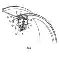
- a safety device 1according to the invention is mounted in its operating position on a cover device 2.
- the cover device 2consists of a comparatively strong polyurethane, so that the safety device 1 on a flange 3 is readily festschraubbar.
- the safety device 1is covered by a membrane 4 in the interior of the tube.
- the safety device 1is therefore accessible from the cover 2 having the end of the tube only by destroying the membrane 4 and removing the cover 2.
- a slide 6 of the safety device 1a structure-borne sound detection device is to be brought into contact with the pipe to be monitored.
- the slider 6 in the housingis movable so far that it rests against a pipe inside.
- a conductor loop 10is part of a cutting safeguard which serves to monitor the integrity of the membrane 4.
- the conductor formed by the conductor loop 10is interrupted, which leads to the output of an alarm signal.
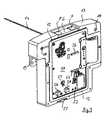
- the safety device 1is shown in more detail. Shown is a multi-sectional view of the safety device 1, wherein the view, inter alia, by removing the still in the Fig. 1 apparent housing cover 7 and a section in the direction R2 is formed parallel to the longitudinal center axis of the cover.
- the slider 6is shown with two magnets 7 in a guide 8 to.
- the slider 6is formed in the manner of a double Ts and with respect to a maximum stroke out of the housing of the safety device 1 through two Flanges 9 limited.
- An accumulator 11is used to power the safety device 1, while a seal 12 forms a sealing plane between the illustrated lower housing half 13 and in the Fig. 1 visible upper housing half 15 is arranged.
- the safety device 1is shown in an inactive position secured by a pin 16 connected to a chain 14.
- the safety devicecan be unlocked and turned on.
- the slider 6is due to its release from the blockage position according to Fig. 2 spring force assisted pressed in the direction of any pipe inner side, at the same time the magnets 7 supportive. Subsequently, the pin 16 can not be reintroduced into the securing position, since the slider 6 is in a situation in which safety device is inserted into a pipe, not accessible from the outside and can be switched off only when the cap and pushing the slider 6.
- a board 17 with a series of electronic components for the controlcovers the guide 8 for the slider 6.
- the seal 12is used to seal the individual assemblies on the board 17.
- Recesses 18 on the one handprovide a mounting option for attachment to a cover, on the other hand by a screw connection to the on the in Fig. 1 produced visible membrane 4 conductor loop 10.
- a contact plate 19can also serve to contact the conductor loop 10.
- the safety device when inserted into a tube with a pipe identification number and a tube storage spacecan be customized in a simple manner.
- bar code readerswhich can read the bar codes usually applied to tubes and correspondingly can describe an RFID chip can be used.
- the RFID chip 21is connected to an assembly 22 which provides a communication interface for communication with an associated monitoring system.
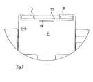
- a first reed switch 23is further arranged in the Fig. 3 is arranged at a height with a arranged in the slider 6 magnet 24 (cf. Fig. 4 ).
- Another reed switch 26is accessible via an extension of the slider 6 and represents a displacement assurance.
- the safety device 1has in its operating position on an education, in which the magnet 24 between the two reed switches 23, 26 is arranged.
- the magnet 24 of the slider 6comes into the area of the switch 26 and an alarm signal is output, since this position can be reached when removing from any pipe. This takes place, for example, when the cover is removed from the tube and the slider 6 is no longer applied to the pipe inner wall.
- the slider 6is arranged in its guide 8 movable in the direction R.
- Two force accumulators 29cause a bias of the slider 6 in the in Fig. 4 shown securing position in which the locking pin 16 is disposed in a recess 31 of the slider 6.
- a metal strip 32serves to connect the conductor loop 10 to the board 17.
- the magnet 24leaves the reed contact 23, whereupon the entire security device is armed. Since the slide hereby from its in Fig. 4 shown position in the Fig. 5 shown operating position, the recess 31 is no longer at a level with the recess 32 of the housing 13 still indicated in Fig. The locking pin is thus no longer inserted into the device and the safety device can not be turned off thereby.
- the slideIn the in Fig. 5 shown position, the slide is extended to the level of the pipe inner wall 33 shown in dashed lines. In this position, the magnets 7, which are poured into the slider and partially look out of this, are arranged on the tube inner wall side. For this purpose, the magnets 7 have a slightly rounded surface 34, which improves the system.
- the slider 6can be pushed back into the housing, whereupon the locking pin 16 can be inserted into the openings 31 and 32, so that the safety device is turned off. However, an alarm signal has already been issued at this time.
- the safety deviceis then equipped for maintenance with a new energy storage device 11 and can be used again.
- the magnets 7are coupled via a preferably ferromagnetic oscillating body 37.
- This couplingcauses on the one hand an improved magnetic support of the slider 6 on the tube inner wall and thus an improved recording of structure-borne noise.
- a structure-borne sound sensor 38which comprises a piezoelectric element in this embodiment, is arranged on the oscillating body 37.
- the slider 6is thus on the one hand part of the displacement assurance, part of the structure-borne noise detection device and also serves to turn on and off the fuse, which are realized in a component a variety of functions.
- the recorded signalis forwarded to an evaluation unit on the board 17 via an electrical connection, not shown.
- the detected structure-borne soundis evaluated, for example, filtered, and also triggered an alarm signal when certain criteria are met.
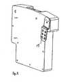
- a rear side of the safety deviceis shown, in which again the arrangement of the sheet 19 for contact with the conductor loop 10 can be seen.
- a safety devicewhich can well monitor with a plurality of complementary functions covering device or a pipe for pipes for pipeline construction.
Landscapes
- Engineering & Computer Science (AREA)
- Mechanical Engineering (AREA)
- General Engineering & Computer Science (AREA)
- Physics & Mathematics (AREA)
- Acoustics & Sound (AREA)
- Protection Of Pipes Against Damage, Friction, And Corrosion (AREA)
- Emergency Alarm Devices (AREA)
- Arrangements For Transmission Of Measured Signals (AREA)
- Casings For Electric Apparatus (AREA)
- Burglar Alarm Systems (AREA)
- Rigid Pipes And Flexible Pipes (AREA)
- Alarm Systems (AREA)
Description
Translated fromGermanDie vorliegende Erfindung betrifft eine Sicherheitsvorrichtung für eine Abdeckvorrichtung eines Rohres und/oder für ein Rohr, welches mit einer Reihe weiterer Rohre in vorzugsweise aneinander geschweißter Form zur Herstellung von Pipelines verwendbar ist, wobei die Abdeckvorrichtung eine eine Innenwand des Rohres abdeckende Hülse umfasst und die Sicherheitsvorrichtung zur Erzeugung eines Alarmsignals ausgebildet ist. Des Weiteren betrifft die Erfindung ein System zur Überwachung von Rohren.The present invention relates to a safety device for a covering device of a pipe and / or pipe, which is usable with a number of other pipes in preferably welded together form for the production of pipelines, wherein the covering comprises a sleeve covering an inner wall of the tube and the safety device is designed to generate an alarm signal. Furthermore, the invention relates to a system for monitoring pipes.
Rohre, die für den Pipelinebau verwendet werden, müssen höchsten Qualitätsanprüchen genügen. Die durch die Pipelines zu transportierenden Medien wie beispielsweise Öl können bei unsachgemäßem Zusammenbau große Schäden an der Umwelt verursachen. Darüber hinaus führen solche Schäden zu hohen finanziellen Belastungen der die Pipeline betreibenden Unternehmen. Vor dem Einbau in eine bestehende Pipeline bzw. vor dem Zusammenbau mehrerer Rohre zu einer Pipeline müssen gerade die Kanten und Schweißbereiche der Rohre besonders gut geschützt werden. Hierfür sind Abdeckvorrichtungen verwendbar, die insbesondere auch Teile der in den Enden des Rohres befindlichen Innenwand mittels einer Hülse od.dgl. abdichten. Um Schäden aufgrund von unsachgemäßem Gebrauch und damit einhergehenden Beeinträchtigungen der Integrität der Rohre sowie Manipulationen an den Rohren zu vermeiden, sollte der Transport und die Lagerung der Rohre bis zum Zusammenbau überwacht werden.Pipes used for pipeline construction must meet the highest quality standards. The media to be transported through the pipelines, such as oil, can cause serious damage to the environment if improperly assembled. In addition, such damage leads to high financial burdens on the companies operating the pipeline. Prior to installation in an existing pipeline or before assembling several pipes to form a pipeline, the edges and weld areas of the pipes must be particularly well protected. For this purpose, covering devices are used, in particular also parts of the inner wall located in the ends of the tube by means of a sleeve or the like. caulk. In order to prevent damage due to improper use and consequent damage to the integrity of the pipes, as well as manipulation of the pipes, the transport and storage of the pipes should be monitored until assembly.
Eine aus dem Stand der Technik bekannte Verschlussvorrichtung für Rohrleitungen ist beispielsweise der
Es ist daher Aufgabe der vorliegenden Erfindung, eine Sicherheitsvorrichtung zu schaffen, die zur Erzeugung eines Alarmsignals ausgebildet ist, und die sowohl für die Abdeckvorrichtung und/oder für ein Rohr verwendbar ist. Darüber hinaus ist es Aufgabe der vorliegenden Erfindung, ein System zur Überwachung von für den Pipelinebau vorgesehenen Rohren zu schaffen.It is therefore an object of the present invention to provide a safety device which is designed to generate an alarm signal, and which can be used both for the cover device and / or for a pipe. Moreover, it is an object of the present invention to provide a system for monitoring pipes intended for pipeline construction.
Die Aufgabe wird gelöst durch einen Gegenstand gemäß Anspruch 1 sowie durch einen Gegenstand gemäß Anspruch 27. Vorteilhafte Weiterbildungen der Gegenstände sind den jeweils auf die Ansprüche 1 und 27 rückbezogenen Unteransprüchen sowie der nachfolgenden Beschreibung zu entnehmen.The object is achieved by an article according to
Erfindungsgemäß umfasst die Sicherheitsvorrichtung eine ein Körperschallsensor umfassende Körperschalldetektionsvorrichtung zur Detektierung von Manipulationen am Rohr. Manipulationen am Rohr gehen beispielsweise einher mit Klopf- oder Schweißgeräuschen und damit einher mit einem charakterischen Körperschall. Auch ein unbeabsichtigtes Fallenlassen des Rohres während seines Transports erzeugt im Rohr Körperschall. Verschiedener Körperschall lässt sich somit charakteristischen Ursachen zuordnen. Eine Sicherheitsvorrichtung, die eine Körperschalldetektionsvorrichtung mit einem Körperschallsensor aufweist, kann den Körperschall, der im Rohr auftritt, aufnehmen und - vorzugsweise bei einer elektronisch unterstützten Auswertung - die Ausgabe eines Alarmsignals veranlassen. Hierfür kann die Körperschalldetektionsvorrichtung geeignete Mittel zur Auswertung des vom Sensor aufgenommenen Signals aufweisen.According to the invention, the safety device comprises a structure-borne noise sensor comprising a structure-borne sound detection device for detecting manipulations on the pipe. Manipulations on the pipe, for example, are accompanied by knocking or welding noises and, as a result, a characteristic structure-borne noise. Even accidental dropping of the tube during its transport generates structure-borne noise in the pipe. Different structure-borne noise can thus be assigned to characteristic causes. A safety device having a structure-borne sound detection device with a structure-borne sound sensor can record the structure-borne noise that occurs in the pipe and - preferably in an electronically assisted evaluation - cause the issuing of an alarm signal. For this purpose, the structure-borne noise detection device may comprise suitable means for evaluating the signal received by the sensor.
Um eine gute Aufnahme des Körperschalls des Rohres zu ermöglichen ist die Körperschalldetektionsvorrichtung vorteilhafterweise auf die Rundung der Rohrinnenseite angepasst.In order to enable a good absorption of structure-borne noise of the pipe, the structure-borne sound detection device is advantageously adapted to the rounding of the inside of the pipe.
In einer vorteilhaften Ausgestaltung der Erfindung ist die Körperschalldetektionsvorrichtung mit einem Piezo-Element versehen, welches der Aufnahme des Körperschalls und dessen Umwandlung in elektrische Impulse dient. Das Piezo-Element ist somit insbesondere Teil des Körperschallsensors.In an advantageous embodiment of the invention, the structure-borne sound detection device is provided with a piezoelectric element which serves to record the structure-borne noise and its conversion into electrical impulses. The piezo element is thus in particular part of the structure-borne sound sensor.
Das Piezo-Element kann beispielsweise nach Art einer Stimmgabel teilweise frei schwingend ausgebildet sein. Bevorzugt ist jedoch eine Ausbildung, in der das Piezo-Element oder ein anderer Körperschallsensor an einem Schwingkörper angeordnet ist, der insbesondere von seiner Eigenfrequenz her auf den Frequenzbereich des zu detektierenden Körperschalls abgestimmt ist. Der Schwingkörper kann beispielsweise ein Metallstreifen sein, dessen Form und Abmessungen (z.B. Länge, Breite, Höhe) auf den aufzunehmenden Körperschall abgestimmt ist. Der Schwingkörper der Körperschalldetektionsvorrichtung bzw. der Sicherheitsvorrichtung ist hierbei mittelbar oder unmittelbar in Anlage mit der Innenseite der Rohrwand zu bringen, um deren Körperschall aufzunehmen und an das Piezo-Element weiterzuleiten bzw. abzugeben.The piezoelectric element may be partially freely swinging, for example in the manner of a tuning fork. However, an embodiment in which the piezoelectric element or another structure-borne noise sensor is arranged on a vibrating body, which is tuned in particular by its natural frequency to the frequency range of the structure-borne sound to be detected, is preferred. The oscillating body can be, for example, a metal strip whose shape and dimensions (for example, length, width, height) are matched to the structure-borne sound to be recorded. The vibrating body of the structure-borne noise detection device or the safety device here is to bring indirectly or directly into contact with the inside of the tube wall to record the structure-borne sound and forward to the piezoelectric element or deliver.
Bei den zu detektierenden Geräuschen, die sich im Rohr fortsetzen, handelt es sich in der Regel nicht um eine einzelne Frequenz sondern um eine Mehrzahl von Frequenzen bzw. ein Frequenzband, welches beispielsweise durch Bohren oder Klopfen am Rohr erzeugt wird. Beispielsweise handelt es sich hierbei um ein Frequenzbereich zwischen 10 und 20 kHz, in dem der Schwingkörper ebenfalls eine Eigenfrequenz aufweist.The sounds to be detected, which continue in the tube, are generally not a single frequency but a plurality of frequencies or a frequency band which is generated, for example, by drilling or knocking on the tube. For example, this is a frequency range between 10 and 20 kHz, in which the vibrating body also has a natural frequency.
Bei Verwendung eines Schwingkörpers mit einer abgestimmten Figenfrequenz ist insbesondere von Vorteil, dass der Körperschallsensor bzw. das Piezo-Element nicht in unmittelbarer Anlage an der Rohrinnenwand liegen muss. Es kann entsprechend geschützt angeordnet werden. Aufgrund der Abstimmung des Schwingkörpers ist dennoch eine hohe Sensitivität der Körperschalldetektionsvorrichtung gewährleistet. Das Piezo-Element und der Schwingkörper sind des Weiteren, sofern sie beispielsweise in einem Material eingegossen sind, an die Dämpfung durch dieses Material angepasst.When using a vibrating body with a tuned Figenfrequenz is particularly advantageous that the structure-borne sound sensor or the piezoelectric element must not be in direct contact with the inner wall of the pipe. It can be arranged appropriately protected. Due to the tuning of the vibrating body nevertheless a high sensitivity of the structure-borne noise detection device is ensured. Furthermore, the piezoelectric element and the oscillating body, if they are cast in a material for example, are adapted to the damping by this material.
Vorzugsweise ist der Schwingkörper selbst unter Verwendung zumindest eines Magneten an der Innenwand des zu überwachenden Rohres anbringbar. D.h. die Körperschalldetektionsvorrichtung umfasst zumindest einen Magneten zur Halterung wenigstens eines Teils der Körperschalldetektionsvorrichtung an dem zu überwachenden Rohr. Das Rohr ist nicht Teil der Erfindung.Preferably, the oscillating body itself can be attached using at least one magnet to the inner wall of the pipe to be monitored. That the structure-borne sound detection device comprises at least one magnet for holding at least a part of the structure-borne noise detection device on the pipe to be monitored. The tube is not part of the invention.
Bei der Verwendung zweier Magnete, die beabstandet voneinander angeordnet sind, kann durch Verbindung dieser beiden Magnete mittels einer den Schwingkörper ausbildenden Brücke die Magnetkopplungskraft verstärkt werden, um eine noch bessere Anbringung an einer Rohrinnenwand zu ermöglichen. Die in Richtung der Innenseite eines etwaigen Rohres hin auszurichtenden Oberflächen des Magneten sind hierbei ebenfalls wieder der Wandung anpassbar, d.h. mit einer entsprechenden geringfügigen Rundung versehen oder sogar einstellbar.By using two magnets spaced apart from each other, by coupling these two magnets by means of a bridge forming the vibrating body, the magnetic coupling force can be enhanced to allow an even better attachment to a pipe inner wall. The surfaces of the magnet which are to be aligned in the direction of the inside of a possible tube are likewise adaptable to the wall, i. provided with a corresponding slight rounding or even adjustable.
Alternativ oder ergänzend kann die Körperschalldetektionsvorrichtung zur mechanischen Halterung wenigstens eines Teils der Körperschalldetektionsvorrichtung an dem Rohr ausgebildet sein. Hierfür können ein oder mehrere Kraftspeicher wie beispielsweise ein oder mehrere Federn vorgesehen werden, die wenigstens einen Teil der Körperschalldetektionsvorrichtung, insbesondere den Magnet, Schwingkörper und Piezo-Element aufweisenden Teil gegen die Innenseite einer Rohrwand drücken können. Der Rest der Sicherheitsvorrichtung ist entsprechend fixierbar zu gestalten, dergestalt, dass sich der Kraftspeicher abstützen kann. Dies kann beispielsweise durch die Anbringungsmöglichkeit, die Sicherheitsvorrichtung an einer etwaigen Abdeckvorrichtung anzuschrauben, gegeben sein.Alternatively or additionally, the structure-borne noise detection device may be designed to mechanically support at least part of the structure-borne sound detection device on the tube. For this purpose, one or more energy storage such as one or more springs are provided which press at least a portion of the structure-borne noise detection device, in particular the magnet, vibrating body and piezoelectric element having part against the inside of a pipe wall can. The rest of the safety device is designed to be fixed accordingly, such that the energy storage can be supported. This can for example be given by the possibility of attaching the safety device to any cover device.
Vorzugsweise weist die Sicherheitsvorrichtung einen beweglichen Teil auf, insbesondere einen Schieber, der die Magnete, eine einen Schwingkörper ausbildende Brücke und das Piezo-Element umfasst, und der entsprechend in Anlage mit der Rohrwandinnenseite aufgrund einer Kombination von Magnet- und/oder mechanischer, insbesondere Feder-Kraft bringbar ist.Preferably, the safety device has a movable part, in particular a slide, which comprises the magnets, a bridge forming a vibrating body and the piezo element, and which accordingly in abutment with the pipe wall inside due to a combination of magnetic and / or mechanical, in particular spring Force can be brought.
Vorzugsweise ist die Sicherheitsvorrichtung zur Detektierung von Manipulationen an einer Abdeckvorrichtung, an der die Sicherheitsvorrichtung im Einzelfall angeordnet sein kann, ausgebildet. Hiernach ist einerseits eine Überwachung des Rohres selbst gegen Beeinträchtigungen von dessen Integrität sowie eine Überwachung der die Rohre üblicherweise vor deren Verwendung an ihren Enden abdeckenden Abdeckvorrichtung geschaffen.Preferably, the security device is designed to detect tampering on a cover device on which the security device can be arranged in an individual case. Thereafter, on the one hand monitoring of the tube itself against adverse effects on its integrity and monitoring of the pipes usually before their use covering at their ends covering created.
Vorteilhafterweise kann die Sicherheitsvorrichtung an einer Innenhülse einer Abdeckvorrichtung anschraubbar ausgebildet sein. Um insbesondere mechanische Beschädigungen oder andere Manipulationen an der Abdeckvorrichtung detektieren zu können, kann die Sicherheitsvorrichtung eine insbesondere als Schnittsicherung ausgebildete Sicherung zur Detektierung mechanischer Beschädigungen der Abdeckvorrichtung aufweisen. Hierbei kann es sich besonders vorteilhaft eine Leiterschleife handeln, welche beispielsweise an einer Membran der Abdeckvorrichtung anbringbar ist. Eine solche strom- bzw. spannungsbeaufschlagbare Leiterschleife kann den lichten Innenquerschnitt eines Rohres zumindest teilweise abdecken und bei einem Durchtrennen der Leiterelemente ein Alarmsignal auslösen. Vorteilhaft ist auch ein unter Spannung stehendes Leiternetz, welches auf die Membran aufgebracht oder als Membran ausgebildet ist, wobei die Sicherheitsvorrichtung mit Beschädigungen einhergehenden Spannungsänderungen detektieren kann.Advantageously, the safety device can be screwed onto an inner sleeve of a cover device. In order to be able to detect in particular mechanical damage or other manipulations on the covering device, the safety device can have a securing device designed in particular as a sectional securing device for detecting mechanical damage of the covering device. In this case, it can be particularly advantageous to use a conductor loop, which can be attached, for example, to a membrane of the covering device. Such current or Spannungsbeaufschlagbare conductor loop can cover the clear inner cross section of a pipe at least partially and trigger an alarm signal when the conductor elements are severed. Also advantageous is a live conductor network, which is applied to the membrane or formed as a membrane, wherein the safety device can detect voltage changes associated with damage.
In einer weiteren vorteilhaften Weiterbildung der Erfindung umfasst die Sicherheitsvorrichtung eine Verlagerungssicherung, die zur Detektierung einer Änderung der Position der Sicherheitsvorrichtung insbesondere relativ zu einem etwaigen vorhandenen und zu überwachenden Rohr ausgebildet ist. Eine solche Verlagerungssicherung kann beispielsweise in Form einer Beschleunigungssensors ausgebildet sein, der eine Bewegung der Sicherheitsvorrichtung detektieren kann. Besonders vorteilhaft ist jedoch eine Ausbildung, in der die Vertagerungssicherung einen kraftbeaufschlagten Schieber umfasst und die Sicherheitsvorrichtung weiterhin zur Ausgabe eines Alarmsignals bei Verlagerung des Schiebers vorzugsweise in dessen Endlage ausgebildet ist. Der kraftbeaufschlagte Schieber kann sich während der Betriebstellung der Sicherheitsvorrichtung, sofern diese in einem Rohr angeordnet ist, an der Rohrinnenwand abstützen. Sofern die Sicherheitsvorrichtung von dem Rohr entfernt wird, wird der Schieber kraftbeaufschlagt nach außen gedrückt. Die hiermit einhergehende Verlagerung des Schiebers relativ zu dem Rest der Sicherheitsvorrichtung führt zur Erzeugung eines Alarmsignals.In a further advantageous embodiment of the invention, the safety device comprises a displacement assurance, which is designed to detect a change in the position of the safety device, in particular relative to any existing existing and monitored pipe. Such a displacement assurance can be configured for example in the form of an acceleration sensor, which can detect a movement of the safety device. Particularly advantageous, however, is an embodiment in which the restraint safety device comprises a force-loaded slide and the safety device is furthermore designed to emit an alarm signal upon displacement of the slide, preferably in its end position. The force-loaded slide can, during the operating position of the safety device, if it is arranged in a tube, be supported on the tube inner wall. If the safety device is removed from the pipe, the slider is forced by force to the outside. The concomitant displacement of the slider relative to the remainder of the safety device results in the generation of an alarm signal.
Vorzugsweise weist die Sicherheitsvorrichtung einen in einer Führung bewegbaren Schieber auf, der eine Mehrzahl von Funktionen übernehmen kann, wobei an wenigstens einer Position des Schiebers entlang der Führung ein Signal erzeugt werden kann. Hierfür können beispielsweise mechanische Schalter oder magnetische Schalter wie von einem im Schieber angeordneten Magneten betätigbare Reed-Schalter vorgesehen werden.Preferably, the safety device has a slide which can be moved in a guide and which can assume a plurality of functions, wherein a signal can be generated at at least one position of the slide along the guide. For this purpose, mechanical switches or magnetic switches, for example, can be provided, such as a reed switch which can be actuated by a magnet arranged in the slide.
Besonders bevorzugt ist der Schieber gleichzeitig auch Teil der Körperschalldetektionsvorrichtung. Beispielsweise kann am nach außen hin sichtbaren Ende des Schiebers ein Magnet zur Koppelung der Außenseite des Schiebers mit der Rohrinnenwand vorhanden sein. Dies bewirkt gleichzeitig, dass der Schieber zusätzlich zu einer etwaigen Kraftbeaufschlagung ggf. auch alternativ zu einer solchen an der Wand eines zu überwachenden Rohres verbleibt und insofern der Schieber bei einer beabsichtigten Manipulation eine Lageveränderung erfährt relativ zum Rest der Sicherheitsvorrichtung. Die führt wieder zu der Ausgabe des Alarmsignals.At the same time, the slider is also preferably part of the structure-borne noise detection device. For example, may be present on the outwardly visible end of the slide, a magnet for coupling the outside of the slide with the pipe inner wall. This simultaneously causes the slide, in addition to any application of force, also, if appropriate, also to remain on the wall of a pipe to be monitored, and insofar the slide undergoes a change in position during an intended manipulation relative to the rest of the safety device. This leads again to the output of the alarm signal.
In einer weiteren vorteilhaften Ausgestaltung der Sicherheitsvorrichtung weist dieser einen Temperatursensor auf, der bei Erreichen kritischer Temperaturen einen Alarm initiiert. Beispielsweise wird bei Anordnung der Sicherheitsvorrichtung an einer Abdeckvorrichtung oder bei Integration der Sicherheitsvorrichtung in eine Abdeckvorrichtung dann ein Alarm ausgegeben, wenn die Abdeckvorrichtung abbrennt oder abgebrannt wird.In a further advantageous embodiment of the safety device, the latter has a temperature sensor which initiates an alarm when critical temperatures are reached. For example, when the safety device is mounted on a cover device or when the safety device is integrated with a cover device, an alarm is issued when the cover device is burned or burned down.
Vorzugsweise ist der Temperatursensor an einem bezüglich des Körperschallsensors entgegengesetzten Ende der Sicherheitsvorrichtung angeordnet. Hierdurch wird der Temperatursensor nicht von den zum teilweise bis auf 50° ansteigenden Temperaturen einer etwaigen Rohrwand beeinflusst.The temperature sensor is preferably arranged on an end of the safety device which is opposite the structure-borne sound sensor. As a result, the temperature sensor is not influenced by the temperatures rising up to 50 ° in some case of a pipe wall.
Vorzugsweise ist der Temperatursensor über eine Klemmverbindung befestigt, so dass bei der Herstellung der Sicherheitsvorrichtung der Temperatursensor nicht durch etwaige Lötvorgänge bereits beschädigt wird.Preferably, the temperature sensor is attached via a clamping connection, so that during the manufacture of the safety device, the temperature sensor is not already damaged by any soldering operations.
Zusätzlich zu den bereits beschrieben sicherheitsrelevanten Funktionen kann die Sicherheitsvorrichtung Sensoren bzw. Vorrichtungen, die auf andere Umgebungsvariablen als Schall oder Temperatur reagieren, aufweisen. Beispielsweise ist die Überwachung eines Rohres weiterhin verbessert, wenn die Sicherheitsvorrichtung wenigstens einen Feuchtigkeits- und/oder einen Gasfühler aufweist. Eine erfindungsgemäße Sicherheitsvorrichtung kann weiterhin vorteilhafterweise einen Sensor zur Detektierung von weiteren korrosionsbeeinflussenden Parametern insbesondere in der Luft innerhalb des Rohres aufweisen. Hierbei kann es sich z.B. um einen salzgehalts-Sensor handeln.In addition to the safety-related functions already described, the safety device may include sensors or devices that respond to environmental variables other than sound or temperature. For example, the monitoring of a pipe is further improved if the safety device has at least one moisture sensor and / or one gas sensor. A safety device according to the invention can furthermore advantageously have a sensor for detecting further parameters influencing corrosion, in particular in the air within the tube. This may be e.g. to trade a salt content sensor.
Die Sicherheitsvorrichtung ist zur Ausgabe eines Alarmsignals ausgebildet, wobei dieses Alarmsignal beispielsweise ein von der Sicherheitsvorrichtung über einen Lautsprecher abgegebenen Ton oder ein Leuchtsignal einer Anzeige ist. Vorzugsweise ist die Sicherheitsvorrichtung jedoch mit einem Transmitter zur Ausgabe eines Funksignals oder anderer drahtlos übermittelbarer Signale ausgebildet. Hierfür ist die Sicherheitsvorrichtung mit einer elektronischen Steuerung zur insbesondere die Ausgabe eines Alarmsignals bewirkenden Kommunikation versehen. Die Kommunikationsmittel sind insbesondere für eine bidirektionale Kommunikation geeignet. Die Sicherheitsvorrichtung ist somit in der Lage, auch auf externe Anfragen hin einen Statusbericht od. dgl. gezielte Informationen abgeben zu können.The safety device is designed to output an alarm signal, this alarm signal being, for example, a sound emitted by the safety device via a loudspeaker or a flashing signal of a display. Preferably, however, the safety device is formed with a transmitter for outputting a radio signal or other wirelessly communicable signals. For this purpose, the safety device is provided with an electronic control for in particular the output of an alarm signal causing communication. The communication means are particularly suitable for bidirectional communication. The security device is thus able to issue a status report or the like for specific requests.
Besonders vorteilhaft ist eine solche Steuerung, wenn sie mit einem RFID-Bauelement verbunden ist, welches einen mit bekannten Mitteln beschreibbaren Speicher aufweist, in dem beispielsweise Lagerplatz-ID oder Rohr-ID gespeichert werden können. Insofern ist man mittels der erfindungsgemäßen Sicherheitsvorrichtung in der Lage, ein Rohr zu identifizieren und dieses auch über die elektronische Steuerung zu kommunizieren.Such a controller is particularly advantageous if it is connected to an RFID component which has a memory which can be written on by known means and in which, for example, storage bin ID or pipe ID can be stored. In this respect, it is possible by means of the safety device according to the invention to identify a pipe and to communicate this also via the electronic control.
Vorzugsweise ist die Sicherheitsvorrichtung dergestalt ausgebildet, dass sie in regelmäßigen Abständen ein Statussignal bezüglich einer zugehörigen Energiequelle abgibt. Eine solche Energiequelle ist insbesondere Teil einer autonomen Energieversorgung beispielsweise auf Akkumulatoren-, Solar- oder Windenergiebasis.Preferably, the safety device is designed such that it emits a status signal with respect to an associated energy source at regular intervals. Such an energy source is in particular part of an autonomous energy supply, for example on an accumulator, solar or wind energy basis.
Um die Sicherheitsvorrichtung möglichst sicher vor Umgebungseinflüssen zu gestalten, weist sie ein zweigeteiltes äußeres Gehäuse auf, welches in einer Betriebsstellung einen abgedichteten Hohlraum zur Aufnahme elektronischer Komponenten ausbildet. Dieses zweigeteilte äußere Gehäuse ist insbesondere aus gegossenem oder gespritztem Polyurethan gebildet und als solches entsprechend massiv. Aufgrund der zugehörigen Sensoren muss das Gehäuse nicht aus schwer zerstörbaren Materialien gebildet werden, da die Sensoren vorher etwaige Manipulationsversuche detektieren würden und entsprechend Alarm ausgeben würden.To make the safety device as safe as possible from environmental influences, it has a two-part outer housing, which forms a sealed cavity for receiving electronic components in an operating position. This two-part outer housing is formed in particular of cast or injected polyurethane and as such correspondingly solid. Due to the associated sensors, the housing does not have to be formed from materials which are difficult to destroy, since the sensors would previously detect any manipulation attempts and would accordingly output an alarm.
Die Aufgabe wird weiterhin gelöst durch ein System zur Überwachung von Rohren, welches eine Mehrzahl von vorbeschriebenen Sicherheitsvorrichtungen aufweist und des Weiteren eine Empfangsstation zum Empfang der vorzugsweise mittels eines Repeaters weiterleitbaren Signalen der Sicherheitsvorrichtung. Des Weiteren weist dass System eine elektronischen Datenverarbeitung, die zur Auswertung der Signale und zur Ausgabe eines Alarmsignals ausgebildet ist, auf.The object is further achieved by a system for monitoring pipes, which has a plurality of security devices as described above, and further comprises a receiving station for receiving the preferably forwarded by means of a repeater signals of the security device. Furthermore, the system has electronic data processing which is designed to evaluate the signals and to output an alarm signal.
Mit einem solchen System können neben Statusabfragen bezüglich Rohr-ID und -Lagerplatz beispielsweise auch Temperaturen an Abdeckvorrichtungen, an denen Sicherheitsvorrichtungen angebracht sind bzw. die Menge der überwachten Rohre regelmäßig und unkompliziert abgefragt werden. Von der Empfangsstation können Signale der jeweiligen Sicherheitsvorrichtungen aufgenommen werden, woraufhin die Signale in der Datenverarbeitung ausgewertet werden.With such a system, in addition to status queries regarding pipe ID and storage space, for example, temperatures on covering devices to which security devices are attached or the quantity of pipes monitored can be queried regularly and simply. From the receiving station can Received signals of the respective security devices, whereupon the signals are evaluated in the data processing.
Vorteilhafterweise umfasst das System darüber hinaus eine erste Kontrollstation, die die elektronische Datenverarbeitung wenigstens teilweise umfasst, d.h. in der erste Auswertungen vorgenommen werden können, sowie eine zweite Kontrollstation, die lokal beabstandet und über vorzugsweise als Internetverbindung ausgebildete Kommunikationsmittels mit der ersten Kontrollstation verbunden ist. Eine einzelner mit einer Vielzahl von Rohren und entsprechend zugehörigen Sicherheitsvorrichtungen ausgestatteter Lagerplatz kann somit einerseits teilweise lokal verwaltet werden, darüber hinaus jedoch auch von einem völlig verschiedenen Ort, beispielsweise auf einem anderen Kontinent, gemanagt werden. Im Falle eines Alarmsignals können so Ressourcen gezielt verteilt und mögliche Problemfälle schnell behoben werden.Advantageously, the system further comprises a first control station which at least partially comprises electronic data processing, i. in the first evaluations can be made, and a second control station, which is locally spaced and connected via preferably designed as an Internet connection communication means with the first control station. Thus, a single storage bin equipped with a plurality of tubes and corresponding associated safety devices can be partly locally managed but, moreover, managed from a completely different location, for example on another continent. In the case of an alarm signal, resources can be distributed in a targeted manner and possible problems can be quickly remedied.
Vorzugsweise ist das System dergestalt ausgebildet, dass es Sicherungsroutinen umfasst, d.h., dass ein Alarmsignal solange weiter ausgesendet wird, bis von einer hierzu autorisierten Stelle beispielsweise in der ersten oder in der zweiten Kontrollstation ein entsprechendes Bestätigungssignal zur Sicherheitsvorrichtung zurückversand wird.Preferably, the system is arranged to include backup routines, that is to say that an alarm signal continues to be transmitted until a corresponding acknowledgment signal is sent back to the security device from a location authorized for this, for example in the first or in the second control station.
Das System kann in einer weiteren Ausbildung mit einer Sicherung versehen sein, bei der die elektronische Datenverarbeitung zur Überprüfung des wenigstens einen Repeaters ausgebildet ist. Etwaige Ausfälle von einzelnen Repeatern werden somit vor Eintreten eines Alarmfalls erkannt und die Ausfallsicherheit des System wird erhöht.The system may be provided in a further embodiment with a backup in which the electronic data processing is designed to check the at least one repeater. Any failures of individual repeaters are thus detected before the occurrence of an alarm case and the reliability of the system is increased.
Weitere Vorteile und Einzelheiten der Erfindung lassen sich der nachfolgenden Figurenbeschreibung entnehmen. In den Abbildungen zeigt schematisch:
- Fig. 1
- eine perspektivische Darstellung eines erfindungsgemäßen Gegenstands in einer Position an einer Abdeckvorrichtung,
- Fig. 2
- den
Gegenstand gemäß Figur 1 in einer mehrfach geschnittenen Ansicht, - Fig. 3
- eine erfindungsgemäße Sicherheitsvorrichtung mit geöffnetem Gehäuse,
- Fig. 4
- den Gegenstand nach
Fig. 3 in einer Draufsicht ohne Platine, - Fig. 5
- den Gegenstand nach
Fig. 4 in einer weiteren Ansicht, - Fig. 5
- den Gegenstand nach
Fig. 4 in einer weiteren Ansicht, - Fig. 7
- eine Detailansicht eines erfindungsgemäßen Gegenstands,
- Fig. 8
- den Gegenstand nach
Fig. 3 in einer rückwärtigen Ansicht.
- Fig. 1
- a perspective view of an article according to the invention in a position on a cover,
- Fig. 2
- the object according to
FIG. 1 in a multi-section view, - Fig. 3
- a safety device according to the invention with opened housing,
- Fig. 4
- the object after
Fig. 3 in a plan view without board, - Fig. 5
- the object after
Fig. 4 in another view, - Fig. 5
- the object after
Fig. 4 in another view, - Fig. 7
- a detailed view of an article according to the invention,
- Fig. 8
- the object after
Fig. 3 in a rear view.
Gleich oder ähnlich wirkende Teile sind - sofern dienlich - mit identischen Bezugsziffern versehen. Einzelne technische Merkmale der nachfolgend beschriebenen Ausführungsbeispiele können auch mit den Merkmalen der vorbeschriebenen Ausführungsbeispiele zu erfindungsgemäßen Weiterbildungen führen.Equal or similar parts are - if appropriate - provided with identical reference numbers. Individual technical features of the exemplary embodiments described below can also lead to developments of the invention with the features of the above-described embodiments.
In der
In einer Situation, in der die Abdeckvorrichtung 2 mitsamt der Sicherheitsvorrichtung 1 zur Abdeckung eines Rohrendes in dieses eingebracht ist, befindet sich die Sicherheitsvorrichtung 1 von einer Membran 4 abgedeckt im Inneren des Rohres. Die Sicherheitsvorrichtung 1 ist somit von dem die Abdeckvorrichtung 2 aufweisenden Ende des Rohres nur durch Zerstören der Membran 4 bzw. Herausnehmen der Abdeckvorrichtung 2 zugänglich. Mittels eines Schiebers 6 der Sicherheitsvorrichtung 1 ist eine Körperschalldetektionsvorrichtung in Anlage mit dem zu überwachenden Rohr zu bringen. Hierfür ist der Schieber 6 in dem Gehäuse soweit bewegbar, dass er an einer Rohrinnenseite anliegt.In a situation in which the
Eine lediglich gestrichelt angedeutete Leiterschleife 10 ist Teil einer Schnittsicherung, die der Überwachung der Integrität der Membran 4 dient. Bei einem Zerschneiden der Membran 4 ist der durch die Leiterschleife 10 ausgebildete Leiter unterbrochen, was zur Ausgabe eines Alarmsignals führt.A
In der
In der Figur ist der Schieber 6 mit zwei Magneten 7 in einer Führung 8 zu dargestellt. Der Schieber 6 ist nach Art eines Doppel-Ts ausgebildet und bezüglich eines maximalen Hubes aus dem Gehäuse der Sicherheitsvorrichtung 1 heraus durch zwei Flansche 9 begrenzt. Ein Akkumulator 11 dient der Energieversorgung der Sicherheitsvorrichtung 1, während eine Dichtung 12 eine Dichtebene ausbildet, die zwischen der dargestellten unteren Gehäusehälfte 13 und der in der
In der in
In der Ansicht gemäß
Über einen RFID-Chip 21 kann die Sicherheitsvorrichtung bei Einbringen in ein Rohr mit einer Rohr-Identifikationsnummer und einem Rohr-Lagerplatz auf einfache Art und Weise individualisiert werden. Hierfür können beispielsweise Barcodeleser, die die üblicherweise auf Rohren aufgebrachten Strichcodes lesen und entsprechend einen RFID-Chip beschreiben können, verwendet werden.About an
Der RFID-Chip 21 ist mit einer Baugruppe 22 verbunden, die eine Kommunikationsschnittstelle zur Kommunikation mit einem zugehörigen Überwachungssystem bereitstellt.The
Auf der Platine 17 ist weiterhin ein erster Reed-Schalter 23 angeordnet, der in der
Ein weiterer Reed-Schalter 26 ist über ein Ausfahren des Schiebers 6 erreichbar und stellt eine Verlagerungssicherung dar. Die Sicherheitsvorrichtung 1 weist in ihrer Betriebsstellung eine Ausbildung auf, bei der der Magnet 24 zwischen den beiden Reed-Schaltern 23, 26 angeordnet ist. Bei Ausfahren des Schiebers 6 in seine Endlage gelangt der Magnet 24 des Schiebers 6 in den Bereich des Schalters 26 und ein Alarmsignal wird ausgegeben, da diese Position bei Entfernen von einem etwaigen Rohr erreichbar ist. Dies findet beispielsweise dann statt, wenn die Abdeckvorrichtung aus dem Rohr entfernt wird und der Schieber 6 nicht mehr an der Rohrinnenwand anliegt.Another
Auf der in
Der Schieber 6 ist in seiner Führung 8 beweglich in Richtung R angeordnet. Zwei Kraftspeicher 29 bewirken eine Vorspannung des Schiebers 6 in der in
Ein Metallstreifen 32 dient der Anbindung der Leiterschleife 10 an die Platine 17.A
Durch Entnahme des Sicherungsstiftes 16 verlässt der Magnet 24 den Reed-Kontakt 23, woraufhin die gesamte Sicherheitsvorrichtung scharf geschaltet wird. Da der Schieber hierbei aus seiner in
Bei Entnahme der Abdeckvorrichtung 2 zusammen mit der Sicherheitsvorrichtung 1 und entsprechendem Entfernen der Sicherheitsvorrichtung 1 von der Rohrinnenwand 33 fährt der Schieber aufgrund der Kraftspeicher 29 weiter heraus wobei der Magnet 24 über den Reed-Kontakt 26 ein Signal bewirkt, aufgrund dessen von der elektronischen Steuerung ein Alarm ausgegeben wird. In der in
Nach einer Entnahme der Sicherheitsvorrichtung 1 aus dem Rohr kann der Schieber 6 wieder in das Gehäuse hineingedrückt werden, woraufhin der Sicherungsstift 16 in die Öffnungen 31 und 32 eingeführt werden kann, sodass die Sicherheitsvorrichtung ausgeschaltet wird. Ein Alarmsignal ist zu diesem Zeitpunkt jedoch bereits ausgegeben worden. Die Sicherheitsvorrichtung ist dann zur Wartung mit einem neuen Energiespeicher 11 bestückbar und kann wieder verwendet werden.After removal of the
In dem Kopf des Schiebers 6 sind die Magneten 7 über einen vorzugsweise ferromagnetischen Schwingkörper 37 gekoppelt. Diese Kopplung bewirkt einerseits eine verbesserte magnetische Halterung des Schiebers 6 an der Rohrinnenwand und somit einer verbesserten Aufnahme des Körperschalls. Außerdem ist an dem Schwingkörper 37 ein Körperschallsensor 38, der in diesem Ausführungsbeispiel ein Piezoelement umfasst, angeordnet. Der Schieber 6 ist somit einerseits Teil der Verlagerungssicherung, Teil der Körperschalldetektionsvorrichtung und dient weiterhin dem Ein- und Ausschalten der Sicherung, wodurch in einem Bauteil eine Vielzahl von Funktionen realisiert werden.In the head of the
Von dem Körperschallsensor wird über eine nicht näher dargestellte elektrische Verbindung das aufgenommene Signal zu einer Auswerteeinheit auf der Platine 17 weitergeleitet. In dieser wird der detektierte Körperschall ausgewertet, beispielsweise gefiltert, und bei Eintreffen bestimmter Kriterien ebenfalls wieder ein Alarmsignal ausgelöst.Of the structure-borne sound sensor, the recorded signal is forwarded to an evaluation unit on the
In der
Insbesondere durch die Kombination einzelner vorbeschriebener Aspekte einer Sicherheitsvorrichtung wird eine Sicherheitsvorrichtung geschaffen, die mit einer Mehrzahl von sich ergänzenden Funktionen Abdeckvorrichtung bzw. ein Rohr für Rohre für den Pipelinebau gut überwachen kann.In particular, by the combination of individual aspects of a safety device described above, a safety device is provided, which can well monitor with a plurality of complementary functions covering device or a pipe for pipes for pipeline construction.
Claims (30)
- Security device for an arrangement (2) for covering a pipe and/or for a pipe which, together with a series of further pipes in welded-together form, can be used to produce pipelines, the covering arrangement (2) comprising a sleeve (5) which covers an inner wall of the pipe and the security device (1) being designed to generate an alarm signal, and the security device (1) having an arrangement for detecting solid-borne sound which comprises a sensor for solid-borne sound (38), for detecting interference with the pipe.
- Security device according to claim 1,characterised in that the arrangement for detecting solid-borne sound has a piezo-electric member.
- Security device according to either of the preceding claims,characterised in that the arrangement for detecting solid-borne sound comprises a body able to vibrate (37) which is tuned to the frequency range of the solid-borne sound to be detected, preferably from its resonant frequency.
- Security device according to one of the preceding claims,characterised in that the arrangement for detecting solid-borne sound comprises at least one magnet (7) for mounting at least a part (6) of the arrangement for detecting solid-borne sound on the pipe.
- Security device according to one of the preceding claims,characterised in that the arrangement for detecting solid-borne sound is designed to allow at least a part (6) of the arrangement for detecting solid-borne sound to be mounted mechanically on the pipe.
- Security device for an arrangement for covering a pipe, in particular according to one of the preceding claims,characterised in that the security device (1) is designed to detect interference with the covering arrangement (2).
- Security device according to one of the preceding claims,characterised by an analysing arrangement which analyses the received signal from the sensor for solid-borne sound.
- Security device according to one of the preceding claims,characterised in that the security device (1) is designed to rest against an inner sleeve (4) of the covering arrangement (2).
- Security device according to one of the preceding claims,characterised in that an anti-displacement safeguarding system is designed to detect a change in the position of the security device (1) relative to the pipe being monitored.
- Security device according to claim 9,characterised in that the anti-displacement safeguarding system comprises a slider (6) and, in the event of a displacement of the slider (6), the security device is designed to emit an alarm signal when the slider (6) is in its end position.
- Security device according to one of the preceding claims,characterised by a slider (6) able to move in a guide (8), a signal being able to be generated when the slider (6) is in at least one position along the guide (8).
- Security device according to claim 11,characterised in that force can be applied to the slider by means of a force-storing means (29).
- Security device according to one of the preceding claims,characterised by a temperature sensor (27).
- Security device according to one of the preceding claims,characterised in that the temperature sensor (27) is arranged at an opposite end of the security device from the sensor for solid-borne sound (38).
- Security device according to claim 14,characterised in that the temperature sensor (27) is fastened in place by a clamped connection (28).
- Security device according to one of the preceding claims,characterised by a gas detector and/or a sensor in the form in particular of a moisture and/or salt content sensor, for detecting factors which have an effect on corrosion.
- Security device according to one of the preceding claims,characterised by a safeguarding system preferably for detecting mechanical damage to the covering arrangement, in particular in the form of an anti-cutting safeguarding system.
- Security device according to claim 17,characterised in that the anti-cutting safeguarding system has a loop of conductor (10) which can preferably be mounted on a membrane of the covering arrangement.
- Security device according to one of the preceding claims,characterised by a transmitter for emitting a radio signal.
- Security device according to one of the preceding claims,characterised in that the security device is designed to be switchable on and off and/or destructible in response to an unambiguous signal.
- Security device according to one of the preceding claims,characterised by an electronic control system for communication which, in particular, causes an alarm signal to be emitted.
- Security device according to one of the preceding claims,characterised by an RFID component (21) which is preferably connected to an electronic control system.
- Security device according to one of the preceding claims,characterised by a design which makes it possible for the energy level in an associated energy source (11) to be checked.
- Security device according to one of the preceding claims,characterised by a self-contained energy supply.
- Security device according to one of the preceding claims,characterised by a housing divided into two which creates a sealed-off cavity to receive electronic components.
- Security device according to one of the preceding claims,characterised in that a (the) housing comprises essentially moulded or sprayed polyurethane.
- System for monitoring pipes,characterised by a plurality of security devices (1) according to claims 1 to 26, having a receiving station for receiving the signals from the security device (1), which can preferably be passed on by means of a repeater, and having an electronic data processing system which is designed to analyse the signals and emit an alarm signal.
- System according to claim 27,characterised by a first checking station which comprises at least part of the electronic data processing system, and a second checking station which is at a distance and is connected to the first checking station via communications means which preferably take the form of an internet connection.
- System according to either of claims 27 and 28,characterised in that the security device is designed to emit a daily check signal and/or an alarm signal which is emitted repeatedly until such time as an acknowledgement signal from an electronic data processing system reaches the security device.
- System according to one of claims 27 to 29,characterised in that the electronic data processing system is designed to check the at least one repeater.
Priority Applications (2)
| Application Number | Priority Date | Filing Date | Title |
|---|---|---|---|
| PL09795325TPL2373916T3 (en) | 2008-12-23 | 2009-12-08 | Security device and system for monitoring pipes |
| SI200930457TSI2373916T1 (en) | 2008-12-23 | 2009-12-08 | Security device and system for monitoring pipes |
Applications Claiming Priority (3)
| Application Number | Priority Date | Filing Date | Title |
|---|---|---|---|
| DE102008063066 | 2008-12-23 | ||
| DE102009017975ADE102009017975A1 (en) | 2008-12-23 | 2009-04-21 | Safety device and system for monitoring pipes |
| PCT/EP2009/008758WO2010072324A1 (en) | 2008-12-23 | 2009-12-08 | Security device and system for monitoring pipes |
Publications (2)
| Publication Number | Publication Date |
|---|---|
| EP2373916A1 EP2373916A1 (en) | 2011-10-12 |
| EP2373916B1true EP2373916B1 (en) | 2012-09-19 |
Family
ID=42234748
Family Applications (2)
| Application Number | Title | Priority Date | Filing Date |
|---|---|---|---|
| EP09801932AActiveEP2373917B1 (en) | 2008-12-23 | 2009-12-08 | Covering arrangement for a pipe, and pipe having such a covering arrangement |
| EP09795325AActiveEP2373916B1 (en) | 2008-12-23 | 2009-12-08 | Security device and system for monitoring pipes |
Family Applications Before (1)
| Application Number | Title | Priority Date | Filing Date |
|---|---|---|---|
| EP09801932AActiveEP2373917B1 (en) | 2008-12-23 | 2009-12-08 | Covering arrangement for a pipe, and pipe having such a covering arrangement |
Country Status (12)
| Country | Link |
|---|---|
| US (2) | US8680984B2 (en) |
| EP (2) | EP2373917B1 (en) |
| CN (2) | CN102265078B (en) |
| AU (2) | AU2009331932B2 (en) |
| CA (2) | CA2748096C (en) |
| DE (5) | DE202009018746U1 (en) |
| ES (2) | ES2395864T3 (en) |
| PL (2) | PL2373916T3 (en) |
| PT (2) | PT2373916E (en) |
| RU (3) | RU2537993C2 (en) |
| SI (2) | SI2373916T1 (en) |
| WO (2) | WO2010072325A2 (en) |
Families Citing this family (25)
| Publication number | Priority date | Publication date | Assignee | Title |
|---|---|---|---|---|
| CN102478141B (en)* | 2010-11-24 | 2013-11-06 | 中国石油化工集团公司 | Magnetism positioning device for interior detection of heat exchange tube |
| CN102313772B (en)* | 2011-05-27 | 2013-05-01 | 中国石油集团川庆钻探工程有限公司 | Oil-gas field oil casing damage detection and evaluation method |
| DE102012023174A1 (en) | 2012-11-28 | 2014-06-12 | Rosen Swiss Ag | covering |
| GB2518674B (en)* | 2013-09-30 | 2015-08-19 | Cejn Ab | Tube with tag and method for servicing the tube |
| CN103593929A (en)* | 2013-11-22 | 2014-02-19 | 航天科工深圳(集团)有限公司 | Anti-theft tower monitoring system and method |
| CN103697334B (en)* | 2013-12-27 | 2016-03-30 | 青岛厚科化学有限公司 | A kind of bushing type underground installation automatic early-warning system |
| US10256905B2 (en)* | 2014-03-25 | 2019-04-09 | Osram Sylvania Inc. | Commissioning a luminaire with location information |
| US9611897B2 (en)* | 2015-04-08 | 2017-04-04 | Ntn Bearing Corporation Of America | Grease retention assembly for a joint of a vehicle drive shaft |
| CN105225384A (en)* | 2015-08-30 | 2016-01-06 | 武汉多方科技有限公司 | Anti-theft device |
| US20170321532A1 (en)* | 2016-05-09 | 2017-11-09 | Baker Hughes Incorporated | Identifying and determining wear of a component used in a well operation |
| RU167421U1 (en)* | 2016-09-30 | 2017-01-10 | Общество с ограниченной ответственностью "Мехсервис" | PROTECTIVE PLUG ON THE END OF A HOLLOW CYLINDER BODY |
| RU167422U1 (en)* | 2016-09-30 | 2017-01-10 | Общество с ограниченной ответственностью "Мехсервис" | PROTECTIVE PLUG ON THE END OF A HOLLOW CYLINDER BODY |
| RU167420U1 (en)* | 2016-09-30 | 2017-01-10 | Общество с ограниченной ответственностью "Мехсервис" | PROTECTIVE PLUG ON THE END OF A HOLLOW CYLINDER BODY |
| RU178318U1 (en)* | 2017-06-01 | 2018-03-29 | Акционерное общество "Выксунский металлургический завод" (АО "ВМЗ") | Protective cap for pipes |
| US11048994B2 (en) | 2017-08-11 | 2021-06-29 | Norma U.S. Holding Llc | Fluid line connector and assembly with securement detection |
| US11306857B2 (en) | 2017-08-11 | 2022-04-19 | Norma U.S. Holding Llc | Fluid line connector and assembly with securement detection |
| CN111094825B (en)* | 2017-08-11 | 2022-11-01 | 诺玛美国控股有限责任公司 | Fluid line connector and assembly with securement detection |
| US11199282B2 (en) | 2017-08-11 | 2021-12-14 | Norma U.S. Holding Llc | Fluid line connector and assembly with securement detection |
| DE202017104929U1 (en) | 2017-08-16 | 2018-11-19 | Rosen Swiss Ag | closure device |
| RU2659010C1 (en)* | 2017-09-19 | 2018-06-26 | Общество с ограниченной ответственностью "Мехсервис" | Polymer end cap, method of its manufacture, method of protection of hollow cylindrical product and product with an installed cap |
| CN108119762A (en)* | 2017-12-18 | 2018-06-05 | 重庆科技学院 | A kind of stereoscopic multi-layer time oil-gas pipeline safety detecting system |
| US11465004B2 (en)* | 2018-02-12 | 2022-10-11 | Tyco Fire Products Lp | Microwave fire protection systems and methods |
| NO20220141A1 (en) | 2019-07-31 | 2022-01-28 | Petroleo Brasileiro Sa Petrobras | System for protecting coated pipes for on-land and subsea pipelines and method for protecting pipes |
| CN114397355A (en)* | 2022-03-01 | 2022-04-26 | 四川大学 | Pipeline inner wall corrosion monitoring system based on radio frequency identification sensing |
| CN114791056A (en)* | 2022-03-29 | 2022-07-26 | 江苏省特种设备安全监督检验研究院 | Buried PE pipe mobile intelligent detection method based on 5G and GPS technologies |
Family Cites Families (37)
| Publication number | Priority date | Publication date | Assignee | Title |
|---|---|---|---|---|
| US3744528A (en)* | 1971-04-26 | 1973-07-10 | S & V Plastics Inc | Tube closure member |
| US4095810A (en)* | 1977-01-17 | 1978-06-20 | Baxter Travenol Laboratories, Inc. | Gill-type tip protector for sealing open tubes and the like |
| USRE34308E (en)* | 1980-01-25 | 1993-07-13 | Continental Disc Corporation | Rupture disc alarm system |
| US4501301A (en)* | 1981-07-20 | 1985-02-26 | Snow Sr Roger L | Pipe thread protector |
| DE3526301A1 (en) | 1985-07-01 | 1987-01-29 | Thyssen Plastik Anger Kg | Sealing plug |
| US4761638A (en)* | 1986-09-15 | 1988-08-02 | Lozano Jr Miguel A | Means and method for detecting presence of electrically conductive fluid |
| DE3707601A1 (en)* | 1986-10-24 | 1988-09-22 | Schwetzingen App & Filterbau | Safety plug for pipes under pressure |
| DE3721541A1 (en)* | 1987-06-30 | 1989-01-12 | Wilfried Dreyfuss | PROTECTIVE DEVICE FOR PIPE ENDS |
| US4875031A (en)* | 1987-12-18 | 1989-10-17 | Filippi Ernest A | Vapor monitoring system |
| US5173684A (en)* | 1989-09-08 | 1992-12-22 | Mitsubishi Cable Industries, Ltd. | Low molecular weight organic liquid sensor and detection system using same |
| US5351036A (en)* | 1991-12-10 | 1994-09-27 | Clark-Reliance Corporation | Microwave-based point liquid level monitoring system |
| CN2115447U (en)* | 1992-02-21 | 1992-09-09 | 李奇岳 | Locking pipe plug |
| CN2171763Y (en)* | 1992-02-25 | 1994-07-13 | 郭鸿立 | Sealed plug for pipe hole |
| CN2145304Y (en)* | 1992-06-25 | 1993-11-03 | 大庆石油管理局油田建设公司 | Plugging apparatus for pipe end |
| US5337792A (en)* | 1993-01-21 | 1994-08-16 | Ipsco Enterprises Inc. | Protective cover for pipe end |
| JPH08247375A (en) | 1995-03-08 | 1996-09-27 | Sekisui Chem Co Ltd | Pipe end cap |
| CH692259A5 (en) | 1997-05-30 | 2002-04-15 | Christoph Morach | Stopper for open pipe end in building |
| US6121864A (en)* | 1999-03-29 | 2000-09-19 | Tillmann; Ronald Edmund | Security switch and method for installation thereof |
| DE19947129A1 (en)* | 1999-09-30 | 2001-04-05 | Siemens Ag | Diagnosis system, especially for control |
| US6406074B1 (en) | 1999-11-10 | 2002-06-18 | Inner-Tite Corp. | Destructible locking device |
| US7830273B2 (en)* | 2005-08-18 | 2010-11-09 | Terahop Networks, Inc. | Sensor networks for pipeline monitoring |
| EP1229173A1 (en) | 2001-02-06 | 2002-08-07 | Karl Kortmann | Cover device for pipes, particularly man-holes |
| US6822432B2 (en)* | 2001-06-22 | 2004-11-23 | Network Technologies Group, Llc | Methods and systems for automated pipeline testing |
| US6956493B1 (en)* | 2002-02-15 | 2005-10-18 | Tena Youngblood | Portable sensing light |
| US8384538B2 (en)* | 2002-06-11 | 2013-02-26 | Intelligent Technologies International, Inc. | Remote monitoring of fixed structures |
| US6957157B2 (en)* | 2002-11-12 | 2005-10-18 | Flow Metrix, Inc. | Tracking vibrations in a pipeline network |
| US7281546B2 (en)* | 2003-04-11 | 2007-10-16 | Hunting Energy Services, Inc. | Thread protection system with weather barrier |
| US6953353B2 (en) | 2003-09-19 | 2005-10-11 | Lemkuil Daniel J | Safety plugs for power ports |
| RU36359U1 (en)* | 2003-10-22 | 2004-03-10 | Игнатов Александр Яковлевич | Cap for protecting pipe ends from mechanical damage during transport and storage |
| WO2006102259A2 (en)* | 2005-03-23 | 2006-09-28 | Shell Internationale Research Maatschappij B.V. | Underwater structure monitoring systems and methods |
| RU2391635C2 (en) | 2005-05-16 | 2010-06-10 | Эндресс+Хаузер Флоутек Аг | Built-in measuring device with vibration-type measurement sensor |
| US7298279B1 (en)* | 2005-05-19 | 2007-11-20 | The Williams Companies, Inc. | Open-ended device monitoring system |
| MX2008005448A (en)* | 2005-10-24 | 2008-11-06 | Thomas A Valerio | Dissimilar materials sorting process, system and apparatus. |
| RU2326444C2 (en) | 2006-09-19 | 2008-06-10 | Владимир Анатольевич Ефремов | Site protection device |
| US7487801B2 (en) | 2006-10-24 | 2009-02-10 | Protective Industries, Inc. | Cap and plug for masking or shipping |
| JP5108899B2 (en)* | 2007-02-22 | 2012-12-26 | マイクロ・モーション・インコーポレーテッド | Vibration pipeline diagnostic system and method |
| CN201028228Y (en)* | 2007-04-16 | 2008-02-27 | 邓胜才 | Novel pipe plug |
- 2009
- 2009-04-21DEDE202009018746Upatent/DE202009018746U1/ennot_activeExpired - Lifetime
- 2009-04-21DEDE202009018886.8Upatent/DE202009018886U1/ennot_activeExpired - Lifetime
- 2009-04-21DEDE202009018877.9Upatent/DE202009018877U1/ennot_activeExpired - Lifetime
- 2009-04-21DEDE102009017975Apatent/DE102009017975A1/ennot_activeWithdrawn
- 2009-04-21DEDE102009017973Apatent/DE102009017973A1/ennot_activeWithdrawn
- 2009-12-08PTPT97953251Tpatent/PT2373916E/enunknown
- 2009-12-08EPEP09801932Apatent/EP2373917B1/enactiveActive
- 2009-12-08WOPCT/EP2009/008759patent/WO2010072325A2/enactiveApplication Filing
- 2009-12-08PTPT98019326Tpatent/PT2373917E/enunknown
- 2009-12-08AUAU2009331932Apatent/AU2009331932B2/ennot_activeCeased
- 2009-12-08ESES09801932Tpatent/ES2395864T3/enactiveActive
- 2009-12-08SISI200930457Tpatent/SI2373916T1/enunknown
- 2009-12-08SISI200930456Tpatent/SI2373917T1/enunknown
- 2009-12-08CNCN200980152012.3Apatent/CN102265078B/ennot_activeExpired - Fee Related
- 2009-12-08CNCN200980152014.2Apatent/CN102265079B/ennot_activeExpired - Fee Related
- 2009-12-08RURU2011130183/06Apatent/RU2537993C2/ennot_activeIP Right Cessation
- 2009-12-08CACA2748096Apatent/CA2748096C/enactiveActive
- 2009-12-08CACA2748092Apatent/CA2748092C/enactiveActive
- 2009-12-08ESES09795325Tpatent/ES2395861T3/enactiveActive
- 2009-12-08USUS13/141,486patent/US8680984B2/enactiveActive
- 2009-12-08EPEP09795325Apatent/EP2373916B1/enactiveActive
- 2009-12-08USUS13/141,406patent/US8742942B2/enactiveActive
- 2009-12-08RURU2011130182/06Apatent/RU2523946C2/ennot_activeIP Right Cessation
- 2009-12-08AUAU2009331931Apatent/AU2009331931B2/ennot_activeCeased
- 2009-12-08PLPL09795325Tpatent/PL2373916T3/enunknown
- 2009-12-08PLPL09801932Tpatent/PL2373917T3/enunknown
- 2009-12-08WOPCT/EP2009/008758patent/WO2010072324A1/enactiveApplication Filing
- 2009-12-08RURU2014110065/06Apatent/RU2562127C2/ennot_activeIP Right Cessation
Also Published As
Similar Documents
| Publication | Publication Date | Title |
|---|---|---|
| EP2373916B1 (en) | Security device and system for monitoring pipes | |
| EP0649004B1 (en) | Position determination device on a linear actuator | |
| DE102014107367B4 (en) | cooling device | |
| EP0616304A1 (en) | Article surveillance element | |
| CH690063A5 (en) | Pressure tool for connecting tubular workpieces to yoke-shaped holder | |
| EP3426538B1 (en) | Triggering monitoring device for a deformation tube in a coupling, deformation tube for a coupling, and train coupling | |
| EP1936406A2 (en) | Optical sensor | |
| EP1702409A1 (en) | Safety switch for monitoring a closing position of two parts which can be displaced in relation to each other | |
| DE102004016632B4 (en) | Safety switch for monitoring a protective door on an automated unit has a sensor and an activating device with a component for generating a sensor signal | |
| EP2055352A1 (en) | Method and device for controlling existing fire safety of fire doors | |
| DE2436225A1 (en) | Safety alarm system - uses two isolated metal pieces, one as miniature transmitter other as receiver | |
| DE102007020313B4 (en) | Device for monitoring the state of a protective device of a machine | |
| WO2010112232A1 (en) | Alarm device | |
| DE102007040692A1 (en) | Optoelectronic protection device has safety sensor integrated in housing for monitoring of danger area and sensor arm, where muting sensor is integrated, and sensor arm is coupled over mounting plate around housing | |
| DE112013004460B4 (en) | Sensor system for monitoring an object | |
| DE102016108612A1 (en) | Stud Welding Gun | |
| DE2923732A1 (en) | ALARM SYSTEM | |
| DE202015007356U1 (en) | Signal transmission device on a window | |
| DE102016123696A1 (en) | buffer | |
| DE102021212278B4 (en) | Hand setting device | |
| DE102004002438A1 (en) | Safety switch for monitoring closing position of relatively movable parts, especially for automated system safety door, has directional sensor antenna magnetic characteristic for transformer coupling with actuator in 2 orthogonal directions | |
| EP3794328A1 (en) | Sensor for detecting mechanical changes at an early stage | |
| DE3126937C2 (en) | Alarm device | |
| EP4446548A1 (en) | Monitoring system comprising a door closer | |
| EP4446544A1 (en) | Door closer |
Legal Events
| Date | Code | Title | Description |
|---|---|---|---|
| PUAI | Public reference made under article 153(3) epc to a published international application that has entered the european phase | Free format text:ORIGINAL CODE: 0009012 | |
| 17P | Request for examination filed | Effective date:20110704 | |
| AK | Designated contracting states | Kind code of ref document:A1 Designated state(s):AT BE BG CH CY CZ DE DK EE ES FI FR GB GR HR HU IE IS IT LI LT LU LV MC MK MT NL NO PL PT RO SE SI SK SM TR | |
| REG | Reference to a national code | Ref country code:DE Ref legal event code:R079 Ref document number:502009004852 Country of ref document:DE Free format text:PREVIOUS MAIN CLASS: F16L0055110000 Ipc:F17D0005060000 | |
| DAX | Request for extension of the european patent (deleted) | ||
| RIC1 | Information provided on ipc code assigned before grant | Ipc:F17D 5/00 20060101ALI20120327BHEP Ipc:F16L 55/128 20060101ALI20120327BHEP Ipc:F16L 55/11 20060101ALI20120327BHEP Ipc:F17D 5/06 20060101AFI20120327BHEP | |
| GRAP | Despatch of communication of intention to grant a patent | Free format text:ORIGINAL CODE: EPIDOSNIGR1 | |
| GRAS | Grant fee paid | Free format text:ORIGINAL CODE: EPIDOSNIGR3 | |
| GRAA | (expected) grant | Free format text:ORIGINAL CODE: 0009210 | |
| AK | Designated contracting states | Kind code of ref document:B1 Designated state(s):AT BE BG CH CY CZ DE DK EE ES FI FR GB GR HR HU IE IS IT LI LT LU LV MC MK MT NL NO PL PT RO SE SI SK SM TR | |
| REG | Reference to a national code | Ref country code:GB Ref legal event code:FG4D Free format text:NOT ENGLISH | |
| REG | Reference to a national code | Ref country code:CH Ref legal event code:EP | |
| REG | Reference to a national code | Ref country code:IE Ref legal event code:FG4D Free format text:LANGUAGE OF EP DOCUMENT: GERMAN | |
| REG | Reference to a national code | Ref country code:AT Ref legal event code:REF Ref document number:576228 Country of ref document:AT Kind code of ref document:T Effective date:20121015 | |
| REG | Reference to a national code | Ref country code:DE Ref legal event code:R096 Ref document number:502009004852 Country of ref document:DE Effective date:20121115 | |
| REG | Reference to a national code | Ref country code:RO Ref legal event code:EPE | |
| REG | Reference to a national code | Ref country code:PT Ref legal event code:SC4A Free format text:AVAILABILITY OF NATIONAL TRANSLATION Effective date:20121211 | |
| REG | Reference to a national code | Ref country code:NL Ref legal event code:T3 | |
| PG25 | Lapsed in a contracting state [announced via postgrant information from national office to epo] | Ref country code:HR Free format text:LAPSE BECAUSE OF FAILURE TO SUBMIT A TRANSLATION OF THE DESCRIPTION OR TO PAY THE FEE WITHIN THE PRESCRIBED TIME-LIMIT Effective date:20120919 Ref country code:NO Free format text:LAPSE BECAUSE OF FAILURE TO SUBMIT A TRANSLATION OF THE DESCRIPTION OR TO PAY THE FEE WITHIN THE PRESCRIBED TIME-LIMIT Effective date:20121219 Ref country code:LT Free format text:LAPSE BECAUSE OF FAILURE TO SUBMIT A TRANSLATION OF THE DESCRIPTION OR TO PAY THE FEE WITHIN THE PRESCRIBED TIME-LIMIT Effective date:20120919 | |
| REG | Reference to a national code | Ref country code:ES Ref legal event code:FG2A Ref document number:2395861 Country of ref document:ES Kind code of ref document:T3 Effective date:20130215 | |
| REG | Reference to a national code | Ref country code:LT Ref legal event code:MG4D Effective date:20120919 | |
| PG25 | Lapsed in a contracting state [announced via postgrant information from national office to epo] | Ref country code:SE Free format text:LAPSE BECAUSE OF FAILURE TO SUBMIT A TRANSLATION OF THE DESCRIPTION OR TO PAY THE FEE WITHIN THE PRESCRIBED TIME-LIMIT Effective date:20120919 Ref country code:LV Free format text:LAPSE BECAUSE OF FAILURE TO SUBMIT A TRANSLATION OF THE DESCRIPTION OR TO PAY THE FEE WITHIN THE PRESCRIBED TIME-LIMIT Effective date:20120919 | |
| REG | Reference to a national code | Ref country code:PL Ref legal event code:T3 | |
| REG | Reference to a national code | Ref country code:GR Ref legal event code:EP Ref document number:20120402852 Country of ref document:GR Effective date:20130205 | |
| PG25 | Lapsed in a contracting state [announced via postgrant information from national office to epo] | Ref country code:IS Free format text:LAPSE BECAUSE OF FAILURE TO SUBMIT A TRANSLATION OF THE DESCRIPTION OR TO PAY THE FEE WITHIN THE PRESCRIBED TIME-LIMIT Effective date:20130119 Ref country code:EE Free format text:LAPSE BECAUSE OF FAILURE TO SUBMIT A TRANSLATION OF THE DESCRIPTION OR TO PAY THE FEE WITHIN THE PRESCRIBED TIME-LIMIT Effective date:20120919 Ref country code:CZ Free format text:LAPSE BECAUSE OF FAILURE TO SUBMIT A TRANSLATION OF THE DESCRIPTION OR TO PAY THE FEE WITHIN THE PRESCRIBED TIME-LIMIT Effective date:20120919 | |
| PG25 | Lapsed in a contracting state [announced via postgrant information from national office to epo] | Ref country code:SK Free format text:LAPSE BECAUSE OF FAILURE TO SUBMIT A TRANSLATION OF THE DESCRIPTION OR TO PAY THE FEE WITHIN THE PRESCRIBED TIME-LIMIT Effective date:20120919 | |
| BERE | Be: lapsed | Owner name:ROSEN SWISS A.G. Effective date:20121231 | |
| PLBE | No opposition filed within time limit | Free format text:ORIGINAL CODE: 0009261 | |
| STAA | Information on the status of an ep patent application or granted ep patent | Free format text:STATUS: NO OPPOSITION FILED WITHIN TIME LIMIT | |
| PG25 | Lapsed in a contracting state [announced via postgrant information from national office to epo] | Ref country code:MC Free format text:LAPSE BECAUSE OF NON-PAYMENT OF DUE FEES Effective date:20121231 Ref country code:DK Free format text:LAPSE BECAUSE OF FAILURE TO SUBMIT A TRANSLATION OF THE DESCRIPTION OR TO PAY THE FEE WITHIN THE PRESCRIBED TIME-LIMIT Effective date:20120919 | |
| 26N | No opposition filed | Effective date:20130620 | |
| REG | Reference to a national code | Ref country code:IE Ref legal event code:MM4A | |
| PG25 | Lapsed in a contracting state [announced via postgrant information from national office to epo] | Ref country code:BE Free format text:LAPSE BECAUSE OF NON-PAYMENT OF DUE FEES Effective date:20121231 | |
| REG | Reference to a national code | Ref country code:DE Ref legal event code:R097 Ref document number:502009004852 Country of ref document:DE Effective date:20130620 | |
| PG25 | Lapsed in a contracting state [announced via postgrant information from national office to epo] | Ref country code:IE Free format text:LAPSE BECAUSE OF NON-PAYMENT OF DUE FEES Effective date:20121208 | |
| REG | Reference to a national code | Ref country code:HU Ref legal event code:AG4A Ref document number:E017226 Country of ref document:HU | |
| PG25 | Lapsed in a contracting state [announced via postgrant information from national office to epo] | Ref country code:CY Free format text:LAPSE BECAUSE OF FAILURE TO SUBMIT A TRANSLATION OF THE DESCRIPTION OR TO PAY THE FEE WITHIN THE PRESCRIBED TIME-LIMIT Effective date:20120919 Ref country code:MT Free format text:LAPSE BECAUSE OF FAILURE TO SUBMIT A TRANSLATION OF THE DESCRIPTION OR TO PAY THE FEE WITHIN THE PRESCRIBED TIME-LIMIT Effective date:20120919 | |
| PG25 | Lapsed in a contracting state [announced via postgrant information from national office to epo] | Ref country code:SM Free format text:LAPSE BECAUSE OF FAILURE TO SUBMIT A TRANSLATION OF THE DESCRIPTION OR TO PAY THE FEE WITHIN THE PRESCRIBED TIME-LIMIT Effective date:20120919 Ref country code:LU Free format text:LAPSE BECAUSE OF NON-PAYMENT OF DUE FEES Effective date:20121208 | |
| REG | Reference to a national code | Ref country code:CH Ref legal event code:PL | |
| PG25 | Lapsed in a contracting state [announced via postgrant information from national office to epo] | Ref country code:LI Free format text:LAPSE BECAUSE OF NON-PAYMENT OF DUE FEES Effective date:20131231 Ref country code:CH Free format text:LAPSE BECAUSE OF NON-PAYMENT OF DUE FEES Effective date:20131231 | |
| PG25 | Lapsed in a contracting state [announced via postgrant information from national office to epo] | Ref country code:MK Free format text:LAPSE BECAUSE OF FAILURE TO SUBMIT A TRANSLATION OF THE DESCRIPTION OR TO PAY THE FEE WITHIN THE PRESCRIBED TIME-LIMIT Effective date:20120919 | |
| REG | Reference to a national code | Ref country code:FR Ref legal event code:PLFP Year of fee payment:7 | |
| REG | Reference to a national code | Ref country code:FR Ref legal event code:PLFP Year of fee payment:8 | |
| REG | Reference to a national code | Ref country code:FR Ref legal event code:PLFP Year of fee payment:9 | |
| PGFP | Annual fee paid to national office [announced via postgrant information from national office to epo] | Ref country code:AT Payment date:20181220 Year of fee payment:13 Ref country code:PL Payment date:20181031 Year of fee payment:10 Ref country code:GR Payment date:20181009 Year of fee payment:10 Ref country code:FI Payment date:20181123 Year of fee payment:10 Ref country code:RO Payment date:20181203 Year of fee payment:10 | |
| PGFP | Annual fee paid to national office [announced via postgrant information from national office to epo] | Ref country code:FR Payment date:20181226 Year of fee payment:10 Ref country code:TR Payment date:20181017 Year of fee payment:10 Ref country code:SI Payment date:20181009 Year of fee payment:10 Ref country code:IT Payment date:20181214 Year of fee payment:10 Ref country code:BG Payment date:20181009 Year of fee payment:10 Ref country code:GB Payment date:20181008 Year of fee payment:10 | |
| PGFP | Annual fee paid to national office [announced via postgrant information from national office to epo] | Ref country code:ES Payment date:20190103 Year of fee payment:10 | |
| REG | Reference to a national code | Ref country code:FI Ref legal event code:MAE | |
| PG25 | Lapsed in a contracting state [announced via postgrant information from national office to epo] | Ref country code:FI Free format text:LAPSE BECAUSE OF NON-PAYMENT OF DUE FEES Effective date:20191208 Ref country code:RO Free format text:LAPSE BECAUSE OF NON-PAYMENT OF DUE FEES Effective date:20191208 | |
| REG | Reference to a national code | Ref country code:AT Ref legal event code:MM01 Ref document number:576228 Country of ref document:AT Kind code of ref document:T Effective date:20191208 | |
| PG25 | Lapsed in a contracting state [announced via postgrant information from national office to epo] | Ref country code:SI Free format text:LAPSE BECAUSE OF NON-PAYMENT OF DUE FEES Effective date:20191209 | |
| REG | Reference to a national code | Ref country code:SI Ref legal event code:KO00 Effective date:20200722 | |
| GBPC | Gb: european patent ceased through non-payment of renewal fee | Effective date:20191208 | |
| PG25 | Lapsed in a contracting state [announced via postgrant information from national office to epo] | Ref country code:FR Free format text:LAPSE BECAUSE OF NON-PAYMENT OF DUE FEES Effective date:20191231 Ref country code:GB Free format text:LAPSE BECAUSE OF NON-PAYMENT OF DUE FEES Effective date:20191208 Ref country code:PT Free format text:LAPSE BECAUSE OF NON-PAYMENT OF DUE FEES Effective date:20200710 Ref country code:IT Free format text:LAPSE BECAUSE OF NON-PAYMENT OF DUE FEES Effective date:20191208 Ref country code:GR Free format text:LAPSE BECAUSE OF NON-PAYMENT OF DUE FEES Effective date:20200707 | |
| PG25 | Lapsed in a contracting state [announced via postgrant information from national office to epo] | Ref country code:BG Free format text:LAPSE BECAUSE OF NON-PAYMENT OF DUE FEES Effective date:20200630 Ref country code:HU Free format text:LAPSE BECAUSE OF NON-PAYMENT OF DUE FEES Effective date:20191209 Ref country code:AT Free format text:LAPSE BECAUSE OF NON-PAYMENT OF DUE FEES Effective date:20191208 | |
| REG | Reference to a national code | Ref country code:ES Ref legal event code:FD2A Effective date:20210601 | |
| PG25 | Lapsed in a contracting state [announced via postgrant information from national office to epo] | Ref country code:ES Free format text:LAPSE BECAUSE OF NON-PAYMENT OF DUE FEES Effective date:20191209 | |
| PG25 | Lapsed in a contracting state [announced via postgrant information from national office to epo] | Ref country code:PL Free format text:LAPSE BECAUSE OF NON-PAYMENT OF DUE FEES Effective date:20191208 | |
| PG25 | Lapsed in a contracting state [announced via postgrant information from national office to epo] | Ref country code:TR Free format text:LAPSE BECAUSE OF NON-PAYMENT OF DUE FEES Effective date:20191208 | |
| REG | Reference to a national code | Ref country code:DE Ref legal event code:R081 Ref document number:502009004852 Country of ref document:DE Owner name:ROSEN IP AG, CH Free format text:FORMER OWNER: ROSEN SWISS AG, STANS, CH | |
| REG | Reference to a national code | Ref country code:NL Ref legal event code:PD Owner name:ROSEN IP AG; CH Free format text:DETAILS ASSIGNMENT: CHANGE OF OWNER(S), ASSIGNMENT; FORMER OWNER NAME: ROSEN SWISS AG Effective date:20240815 | |
| PGFP | Annual fee paid to national office [announced via postgrant information from national office to epo] | Ref country code:DE Payment date:20241216 Year of fee payment:16 | |
| PGFP | Annual fee paid to national office [announced via postgrant information from national office to epo] | Ref country code:NL Payment date:20241217 Year of fee payment:16 |