EP2373747B1 - Shaped abrasive particles with a sloping sidewall - Google Patents
Shaped abrasive particles with a sloping sidewallDownload PDFInfo
- Publication number
- EP2373747B1 EP2373747B1EP09836640.4AEP09836640AEP2373747B1EP 2373747 B1EP2373747 B1EP 2373747B1EP 09836640 AEP09836640 AEP 09836640AEP 2373747 B1EP2373747 B1EP 2373747B1
- Authority
- EP
- European Patent Office
- Prior art keywords
- abrasive particles
- degrees
- shaped abrasive
- abrasive
- sloping sidewall
- Prior art date
- Legal status (The legal status is an assumption and is not a legal conclusion. Google has not performed a legal analysis and makes no representation as to the accuracy of the status listed.)
- Active
Links
- 239000002245particleSubstances0.000titleclaimsdescription262
- PNEYBMLMFCGWSK-UHFFFAOYSA-NAluminaChemical compound[O-2].[O-2].[O-2].[Al+3].[Al+3]PNEYBMLMFCGWSK-UHFFFAOYSA-N0.000claimsdescription24
- 239000006185dispersionSubstances0.000description38
- 238000004519manufacturing processMethods0.000description30
- 239000002243precursorSubstances0.000description28
- 239000000463materialSubstances0.000description22
- 238000000034methodMethods0.000description20
- 238000000227grindingMethods0.000description18
- -1grinding aidsSubstances0.000description18
- OKKJLVBELUTLKV-UHFFFAOYSA-NMethanolChemical compoundOCOKKJLVBELUTLKV-UHFFFAOYSA-N0.000description12
- 239000000654additiveSubstances0.000description12
- 239000011230binding agentSubstances0.000description12
- 238000000576coating methodMethods0.000description12
- FAHBNUUHRFUEAI-UHFFFAOYSA-MhydroxidooxidoaluminiumChemical compoundO[Al]=OFAHBNUUHRFUEAI-UHFFFAOYSA-M0.000description11
- 239000000203mixtureSubstances0.000description11
- 238000012360testing methodMethods0.000description11
- XLYOFNOQVPJJNP-UHFFFAOYSA-NwaterSubstancesOXLYOFNOQVPJJNP-UHFFFAOYSA-N0.000description10
- 239000011248coating agentSubstances0.000description9
- WMWXXXSCZVGQAR-UHFFFAOYSA-Ndialuminum;oxygen(2-);hydrateChemical compoundO.[O-2].[O-2].[O-2].[Al+3].[Al+3]WMWXXXSCZVGQAR-UHFFFAOYSA-N0.000description9
- 238000005245sinteringMethods0.000description9
- 239000006061abrasive grainSubstances0.000description8
- 229910001593boehmiteInorganic materials0.000description7
- 229910052736halogenInorganic materials0.000description7
- 150000002367halogensChemical class0.000description7
- 230000008569processEffects0.000description7
- 235000019483Peanut oilNutrition0.000description6
- 239000003082abrasive agentSubstances0.000description6
- 230000000996additive effectEffects0.000description6
- 238000005520cutting processMethods0.000description6
- 238000009826distributionMethods0.000description6
- 239000007789gasSubstances0.000description6
- 239000007788liquidSubstances0.000description6
- 229910052751metalInorganic materials0.000description6
- 239000002184metalSubstances0.000description6
- 239000000312peanut oilSubstances0.000description6
- 229920005989resinPolymers0.000description6
- 239000011347resinSubstances0.000description6
- 238000001354calcinationMethods0.000description5
- 229910001610cryoliteInorganic materials0.000description5
- 238000001035dryingMethods0.000description5
- 238000002156mixingMethods0.000description5
- 239000006082mold release agentSubstances0.000description5
- 229920001568phenolic resinPolymers0.000description5
- VTYYLEPIZMXCLO-UHFFFAOYSA-LCalcium carbonateChemical compound[Ca+2].[O-]C([O-])=OVTYYLEPIZMXCLO-UHFFFAOYSA-L0.000description4
- XEEYBQQBJWHFJM-UHFFFAOYSA-NIronChemical compound[Fe]XEEYBQQBJWHFJM-UHFFFAOYSA-N0.000description4
- PXHVJJICTQNCMI-UHFFFAOYSA-NNickelChemical compound[Ni]PXHVJJICTQNCMI-UHFFFAOYSA-N0.000description4
- GRYLNZFGIOXLOG-UHFFFAOYSA-NNitric acidChemical compoundO[N+]([O-])=OGRYLNZFGIOXLOG-UHFFFAOYSA-N0.000description4
- 239000004743PolypropyleneSubstances0.000description4
- VYPSYNLAJGMNEJ-UHFFFAOYSA-NSilicium dioxideChemical compoundO=[Si]=OVYPSYNLAJGMNEJ-UHFFFAOYSA-N0.000description4
- MCMNRKCIXSYSNV-UHFFFAOYSA-NZirconium dioxideChemical compoundO=[Zr]=OMCMNRKCIXSYSNV-UHFFFAOYSA-N0.000description4
- 239000002253acidSubstances0.000description4
- 239000000853adhesiveSubstances0.000description4
- 230000001070adhesive effectEffects0.000description4
- 239000003795chemical substances by applicationSubstances0.000description4
- 229910017604nitric acidInorganic materials0.000description4
- 239000005011phenolic resinSubstances0.000description4
- 229920001155polypropylenePolymers0.000description4
- 230000000717retained effectEffects0.000description4
- 229920001169thermoplasticPolymers0.000description4
- 239000012815thermoplastic materialSubstances0.000description4
- 239000004416thermosoftening plasticSubstances0.000description4
- 230000007704transitionEffects0.000description4
- KXGFMDJXCMQABM-UHFFFAOYSA-N2-methoxy-6-methylphenolChemical compound[CH]OC1=CC=CC([CH])=C1OKXGFMDJXCMQABM-UHFFFAOYSA-N0.000description3
- QTBSBXVTEAMEQO-UHFFFAOYSA-NAcetic acidChemical compoundCC(O)=OQTBSBXVTEAMEQO-UHFFFAOYSA-N0.000description3
- WSFSSNUMVMOOMR-UHFFFAOYSA-NFormaldehydeChemical compoundO=CWSFSSNUMVMOOMR-UHFFFAOYSA-N0.000description3
- KWYUFKZDYYNOTN-UHFFFAOYSA-MPotassium hydroxideChemical compound[OH-].[K+]KWYUFKZDYYNOTN-UHFFFAOYSA-M0.000description3
- 230000008859changeEffects0.000description3
- 150000001875compoundsChemical class0.000description3
- 239000003822epoxy resinSubstances0.000description3
- LNEPOXFFQSENCJ-UHFFFAOYSA-NhaloperidolChemical compoundC1CC(O)(C=2C=CC(Cl)=CC=2)CCN1CCCC(=O)C1=CC=C(F)C=C1LNEPOXFFQSENCJ-UHFFFAOYSA-N0.000description3
- UQSXHKLRYXJYBZ-UHFFFAOYSA-Niron oxideInorganic materials[Fe]=OUQSXHKLRYXJYBZ-UHFFFAOYSA-N0.000description3
- 239000002667nucleating agentSubstances0.000description3
- 229920000647polyepoxidePolymers0.000description3
- 239000000843powderSubstances0.000description3
- 150000003839saltsChemical class0.000description3
- 239000007787solidSubstances0.000description3
- 239000000126substanceSubstances0.000description3
- 230000009466transformationEffects0.000description3
- OSWFIVFLDKOXQC-UHFFFAOYSA-N4-(3-methoxyphenyl)anilineChemical compoundCOC1=CC=CC(C=2C=CC(N)=CC=2)=C1OSWFIVFLDKOXQC-UHFFFAOYSA-N0.000description2
- NIXOWILDQLNWCW-UHFFFAOYSA-MAcrylateChemical compound[O-]C(=O)C=CNIXOWILDQLNWCW-UHFFFAOYSA-M0.000description2
- OKTJSMMVPCPJKN-UHFFFAOYSA-NCarbonChemical compound[C]OKTJSMMVPCPJKN-UHFFFAOYSA-N0.000description2
- VYZAMTAEIAYCRO-UHFFFAOYSA-NChromiumChemical compound[Cr]VYZAMTAEIAYCRO-UHFFFAOYSA-N0.000description2
- VEXZGXHMUGYJMC-UHFFFAOYSA-NHydrochloric acidChemical compoundClVEXZGXHMUGYJMC-UHFFFAOYSA-N0.000description2
- TWRXJAOTZQYOKJ-UHFFFAOYSA-LMagnesium chlorideChemical compound[Mg+2].[Cl-].[Cl-]TWRXJAOTZQYOKJ-UHFFFAOYSA-L0.000description2
- CPLXHLVBOLITMK-UHFFFAOYSA-NMagnesium oxideChemical compound[Mg]=OCPLXHLVBOLITMK-UHFFFAOYSA-N0.000description2
- 229920000877Melamine resinPolymers0.000description2
- 229910002651NO3Inorganic materials0.000description2
- NHNBFGGVMKEFGY-UHFFFAOYSA-NNitrateChemical compound[O-][N+]([O-])=ONHNBFGGVMKEFGY-UHFFFAOYSA-N0.000description2
- WCUXLLCKKVVCTQ-UHFFFAOYSA-MPotassium chlorideChemical compound[Cl-].[K+]WCUXLLCKKVVCTQ-UHFFFAOYSA-M0.000description2
- FAPWRFPIFSIZLT-UHFFFAOYSA-MSodium chlorideChemical compound[Na+].[Cl-]FAPWRFPIFSIZLT-UHFFFAOYSA-M0.000description2
- RTAQQCXQSZGOHL-UHFFFAOYSA-NTitaniumChemical compound[Ti]RTAQQCXQSZGOHL-UHFFFAOYSA-N0.000description2
- 229920001807Urea-formaldehydePolymers0.000description2
- HCHKCACWOHOZIP-UHFFFAOYSA-NZincChemical compound[Zn]HCHKCACWOHOZIP-UHFFFAOYSA-N0.000description2
- 239000012298atmosphereSubstances0.000description2
- 230000008901benefitEffects0.000description2
- 229910000019calcium carbonateInorganic materials0.000description2
- 229910017052cobaltInorganic materials0.000description2
- 239000010941cobaltSubstances0.000description2
- GUTLYIVDDKVIGB-UHFFFAOYSA-Ncobalt atomChemical compound[Co]GUTLYIVDDKVIGB-UHFFFAOYSA-N0.000description2
- 238000010276constructionMethods0.000description2
- 239000007822coupling agentSubstances0.000description2
- 238000013461designMethods0.000description2
- 229910003460diamondInorganic materials0.000description2
- 239000010432diamondSubstances0.000description2
- 239000003085diluting agentSubstances0.000description2
- 230000000694effectsEffects0.000description2
- 230000005686electrostatic fieldEffects0.000description2
- 230000008020evaporationEffects0.000description2
- 238000001704evaporationMethods0.000description2
- 239000000945fillerSubstances0.000description2
- 238000011049fillingMethods0.000description2
- 239000010419fine particleSubstances0.000description2
- 239000010439graphiteSubstances0.000description2
- 229910002804graphiteInorganic materials0.000description2
- 230000005484gravityEffects0.000description2
- 238000010438heat treatmentMethods0.000description2
- 239000012433hydrogen halideSubstances0.000description2
- 229910000039hydrogen halideInorganic materials0.000description2
- 238000005470impregnationMethods0.000description2
- 229910052742ironInorganic materials0.000description2
- 150000002739metalsChemical class0.000description2
- BDAGIHXWWSANSR-UHFFFAOYSA-Nmethanoic acidNatural productsOC=OBDAGIHXWWSANSR-UHFFFAOYSA-N0.000description2
- 229910052759nickelInorganic materials0.000description2
- TWNQGVIAIRXVLR-UHFFFAOYSA-Noxo(oxoalumanyloxy)alumaneChemical compoundO=[Al]O[Al]=OTWNQGVIAIRXVLR-UHFFFAOYSA-N0.000description2
- ISWSIDIOOBJBQZ-UHFFFAOYSA-Nphenol groupChemical groupC1(=CC=CC=C1)OISWSIDIOOBJBQZ-UHFFFAOYSA-N0.000description2
- 239000004800polyvinyl chlorideSubstances0.000description2
- 229920000915polyvinyl chloridePolymers0.000description2
- 230000000284resting effectEffects0.000description2
- 229920006395saturated elastomerPolymers0.000description2
- 239000000377silicon dioxideSubstances0.000description2
- 229920002803thermoplastic polyurethanePolymers0.000description2
- 239000010936titaniumSubstances0.000description2
- 229910052719titaniumInorganic materials0.000description2
- 239000001993waxSubstances0.000description2
- 239000000080wetting agentSubstances0.000description2
- 229910052725zincInorganic materials0.000description2
- 239000011701zincSubstances0.000description2
- JRZKNHITLINYHV-UHFFFAOYSA-N1,2,3,4,5-pentachloronaphthaleneChemical compoundClC1=CC=CC2=C(Cl)C(Cl)=C(Cl)C(Cl)=C21JRZKNHITLINYHV-UHFFFAOYSA-N0.000description1
- NAQWICRLNQSPPW-UHFFFAOYSA-N1,2,3,4-tetrachloronaphthaleneChemical compoundC1=CC=CC2=C(Cl)C(Cl)=C(Cl)C(Cl)=C21NAQWICRLNQSPPW-UHFFFAOYSA-N0.000description1
- QGZKDVFQNNGYKY-UHFFFAOYSA-OAmmoniumChemical compound[NH4+]QGZKDVFQNNGYKY-UHFFFAOYSA-O0.000description1
- 229910052582BNInorganic materials0.000description1
- PZNSFCLAULLKQX-UHFFFAOYSA-NBoron nitrideChemical compoundN#BPZNSFCLAULLKQX-UHFFFAOYSA-N0.000description1
- 229910052684CeriumInorganic materials0.000description1
- 229910052692DysprosiumInorganic materials0.000description1
- 229910052691ErbiumInorganic materials0.000description1
- LFQSCWFLJHTTHZ-UHFFFAOYSA-NEthanolChemical compoundCCOLFQSCWFLJHTTHZ-UHFFFAOYSA-N0.000description1
- 229910052688GadoliniumInorganic materials0.000description1
- DGAQECJNVWCQMB-PUAWFVPOSA-MIlexoside XXIXChemical compoundC[C@@H]1CC[C@@]2(CC[C@@]3(C(=CC[C@H]4[C@]3(CC[C@@H]5[C@@]4(CC[C@@H](C5(C)C)OS(=O)(=O)[O-])C)C)[C@@H]2[C@]1(C)O)C)C(=O)O[C@H]6[C@@H]([C@H]([C@@H]([C@H](O6)CO)O)O)O.[Na+]DGAQECJNVWCQMB-PUAWFVPOSA-M0.000description1
- FYYHWMGAXLPEAU-UHFFFAOYSA-NMagnesiumChemical compound[Mg]FYYHWMGAXLPEAU-UHFFFAOYSA-N0.000description1
- 229910000954Medium-carbon steelInorganic materials0.000description1
- 229910052779NeodymiumInorganic materials0.000description1
- 239000004698PolyethyleneSubstances0.000description1
- 239000004793PolystyreneSubstances0.000description1
- ZLMJMSJWJFRBEC-UHFFFAOYSA-NPotassiumChemical compound[K]ZLMJMSJWJFRBEC-UHFFFAOYSA-N0.000description1
- 229910052777PraseodymiumInorganic materials0.000description1
- 229910052772SamariumInorganic materials0.000description1
- XUIMIQQOPSSXEZ-UHFFFAOYSA-NSiliconChemical compound[Si]XUIMIQQOPSSXEZ-UHFFFAOYSA-N0.000description1
- 229910000831SteelInorganic materials0.000description1
- NINIDFKCEFEMDL-UHFFFAOYSA-NSulfurChemical compound[S]NINIDFKCEFEMDL-UHFFFAOYSA-N0.000description1
- ATJFFYVFTNAWJD-UHFFFAOYSA-NTinChemical compound[Sn]ATJFFYVFTNAWJD-UHFFFAOYSA-N0.000description1
- 229910052769YtterbiumInorganic materials0.000description1
- QCWXUUIWCKQGHC-UHFFFAOYSA-NZirconiumChemical compound[Zr]QCWXUUIWCKQGHC-UHFFFAOYSA-N0.000description1
- 150000007513acidsChemical class0.000description1
- 239000002318adhesion promoterSubstances0.000description1
- 150000001298alcoholsChemical class0.000description1
- 229910045601alloyInorganic materials0.000description1
- 239000000956alloySubstances0.000description1
- DIZPMCHEQGEION-UHFFFAOYSA-Haluminium sulfate (anhydrous)Chemical compound[Al+3].[Al+3].[O-]S([O-])(=O)=O.[O-]S([O-])(=O)=O.[O-]S([O-])(=O)=ODIZPMCHEQGEION-UHFFFAOYSA-H0.000description1
- 229920003180amino resinPolymers0.000description1
- 229910052787antimonyInorganic materials0.000description1
- WATWJIUSRGPENY-UHFFFAOYSA-Nantimony atomChemical compound[Sb]WATWJIUSRGPENY-UHFFFAOYSA-N0.000description1
- 230000015572biosynthetic processEffects0.000description1
- 229910052797bismuthInorganic materials0.000description1
- JCXGWMGPZLAOME-UHFFFAOYSA-Nbismuth atomChemical compound[Bi]JCXGWMGPZLAOME-UHFFFAOYSA-N0.000description1
- 238000009835boilingMethods0.000description1
- 229910052793cadmiumInorganic materials0.000description1
- BDOSMKKIYDKNTQ-UHFFFAOYSA-Ncadmium atomChemical compound[Cd]BDOSMKKIYDKNTQ-UHFFFAOYSA-N0.000description1
- 229910052918calcium silicateInorganic materials0.000description1
- 235000012241calcium silicateNutrition0.000description1
- OYACROKNLOSFPA-UHFFFAOYSA-Ncalcium;dioxido(oxo)silaneChemical compound[Ca+2].[O-][Si]([O-])=OOYACROKNLOSFPA-UHFFFAOYSA-N0.000description1
- 229910052799carbonInorganic materials0.000description1
- 230000015556catabolic processEffects0.000description1
- 239000000919ceramicSubstances0.000description1
- ZMIGMASIKSOYAM-UHFFFAOYSA-NceriumChemical compound[Ce][Ce][Ce][Ce][Ce][Ce][Ce][Ce][Ce][Ce][Ce][Ce][Ce][Ce][Ce][Ce][Ce][Ce][Ce][Ce][Ce][Ce][Ce][Ce][Ce][Ce][Ce][Ce][Ce][Ce][Ce][Ce][Ce][Ce][Ce][Ce][Ce][Ce]ZMIGMASIKSOYAM-UHFFFAOYSA-N0.000description1
- 125000003636chemical groupChemical group0.000description1
- 238000006243chemical reactionMethods0.000description1
- 229910052804chromiumInorganic materials0.000description1
- 239000011651chromiumSubstances0.000description1
- 239000004927claySubstances0.000description1
- 229910052570clayInorganic materials0.000description1
- 239000011362coarse particleSubstances0.000description1
- 238000007796conventional methodMethods0.000description1
- 239000011222crystalline ceramicSubstances0.000description1
- 229910002106crystalline ceramicInorganic materials0.000description1
- 238000006731degradation reactionMethods0.000description1
- 239000010459dolomiteSubstances0.000description1
- 229910000514dolomiteInorganic materials0.000description1
- 239000000975dyeSubstances0.000description1
- KBQHZAAAGSGFKK-UHFFFAOYSA-Ndysprosium atomChemical compound[Dy]KBQHZAAAGSGFKK-UHFFFAOYSA-N0.000description1
- 238000007610electrostatic coating methodMethods0.000description1
- 238000004924electrostatic depositionMethods0.000description1
- 230000002708enhancing effectEffects0.000description1
- UYAHIZSMUZPPFV-UHFFFAOYSA-NerbiumChemical compound[Er]UYAHIZSMUZPPFV-UHFFFAOYSA-N0.000description1
- 238000011156evaluationMethods0.000description1
- 239000004744fabricSubstances0.000description1
- 239000000835fiberSubstances0.000description1
- 235000021323fish oilNutrition0.000description1
- 235000019253formic acidNutrition0.000description1
- 238000009472formulationMethods0.000description1
- UIWYJDYFSGRHKR-UHFFFAOYSA-Ngadolinium atomChemical compound[Gd]UIWYJDYFSGRHKR-UHFFFAOYSA-N0.000description1
- 239000002223garnetSubstances0.000description1
- 239000011521glassSubstances0.000description1
- 239000010440gypsumSubstances0.000description1
- 229910052602gypsumInorganic materials0.000description1
- 229910052735hafniumInorganic materials0.000description1
- VBJZVLUMGGDVMO-UHFFFAOYSA-Nhafnium atomChemical compound[Hf]VBJZVLUMGGDVMO-UHFFFAOYSA-N0.000description1
- 238000010191image analysisMethods0.000description1
- 230000006872improvementEffects0.000description1
- 239000004615ingredientSubstances0.000description1
- 230000001788irregularEffects0.000description1
- 229910052746lanthanumInorganic materials0.000description1
- FZLIPJUXYLNCLC-UHFFFAOYSA-Nlanthanum atomChemical compound[La]FZLIPJUXYLNCLC-UHFFFAOYSA-N0.000description1
- MRELNEQAGSRDBK-UHFFFAOYSA-Nlanthanum oxideInorganic materials[O-2].[O-2].[O-2].[La+3].[La+3]MRELNEQAGSRDBK-UHFFFAOYSA-N0.000description1
- 229910052749magnesiumInorganic materials0.000description1
- 239000011777magnesiumSubstances0.000description1
- 229910001629magnesium chlorideInorganic materials0.000description1
- 239000004579marbleSubstances0.000description1
- 230000008018meltingEffects0.000description1
- 238000002844meltingMethods0.000description1
- 229910044991metal oxideInorganic materials0.000description1
- 150000004706metal oxidesChemical class0.000description1
- 239000002923metal particleSubstances0.000description1
- 239000002480mineral oilSubstances0.000description1
- 235000010446mineral oilNutrition0.000description1
- 238000012986modificationMethods0.000description1
- 230000004048modificationEffects0.000description1
- 150000004682monohydratesChemical class0.000description1
- 150000007518monoprotic acidsChemical class0.000description1
- QEFYFXOXNSNQGX-UHFFFAOYSA-Nneodymium atomChemical compound[Nd]QEFYFXOXNSNQGX-UHFFFAOYSA-N0.000description1
- PLDDOISOJJCEMH-UHFFFAOYSA-Nneodymium oxideInorganic materials[O-2].[O-2].[O-2].[Nd+3].[Nd+3]PLDDOISOJJCEMH-UHFFFAOYSA-N0.000description1
- 239000003921oilSubstances0.000description1
- 235000019198oilsNutrition0.000description1
- 150000002898organic sulfur compoundsChemical class0.000description1
- NDLPOXTZKUMGOV-UHFFFAOYSA-Noxo(oxoferriooxy)iron hydrateChemical compoundO.O=[Fe]O[Fe]=ONDLPOXTZKUMGOV-UHFFFAOYSA-N0.000description1
- KTUFCUMIWABKDW-UHFFFAOYSA-Noxo(oxolanthaniooxy)lanthanumChemical compoundO=[La]O[La]=OKTUFCUMIWABKDW-UHFFFAOYSA-N0.000description1
- SOQBVABWOPYFQZ-UHFFFAOYSA-Noxygen(2-);titanium(4+)Chemical class[O-2].[O-2].[Ti+4]SOQBVABWOPYFQZ-UHFFFAOYSA-N0.000description1
- 239000011236particulate materialSubstances0.000description1
- 230000000704physical effectEffects0.000description1
- 239000000049pigmentSubstances0.000description1
- 239000004033plasticSubstances0.000description1
- 229920003023plasticPolymers0.000description1
- 229920003229poly(methyl methacrylate)Polymers0.000description1
- 239000004417polycarbonateSubstances0.000description1
- 229920000515polycarbonatePolymers0.000description1
- 229920000728polyesterPolymers0.000description1
- 229920006393polyether sulfonePolymers0.000description1
- 229920000573polyethylenePolymers0.000description1
- 239000004926polymethyl methacrylateSubstances0.000description1
- 229920000098polyolefinPolymers0.000description1
- 229920001296polysiloxanePolymers0.000description1
- 229920002223polystyrenePolymers0.000description1
- 229920001343polytetrafluoroethylenePolymers0.000description1
- 239000004810polytetrafluoroethyleneSubstances0.000description1
- 229920002635polyurethanePolymers0.000description1
- 239000004814polyurethaneSubstances0.000description1
- 239000011148porous materialSubstances0.000description1
- 239000011591potassiumSubstances0.000description1
- 229910052700potassiumInorganic materials0.000description1
- 239000001103potassium chlorideSubstances0.000description1
- 235000011164potassium chlorideNutrition0.000description1
- PUDIUYLPXJFUGB-UHFFFAOYSA-Npraseodymium atomChemical compound[Pr]PUDIUYLPXJFUGB-UHFFFAOYSA-N0.000description1
- 238000002360preparation methodMethods0.000description1
- 238000003825pressingMethods0.000description1
- 238000012545processingMethods0.000description1
- 230000003362replicative effectEffects0.000description1
- 229920003987resolePolymers0.000description1
- 230000000630rising effectEffects0.000description1
- KZUNJOHGWZRPMI-UHFFFAOYSA-Nsamarium atomChemical compound[Sm]KZUNJOHGWZRPMI-UHFFFAOYSA-N0.000description1
- 229910052710siliconInorganic materials0.000description1
- 239000010703siliconSubstances0.000description1
- HBMJWWWQQXIZIP-UHFFFAOYSA-Nsilicon carbideChemical compound[Si+]#[C-]HBMJWWWQQXIZIP-UHFFFAOYSA-N0.000description1
- 229910010271silicon carbideInorganic materials0.000description1
- ABTOQLMXBSRXSM-UHFFFAOYSA-Nsilicon tetrafluorideChemical classF[Si](F)(F)FABTOQLMXBSRXSM-UHFFFAOYSA-N0.000description1
- 239000010802sludgeSubstances0.000description1
- 239000002002slurrySubstances0.000description1
- 239000011734sodiumSubstances0.000description1
- 229910052708sodiumInorganic materials0.000description1
- 239000011780sodium chlorideSubstances0.000description1
- 229910001495sodium tetrafluoroborateInorganic materials0.000description1
- 238000007711solidificationMethods0.000description1
- 230000008023solidificationEffects0.000description1
- 239000007858starting materialSubstances0.000description1
- 239000010959steelSubstances0.000description1
- 239000011593sulfurSubstances0.000description1
- 229910052717sulfurInorganic materials0.000description1
- 239000004094surface-active agentSubstances0.000description1
- 230000002195synergetic effectEffects0.000description1
- 239000000454talcSubstances0.000description1
- 229910052623talcInorganic materials0.000description1
- 229920001187thermosetting polymerPolymers0.000description1
- 150000003568thioethersChemical class0.000description1
- OGIDPMRJRNCKJF-UHFFFAOYSA-Ntitanium oxideInorganic materials[Ti]=OOGIDPMRJRNCKJF-UHFFFAOYSA-N0.000description1
- 239000002699waste materialSubstances0.000description1
- 238000005303weighingMethods0.000description1
- NAWDYIZEMPQZHO-UHFFFAOYSA-NytterbiumChemical compound[Yb]NAWDYIZEMPQZHO-UHFFFAOYSA-N0.000description1
- 229910052727yttriumInorganic materials0.000description1
- VWQVUPCCIRVNHF-UHFFFAOYSA-Nyttrium atomChemical compound[Y]VWQVUPCCIRVNHF-UHFFFAOYSA-N0.000description1
- RUDFQVOCFDJEEF-UHFFFAOYSA-Nyttrium(III) oxideInorganic materials[O-2].[O-2].[O-2].[Y+3].[Y+3]RUDFQVOCFDJEEF-UHFFFAOYSA-N0.000description1
- 229910052726zirconiumInorganic materials0.000description1
Images


Classifications
- C—CHEMISTRY; METALLURGY
- C09—DYES; PAINTS; POLISHES; NATURAL RESINS; ADHESIVES; COMPOSITIONS NOT OTHERWISE PROVIDED FOR; APPLICATIONS OF MATERIALS NOT OTHERWISE PROVIDED FOR
- C09K—MATERIALS FOR MISCELLANEOUS APPLICATIONS, NOT PROVIDED FOR ELSEWHERE
- C09K3/00—Materials not provided for elsewhere
- C09K3/14—Anti-slip materials; Abrasives
- B—PERFORMING OPERATIONS; TRANSPORTING
- B24—GRINDING; POLISHING
- B24D—TOOLS FOR GRINDING, BUFFING OR SHARPENING
- B24D11/00—Constructional features of flexible abrasive materials; Special features in the manufacture of such materials
- B24D11/001—Manufacture of flexible abrasive materials
- B—PERFORMING OPERATIONS; TRANSPORTING
- B24—GRINDING; POLISHING
- B24D—TOOLS FOR GRINDING, BUFFING OR SHARPENING
- B24D11/00—Constructional features of flexible abrasive materials; Special features in the manufacture of such materials
- B—PERFORMING OPERATIONS; TRANSPORTING
- B24—GRINDING; POLISHING
- B24D—TOOLS FOR GRINDING, BUFFING OR SHARPENING
- B24D11/00—Constructional features of flexible abrasive materials; Special features in the manufacture of such materials
- B24D11/001—Manufacture of flexible abrasive materials
- B24D11/005—Making abrasive webs
- B—PERFORMING OPERATIONS; TRANSPORTING
- B24—GRINDING; POLISHING
- B24D—TOOLS FOR GRINDING, BUFFING OR SHARPENING
- B24D3/00—Physical features of abrasive bodies, or sheets, e.g. abrasive surfaces of special nature; Abrasive bodies or sheets characterised by their constituents
- B—PERFORMING OPERATIONS; TRANSPORTING
- B24—GRINDING; POLISHING
- B24D—TOOLS FOR GRINDING, BUFFING OR SHARPENING
- B24D3/00—Physical features of abrasive bodies, or sheets, e.g. abrasive surfaces of special nature; Abrasive bodies or sheets characterised by their constituents
- B24D3/02—Physical features of abrasive bodies, or sheets, e.g. abrasive surfaces of special nature; Abrasive bodies or sheets characterised by their constituents the constituent being used as bonding agent
- B24D3/20—Physical features of abrasive bodies, or sheets, e.g. abrasive surfaces of special nature; Abrasive bodies or sheets characterised by their constituents the constituent being used as bonding agent and being essentially organic
- B24D3/28—Resins or natural or synthetic macromolecular compounds
- C—CHEMISTRY; METALLURGY
- C09—DYES; PAINTS; POLISHES; NATURAL RESINS; ADHESIVES; COMPOSITIONS NOT OTHERWISE PROVIDED FOR; APPLICATIONS OF MATERIALS NOT OTHERWISE PROVIDED FOR
- C09K—MATERIALS FOR MISCELLANEOUS APPLICATIONS, NOT PROVIDED FOR ELSEWHERE
- C09K3/00—Materials not provided for elsewhere
- C09K3/14—Anti-slip materials; Abrasives
- C09K3/1409—Abrasive particles per se
- B—PERFORMING OPERATIONS; TRANSPORTING
- B24—GRINDING; POLISHING
- B24D—TOOLS FOR GRINDING, BUFFING OR SHARPENING
- B24D2203/00—Tool surfaces formed with a pattern
- Y—GENERAL TAGGING OF NEW TECHNOLOGICAL DEVELOPMENTS; GENERAL TAGGING OF CROSS-SECTIONAL TECHNOLOGIES SPANNING OVER SEVERAL SECTIONS OF THE IPC; TECHNICAL SUBJECTS COVERED BY FORMER USPC CROSS-REFERENCE ART COLLECTIONS [XRACs] AND DIGESTS
- Y10—TECHNICAL SUBJECTS COVERED BY FORMER USPC
- Y10T—TECHNICAL SUBJECTS COVERED BY FORMER US CLASSIFICATION
- Y10T428/00—Stock material or miscellaneous articles
- Y10T428/24—Structurally defined web or sheet [e.g., overall dimension, etc.]
- Y10T428/24355—Continuous and nonuniform or irregular surface on layer or component [e.g., roofing, etc.]
- Y10T428/24364—Continuous and nonuniform or irregular surface on layer or component [e.g., roofing, etc.] with transparent or protective coating
- Y—GENERAL TAGGING OF NEW TECHNOLOGICAL DEVELOPMENTS; GENERAL TAGGING OF CROSS-SECTIONAL TECHNOLOGIES SPANNING OVER SEVERAL SECTIONS OF THE IPC; TECHNICAL SUBJECTS COVERED BY FORMER USPC CROSS-REFERENCE ART COLLECTIONS [XRACs] AND DIGESTS
- Y10—TECHNICAL SUBJECTS COVERED BY FORMER USPC
- Y10T—TECHNICAL SUBJECTS COVERED BY FORMER US CLASSIFICATION
- Y10T428/00—Stock material or miscellaneous articles
- Y10T428/25—Web or sheet containing structurally defined element or component and including a second component containing structurally defined particles
- Y10T428/256—Heavy metal or aluminum or compound thereof
- Y10T428/257—Iron oxide or aluminum oxide
- Y—GENERAL TAGGING OF NEW TECHNOLOGICAL DEVELOPMENTS; GENERAL TAGGING OF CROSS-SECTIONAL TECHNOLOGIES SPANNING OVER SEVERAL SECTIONS OF THE IPC; TECHNICAL SUBJECTS COVERED BY FORMER USPC CROSS-REFERENCE ART COLLECTIONS [XRACs] AND DIGESTS
- Y10—TECHNICAL SUBJECTS COVERED BY FORMER USPC
- Y10T—TECHNICAL SUBJECTS COVERED BY FORMER US CLASSIFICATION
- Y10T428/00—Stock material or miscellaneous articles
- Y10T428/29—Coated or structually defined flake, particle, cell, strand, strand portion, rod, filament, macroscopic fiber or mass thereof
- Y10T428/2982—Particulate matter [e.g., sphere, flake, etc.]
Definitions
- Abrasive particles and abrasive articles made from the abrasive particlesare useful for abrading, finishing, or grinding a wide variety of materials and surfaces in the manufacturing of goods. As such, there continues to be a need for improving the cost, performance, or life of the abrasive particle and/or the abrasive article.
- Triangular shaped abrasive particles and abrasive articles using the triangular shaped abrasive particlesare disclosed in U.S. patents 5,201,916 to Berg ; 5,366,523 to Rowenhorst ; and 5,984,988 to Berg .
- the abrasive particles' shapecomprised an equilateral triangle. Triangular shaped abrasive particles are useful in manufacturing abrasive articles having enhanced cut rates.
- EP 0 656 319 A2discloses alpha alumina powder produced by calcining at least one starting material selected from transition alumina and alumina compounds in a halogen-containing atmosphere which comprises a hydrogen halide gas, a halogen gas or a mixture of a halogen gas and steam and contains at least 0.1 % by volume of at least one halogen-containing gas selected from the group consisting of hydrogen halide gas and halogen gas, and removing halogen from a calcined material.
- a halogen-containing atmospherewhich comprises a hydrogen halide gas, a halogen gas or a mixture of a halogen gas and steam and contains at least 0.1 % by volume of at least one halogen-containing gas selected from the group consisting of hydrogen halide gas and halogen gas, and removing halogen from a calcined material.
- US 5,593,467 A to Monroediscloses crystalline ceramic, alpha alumina-based abrasive grain and a method of making the same.
- the abrasive graincan be incorporated into abrasive products such as coated abrasives, bonded wheels, and three dimensional, low density abrasives.
- Shaped abrasive particlesin general, can have superior performance over randomly crushed abrasive particles. By controlling the shape of the abrasive particle it is possible to control the resulting performance of the abrasive article.
- the inventorshave discovered that by making the shaped abrasive particle with a sloping sidewall having a draft angle between 95 degrees to 130 degrees several unexpected benefits occur.
- the shaped abrasive particles with the sloping sidewalltend to rest on the make coat of a coated abrasive article at an angle corresponding to the draft angle of the sidewall. It is believed that a draft angle other than 90 degrees results in the shaped abrasive particles leaning instead of having a 90 degree orientation to the backing in a coated abrasive article since the sidewall, which the shaped abrasive particle in the coated abrasive rests on, is sloped due to the draft angle. Because the shaped abrasive particles are mostly tipped or leaning to one side due to the angled sidewall they rest on, they can have an orientation angle less than 90 degrees relative to the backing thereby enhancing cut rates.
- the shaped abrasive particles with the sloping sidewallcan have different draft angles for different sides of the shaped abrasive particle.
- an equilateral trianglecan have a first sidewall at a first draft angle, a second sidewall at a second draft angle, and a third sidewall at a third draft angle, wherein the first, second, and third draft angles are different.
- a resulting coated abrasive article made from the shaped abrasive particles with the three different sidewall angleswill tend to have an even distribution of particles landing on each of the three sidewalls. As such, the coated abrasive article will tend to have three distinct heights for the tips of the shaped abrasive particles from the backing.
- the coated abrasive articlewill possess shaped abrasive particles having three distinct orientation angles relative to the backing and three distinct tip heights. It is believed that such a coated abrasive article will possess more uniform cutting performance as the abrasive article wears due to the unused shorter tips of the shaped abrasive particles coming into contact with the workpiece as the taller tips of the shaped abrasive particles tend to wear down.
- the disclosureresides abrasive particles comprising shaped abrasive particles each having a sloping sidewall, each of the shaped abrasive particles comprising alpha alumina and having a first face and a second face separated by a thickness, t.
- the shaped abrasive particlesfurther comprising either: a draft angle ⁇ between the second face and the sloping sidewall, and the draft angle ⁇ is between 95 degrees to 130 degrees, or the sloping sidewall having a radius, R, between the first face and the second face and the radius, R, is between 0.5 to 2 times the thickness, t.
- abrasive dispersionmeans an alpha alumina precursor that can be converted into alpha alumina that is introduced into a mold cavity.
- the compositionis referred to as an abrasive dispersion until sufficient volatile components are removed to bring solidification of the abrasive dispersion.
- the term "precursor shaped abrasive particle”means the unsintered particle produced by removing a sufficient amount of the volatile component from the abrasive dispersion, when it is in the mold cavity, to form a solidified body that can be removed from the mold cavity and substantially retain its molded shape in subsequent processing operations.
- shaped abrasive particlemeans a ceramic abrasive particle with at least a portion of the abrasive particle having a predetermined shape that is replicated from a mold cavity used to form the shaped precursor abrasive particle. Except in the case of abrasive shards, the shaped abrasive particle will generally have a predetermined geometric shape that substantially replicates the mold cavity that was used to form the shaped abrasive particle. Shaped abrasive particle as used herein excludes abrasive particles obtained by a mechanical crushing operation.
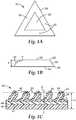
- an exemplary shaped abrasive particle 20 with a sloping sidewall 22is illustrated.
- the material from which the shaped abrasive particle 20 with a sloping sidewall 22 is madecomprises alpha alumina.
- Alpha alumina particlescan be made from a dispersion of aluminum oxide monohydrate that is gelled, molded to shape, dried to retain the shape, calcined, and then sintered as discussed herein later.
- the shaped abrasive particle's shapeis retained without the need for a binder to form an agglomerate comprising abrasive particles in a binder that are then formed into a shaped structure.
- the shaped abrasive particles 20 with a sloping sidewall 22comprise thin bodies having a first face 24, and a second face 26 and having a thickness t.
- the first face 24 and the second face 26are connected to each other by at least one sloping sidewall 22.
- more than one sloping sidewall 22can be present and the slope or angle for each sloping sidewall 22 may be the same as shown in FIG. 1A or different as shown in FIG. 4A .
- the first face 24is substantially planar
- the second face 26is substantially planar
- both facesare substantially planar.
- the facescould be concave or convex. Additionally, an opening or aperture through the faces could be present.
- first face 24 and the second face 26are substantially parallel to each other. In other embodiments, the first face 24 and second face 26 can be nonparallel such that one face is sloped with respect to the other face and imaginary lines tangent to each face would intersect at a point.
- the sloping sidewall 22 of the shaped abrasive particle 20 with a sloping sidewall 22can vary and it generally forms the perimeter 29 of the first face 24 and the second face 26.
- the perimeter 29 of the first face 24 and second face 26is selected to be a geometric shape, and the first face 24 and the second face 26 are selected to have the same geometric shape, although, they differ in size with one face being larger than the other face.
- the perimeter 29 of first face 24 and the perimeter 29 of the second face 26was a triangular shape that is illustrated.
- a draft angle ⁇ between the second face 26 and the sloping sidewall 22 of the shaped abrasive particle 20can be varied to change the relative sizes of each face.
- the draft angle ⁇can be between 95 degrees to 130 degrees, or between 95 degrees to 125 degrees, or between 95 degrees to 120 degrees, or between 95 degrees to 115 degrees, or between 95 degrees to 110 degrees, or between 95 degrees to 105 degrees, or between 95 degrees to 100 degrees.
- specific ranges for the draft angle ⁇have been found to produce surprising increases in the grinding performance of coated abrasive articles made from the shaped abrasive particles with a sloping sidewall.
- a coated abrasive article 40having a first major surface 41 of a backing 42 covered by an abrasive layer.
- the abrasive layercomprises a make coat 44, and a plurality of shaped abrasive particles 20 with a sloping sidewall 22 attached to the backing 42 by the make coat 44.
- a size coat 46is applied to further attach or adhere the shaped abrasive particles 20 with a sloping sidewall 22 to the backing 42.
- the majority of the shaped abrasive particles 20 with a sloping sidewall 22are tipped or leaning to one side. This results in the majority of the shaped abrasive particles 20 with a sloping sidewall 22 having an orientation angle ⁇ less than 90 degrees relative to the first major surface 41 of the backing 42.
- This resultis unexpected since the electrostatic coating method of applying the shaped abrasive particles with a sloping sidewall tends to originally orientate the particles at an orientation angle ⁇ of 90 degrees when they are first applied to the backing.
- the electrostatic fieldtends to align the particles vertically when applying them to the backing that is located above the shaped abrasive particles with a sloping sidewall.
- the electrostatic fieldtends to accelerate and drive the particles into the make coat at the 90 degree orientation.
- the particles under the force of gravity or the surface tension of the make and/or size coattend to lean over and come to rest on the sloping sidewall 22. It is believed that sufficient time in the process of making the coated abrasive article is present for the shaped abrasive particles to lean over and become attached to the make coat by the sloping sidewall 22 before the make coat and size coat cure and harden preventing any further rotation.
- the very tips 48 of the shaped abrasive particleshave generally the same height, h.
- the shaped abrasive particles with a sloping sidewallare applied in the backing in an open coat abrasive layer.
- a closed coat abrasive layeris defined as the maximum weight of abrasive particles or a blend of abrasive particles that can be applied to a make coat of an abrasive article in a single pass through the maker.
- An open coatis an amount of abrasive particles or a blend of abrasive particles, weighing less than the maximum weight in grams that can be applied, that is applied to a make coat of a coated abrasive article.
- an open coat abrasive layerwill result in less than 100% coverage of the make coat with abrasive particles thereby leaving open areas and a visible resin layer between the particles as best seen in FIG. 3 .
- the percent open area in the abrasive layercan be between 10% to 90% or between 30% to 80%.
- shaped abrasive particles with a sloping sidewallare applied to the backing, insufficient spaces between the particles will be present to allow from them to lean or tip prior to curing the make and size coats.
- greater than 50, 60, 70, 80, or 90 percent of the shaped abrasive particles in the coated abrasive article having an open coat abrasive layerare tipped or leaning having an orientation angle ⁇ of less than 90 degrees.
- an orientation angle ⁇ less than 90 degreesresults in enhanced cutting performance of the shaped abrasive particles with a sloping sidewall. Surprisingly, this result tends to occur regardless of the shaped abrasive particles' rotational orientation about the Z axis within the coated abrasive article. While FIG. 1C is idealized to show all the particles aligned in the same direction, an actual coated abrasive disc would have the particles randomly distributed and rotated as best seen in FIG. 3 .
- some shaped abrasive particleswill be driven into the workpiece at an orientation angle ⁇ of less than 90 degrees with the workpiece initially striking the second face 26 while a neighboring shaped abrasive particle could be rotated exactly 180 degrees with the workpiece striking backside of the shaped abrasive particle and the first face 24.
- ⁇orientation angle
- less than half of the shaped abrasive particlescould have the workpiece initially striking the second face 26 instead of the first face 24.
- the orientation angle ⁇ for at least a majority of the shaped abrasive particles with a sloping sidewall in an abrasive layer of a coated abrasive articlecan be between 50 degrees to 85 degrees, or between 55 degrees to 85 degrees, or between 60 degrees to 85 degrees, or between 65 degrees to 85 degrees, or between 70 degrees to 85 degrees, or between 75 degrees to 85 degrees, or between 80 degrees to 85 degrees.
- FIGS. 2 and 3photomicrographs of shaped abrasive particles 20 with a sloping sidewall 22 are shown.
- the draft angle ⁇is approximately 120 degrees and the shaped abrasive particles comprised an equilateral triangle. The sides of each triangle measured approximately 1.6 mm at the perimeter of the larger first face 24. The shaped abrasive particles had a thickness of approximately 0.38 mm.
- the surface of the resulting coated abrasive disc made from the shaped abrasive particles of FIG. 2is shown in FIG. 3 . As seen, the majority of the shaped abrasive particles are resting in the make coat on one of the sloping sidewalls.
- the orientation angle ⁇ for the majority of the shaped abrasive particles with a sloping sidewall in the abrasive layer of the coated abrasive article in FIG. 3is approximately 60 degrees.
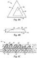
- a second embodiment of the shaped abrasive particle 20 with a sloping sidewall 22is illustrated.
- the material from which the shaped abrasive particle 20 with a sloping sidewall 22 is madecomprises alpha alumina.
- Alpha alumina particlescan be made from a dispersion of aluminum oxide monohydrate that is gelled, molded to shape, dried to retain the shape, calcined, and then sintered as discussed herein later.
- the shaped abrasive particle's shapeis retained without the need for a binder to form an agglomerate comprising abrasive particles in a binder that are then formed into a shaped structure.
- the shaped abrasive particles 20 with a sloping sidewall 22comprise thin bodies having a first face 24, and a second face 26 and having a thickness t.
- the first face 24 and the second face 26are connected to each other by at least a first sloping sidewall 50 having a first draft angle 52 and by a second sloping sidewall 54 having a second draft angle 56, which is selected to be a different value from the first draft angle.
- the first and second facesare also connected by a third sloping sidewall 58 having a third draft angle 60, which is a different value from either of the other two draft angles.
- the first, second and third draft anglesare all different values from each other.
- the first draft angle 52could be 120 degrees
- the second draft angle 56could be 110 degrees
- the third draft angle 60could be 100 degrees.
- the resulting coated abrasive article 40, as shown in FIG. 4Cmade from the shaped abrasive particles with the three different draft angles will tend to have an even distribution of shaped abrasive particles landing on each of the three different sloping sidewalls.
- the coated abrasive articlewill tend to have three distinct heights for the tips 48 of the shaped abrasive particles from the backing.
- the first sloping sidewall 50 contacting the make coat with the largest draft anglewill have the lowest tip height, hi
- the second sloping sidewall 54 with the intermediate draft anglewill have an intermediate tip height, h2
- the third sloping sidewall, 58, with the smallest draft anglewill have the highest tip height, h3.
- the coated abrasive articlewill possess shaped abrasive particles having three distinct orientation angles ⁇ relative to the backing and three distinct tip heights.
- Such a coated abrasive articlewill possess more uniform cutting performance as the abrasive article wears due to the unused shorter tips of the shaped abrasive particles coming into contact with the workpiece as the taller tips of the shaped abrasive particles tend to wear down and dull.
- the first face 24is substantially planar
- the second face 26is substantially planar
- both facesare substantially planar.
- the facescould be concave or convex. Additionally, an opening or aperture through the faces could be present.
- first face 24 and the second face 26are substantially parallel to each other. In other embodiments, the first face 24 and second face 26 can be nonparallel such that one face is sloped with respect to the other face and imaginary lines tangent to each face would intersect at a point.
- the first, second, and third sloping sidewalls of the shaped abrasive particle 20 with a sloping sidewall 22can vary and they generally form the perimeter 29 of the first face 24 and the second face 26.
- the perimeter 29 of the first face 24 and the second face 26is selected to be a geometric shape, and the first face 24 and the second face 26 are selected to have the same geometric shape, although, they differ in size with one face being larger than the other face.
- the perimeter 29 of first face 24 and the perimeter 29 of the second face 26was a triangular shape that is illustrated.
- the first, second, and third, draft angles between the second face 26 and the respective sloping sidewall of the shaped abrasive particle 20can be varied with at least two of the draft angles being different values, and desirably all three being different values.
- the first draft angle, the second draft angle, and the third draft anglecan be between about 95 degrees to about 130 degrees, or between about 95 degrees to about 125 degrees, or between about 95 degrees to about 120 degrees, or between about 95 degrees to about 115 degrees, or between about 95 degrees to about 110 degrees, or between about 95 degrees to about 105 degrees, or between about 95 degrees to about 100 degrees.
- a coated abrasive article 40having a first major surface 41 of a backing 42 covered by an abrasive layer.
- the abrasive layercomprises a make coat 44, and a plurality of shaped abrasive particles 20 with either the first, the second, or the third sloping sidewall attached to the backing 42 by the make coat 44.
- a size coat 46is applied to further attach or adhere the shaped abrasive particles 20 with a sloping sidewall 22 to the backing 42.
- the majority of the shaped abrasive particles 20 with a sloping sidewall 22are tipped or leaning to one side. This results in the majority of the shaped abrasive particles 20 with a sloping sidewall 22 having an orientation angle ⁇ less than 90 degrees relative to the first major surface 41 of the backing 42 as previously discussed for the first embodiment.
- the shaped abrasive particles with a sloping sidewallare applied in the backing in an open coat abrasive layer.
- An open coat abrasive layerwill result in less than 100% coverage of the make coat with abrasive particles thereby leaving open areas and a visible resin layer between the abrasive particles as best seen in FIG. 3 .
- the percent open area in the abrasive layercan be between 10% to 90% or between 30% to 80%.
- the orientation angle ⁇ for at least a majority of the shaped abrasive particles with a sloping sidewall in an abrasive layer of a coated abrasive articlecan be between 50 degrees to 85 degrees, or between 55 degrees to 85 degrees, or between 60 degrees to 85 degrees, or between 65 degrees to 85 degrees, or between 70 degrees to 85 degrees, or between 75 degrees to 85 degrees, or between 80 degrees to 85 degrees.
- the sloping sidewall 22is defined by a radius, R, instead of the draft angle ⁇ for the embodiment shown in FIGS. 1A-1C .
- a sloping sidewall 22 defined by a radius, Rhas also been found to result in the shaped abrasive particles 20 tipping or leaning when forming a coated abrasive article as shown in FIG. 5C .
- shaped abrasive particlescomprising an equilateral triangle with the sides of each triangle measuring approximately 1.6 mm at the perimeter of the larger first face 24, and having a thickness of approximately 0.38 mm, have the same cut performance with a draft angle of 120 degrees or a radius, R, of 0.51 mm.
- the radius, Rcan be between 0.5 to 2 times the thickness, t, of the shaped abrasive particle.
- the radius, Rcan be varied for each of the sidewalls to result in shaped abrasive particles leaning or tipping to varying degrees in the coated abrasive article.
- the shaped abrasive particles 20 with a sloping sidewall 22can have various three-dimensional shapes.
- the geometric shape of the perimeter 29can be triangular, rectangular, circular, elliptical, star-shaped or that of other regular or irregular polygons.
- an equilateral triangleis used and in another embodiment, an isosceles triangle is used.
- a substantially triangular shapealso includes three-sided polygons wherein one or more of the sides can be arcuate and/or the tips of the triangle can be arcuate.
- the various sloping sidewalls of the shaped abrasive particlescan have the same draft angle or different draft angles.
- a draft angle of 90 degreescan be used on one or more sidewalls as long as one of the sidewalls is a sloping sidewall having a draft angle of 95 degrees or greater.
- the shaped abrasive particles 20 with a sloping sidewallcan have various volumetric aspect ratios.
- the volumetric aspect ratiois defined as the ratio of the maximum cross sectional area passing through the centroid of a volume divided by the minimum cross sectional area passing through the centroid.
- the maximum or minimum cross sectional areamay be a plane tipped, angled, or tilted with respect to the external geometry of the shape.
- a spherewould have a volumetric aspect ratio of 1.000 while a cube will have a volumetric aspect ratio of 1.414.
- a shaped abrasive particle in the form of an equilateral triangle having each side equal to length A and a uniform thickness equal to Awill have a volumetric aspect ratio of 1.54, and if the uniform thickness is reduced to 0.25A, the volumetric aspect ratio is increased to 2.64. It is believed that shaped abrasive particles having a larger volumetric aspect ratio have enhanced cutting performance.
- the volumetric aspect ratio for the shaped abrasive particles with a sloping sidewallcan be greater than 1.15, or greater than 1.50, or greater than 2.0, or between 1.15 to 10.0, or between 120 to 5.0, or between 1.30 to 3.0.
- the shaped abrasive particles with a sloping sidewallcan have a much smaller radius of curvature at the points or corners of the shaped abrasive particles.
- the equilateral triangular shaped abrasive particles disclosed in U.S. 5,366,523 to Rowenhorst et al. and pictured in FIG. 8had a radius of curvature for the points of the triangle (measured from one side around the point to the next side) of 103.6 microns for the average tip radius.
- the radius of curvaturecan be measured from a polished cross-section of the first or second face using image analysis such as a Clemex Image Analysis program interfaced with an inverted light microscope or other suitable image analysis software.
- the radius of curvature for each triangular apexcan be estimated by defining three points at each apex when viewed in cross section at 100X magnification. A point is placed at the start of the tip's curve where there is a transition from the straight edge to the start of a curve, at the apex of the tip, and at the transition from the curved tip back to a straight edge.
- the image analysis softwarethen draws an arc defined by the three points (start, middle, and end of the curve) and calculates a radius of curvature.
- the radius of curvature for at least 30 apexesare measured and averaged to determine the average tip radius.
- the shaped abrasive particles made by the current methodare much more precisely made as best seen by comparing FIG.
- the average tip radius for the shaped abrasive particlesis much less.
- the average tip radius for shaped abrasive particles made according to the present disclosurehas been measured to be less than 19.2 microns.
- the average tip radiuscan be less than 75 microns, or less than 50 microns, or less than 25 microns. It is believed that a sharper tip promotes more aggressive cutting an improved fracturing of the shaped abrasive particles during use.
- the shaped abrasive particlescan have a much more precisely defined sidewall.
- FIGS. 9 and 10photomicrographs of polished cross sections taken perpendicular through the faces of the prior art shaped abrasive particles of FIG. 8 are shown.
- the sidewalltop surface
- the same sidewallmay transition from one shape to another.
- the sidewallin the foreground the sidewall is convex while in the background it is concave.
- FIG. 11a polished cross section taken perpendicular through the faces of a shaped abrasive particle with a sloping sidewall having a 98 degree draft angle is shown.
- the first face 24(right hand vertical surface) is concave as disclosed in the pending patent application attorney docket number 64716US002 referred to above. A concave surface is thought to enhance grinding performance by removing more material during use similar to a scoop, spoon, or hollow ground chisel blade.
- the second face 26is substantially planar (left hand vertical surface).
- the sidewall (top surface)is uniformly planar.
- uniformly planarit is meant that the sidewall does not have areas that are convex from one face to the other face, or areas that are concave from one face to the other face and at least 50%, or at least 75%, or at least 85% or more of the sidewall surface is planar.
- a substantially linear edgeappears (where the top sidewall surface meets the cut cross section's front surface).
- the uniformly planar sidewallwould typically have that substantially linear edge at substantially all cross sectional planes along the length of the sidewall.
- the uniformly planar sidewallprovides better defined (sharper) edges where the sidewall intersects with the first face and the second face, and this is also thought to enhance grinding performance.
- Shaped abrasive particles 20 with a sloping sidewall 22 made according to the present disclosurecan be incorporated into an abrasive article, or used in loose form.
- Abrasive particlesare generally graded to a given particle size distribution before use. Such distributions typically have a range of particle sizes, from coarse particles to fine particles. In the abrasive art this range is sometimes referred to as a "coarse", "control”, and "fine” fractions.
- Abrasive particles graded according to abrasive industry accepted grading standardsspecify the particle size distribution for each nominal grade within numerical limits. Such industry accepted grading standards (i.e., abrasive industry specified nominal grade) include those known as the American National Standards Institute, Inc. (ANSI) standards, Federation of European Producers of Abrasive Products (FEPA) standards, and Japanese Industrial Standard (JIS) standards.
- ANSIAmerican National Standards Institute, Inc.
- FEPAFederation of European Producers of Abrasive Products
- JISJapanese Industrial Standard
- ANSI grade designationsinclude: ANSI 4, ANSI 6, ANSI 8, ANSI 16, ANSI 24, ANSI 36, ANSI 40, ANSI 50, ANSI 60, ANSI 80, ANSI 100, ANSI 120, ANSI 150, ANSI 180, ANSI 220, ANSI 240, ANSI 280, ANSI 320, ANSI 360, ANSI 400, and ANSI 600.
- FEPA grade designationsinclude P8, P12, P16, P24, P36, P40, P50, P60, P80, P100, P120, P150, P180, P220, P320, P400, P500, P600, P800, P1000, and P1200.
- JIS grade designationsinclude JIS8, JIS12, JIS16, JIS24, JIS36, JIS46, JIS54, JIS60, JIS80, JIS100, JIS150, JIS180, JIS220, JIS240, JIS280, JIS320, JIS360, JIS400, JIS600, JIS800, JIS 1000, JIS1500, JIS2500, JIS4000, JIS6000, JIS8000, and JIS10,000.
- the shaped abrasive particles 20 with a sloping sidewall 22can graded to a nominal screened grade using U.S.A. Standard Test Sieves conforming to ASTM E-11 "Standard Specification for Wire Cloth and Sieves for Testing Purposes.”
- ASTM E-11proscribes the requirements for the design and construction of testing sieves using a medium of woven wire cloth mounted in a frame for the classification of materials according to a designated particle size.
- a typical designationmay be represented as - 18+20 meaning that the shaped abrasive particles 20 pass through a test sieve meeting ASTM E-11 specifications for the number 18 sieve and are retained on a test sieve meeting ASTM E-11 specifications for the number 20 sieve.
- the shaped abrasive particles 20 with a sloping sidewall 22have a particle size such that most of the particles pass through an 18 mesh test sieve and can be retained on a 20, 25, 30, 35, 40, 45, or 50 mesh test sieve.
- the shaped abrasive particles 20 with a sloping sidewall 22can have a nominal screened grade comprising: -18+20, -20+25, -25+30, -30+35, -35+40, -40+45, -45+50, -50+60, -60+70, - 70+80, -80+100, -100+120, -120+140, -140+170, -170+200, -200+230, -230+270, - 270+325, -325+400, -400+450,-450+500, or -500+635.
- the present disclosureprovides a plurality of shaped abrasive particles having an abrasives industry specified nominal grade or nominal screened grade, wherein at least a portion of the plurality of abrasive particles are shaped abrasive particles 20 with a sloping sidewall 22.
- the disclosureprovides a method comprises grading the shaped abrasive particles 20 with a sloping sidewall 22 made according to the present disclosure to provide a plurality of shaped abrasive particles 20 with a sloping sidewall 22 having an abrasives industry specified nominal grade or a nominal screened grade.
- the shaped abrasive particles 20 with a sloping sidewall 22 having an abrasives industry specified nominal grade or a nominal screened gradecan be mixed with other known abrasive or non-abrasive particles.
- at least 5, 10, 15, 20, 25, 30, 35, 40, 45, 50, 55, 60, 65, 70, 75, 80, 85, 90, 95, or even 100 percent by weight of the plurality of abrasive particles having an abrasives industry specified nominal grade or a nominal screened gradeare shaped abrasive particles 20 with a sloping sidewall 22 made according to the present disclosure, based on the total weight of the plurality of abrasive particles.
- Particles suitable for mixing with the shaped abrasive particles 20 with a sloping sidewall 22include conventional abrasive grains, diluent grains, or erodable agglomerates, such as those described in U.S. Pat. Nos. 4,799,939 and 5,078,753 .
- Representative examples of conventional abrasive grainsinclude fused aluminum oxide, silicon carbide, garnet, fused alumina zirconia, cubic boron nitride, diamond, and the like.
- Representative examples of diluent grainsinclude marble, gypsum, and glass.
- Blends of differently shaped abrasive particles 20 with a sloping sidewall 22can be used in the articles of this invention.
- blends of shaped abrasive particles 20 with different draft anglesfor example particles having an 98 degree draft angle mixed with particles having a 120 degree draft angle
- the shaped abrasive particles 20 with a sloping sidewall 22may also have a surface coating.
- Surface coatingsare known to improve the adhesion between abrasive grains and the binder in abrasive articles or can be used to aid in electrostatic deposition of the shaped abrasive particles 20. Such surface coatings are described in U.S. patent numbers 5,213,591 ; 5,011,508 ; 1,910,444 ; 3,041,156 ; 5,009,675 ; 5,085,671 ; 4,997,461 ; and 5,042,991 . Additionally, the surface coating may prevent the shaped abrasive particle from capping. Capping is the term to describe the phenomenon where metal particles from the workpiece being abraded become welded to the tops of the shaped abrasive particles. Surface coatings to perform the above functions are known to those of skill in the art.
- a coated abrasive article 40comprises a backing 42 having a first layer of binder, hereinafter referred to as the make coat 44, applied over a first major surface 41 of backing 42. Attached or partially embedded in the make coat 44 are a plurality of shaped abrasive particles 20 with a sloping sidewall 22 forming an abrasive layer. Over the shaped abrasive particles 20 with a sloping sidewall 22 is a second layer of binder, hereinafter referred to as the size coat 46.
- make coat 44is to secure shaped abrasive particles 20 with n sloping sidewall 22 to backing 42 and the purpose of size coat 46 is to reinforce shaped abrasive particles 20 with a sloping sidewall 22.
- the majority of the shaped abrasive particles 20 with a sloping sidewall 22are oriented such that the tip 48 or vertex points away from the backing 42 and the shaped abrasive particles are resting on the sloping sidewall 22 and tipped or leaning as shown.
- the make coat 44 and size coat 46comprise a resinous adhesive.
- the resinous adhesive of the make coat 44can be the same as or different from that of the size coat 46.
- resinous adhesivesthat are suitable for these coats include phenolic resins, epoxy resins, urea-formaldehyde resins, acrylate resins, aminoplast resins, melamine resins, acrylated epoxy resins, urethane resins and combinations thereof.
- the make coat 44 or size coat 46, or both coatsmay further comprise additives that are known in the art, such as, for example, fillers, grinding aids, wetting agents, surfactants, dyes, pigments, coupling agents, adhesion promoters, and combinations thereof.
- fillersinclude calcium carbonate, silica, talc, clay, calcium metasilicate, dolomite, aluminum sulfate and combinations thereof.
- a grinding aidcan be applied to the coated abrasive article.
- a grinding aidis defined as particulate material, the addition of which has a significant effect on the chemical and physical processes of abrading, thereby resulting in improved performance.
- Grinding aidsencompass a wide variety of different materials and can be inorganic or organic. Examples of chemical groups of grinding aids include waxes, organic halide compounds, halide salts, and metals and their alloys. The organic halide compounds will typically break down during abrading and release a halogen acid or a gaseous halide compound. Examples of such materials include chlorinated waxes, such as tetrachloronaphthalene, pentachloronaphthalene; and polyvinyl chloride.
- halide saltsinclude sodium chloride, potassium cryolite, sodium cryolite, ammonium cryolite, potassium tetrafluoroborate, sodium tetrafluoroborate, silicon fluorides, potassium chloride, magnesium chloride.
- metalsinclude tin, lead, bismuth, cobalt, antimony, cadmium, iron, and titanium.
- Other grinding aidsinclude sulfur, organic sulfur compounds, graphite, and metallic sulfides. It is also within the scope of this invention to use a combination of different grinding aids; in some instances, this may produce a synergistic effect. In one embodiment, the grinding aid was cryolite or potassium tetrafluoroborate. The amount of such additives can be adjusted to give desired properties.
- the supersize coatingtypically contains a binder and a grinding aid.
- the binderscan be formed from such materials as phenolic resins, acrylate resins, epoxy resins, urea-formaldehyde resins, melamine resins, urethane resins, and combinations thereof.
- the shaped abrasive particles 20 with a sloping sidewall 22can be utilized in a bonded abrasive article, a nonwoven abrasive article, or abrasive brushes.
- a bonded abrasivecan comprises a plurality of the shaped abrasive particles 20 with a sloping sidewall 22 bonded together by means of a binder to form a shaped mass.
- the binder for a bonded abrasivecan be metallic, organic, or vitreous.
- a nonwoven abrasivecomprises a plurality of the shaped abrasive particles 20 with a sloping sidewall 22 bonded into a fibrous nonwoven web by means of an organic binder.
- the first process stepinvolves providing either a seeded on un-seeded abrasive dispersion that can be converted into alpha alumina.
- the alpha alumina precursor compositionoften comprises a liquid that is a volatile component.
- the volatile componentis water.
- the abrasive dispersionshould comprise a sufficient amount of liquid for the viscosity of the abrasive dispersion to be sufficiently low to enable filling the mold cavities and replicating the mold surfaces, but not so much liquid as to cause subsequent removal of the liquid from the mold cavity to be prohibitively expensive.
- the abrasive dispersioncomprises from 2 percent to 90 percent by weight of the particles that can be converted into alpha alumina, such as particles of aluminum oxide monohydrate (boehmite), and at least 10 percent by weight, or from 50 percent to 70 percent, or 50 percent to 60 percent, by weight of the volatile component such as water.
- the abrasive dispersionin some embodiments contains from 30 percent to 50 percent, or 40 percent to 50 percent, by weight solids.
- Boehmitecan be prepared by known techniques or can be obtained commercially. Examples of commercially available boehmite include products having the trademarks "DISPERAL”, and “DISPAL”, both available from Sasol North America, Inc. or "HiQ-40” available from BASF Corporation. These aluminum oxide monohydrates are relatively pure, i.e., they include relatively little, if any, hydrate phases other than monohydrates, and have a high surface area. The physical properties of the resulting shaped abrasive particles 20 with a sloping sidewall 22 will generally depend upon the type of material used in the abrasive dispersion.
- the abrasive dispersionis in a gel state.
- a "gel”is a three dimensional network of solids dispersed in a liquid.
- the abrasive dispersionmay contain a modifying additive or precursor of a modifying additive.
- the modifying additivecan function to enhance some desirable property of the abrasive particles or increase the effectiveness of the subsequent sintering step.
- Modifying additives or precursors of modifying additivescan be in the form of soluble salts, typically water soluble salts.
- Theytypically consist of a metal-containing compound and can be a precursor of oxide of magnesium, zinc, iron, silicon, cobalt, nickel, zirconium, hafnium, chromium, yttrium, praseodymium, samarium, ytterbium, neodymium, lanthanum, gadolinium, cerium, dysprosium, erbium, titanium, and mixtures thereof.
- concentrations of these additives that can be present in the abrasive dispersioncan be varied based on skill in the art.
- the introduction of a modifying additive or precursor of a modifying additivewill cause the abrasive dispersion to gel.
- the abrasive dispersioncan also be induced to gel by application of heat over a period of time.
- the abrasive dispersioncan also contain a nucleating agent to enhance the transformation of hydrated or calcined aluminum oxide to alpha alumina.
- Nucleating agents suitable for this disclosureinclude fine particles of alpha alumina, alpha ferric oxide or its precursor, titanium oxides and titanates, chrome oxides, or any other material that will nucleate the transformation. The amount of nucleating agent, if used, should be sufficient to effect the transformation of alpha alumina. Nucleating such abrasive dispersions is disclosed in U.S. patent number 4,744,802 to Schwabel .
- a peptizing agentcan be added to the abrasive dispersion to produce a more stable hydrosol or colloidal abrasive dispersion.
- Suitable peptizing agentsare monoprotic acids or acid compounds such as acetic acid, hydrochloric acid, formic acid, and nitric acid. Multiprotic acids can also be used but they can rapidly gel the abrasive dispersion, making it difficult to handle or to introduce additional components thereto.
- Some commercial sources of boehmitecontain an acid titer (such as absorbed formic or nitric acid) that will assist in forming a stable abrasive dispersion.
- the abrasive dispersioncan be formed by any suitable means, such as, for example, simply by mixing aluminum oxide monohydrate with water containing a peptizing agent or by forming an aluminum oxide monohydrate slurry to which the peptizing agent is added. Defoamers or other suitable chemicals can be added to reduce the tendency to form bubbles or entrain air while mixing. Additional chemicals such as wetting agents, alcohols, or coupling agents can be added if desired.
- the alpha alumina abrasive grainmay contain silica and iron oxide as disclosed in U.S, patent number 5,645,619 to Erickson et al. on July 8, 1997 .
- the alpha alumina abrasive grainmay contain zirconia as disclosed in U.S.
- the alpha alumina abrasive graincan have a microstructure or additives as disclosed in U.S. patent number 6,277,161 to Castro on August 21, 2001 .
- the second process stepinvolves providing a mold having at least one mold cavity, and preferably a plurality of cavities.
- the moldcan have a generally planar bottom surface and a plurality of mold cavities.
- the plurality of cavitiescan be formed in a production tool.
- the production toolcan be a belt, a sheet, a continuous web, a coating roll such as a rotogravure roll, a sleeve mounted on a coating roll, or die.
- the production toolcomprises polymeric material.
- suitable polymeric materialsinclude thermoplastics such as polyesters, polycarbonates, poly(ether sulfone), poly(methyl methacrylate), polyurethanes, polyvinylchloride, polyolefins, polystyrene, polypropylene, polyethylene or combinations thereof, or thermosetting materials.
- the entire toolingis made from a polymeric or thermoplastic material.
- the surfaces of the tooling in contact with the sol-gel while drying, such as the surfaces of the plurality of cavitiescomprises polymeric or thermoplastic materials and other portions of the tooling can be made from other materials.
- a suitable polymeric coatingmay be applied to a metal tooling to change its surface tension properties by way of example.
- a polymeric or thermoplastic toolcan be replicated off a metal master tool.
- the master toolwill have the inverse pattern desired for the production tool.
- the master toolcan be made in the same manner as the production tool.
- the master toolis made out of metal, e.g., nickel and is diamond turned.
- the polymeric sheet materialcan be heated along with the master tool such that the polymeric material is embossed with the master tool pattern by pressing the two together.
- a polymeric or thermoplastic materialcan also be extruded or cast onto the master tool and then pressed.
- the thermoplastic materialis cooled to solidify and produce the production tool. If a thermoplastic production tool is utilized, then care should be taken not to generate excessive heat that may distort the thermoplastic production tool limiting its life.
- Access to cavitiescan be from an opening in the top surface or bottom surface of the mold.
- the cavitycan extend for the entire thickness of mold.
- the cavitycan extend only for a portion of the thickness of the mold.
- the top surfaceis substantially parallel to bottom surface of the mold with the cavities having a substantially uniform depth.
- At least one side of the mold, i.e. the side in which the cavity is formed,can remain exposed to the surrounding atmosphere during the step in which the volatile component is removed.
- the cavityhas a specified three-dimensional shape.
- the shape of a cavitycan be described as being a triangle, as viewed from the top, having a sloping sidewall such that the bottom surface of the cavity is slightly smaller than the opening in the top surface.
- a sloping sidewallis believed to enhance grinding performance and enable easier removal of the precursor abrasive particles from the mold.
- the moldcomprised a plurality of triangular cavities. Each of the plurality of triangular cavities comprises an equilateral triangle.
- cavity shapescan be used, such as, circles, rectangles, squares, hexagons, stars, or combinations thereof, all having a substantially uniform depth dimension.
- the depth dimensionis equal to the perpendicular distance from the top surface to the lowermost point on the bottom surface.
- the depth of a given cavitycan be uniform or can vary along its length and/or width.
- the cavities of a given moldcan be of the same shape or of different shapes.
- the third process stepinvolves filling the cavities in the mold with the abrasive dispersion by any conventional technique.
- a knife roll coater or vacuum slot die coatercan be used.
- a mold releasecan be used to aid in removing the particles from the mold if desired.
- Typical mold release agentsinclude oils such as peanut oil or mineral oil, fish oil, silicones, polytetrafluoroethylene, zinc sterate, and graphite.
- mold release agentsuch as peanut oil
- a liquidsuch as water or alcohol
- mold release agentsuch as peanut oil
- a liquidsuch as water or alcohol
- the top surface of the moldis coated with the abrasive dispersion.
- the abrasive dispersioncan be pumped onto top surface.
- a scraper or leveler barcan be used to force the abrasive dispersion fully into the cavity of the mold.
- the remaining portion of the abrasive dispersion that does not enter cavitycan be removed from top surface of the mold and recycled.
- a small portion of the abrasive dispersioncan remain on top surface and in other embodiments the top surface is substantially free of the dispersion.
- the pressure applied by the scraper or leveler baris typically less than 100 psi, or less than 50 psi, or less than 10 psi.
- no exposed surface of the abrasive dispersionextends substantially beyond the top surface to ensure uniformity in thickness of the resulting shaped abrasive particles 20.
- the fourth process stepinvolves removing the volatile component to dry the dispersion.
- the volatile componentis removed by fast evaporation rates.
- removal of the volatile component by evaporationoccurs at temperatures above the boiling point of the volatile component.
- An upper limit to the drying temperatureoften depends on the material the mold is made from. For polypropylene tooling the temperature should be less than the melting point of the plastic.
- the drying temperaturescan be between 90 degrees C to 165 degrees C, or between 105 degrees C to 150 degrees C, or between 105 degrees C to 120 degrees C. Higher temperatures can lead to the formation of larger openings but can also lead to degradation of the polypropylene tooling limiting its useful life as a mold.
- a sample of boehmite sol-gelwas made using the following recipe: aluminum oxide monohydrate powder (1600 parts) having the trade designation "DISPERAL” was dispersed by high shear mixing a solution containing water (2400 parts) and 70% aqueous nitric acid (72 parts) for 11 minutes. The resulting sol-gel was aged for at least 1 hour before coating. The sol-gel was forced into production tooling having triangular shaped mold cavities of 28 mils depth and 110 mils on each side and having a sloping sidewall having a predetermined draft angel ⁇ between the sidewall and bottom of the mold.
- the sol-gelwas forced into the cavities with a putty knife so that the openings of the production tooling were completely filled.
- a mold release agent, 1% peanut oil in methanolwas used to coat the production tooling such that 0.5 mg/in 2 of peanut oil was applied to the mold surfaces.
- the excess methanolwas removed by placing sheets of the production tooling in an air convection oven for 5 minutes at 45 C.
- the sol-gel coated production toolingwas placed in an air convection oven at 45 C for at least 45 minutes to dry.
- the precursor shaped abrasive particleswere removed from the production tooling by passing it over an ultrasonic horn. These precursor shaped abrasive particles can be fired to produce shaped abrasive particles 20 with a sloping sidewall 22.
- the fifth process stepinvolves removing the precursor shaped abrasive particles with a sloping sidewall from the mold cavities.
- the precursor shaped abrasive particles with a sloping sidewallcan be removed from the cavities by using the following processes alone or in combination on the mold: gravity, vibration, ultrasonic vibration, vacuum, or pressurized air to remove the particles from the mold cavities.
- the precursor abrasive particles with a sloping sidewallcan be further dried outside of the mold. If the abrasive dispersion is dried to the desired level in the mold, this additional drying step is not necessary. However, in some instances it may be economical to employ this additional drying step to minimize the time that the abrasive dispersion resides in the mold.
- the precursor shaped abrasive particleswill be dried from 10 to 480 minutes, or from 120 to 400 minutes, at a temperature from 50 degrees C to 160 degrees C, or at 120 degrees C to 150 degrees C.
- the sixth process stepinvolves calcining the precursor shaped abrasive particles with a sloping sidewall 22.
- calciningessentially all the volatile material is removed, and the various components that were present in the abrasive dispersion are transformed into metal oxides.
- the precursor shaped abrasive particlesare generally heated to a temperature from 400 degrees C to 800 degrees C, and maintained within this temperature range until the free water and over 90 percent by weight of any bound volatile material are removed.
- a water-soluble saltcan be introduced by impregnation into the pores of the calcined, precursor shaped abrasive particles. Then the precursor shaped abrasive particles are prefired again. This option is further described in European Patent Application No. 293,163 .
- the seventh process stepinvolves sintering the calcined, precursor shaped abrasive particles to form alpha alumina particles.
- the calcined, precursor shaped abrasive particlesPrior to sintering, the calcined, precursor shaped abrasive particles are not completely densified and thus lack the desired hardness to be used as shaped abrasive particles.
- Sinteringtakes place by heating the calcined, precursor shaped abrasive particles to a temperature of from 1,000 degrees C to 1,650 degrees C and maintaining them within this temperature range until substantially all of the alpha alumina monohydrate (or equivalent) is converted to alpha alumina and the porosity is reduced to less than 15 percent by volume.
- the length of time to which the calcined, precursor shaped abrasive particles must be exposed to the sintering temperature to achieve this level of conversiondepends upon various factors but usually from five seconds to 48 hours is typical. In another embodiment, the duration for the sintering step ranges from one minute to 90 minutes.
- the shaped abrasive particles with a sloping sidewallcan have a Vickers hardness of 10 GPa, 16 GPa, 18 GPa, 20 GPa, or greater.
- the processcan be modified by combining two or more of the process steps if desired.
- Conventional process steps that can be used to modify the process of this disclosureare more fully described in U.S. patent number 4,314,827 to Leitheiser .
- the shaped abrasive particles with a sloping sidewallcan have grooves on one of the faces. The grooves are formed by a plurality of ridges in the bottom surface of the mold cavity that have been found to make it easier to remove the precursor shaped abrasive particles from the mold.
- boehmite sol-gelwas made using the following recipe: aluminum oxide monohydrate powder (1600 parts) having the trade designation "DISPERAL" was dispersed by high shear mixing a solution containing water (2400 parts) and 70% aqueous nitric acid (72 parts) for 11 minutes. The resulting sol-gel was aged for at least 1 hour before coating. The sol-gel was forced into production tooling having triangular shaped mold cavities of 28 mils depth and 110 mils on each side. The draft angel ⁇ between the sidewall and bottom of the mold was different for each production tooling. The draft angle ⁇ was 90 degrees for the first tooling, 98 degrees for the second tooling, 120 degrees for the third tooling and 135 degrees for the last tooling.
- the 98 degree draft angle production toolingwas manufactured to have 50% of the mold cavities with 8 parallel ridges rising from the bottom surfaces of the cavities that intersected with one side of the triangle at a 90 degree angle and the remaining cavities had a smooth bottom mold surface.
- the parallel ridgeswere spaced every 0.277 mm and the cross section of the ridges was a triangle shape having a height of 0.0127 mm and a 45 degree angle between the sides of each ridge at the tip.
- the sol-gelwas forced into the cavities with a putty knife so that the openings of the production tooling were completely filled.
- a mold release agent, 1% peanut oil in methanolwas used to coat the production tooling with about 0.5mg/in 2 of peanut oil applied to the production tooling.
- the excess methanolwas removed by placing sheets of the production tooling in an air convection oven for 5 minutes at 45 degrees C.
- the sol-gel coated production toolingwas placed in an air convection oven at 45 degrees C for at least 45 minutes to dry.
- the precursor shaped abrasive particleswere removed from the production tooling by passing it over an ultrasonic horn.
- the precursor shaped abrasive particleswere calcined at approximately 650 degrees Celsius and then saturated with a mixed nitrate solution of the following concentration (reported as oxides): 1.8% each of MgO, Y 2 O 3 , Nd 2 O 3 and La 2 O 3 .
- the excess nitrate solutionwas removed and the saturated precursor shaped abrasive particles were allowed to dry after which the particles were again calcined at 650 degrees Celsius and sintered at approximately 1400 degrees Celsius. Both the calcining and sintering was performed using rotary tube kilns.
- coated abrasive discswere made.
- the shaped abrasive particles with sloping sidewallswere electrostatic coated onto a 7 inch diameter fiber disc with a 7/8 inch center hole using phenolic make coat and size coat resins as shown in Table 1.
- the phenolic resincan be made from resole phenol-formaldehyde resin, a 1.5:1 to 2.1:1 (phenol:formaldehyde) condensate catalyzed by 1 to 5% potassium hydroxide.
- the grinding performance of the shaped abrasive particles with a sloping sidewallwas evaluated by grinding 1045 medium carbon steel using the following procedure.
- 7-inch (17.8 cm) diameter abrasive discs for evaluationwere attached to a rotary grinder fitted with a 7-inch (17.8 cm) ribbed disc pad face plate ("80514 Extra Hard Red” obtained from 3M Company, St. Paul, Minnesota).
- the grinderwas then activated and urged against an end face of a 0.75 x 0.75 in (1.9 x 1.9 cm) pre-weighed 1045 steel bar under a load of 12 lb (5.4 kg).
- the resulting rotational speed of the grinder under this load and against this workpiecewas 5000 rpm.
- the workpiecewas abraded under these conditions for a total of fifty (50) 10-second grinding intervals (passes). Following each 10-second interval, the workpiece was allowed to cool to room temperature and weighed to determine the cut of the abrasive operation. Test results were reported as the incremental cut for each interval and the total cut removed. If desired, the testing can be automated using suitable equipment.
- the Cut Rate versus Time and the Total Cut versus Timeare plotted.
- shaped abrasive particles having a sloping sidewall with a draft angle greater than 90 degreessignificantly out performed similarly shaped abrasive particles having a 90 degree draft angle.
- the draft angleapproached 135 degrees
- the performance of the shaped abrasive particles with a sloping sidewallbegin to rapidly deteriorate.
- the initial cut ratewas similar but the total cut was significantly reduced.
- the shaped abrasive particles having a draft angle of 120 degreeshad approximately a 20% improvement in initial cut and approximately the same total cut as blend of shaped abrasive particles having a 98 degree draft angle (grooves and no grooves), which was unexpected. Even more surprising, shaped abrasive particles having only an 8 degree change in draft angle from 90 degrees to 98 degrees had a huge jump in performance. The initial cut rate was almost doubled and the cut rate remained relatively constant during the entire test duration. It is believed that the more consistent cut rate is a result of using a blend of 50% shaped abrasive particles with grooves and 50% shaped abrasive particles without grooves.
Landscapes
- Engineering & Computer Science (AREA)
- Chemical & Material Sciences (AREA)
- Mechanical Engineering (AREA)
- Manufacturing & Machinery (AREA)
- Materials Engineering (AREA)
- Organic Chemistry (AREA)
- Polishing Bodies And Polishing Tools (AREA)
Description
- Abrasive particles and abrasive articles made from the abrasive particles are useful for abrading, finishing, or grinding a wide variety of materials and surfaces in the manufacturing of goods. As such, there continues to be a need for improving the cost, performance, or life of the abrasive particle and/or the abrasive article.
- Triangular shaped abrasive particles and abrasive articles using the triangular shaped abrasive particles are disclosed in
U.S. patents 5,201,916 to Berg ;5,366,523 to Rowenhorst ; and5,984,988 to Berg . In one embodiment, the abrasive particles' shape comprised an equilateral triangle. Triangular shaped abrasive particles are useful in manufacturing abrasive articles having enhanced cut rates. EP 0 656 319 A2US 5,593,467 A to Monroe discloses crystalline ceramic, alpha alumina-based abrasive grain and a method of making the same. The abrasive grain can be incorporated into abrasive products such as coated abrasives, bonded wheels, and three dimensional, low density abrasives.- Shaped abrasive particles, in general, can have superior performance over randomly crushed abrasive particles. By controlling the shape of the abrasive particle it is possible to control the resulting performance of the abrasive article. The inventors have discovered that by making the shaped abrasive particle with a sloping sidewall having a draft angle between 95 degrees to 130 degrees several unexpected benefits occur.
- First, the shaped abrasive particles with the sloping sidewall tend to rest on the make coat of a coated abrasive article at an angle corresponding to the draft angle of the sidewall. It is believed that a draft angle other than 90 degrees results in the shaped abrasive particles leaning instead of having a 90 degree orientation to the backing in a coated abrasive article since the sidewall, which the shaped abrasive particle in the coated abrasive rests on, is sloped due to the draft angle. Because the shaped abrasive particles are mostly tipped or leaning to one side due to the angled sidewall they rest on, they can have an orientation angle less than 90 degrees relative to the backing thereby enhancing cut rates.
- Secondly, the shaped abrasive particles with the sloping sidewall can have different draft angles for different sides of the shaped abrasive particle. For example, an equilateral triangle can have a first sidewall at a first draft angle, a second sidewall at a second draft angle, and a third sidewall at a third draft angle, wherein the first, second, and third draft angles are different. A resulting coated abrasive article made from the shaped abrasive particles with the three different sidewall angles will tend to have an even distribution of particles landing on each of the three sidewalls. As such, the coated abrasive article will tend to have three distinct heights for the tips of the shaped abrasive particles from the backing. The sidewall contacting the make coat with the largest draft angle will have the lowest tip height, the sidewall with the intermediate draft angle will have an intermediate tip height, and the sidewall with the smallest draft angle will have the highest tip height. As a result, the coated abrasive article will possess shaped abrasive particles having three distinct orientation angles relative to the backing and three distinct tip heights. It is believed that such a coated abrasive article will possess more uniform cutting performance as the abrasive article wears due to the unused shorter tips of the shaped abrasive particles coming into contact with the workpiece as the taller tips of the shaped abrasive particles tend to wear down.
- Hence, in one embodiment, the disclosure resides abrasive particles comprising shaped abrasive particles each having a sloping sidewall, each of the shaped abrasive particles comprising alpha alumina and having a first face and a second face separated by a thickness, t. The shaped abrasive particles further comprising either: a draft angle α between the second face and the sloping sidewall, and the draft angle α is between 95 degrees to 130 degrees, or the sloping sidewall having a radius, R, between the first face and the second face and the radius, R, is between 0.5 to 2 times the thickness, t.
- It is to be understood by one of ordinary skill in the art that the present discussion is a description of exemplary embodiments only, and is not intended as limiting the broader aspects of the present disclosure, which broader aspects are embodied in the exemplary construction.
FIG. 1A illustrates a top view of one embodiment of a shaped abrasive particle.FIG. 1B illustrates a side view the shaped abrasive particle ofFIG. 1A .FIG. 1C illustrates a side view of coated abrasive article made from the shaped abrasive particles ofFIG. 1A .FIG. 2 illustrates a photomicrograph of the shaped abrasive particles.FIG. 3 illustrates a photomicrograph of the top surface of a coated abrasive article made from the shaped abrasive particles ofFIG. 2 .FIG. 4A illustrates a top view of another embodiment of a shaped abrasive particle.FIG. 4B illustrates a side view the shaped abrasive particle ofFIG. 4A .FIG. 4C illustrates a side view of coated abrasive article made from the shaped abrasive particles ofFIG. 4A .FIG. 5A illustrates a top view of another embodiment of a shaped abrasive particle.FIG. 5B illustrates a side view the shaped abrasive particle ofFIG. 5A .FIG. 5C illustrates a side view of coated abrasive article made from the shaped abrasive particles ofFIG. 5A .FIG. 6 illustrates a graph of Cut Rate versus Time for shaped abrasive particles with different draft angles.FIG. 7 illustrates a graph of Total Cut versus Time for shaped abrasive particles with different draft angles.FIG. 8 illustrates a photomicrograph of prior art abrasive particles made according toU.S. patent number 5,366,523 .FIG. 9 illustrates a photomicrograph of a cross section of the prior art abrasive particles ofFIG. 8 .FIG. 10 illustrates a photomicrograph of a cross section of the prior art abrasive particles ofFIG. 8 .FIG. 11 illustrates a photomicrograph of a cross section of a shaped abrasive particle with a sloping sidewall.- Repeated use of reference characters in the specification and drawings is intended to represent the same or analogous features or elements of the disclosure.
- As used herein, forms of the words "comprise", "have", and "include" are legally equivalent and open-ended. Therefore, additional non-recited elements, functions, steps or limitations may be present in addition to the recited elements, functions, steps, or limitations.
- As used herein, the term "abrasive dispersion" means an alpha alumina precursor that can be converted into alpha alumina that is introduced into a mold cavity. The composition is referred to as an abrasive dispersion until sufficient volatile components are removed to bring solidification of the abrasive dispersion.
- As used herein, the term "precursor shaped abrasive particle" means the unsintered particle produced by removing a sufficient amount of the volatile component from the abrasive dispersion, when it is in the mold cavity, to form a solidified body that can be removed from the mold cavity and substantially retain its molded shape in subsequent processing operations.
- As used herein, the term "shaped abrasive particle", means a ceramic abrasive particle with at least a portion of the abrasive particle having a predetermined shape that is replicated from a mold cavity used to form the shaped precursor abrasive particle. Except in the case of abrasive shards, the shaped abrasive particle will generally have a predetermined geometric shape that substantially replicates the mold cavity that was used to form the shaped abrasive particle. Shaped abrasive particle as used herein excludes abrasive particles obtained by a mechanical crushing operation.
- Referring to
FIGS. 1A, 1B, and 1C an exemplary shapedabrasive particle 20 with a slopingsidewall 22 is illustrated. The material from which the shapedabrasive particle 20 with a slopingsidewall 22 is made comprises alpha alumina. Alpha alumina particles can be made from a dispersion of aluminum oxide monohydrate that is gelled, molded to shape, dried to retain the shape, calcined, and then sintered as discussed herein later. The shaped abrasive particle's shape is retained without the need for a binder to form an agglomerate comprising abrasive particles in a binder that are then formed into a shaped structure. - In general, the shaped
abrasive particles 20 with a slopingsidewall 22 comprise thin bodies having afirst face 24, and asecond face 26 and having a thickness t. Thefirst face 24 and thesecond face 26 are connected to each other by at least one slopingsidewall 22. In some embodiments, more than one slopingsidewall 22 can be present and the slope or angle for eachsloping sidewall 22 may be the same as shown inFIG. 1A or different as shown inFIG. 4A . - In some embodiments, the
first face 24 is substantially planar, thesecond face 26 is substantially planar, or both faces are substantially planar. Alternatively, the faces could be concave or convex. Additionally, an opening or aperture through the faces could be present. - In one embodiment, the
first face 24 and thesecond face 26 are substantially parallel to each other. In other embodiments, thefirst face 24 andsecond face 26 can be nonparallel such that one face is sloped with respect to the other face and imaginary lines tangent to each face would intersect at a point. The slopingsidewall 22 of the shapedabrasive particle 20 with a slopingsidewall 22 can vary and it generally forms theperimeter 29 of thefirst face 24 and thesecond face 26. In one embodiment, theperimeter 29 of thefirst face 24 andsecond face 26 is selected to be a geometric shape, and thefirst face 24 and thesecond face 26 are selected to have the same geometric shape, although, they differ in size with one face being larger than the other face. In one embodiment, theperimeter 29 offirst face 24 and theperimeter 29 of thesecond face 26 was a triangular shape that is illustrated. - Referring to
FIGS. 1B and 1C , a draft angle α between thesecond face 26 and the slopingsidewall 22 of the shapedabrasive particle 20 can be varied to change the relative sizes of each face. In various embodiments of the invention, the draft angle α can be between 95 degrees to 130 degrees, or between 95 degrees to 125 degrees, or between 95 degrees to 120 degrees, or between 95 degrees to 115 degrees, or between 95 degrees to 110 degrees, or between 95 degrees to 105 degrees, or between 95 degrees to 100 degrees. As will be seen in the Examples, specific ranges for the draft angle α have been found to produce surprising increases in the grinding performance of coated abrasive articles made from the shaped abrasive particles with a sloping sidewall. - Referring now to
FIG. 1C , a coatedabrasive article 40 is shown having a firstmajor surface 41 of abacking 42 covered by an abrasive layer. The abrasive layer comprises amake coat 44, and a plurality of shapedabrasive particles 20 with a slopingsidewall 22 attached to thebacking 42 by themake coat 44. Asize coat 46 is applied to further attach or adhere the shapedabrasive particles 20 with a slopingsidewall 22 to thebacking 42. - As seen, the majority of the shaped
abrasive particles 20 with a slopingsidewall 22 are tipped or leaning to one side. This results in the majority of the shapedabrasive particles 20 with a slopingsidewall 22 having an orientation angle β less than 90 degrees relative to the firstmajor surface 41 of thebacking 42. This result is unexpected since the electrostatic coating method of applying the shaped abrasive particles with a sloping sidewall tends to originally orientate the particles at an orientation angle β of 90 degrees when they are first applied to the backing. The electrostatic field tends to align the particles vertically when applying them to the backing that is located above the shaped abrasive particles with a sloping sidewall. Furthermore, the electrostatic field tends to accelerate and drive the particles into the make coat at the 90 degree orientation. At some point after the web is turned over, either before or after thesize coat 46 is applied, the particles under the force of gravity or the surface tension of the make and/or size coat tend to lean over and come to rest on the slopingsidewall 22. It is believed that sufficient time in the process of making the coated abrasive article is present for the shaped abrasive particles to lean over and become attached to the make coat by the slopingsidewall 22 before the make coat and size coat cure and harden preventing any further rotation. As seen, once the shaped abrasive particles with a sloping sidewall are applied and allowed to lean, thevery tips 48 of the shaped abrasive particles have generally the same height, h. - To further optimize the leaning orientation, the shaped abrasive particles with a sloping sidewall are applied in the backing in an open coat abrasive layer. A closed coat abrasive layer is defined as the maximum weight of abrasive particles or a blend of abrasive particles that can be applied to a make coat of an abrasive article in a single pass through the maker. An open coat is an amount of abrasive particles or a blend of abrasive particles, weighing less than the maximum weight in grams that can be applied, that is applied to a make coat of a coated abrasive article. An open coat abrasive layer will result in less than 100% coverage of the make coat with abrasive particles thereby leaving open areas and a visible resin layer between the particles as best seen in
FIG. 3 . In various embodiments of the invention, the percent open area in the abrasive layer can be between 10% to 90% or between 30% to 80%. - It is believed that if too many of the shaped abrasive particles with a sloping sidewall are applied to the backing, insufficient spaces between the particles will be present to allow from them to lean or tip prior to curing the make and size coats. In various embodiments of the invention, greater than 50, 60, 70, 80, or 90 percent of the shaped abrasive particles in the coated abrasive article having an open coat abrasive layer are tipped or leaning having an orientation angle β of less than 90 degrees.
- Without wishing to be bound by theory, it is believed that an orientation angle β less than 90 degrees results in enhanced cutting performance of the shaped abrasive particles with a sloping sidewall. Surprisingly, this result tends to occur regardless of the shaped abrasive particles' rotational orientation about the Z axis within the coated abrasive article. While
FIG. 1C is idealized to show all the particles aligned in the same direction, an actual coated abrasive disc would have the particles randomly distributed and rotated as best seen inFIG. 3 . Since the abrasive disc is rotating and the shaped abrasive particles are randomly distributed, some shaped abrasive particles will be driven into the workpiece at an orientation angle β of less than 90 degrees with the workpiece initially striking thesecond face 26 while a neighboring shaped abrasive particle could be rotated exactly 180 degrees with the workpiece striking backside of the shaped abrasive particle and thefirst face 24. With a random distribution of the particles and the rotation of the disc, less than half of the shaped abrasive particles could have the workpiece initially striking thesecond face 26 instead of thefirst face 24. However, for an abrasive belt having a defined direction of rotation and a defined point of contact with the workpiece, it may be possible to align the shaped abrasive particles with a sloping sidewall on the belt to ensure that each shaped abrasive particle runs at an orientation angle β of less than 90 degrees and that the workpiece is driven into thesecond face 26 first as idealized inFIG. 1C . In various embodiments of the invention, the orientation angle β for at least a majority of the shaped abrasive particles with a sloping sidewall in an abrasive layer of a coated abrasive article can be between 50 degrees to 85 degrees, or between 55 degrees to 85 degrees, or between 60 degrees to 85 degrees, or between 65 degrees to 85 degrees, or between 70 degrees to 85 degrees, or between 75 degrees to 85 degrees, or between 80 degrees to 85 degrees. - Referring now to
FIGS. 2 and 3 , photomicrographs of shapedabrasive particles 20 with a slopingsidewall 22 are shown. InFIG. 3 the draft angle α is approximately 120 degrees and the shaped abrasive particles comprised an equilateral triangle. The sides of each triangle measured approximately 1.6 mm at the perimeter of the largerfirst face 24. The shaped abrasive particles had a thickness of approximately 0.38 mm. The surface of the resulting coated abrasive disc made from the shaped abrasive particles ofFIG. 2 is shown inFIG. 3 . As seen, the majority of the shaped abrasive particles are resting in the make coat on one of the sloping sidewalls. The orientation angle β for the majority of the shaped abrasive particles with a sloping sidewall in the abrasive layer of the coated abrasive article inFIG. 3 is approximately 60 degrees. - Referring to
FIGS. 4A-C , a second embodiment of the shapedabrasive particle 20 with a slopingsidewall 22 is illustrated. The material from which the shapedabrasive particle 20 with a slopingsidewall 22 is made comprises alpha alumina. Alpha alumina particles can be made from a dispersion of aluminum oxide monohydrate that is gelled, molded to shape, dried to retain the shape, calcined, and then sintered as discussed herein later. The shaped abrasive particle's shape is retained without the need for a binder to form an agglomerate comprising abrasive particles in a binder that are then formed into a shaped structure. - In general, the shaped
abrasive particles 20 with a slopingsidewall 22 comprise thin bodies having afirst face 24, and asecond face 26 and having a thickness t. Thefirst face 24 and thesecond face 26 are connected to each other by at least a firstsloping sidewall 50 having afirst draft angle 52 and by a secondsloping sidewall 54 having asecond draft angle 56, which is selected to be a different value from the first draft angle. In the illustrated embodiment, the first and second faces are also connected by a thirdsloping sidewall 58 having athird draft angle 60, which is a different value from either of the other two draft angles. - In the illustrated embodiment, the first, second and third draft angles are all different values from each other. For example, the
first draft angle 52 could be 120 degrees, thesecond draft angle 56 could be 110 degrees, and thethird draft angle 60 could be 100 degrees. The resulting coatedabrasive article 40, as shown inFIG. 4C , made from the shaped abrasive particles with the three different draft angles will tend to have an even distribution of shaped abrasive particles landing on each of the three different sloping sidewalls. As such, the coated abrasive article will tend to have three distinct heights for thetips 48 of the shaped abrasive particles from the backing. The firstsloping sidewall 50 contacting the make coat with the largest draft angle will have the lowest tip height, hi, the secondsloping sidewall 54 with the intermediate draft angle will have an intermediate tip height, h2, and the third sloping sidewall, 58, with the smallest draft angle will have the highest tip height, h3. As a result, the coated abrasive article will possess shaped abrasive particles having three distinct orientation angles β relative to the backing and three distinct tip heights. It is believed that such a coated abrasive article will possess more uniform cutting performance as the abrasive article wears due to the unused shorter tips of the shaped abrasive particles coming into contact with the workpiece as the taller tips of the shaped abrasive particles tend to wear down and dull. - In some embodiments, the
first face 24 is substantially planar, thesecond face 26 is substantially planar, or both faces are substantially planar. Alternatively, the faces could be concave or convex. Additionally, an opening or aperture through the faces could be present. - In one embodiment, the
first face 24 and thesecond face 26 are substantially parallel to each other. In other embodiments, thefirst face 24 andsecond face 26 can be nonparallel such that one face is sloped with respect to the other face and imaginary lines tangent to each face would intersect at a point. The first, second, and third sloping sidewalls of the shapedabrasive particle 20 with a slopingsidewall 22 can vary and they generally form theperimeter 29 of thefirst face 24 and thesecond face 26. In one embodiment, theperimeter 29 of thefirst face 24 and thesecond face 26 is selected to be a geometric shape, and thefirst face 24 and thesecond face 26 are selected to have the same geometric shape, although, they differ in size with one face being larger than the other face. In one embodiment, theperimeter 29 offirst face 24 and theperimeter 29 of thesecond face 26 was a triangular shape that is illustrated. - Referring to
FIGS. 4B and 4C , the first, second, and third, draft angles between thesecond face 26 and the respective sloping sidewall of the shapedabrasive particle 20 can be varied with at least two of the draft angles being different values, and desirably all three being different values. In various embodiments of the invention, the first draft angle, the second draft angle, and the third draft angle can be between about 95 degrees to about 130 degrees, or between about 95 degrees to about 125 degrees, or between about 95 degrees to about 120 degrees, or between about 95 degrees to about 115 degrees, or between about 95 degrees to about 110 degrees, or between about 95 degrees to about 105 degrees, or between about 95 degrees to about 100 degrees. - Referring now to
FIG. 4C , a coatedabrasive article 40 is shown having a firstmajor surface 41 of abacking 42 covered by an abrasive layer. The abrasive layer comprises amake coat 44, and a plurality of shapedabrasive particles 20 with either the first, the second, or the third sloping sidewall attached to thebacking 42 by themake coat 44. Asize coat 46 is applied to further attach or adhere the shapedabrasive particles 20 with a slopingsidewall 22 to thebacking 42. - As seen, the majority of the shaped
abrasive particles 20 with a slopingsidewall 22 are tipped or leaning to one side. This results in the majority of the shapedabrasive particles 20 with a slopingsidewall 22 having an orientation angle β less than 90 degrees relative to the firstmajor surface 41 of thebacking 42 as previously discussed for the first embodiment. - To further optimize the leaning orientation, the shaped abrasive particles with a sloping sidewall are applied in the backing in an open coat abrasive layer. An open coat abrasive layer will result in less than 100% coverage of the make coat with abrasive particles thereby leaving open areas and a visible resin layer between the abrasive particles as best seen in
FIG. 3 . In various embodiments of the invention, the percent open area in the abrasive layer can be between 10% to 90% or between 30% to 80%. - It is believed that if too many of the shaped abrasive particles with a sloping sidewall are applied to the backing, insufficient spaces between the shaped abrasive particles will be present to allow for them to lean or tip prior to curing the make and size coats. In various embodiments of the invention, greater than 50, 60, 70, 80, or 90 percent of the shaped abrasive particles in the coated abrasive article having an open coat abrasive layer are tipped or leaning having an orientation angle β of less than 90 degrees.
- Without wishing to be bound by theory, it is believed that an orientation angle β of less than 90 degrees results in enhanced cutting performance of the shaped abrasive particles with a sloping sidewall as previously discussed. In various embodiments of the invention, the orientation angle β for at least a majority of the shaped abrasive particles with a sloping sidewall in an abrasive layer of a coated abrasive article can be between 50 degrees to 85 degrees, or between 55 degrees to 85 degrees, or between 60 degrees to 85 degrees, or between 65 degrees to 85 degrees, or between 70 degrees to 85 degrees, or between 75 degrees to 85 degrees, or between 80 degrees to 85 degrees.
- Referring now to
FIGS. 5A-B a third embodiment of the invention is shown. In this embodiment, the slopingsidewall 22 is defined by a radius, R, instead of the draft angle α for the embodiment shown inFIGS. 1A-1C . A slopingsidewall 22 defined by a radius, R, has also been found to result in the shapedabrasive particles 20 tipping or leaning when forming a coated abrasive article as shown inFIG. 5C . Grinding tests have shown that shaped abrasive particles comprising an equilateral triangle with the sides of each triangle measuring approximately 1.6 mm at the perimeter of the largerfirst face 24, and having a thickness of approximately 0.38 mm, have the same cut performance with a draft angle of 120 degrees or a radius, R, of 0.51 mm. In various embodiment of the invention, the radius, R, can be between 0.5 to 2 times the thickness, t, of the shaped abrasive particle. - As with the second embodiment, the radius, R, can be varied for each of the sidewalls to result in shaped abrasive particles leaning or tipping to varying degrees in the coated abrasive article.
- It is believed that if too many of the shaped abrasive particles with a sloping sidewall are applied to the backing, insufficient spaces between the shaped abrasive particles will be present to allow for them to lean or tip prior to curing the make and size coats. In various embodiments of the invention, greater than 50, 60, 70, 80, or 90 percent of the shaped abrasive particles in the coated abrasive article having an open coat abrasive layer are tipped or leaning having an orientation angle β of less than 90 degrees.
- For either the first embodiment, the second embodiment, or the third embodiment, the shaped
abrasive particles 20 with a slopingsidewall 22 can have various three-dimensional shapes. The geometric shape of theperimeter 29 can be triangular, rectangular, circular, elliptical, star-shaped or that of other regular or irregular polygons. In one embodiment, an equilateral triangle is used and in another embodiment, an isosceles triangle is used. For the purpose of this disclosure, a substantially triangular shape also includes three-sided polygons wherein one or more of the sides can be arcuate and/or the tips of the triangle can be arcuate. - Additionally, the various sloping sidewalls of the shaped abrasive particles can have the same draft angle or different draft angles. Furthermore, a draft angle of 90 degrees can be used on one or more sidewalls as long as one of the sidewalls is a sloping sidewall having a draft angle of 95 degrees or greater.
- The shaped
abrasive particles 20 with a sloping sidewall can have various volumetric aspect ratios. The volumetric aspect ratio is defined as the ratio of the maximum cross sectional area passing through the centroid of a volume divided by the minimum cross sectional area passing through the centroid. For some shapes, the maximum or minimum cross sectional area may be a plane tipped, angled, or tilted with respect to the external geometry of the shape. For example, a sphere would have a volumetric aspect ratio of 1.000 while a cube will have a volumetric aspect ratio of 1.414. A shaped abrasive particle in the form of an equilateral triangle having each side equal to length A and a uniform thickness equal to A will have a volumetric aspect ratio of 1.54, and if the uniform thickness is reduced to 0.25A, the volumetric aspect ratio is increased to 2.64. It is believed that shaped abrasive particles having a larger volumetric aspect ratio have enhanced cutting performance. In various embodiments of the invention, the volumetric aspect ratio for the shaped abrasive particles with a sloping sidewall can be greater than 1.15, or greater than 1.50, or greater than 2.0, or between 1.15 to 10.0, or between 120 to 5.0, or between 1.30 to 3.0. - The shaped abrasive particles with a sloping sidewall can have a much smaller radius of curvature at the points or corners of the shaped abrasive particles. The equilateral triangular shaped abrasive particles disclosed in
U.S. 5,366,523 to Rowenhorst et al. and pictured inFIG. 8 , had a radius of curvature for the points of the triangle (measured from one side around the point to the next side) of 103.6 microns for the average tip radius. The radius of curvature can be measured from a polished cross-section of the first or second face using image analysis such as a Clemex Image Analysis program interfaced with an inverted light microscope or other suitable image analysis software. The radius of curvature for each triangular apex can be estimated by defining three points at each apex when viewed in cross section at 100X magnification. A point is placed at the start of the tip's curve where there is a transition from the straight edge to the start of a curve, at the apex of the tip, and at the transition from the curved tip back to a straight edge. The image analysis software then draws an arc defined by the three points (start, middle, and end of the curve) and calculates a radius of curvature. The radius of curvature for at least 30 apexes are measured and averaged to determine the average tip radius. The shaped abrasive particles made by the current method are much more precisely made as best seen by comparingFIG. 2 to FIG. 8 . As such, the average tip radius for the shaped abrasive particles is much less. The average tip radius for shaped abrasive particles made according to the present disclosure has been measured to be less than 19.2 microns. In various embodiments of the invention, the average tip radius can be less than 75 microns, or less than 50 microns, or less than 25 microns. It is believed that a sharper tip promotes more aggressive cutting an improved fracturing of the shaped abrasive particles during use. - In addition to having a sharper tip, the shaped abrasive particles can have a much more precisely defined sidewall. Referring now to
FIGS. 9 and10 , photomicrographs of polished cross sections taken perpendicular through the faces of the prior art shaped abrasive particles ofFIG. 8 are shown. As seen, the sidewall (top surface) tends to be either concave or convex and is not uniformly planar. Depending on where you take the cross section, the same sidewall may transition from one shape to another. Referring toFIG. 10 , in the foreground the sidewall is convex while in the background it is concave. - Referring to
FIG. 11 , a polished cross section taken perpendicular through the faces of a shaped abrasive particle with a sloping sidewall having a 98 degree draft angle is shown. The first face 24 (right hand vertical surface) is concave as disclosed in the pending patent application attorney docket number 64716US002 referred to above. A concave surface is thought to enhance grinding performance by removing more material during use similar to a scoop, spoon, or hollow ground chisel blade. Thesecond face 26 is substantially planar (left hand vertical surface). Finally, the sidewall (top surface) is uniformly planar. By uniformly planar it is meant that the sidewall does not have areas that are convex from one face to the other face, or areas that are concave from one face to the other face and at least 50%, or at least 75%, or at least 85% or more of the sidewall surface is planar. As seen in the cross section, when the sidewall is cut at a 90 degree angle and polished, a substantially linear edge appears (where the top sidewall surface meets the cut cross section's front surface). The uniformly planar sidewall would typically have that substantially linear edge at substantially all cross sectional planes along the length of the sidewall. The uniformly planar sidewall provides better defined (sharper) edges where the sidewall intersects with the first face and the second face, and this is also thought to enhance grinding performance. - Shaped
abrasive particles 20 with a slopingsidewall 22 made according to the present disclosure can be incorporated into an abrasive article, or used in loose form. Abrasive particles are generally graded to a given particle size distribution before use. Such distributions typically have a range of particle sizes, from coarse particles to fine particles. In the abrasive art this range is sometimes referred to as a "coarse", "control", and "fine" fractions. Abrasive particles graded according to abrasive industry accepted grading standards specify the particle size distribution for each nominal grade within numerical limits. Such industry accepted grading standards (i.e., abrasive industry specified nominal grade) include those known as the American National Standards Institute, Inc. (ANSI) standards, Federation of European Producers of Abrasive Products (FEPA) standards, and Japanese Industrial Standard (JIS) standards. - ANSI grade designations (i.e., specified nominal grades) include: ANSI 4, ANSI 6, ANSI 8, ANSI 16,
ANSI 24, ANSI 36,ANSI 40,ANSI 50,ANSI 60,ANSI 80,ANSI 100, ANSI 120, ANSI 150,ANSI 180, ANSI 220, ANSI 240, ANSI 280, ANSI 320, ANSI 360,ANSI 400, andANSI 600. FEPA grade designations include P8, P12, P16, P24, P36, P40, P50, P60, P80, P100, P120, P150, P180, P220, P320, P400, P500, P600, P800, P1000, and P1200. JIS grade designations include JIS8, JIS12, JIS16, JIS24, JIS36, JIS46, JIS54, JIS60, JIS80, JIS100, JIS150, JIS180, JIS220, JIS240, JIS280, JIS320, JIS360, JIS400, JIS600, JIS800, JIS 1000, JIS1500, JIS2500, JIS4000, JIS6000, JIS8000, and JIS10,000. - Alternatively, the shaped
abrasive particles 20 with a slopingsidewall 22 can graded to a nominal screened grade using U.S.A. Standard Test Sieves conforming to ASTM E-11 "Standard Specification for Wire Cloth and Sieves for Testing Purposes." ASTM E-11 proscribes the requirements for the design and construction of testing sieves using a medium of woven wire cloth mounted in a frame for the classification of materials according to a designated particle size. A typical designation may be represented as - 18+20 meaning that the shapedabrasive particles 20 pass through a test sieve meeting ASTM E-11 specifications for the number 18 sieve and are retained on a test sieve meeting ASTM E-11 specifications for thenumber 20 sieve. In one embodiment, the shapedabrasive particles 20 with a slopingsidewall 22 have a particle size such that most of the particles pass through an 18 mesh test sieve and can be retained on a 20, 25, 30, 35, 40, 45, or 50 mesh test sieve. In various embodiments of the invention, the shapedabrasive particles 20 with a slopingsidewall 22 can have a nominal screened grade comprising: -18+20, -20+25, -25+30, -30+35, -35+40, -40+45, -45+50, -50+60, -60+70, - 70+80, -80+100, -100+120, -120+140, -140+170, -170+200, -200+230, -230+270, - 270+325, -325+400, -400+450,-450+500, or -500+635. - In one aspect, the present disclosure provides a plurality of shaped abrasive particles having an abrasives industry specified nominal grade or nominal screened grade, wherein at least a portion of the plurality of abrasive particles are shaped
abrasive particles 20 with a slopingsidewall 22. In another aspect, the disclosure provides a method comprises grading the shapedabrasive particles 20 with a slopingsidewall 22 made according to the present disclosure to provide a plurality of shapedabrasive particles 20 with a slopingsidewall 22 having an abrasives industry specified nominal grade or a nominal screened grade. - If desired, the shaped
abrasive particles 20 with a slopingsidewall 22 having an abrasives industry specified nominal grade or a nominal screened grade can be mixed with other known abrasive or non-abrasive particles. In some embodiments, at least 5, 10, 15, 20, 25, 30, 35, 40, 45, 50, 55, 60, 65, 70, 75, 80, 85, 90, 95, or even 100 percent by weight of the plurality of abrasive particles having an abrasives industry specified nominal grade or a nominal screened grade are shapedabrasive particles 20 with a slopingsidewall 22 made according to the present disclosure, based on the total weight of the plurality of abrasive particles. - Particles suitable for mixing with the shaped
abrasive particles 20 with a slopingsidewall 22 include conventional abrasive grains, diluent grains, or erodable agglomerates, such as those described inU.S. Pat. Nos. 4,799,939 and5,078,753 . Representative examples of conventional abrasive grains include fused aluminum oxide, silicon carbide, garnet, fused alumina zirconia, cubic boron nitride, diamond, and the like. Representative examples of diluent grains include marble, gypsum, and glass. Blends of differently shapedabrasive particles 20 with a sloping sidewall 22 (triangles and squares for example) or blends of shapedabrasive particles 20 with different draft angles (for example particles having an 98 degree draft angle mixed with particles having a 120 degree draft angle) can be used in the articles of this invention. - The shaped
abrasive particles 20 with a slopingsidewall 22 may also have a surface coating. Surface coatings are known to improve the adhesion between abrasive grains and the binder in abrasive articles or can be used to aid in electrostatic deposition of the shapedabrasive particles 20. Such surface coatings are described inU.S. patent numbers 5,213,591 ;5,011,508 ;1,910,444 ;3,041,156 ;5,009,675 ;5,085,671 ;4,997,461 ; and5,042,991 . Additionally, the surface coating may prevent the shaped abrasive particle from capping. Capping is the term to describe the phenomenon where metal particles from the workpiece being abraded become welded to the tops of the shaped abrasive particles. Surface coatings to perform the above functions are known to those of skill in the art. - Referring to
FIGS. 1C ,4C , and5C , a coatedabrasive article 40 comprises abacking 42 having a first layer of binder, hereinafter referred to as themake coat 44, applied over a firstmajor surface 41 ofbacking 42. Attached or partially embedded in themake coat 44 are a plurality of shapedabrasive particles 20 with a slopingsidewall 22 forming an abrasive layer. Over the shapedabrasive particles 20 with a slopingsidewall 22 is a second layer of binder, hereinafter referred to as thesize coat 46. The purpose ofmake coat 44 is to secure shapedabrasive particles 20 withn sloping sidewall 22 to backing 42 and the purpose ofsize coat 46 is to reinforce shapedabrasive particles 20 with a slopingsidewall 22. The majority of the shapedabrasive particles 20 with a slopingsidewall 22 are oriented such that thetip 48 or vertex points away from thebacking 42 and the shaped abrasive particles are resting on the slopingsidewall 22 and tipped or leaning as shown. - The
make coat 44 andsize coat 46 comprise a resinous adhesive. The resinous adhesive of themake coat 44 can be the same as or different from that of thesize coat 46. Examples of resinous adhesives that are suitable for these coats include phenolic resins, epoxy resins, urea-formaldehyde resins, acrylate resins, aminoplast resins, melamine resins, acrylated epoxy resins, urethane resins and combinations thereof. In addition to the resinous adhesive, themake coat 44 orsize coat 46, or both coats, may further comprise additives that are known in the art, such as, for example, fillers, grinding aids, wetting agents, surfactants, dyes, pigments, coupling agents, adhesion promoters, and combinations thereof. Examples of fillers include calcium carbonate, silica, talc, clay, calcium metasilicate, dolomite, aluminum sulfate and combinations thereof. - A grinding aid can be applied to the coated abrasive article. A grinding aid is defined as particulate material, the addition of which has a significant effect on the chemical and physical processes of abrading, thereby resulting in improved performance. Grinding aids encompass a wide variety of different materials and can be inorganic or organic. Examples of chemical groups of grinding aids include waxes, organic halide compounds, halide salts, and metals and their alloys. The organic halide compounds will typically break down during abrading and release a halogen acid or a gaseous halide compound. Examples of such materials include chlorinated waxes, such as tetrachloronaphthalene, pentachloronaphthalene; and polyvinyl chloride. Examples of halide salts include sodium chloride, potassium cryolite, sodium cryolite, ammonium cryolite, potassium tetrafluoroborate, sodium tetrafluoroborate, silicon fluorides, potassium chloride, magnesium chloride. Examples of metals include tin, lead, bismuth, cobalt, antimony, cadmium, iron, and titanium. Other grinding aids include sulfur, organic sulfur compounds, graphite, and metallic sulfides. It is also within the scope of this invention to use a combination of different grinding aids; in some instances, this may produce a synergistic effect. In one embodiment, the grinding aid was cryolite or potassium tetrafluoroborate. The amount of such additives can be adjusted to give desired properties. It is also within the scope of this invention to utilize a supersize coating. The supersize coating typically contains a binder and a grinding aid. The binders can be formed from such materials as phenolic resins, acrylate resins, epoxy resins, urea-formaldehyde resins, melamine resins, urethane resins, and combinations thereof.
- It is also within the scope of this invention that the shaped
abrasive particles 20 with a slopingsidewall 22 can be utilized in a bonded abrasive article, a nonwoven abrasive article, or abrasive brushes. A bonded abrasive can comprises a plurality of the shapedabrasive particles 20 with a slopingsidewall 22 bonded together by means of a binder to form a shaped mass. The binder for a bonded abrasive can be metallic, organic, or vitreous. A nonwoven abrasive comprises a plurality of the shapedabrasive particles 20 with a slopingsidewall 22 bonded into a fibrous nonwoven web by means of an organic binder. - The first process step involves providing either a seeded on un-seeded abrasive dispersion that can be converted into alpha alumina. The alpha alumina precursor composition often comprises a liquid that is a volatile component. In one embodiment, the volatile component is water. The abrasive dispersion should comprise a sufficient amount of liquid for the viscosity of the abrasive dispersion to be sufficiently low to enable filling the mold cavities and replicating the mold surfaces, but not so much liquid as to cause subsequent removal of the liquid from the mold cavity to be prohibitively expensive. In one embodiment, the abrasive dispersion comprises from 2 percent to 90 percent by weight of the particles that can be converted into alpha alumina, such as particles of aluminum oxide monohydrate (boehmite), and at least 10 percent by weight, or from 50 percent to 70 percent, or 50 percent to 60 percent, by weight of the volatile component such as water. Conversely, the abrasive dispersion in some embodiments contains from 30 percent to 50 percent, or 40 percent to 50 percent, by weight solids.
- Aluminum oxide hydrates other than boehmite can also be used. Boehmite can be prepared by known techniques or can be obtained commercially. Examples of commercially available boehmite include products having the trademarks "DISPERAL", and "DISPAL", both available from Sasol North America, Inc. or "HiQ-40" available from BASF Corporation. These aluminum oxide monohydrates are relatively pure, i.e., they include relatively little, if any, hydrate phases other than monohydrates, and have a high surface area. The physical properties of the resulting shaped
abrasive particles 20 with a slopingsidewall 22 will generally depend upon the type of material used in the abrasive dispersion. - In one embodiment, the abrasive dispersion is in a gel state. As used herein, a "gel" is a three dimensional network of solids dispersed in a liquid. The abrasive dispersion may contain a modifying additive or precursor of a modifying additive. The modifying additive can function to enhance some desirable property of the abrasive particles or increase the effectiveness of the subsequent sintering step. Modifying additives or precursors of modifying additives can be in the form of soluble salts, typically water soluble salts. They typically consist of a metal-containing compound and can be a precursor of oxide of magnesium, zinc, iron, silicon, cobalt, nickel, zirconium, hafnium, chromium, yttrium, praseodymium, samarium, ytterbium, neodymium, lanthanum, gadolinium, cerium, dysprosium, erbium, titanium, and mixtures thereof. The particular concentrations of these additives that can be present in the abrasive dispersion can be varied based on skill in the art. Typically, the introduction of a modifying additive or precursor of a modifying additive will cause the abrasive dispersion to gel. The abrasive dispersion can also be induced to gel by application of heat over a period of time.
- The abrasive dispersion can also contain a nucleating agent to enhance the transformation of hydrated or calcined aluminum oxide to alpha alumina. Nucleating agents suitable for this disclosure include fine particles of alpha alumina, alpha ferric oxide or its precursor, titanium oxides and titanates, chrome oxides, or any other material that will nucleate the transformation. The amount of nucleating agent, if used, should be sufficient to effect the transformation of alpha alumina. Nucleating such abrasive dispersions is disclosed in
U.S. patent number 4,744,802 to Schwabel . - A peptizing agent can be added to the abrasive dispersion to produce a more stable hydrosol or colloidal abrasive dispersion. Suitable peptizing agents are monoprotic acids or acid compounds such as acetic acid, hydrochloric acid, formic acid, and nitric acid. Multiprotic acids can also be used but they can rapidly gel the abrasive dispersion, making it difficult to handle or to introduce additional components thereto. Some commercial sources of boehmite contain an acid titer (such as absorbed formic or nitric acid) that will assist in forming a stable abrasive dispersion.
- The abrasive dispersion can be formed by any suitable means, such as, for example, simply by mixing aluminum oxide monohydrate with water containing a peptizing agent or by forming an aluminum oxide monohydrate slurry to which the peptizing agent is added. Defoamers or other suitable chemicals can be added to reduce the tendency to form bubbles or entrain air while mixing. Additional chemicals such as wetting agents, alcohols, or coupling agents can be added if desired. The alpha alumina abrasive grain may contain silica and iron oxide as disclosed in
U.S, patent number 5,645,619 to Erickson et al. on July 8, 1997 . The alpha alumina abrasive grain may contain zirconia as disclosed inU.S. patent number 5,551,963 to Larmie on September 3, 1996 . Alternatively, the alpha alumina abrasive grain can have a microstructure or additives as disclosed inU.S. patent number 6,277,161 to Castro on August 21, 2001 . - The second process step involves providing a mold having at least one mold cavity, and preferably a plurality of cavities. The mold can have a generally planar bottom surface and a plurality of mold cavities. The plurality of cavities can be formed in a production tool. The production tool can be a belt, a sheet, a continuous web, a coating roll such as a rotogravure roll, a sleeve mounted on a coating roll, or die. The production tool comprises polymeric material. Examples of suitable polymeric materials include thermoplastics such as polyesters, polycarbonates, poly(ether sulfone), poly(methyl methacrylate), polyurethanes, polyvinylchloride, polyolefins, polystyrene, polypropylene, polyethylene or combinations thereof, or thermosetting materials. In one embodiment, the entire tooling is made from a polymeric or thermoplastic material. In another embodiment, the surfaces of the tooling in contact with the sol-gel while drying, such as the surfaces of the plurality of cavities, comprises polymeric or thermoplastic materials and other portions of the tooling can be made from other materials. A suitable polymeric coating may be applied to a metal tooling to change its surface tension properties by way of example.
- A polymeric or thermoplastic tool can be replicated off a metal master tool. The master tool will have the inverse pattern desired for the production tool. The master tool can be made in the same manner as the production tool. In one embodiment, the master tool is made out of metal, e.g., nickel and is diamond turned. The polymeric sheet material can be heated along with the master tool such that the polymeric material is embossed with the master tool pattern by pressing the two together. A polymeric or thermoplastic material can also be extruded or cast onto the master tool and then pressed. The thermoplastic material is cooled to solidify and produce the production tool. If a thermoplastic production tool is utilized, then care should be taken not to generate excessive heat that may distort the thermoplastic production tool limiting its life. More information concerning the design and fabrication of production tooling or master tools can be found in
U.S. patents 5,152,917 (Pieper et al. );5,435,816 (Spurgeon et al. );5,672,097 (Hoopman et al. );5,946,991 (Hoopman et al. );5,975,987 (Hoopman et al. ); and6,129,540 (Hoopman et al. ). - Access to cavities can be from an opening in the top surface or bottom surface of the mold. In some instances, the cavity can extend for the entire thickness of mold. Alternatively, the cavity can extend only for a portion of the thickness of the mold. In one embodiment, the top surface is substantially parallel to bottom surface of the mold with the cavities having a substantially uniform depth. At least one side of the mold, i.e. the side in which the cavity is formed, can remain exposed to the surrounding atmosphere during the step in which the volatile component is removed.
- The cavity has a specified three-dimensional shape. In one embodiment, the shape of a cavity can be described as being a triangle, as viewed from the top, having a sloping sidewall such that the bottom surface of the cavity is slightly smaller than the opening in the top surface. A sloping sidewall is believed to enhance grinding performance and enable easier removal of the precursor abrasive particles from the mold. In another embodiment, the mold comprised a plurality of triangular cavities. Each of the plurality of triangular cavities comprises an equilateral triangle.
- Alternatively, other cavity shapes can be used, such as, circles, rectangles, squares, hexagons, stars, or combinations thereof, all having a substantially uniform depth dimension. The depth dimension is equal to the perpendicular distance from the top surface to the lowermost point on the bottom surface. The depth of a given cavity can be uniform or can vary along its length and/or width. The cavities of a given mold can be of the same shape or of different shapes.
- The third process step involves filling the cavities in the mold with the abrasive dispersion by any conventional technique. In some embodiments, a knife roll coater or vacuum slot die coater can be used. A mold release can be used to aid in removing the particles from the mold if desired. Typical mold release agents include oils such as peanut oil or mineral oil, fish oil, silicones, polytetrafluoroethylene, zinc sterate, and graphite. In general, between 0.1% to 5% by weight mold release agent, such as peanut oil, in a liquid, such as water or alcohol, is applied to the surfaces of the production tooling in contact with the sol-gel such that between 0.1 mg/in2 to 3.0 mg/in2, or between 0.1 mg/in2 to 5.0 mg/in2 of the mold release agent is present per unit area of the mold when a mold release is desired. In one embodiment, the top surface of the mold is coated with the abrasive dispersion. The abrasive dispersion can be pumped onto top surface. Next, a scraper or leveler bar can be used to force the abrasive dispersion fully into the cavity of the mold. The remaining portion of the abrasive dispersion that does not enter cavity can be removed from top surface of the mold and recycled. In some embodiments, a small portion of the abrasive dispersion can remain on top surface and in other embodiments the top surface is substantially free of the dispersion. The pressure applied by the scraper or leveler bar is typically less than 100 psi, or less than 50 psi, or less than 10 psi. In some embodiments, no exposed surface of the abrasive dispersion extends substantially beyond the top surface to ensure uniformity in thickness of the resulting shaped
abrasive particles 20. - The fourth process step involves removing the volatile component to dry the dispersion. Desirably, the volatile component is removed by fast evaporation rates. In some embodiments, removal of the volatile component by evaporation occurs at temperatures above the boiling point of the volatile component. An upper limit to the drying temperature often depends on the material the mold is made from. For polypropylene tooling the temperature should be less than the melting point of the plastic.
- In one embodiment, for a water dispersion of between 40 to 50 percent solids and a polypropylene mold, the drying temperatures can be between 90 degrees C to 165 degrees C, or between 105 degrees C to 150 degrees C, or between 105 degrees C to 120 degrees C. Higher temperatures can lead to the formation of larger openings but can also lead to degradation of the polypropylene tooling limiting its useful life as a mold.
- In one embodiment, a sample of boehmite sol-gel was made using the following recipe: aluminum oxide monohydrate powder (1600 parts) having the trade designation "DISPERAL" was dispersed by high shear mixing a solution containing water (2400 parts) and 70% aqueous nitric acid (72 parts) for 11 minutes. The resulting sol-gel was aged for at least 1 hour before coating. The sol-gel was forced into production tooling having triangular shaped mold cavities of 28 mils depth and 110 mils on each side and having a sloping sidewall having a predetermined draft angel α between the sidewall and bottom of the mold.
- The sol-gel was forced into the cavities with a putty knife so that the openings of the production tooling were completely filled. A mold release agent, 1% peanut oil in methanol was used to coat the production tooling such that 0.5 mg/in2 of peanut oil was applied to the mold surfaces. The excess methanol was removed by placing sheets of the production tooling in an air convection oven for 5 minutes at 45 C. The sol-gel coated production tooling was placed in an air convection oven at 45 C for at least 45 minutes to dry. The precursor shaped abrasive particles were removed from the production tooling by passing it over an ultrasonic horn. These precursor shaped abrasive particles can be fired to produce shaped
abrasive particles 20 with a slopingsidewall 22. - The fifth process step involves removing the precursor shaped abrasive particles with a sloping sidewall from the mold cavities. The precursor shaped abrasive particles with a sloping sidewall can be removed from the cavities by using the following processes alone or in combination on the mold: gravity, vibration, ultrasonic vibration, vacuum, or pressurized air to remove the particles from the mold cavities.
- The precursor abrasive particles with a sloping sidewall can be further dried outside of the mold. If the abrasive dispersion is dried to the desired level in the mold, this additional drying step is not necessary. However, in some instances it may be economical to employ this additional drying step to minimize the time that the abrasive dispersion resides in the mold. Typically, the precursor shaped abrasive particles will be dried from 10 to 480 minutes, or from 120 to 400 minutes, at a temperature from 50 degrees C to 160 degrees C, or at 120 degrees C to 150 degrees C.
- The sixth process step involves calcining the precursor shaped abrasive particles with a sloping
sidewall 22. During calcining, essentially all the volatile material is removed, and the various components that were present in the abrasive dispersion are transformed into metal oxides. The precursor shaped abrasive particles are generally heated to a temperature from 400 degrees C to 800 degrees C, and maintained within this temperature range until the free water and over 90 percent by weight of any bound volatile material are removed. In an optional step, it may be desired to introduce the modifying additive by an impregnation process. A water-soluble salt can be introduced by impregnation into the pores of the calcined, precursor shaped abrasive particles. Then the precursor shaped abrasive particles are prefired again. This option is further described in European Patent Application No.293,163 - The seventh process step involves sintering the calcined, precursor shaped abrasive particles to form alpha alumina particles. Prior to sintering, the calcined, precursor shaped abrasive particles are not completely densified and thus lack the desired hardness to be used as shaped abrasive particles. Sintering takes place by heating the calcined, precursor shaped abrasive particles to a temperature of from 1,000 degrees C to 1,650 degrees C and maintaining them within this temperature range until substantially all of the alpha alumina monohydrate (or equivalent) is converted to alpha alumina and the porosity is reduced to less than 15 percent by volume. The length of time to which the calcined, precursor shaped abrasive particles must be exposed to the sintering temperature to achieve this level of conversion depends upon various factors but usually from five seconds to 48 hours is typical. In another embodiment, the duration for the sintering step ranges from one minute to 90 minutes. After sintering, the shaped abrasive particles with a sloping sidewall can have a Vickers hardness of 10 GPa, 16 GPa, 18 GPa, 20 GPa, or greater.
- Other steps can be used to modify the described process, such as rapidly heating the material from the calcining temperature to the sintering temperature, centrifuging the abrasive dispersion to remove sludge, waste, etc. Moreover, the process can be modified by combining two or more of the process steps if desired. Conventional process steps that can be used to modify the process of this disclosure are more fully described in
U.S. patent number 4,314,827 to Leitheiser . Additionally, the shaped abrasive particles with a sloping sidewall can have grooves on one of the faces. The grooves are formed by a plurality of ridges in the bottom surface of the mold cavity that have been found to make it easier to remove the precursor shaped abrasive particles from the mold. - Objects and advantages of this disclosure are further illustrated by the following non-limiting examples. The particular materials and amounts thereof recited in these examples as well as other conditions and details, should not be construed to unduly limit this disclosure. Unless otherwise noted, all parts, percentages, ratios, etc. in the Examples and the rest of the specification are by weight.
- A sample of boehmite sol-gel was made using the following recipe: aluminum oxide monohydrate powder (1600 parts) having the trade designation "DISPERAL" was dispersed by high shear mixing a solution containing water (2400 parts) and 70% aqueous nitric acid (72 parts) for 11 minutes. The resulting sol-gel was aged for at least 1 hour before coating. The sol-gel was forced into production tooling having triangular shaped mold cavities of 28 mils depth and 110 mils on each side. The draft angel α between the sidewall and bottom of the mold was different for each production tooling. The draft angle α was 90 degrees for the first tooling, 98 degrees for the second tooling, 120 degrees for the third tooling and 135 degrees for the last tooling. The 98 degree draft angle production tooling was manufactured to have 50% of the mold cavities with 8 parallel ridges rising from the bottom surfaces of the cavities that intersected with one side of the triangle at a 90 degree angle and the remaining cavities had a smooth bottom mold surface. The parallel ridges were spaced every 0.277 mm and the cross section of the ridges was a triangle shape having a height of 0.0127 mm and a 45 degree angle between the sides of each ridge at the tip. The sol-gel was forced into the cavities with a putty knife so that the openings of the production tooling were completely filled. A mold release agent, 1% peanut oil in methanol was used to coat the production tooling with about 0.5mg/in2 of peanut oil applied to the production tooling. The excess methanol was removed by placing sheets of the production tooling in an air convection oven for 5 minutes at 45 degrees C. The sol-gel coated production tooling was placed in an air convection oven at 45 degrees C for at least 45 minutes to dry. The precursor shaped abrasive particles were removed from the production tooling by passing it over an ultrasonic horn. The precursor shaped abrasive particles were calcined at approximately 650 degrees Celsius and then saturated with a mixed nitrate solution of the following concentration (reported as oxides): 1.8% each of MgO, Y2O3, Nd2O3 and La2O3. The excess nitrate solution was removed and the saturated precursor shaped abrasive particles
were allowed to dry after which the particles were again calcined at 650 degrees Celsius and sintered at approximately 1400 degrees Celsius. Both the calcining and sintering was performed using rotary tube kilns. - After making the shaped abrasive particles with sloping sidewalls having the four different draft angles, coated abrasive discs were made. The shaped abrasive particles with sloping sidewalls were electrostatic coated onto a 7 inch diameter fiber disc with a 7/8 inch center hole using phenolic make coat and size coat resins as shown in Table 1. The phenolic resin can be made from resole phenol-formaldehyde resin, a 1.5:1 to 2.1:1 (phenol:formaldehyde) condensate catalyzed by 1 to 5% potassium hydroxide.
Table 1: Make and Size Coat Formulation Ingredient Make Coat Size Coat Phenolic Resin 49.15% 29.42% Water 10.19% 18.12% Calcium Carbonate 40.56% 0.0% Cryolite 0.0% 50.65% Emulon A (BASF) 0.10% 1.81% 100.0% 100.0% - The grinding performance of the shaped abrasive particles with a sloping sidewall was evaluated by grinding 1045 medium carbon steel using the following procedure. 7-inch (17.8 cm) diameter abrasive discs for evaluation were attached to a rotary grinder fitted with a 7-inch (17.8 cm) ribbed disc pad face plate ("80514 Extra Hard Red" obtained from 3M Company, St. Paul, Minnesota). The grinder was then activated and urged against an end face of a 0.75 x 0.75 in (1.9 x 1.9 cm) pre-weighed 1045 steel bar under a load of 12 lb (5.4 kg). The resulting rotational speed of the grinder under this load and against this workpiece was 5000 rpm. The workpiece was abraded under these conditions for a total of fifty (50) 10-second grinding intervals (passes). Following each 10-second interval, the workpiece was allowed to cool to room temperature and weighed to determine the cut of the abrasive operation. Test results were reported as the incremental cut for each interval and the total cut removed. If desired, the testing can be automated using suitable equipment.
- Referring to
FIGS. 6 and 7 , the Cut Rate versus Time and the Total Cut versus Time are plotted. As seen, shaped abrasive particles having a sloping sidewall with a draft angle greater than 90 degrees significantly out performed similarly shaped abrasive particles having a 90 degree draft angle. As the draft angle approached 135 degrees, the performance of the shaped abrasive particles with a sloping sidewall begin to rapidly deteriorate. When shaped abrasive particles having a 135 degree draft angle are compared to the shaped abrasive particles having a draft angle of 98 degrees, the initial cut rate was similar but the total cut was significantly reduced. The shaped abrasive particles having a draft angle of 120 degrees had approximately a 20% improvement in initial cut and approximately the same total cut as blend of shaped abrasive particles having a 98 degree draft angle (grooves and no grooves), which was unexpected. Even more surprising, shaped abrasive particles having only an 8 degree change in draft angle from 90 degrees to 98 degrees had a huge jump in performance. The initial cut rate was almost doubled and the cut rate remained relatively constant during the entire test duration. It is believed that the more consistent cut rate is a result of using a blend of 50% shaped abrasive particles with grooves and 50% shaped abrasive particles without grooves. - Other modifications and variations to the present disclosure may be practiced by those of ordinary skill in the art, without departing from the scope of the present disclosure, which is more particularly set forth in the appended claims. It is understood that aspects of the various embodiments may be interchanged in whole or part or combined with other aspects of the various embodiments. The preceding description, given in order to enable one of ordinary skill in the art to practice the claimed disclosure, is not to be construed as limiting the scope of the disclosure, which is defined by the claims.
Claims (12)
- Abrasive particles comprising:shaped abrasive particles (20) each having a sloping sidewall (22, 50, 54, 58), each of the shaped abrasive particles (20) comprising alpha alumina and having a first face (24) and a second face (26) separated by a thickness, t,wherein the shaped abrasive particles (20) have a predetermined geometric shape that substantially replicates the mold cavity used to form the shaped abrasive particle (20),the shaped abrasive particles (20) further comprising either:a draft angle α between the second face (26) and the sloping sidewall (22, 50, 54, 58), and the draft angle α is between 95 degrees to 130 degrees, orthe sloping sidewall (22, 50, 54, 58) having a radius, R, between the first face (24) and the second face (26) and the radius, R, is between 0.5 to 2 times the thickness t.
- The abrasive particles of claim 1 wherein a perimeter of the first face (24) and the second face (26) comprises a substantially triangular shape.
- The abrasive particles of claim 2 wherein the draft angle α is between 95 degrees to 120 degrees.
- The abrasive particles of claim 2 wherein the draft angle α is between 95 degrees to 110 degrees.
- The abrasive particles of claims 3 or 4 wherein the substantially triangular shape comprises an equilateral triangle.
- The abrasive particles of claim 1 comprising a first sloping sidewall (50) having a first draft angle (52) and a second sloping sidewall (54) having a second draft angle (56), and wherein the first draft angle (52) is a different value than the second draft angle (54).
- The abrasive particles of claim 1 comprising a first sloping sidewall (50) having a first draft angle (52), a second sloping sidewall (54) having a second draft angle (56), and a third sloping sidewall (58) having a third draft angle (60), and wherein the first draft angle (52), and the second draft angle (56), and the third draft angle (60) are different values from each other.
- A coated abrasive article (40) comprising the abrasive particles of claim 1 and a make coat (44) on a first major surface (41) of a backing (42) and a majority of the shaped abrasive particles (20) adhered to the make coat (44) by the sloping sidewall (22, 50,54, 58) and having an orientation angle β between 50 degrees to 85 degrees, the shaped abrasive particles (20) forming an abrasive layer, the abrasive layer coated with a size coat (46), and wherein the abrasive layer comprises at least 5 percent by weight of the shaped abrasive particles (20).
- The coated abrasive article of claim 8 wherein the abrasive layer is an open coat abrasive layer and a percent open area in the abrasive layer is between 10% to 90%.
- The coated abrasive article of claim 9 wherein the orientation angle β is between 60 degrees to 85 degrees.
- The coated abrasive article of claim 8, 9 or 10 wherein the coated abrasive article is an abrasive disc.
- The coated abrasive article of claim 8, 9 or 10 wherein the coated abrasive article is an abrasive belt.
Priority Applications (2)
| Application Number | Priority Date | Filing Date | Title |
|---|---|---|---|
| PL09836640.4TPL2373747T5 (en) | 2008-12-17 | 2009-12-01 | Shaped abrasive particles with a sloping sidewall |
| EP19180855.9AEP3666832A1 (en) | 2008-12-17 | 2009-12-01 | Coated abrasive article |
Applications Claiming Priority (2)
| Application Number | Priority Date | Filing Date | Title |
|---|---|---|---|
| US12/337,075US8142531B2 (en) | 2008-12-17 | 2008-12-17 | Shaped abrasive particles with a sloping sidewall |
| PCT/US2009/066205WO2010077519A2 (en) | 2008-12-17 | 2009-12-01 | Shaped abrasive particles with a sloping sidewall |
Related Child Applications (2)
| Application Number | Title | Priority Date | Filing Date |
|---|---|---|---|
| EP19180855.9ADivision-IntoEP3666832A1 (en) | 2008-12-17 | 2009-12-01 | Coated abrasive article |
| EP19180855.9ADivisionEP3666832A1 (en) | 2008-12-17 | 2009-12-01 | Coated abrasive article |
Publications (4)
| Publication Number | Publication Date |
|---|---|
| EP2373747A2 EP2373747A2 (en) | 2011-10-12 |
| EP2373747A4 EP2373747A4 (en) | 2014-10-15 |
| EP2373747B1true EP2373747B1 (en) | 2020-01-22 |
| EP2373747B2 EP2373747B2 (en) | 2025-02-19 |
Family
ID=42240897
Family Applications (2)
| Application Number | Title | Priority Date | Filing Date |
|---|---|---|---|
| EP19180855.9APendingEP3666832A1 (en) | 2008-12-17 | 2009-12-01 | Coated abrasive article |
| EP09836640.4AActiveEP2373747B2 (en) | 2008-12-17 | 2009-12-01 | Shaped abrasive particles with a sloping sidewall |
Family Applications Before (1)
| Application Number | Title | Priority Date | Filing Date |
|---|---|---|---|
| EP19180855.9APendingEP3666832A1 (en) | 2008-12-17 | 2009-12-01 | Coated abrasive article |
Country Status (12)
| Country | Link |
|---|---|
| US (2) | US8142531B2 (en) |
| EP (2) | EP3666832A1 (en) |
| JP (1) | JP5458109B2 (en) |
| KR (1) | KR101681341B1 (en) |
| CN (1) | CN102300939B (en) |
| BR (1) | BRPI0922599B1 (en) |
| CA (1) | CA2747203C (en) |
| ES (1) | ES2784187T5 (en) |
| FI (1) | FI2373747T4 (en) |
| PL (1) | PL2373747T5 (en) |
| RU (1) | RU2522355C2 (en) |
| WO (1) | WO2010077519A2 (en) |
Cited By (1)
| Publication number | Priority date | Publication date | Assignee | Title |
|---|---|---|---|---|
| EP3536454B1 (en) | 2010-03-03 | 2022-10-26 | 3M Innovative Properties Company | Bonded abrasive wheel |
Families Citing this family (240)
| Publication number | Priority date | Publication date | Assignee | Title |
|---|---|---|---|---|
| KR101563381B1 (en) | 2007-12-27 | 2015-10-26 | 쓰리엠 이노베이티브 프로퍼티즈 컴파니 | Shaped, fractured abrasive particle, abrasive article using same and method of making |
| US8142532B2 (en)* | 2008-12-17 | 2012-03-27 | 3M Innovative Properties Company | Shaped abrasive particles with an opening |
| US10137556B2 (en) | 2009-06-22 | 2018-11-27 | 3M Innovative Properties Company | Shaped abrasive particles with low roundness factor |
| CN102317038B (en)* | 2008-12-17 | 2014-02-05 | 3M创新有限公司 | Shaped abrasive particles with grooves |
| US8142891B2 (en)* | 2008-12-17 | 2012-03-27 | 3M Innovative Properties Company | Dish-shaped abrasive particles with a recessed surface |
| US8142531B2 (en) | 2008-12-17 | 2012-03-27 | 3M Innovative Properties Company | Shaped abrasive particles with a sloping sidewall |
| US8628597B2 (en) | 2009-06-25 | 2014-01-14 | 3M Innovative Properties Company | Method of sorting abrasive particles, abrasive particle distributions, and abrasive articles including the same |
| JP5651190B2 (en) | 2009-12-02 | 2015-01-07 | スリーエム イノベイティブ プロパティズ カンパニー | Dual taper shaped abrasive particles |
| US9017150B2 (en)* | 2009-12-02 | 2015-04-28 | 3M Innovative Properties Company | Method of making a coated abrasive article having shaped abrasive particles and resulting product |
| US8480772B2 (en) | 2009-12-22 | 2013-07-09 | 3M Innovative Properties Company | Transfer assisted screen printing method of making shaped abrasive particles and the resulting shaped abrasive particles |
| US9573250B2 (en) | 2010-04-27 | 2017-02-21 | 3M Innovative Properties Company | Ceramic shaped abrasive particles, methods of making the same, and abrasive articles containing the same |
| US8551577B2 (en) | 2010-05-25 | 2013-10-08 | 3M Innovative Properties Company | Layered particle electrostatic deposition process for making a coated abrasive article |
| US8728185B2 (en) | 2010-08-04 | 2014-05-20 | 3M Innovative Properties Company | Intersecting plate shaped abrasive particles |
| CN101941187A (en)* | 2010-08-13 | 2011-01-12 | 厦门致力金刚石工具有限公司 | Diamond abrasive band |
| WO2012061016A1 (en) | 2010-11-01 | 2012-05-10 | 3M Innovative Properties Company | Shaped abrasive particles and method of making |
| CN106753240A (en)* | 2010-11-01 | 2017-05-31 | 3M创新有限公司 | Shaped ceramic abrasive particle and forming ceramic precursors particle |
| WO2012092590A2 (en) | 2010-12-31 | 2012-07-05 | Saint-Gobain Ceramics & Plastics, Inc. | Abrasive particles having particular shapes and methods of forming such particles |
| CN103313800B (en) | 2011-02-16 | 2015-02-18 | 3M创新有限公司 | Electrostatic abrasive particle coating apparatus and method |
| US9776302B2 (en) | 2011-02-16 | 2017-10-03 | 3M Innovative Properties Company | Coated abrasive article having rotationally aligned formed ceramic abrasive particles and method of making |
| JP6000333B2 (en)* | 2011-04-14 | 2016-09-28 | スリーエム イノベイティブ プロパティズ カンパニー | Nonwoven abrasive articles containing elastomer-bonded agglomerates of molded abrasive grains |
| US8840694B2 (en) | 2011-06-30 | 2014-09-23 | Saint-Gobain Ceramics & Plastics, Inc. | Liquid phase sintered silicon carbide abrasive particles |
| US8986409B2 (en) | 2011-06-30 | 2015-03-24 | Saint-Gobain Ceramics & Plastics, Inc. | Abrasive articles including abrasive particles of silicon nitride |
| EP3858800B1 (en)* | 2011-07-12 | 2024-07-24 | 3M Innovative Properties Co. | Ceramic shaped abrasive particles |
| JP6113167B2 (en) | 2011-09-07 | 2017-04-12 | スリーエム イノベイティブ プロパティズ カンパニー | Bonded abrasive article |
| EP2567784B1 (en) | 2011-09-08 | 2019-07-31 | 3M Innovative Properties Co. | Bonded abrasive article |
| BR112014005244A2 (en) | 2011-09-07 | 2017-04-11 | 3M Innovative Properties Co | abrasion method of a workpiece |
| CA2850147A1 (en) | 2011-09-26 | 2013-04-04 | Saint-Gobain Ceramics & Plastics, Inc. | Abrasive articles including abrasive particulate materials, coated abrasives using the abrasive particulate materials and methods of forming |
| RU2014130167A (en) | 2011-12-30 | 2016-02-27 | Сэнт-Гобэйн Керамикс Энд Пластикс Инк. | OBTAINING FORMED ABRASIVE PARTICLES |
| JP5903502B2 (en) | 2011-12-30 | 2016-04-13 | サン−ゴバン セラミックス アンド プラスティクス,インコーポレイティド | Particle material with shaped abrasive particles |
| KR20170018102A (en) | 2011-12-30 | 2017-02-15 | 생-고뱅 세라믹스 앤드 플라스틱스, 인코포레이티드 | Shaped abrasive particle and method of forming same |
| BR112014017050B1 (en) | 2012-01-10 | 2021-05-11 | Saint-Gobain Ceramics & Plastics, Inc. | molded abrasive particle |
| US8840696B2 (en) | 2012-01-10 | 2014-09-23 | Saint-Gobain Ceramics & Plastics, Inc. | Abrasive particles having particular shapes and methods of forming such particles |
| US9242346B2 (en) | 2012-03-30 | 2016-01-26 | Saint-Gobain Abrasives, Inc. | Abrasive products having fibrillated fibers |
| EP2834040B1 (en) | 2012-04-04 | 2021-04-21 | 3M Innovative Properties Company | Abrasive particles, method of making abrasive particles, and abrasive articles |
| KR102360055B1 (en) | 2012-05-23 | 2022-02-09 | 생-고뱅 세라믹스 앤드 플라스틱스, 인코포레이티드 | Shaped abrasive particles and methods of forming same |
| US20130337725A1 (en) | 2012-06-13 | 2013-12-19 | 3M Innovative Property Company | Abrasive particles, abrasive articles, and methods of making and using the same |
| KR20150023034A (en)* | 2012-06-29 | 2015-03-04 | 생-고뱅 세라믹스 앤드 플라스틱스, 인코포레이티드 | Abrasive particles having particular shapes and methods of forming such particles |
| EP2692816A1 (en) | 2012-08-02 | 2014-02-05 | Robert Bosch Gmbh | Abrasive grit with flat bodies penetrating each other |
| EP2692818A1 (en) | 2012-08-02 | 2014-02-05 | Robert Bosch Gmbh | Abrasive grit with main surfaces and secondary surfaces |
| EP2692819A1 (en) | 2012-08-02 | 2014-02-05 | Robert Bosch GmbH | Abrasive grit with base surface and ridges |
| EP2692813A1 (en) | 2012-08-02 | 2014-02-05 | Robert Bosch Gmbh | Abrasive grit with ridges of varying heights |
| US9914863B2 (en) | 2012-08-02 | 2018-03-13 | Robert Bosch Gmbh | Abrasive particle with at most three surfaces and one corner |
| EP2692821A1 (en) | 2012-08-02 | 2014-02-05 | Robert Bosch Gmbh | Abrasive grit with base body and top body |
| EP2692817A1 (en) | 2012-08-02 | 2014-02-05 | Robert Bosch Gmbh | Abrasive grit with panels arranged under an angle |
| EP3170879B1 (en) | 2012-08-02 | 2021-09-08 | Robert Bosch GmbH | Abrasive grain with a surface containing at least one base surface with an outer contour having at least seven corners |
| EP2692820A1 (en) | 2012-08-02 | 2014-02-05 | Robert Bosch Gmbh | Abrasive grit with base surface, ridge and opening |
| EP2692814A1 (en) | 2012-08-02 | 2014-02-05 | Robert Bosch Gmbh | Abrasive grit comprising first surface without corner and second surface with corner |
| EP2692815A1 (en) | 2012-08-02 | 2014-02-05 | Robert Bosch Gmbh | Abrasive grit with concave section |
| CN102862128B (en)* | 2012-09-20 | 2015-10-21 | 北京国瑞升科技股份有限公司 | A kind of product with concave-convex structure and preparation method thereof |
| CA2887561C (en) | 2012-10-15 | 2019-01-15 | Saint-Gobain Abrasives, Inc. | Abrasive particles having particular shapes and methods of forming such particles |
| KR102146313B1 (en) | 2012-10-31 | 2020-08-21 | 쓰리엠 이노베이티브 프로퍼티즈 컴파니 | Shaped abrasive particles, methods of making, and abrasive articles including the same |
| JP2016501737A (en)* | 2012-12-31 | 2016-01-21 | サン−ゴバン セラミックス アンド プラスティクス,インコーポレイティド | Blasting medium and method for producing and using the same |
| CN104994995B (en) | 2012-12-31 | 2018-12-14 | 圣戈本陶瓷及塑料股份有限公司 | Granular materials and forming method thereof |
| CA2903967A1 (en)* | 2013-03-04 | 2014-09-12 | 3M Innovative Properties Company | Nonwoven abrasive article containing formed abrasive particles |
| MX382805B (en)* | 2013-03-12 | 2025-03-13 | 3M Innovative Properties Company | AGGLOMERATED ABRASIVE ARTICLE. |
| MX2015013566A (en) | 2013-03-29 | 2016-02-05 | 3M Innovative Properties Co | Nonwoven abrasive articles and methods of making the same. |
| CA2907372C (en) | 2013-03-29 | 2017-12-12 | Saint-Gobain Abrasives, Inc. | Abrasive particles having particular shapes and methods of forming such particles |
| US10400146B2 (en) | 2013-04-05 | 2019-09-03 | 3M Innovative Properties Company | Sintered abrasive particles, method of making the same, and abrasive articles including the same |
| DE212014000110U1 (en) | 2013-04-24 | 2015-12-08 | 3M Innovative Properties Company | Abrasive on backing in ribbon form |
| KR102217580B1 (en) | 2013-06-24 | 2021-02-22 | 쓰리엠 이노베이티브 프로퍼티즈 컴파니 | Abrasive particles, method of making abrasive particles, and abrasive articles |
| TW201502263A (en) | 2013-06-28 | 2015-01-16 | Saint Gobain Ceramics | Abrasive article including shaped abrasive particles |
| US9587425B2 (en) | 2013-09-13 | 2017-03-07 | 3M Innovative Properties Company | Vacuum glazing pillars delivery films and methods for insulated glass units |
| US9902046B2 (en) | 2013-09-16 | 2018-02-27 | 3M Innovative Properties Company | Nonwoven abrasive article with wax antiloading compound and method of using the same |
| CN105764653B (en) | 2013-09-30 | 2020-09-11 | 圣戈本陶瓷及塑料股份有限公司 | Shaped abrasive particles and method of forming the same |
| US20160214232A1 (en) | 2013-10-04 | 2016-07-28 | 3M Innovative Properties Company | Bonded abrasive articles and methods |
| WO2015073346A1 (en) | 2013-11-15 | 2015-05-21 | 3M Innovative Properties Company | An electrically conductive article containing shaped particles and methods of making same |
| WO2015100020A1 (en) | 2013-12-23 | 2015-07-02 | 3M Innovative Properties Company | Method of making a coated abrasive article |
| EP3086903B1 (en) | 2013-12-23 | 2019-09-11 | 3M Innovative Properties Company | A coated abrasive article maker apparatus |
| CA2934938C (en) | 2013-12-31 | 2019-04-30 | Saint-Gobain Abrasives, Inc. | Abrasive article including shaped abrasive particles |
| US9771507B2 (en) | 2014-01-31 | 2017-09-26 | Saint-Gobain Ceramics & Plastics, Inc. | Shaped abrasive particle including dopant material and method of forming same |
| US10343260B2 (en) | 2014-02-14 | 2019-07-09 | 3M Innovative Properties Company | Abrasive article and method of using the same |
| US10155892B2 (en) | 2014-02-27 | 2018-12-18 | 3M Innovative Properties Company | Abrasive particles, abrasive articles, and methods of making and using the same |
| DE202014101741U1 (en) | 2014-04-11 | 2014-05-09 | Robert Bosch Gmbh | Partially coated abrasive grain |
| DE202014101739U1 (en) | 2014-04-11 | 2014-05-09 | Robert Bosch Gmbh | Abrasive grain with knots and extensions |
| WO2015160854A1 (en) | 2014-04-14 | 2015-10-22 | Saint-Gobain Ceramics & Plastics, Inc. | Abrasive article including shaped abrasive particles |
| JP6484647B2 (en)* | 2014-04-14 | 2019-03-13 | サン−ゴバン セラミックス アンド プラスティクス,インコーポレイティド | Abrasive articles containing shaped abrasive particles |
| US20150291867A1 (en)* | 2014-04-14 | 2015-10-15 | Saint-Gobain Ceramics & Plastics, Inc. | Abrasive article including shaped abrasive particles |
| EP3134227B1 (en) | 2014-04-21 | 2019-09-11 | 3M Innovative Properties Company | Abrasive particles and abrasive articles including the same |
| EP3135737B1 (en)* | 2014-04-23 | 2019-12-04 | NGK Insulators, Ltd. | Porous plate-shaped filler, method for producing same, and heat insulation film |
| US9902045B2 (en) | 2014-05-30 | 2018-02-27 | Saint-Gobain Abrasives, Inc. | Method of using an abrasive article including shaped abrasive particles |
| DE112015003830T5 (en) | 2014-08-21 | 2017-05-04 | 3M Innovative Properties Company | Abrasive abrasive article with bundled abrasive particle structures and method of manufacture |
| EP3186037B1 (en) | 2014-08-27 | 2022-03-02 | 3M Innovative Properties Company | Method of making an abrasive article |
| WO2016044158A1 (en) | 2014-09-15 | 2016-03-24 | 3M Innovative Properties Company | Methods of making abrasive articles and bonded abrasive wheel preparable thereby |
| WO2016064726A1 (en)* | 2014-10-21 | 2016-04-28 | 3M Innovative Properties Company | Abrasive preforms, method of making an abrasive article, and bonded abrasive article |
| US9914864B2 (en) | 2014-12-23 | 2018-03-13 | Saint-Gobain Ceramics & Plastics, Inc. | Shaped abrasive particles and method of forming same |
| US9707529B2 (en) | 2014-12-23 | 2017-07-18 | Saint-Gobain Ceramics & Plastics, Inc. | Composite shaped abrasive particles and method of forming same |
| US9676981B2 (en) | 2014-12-24 | 2017-06-13 | Saint-Gobain Ceramics & Plastics, Inc. | Shaped abrasive particle fractions and method of forming same |
| WO2016160357A1 (en) | 2015-03-30 | 2016-10-06 | 3M Innovative Properties Company | Coated abrasive article and method of making the same |
| US10196551B2 (en) | 2015-03-31 | 2019-02-05 | Saint-Gobain Abrasives, Inc. | Fixed abrasive articles and methods of forming same |
| TWI634200B (en) | 2015-03-31 | 2018-09-01 | 聖高拜磨料有限公司 | Fixed abrasive article and method of forming same |
| WO2016167967A1 (en) | 2015-04-14 | 2016-10-20 | 3M Innovative Properties Company | Nonwoven abrasive article and method of making the same |
| DE102015108812B4 (en) | 2015-06-03 | 2024-10-17 | Imertech Sas | Platelet-shaped, randomly shaped, sintered abrasive particles and a process for their production |
| PL3307483T3 (en) | 2015-06-11 | 2020-11-16 | Saint-Gobain Ceramics&Plastics, Inc. | Abrasive article containing shaped abrasive particles |
| EP3310531B1 (en) | 2015-06-19 | 2024-08-14 | 3M Innovative Properties Company | Abrasive article with abrasive particles having random rotational orientation within a range |
| PL3310532T3 (en) | 2015-06-19 | 2022-01-17 | 3M Innovative Properties Company | Method for making abrasive articles |
| CN107912026B (en) | 2015-07-08 | 2020-10-02 | 3M创新有限公司 | System and method for making abrasive articles |
| EP3319758B1 (en) | 2015-07-08 | 2021-01-06 | 3M Innovative Properties Company | Systems and methods for making abrasive articles |
| US11040429B2 (en) | 2015-09-08 | 2021-06-22 | 3M Innovative Properties Company | Abrasive rotary tool with abrasive agglomerates |
| EP3359588B1 (en) | 2015-10-07 | 2022-07-20 | 3M Innovative Properties Company | Bonded abrasive articles having surface-modified abrasive particles with epoxy-functional silane coupling agents |
| US9849563B2 (en) | 2015-11-05 | 2017-12-26 | 3M Innovative Properties Company | Abrasive article and method of making the same |
| US10350642B2 (en) | 2015-11-13 | 2019-07-16 | 3M Innovative Properties Company | Method of shape sorting crushed abrasive particles |
| CN108778629A (en) | 2016-03-03 | 2018-11-09 | 3M创新有限公司 | Central dip grinding wheel |
| EP3436217B1 (en) | 2016-04-01 | 2022-02-23 | 3M Innovative Properties Company | Elongate shaped abrasive particles, and methods of making the same |
| CN109070314B (en) | 2016-05-06 | 2021-03-30 | 3M创新有限公司 | Curable composition, abrasive article, and method of making the same |
| US20170335155A1 (en) | 2016-05-10 | 2017-11-23 | Saint-Gobain Ceramics & Plastics, Inc. | Abrasive particles and methods of forming same |
| PL3455321T3 (en)* | 2016-05-10 | 2022-12-12 | Saint-Gobain Ceramics&Plastics, Inc. | Methods of forming abrasive particles |
| EP3458424A1 (en) | 2016-05-16 | 2019-03-27 | 3M Innovative Properties Company | Granules |
| US11607776B2 (en) | 2016-07-20 | 2023-03-21 | 3M Innovative Properties Company | Shaped vitrified abrasive agglomerate, abrasive articles, and method of abrading |
| JP7086050B2 (en)* | 2016-08-01 | 2022-06-17 | スリーエム イノベイティブ プロパティズ カンパニー | Molded abrasive particles with sharp tips |
| WO2018042290A1 (en) | 2016-08-31 | 2018-03-08 | 3M Innovative Properties Company | Halogen and polyhalide mediated phenolic polymerization |
| CN109790442B (en) | 2016-09-21 | 2021-09-14 | 3M创新有限公司 | Abrasive particles with enhanced retention characteristics |
| EP3515662B1 (en) | 2016-09-26 | 2024-01-10 | 3M Innovative Properties Company | Nonwoven abrasive articles having electrostatically-oriented abrasive particles and methods of making same |
| FI3519135T3 (en) | 2016-09-27 | 2024-12-02 | 3M Innovative Properties Company | Open coat abrasive article and method of abrading |
| US11230653B2 (en) | 2016-09-29 | 2022-01-25 | Saint-Gobain Abrasives, Inc. | Fixed abrasive articles and methods of forming same |
| CN109789535B (en) | 2016-09-30 | 2020-10-02 | 3M创新有限公司 | Method of transferring shaped particles to a matrix or moving matrix web and abrasive article |
| EP3519137A4 (en) | 2016-09-30 | 2020-06-10 | 3M Innovative Properties Company | Abrasive article and method of making the same |
| CN109863568B (en) | 2016-10-25 | 2020-05-15 | 3M创新有限公司 | Method for producing magnetizable abrasive particles |
| CN109863220B (en) | 2016-10-25 | 2021-04-13 | 3M创新有限公司 | Functional abrasive particles, abrasive articles, and methods of making the same |
| EP3532251A4 (en) | 2016-10-25 | 2020-07-01 | 3M Innovative Properties Company | Bonded abrasive articles including oriented abrasive particles, and methods of making same |
| CN109862999B (en) | 2016-10-25 | 2022-05-10 | 3M创新有限公司 | Bonded grinding wheel and preparation method thereof |
| WO2018080799A1 (en) | 2016-10-25 | 2018-05-03 | 3M Innovative Properties Company | Magnetizable abrasive particle and method of making the same |
| US20190270922A1 (en)* | 2016-10-25 | 2019-09-05 | 3M Innovative Properties Company | Magnetizable agglomerate abrasive particles, abrasive articles, and methods of making the same |
| WO2018081044A1 (en) | 2016-10-25 | 2018-05-03 | 3M Innovative Properties Company | Magnetizable abrasive particle and method of making the same |
| EP3532249B1 (en)* | 2016-10-25 | 2025-01-29 | 3M Innovative Properties Company | Structured abrasive articles and methods of making the same |
| CN109890931B (en)* | 2016-10-25 | 2021-03-16 | 3M创新有限公司 | Magnetizable abrasive particles and abrasive articles comprising magnetizable abrasive particles |
| CN109890564B (en) | 2016-10-25 | 2022-04-29 | 3M创新有限公司 | Shaped vitrified abrasive agglomerates with shaped abrasive particles, abrasive articles, and related methods |
| US20190262973A1 (en)* | 2016-10-25 | 2019-08-29 | 3M Innovative Properties Company | Bonded abrasive wheel and method of making the same |
| WO2018104883A1 (en) | 2016-12-07 | 2018-06-14 | 3M Innovative Properties Company | Flexible abrasive article |
| CN110050041B (en) | 2016-12-07 | 2022-10-28 | 3M创新有限公司 | Flexible abrasive article |
| US11724364B2 (en) | 2016-12-09 | 2023-08-15 | 3M Innovative Properties Company | Abrasive article and method of grinding |
| US11111395B2 (en) | 2016-12-22 | 2021-09-07 | 3M Innovative Properties Company | Surface structured articles and methods of making the same |
| US11826883B2 (en) | 2016-12-22 | 2023-11-28 | Innovative Properties Company | Abrasive article and method of making the same |
| WO2018136271A1 (en) | 2017-01-19 | 2018-07-26 | 3M Innovative Properties Company | Use of magnetics with magnetizable abrasive particles, methods, apparatuses and systems using magnetics to make abrasive articles |
| WO2018136268A1 (en) | 2017-01-19 | 2018-07-26 | 3M Innovative Properties Company | Manipulation of magnetizable abrasive particles with modulation of magnetic field angle or strength |
| WO2018136269A1 (en) | 2017-01-23 | 2018-07-26 | 3M Innovative Properties Company | Magnetically assisted disposition of magnetizable abrasive particles |
| US10759024B2 (en) | 2017-01-31 | 2020-09-01 | Saint-Gobain Ceramics & Plastics, Inc. | Abrasive article including shaped abrasive particles |
| US10563105B2 (en) | 2017-01-31 | 2020-02-18 | Saint-Gobain Ceramics & Plastics, Inc. | Abrasive article including shaped abrasive particles |
| KR102464517B1 (en) | 2017-02-28 | 2022-11-10 | 쓰리엠 이노베이티브 프로퍼티즈 캄파니 | Metal Bonded Abrasive Articles and Methods of Making Metal Bonded Abrasive Articles |
| JP7149290B2 (en) | 2017-04-28 | 2022-10-06 | スリーエム イノベイティブ プロパティズ カンパニー | large denier nonwoven fiber web |
| EP3638638A1 (en)* | 2017-06-13 | 2020-04-22 | 3M Innovative Properties Company | Abrasive particles |
| KR20200019888A (en) | 2017-06-19 | 2020-02-25 | 쓰리엠 이노베이티브 프로퍼티즈 컴파니 | Granules |
| EP3642293A4 (en) | 2017-06-21 | 2021-03-17 | Saint-Gobain Ceramics&Plastics, Inc. | Particulate materials and methods of forming same |
| CN113174235A (en) | 2017-10-02 | 2021-07-27 | 3M创新有限公司 | Elongated abrasive particles, methods of making the same, and abrasive articles comprising the same |
| JP7366016B2 (en) | 2017-11-10 | 2023-10-20 | スリーエム イノベイティブ プロパティズ カンパニー | Roof coating compositions, methods of use, and articles |
| CN111372726B (en)* | 2017-11-21 | 2022-06-07 | 3M创新有限公司 | Coated abrasive discs and methods of making and using the same |
| EP3713714B1 (en) | 2017-11-21 | 2022-04-13 | 3M Innovative Properties Company | Coated abrasive disc and methods of making and using the same |
| JP6899490B2 (en) | 2017-11-21 | 2021-07-07 | スリーエム イノベイティブ プロパティズ カンパニー | Coated polishing disc and its manufacturing method and usage method |
| WO2019102312A1 (en) | 2017-11-27 | 2019-05-31 | 3M Innovative Properties Company | Abrasive article |
| WO2019108805A2 (en)* | 2017-11-30 | 2019-06-06 | Saint-Gobain Abrasives, Inc. | Abrasive articles and methods of forming same |
| EP3720654A1 (en) | 2017-12-08 | 2020-10-14 | 3M Innovative Properties Company | Abrasive article |
| WO2019111212A1 (en) | 2017-12-08 | 2019-06-13 | 3M Innovative Properties Company | Porous abrasive article |
| US12104094B2 (en) | 2017-12-18 | 2024-10-01 | 3M Innovative Properties Company | Phenolic resin composition comprising polymerized ionic groups, abrasive articles and methods |
| US11691248B2 (en) | 2017-12-20 | 2023-07-04 | 3M Innovative Properties Company | Abrasive articles including an anti-loading size layer |
| US12006464B2 (en) | 2018-03-01 | 2024-06-11 | 3M Innovative Properties Company | Shaped siliceous abrasive agglomerate with shaped abrasive particles, abrasive articles, and related methods |
| CN111902256A (en)* | 2018-03-29 | 2020-11-06 | 3M创新有限公司 | Microcracked film and preparation method thereof |
| EP3775089A1 (en) | 2018-04-12 | 2021-02-17 | 3M Innovative Properties Company | Magnetizable abrasive particle and method of making the same |
| US11602822B2 (en) | 2018-04-24 | 2023-03-14 | 3M Innovative Properties Company | Coated abrasive article and method of making the same |
| EP3784436B1 (en) | 2018-04-24 | 2024-12-18 | 3M Innovative Properties Company | Method of making a coated abrasive article |
| CN112041119A (en) | 2018-04-24 | 2020-12-04 | 3M创新有限公司 | Method of making a coated abrasive article |
| CN112243454B (en) | 2018-06-14 | 2022-03-22 | 3M创新有限公司 | Method of treating a surface, surface modified abrasive particles and resin bonded abrasive articles |
| WO2019239346A1 (en) | 2018-06-14 | 2019-12-19 | 3M Innovative Properties Company | Adhesion promoters for curable compositions |
| EP3826805A1 (en) | 2018-07-23 | 2021-06-02 | 3M Innovative Properties Company | Articles including polyester backing and primer layer and related methods |
| US20210308832A1 (en) | 2018-08-13 | 2021-10-07 | 3M Innovative Properties Company | Structured abrasive article and method of making the same |
| US11229987B2 (en) | 2018-08-27 | 2022-01-25 | 3M Innovative Properties Company | Embedded electronic circuit in grinding wheels and methods of embedding |
| EP3864104A1 (en) | 2018-10-11 | 2021-08-18 | 3M Innovative Properties Company | Supported abrasive particles, abrasive articles, and methods of making the same |
| CN112912210B (en) | 2018-10-25 | 2024-10-25 | 3M创新有限公司 | Elongated abrasive article having shaped abrasive particles aligned in orientation |
| EP3874005A1 (en)* | 2018-11-01 | 2021-09-08 | 3M Innovative Properties Company | Tetrahedral shaped abrasive particles with predetermined rake angles |
| CN113164121B (en) | 2018-11-13 | 2024-12-17 | 舒万诺知识产权公司 | Dry electrode |
| JP2022507498A (en) | 2018-11-15 | 2022-01-18 | スリーエム イノベイティブ プロパティズ カンパニー | Coated polishing belt and its manufacturing method and usage method |
| WO2020099969A1 (en) | 2018-11-15 | 2020-05-22 | 3M Innovative Properties Company | Coated abrasive belt and methods of making and using the same |
| EP3898094B1 (en) | 2018-12-18 | 2023-01-25 | 3M Innovative Properties Company | Abrasive article maker with differential tooling speed |
| CN113195163B (en) | 2018-12-18 | 2024-01-26 | 3M创新有限公司 | Abrasive articles having particulate-coated abrasive particles |
| EP3898093B1 (en) | 2018-12-18 | 2024-08-21 | 3M Innovative Properties Company | Tooling splice accommodation for abrasive article production |
| EP3898086A1 (en) | 2018-12-18 | 2021-10-27 | 3M Innovative Properties Company | Shaped abrasive particle transfer assembly |
| CN113226648A (en) | 2018-12-18 | 2021-08-06 | 3M创新有限公司 | Improved particle acceptance in abrasive article production |
| US12208490B2 (en) | 2018-12-18 | 2025-01-28 | 3M Innovative Properties Company | Coated abrasive article having spacer particles, making method and apparatus therefor |
| US12263558B2 (en) | 2018-12-18 | 2025-04-01 | 3M Innovative Properties Company | Camouflage for abrasive articles |
| US11981000B2 (en) | 2018-12-18 | 2024-05-14 | 3M Innovative Properties Company | Coated abrasive articles and methods of making coated abrasive articles |
| EP3924150A1 (en) | 2019-02-11 | 2021-12-22 | 3M Innovative Properties Company | Abrasive article |
| EP3924149B1 (en) | 2019-02-11 | 2025-07-09 | 3M Innovative Properties Company | Abrasive articles and methods of making and using the same |
| WO2020212788A1 (en) | 2019-04-15 | 2020-10-22 | 3M Innovative Properties Company | Partially shaped abrasive particles, methods of manufacture and articles containing the same |
| US20220203501A1 (en) | 2019-04-16 | 2022-06-30 | 3M Innovative Properties Company | Abrasive article and method of making the same |
| WO2020261112A1 (en) | 2019-06-28 | 2020-12-30 | 3M Innovative Properties Company | Magnetizable abrasive particles and method of making the same |
| JP2022542018A (en) | 2019-07-18 | 2022-09-29 | スリーエム イノベイティブ プロパティズ カンパニー | Electrostatic particle alignment apparatus and method |
| EP4004139A1 (en) | 2019-07-23 | 2022-06-01 | 3M Innovative Properties Company | Shaped abrasive particles with sharp edges, methods of manufacturing and articles containing the same |
| DE102019126288A1 (en) | 2019-09-30 | 2021-04-01 | Vsm Vereinigte Schmirgel- Und Maschinen-Fabriken Ag | Method and coating device for coating a carrier tape |
| CN114556497A (en) | 2019-10-14 | 2022-05-27 | 3M创新有限公司 | Magnetizable abrasive particles and method for the production thereof |
| CN114555296B (en) | 2019-10-17 | 2025-01-28 | 3M创新有限公司 | Coated abrasive article and method for making the same |
| CN114630725B (en) | 2019-10-23 | 2024-11-05 | 3M创新有限公司 | Shaped abrasive particles having a concave void in one of the plurality of edges |
| EP4069466B1 (en) | 2019-12-06 | 2025-04-09 | 3M Innovative Properties Company | Method of making a mesh abrasive |
| US20230001544A1 (en) | 2019-12-09 | 2023-01-05 | 3M Innovative Properties Company | Coated abrasive articles and methods of making coated abrasive articles |
| US20230001541A1 (en) | 2019-12-09 | 2023-01-05 | 3M Innovative Properties Company | Abrasive article |
| EP4077568A1 (en) | 2019-12-17 | 2022-10-26 | 3M Innovative Properties Company | Transfer tape articles for preparing dry electrodes |
| CN111015536B (en)* | 2019-12-17 | 2021-06-29 | 白鸽磨料磨具有限公司 | Sand planting method and production system of coated abrasive tool |
| CN114867582B (en) | 2019-12-27 | 2024-10-18 | 圣戈本陶瓷及塑料股份有限公司 | Abrasive article and method of forming the same |
| US12338384B2 (en) | 2019-12-27 | 2025-06-24 | Saint-Gobain Ceramics & Plastics, Inc. | Abrasive articles and methods of forming same |
| CN114846112A (en) | 2019-12-27 | 2022-08-02 | 圣戈本陶瓷及塑料股份有限公司 | Abrasive article and method of forming the same |
| US20230038232A1 (en)* | 2019-12-30 | 2023-02-09 | 3M Innovative Properties Company | Floor Finish Removal Pad Assembly and Method of Removing Floor Finish |
| WO2021152444A1 (en) | 2020-01-31 | 2021-08-05 | 3M Innovative Properties Company | Coated abrasive articles |
| EP4103356A1 (en) | 2020-02-10 | 2022-12-21 | 3M Innovative Properties Company | Coated abrasive article and method of making the same |
| EP4121249A1 (en) | 2020-03-18 | 2023-01-25 | 3M Innovative Properties Company | Abrasive article |
| EP4126453A1 (en) | 2020-04-03 | 2023-02-08 | 3M Innovative Properties Company | Method of making a coated abrasive article |
| WO2021214576A1 (en) | 2020-04-21 | 2021-10-28 | 3M Innovative Properties Company | Surface-modified nanoparticle additives in printable particle-containing compositions |
| EP4139088A1 (en) | 2020-04-23 | 2023-03-01 | 3M Innovative Properties Company | Shaped abrasive particles |
| US20230166384A1 (en) | 2020-05-11 | 2023-06-01 | 3M Innovative Properties Company | Abrasive body and method of making the same |
| US20230226665A1 (en) | 2020-05-19 | 2023-07-20 | 3M Innovative Properties Company | Porous coated abrasive article and method of making the same |
| EP4153380A1 (en) | 2020-05-20 | 2023-03-29 | 3M Innovative Properties Company | Composite abrasive article, and method of making and using the same |
| US20230220255A1 (en) | 2020-06-04 | 2023-07-13 | 3M Innovative Properties Company | Incomplete polygonal shaped abrasive particles, methods of manufacture and articles containing the same |
| US20230294247A1 (en) | 2020-06-04 | 2023-09-21 | 3M Innovative Properties Company | Shaped abrasive particles and methods of manufacture the same |
| WO2022003498A1 (en) | 2020-06-30 | 2022-01-06 | 3M Innovative Properties Company | Coated abrasive articles and methods of making and using the same |
| EP4188646A1 (en) | 2020-07-28 | 2023-06-07 | 3M Innovative Properties Company | Coated abrasive article and method of making the same |
| WO2022023848A1 (en) | 2020-07-30 | 2022-02-03 | 3M Innovative Properties Company | Method of abrading a workpiece |
| CN116157235A (en) | 2020-07-30 | 2023-05-23 | 3M创新有限公司 | Abrasive article and method of making the same |
| EP4192649B1 (en) | 2020-08-10 | 2025-01-01 | 3M Innovative Properties Company | Abrasive articles and method of making the same |
| JP2023537084A (en) | 2020-08-10 | 2023-08-30 | スリーエム イノベイティブ プロパティズ カンパニー | Polishing system and method of use |
| CA3198051A1 (en) | 2020-10-06 | 2022-04-14 | 3M Innovative Properties Company | Non-white roofing granules and methods of making same |
| US20230356362A1 (en) | 2020-10-08 | 2023-11-09 | 3M Innovative Properties Company | Coated abrasive article and method of making the same |
| US20230356361A1 (en) | 2020-10-09 | 2023-11-09 | 3M Innovative Properties Company | Abrasive article and method of making the same |
| CN116547110A (en) | 2020-10-28 | 2023-08-04 | 3M创新有限公司 | Method of making coated abrasive article and coated abrasive article |
| CN116472323A (en) | 2020-11-12 | 2023-07-21 | 3M创新有限公司 | Curable composition and abrasive article made using same |
| US20240316728A1 (en) | 2021-02-01 | 2024-09-26 | 3M Innovative Properties Company | Method of making a coated abrasive article and coated abrasive article |
| EP4323149A4 (en)* | 2021-04-16 | 2024-12-25 | 3M Innovative Properties Company | LINEARLY ORIENTED ABRASIVE PARTICLE STRUCTURES |
| WO2022229744A1 (en) | 2021-04-30 | 2022-11-03 | 3M Innovative Properties Company | Abrasive cut-off wheels and methods of making the same |
| WO2022263986A1 (en) | 2021-06-15 | 2022-12-22 | 3M Innovative Properties Company | Coated abrasive article including biodegradable thermoset resin and method of making and using the same |
| EP4412794A1 (en) | 2021-10-08 | 2024-08-14 | 3M Innovative Properties Company | Surface conditioning article and methods of making and using the same |
| US20250041997A1 (en) | 2021-11-15 | 2025-02-06 | 3M Innovative Properties Company | Nonwoven abrasive articles and methods of making the same |
| WO2023100104A1 (en) | 2021-11-30 | 2023-06-08 | 3M Innovative Properties Company | Abrasive articles and systems |
| EP4457196A1 (en) | 2021-12-28 | 2024-11-06 | Solventum Intellectual Properties Company | Metal-coated zirconia articles |
| AU2022426850B2 (en) | 2021-12-30 | 2025-09-18 | Saint-Gobain Abrasifs | Abrasive articles and methods of forming same |
| WO2023156980A1 (en) | 2022-02-21 | 2023-08-24 | 3M Innovative Properties Company | Nonwoven abrasive article and methods of making the same |
| EP4496678A1 (en) | 2022-03-21 | 2025-01-29 | 3M Innovative Properties Company | Curable composition, treated backing, coated abrasive articles including the same, and methods of making and using the same |
| WO2023180880A1 (en) | 2022-03-21 | 2023-09-28 | 3M Innovative Properties Company | Curable composition, coated abrasive article containing the same, and methods of making and using the same |
| WO2023209518A1 (en) | 2022-04-26 | 2023-11-02 | 3M Innovative Properties Company | Abrasive articles, methods of manufacture and use thereof |
| JP2025522782A (en) | 2022-07-01 | 2025-07-17 | スリーエム イノベイティブ プロパティズ カンパニー | surface conditioning products |
| CN118024154A (en) | 2022-11-04 | 2024-05-14 | 圣戈班磨料磨具有限公司 | Bonded abrasive tool with low wettability bond material |
| CN120693232A (en) | 2022-12-15 | 2025-09-23 | 3M创新有限公司 | Abrasive products and methods of making the same |
| KR20250142883A (en) | 2023-02-03 | 2025-09-30 | 쓰리엠 이노베이티브 프로퍼티즈 컴파니 | abrasive products |
| WO2025133787A1 (en) | 2023-12-18 | 2025-06-26 | 3M Innovative Properties Company | Curable compositions, thermosetting polymers derived therefrom, and methods of making the same |
| WO2025149867A1 (en) | 2024-01-10 | 2025-07-17 | 3M Innovative Properties Company | Abrasive articles, method of manufacture and use thereof |
| WO2025149869A1 (en) | 2024-01-10 | 2025-07-17 | 3M Innovative Properties Company | Surface conditioning article |
Citations (14)
| Publication number | Priority date | Publication date | Assignee | Title |
|---|---|---|---|---|
| US3481723A (en) | 1965-03-02 | 1969-12-02 | Itt | Abrasive grinding wheel |
| US5090968A (en) | 1991-01-08 | 1992-02-25 | Norton Company | Process for the manufacture of filamentary abrasive particles |
| US5366523A (en) | 1992-07-23 | 1994-11-22 | Minnesota Mining And Manufacturing Company | Abrasive article containing shaped abrasive particles |
| EP0656319A2 (en) | 1993-11-25 | 1995-06-07 | Sumitomo Chemical Company, Limited | Method for producing alpha-alumina powder |
| US5549962A (en) | 1993-06-30 | 1996-08-27 | Minnesota Mining And Manufacturing Company | Precisely shaped particles and method of making the same |
| US5584896A (en) | 1993-03-18 | 1996-12-17 | Minnesota Mining And Manufacturing Company | Coated abrasive article having diluent particles and shaped abrasive particles |
| US5593467A (en) | 1993-11-12 | 1997-01-14 | Minnesota Mining And Manufacturing Company | Abrasive grain |
| US5984988A (en) | 1992-07-23 | 1999-11-16 | Minnesota Minning & Manufacturing Company | Shaped abrasive particles and method of making same |
| US6054093A (en) | 1994-10-19 | 2000-04-25 | Saint Gobain-Norton Industrial Ceramics Corporation | Screen printing shaped articles |
| US6261682B1 (en) | 1998-06-30 | 2001-07-17 | 3M Innovative Properties | Abrasive articles including an antiloading composition |
| US20010027623A1 (en) | 2000-02-02 | 2001-10-11 | Rosenflanz Anatoly Z. | Fused A12O3-MgO-rare earth oxide eutectic abrasive particles, abrasive articles, and methods of making and using the same |
| US6319108B1 (en) | 1999-07-09 | 2001-11-20 | 3M Innovative Properties Company | Metal bond abrasive article comprising porous ceramic abrasive composites and method of using same to abrade a workpiece |
| US20030110707A1 (en) | 2001-08-02 | 2003-06-19 | 3M Innovative Properties Company | Abrasive particles, and methods of making and using the same |
| US20050060941A1 (en) | 2003-09-23 | 2005-03-24 | 3M Innovative Properties Company | Abrasive article and methods of making the same |
Family Cites Families (132)
| Publication number | Priority date | Publication date | Assignee | Title |
|---|---|---|---|---|
| CA743715A (en) | 1966-10-04 | The Carborundum Company | Manufacture of sintered abrasive grain of geometrical shape and controlled grit size | |
| US1696507A (en) | 1927-04-04 | 1928-12-25 | Sthamer Erich Max Alfred | Foam-producing composition |
| US1910444A (en)* | 1931-02-13 | 1933-05-23 | Carborundum Co | Process of making abrasive materials |
| US3041156A (en)* | 1959-07-22 | 1962-06-26 | Norton Co | Phenolic resin bonded grinding wheels |
| US3079243A (en)* | 1959-10-19 | 1963-02-26 | Norton Co | Abrasive grain |
| GB986847A (en) | 1962-02-07 | 1965-03-24 | Charles Beck Rosenberg Brunswi | Improvements in or relating to abrasives |
| US3387957A (en)* | 1966-04-04 | 1968-06-11 | Carborundum Co | Microcrystalline sintered bauxite abrasive grain |
| US3536005A (en)* | 1967-10-12 | 1970-10-27 | American Screen Process Equip | Vacuum screen printing method |
| US3874856A (en)* | 1970-02-09 | 1975-04-01 | Ducommun Inc | Porous composite of abrasive particles in a pyrolytic carbon matrix and the method of making it |
| US3909991A (en)* | 1970-09-22 | 1975-10-07 | Norton Co | Process for making sintered abrasive grains |
| US4028453A (en)* | 1975-10-20 | 1977-06-07 | Lava Crucible Refractories Company | Process for making refractory shapes |
| US4314827A (en)* | 1979-06-29 | 1982-02-09 | Minnesota Mining And Manufacturing Company | Non-fused aluminum oxide-based abrasive mineral |
| DE2935914A1 (en)* | 1979-09-06 | 1981-04-02 | Kali-Chemie Ag, 3000 Hannover | METHOD FOR PRODUCING SPHERICAL SHAPED BODIES BASED ON AL (ARROW DOWN) 2 (ARROW DOWN) O (ARROW DOWN) 3 (ARROW DOWN) AND / OR SIO (ARROW DOWN) 2 (ARROW DOWN) |
| US4393021A (en)* | 1981-06-09 | 1983-07-12 | Vereinigte Schmirgel Und Maschinen-Fabriken Ag | Method for the manufacture of granular grit for use as abrasives |
| US4548617A (en)* | 1982-08-20 | 1985-10-22 | Tokyo Shibaura Denki Kabushiki Kaisha | Abrasive and method for manufacturing the same |
| JPS606356A (en) | 1983-06-20 | 1985-01-14 | Res Dev Corp Of Japan | Fine short fiber sintered abrasive material |
| US4963012A (en)* | 1984-07-20 | 1990-10-16 | The United States Of America As Represented By The United States Department Of Energy | Passivation coating for flexible substrate mirrors |
| CA1254238A (en)* | 1985-04-30 | 1989-05-16 | Alvin P. Gerk | Process for durable sol-gel produced alumina-based ceramics, abrasive grain and abrasive products |
| US4799939A (en)* | 1987-02-26 | 1989-01-24 | Minnesota Mining And Manufacturing Company | Erodable agglomerates and abrasive products containing the same |
| US5312789A (en)* | 1987-05-27 | 1994-05-17 | Minnesota Mining And Manufacturing Company | Abrasive grits formed of ceramic, impregnation method of making the same and products made therewith |
| AU604899B2 (en) | 1987-05-27 | 1991-01-03 | Minnesota Mining And Manufacturing Company | Abrasive grits formed of ceramic, impregnation method of making the same and products made therewith |
| CA1317978C (en)* | 1987-06-05 | 1993-05-18 | Thomas E. Wood | Microcrystalline alumina-based ceramic articles |
| US4848041A (en)* | 1987-11-23 | 1989-07-18 | Minnesota Mining And Manufacturing Company | Abrasive grains in the shape of platelets |
| CH675250A5 (en)* | 1988-06-17 | 1990-09-14 | Lonza Ag | |
| US5011508A (en)* | 1988-10-14 | 1991-04-30 | Minnesota Mining And Manufacturing Company | Shelling-resistant abrasive grain, a method of making the same, and abrasive products |
| YU32490A (en)* | 1989-03-13 | 1991-10-31 | Lonza Ag | Hydrophobic layered grinding particles |
| JPH0320317A (en)* | 1989-03-14 | 1991-01-29 | Mitsui Toatsu Chem Inc | Production of fine amino resin particle having narrow particle diameter distribution |
| US5009676A (en)* | 1989-04-28 | 1991-04-23 | Norton Company | Sintered sol gel alumina abrasive filaments |
| US5035723A (en)* | 1989-04-28 | 1991-07-30 | Norton Company | Bonded abrasive products containing sintered sol gel alumina abrasive filaments |
| US5431967A (en)* | 1989-09-05 | 1995-07-11 | Board Of Regents, The University Of Texas System | Selective laser sintering using nanocomposite materials |
| US4997461A (en)* | 1989-09-11 | 1991-03-05 | Norton Company | Nitrified bonded sol gel sintered aluminous abrasive bodies |
| US5049166A (en)* | 1990-02-27 | 1991-09-17 | Washington Mills Ceramics Corporation | Light weight abrasive tumbling media and method of making same |
| US5085671A (en)* | 1990-05-02 | 1992-02-04 | Minnesota Mining And Manufacturing Company | Method of coating alumina particles with refractory material, abrasive particles made by the method and abrasive products containing the same |
| US5078753A (en)* | 1990-10-09 | 1992-01-07 | Minnesota Mining And Manufacturing Company | Coated abrasive containing erodable agglomerates |
| US5152917B1 (en)* | 1991-02-06 | 1998-01-13 | Minnesota Mining & Mfg | Structured abrasive article |
| US5120327A (en)* | 1991-03-05 | 1992-06-09 | Diamant-Boart Stratabit (Usa) Inc. | Cutting composite formed of cemented carbide substrate and diamond layer |
| US5282875A (en)* | 1992-03-18 | 1994-02-01 | Cincinnati Milacron Inc. | High density sol-gel alumina-based abrasive vitreous bonded grinding wheel |
| ATE165862T1 (en)* | 1992-07-23 | 1998-05-15 | Minnesota Mining & Mfg | SHAPED ABRASIVE PARTICLES AND METHOD FOR PRODUCING THEM |
| US5201916A (en)* | 1992-07-23 | 1993-04-13 | Minnesota Mining And Manufacturing Company | Shaped abrasive particles and method of making same |
| US5304331A (en)* | 1992-07-23 | 1994-04-19 | Minnesota Mining And Manufacturing Company | Method and apparatus for extruding bingham plastic-type materials |
| US5213591A (en)* | 1992-07-28 | 1993-05-25 | Ahmet Celikkaya | Abrasive grain, method of making same and abrasive products |
| US5312791A (en)* | 1992-08-21 | 1994-05-17 | Saint Gobain/Norton Industrial Ceramics Corp. | Process for the preparation of ceramic flakes, fibers, and grains from ceramic sols |
| EP0662072B1 (en)* | 1992-09-25 | 1997-04-02 | Minnesota Mining And Manufacturing Company | Abrasive grain containing alumina and zirconia |
| CA2142466A1 (en) | 1992-09-25 | 1994-04-14 | Henry A. Larmie | Abrasive grain including rare earth oxide therin |
| CA2102656A1 (en)* | 1992-12-14 | 1994-06-15 | Dwight D. Erickson | Abrasive grain comprising calcium oxide and/or strontium oxide |
| US5435816A (en)* | 1993-01-14 | 1995-07-25 | Minnesota Mining And Manufacturing Company | Method of making an abrasive article |
| US5277702A (en)* | 1993-03-08 | 1994-01-11 | St. Gobain/Norton Industrial Ceramics Corp. | Plately alumina |
| US5441549A (en)* | 1993-04-19 | 1995-08-15 | Minnesota Mining And Manufacturing Company | Abrasive articles comprising a grinding aid dispersed in a polymeric blend binder |
| CN1067315C (en)* | 1993-09-13 | 2001-06-20 | 美国3M公司 | Abrasive article, method of manufacture of same, method of using same for finishing, and a production tool |
| US5454844A (en)* | 1993-10-29 | 1995-10-03 | Minnesota Mining And Manufacturing Company | Abrasive article, a process of making same, and a method of using same to finish a workpiece surface |
| DE4339031C1 (en) | 1993-11-15 | 1995-01-12 | Treibacher Chemische Werke Ag | Process and device for the production of a corundum-based abrasive |
| JPH07206431A (en)* | 1993-11-30 | 1995-08-08 | Sumitomo Chem Co Ltd | Method for producing α-alumina powder |
| US5409645A (en)* | 1993-12-20 | 1995-04-25 | Saint Gobain/Norton Industrial Ceramics Corp. | Molding shaped articles |
| CN1141053A (en)* | 1993-12-28 | 1997-01-22 | 美国3M公司 | Alpha alumina-based abrasive grain |
| JPH09507168A (en) | 1993-12-28 | 1997-07-22 | ミネソタ・マイニング・アンド・マニュファクチュアリング・カンパニー | Alpha-alumina based abrasive with a sintered outer surface |
| US5443603A (en)* | 1994-01-11 | 1995-08-22 | Washington Mills Ceramics Corporation | Light weight ceramic abrasive media |
| MX9702267A (en) | 1994-09-30 | 1997-06-28 | Minnesota Mining & Mfg | Coated abrasive article, method for preparing the same, and method of using. |
| US5725162A (en)* | 1995-04-05 | 1998-03-10 | Saint Gobain/Norton Industrial Ceramics Corporation | Firing sol-gel alumina particles |
| US5645619A (en)* | 1995-06-20 | 1997-07-08 | Minnesota Mining And Manufacturing Company | Method of making alpha alumina-based abrasive grain containing silica and iron oxide |
| US5611829A (en) | 1995-06-20 | 1997-03-18 | Minnesota Mining And Manufacturing Company | Alpha alumina-based abrasive grain containing silica and iron oxide |
| WO1997006926A1 (en)* | 1995-08-11 | 1997-02-27 | Minnesota Mining And Manufacturing Company | Method of making a coated abrasive article having multiple abrasive natures |
| US5576409B1 (en)* | 1995-08-25 | 1998-09-22 | Ici Plc | Internal mold release compositions |
| US5975987A (en)* | 1995-10-05 | 1999-11-02 | 3M Innovative Properties Company | Method and apparatus for knurling a workpiece, method of molding an article with such workpiece, and such molded article |
| US5704952A (en)* | 1996-05-08 | 1998-01-06 | Minnesota Mining And Manufacturing Company | Abrasive article comprising an antiloading component |
| US5667542A (en)* | 1996-05-08 | 1997-09-16 | Minnesota Mining And Manufacturing Company | Antiloading components for abrasive articles |
| US6080215A (en)* | 1996-08-12 | 2000-06-27 | 3M Innovative Properties Company | Abrasive article and method of making such article |
| US6475253B2 (en)* | 1996-09-11 | 2002-11-05 | 3M Innovative Properties Company | Abrasive article and method of making |
| US5893935A (en)* | 1997-01-09 | 1999-04-13 | Minnesota Mining And Manufacturing Company | Method for making abrasive grain using impregnation, and abrasive articles |
| US5776214A (en)* | 1996-09-18 | 1998-07-07 | Minnesota Mining And Manufacturing Company | Method for making abrasive grain and abrasive articles |
| US6206942B1 (en)* | 1997-01-09 | 2001-03-27 | Minnesota Mining & Manufacturing Company | Method for making abrasive grain using impregnation, and abrasive articles |
| US5779743A (en)* | 1996-09-18 | 1998-07-14 | Minnesota Mining And Manufacturing Company | Method for making abrasive grain and abrasive articles |
| WO1998014307A1 (en) | 1996-09-30 | 1998-04-09 | Osaka Diamond Industrial Co. | Superabrasive tool and method of its manufacture |
| US5902647A (en)* | 1996-12-03 | 1999-05-11 | General Electric Company | Method for protecting passage holes in a metal-based substrate from becoming obstructed, and related compositions |
| US7491116B2 (en)* | 2004-09-29 | 2009-02-17 | Chien-Min Sung | CMP pad dresser with oriented particles and associated methods |
| US6524681B1 (en)* | 1997-04-08 | 2003-02-25 | 3M Innovative Properties Company | Patterned surface friction materials, clutch plate members and methods of making and using same |
| US5908477A (en)* | 1997-06-24 | 1999-06-01 | Minnesota Mining & Manufacturing Company | Abrasive articles including an antiloading composition |
| US5946991A (en)* | 1997-09-03 | 1999-09-07 | 3M Innovative Properties Company | Method for knurling a workpiece |
| US6696258B1 (en)* | 1998-01-20 | 2004-02-24 | Drexel University | Mesoporous materials and methods of making the same |
| WO1999038817A1 (en) | 1998-01-28 | 1999-08-05 | Minnesota Mining And Manufacturing Company | Method for making abrasive grain using impregnation and abrasive articles |
| US6228134B1 (en)* | 1998-04-22 | 2001-05-08 | 3M Innovative Properties Company | Extruded alumina-based abrasive grit, abrasive products, and methods |
| US6080216A (en)* | 1998-04-22 | 2000-06-27 | 3M Innovative Properties Company | Layered alumina-based abrasive grit, abrasive products, and methods |
| US6019805A (en)* | 1998-05-01 | 2000-02-01 | Norton Company | Abrasive filaments in coated abrasives |
| US6053956A (en)* | 1998-05-19 | 2000-04-25 | 3M Innovative Properties Company | Method for making abrasive grain using impregnation and abrasive articles |
| JP3894526B2 (en)* | 1998-07-06 | 2007-03-22 | 株式会社ディスコ | Cutting equipment |
| FR2797638B1 (en) | 1999-08-20 | 2001-09-21 | Pem Abrasifs Refractaires | ABRASIVE GRAINS FOR GRINDING WHEELS WITH IMPROVED ANCHORING CAPACITY |
| US6258141B1 (en)* | 1999-08-20 | 2001-07-10 | Saint-Gobain Industrial Ceramics, Inc. | Sol-gel alumina abrasive grain |
| CA2381101C (en) | 1999-08-20 | 2006-01-24 | Saint-Gobain Ceramics & Plastics, Inc. | Sol-gel alumina abrasive grain |
| US6277161B1 (en)* | 1999-09-28 | 2001-08-21 | 3M Innovative Properties Company | Abrasive grain, abrasive articles, and methods of making and using the same |
| US6287353B1 (en)* | 1999-09-28 | 2001-09-11 | 3M Innovative Properties Company | Abrasive grain, abrasive articles, and methods of making and using the same |
| AU1783801A (en)* | 1999-12-15 | 2001-06-25 | 3M Innovative Properties Company | Abrasive article, abrasive slurries and method of making an abrasive article |
| WO2001083166A1 (en)* | 2000-04-28 | 2001-11-08 | 3M Innovative Properties Company | Abrasive article and methods for grinding glass |
| US6702650B2 (en)* | 2000-05-09 | 2004-03-09 | 3M Innovative Properties Company | Porous abrasive article having ceramic abrasive composites, methods of making, and methods of use |
| JP3563017B2 (en) | 2000-07-19 | 2004-09-08 | ロデール・ニッタ株式会社 | Polishing composition, method for producing polishing composition and polishing method |
| US6776699B2 (en)* | 2000-08-14 | 2004-08-17 | 3M Innovative Properties Company | Abrasive pad for CMP |
| ATE349506T1 (en)* | 2000-10-06 | 2007-01-15 | 3M Innovative Properties Co | AGGLOMERATED ABRASIVE GRAIN AND METHOD FOR THE PRODUCTION THEREOF |
| US20020090901A1 (en)* | 2000-11-03 | 2002-07-11 | 3M Innovative Properties Company | Flexible abrasive product and method of making and using the same |
| US8062098B2 (en)* | 2000-11-17 | 2011-11-22 | Duescher Wayne O | High speed flat lapping platen |
| US7632434B2 (en) | 2000-11-17 | 2009-12-15 | Wayne O. Duescher | Abrasive agglomerate coated raised island articles |
| US20040244675A1 (en) | 2001-08-09 | 2004-12-09 | Mikio Kishimoto | Non-magnetic particles having a plate shape and method for production thereof, abrasive material, polishing article and abrasive fluid comprising such particles |
| JP2003049158A (en) | 2001-08-09 | 2003-02-21 | Hitachi Maxell Ltd | Abrasive particles and bodies |
| NL1018906C2 (en) | 2001-09-07 | 2003-03-11 | Jense Systemen B V | Laser scanner. |
| US6593699B2 (en)* | 2001-11-07 | 2003-07-15 | Axcelis Technologies, Inc. | Method for molding a polymer surface that reduces particle generation and surface adhesion forces while maintaining a high heat transfer coefficient |
| US6706319B2 (en)* | 2001-12-05 | 2004-03-16 | Siemens Westinghouse Power Corporation | Mixed powder deposition of components for wear, erosion and abrasion resistant applications |
| US6811471B2 (en)* | 2002-06-05 | 2004-11-02 | Arizona Board Of Regents | Abrasive particles to clean semiconductor wafers during chemical mechanical planarization |
| US6833014B2 (en) | 2002-07-26 | 2004-12-21 | 3M Innovative Properties Company | Abrasive product, method of making and using the same, and apparatus for making the same |
| JP4270848B2 (en)* | 2002-11-08 | 2009-06-03 | 昭和電工株式会社 | Alumina particles and method for producing the same |
| FR2848889B1 (en) | 2002-12-23 | 2005-10-21 | Pem Abrasifs Refractaires | ABRASIVE GRAINS BASED ON ALUMINUM AND ZIRCONIUM OXYNITRIDE |
| US7811496B2 (en)* | 2003-02-05 | 2010-10-12 | 3M Innovative Properties Company | Methods of making ceramic particles |
| US6843815B1 (en)* | 2003-09-04 | 2005-01-18 | 3M Innovative Properties Company | Coated abrasive articles and method of abrading |
| US20050064805A1 (en)* | 2003-09-23 | 2005-03-24 | 3M Innovative Properties Company | Structured abrasive article |
| US7300479B2 (en)* | 2003-09-23 | 2007-11-27 | 3M Innovative Properties Company | Compositions for abrasive articles |
| US20050132655A1 (en)* | 2003-12-18 | 2005-06-23 | 3M Innovative Properties Company | Method of making abrasive particles |
| US7297402B2 (en)* | 2004-04-15 | 2007-11-20 | Shell Oil Company | Shaped particle having an asymmetrical cross sectional geometry |
| EP1758713B1 (en)* | 2004-05-17 | 2009-04-01 | Anthony David Pollasky | Abrasive material and method of forming same |
| JP2006192540A (en) | 2005-01-14 | 2006-07-27 | Tmp Co Ltd | Polishing film for liquid crystal color filter |
| US7524345B2 (en)* | 2005-02-22 | 2009-04-28 | Saint-Gobain Abrasives, Inc. | Rapid tooling system and methods for manufacturing abrasive articles |
| US20070020457A1 (en)* | 2005-07-21 | 2007-01-25 | 3M Innovative Properties Company | Composite particle comprising an abrasive grit |
| US7556558B2 (en)* | 2005-09-27 | 2009-07-07 | 3M Innovative Properties Company | Shape controlled abrasive article and method |
| US7373887B2 (en)* | 2006-07-01 | 2008-05-20 | Jason Stewart Jackson | Expanding projectile |
| US20080236635A1 (en)* | 2006-07-31 | 2008-10-02 | Maximilian Rosenzweig | Steam mop |
| KR100772034B1 (en)* | 2006-12-08 | 2007-10-31 | 주식회사 썬텍인더스트리 | Method for producing abrasive foam having coated three-dimensional abrasive structure |
| MX2009007825A (en)* | 2007-01-23 | 2009-10-13 | Saint Gobain Abrasives Inc | Coated abrasive products containing aggregates. |
| KR100869934B1 (en)* | 2007-07-23 | 2008-11-24 | 새솔다이아몬드공업 주식회사 | Manufacturing method of diamond polishing tool with sloped surface |
| KR101563381B1 (en)* | 2007-12-27 | 2015-10-26 | 쓰리엠 이노베이티브 프로퍼티즈 컴파니 | Shaped, fractured abrasive particle, abrasive article using same and method of making |
| US8123828B2 (en)* | 2007-12-27 | 2012-02-28 | 3M Innovative Properties Company | Method of making abrasive shards, shaped abrasive particles with an opening, or dish-shaped abrasive particles |
| US8142891B2 (en) | 2008-12-17 | 2012-03-27 | 3M Innovative Properties Company | Dish-shaped abrasive particles with a recessed surface |
| CN102317038B (en) | 2008-12-17 | 2014-02-05 | 3M创新有限公司 | Shaped abrasive particles with grooves |
| US10137556B2 (en) | 2009-06-22 | 2018-11-27 | 3M Innovative Properties Company | Shaped abrasive particles with low roundness factor |
| US8142532B2 (en) | 2008-12-17 | 2012-03-27 | 3M Innovative Properties Company | Shaped abrasive particles with an opening |
| US8142531B2 (en) | 2008-12-17 | 2012-03-27 | 3M Innovative Properties Company | Shaped abrasive particles with a sloping sidewall |
| KR20110033356A (en)* | 2009-09-25 | 2011-03-31 | 일진다이아몬드(주) | Diamond wire saw |
| US8480772B2 (en) | 2009-12-22 | 2013-07-09 | 3M Innovative Properties Company | Transfer assisted screen printing method of making shaped abrasive particles and the resulting shaped abrasive particles |
- 2008
- 2008-12-17USUS12/337,075patent/US8142531B2/enactiveActive
- 2009
- 2009-12-01EPEP19180855.9Apatent/EP3666832A1/enactivePending
- 2009-12-01RURU2011123662/05Apatent/RU2522355C2/ennot_activeIP Right Cessation
- 2009-12-01CNCN200980155621.4Apatent/CN102300939B/enactiveActive
- 2009-12-01ESES09836640Tpatent/ES2784187T5/enactiveActive
- 2009-12-01KRKR1020117016325Apatent/KR101681341B1/enactiveActive
- 2009-12-01PLPL09836640.4Tpatent/PL2373747T5/enunknown
- 2009-12-01CACA2747203Apatent/CA2747203C/enactiveActive
- 2009-12-01JPJP2011542207Apatent/JP5458109B2/enactiveActive
- 2009-12-01FIFIEP09836640.4Tpatent/FI2373747T4/enactive
- 2009-12-01BRBRPI0922599-4Apatent/BRPI0922599B1/enactiveIP Right Grant
- 2009-12-01WOPCT/US2009/066205patent/WO2010077519A2/enactiveApplication Filing
- 2009-12-01EPEP09836640.4Apatent/EP2373747B2/enactiveActive
- 2012
- 2012-02-15USUS13/397,049patent/US10987780B2/enactiveActive
Patent Citations (14)
| Publication number | Priority date | Publication date | Assignee | Title |
|---|---|---|---|---|
| US3481723A (en) | 1965-03-02 | 1969-12-02 | Itt | Abrasive grinding wheel |
| US5090968A (en) | 1991-01-08 | 1992-02-25 | Norton Company | Process for the manufacture of filamentary abrasive particles |
| US5984988A (en) | 1992-07-23 | 1999-11-16 | Minnesota Minning & Manufacturing Company | Shaped abrasive particles and method of making same |
| US5366523A (en) | 1992-07-23 | 1994-11-22 | Minnesota Mining And Manufacturing Company | Abrasive article containing shaped abrasive particles |
| US5584896A (en) | 1993-03-18 | 1996-12-17 | Minnesota Mining And Manufacturing Company | Coated abrasive article having diluent particles and shaped abrasive particles |
| US5549962A (en) | 1993-06-30 | 1996-08-27 | Minnesota Mining And Manufacturing Company | Precisely shaped particles and method of making the same |
| US5593467A (en) | 1993-11-12 | 1997-01-14 | Minnesota Mining And Manufacturing Company | Abrasive grain |
| EP0656319A2 (en) | 1993-11-25 | 1995-06-07 | Sumitomo Chemical Company, Limited | Method for producing alpha-alumina powder |
| US6054093A (en) | 1994-10-19 | 2000-04-25 | Saint Gobain-Norton Industrial Ceramics Corporation | Screen printing shaped articles |
| US6261682B1 (en) | 1998-06-30 | 2001-07-17 | 3M Innovative Properties | Abrasive articles including an antiloading composition |
| US6319108B1 (en) | 1999-07-09 | 2001-11-20 | 3M Innovative Properties Company | Metal bond abrasive article comprising porous ceramic abrasive composites and method of using same to abrade a workpiece |
| US20010027623A1 (en) | 2000-02-02 | 2001-10-11 | Rosenflanz Anatoly Z. | Fused A12O3-MgO-rare earth oxide eutectic abrasive particles, abrasive articles, and methods of making and using the same |
| US20030110707A1 (en) | 2001-08-02 | 2003-06-19 | 3M Innovative Properties Company | Abrasive particles, and methods of making and using the same |
| US20050060941A1 (en) | 2003-09-23 | 2005-03-24 | 3M Innovative Properties Company | Abrasive article and methods of making the same |
Cited By (1)
| Publication number | Priority date | Publication date | Assignee | Title |
|---|---|---|---|---|
| EP3536454B1 (en) | 2010-03-03 | 2022-10-26 | 3M Innovative Properties Company | Bonded abrasive wheel |
Also Published As
| Publication number | Publication date |
|---|---|
| BRPI0922599A2 (en) | 2018-06-05 |
| WO2010077519A2 (en) | 2010-07-08 |
| EP2373747B2 (en) | 2025-02-19 |
| CN102300939A (en) | 2011-12-28 |
| RU2011123662A (en) | 2013-01-27 |
| JP5458109B2 (en) | 2014-04-02 |
| PL2373747T5 (en) | 2025-05-05 |
| CA2747203A1 (en) | 2010-07-08 |
| EP2373747A4 (en) | 2014-10-15 |
| BRPI0922599B1 (en) | 2019-05-14 |
| FI2373747T4 (en) | 2025-03-26 |
| US8142531B2 (en) | 2012-03-27 |
| PL2373747T3 (en) | 2020-07-13 |
| RU2522355C2 (en) | 2014-07-10 |
| KR101681341B1 (en) | 2016-11-30 |
| KR20110099736A (en) | 2011-09-08 |
| WO2010077519A3 (en) | 2010-10-28 |
| US10987780B2 (en) | 2021-04-27 |
| US20100151196A1 (en) | 2010-06-17 |
| ES2784187T5 (en) | 2025-05-13 |
| JP2012512048A (en) | 2012-05-31 |
| ES2784187T3 (en) | 2020-09-23 |
| CN102300939B (en) | 2014-03-12 |
| EP3666832A1 (en) | 2020-06-17 |
| US20120137597A1 (en) | 2012-06-07 |
| EP2373747A2 (en) | 2011-10-12 |
| CA2747203C (en) | 2018-03-13 |
Similar Documents
| Publication | Publication Date | Title |
|---|---|---|
| US20240010893A1 (en) | Production tool to make abrasive particles with grooves | |
| EP2373747B1 (en) | Shaped abrasive particles with a sloping sidewall | |
| EP2373755B1 (en) | Dish-shaped abrasive particles with a recessed surface | |
| EP2385889B1 (en) | Shaped abrasive particles with an opening | |
| EP2507013B1 (en) | Dual tapered shaped abrasive particles | |
| EP2445982B1 (en) | Shaped abrasive particles with low roundness factor |
Legal Events
| Date | Code | Title | Description |
|---|---|---|---|
| PUAI | Public reference made under article 153(3) epc to a published international application that has entered the european phase | Free format text:ORIGINAL CODE: 0009012 | |
| 17P | Request for examination filed | Effective date:20110628 | |
| AK | Designated contracting states | Kind code of ref document:A2 Designated state(s):AT BE BG CH CY CZ DE DK EE ES FI FR GB GR HR HU IE IS IT LI LT LU LV MC MK MT NL NO PL PT RO SE SI SK SM TR | |
| DAX | Request for extension of the european patent (deleted) | ||
| A4 | Supplementary search report drawn up and despatched | Effective date:20140912 | |
| RIC1 | Information provided on ipc code assigned before grant | Ipc:B24D 3/00 20060101ALI20140908BHEP Ipc:C09C 1/68 20060101AFI20140908BHEP Ipc:C09K 3/14 20060101ALI20140908BHEP | |
| STAA | Information on the status of an ep patent application or granted ep patent | Free format text:STATUS: EXAMINATION IS IN PROGRESS | |
| 17Q | First examination report despatched | Effective date:20180608 | |
| GRAP | Despatch of communication of intention to grant a patent | Free format text:ORIGINAL CODE: EPIDOSNIGR1 | |
| STAA | Information on the status of an ep patent application or granted ep patent | Free format text:STATUS: GRANT OF PATENT IS INTENDED | |
| INTG | Intention to grant announced | Effective date:20190321 | |
| GRAS | Grant fee paid | Free format text:ORIGINAL CODE: EPIDOSNIGR3 | |
| GRAJ | Information related to disapproval of communication of intention to grant by the applicant or resumption of examination proceedings by the epo deleted | Free format text:ORIGINAL CODE: EPIDOSDIGR1 | |
| GRAL | Information related to payment of fee for publishing/printing deleted | Free format text:ORIGINAL CODE: EPIDOSDIGR3 | |
| STAA | Information on the status of an ep patent application or granted ep patent | Free format text:STATUS: EXAMINATION IS IN PROGRESS | |
| INTC | Intention to grant announced (deleted) | ||
| GRAP | Despatch of communication of intention to grant a patent | Free format text:ORIGINAL CODE: EPIDOSNIGR1 | |
| STAA | Information on the status of an ep patent application or granted ep patent | Free format text:STATUS: GRANT OF PATENT IS INTENDED | |
| INTG | Intention to grant announced | Effective date:20190924 | |
| GRAA | (expected) grant | Free format text:ORIGINAL CODE: 0009210 | |
| STAA | Information on the status of an ep patent application or granted ep patent | Free format text:STATUS: THE PATENT HAS BEEN GRANTED | |
| AK | Designated contracting states | Kind code of ref document:B1 Designated state(s):AT BE BG CH CY CZ DE DK EE ES FI FR GB GR HR HU IE IS IT LI LT LU LV MC MK MT NL NO PL PT RO SE SI SK SM TR | |
| REG | Reference to a national code | Ref country code:GB Ref legal event code:FG4D | |
| REG | Reference to a national code | Ref country code:CH Ref legal event code:EP | |
| REG | Reference to a national code | Ref country code:AT Ref legal event code:REF Ref document number:1226885 Country of ref document:AT Kind code of ref document:T Effective date:20200215 | |
| REG | Reference to a national code | Ref country code:IE Ref legal event code:FG4D | |
| REG | Reference to a national code | Ref country code:DE Ref legal event code:R096 Ref document number:602009061078 Country of ref document:DE | |
| REG | Reference to a national code | Ref country code:FI Ref legal event code:FGE | |
| REG | Reference to a national code | Ref country code:NL Ref legal event code:FP | |
| REG | Reference to a national code | Ref country code:SE Ref legal event code:TRGR | |
| REG | Reference to a national code | Ref country code:LT Ref legal event code:MG4D | |
| PG25 | Lapsed in a contracting state [announced via postgrant information from national office to epo] | Ref country code:NO Free format text:LAPSE BECAUSE OF FAILURE TO SUBMIT A TRANSLATION OF THE DESCRIPTION OR TO PAY THE FEE WITHIN THE PRESCRIBED TIME-LIMIT Effective date:20200422 Ref country code:PT Free format text:LAPSE BECAUSE OF FAILURE TO SUBMIT A TRANSLATION OF THE DESCRIPTION OR TO PAY THE FEE WITHIN THE PRESCRIBED TIME-LIMIT Effective date:20200614 | |
| PG25 | Lapsed in a contracting state [announced via postgrant information from national office to epo] | Ref country code:IS Free format text:LAPSE BECAUSE OF FAILURE TO SUBMIT A TRANSLATION OF THE DESCRIPTION OR TO PAY THE FEE WITHIN THE PRESCRIBED TIME-LIMIT Effective date:20200522 Ref country code:LV Free format text:LAPSE BECAUSE OF FAILURE TO SUBMIT A TRANSLATION OF THE DESCRIPTION OR TO PAY THE FEE WITHIN THE PRESCRIBED TIME-LIMIT Effective date:20200122 Ref country code:BG Free format text:LAPSE BECAUSE OF FAILURE TO SUBMIT A TRANSLATION OF THE DESCRIPTION OR TO PAY THE FEE WITHIN THE PRESCRIBED TIME-LIMIT Effective date:20200422 Ref country code:HR Free format text:LAPSE BECAUSE OF FAILURE TO SUBMIT A TRANSLATION OF THE DESCRIPTION OR TO PAY THE FEE WITHIN THE PRESCRIBED TIME-LIMIT Effective date:20200122 Ref country code:GR Free format text:LAPSE BECAUSE OF FAILURE TO SUBMIT A TRANSLATION OF THE DESCRIPTION OR TO PAY THE FEE WITHIN THE PRESCRIBED TIME-LIMIT Effective date:20200423 | |
| REG | Reference to a national code | Ref country code:ES Ref legal event code:FG2A Ref document number:2784187 Country of ref document:ES Kind code of ref document:T3 Effective date:20200923 | |
| REG | Reference to a national code | Ref country code:DE Ref legal event code:R026 Ref document number:602009061078 Country of ref document:DE | |
| PLBI | Opposition filed | Free format text:ORIGINAL CODE: 0009260 | |
| PG25 | Lapsed in a contracting state [announced via postgrant information from national office to epo] | Ref country code:SK Free format text:LAPSE BECAUSE OF FAILURE TO SUBMIT A TRANSLATION OF THE DESCRIPTION OR TO PAY THE FEE WITHIN THE PRESCRIBED TIME-LIMIT Effective date:20200122 Ref country code:CZ Free format text:LAPSE BECAUSE OF FAILURE TO SUBMIT A TRANSLATION OF THE DESCRIPTION OR TO PAY THE FEE WITHIN THE PRESCRIBED TIME-LIMIT Effective date:20200122 Ref country code:SM Free format text:LAPSE BECAUSE OF FAILURE TO SUBMIT A TRANSLATION OF THE DESCRIPTION OR TO PAY THE FEE WITHIN THE PRESCRIBED TIME-LIMIT Effective date:20200122 Ref country code:RO Free format text:LAPSE BECAUSE OF FAILURE TO SUBMIT A TRANSLATION OF THE DESCRIPTION OR TO PAY THE FEE WITHIN THE PRESCRIBED TIME-LIMIT Effective date:20200122 Ref country code:LT Free format text:LAPSE BECAUSE OF FAILURE TO SUBMIT A TRANSLATION OF THE DESCRIPTION OR TO PAY THE FEE WITHIN THE PRESCRIBED TIME-LIMIT Effective date:20200122 Ref country code:DK Free format text:LAPSE BECAUSE OF FAILURE TO SUBMIT A TRANSLATION OF THE DESCRIPTION OR TO PAY THE FEE WITHIN THE PRESCRIBED TIME-LIMIT Effective date:20200122 Ref country code:EE Free format text:LAPSE BECAUSE OF FAILURE TO SUBMIT A TRANSLATION OF THE DESCRIPTION OR TO PAY THE FEE WITHIN THE PRESCRIBED TIME-LIMIT Effective date:20200122 | |
| PLAF | Information modified related to communication of a notice of opposition and request to file observations + time limit | Free format text:ORIGINAL CODE: EPIDOSCOBS2 | |
| PLAX | Notice of opposition and request to file observation + time limit sent | Free format text:ORIGINAL CODE: EPIDOSNOBS2 | |
| 26 | Opposition filed | Opponent name:SAINT-GOBAIN ABRASIVES, INC. Effective date:20201022 | |
| REG | Reference to a national code | Ref country code:FI Ref legal event code:MDE Opponent name:SAINT-GOBAIN ABRASIVES, INC. | |
| PG25 | Lapsed in a contracting state [announced via postgrant information from national office to epo] | Ref country code:SI Free format text:LAPSE BECAUSE OF FAILURE TO SUBMIT A TRANSLATION OF THE DESCRIPTION OR TO PAY THE FEE WITHIN THE PRESCRIBED TIME-LIMIT Effective date:20200122 | |
| PLBB | Reply of patent proprietor to notice(s) of opposition received | Free format text:ORIGINAL CODE: EPIDOSNOBS3 | |
| PG25 | Lapsed in a contracting state [announced via postgrant information from national office to epo] | Ref country code:MC Free format text:LAPSE BECAUSE OF FAILURE TO SUBMIT A TRANSLATION OF THE DESCRIPTION OR TO PAY THE FEE WITHIN THE PRESCRIBED TIME-LIMIT Effective date:20200122 | |
| REG | Reference to a national code | Ref country code:BE Ref legal event code:MM Effective date:20201231 | |
| PG25 | Lapsed in a contracting state [announced via postgrant information from national office to epo] | Ref country code:IE Free format text:LAPSE BECAUSE OF NON-PAYMENT OF DUE FEES Effective date:20201201 Ref country code:LU Free format text:LAPSE BECAUSE OF NON-PAYMENT OF DUE FEES Effective date:20201201 | |
| PG25 | Lapsed in a contracting state [announced via postgrant information from national office to epo] | Ref country code:TR Free format text:LAPSE BECAUSE OF FAILURE TO SUBMIT A TRANSLATION OF THE DESCRIPTION OR TO PAY THE FEE WITHIN THE PRESCRIBED TIME-LIMIT Effective date:20200122 Ref country code:MT Free format text:LAPSE BECAUSE OF FAILURE TO SUBMIT A TRANSLATION OF THE DESCRIPTION OR TO PAY THE FEE WITHIN THE PRESCRIBED TIME-LIMIT Effective date:20200122 Ref country code:CY Free format text:LAPSE BECAUSE OF FAILURE TO SUBMIT A TRANSLATION OF THE DESCRIPTION OR TO PAY THE FEE WITHIN THE PRESCRIBED TIME-LIMIT Effective date:20200122 | |
| PG25 | Lapsed in a contracting state [announced via postgrant information from national office to epo] | Ref country code:MK Free format text:LAPSE BECAUSE OF FAILURE TO SUBMIT A TRANSLATION OF THE DESCRIPTION OR TO PAY THE FEE WITHIN THE PRESCRIBED TIME-LIMIT Effective date:20200122 | |
| PG25 | Lapsed in a contracting state [announced via postgrant information from national office to epo] | Ref country code:BE Free format text:LAPSE BECAUSE OF NON-PAYMENT OF DUE FEES Effective date:20201231 | |
| REG | Reference to a national code | Ref country code:CH Ref legal event code:PK Free format text:BERICHTIGUNGEN | |
| RIC2 | Information provided on ipc code assigned after grant | Ipc:C09K 3/14 20060101ALI20220713BHEP Ipc:B24D 11/00 20060101AFI20220713BHEP | |
| APAH | Appeal reference modified | Free format text:ORIGINAL CODE: EPIDOSCREFNO | |
| APBM | Appeal reference recorded | Free format text:ORIGINAL CODE: EPIDOSNREFNO | |
| APBP | Date of receipt of notice of appeal recorded | Free format text:ORIGINAL CODE: EPIDOSNNOA2O | |
| APBM | Appeal reference recorded | Free format text:ORIGINAL CODE: EPIDOSNREFNO | |
| APBP | Date of receipt of notice of appeal recorded | Free format text:ORIGINAL CODE: EPIDOSNNOA2O | |
| APBQ | Date of receipt of statement of grounds of appeal recorded | Free format text:ORIGINAL CODE: EPIDOSNNOA3O | |
| APBQ | Date of receipt of statement of grounds of appeal recorded | Free format text:ORIGINAL CODE: EPIDOSNNOA3O | |
| P01 | Opt-out of the competence of the unified patent court (upc) registered | Effective date:20230530 | |
| APBU | Appeal procedure closed | Free format text:ORIGINAL CODE: EPIDOSNNOA9O | |
| PGFP | Annual fee paid to national office [announced via postgrant information from national office to epo] | Ref country code:NL Payment date:20241121 Year of fee payment:16 | |
| PGFP | Annual fee paid to national office [announced via postgrant information from national office to epo] | Ref country code:DE Payment date:20241121 Year of fee payment:16 | |
| PGFP | Annual fee paid to national office [announced via postgrant information from national office to epo] | Ref country code:FI Payment date:20241121 Year of fee payment:16 Ref country code:PL Payment date:20241129 Year of fee payment:16 | |
| PGFP | Annual fee paid to national office [announced via postgrant information from national office to epo] | Ref country code:GB Payment date:20241122 Year of fee payment:16 | |
| PUAH | Patent maintained in amended form | Free format text:ORIGINAL CODE: 0009272 | |
| STAA | Information on the status of an ep patent application or granted ep patent | Free format text:STATUS: PATENT MAINTAINED AS AMENDED | |
| PGFP | Annual fee paid to national office [announced via postgrant information from national office to epo] | Ref country code:FR Payment date:20241121 Year of fee payment:16 | |
| PGFP | Annual fee paid to national office [announced via postgrant information from national office to epo] | Ref country code:AT Payment date:20241122 Year of fee payment:16 | |
| PGFP | Annual fee paid to national office [announced via postgrant information from national office to epo] | Ref country code:SE Payment date:20241121 Year of fee payment:16 | |
| 27A | Patent maintained in amended form | Effective date:20250219 | |
| AK | Designated contracting states | Kind code of ref document:B2 Designated state(s):AT BE BG CH CY CZ DE DK EE ES FI FR GB GR HR HU IE IS IT LI LT LU LV MC MK MT NL NO PL PT RO SE SI SK SM TR | |
| REG | Reference to a national code | Ref country code:DE Ref legal event code:R102 Ref document number:602009061078 Country of ref document:DE | |
| REG | Reference to a national code | Ref country code:SE Ref legal event code:RPEO | |
| REG | Reference to a national code | Ref country code:NL Ref legal event code:FP | |
| REG | Reference to a national code | Ref country code:AT Ref legal event code:UEP Ref document number:1226885 Country of ref document:AT Kind code of ref document:T Effective date:20200122 | |
| PGFP | Annual fee paid to national office [announced via postgrant information from national office to epo] | Ref country code:ES Payment date:20250102 Year of fee payment:16 | |
| PGFP | Annual fee paid to national office [announced via postgrant information from national office to epo] | Ref country code:CH Payment date:20250101 Year of fee payment:16 | |
| PGFP | Annual fee paid to national office [announced via postgrant information from national office to epo] | Ref country code:IT Payment date:20241121 Year of fee payment:16 | |
| REG | Reference to a national code | Ref country code:ES Ref legal event code:DC2A Ref document number:2784187 Country of ref document:ES Kind code of ref document:T5 Effective date:20250513 |