EP2373401B1 - Zero-emission power plant - Google Patents
Zero-emission power plantDownload PDFInfo
- Publication number
- EP2373401B1 EP2373401B1EP09777855.9AEP09777855AEP2373401B1EP 2373401 B1EP2373401 B1EP 2373401B1EP 09777855 AEP09777855 AEP 09777855AEP 2373401 B1EP2373401 B1EP 2373401B1
- Authority
- EP
- European Patent Office
- Prior art keywords
- power plant
- power
- plant according
- voltage
- energy storage
- Prior art date
- Legal status (The legal status is an assumption and is not a legal conclusion. Google has not performed a legal analysis and makes no representation as to the accuracy of the status listed.)
- Not-in-force
Links
Images


Classifications
- B—PERFORMING OPERATIONS; TRANSPORTING
- B01—PHYSICAL OR CHEMICAL PROCESSES OR APPARATUS IN GENERAL
- B01D—SEPARATION
- B01D53/00—Separation of gases or vapours; Recovering vapours of volatile solvents from gases; Chemical or biological purification of waste gases, e.g. engine exhaust gases, smoke, fumes, flue gases, aerosols
- B01D53/14—Separation of gases or vapours; Recovering vapours of volatile solvents from gases; Chemical or biological purification of waste gases, e.g. engine exhaust gases, smoke, fumes, flue gases, aerosols by absorption
- B01D53/1456—Removing acid components
- B01D53/1475—Removing carbon dioxide
- F—MECHANICAL ENGINEERING; LIGHTING; HEATING; WEAPONS; BLASTING
- F01—MACHINES OR ENGINES IN GENERAL; ENGINE PLANTS IN GENERAL; STEAM ENGINES
- F01K—STEAM ENGINE PLANTS; STEAM ACCUMULATORS; ENGINE PLANTS NOT OTHERWISE PROVIDED FOR; ENGINES USING SPECIAL WORKING FLUIDS OR CYCLES
- F01K13/00—General layout or general methods of operation of complete plants
- F—MECHANICAL ENGINEERING; LIGHTING; HEATING; WEAPONS; BLASTING
- F22—STEAM GENERATION
- F22B—METHODS OF STEAM GENERATION; STEAM BOILERS
- F22B37/00—Component parts or details of steam boilers
- F22B37/008—Adaptations for flue-gas purification in steam generators
- B—PERFORMING OPERATIONS; TRANSPORTING
- B01—PHYSICAL OR CHEMICAL PROCESSES OR APPARATUS IN GENERAL
- B01D—SEPARATION
- B01D2257/00—Components to be removed
- B01D2257/50—Carbon oxides
- B01D2257/504—Carbon dioxide
- B—PERFORMING OPERATIONS; TRANSPORTING
- B01—PHYSICAL OR CHEMICAL PROCESSES OR APPARATUS IN GENERAL
- B01D—SEPARATION
- B01D53/00—Separation of gases or vapours; Recovering vapours of volatile solvents from gases; Chemical or biological purification of waste gases, e.g. engine exhaust gases, smoke, fumes, flue gases, aerosols
- B01D53/34—Chemical or biological purification of waste gases
- B01D53/74—General processes for purification of waste gases; Apparatus or devices specially adapted therefor
- B01D53/77—Liquid phase processes
- Y—GENERAL TAGGING OF NEW TECHNOLOGICAL DEVELOPMENTS; GENERAL TAGGING OF CROSS-SECTIONAL TECHNOLOGIES SPANNING OVER SEVERAL SECTIONS OF THE IPC; TECHNICAL SUBJECTS COVERED BY FORMER USPC CROSS-REFERENCE ART COLLECTIONS [XRACs] AND DIGESTS
- Y02—TECHNOLOGIES OR APPLICATIONS FOR MITIGATION OR ADAPTATION AGAINST CLIMATE CHANGE
- Y02C—CAPTURE, STORAGE, SEQUESTRATION OR DISPOSAL OF GREENHOUSE GASES [GHG]
- Y02C20/00—Capture or disposal of greenhouse gases
- Y02C20/40—Capture or disposal of greenhouse gases of CO2
- Y—GENERAL TAGGING OF NEW TECHNOLOGICAL DEVELOPMENTS; GENERAL TAGGING OF CROSS-SECTIONAL TECHNOLOGIES SPANNING OVER SEVERAL SECTIONS OF THE IPC; TECHNICAL SUBJECTS COVERED BY FORMER USPC CROSS-REFERENCE ART COLLECTIONS [XRACs] AND DIGESTS
- Y02—TECHNOLOGIES OR APPLICATIONS FOR MITIGATION OR ADAPTATION AGAINST CLIMATE CHANGE
- Y02E—REDUCTION OF GREENHOUSE GAS [GHG] EMISSIONS, RELATED TO ENERGY GENERATION, TRANSMISSION OR DISTRIBUTION
- Y02E20/00—Combustion technologies with mitigation potential
- Y02E20/32—Direct CO2 mitigation
Definitions
- the inventionrelates to a power plant in which electricity is generated from fossil fuel, wherein the carbon dioxide emissions of the power plant are reduced.
- the inventionrelates to a power plant according to claim 1.
- the inventionrelates to a power supply system in which a plurality of power plants according to the invention is connected to each other via a power supply network.
- the exhaust gasesare already being cleaned of minerals and dust particles with electrostatic filters.
- the CO 2is separated from the purified exhaust gases and compressed with a compressor, wherein the carbon dioxide is liquefied for the purpose of storage or transport.
- a compressorwhich is supplied with steam, which is branched off from the main turbine of the power plant.
- the power requirement of the auxiliary turbinereduce the overall efficiency of the power plant, but the mere fact that the steam flow to the main turbine is changed and the valve control for power control of the auxiliary turbine causes losses, the efficiency of the power plant is reduced. As an estimate may be that 12% of the power plant's power is lost in this approach.
- black startit is understood by those skilled in the art that a power plant is capable of starting from a standstill without the need for power from a power grid.
- isolated operationis not possible because frequency control is not available for every power plant.
- a primary power control aiming at lower power outputis very inefficient because the steam boiler must be kept at full steam pressure so that power can be ramped up quickly when power fluctuation occurs.
- WO 2006/107209 A1discloses a method for generating electrical energy based essentially on the combustion of coal.
- the combustion gasis divided in the context of this method by means of a CO 2 -Avemangstrom in a low-CO 2 and a CO 2 -rich fraction.
- the CO 2 capture systemconsists of a compressor driven by a motor.
- the inventionproposes a power plant in which a fossil fuel is used to generate electricity.
- a turbinedrives a generator that generates electricity.
- the power planthas a separator, with which carbon dioxide from the exhaust of the power plant is deposited.
- the power plantalso has a compressor with which the separated carbon dioxide is liquefied.
- the inventionis characterized in that the compressor is coupled to an electric drive.
- an inverteris connected to the AC medium voltage network to generate DC power, which is converted by an inverter into an AC voltage to power the electric drive of the compressor.
- the inverter and the inverterare connected via a DC medium-voltage network. In this DC medium-voltage network can be integrated with relatively little effort regenerative energy sources and electrical energy storage.
- the invertercan be an active rectifier that can also compensate reactive power (fundamental reactive power and harmonic).
- An advantage of the power plant according to the inventionis that less primary energy is consumed to separate the carbon dioxide from the exhaust gases and liquefy than systems known in the prior art.
- the turbinemay be a steam turbine, wherein the power plant includes a boiler in which the fossil fuel is burned to generate steam for the turbine that drives the generator.
- the generatoroutputs the generated electric current to an AC medium-voltage network.
- the electric drive of the compressoris connected to the supply of electrical energy to the AC medium-voltage network.
- the electric drive of the compressor to variable speedswhich has a favorable effect on the efficiency of the power plant, because the compressor is in this way efficiently adaptable to the actual operating state of the power plant.
- the ancillary unitscan be connected to the DC medium-voltage network, a further inverter, the electrical ancillaries of the power plant with Energy supplied.
- the ancillary unitshave variable-speed electrical drives, because then further efficiency advantages with regard to the own energy demand of the power plant can be realized, in particular in the partial load range.
- the power plantis connected to an electrical energy store.
- the energy storage devicecan quickly compensate for short-term fluctuations in energy demand in a utility grid and also gives the power plant black-start capabilities.
- the energy storeis constructed from an electric battery or from a plurality of interconnected electric batteries.
- Lead-acid batterieswhich are inexpensive and durable, are suitable for this purpose.
- the energy storagecan be installed both inside and outside the power plant. It is also possible that a single energy storage is used as energy storage for multiple power plants. In principle, mixed forms are also possible in this case, so that there is great flexibility in the design of the energy store in order to be able to adapt it to the respectively prevailing conditions.
- the energy storageis connected via a DC-DC converter to the DC / medium voltage network of the power plant.
- a wind turbineis connected to the DC medium-voltage network. To this Way, it is particularly easy to integrate the fluctuating energy output of a wind power plant in an electricity supply network.
- a power supply systemis proposed from a number of power plants according to the invention, which are interconnected in a power supply network. It is envisaged that several of the power plants each have an energy storage.
- An advantage of the energy supply system according to the inventionis that load fluctuations in the power supply network can be compensated from the energy stores without having to keep a power plant in standby mode, as is currently the case. This alone can save considerable amounts of CO 2 , without consideration of a possible CO 2 sequestration.
- FIG. 1is a schematic block diagram of a conventional power plant, which burns fossil fuels to generate electricity, the resulting CO 2 is released into the atmosphere.
- the power plantis designated as a whole by the reference numeral 100.
- the power plantis supplied with a fossil fuel as the primary energy source. These include z. For example, natural gas, oil and coal, which are most commonly used in electricity generation.
- the fuelis burned in a boiler 101 to produce high pressure steam suitable for driving a turbine 102, hereinafter referred to as the main turbine.
- the fuelis injected via a fuel line 103 into the combustion chamber of the boiler 101.
- the fuelburns in the combustion chamber of the boiler with combustion air, which is supplied via an air supply 104.
- coalis used as the fuel, then the coal is burned before incineration FIG. 1 not shown coal mill ground to dust.
- the energy stored in the steamis converted to mechanical energy, which is delivered to an output shaft of the main turbine 102.
- the output shaft of the main turbine 102drives a generator 105, which converts the mechanical energy into electrical energy.
- the electrical energy delivered by the generator 105is delivered to an AC medium voltage network 106 and supplied from there to a high voltage transformer 107.
- the high voltage transformer 107transforms the medium voltage from the generator z. B. at the rate of 30 kilovolts on a transport voltage of z. B. 380 kilovolts or 220 kilovolts, to dissipate the energy with the least possible losses through a transmission line 108.
- a condenser 109is further provided, which converts steam into water with a cooling circuit.
- a pump 110feeds water into the boiler.
- a pump 110which feeds feed water into the boiler 101.
- the pump 110is driven electrically via synchronous or asynchronous machines, ie the speed of the pump is fixedly coupled to the mains frequency.
- Other such in the power plant 100necessary ancillaries are blowers and cooling water pumps, which for clarity in FIG. 1 are not shown.
- the ancillariesare powered by the electrical energy generated at the power plant. Typically, a power plant consumes 5 to 8% of its electrical energy for its own use.
- the exhaust gases of the combustion process taking place in the boiler 101are discharged via an exhaust pipe 111.
- the exhaust gasesare freed of mineral particles and dust in an electrostatic filter 112 and then discharged via a chimney 113 into the atmosphere.
- the exhaust gases from the combustion process of fossil fuelscontain large amounts of CO 2 .
- FIG. 2is a schematic block diagram of a conventional power plant with CO 2 sequestration shown.
- the power plantis designated as a whole by the reference numeral 200.
- CO 2 sequestrationis the storage of CO 2 , for example in suitable geological formations such as abandoned salt flats, natural gas deposits, coal seams or oil deposits.
- CO 2 sequestrationis part of efforts at the European Union level to reduce carbon dioxide emissions from burning fossil fuels. These efforts are also referred to as "Carbon Dioxide Capture and Storage" (CCS process).
- the power plant 200is the same in construction as the components used to generate power in the power plant FIG. 1 Power plant 100 shown.
- the difference between the power plant 200 and the power plant 100are additional components that serve for the separation of CO 2 from the combustion exhaust gases of the boiler 101. After separation, the CO 2 is gaseous and must be liquefied, because the sequestration CO 2 must be in liquid form. The necessary components are described briefly below.
- the gaseous CO 2is attached to a CO 2 -absorbing liquid at a first temperature and then expelled from the absorbing liquid at a higher temperature, after which the CO 2 is present in pure form.
- the absorbing liquidmay be, for example, an amine, to which carbon dioxide accumulates at 27 ° Celsius and is released again at 150 ° Celsius.
- Such systemsare known in the art and are therefore not described in detail because in the present invention it does not matter how the CO 2 gas is separated. In coal-fired power plants, CO 2 accounts for approximately 15% of the flue gas released by combustion.
- the other gas components released from the CO 2leave the scrubber 201 through a chimney 202 and are released into the atmosphere.
- the gaseous CO 2is supplied via a line 203 to a compressor 204, where it is compressed to the extent that it passes into the liquid phase.
- the compressor 204thus provides on an output line 205, liquid CO 2 is available, from where it is transported away, for example via a pipeline, or by using transport containers for final sequestration.
- the compressor 204is driven by an auxiliary turbine 206.
- the auxiliary turbine 206is supplied via a feed line 207 with steam, which is branched off from the main turbine 102.
- a throttle valve 208is arranged, with which the speed or power of the auxiliary turbine 206 is controlled.
- the auxiliary turbine 206like all other units of the power plant 200, is controlled by the control unit 109.
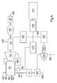
- FIG. 3is a schematic block diagram of a power plant according to the invention with CO 2 sequestration shown.
- the power plantwill be with you as a whole designated by reference numeral 300.
- the concept of the inventionis that the auxiliary turbine 206 in the in FIG. 2 shown power plant 200, is replaced by a variable speed electric drive to achieve a better overall efficiency of the power plant 300 compared to the power plant 200.
- an inverter 301is provided, which can be designed both as a passive or as an active rectifier.
- An active rectifieractually consists of an inverter circuit operating in rectifier mode. Active rectifiers are able to bidirectionally control the active and reactive power independently of each other and are the current topology for variable medium-voltage drives.
- an electric machinefor example, an induction motor 303
- induction motors and synchronous machinesare used in this power range.
- the inventionis not limited to a particular type of electric motor. It is only important that the power output of the electric machine 303 by means of the inverter or inverter 302 is variably controllable.
- the electric machine 303has a rated output of 40 megawatts with a power plant output of 800 MW. More generally, the electric machine 303 has a rated power equivalent to approximately 5% of the rated power of the power plant.
- Electrically driven compressors in this power rangeare used, for example, in liquefied natural gas plants. Such electric drives are commercially available.
- Inverters 301 and 302are configured so that both are capable of converting direct current into alternating current and vice versa.
- Power convertersare used to control the electrical machine.
- Today, power convertersare being modularly built to form so-called Power Electronic Building Blocks (PEBB).
- IGBTsInsulated Gate Bipolar Transistor
- GCTsGate Commutated Thyristors
- GTOsgate turn-off thyristors
- IGBTsIGBTs in converters.
- these voltage convertershave an inner DC bus or a DC bus 304.
- An advantage of this designis that by interconnecting standardized components, different power levels of PEBBs can be inexpensively constructed.
- the electric drive for the compressor 204that is, the inverter 301, the inverter 302 and the electric machine 303 have an efficiency of over 95%.
- the compressor 204is controlled by the inverter which controls the speed of the electric machine 303. In this way, no valve control, for example, using throttle valves on the part of the compressor is required and thereby losses are minimized. An estimate has shown that the compressor system consumes about 6% of the total power of the main turbine's electrical power.
- the DC bus 304 of the electric driveis supplied with a network-side 3-phase electric rectifier with electrical energy, which in the in FIG. 3 illustrated embodiment according to the active power of the compressor drive is dimensioned.
- the inverter 301can provide a very fast VAR control in order to adjust the reactive power very quickly. Namely, this allows the exciter of the generator to design its field winding for slower changes, which reduces its cost.
- the electric drive according to the inventioncan be retrofitted in existing power plants in a simple manner. After an estimation, the overall efficiency becomes The power plant is reduced by the deposition of carbon dioxide from the exhaust gases by about 6% of the rated output power.
- FIG. 4is a schematic block diagram of a second embodiment of a power plant according to the invention with CO 2 -Sequestration shown.
- the power plantis designated as a whole by the reference numeral 400.
- an electrical energy store 401is connected to the DC voltage bus 304.
- the energy storagemay be, for example, lead-acid batteries, which are relatively inexpensive. Sodium-sulfur batteries, which are durable, are also used economically today.
- the energy store 401is connected to the DC bus 304 by means of a DC-DC converter (DC / DC converter) 402.
- the power converter 400 in inverter operation 301may provide black start capabilities to power plant 400 thus equipped.
- a power plantis capable of starting from a standstill without the need for power from a power grid.
- All ancillaries of the power plant 400can be supplied via the DC bus 304, which behaves like an uninterruptible power supply (UPS).
- UPSuninterruptible power supply
- the inventive power plant 400is suitable for island operation because voltage control (VAR control) is possible by using the active rectifier 301 for this purpose.
- energy storage in batteries in the energy storage 401enables a very rapid response to increased power demand in the network.
- the reactioncan be much faster than is possible, for example, in a pumped storage power plant.
- the energy storage 401can deliver a power of at least 5% of the rated power of the power plant during a period of 8 hours. For a 800 megawatt power plant, 5% of the rated output corresponds to 40 megawatts. With a larger number of such energy storage, distributed over a larger number of power plants, it is then also possible to completely shut off power plants that are only willing to completely cover a temporary increased energy demand from the electrical energy storage 401.
- the energy storage devices 401can be installed locally at individual power plants or centrally in a power plant-spanning network.
- a further feature of the inventionis the fact that the primary control function of the generator, which depends on the dimensioning of the network inverter, is shifted to the network-side inverter. Thus, it is possible to completely switch off the generator 105 and thus avoid considerable standby losses.
- the shared medium voltage DC bus 304may supply other inverter supply loads throughout the power plant 400. This includes all pumps and blowers.
- a further inverter 403is provided, which is connected to the DC voltage bus 304.
Landscapes
- Engineering & Computer Science (AREA)
- Chemical & Material Sciences (AREA)
- Mechanical Engineering (AREA)
- General Engineering & Computer Science (AREA)
- Analytical Chemistry (AREA)
- General Chemical & Material Sciences (AREA)
- Oil, Petroleum & Natural Gas (AREA)
- Chemical Kinetics & Catalysis (AREA)
- Combustion & Propulsion (AREA)
- Physics & Mathematics (AREA)
- Thermal Sciences (AREA)
- Control Of Eletrric Generators (AREA)
Description
Translated fromGermanDie Erfindung betrifft ein Kraftwerk, bei dem aus fossilem Brennstoff Elektrizität erzeugt wird, wobei die Kohlendioxidemissionen des Kraftwerkes reduziert sind. Insbesondere betrifft die Erfindung ein Kraftwerk nach Anspruch 1. Weiterhin betrifft die Erfindung ein Energieversorgungssystem, in welchem eine Mehrzahl von erfindungsgemäßen Kraftwerken über ein Stromversorgungsnetz miteinander verbunden ist.The invention relates to a power plant in which electricity is generated from fossil fuel, wherein the carbon dioxide emissions of the power plant are reduced. In particular, the invention relates to a power plant according to claim 1. Furthermore, the invention relates to a power supply system in which a plurality of power plants according to the invention is connected to each other via a power supply network.
Eine der Ursachen für die in den letzten Jahren vermehrt zu beobachtenden klimatischen Veränderungen wird in der Emission von so genannten Treibhausgasen gesehen. Zu der Gruppe der Treibhausgase gehört Kohlendioxid (CO2). Aus dieser Erkenntnis heraus haben viele Nationen das Kyoto-Protokoll ratifiziert, welches im Jahr 2005 in Kraft getreten ist. In diesem Protokoll haben sich viele Industrienationen zu einer schrittweisen Reduzierung ihrer CO2-Emissionen verpflichtet. Ein wesentlicher Ansatzpunkt, um diese Ziele zu erreichen, ist die Reduzierung der CO2-Emission bei der Stromerzeugung. Zu diesem umweltpolitischen Ziel tritt ein handfestes wirtschaftliches Interesse, denn für CO2-Emissionen benötigt der Emittent entsprechende Zertifikate, deren Kosten in Zukunft ansteigen werden.One of the causes of the climatic changes observed in recent years is the emission of so-called greenhouse gases. The group of greenhouse gases includes carbon dioxide (CO2 ). From this realization, many nations have ratified the Kyoto Protocol, which came into force in 2005. In this protocol, many industrialized nations have committed to a gradual reduction in their CO2 emissions. An important starting point for achieving these goals is the reduction of CO2 emissions in power generation. This environmental policy objective has a tangible economic interest, as the issuer requires corresponding certificates for CO2 emissions, the costs of which will rise in the future.
In diesem Umfeld wächst zum einen das Interesse an der Stromerzeugung aus erneuerbaren Energien und zum anderen das Interesse, die CO2-Emissionen von Kraftwerken, in denen fossile Energieträger verfeuert werden, zu reduzieren oder im besten Fall ganz zu unterbinden.On the one hand, there is a growing interest in generating electricity from renewable energies and, on the other, there is an interest in reducing or at best eliminating the CO2 emissions of power plants burning fossil fuels.
In Kraftwerken auf Basis von fossilen Energieträgern, wie zum Beispiel Kohle, werden die Abgase bereits von Mineralien und Staubpartikeln mit elektrostatischen Filtern gereinigt. Um das Kohlendioxid einzufangen, wird aus den gereinigten Abgasen das CO2 abgeschieden und mit einem Kompressor verdichtet, wobei das Kohlendioxid zum Zweck der Speicherung oder des Transportes verflüssigt wird. Im Stand der Technik wird hierzu vorgeschlagen, den Kompressor mit einer Hilfsturbine anzutreiben, die mit Dampf versorgt wird, welcher von der Hauptturbine des Kraftwerkes abgezweigt wird. Nicht nur der Energiebedarf der Hilfsturbine senkt die Gesamteffizienz des Kraftwerkes, sondern schon allein durch die Tatsache, dass der Dampfstrom zu der Hauptturbine geändert wird und die Ventilregelung zur Leistungssteuerung der Hilfsturbine Verluste verursacht, wird die Effizienz des Kraftwerkes reduziert. Als eine Abschätzung kann gelten, dass 12% der Leistung des Kraftwerkes bei diesem Ansatz verloren gehen. Der Grund dafür ist, dass eine Dampfturbine so optimiert ist, dass sie bei ihrer Nennleistung mit einer festgelegten Drehzahl und einer festgelegten Frequenz und Spannung des Generators die höchstmögliche Effizienz aufweist. Abweichungen von diesen optimalen Nennwerteinstellungen reduzieren den Wirkungsgrad der Hauptturbine. Die Effizienz der Hauptturbine wird weiterhin vermindert, weil alle Neben- und Hilfsaggregate mit ihrer Nennleistung weiterlaufen, die für eine höhere Leistung der Hauptturbine ausgelegt sind. Bei der Auslegung der Nebenaggregate ist nämlich die Leistungsminderung der Hauptturbine durch den Anschluss der Hilfsturbine nicht berücksichtigt. In der Regel bedeutet das, dass die Neben- und Hilfsaggregate mehr Energie verbrauchen als eigentlich notwendig wäre. Dies zusammengenommen führt zu einer Abschätzung, wonach bei der CO2-Verflüssigung mithilfe eines Kompressors, der von einer Hilfsturbine angetrieben wird, ungefähr 12% der Leistung der Hauptturbine verbraucht werden. Ein solcher Ansatz ist zum Beispiel aus der
Darüber hinaus erfordert die Ableitung von überkritischem Dampf aus der Hauptturbine konstruktive Maßnahmen, die teuer und schwer durchzuführen sind. Aus diesen Gründen ist die Nachrüstung von schon bestehenden Kraftwerken mit diesem Konzept nicht praktikabel.In addition, the discharge of supercritical steam from the main turbine requires design measures that are expensive and difficult to perform. For these reasons, the retrofitting of existing power plants with this concept is impractical.
Ein weiterer Aspekt der bekannten Kraftwerke ist, dass diese großen Einheiten nicht schnell starten können und nicht in der Lage sind, einen Schwarzstart durchzuführen, weil keine Energiespeicher zur Verfügung stehen, um die Hilfs- und Nebenaggregate wie Pumpen, Steuerungen und Gebläse mit Energie zu versorgen. Unter Schwarzstart versteht der Fachmann, dass ein Kraftwerk in der Lage ist, aus dem Stillstand heraus anzufahren, ohne hierfür Energie aus einem Stromversorgungsnetz zu benötigen. Außerdem ist ein Inselbetrieb nicht möglich, weil eine Frequenzregelung nicht für jedes Kraftwerk zur Verfügung steht. Eine Regelung mit der primären Leistung, mit dem Ziel, eine geringere Leistung abzugeben, ist sehr ineffizient, weil der Dampfkessel unter vollem Dampfdruck gehalten werden muss, so dass die Leistung schnell hochgefahren werden kann, wenn eine Leistungsschwankung auftritt.Another aspect of the known power plants is that these large units can not start quickly and are unable to perform a black start because there are no energy stores available to power the ancillaries such as pumps, controls and blowers , By black start, it is understood by those skilled in the art that a power plant is capable of starting from a standstill without the need for power from a power grid. In addition, isolated operation is not possible because frequency control is not available for every power plant. A primary power control aiming at lower power output is very inefficient because the steam boiler must be kept at full steam pressure so that power can be ramped up quickly when power fluctuation occurs.
Hiervon ausgehend besteht ein Bedarf für Kraftwerke, die fossile Brennstoffe als Primärenergieträger verbrennen, die aber weniger CO2 als herkömmliche Kraftwerke in die Atmosphäre ausstoßen, insbesondere im Teillastbetrieb. Im Idealfall sollte ein Kraftwerk trotz des Einsatzes von fossilen Energieträgern kein CO2 in die Atmosphäre entweichen lassen. In diesem Fall spricht man auch von einem Nullemissionskraftwerk oder einem emissionsfreien Kraftwerk, obschon andere Verbrennungsgase als CO2 wie zum Beispiel Stickoxide (NOx) weiterhin in die Atmosphäre entweichen.On this basis, there is a need for power plants that burn fossil fuels as primary energy sources, but which emit less CO2 than conventional power plants in the atmosphere, especially in part-load operation. Ideally, a power plant should not release CO2 into the atmosphere despite the use of fossil fuels. In this case, one also speaks of a zero-emission power plant or an emission-free power plant, although other combustion gases than CO2 such as nitrogen oxides (NOx) continue to escape into the atmosphere.
Zur Lösung dieser Aufgabe schlägt die Erfindung ein Kraftwerk vor, bei dem ein fossiler Brennstoff zur Stromerzeugung eingesetzt wird. Eine Turbine treibt einen Generator an, der elektrischen Strom erzeugt. Das Kraftwerk weist eine Abscheideeinrichtung auf, mit welcher Kohlendioxid aus dem Abgas des Kraftwerkes abgeschieden wird. Das Kraftwerk weist weiterhin einen Kompressor auf, mit welchem das abgeschiedene Kohlendioxid verflüssigt wird. Die Erfindung zeichnet sich dadurch aus, dass der Kompressor mit einem elektrischen Antrieb gekoppelt ist. Des Weiteren ist ein Umrichter an das Wechselspannungs-Mittelspannungsnetz angeschlossen, um Gleichstrom zu erzeugen, der von einem Inverter in eine Wechselspannung umgewandelt wird, um den elektrischen Antrieb des Kompressors mit Energie zu versorgen. Der Umrichter und der Inverter sind über ein Gleichstrom-Mittelspannungsnetz miteinander verbunden. In dieses Gleichstrom-Mittelspannungsnetz lassen sich mit relativ geringem Aufwand regenerative Energiequellen und elektrische Energiespeicher integrieren. Bei den regenerativen Energiequellen kommen insbesondere Windparks in Frage. Der Umrichter kann ein aktiver Gleichrichter sein, der auch Blindleistung (Grundschwingungsblindleistung und harmonische) kompensieren kann.
Ein Vorteil des erfindungsgemäßen Kraftwerkes ist, dass weniger Primärenergie verbraucht wird, um das Kohlendioxid aus den Abgasen abzuscheiden und zu verflüssigen als bei Anlagen, wie sie aus dem Stand der Technik bekannt sind.To solve this problem, the invention proposes a power plant in which a fossil fuel is used to generate electricity. A turbine drives a generator that generates electricity. The power plant has a separator, with which carbon dioxide from the exhaust of the power plant is deposited. The power plant also has a compressor with which the separated carbon dioxide is liquefied. The invention is characterized in that the compressor is coupled to an electric drive. Furthermore, an inverter is connected to the AC medium voltage network to generate DC power, which is converted by an inverter into an AC voltage to power the electric drive of the compressor. The inverter and the inverter are connected via a DC medium-voltage network. In this DC medium-voltage network can be integrated with relatively little effort regenerative energy sources and electrical energy storage. In the case of regenerative energy sources, in particular wind farms come into question. The inverter can be an active rectifier that can also compensate reactive power (fundamental reactive power and harmonic).
An advantage of the power plant according to the invention is that less primary energy is consumed to separate the carbon dioxide from the exhaust gases and liquefy than systems known in the prior art.
Bei einem Ausführungsbeispiel der Erfindung kann die Turbine eine Dampfturbine sein, wobei das Kraftwerk einen Kessel umfasst, in welchem der fossile Brennstoff verbrannt wird, um Dampf für die Turbine zu erzeugen, die den Generator antreibt.In one embodiment of the invention, the turbine may be a steam turbine, wherein the power plant includes a boiler in which the fossil fuel is burned to generate steam for the turbine that drives the generator.
Bei einer zweckmäßigen Ausführungsform der Erfindung gibt der Generator den erzeugten elektrischen Strom an ein Wechselspannungs-Mittelspannungsnetz ab. In diesem Fall ist es vorteilhaft, wenn der elektrische Antrieb des Kompressors zur Versorgung mit elektrischer Energie an das Wechselspannungs-Mittelspannungsnetz angeschlossen ist.In an expedient embodiment of the invention, the generator outputs the generated electric current to an AC medium-voltage network. In this case, it is advantageous if the electric drive of the compressor is connected to the supply of electrical energy to the AC medium-voltage network.
Mit Vorteil lässt der elektrische Antrieb des Kompressors variable Drehzahlen zu, was sich günstig auf dem Wirkungsgrad des Kraftwerkes auswirkt, weil der Kompressor auf diese Weise effizient an den tatsächlichen Betriebszustand des Kraftwerkes anpassbar ist.Advantageously, the electric drive of the compressor to variable speeds, which has a favorable effect on the efficiency of the power plant, because the compressor is in this way efficiently adaptable to the actual operating state of the power plant.
Vorteilhafterweise kann an das Gleichstrom-Mittelspannungsnetz ein weiterer Inverter angeschlossen sein, der elektrische Nebenaggregate des Kraftwerkes mit Energie versorgt. In diesem Fall ist es besonders vorteilhaft, wenn die Nebenaggregate elektrische Antriebe mit variabler Drehzahl aufweisen, denn so können weitere Effizienzvorteile hinsichtlich des Eigenenergiebedarfs des Kraftwerkes realisiert werden, insbesondere im Teillastbereich.Advantageously, can be connected to the DC medium-voltage network, a further inverter, the electrical ancillaries of the power plant with Energy supplied. In this case, it is particularly advantageous if the ancillary units have variable-speed electrical drives, because then further efficiency advantages with regard to the own energy demand of the power plant can be realized, in particular in the partial load range.
Bei einem weiteren vorteilhaften Ausführungsbeispiel der Erfindung ist das Kraftwerk mit einem elektrischen Energiespeicher verbunden. Der Energiespeicher kann kurzfristige Schwankungen des Energiebedarfs in einem Versorgungsnetz schnell ausgleichen und verleiht dem Kraftwerk darüber hinaus Schwarzstartfähigkeiten.In a further advantageous embodiment of the invention, the power plant is connected to an electrical energy store. The energy storage device can quickly compensate for short-term fluctuations in energy demand in a utility grid and also gives the power plant black-start capabilities.
Es hat sich als zweckmäßig erwiesen, wenn der Energiespeicher aus einer elektrischen Batterie oder aus einer Mehrzahl von miteinander verbundenen elektrischen Batterien aufgebaut ist. Hierfür kommen unter anderem Bleibatterien in Frage, die kostengünstig und langlebig sind.It has proved to be expedient if the energy store is constructed from an electric battery or from a plurality of interconnected electric batteries. Lead-acid batteries, which are inexpensive and durable, are suitable for this purpose.
Der Energiespeicher kann sowohl innerhalb als auch außerhalb des Kraftwerkes aufgestellt sein. Dabei ist es auch möglich, dass ein einzelner Energiespeicher als Energiespeicher für mehrere Kraftwerke dient. Grundsätzlich sind hierbei auch Mischformen möglich, so dass eine große Flexibilität bei der Gestaltung des Energiespeichers vorhanden ist, um ihn an die jeweils herrschenden Bedingungen anpassen zu können.The energy storage can be installed both inside and outside the power plant. It is also possible that a single energy storage is used as energy storage for multiple power plants. In principle, mixed forms are also possible in this case, so that there is great flexibility in the design of the energy store in order to be able to adapt it to the respectively prevailing conditions.
Es hat sich als vorteilhaft erwiesen, wenn der Energiespeicher an das Gleichstrom Mittelspannungsnetz des Kraftwerkes angeschlossen ist.It has proven to be advantageous if the energy storage is connected to the DC medium-voltage network of the power plant.
Um die Betriebsspannung des Energiespeichers an die Betriebsspannung des Gleichstrom Mittelspannungsnetzes anzupassen, ist es zweckmäßig, wenn der Energiespeicher über einen Gleichspannungswandler an das Gleichstrom/Mittelspannungsnetz des Kraftwerkes angeschlossen ist.In order to adapt the operating voltage of the energy storage to the operating voltage of the DC medium-voltage network, it is expedient if the energy storage is connected via a DC-DC converter to the DC / medium voltage network of the power plant.
Bei einem Ausführungsbeispiel des erfindungsgemäßen Kraftwerkes ist eine Windkraftanlage an das Gleichstrom-Mittelspannungsnetz angeschlossen. Auf diese Weise ist es besonders einfach möglich, die schwankende Energieabgabe eines Windkraftwerkes in ein Elektrizitätsversorgungsnetz zu integrieren.In one embodiment of the power plant according to the invention, a wind turbine is connected to the DC medium-voltage network. To this Way, it is particularly easy to integrate the fluctuating energy output of a wind power plant in an electricity supply network.
Gemäß einem zweiten Aspekt der Erfindung wird ein Energieversorgungssystem aus einer Anzahl von erfindungsgemäßen Kraftwerken vorgeschlagen, die in einem Stromversorgungsnetz miteinander verbunden sind. Dabei ist es vorgesehen, dass mehrere der Kraftwerke jeweils einen Energiespeicher aufweisen. Ein Vorteil des erfindungsgemäßen Energieversorgungssystems ist, dass Lastschwankungen in dem Stromversorgungsnetz aus den Energiespeichern ausgeglichen werden können, ohne dass ein Kraftwerk im Bereitschaftsbetrieb gehalten werden muss, wie es derzeit der Fall ist. Allein dadurch können schon erhebliche Mengen CO2 gespart werden, ohne Berücksichtigung einer möglichen CO2 Sequestrierung.According to a second aspect of the invention, a power supply system is proposed from a number of power plants according to the invention, which are interconnected in a power supply network. It is envisaged that several of the power plants each have an energy storage. An advantage of the energy supply system according to the invention is that load fluctuations in the power supply network can be compensated from the energy stores without having to keep a power plant in standby mode, as is currently the case. This alone can save considerable amounts of CO2 , without consideration of a possible CO2 sequestration.
In der Zeichnung sind herkömmliche Kraftwerke sowie zwei Ausführungsbeispiele der Erfindung dargestellt. In den Figuren sind gleiche oder einander entsprechende Elemente mit demselben Bezugszeichen versehen. Es zeigen:
- Fig.1
- ein Blockdiagramm eines herkömmlichen Kraftwerkes ohne Kohlendioxidsequestrierung;
- Fig.2
- ein Blockdiagramm eines herkömmlichen Kraftwerkes mit Kohlendioxidsequestrierung;
- Fig.3
- ein Blockdiagramm eines ersten Ausführungsbeispiels eines erfindungsgemäßen Kraftwerkes mit Kohlendioxidsequestrierung; und
- Fig. 4
- ein Blockdiagramm eines zweiten Ausführungsbeispiels eines erfindungsgemäßen Kraftwerkes mit Kohlendioxidsequestrierung.
- Fig.1
- a block diagram of a conventional power plant without carbon dioxide sequestration;
- Fig.2
- a block diagram of a conventional power plant with carbon dioxide sequestration;
- Figure 3
- a block diagram of a first embodiment of a power plant according to the invention with carbon dioxide sequestration; and
- Fig. 4
- a block diagram of a second embodiment of a power plant according to the invention with carbon dioxide sequestration.
In
In dem Kraftwerk ist weiterhin ein Kondensor 109 vorgesehen, der mit einem Kühlkreis Dampf in Wasser wandelt. Über eine Pumpe 110 wird Wasser im Kessel eingespeist. Als Beispiel für ein solches Nebenaggregat ist in
In
Die Verbrennungsabgase treten aus dem elektrostatischen Filter 112 gereinigt aus und werden z. B. einem Wäscher 201 zugeführt, der als Abscheideeinrichtung für CO2 dient. In dem Wäscher 201 wird das gasförmige CO2 an eine CO2-absorbierende Flüssigkeit bei einer ersten Temperatur angelagert und anschließend aus der absorbierenden Flüssigkeit bei einer höheren Temperatur wieder ausgetrieben, wonach das CO2 in reiner Form vorliegt. Bei der absorbierenden Flüssigkeit kann es sich beispielsweise um ein Amin handeln, an welches sich Kohlendioxid bei 27° Celsius anlagert und bei 150° Celsius wieder abgegeben wird. Derartige Anlagen sind im Stand der Technik bekannt und werden deshalb nicht im Einzelnen beschrieben, weil es bei der vorliegenden Erfindung nicht darauf ankommt, auf welche Weise das CO2-Gas abgeschieden wird. Bei Kohlekraftwerken macht das CO2 einen Anteil von ungefähr 15% des von der Verbrennung freigesetzten Rauchgases aus. Die von den CO2 befreiten anderen Gasanteile verlassen den Wäscher 201 durch einen Kamin 202 und werden in die Atmosphäre entlassen. Das gasförmige CO2 wird über eine Leitung 203 einem Kompressor 204 zugeführt, wo es soweit verdichtet wird, dass es in die flüssige Phase übergeht. Der Kompressor 204 stellt somit an einer Ausgangsleitung 205 flüssiges CO2 zur Verfügung, von wo aus es zum Beispiel über eine Pipeline oder mithilfe von Transportbehältern zur endgültigen Sequestrierung abtransportiert wird.The combustion exhaust gases exit from the
Bei dem in
Aus heutiger Sicht ist dieser Ansatz nicht optimal, weil bei dieser Konstruktion ungefähr 12% der Leistung der Hauptturbine 102 verloren gehen. Die Gründe hierfür wurden bereits eingangs genannt. Einer der wichtigsten Gründe ist, dass alleine schon die Abzweigung des Dampfes von der Hauptturbine zu einer Reduzierung deren Effizienz führt. Bei der Steuerung über ein Drosselventil 208 treten Enthalpieverluste auf, wodurch der Wirkungsgrad weiter verschlechtert wird.From today's perspective, this approach is not optimal, because in this construction, about 12% of the power of the
In
Zur Ansteuerung der elektrischen Maschine werden Leistungsumrichter benutzt. Heute werden Leistungsumrichter modular aufgebaut, um so genannte Leistungselektronikblöcke (englisch: "Power Electronic Building Blocks", PEBB) zu bilden. IGBT's (Insulated Gate Bipolar Transistor) oder GCT's (Gate Commutated Thyristors) werden in Reihen- oder Parallelschaltungen verwendet, um Spannungskonverter aufzubauen, die Leistungsgrößen über 40 Megawatt erreichen.Power converters are used to control the electrical machine. Today, power converters are being modularly built to form so-called Power Electronic Building Blocks (PEBB). IGBTs (Insulated Gate Bipolar Transistor) or GCTs (Gate Commutated Thyristors) are used in series or parallel circuits to build voltage converters that achieve power ratings over 40 megawatts.
Es ist bekannt, beispielsweise in Umrichtern Hochleistungsschalter in Form von GTOs (Gate Turn-off Thyristors) oder GCTs sowie IGBT's einzusetzen. Diese Halbleiterbauelemente werden durch einen Gatestromimpuls eingeschaltet. Zum Ausschalten der Bauelemente wird im Falle des GTO ein Teil des Anodenstroms, im Falle des GCT sogar der gesamte Anodenstrom, über das Gate aus dem Halbleiter herausgeführt.It is known, for example, to use high-performance switches in the form of gate turn-off thyristors (GTOs) or GCTs and IGBTs in converters. These semiconductor devices are turned on by a gate current pulse. In the case of the GTO, part of the anode current, in the case of the GCT even the entire anode current, is led out of the semiconductor via the gate in order to switch off the components.
Im Ergebnis haben diese Spannungskonverter einen inneren Gleichspannungsbus oder ein Gleichspannungsnetzwerk 304. Ein Vorteil dieser Konzeption ist, dass durch Zusammenschaltung von standardisierten Bauteilen unterschiedliche Leistungsstufen der PEBBs kostengünstig aufgebaut werden können.As a result, these voltage converters have an inner DC bus or a
Der elektrische Antrieb für den Kompressor 204, das heißt, der Umrichter 301, der Inverter 302 und die elektrische Maschine 303 haben eine Effizienz von über 95%. Der Kompressor 204 wird von dem Inverter gesteuert, welcher die Drehzahl, beziehungsweise Leistung der elektrischen Maschine 303 steuert. Auf diese Weise wird keine Ventilsteuerung, zum Beispiel mithilfe von Drosselventilen auf Seiten des Kompressors benötigt und dadurch werden Verluste minimiert. Eine Abschätzung hat gezeigt, dass das Kompressorsystem ungefähr 6% der Gesamtleistung der von der Hauptturbine erzeugten elektrischen Leistung verbraucht. Der Gleichspannungsbus 304 des elektrischen Antriebes wird mit einem netzseitigen 3-Phasen elektrischen Gleichrichter mit elektrischer Energie versorgt, der bei dem in
Darüber hinaus ist es bekannt, dass der Umrichter 301 eine sehr schnelle VAR-Steuerung zur Verfügung stellen kann, um die Blindleistung sehr schnell anpassen zu können. Dies gestattet es dem Erreger des Generators nämlich, dessen Feldwicklung für langsamere Änderungen auszugestalten, was dessen Kosten reduziert.In addition, it is known that the
Der erfindungsgemäße elektrische Antrieb kann auf einfache Weise in bestehenden Kraftwerken nachgerüstet werden. Nach einer Abschätzung wird die Gesamteffizienz des Kraftwerkes durch die Abscheidung des Kohlendioxids aus den Abgasen um ungefähr 6% der Ausgangsnennleistung vermindert.The electric drive according to the invention can be retrofitted in existing power plants in a simple manner. After an estimation, the overall efficiency becomes The power plant is reduced by the deposition of carbon dioxide from the exhaust gases by about 6% of the rated output power.
In
Unter Schwarzstart versteht der Fachmann, dass ein Kraftwerk in der Lage ist, aus dem Stillstand heraus anzufahren, ohne hierfür Energie aus einem Stromversorgungsnetz zu benötigen. Alle Nebenaggregate des Kraftwerkes 400 können über den Gleichspannungsbus 304 versorgt werden, der sich wie eine unterbrechungsfreie Stromversorgung verhält (Englisch: Uninterruptable Power Supply, UPS). Somit ist das erfindungsgemäße Kraftwerk 400 zum Inselbetrieb geeignet, weil eine Spannungsteuerung (VAR-Control) möglich ist, indem der aktive Gleichrichter 301 für diesen Zweck eingesetzt wird.By black start, it is understood by those skilled in the art that a power plant is capable of starting from a standstill without the need for power from a power grid. All ancillaries of the
Darüber hinaus ermöglicht die Energiespeicherung in Batterien in dem Energiespeicher 401 eine sehr rasche Reaktion auf eine erhöhte Leistungsanforderung im Netz. Die Reaktion kann sehr viel schneller erfolgen als es beispielsweise bei einem Pumpspeicherkraftwerk möglich ist.In addition, energy storage in batteries in the
Es ist vorgesehen, dass der Energiespeicher 401 eine Leistung von mindestens 5% der Nennleistung des Kraftwerkes während einer Zeitdauer von 8 Stunden abgeben kann. Bei einem 800 Megawatt Kraftwerk entsprechen 5% der Nennleistung 40 Megawatt. Bei einer größeren Anzahl derartiger Energiespeicher, verteilt über eine größere Anzahl von Kraftwerken, ist es dann auch möglich, Kraftwerke, die lediglich in Bereitschaft stehen, vollständig abzuschalten und einen zeitweiligen erhöhten Energiebedarf allein aus den elektrischen Energiespeichern 401 zu decken. Die Energiespeicher 401 können dezentral jeweils bei einzelnen Kraftwerken aufgestellt sein oder zentral in einem kraftwerksübergreifenden Netz.It is envisaged that the
Es dauert ungefähr eine Stunde, um ein stillstehendes Kraftwerk mit kaltem Kessel auf seine Nennleistung hochzufahren. Mithilfe der elektrischen Energiespeicher 401 ist es ohne weiteres möglich, diese Zeitdauer zu überbrücken. Allein dieser Umstand, dass ein Kraftwerk vollständig abgeschaltet wird und nicht im Bereitschaftsbetrieb weiterläuft, führt bereits ohne CO2-Sequestrierung gegenüber der heutigen Technologie zu einer erheblichen Einsparung von CO2-Emissionen bei der Stromerzeugung.It takes about an hour to raise a cold-boiler stationary power plant to its rated capacity. By means of the
Ein weiteres Merkmal der Erfindung ist die Tatsache, dass die Primärsteuerungsfunktion des Generators, die von der Dimensionierung des Netzinverters abhängt, zu dem netzseitigen Inverter zu verschieben. Somit ist es möglich, den Generator 105 vollständig abzuschalten und damit erhebliche Bereitschaftsverluste zu vermeiden. Von dem gemeinsamen Mittelspannungs - Gleichspannungsbus 304 können andere Inverterversorgungslasten in dem gesamten Kraftwerk 400 versorgt werden. Dazu gehören alle Pumpen und Gebläse. Zu diesem Zweck ist ein weiterer Inverter 403 vorgesehen, der an dem Gleichspannungsbus 304 angeschlossen ist. Dieser Aufbau des Kraftwerkes 400 ermöglicht es, dass im Teillastbetrieb und während des Anfahrens des Kraftwerkes das Kraftwerk flexibler gesteuert werden kann, welches die Effizienz und die Dynamik in dem Sinne verbessert, als ein schnelleres Anfahren erzielt wird.A further feature of the invention is the fact that the primary control function of the generator, which depends on the dimensioning of the network inverter, is shifted to the network-side inverter. Thus, it is possible to completely switch off the
Durch die Verwendung von Mittelspannungs-Gleichspannungskabeln, welche in
Für Windfarmen ist der Einsatz von Gleichstromnetzen zum Sammeln und zur Weiterleitung der von einer Vielzahl von Windturbinen erzeugten elektrischen Energie bereits in zahlreichen Publikationen vorgeschlagen worden, wie zum Beispiel von
Da der netzseitige Inverter eine hohe Bandbreite von mehreren Kilohertz hat, können harmonische und subharmonische Schwingungen ohne zusätzliche Filterschaltungen kompensiert werden, indem Leistung aus den Batterien gezogen wird.Since the line side inverter has a high bandwidth of several kilohertz, harmonic and subharmonic oscillations can be compensated without additional filter circuits by pulling power from the batteries.
Die Erfindung ist zwar im Zusammenhang mit einem Kraftwerk beschrieben worden, bei dem fossile Brennstoffe in einem Kessel 101 verbrannt werden, um Dampf für eine Dampfturbine zu erzeugen. Dennoch ist die Erfindung grundsätzlich auch auf Kraftwerke anwendbar, bei denen Erdgas in Gasturbinen verbrannt wird.While the invention has been described in the context of a power plant where fossil fuels are burned in a
Claims (16)
- A power plant in which a fossil fuel is used to generate power, whereby a turbine (102) drives a generator (105) generates electricity, whereby the power plant has a separator (201) with which carbon dioxide is separated out of the exhaust gas of the power plant, and whereby the power plant also has a compressor (204) with which the separated carbon dioxide is liquefied, the compressor (204) is coupled to an electric drive (303),characterized in that the generator (105) supplies the generated electricity to an alternating-voltage medium-voltage network (106),in that a converter (301) is connected to the alternating-voltage medium-voltage network (106) in order to generate direct current that is converted by an inverter (302) into an alternating voltage for purposes of supplying the electric drive (303) of the compressor (204) with energy, and the electric machine (303) has a rated output that is approximately 5% of the rated output of the power plant.
- The power plant according to Claim 1,characterized in that the turbine is a steam turbine, andin that the power plant comprises a boiler (101) in which fossil fuel is burned in order to generate steam for the turbine (102) that drives the generator.
- The power plant according to one or more of the preceding claims,characterized in that the electric drive (303) of the compressor (204) is connected to the alternating-voltage medium-voltage network (106) in order to obtain its electric power.
- The power plant according to claim 1,characterized in that the electric drive (303) of the compressor (204) allows variable speeds.
- The power plant according to Claim 1,characterized in that the converter (301) is an active rectifier.
- The power plant according to Claim 1,characterized in that the converter (301) and the inverter (302) are connected to each other via a direct-current medium-voltage network (304).
- The power plant according to Claim 5,characterized in that another inverter (403) is connected to the direct-current medium-voltage network (304), and it can supply power to secondary electric aggregates (110) of the power plant.
- The power plant according to Claim 7,characterized in that the secondary aggregates (110) have electric drives with variable speeds.
- The power plant according to one or more of the preceding claims,characterized in that the power plant is connected to an electric energy storage device (401).
- The power plant according to Claim 9,characterized in that the energy storage device (401) consists of an electric battery or of a plurality of electric batteries that are connected to each other.
- The power plant according to Claim 10,characterized in that the energy storage device (401) is set up outside of the power plant.
- The power plant according to Claim 11,characterized in that a single energy storage device (401) serves as the energy storage device for several power plants.
- The power plant according to Claim 10,characterized in that the energy storage device (401) is connected to the direct-current medium-voltage network (304) of the power plant.
- The power plant according to Claim 9,characterized in that the energy storage device (401) is connected via a direct-voltage converter (402) to the direct-current medium-voltage network (304) of the power plant.
- The power plant according to one or more of the preceding claims,characterized in that a wind power plant is connected to the direct-current medium-voltage network (304).
- An energy supply system comprising several power plants according to one or more of the preceding claims that are connected to each other via a power supply grid, whereby several of the power plants have an energy storage device (401).
Applications Claiming Priority (2)
| Application Number | Priority Date | Filing Date | Title |
|---|---|---|---|
| DE200810039449DE102008039449A1 (en) | 2008-08-25 | 2008-08-25 | Emission-free Karftwerk |
| PCT/EP2009/005872WO2010025813A2 (en) | 2008-08-25 | 2009-08-13 | Zero-emission power plant |
Publications (2)
| Publication Number | Publication Date |
|---|---|
| EP2373401A2 EP2373401A2 (en) | 2011-10-12 |
| EP2373401B1true EP2373401B1 (en) | 2013-06-19 |
Family
ID=41605660
Family Applications (1)
| Application Number | Title | Priority Date | Filing Date |
|---|---|---|---|
| EP09777855.9ANot-in-forceEP2373401B1 (en) | 2008-08-25 | 2009-08-13 | Zero-emission power plant |
Country Status (5)
| Country | Link |
|---|---|
| US (1) | US20110148123A1 (en) |
| EP (1) | EP2373401B1 (en) |
| JP (1) | JP5635510B2 (en) |
| DE (1) | DE102008039449A1 (en) |
| WO (1) | WO2010025813A2 (en) |
Families Citing this family (11)
| Publication number | Priority date | Publication date | Assignee | Title |
|---|---|---|---|---|
| EP2395205A1 (en)* | 2010-06-10 | 2011-12-14 | Alstom Technology Ltd | Power Plant with CO2 Capture and Compression |
| DE102011086374A1 (en)* | 2011-11-15 | 2013-05-16 | Siemens Aktiengesellschaft | High-temperature energy storage with recuperator |
| DE102012204210A1 (en) | 2012-03-16 | 2013-09-19 | Siemens Aktiengesellschaft | Steam power plant integrated high-temperature battery |
| US9803803B1 (en) | 2014-06-20 | 2017-10-31 | Northwest Natural Gas Company | System for compressed gas energy storage |
| CN107269333A (en)* | 2017-04-21 | 2017-10-20 | 华电电力科学研究院 | One kind coupling IGCC and CO2The zero carbon polygenerations systeme and method of conversion |
| EP3647553B1 (en)* | 2018-11-05 | 2022-12-28 | Orcan Energy AG | Supply of an electromechanical power converter with electrical energy from a thermodynamic cyclical process |
| JP7669362B2 (en)* | 2019-12-16 | 2025-04-28 | ゼネラル エレクトリック テクノロジー ゲゼルシャフト ミット ベシュレンクテル ハフツング | SYSTEM AND METHOD FOR MAINTAINING POWER CONTINUITY IN A STEAM-BASED POWER PLANT - Patent application |
| CN112290656B (en)* | 2020-11-23 | 2025-06-13 | 西安热工研究院有限公司 | Supercritical CO2 solar power generation system and method combining hydrogen production, energy storage and fuel cell technology |
| US11484827B2 (en)* | 2021-03-24 | 2022-11-01 | Next Carbon Solutions, Llc | Carbon dioxide sequestration in natural gas pipelines |
| CN113644653B (en)* | 2021-08-20 | 2023-08-01 | 西安交通大学 | Black start path recovery method of power system based on cooperation of new energy and energy storage |
| CN114865696B (en)* | 2022-04-25 | 2023-06-02 | 电子科技大学 | Online scheduling method of hybrid energy system based on SAC algorithm |
Family Cites Families (28)
| Publication number | Priority date | Publication date | Assignee | Title |
|---|---|---|---|---|
| DE1907176A1 (en)* | 1969-02-13 | 1970-09-03 | Siemens Ag | Emergency power supply for nuclear power - stations |
| GB2111602B (en)* | 1981-12-18 | 1985-05-30 | Gen Electric | Combined cycle apparatus for synthesis gas production |
| ES2003265A6 (en)* | 1987-04-21 | 1988-10-16 | Espan Carburos Metal | Method for obtaining CO2 and N2 from internal combustion engine or turbine generated gases |
| US4942734A (en)* | 1989-03-20 | 1990-07-24 | Kryos Energy Inc. | Cogeneration of electricity and liquid carbon dioxide by combustion of methane-rich gas |
| JP2544554B2 (en)* | 1991-10-09 | 1996-10-16 | 関西電力株式会社 | Method for removing CO2 in combustion exhaust gas |
| US5185541A (en)* | 1991-12-02 | 1993-02-09 | 21St Century Power & Light Corporation | Gas turbine for converting fuel to electrical and mechanical energy |
| JP2792777B2 (en) | 1992-01-17 | 1998-09-03 | 関西電力株式会社 | Method for removing carbon dioxide from flue gas |
| NO180520C (en)* | 1994-02-15 | 1997-05-07 | Kvaerner Asa | Method of Removing Carbon Dioxide from Combustion Gases |
| JP3563143B2 (en)* | 1995-02-14 | 2004-09-08 | 千代田化工建設株式会社 | Compressor drive of natural gas liquefaction plant |
| DE69738474T2 (en)* | 1997-09-22 | 2009-01-15 | Clean Energy Systems, Inc., Rancho Cordova | PURE AIR MOTORS FOR TRANSPORT AND OTHER MOTORIZED APPLICATIONS |
| DE69816660T2 (en)* | 1997-12-20 | 2004-05-13 | Alliedsignal Inc. | CONTROL DEVICE FOR MICROTURBINE WITH CONSTANT TURBINE INLET TEMPERATURE |
| US6066898A (en)* | 1998-08-14 | 2000-05-23 | Alliedsignal Inc. | Microturbine power generating system including variable-speed gas compressor |
| US6256994B1 (en)* | 1999-06-04 | 2001-07-10 | Air Products And Chemicals, Inc. | Operation of an air separation process with a combustion engine for the production of atmospheric gas products and electric power |
| AU6638400A (en)* | 1999-08-16 | 2001-03-13 | Coleman Powermate, Inc. | System that supplies electrical power and compressed air |
| DE19940465A1 (en)* | 1999-08-26 | 2001-04-12 | Gesalfina Ag | Combined heat, power and cooling process and power plant equipment to carry out the process |
| DE10236326A1 (en)* | 2001-08-17 | 2003-03-06 | Alstom Switzerland Ltd | Gas storage power station, has power consumption device with static frequency generator that consumes electric power from generator and provides it to additional load |
| JP4003553B2 (en)* | 2002-06-26 | 2007-11-07 | Jfeスチール株式会社 | Power generation method and power generation facility using by-product gas |
| US7762082B1 (en)* | 2003-09-25 | 2010-07-27 | IES Consulting Inc. | Apparatus and method of recovering vapors |
| JP4303152B2 (en)* | 2004-03-22 | 2009-07-29 | 株式会社日立製作所 | Power generation system and control method thereof |
| KR101070906B1 (en)* | 2004-10-01 | 2011-10-06 | 설승기 | Distributed power generation system and control method for the same |
| RU2378519C2 (en)* | 2005-04-05 | 2010-01-10 | Саргас Ас | Thermal electric power station with reduced co2-content and method to produce electric power from coal fuel |
| US20070100506A1 (en)* | 2005-10-31 | 2007-05-03 | Ralph Teichmann | System and method for controlling power flow of electric power generation system |
| US20070235383A1 (en)* | 2006-03-28 | 2007-10-11 | Hans-Joachim Krokoszinski | Hybrid water desalination system and method of operation |
| EP2010755A4 (en)* | 2006-04-21 | 2016-02-24 | Shell Int Research | HEATING SEQUENCE OF MULTIPLE LAYERS IN A FORMATION CONTAINING HYDROCARBONS |
| US8171732B2 (en)* | 2006-09-08 | 2012-05-08 | General Electric Company | Turbocharger for a vehicle with a coanda device |
| NO326634B1 (en)* | 2006-09-12 | 2009-01-26 | Aker Engineering & Technology | Method and system for starting and operating an electrically driven load |
| GB0624599D0 (en)* | 2006-12-09 | 2007-01-17 | Aeristech Ltd | Engine induction system |
| US8225900B2 (en)* | 2008-04-26 | 2012-07-24 | Domes Timothy J | Pneumatic mechanical power source |
- 2008
- 2008-08-25DEDE200810039449patent/DE102008039449A1/ennot_activeWithdrawn
- 2009
- 2009-08-13USUS13/060,955patent/US20110148123A1/ennot_activeAbandoned
- 2009-08-13JPJP2011524226Apatent/JP5635510B2/ennot_activeExpired - Fee Related
- 2009-08-13WOPCT/EP2009/005872patent/WO2010025813A2/enactiveApplication Filing
- 2009-08-13EPEP09777855.9Apatent/EP2373401B1/ennot_activeNot-in-force
Also Published As
| Publication number | Publication date |
|---|---|
| JP2012500928A (en) | 2012-01-12 |
| WO2010025813A2 (en) | 2010-03-11 |
| JP5635510B2 (en) | 2014-12-03 |
| US20110148123A1 (en) | 2011-06-23 |
| WO2010025813A3 (en) | 2011-09-29 |
| DE102008039449A1 (en) | 2010-03-04 |
| EP2373401A2 (en) | 2011-10-12 |
Similar Documents
| Publication | Publication Date | Title |
|---|---|---|
| EP2373401B1 (en) | Zero-emission power plant | |
| EP1485978B1 (en) | Separate network and method for operating a separate network | |
| EP1323222B1 (en) | Island network and method for operation of an island network | |
| DE10156694B4 (en) | circuitry | |
| EP2941808B1 (en) | Wind farm connection having a diode rectifier | |
| EP3039764B1 (en) | System for transmitting electrical power | |
| EP2110310A2 (en) | Method for operating a ship drive system with waste heat reclamation and ship drive system with waste heat recuperation | |
| DE4232516C2 (en) | Autonomous modular energy supply system for island grids | |
| DE102004003657A1 (en) | Converter circuit arrangement and associated drive method for dynamically variable output generators | |
| EP2696464B1 (en) | Photovoltaic power plant | |
| EP2815499A2 (en) | Method for operating an electric unit for a pump-storage power plant | |
| DE102011000459B4 (en) | Method for supplying reactive current with a converter and converter arrangement and energy supply system | |
| EP1735890B1 (en) | Electric installation for coupling a power supply system and a central direct current branch and method for operating an installation of this type | |
| EP4511936A1 (en) | System combination comprising at least two electrolysis systems and a power supply source | |
| EP2689531B1 (en) | Pumped storage plant | |
| WO2013020148A2 (en) | Energy generation plant, in particular a wind power plant | |
| AT510011B1 (en) | POWER PLANT BLOCK | |
| DE102013014830A1 (en) | Electric unit for a pumped storage power plant | |
| DE19953238A1 (en) | Electrical power supply method involves parallel mode with isolated network coupled to public network via protective device that is opened if public network fails to select isolated mode | |
| DE102006049337A1 (en) | Controlling and regulating circuit for primary- and secondary regulation, utilizes real rotating mass or imaginary rotating mass in network for output-power cum frequency control or regulation | |
| EP2521240A2 (en) | Electric circuit for a wind farm | |
| DE102020134906A1 (en) | Steam thermal power station with two generators | |
| DE102014007640A1 (en) | System for feeding electrical energy into a power supply network and operating method for such a system | |
| DE102010040613A1 (en) | Isolated network for use in pipeline distribution station in e.g. airplane for decentralized generation of electrical energy, has dynamoelectric machine and electrical operating unit suitable for frequency greater than specific hertz | |
| DE102010034120A1 (en) | Method for converting electric current, produced by electrical generator system of wind turbine, into current feeding into electrical supply network, involves implementing conversion of partial currents if power exceeds power threshold |
Legal Events
| Date | Code | Title | Description |
|---|---|---|---|
| PUAI | Public reference made under article 153(3) epc to a published international application that has entered the european phase | Free format text:ORIGINAL CODE: 0009012 | |
| AK | Designated contracting states | Kind code of ref document:A2 Designated state(s):AT BE BG CH CY CZ DE DK EE ES FI FR GB GR HR HU IE IS IT LI LT LU LV MC MK MT NL NO PL PT RO SE SI SK SM TR | |
| AX | Request for extension of the european patent | Extension state:AL BA RS | |
| R17D | Deferred search report published (corrected) | Effective date:20110929 | |
| 17P | Request for examination filed | Effective date:20120329 | |
| RBV | Designated contracting states (corrected) | Designated state(s):AT BE BG CH CY CZ DE DK EE ES FI FR GB GR HR HU IE IS IT LI LT LU LV MC MK MT NL NO PL PT RO SE SI SK SM TR | |
| DAX | Request for extension of the european patent (deleted) | ||
| REG | Reference to a national code | Ref country code:DE Ref legal event code:R079 Ref document number:502009007397 Country of ref document:DE Free format text:PREVIOUS MAIN CLASS: B01D0053140000 Ipc:F01K0013000000 | |
| GRAP | Despatch of communication of intention to grant a patent | Free format text:ORIGINAL CODE: EPIDOSNIGR1 | |
| RIC1 | Information provided on ipc code assigned before grant | Ipc:F01K 13/00 20060101AFI20121211BHEP Ipc:B01D 53/14 20060101ALI20121211BHEP Ipc:F22B 37/00 20060101ALI20121211BHEP | |
| GRAS | Grant fee paid | Free format text:ORIGINAL CODE: EPIDOSNIGR3 | |
| GRAA | (expected) grant | Free format text:ORIGINAL CODE: 0009210 | |
| AK | Designated contracting states | Kind code of ref document:B1 Designated state(s):AT BE BG CH CY CZ DE DK EE ES FI FR GB GR HR HU IE IS IT LI LT LU LV MC MK MT NL NO PL PT RO SE SI SK SM TR | |
| REG | Reference to a national code | Ref country code:GB Ref legal event code:FG4D Free format text:NOT ENGLISH | |
| REG | Reference to a national code | Ref country code:CH Ref legal event code:EP | |
| REG | Reference to a national code | Ref country code:AT Ref legal event code:REF Ref document number:617778 Country of ref document:AT Kind code of ref document:T Effective date:20130715 | |
| REG | Reference to a national code | Ref country code:IE Ref legal event code:FG4D Free format text:LANGUAGE OF EP DOCUMENT: GERMAN | |
| REG | Reference to a national code | Ref country code:DE Ref legal event code:R096 Ref document number:502009007397 Country of ref document:DE Effective date:20130814 | |
| REG | Reference to a national code | Ref country code:SE Ref legal event code:TRGR | |
| PG25 | Lapsed in a contracting state [announced via postgrant information from national office to epo] | Ref country code:GR Free format text:LAPSE BECAUSE OF FAILURE TO SUBMIT A TRANSLATION OF THE DESCRIPTION OR TO PAY THE FEE WITHIN THE PRESCRIBED TIME-LIMIT Effective date:20130920 Ref country code:SI Free format text:LAPSE BECAUSE OF FAILURE TO SUBMIT A TRANSLATION OF THE DESCRIPTION OR TO PAY THE FEE WITHIN THE PRESCRIBED TIME-LIMIT Effective date:20130619 Ref country code:ES Free format text:LAPSE BECAUSE OF FAILURE TO SUBMIT A TRANSLATION OF THE DESCRIPTION OR TO PAY THE FEE WITHIN THE PRESCRIBED TIME-LIMIT Effective date:20130930 Ref country code:LT Free format text:LAPSE BECAUSE OF FAILURE TO SUBMIT A TRANSLATION OF THE DESCRIPTION OR TO PAY THE FEE WITHIN THE PRESCRIBED TIME-LIMIT Effective date:20130619 Ref country code:FI Free format text:LAPSE BECAUSE OF FAILURE TO SUBMIT A TRANSLATION OF THE DESCRIPTION OR TO PAY THE FEE WITHIN THE PRESCRIBED TIME-LIMIT Effective date:20130619 Ref country code:NO Free format text:LAPSE BECAUSE OF FAILURE TO SUBMIT A TRANSLATION OF THE DESCRIPTION OR TO PAY THE FEE WITHIN THE PRESCRIBED TIME-LIMIT Effective date:20130919 | |
| REG | Reference to a national code | Ref country code:LT Ref legal event code:MG4D | |
| PG25 | Lapsed in a contracting state [announced via postgrant information from national office to epo] | Ref country code:BG Free format text:LAPSE BECAUSE OF FAILURE TO SUBMIT A TRANSLATION OF THE DESCRIPTION OR TO PAY THE FEE WITHIN THE PRESCRIBED TIME-LIMIT Effective date:20130919 Ref country code:HR Free format text:LAPSE BECAUSE OF FAILURE TO SUBMIT A TRANSLATION OF THE DESCRIPTION OR TO PAY THE FEE WITHIN THE PRESCRIBED TIME-LIMIT Effective date:20130619 | |
| REG | Reference to a national code | Ref country code:NL Ref legal event code:VDEP Effective date:20130619 | |
| PG25 | Lapsed in a contracting state [announced via postgrant information from national office to epo] | Ref country code:LV Free format text:LAPSE BECAUSE OF FAILURE TO SUBMIT A TRANSLATION OF THE DESCRIPTION OR TO PAY THE FEE WITHIN THE PRESCRIBED TIME-LIMIT Effective date:20130619 | |
| REG | Reference to a national code | Ref country code:CH Ref legal event code:NV Representative=s name:R. A. EGLI AND CO. PATENTANWAELTE, CH | |
| PG25 | Lapsed in a contracting state [announced via postgrant information from national office to epo] | Ref country code:EE Free format text:LAPSE BECAUSE OF FAILURE TO SUBMIT A TRANSLATION OF THE DESCRIPTION OR TO PAY THE FEE WITHIN THE PRESCRIBED TIME-LIMIT Effective date:20130619 Ref country code:CZ Free format text:LAPSE BECAUSE OF FAILURE TO SUBMIT A TRANSLATION OF THE DESCRIPTION OR TO PAY THE FEE WITHIN THE PRESCRIBED TIME-LIMIT Effective date:20130619 Ref country code:IS Free format text:LAPSE BECAUSE OF FAILURE TO SUBMIT A TRANSLATION OF THE DESCRIPTION OR TO PAY THE FEE WITHIN THE PRESCRIBED TIME-LIMIT Effective date:20131019 Ref country code:PT Free format text:LAPSE BECAUSE OF FAILURE TO SUBMIT A TRANSLATION OF THE DESCRIPTION OR TO PAY THE FEE WITHIN THE PRESCRIBED TIME-LIMIT Effective date:20131021 Ref country code:CY Free format text:LAPSE BECAUSE OF FAILURE TO SUBMIT A TRANSLATION OF THE DESCRIPTION OR TO PAY THE FEE WITHIN THE PRESCRIBED TIME-LIMIT Effective date:20130619 Ref country code:SK Free format text:LAPSE BECAUSE OF FAILURE TO SUBMIT A TRANSLATION OF THE DESCRIPTION OR TO PAY THE FEE WITHIN THE PRESCRIBED TIME-LIMIT Effective date:20130619 | |
| BERE | Be: lapsed | Owner name:RWTH AACHEN Effective date:20130831 | |
| PG25 | Lapsed in a contracting state [announced via postgrant information from national office to epo] | Ref country code:RO Free format text:LAPSE BECAUSE OF FAILURE TO SUBMIT A TRANSLATION OF THE DESCRIPTION OR TO PAY THE FEE WITHIN THE PRESCRIBED TIME-LIMIT Effective date:20130619 Ref country code:PL Free format text:LAPSE BECAUSE OF FAILURE TO SUBMIT A TRANSLATION OF THE DESCRIPTION OR TO PAY THE FEE WITHIN THE PRESCRIBED TIME-LIMIT Effective date:20130619 Ref country code:NL Free format text:LAPSE BECAUSE OF FAILURE TO SUBMIT A TRANSLATION OF THE DESCRIPTION OR TO PAY THE FEE WITHIN THE PRESCRIBED TIME-LIMIT Effective date:20130619 | |
| PLBI | Opposition filed | Free format text:ORIGINAL CODE: 0009260 | |
| PLAX | Notice of opposition and request to file observation + time limit sent | Free format text:ORIGINAL CODE: EPIDOSNOBS2 | |
| 26 | Opposition filed | Opponent name:ALSTOM TECHNOLOGY LTD Effective date:20140318 | |
| PG25 | Lapsed in a contracting state [announced via postgrant information from national office to epo] | Ref country code:DK Free format text:LAPSE BECAUSE OF FAILURE TO SUBMIT A TRANSLATION OF THE DESCRIPTION OR TO PAY THE FEE WITHIN THE PRESCRIBED TIME-LIMIT Effective date:20130619 Ref country code:MC Free format text:LAPSE BECAUSE OF FAILURE TO SUBMIT A TRANSLATION OF THE DESCRIPTION OR TO PAY THE FEE WITHIN THE PRESCRIBED TIME-LIMIT Effective date:20130619 | |
| REG | Reference to a national code | Ref country code:IE Ref legal event code:MM4A | |
| PG25 | Lapsed in a contracting state [announced via postgrant information from national office to epo] | Ref country code:IT Free format text:LAPSE BECAUSE OF FAILURE TO SUBMIT A TRANSLATION OF THE DESCRIPTION OR TO PAY THE FEE WITHIN THE PRESCRIBED TIME-LIMIT Effective date:20130619 Ref country code:BE Free format text:LAPSE BECAUSE OF NON-PAYMENT OF DUE FEES Effective date:20130831 | |
| REG | Reference to a national code | Ref country code:DE Ref legal event code:R026 Ref document number:502009007397 Country of ref document:DE Effective date:20140318 | |
| PG25 | Lapsed in a contracting state [announced via postgrant information from national office to epo] | Ref country code:IE Free format text:LAPSE BECAUSE OF NON-PAYMENT OF DUE FEES Effective date:20130813 | |
| PLBB | Reply of patent proprietor to notice(s) of opposition received | Free format text:ORIGINAL CODE: EPIDOSNOBS3 | |
| PG25 | Lapsed in a contracting state [announced via postgrant information from national office to epo] | Ref country code:SM Free format text:LAPSE BECAUSE OF FAILURE TO SUBMIT A TRANSLATION OF THE DESCRIPTION OR TO PAY THE FEE WITHIN THE PRESCRIBED TIME-LIMIT Effective date:20130619 | |
| PG25 | Lapsed in a contracting state [announced via postgrant information from national office to epo] | Ref country code:TR Free format text:LAPSE BECAUSE OF FAILURE TO SUBMIT A TRANSLATION OF THE DESCRIPTION OR TO PAY THE FEE WITHIN THE PRESCRIBED TIME-LIMIT Effective date:20130619 Ref country code:MT Free format text:LAPSE BECAUSE OF FAILURE TO SUBMIT A TRANSLATION OF THE DESCRIPTION OR TO PAY THE FEE WITHIN THE PRESCRIBED TIME-LIMIT Effective date:20130619 | |
| PG25 | Lapsed in a contracting state [announced via postgrant information from national office to epo] | Ref country code:MK Free format text:LAPSE BECAUSE OF FAILURE TO SUBMIT A TRANSLATION OF THE DESCRIPTION OR TO PAY THE FEE WITHIN THE PRESCRIBED TIME-LIMIT Effective date:20130619 Ref country code:LU Free format text:LAPSE BECAUSE OF NON-PAYMENT OF DUE FEES Effective date:20130813 Ref country code:HU Free format text:LAPSE BECAUSE OF FAILURE TO SUBMIT A TRANSLATION OF THE DESCRIPTION OR TO PAY THE FEE WITHIN THE PRESCRIBED TIME-LIMIT; INVALID AB INITIO Effective date:20090813 | |
| REG | Reference to a national code | Ref country code:AT Ref legal event code:MM01 Ref document number:617778 Country of ref document:AT Kind code of ref document:T Effective date:20140813 | |
| PG25 | Lapsed in a contracting state [announced via postgrant information from national office to epo] | Ref country code:AT Free format text:LAPSE BECAUSE OF NON-PAYMENT OF DUE FEES Effective date:20140813 | |
| REG | Reference to a national code | Ref country code:DE Ref legal event code:R100 Ref document number:502009007397 Country of ref document:DE | |
| PLCK | Communication despatched that opposition was rejected | Free format text:ORIGINAL CODE: EPIDOSNREJ1 | |
| REG | Reference to a national code | Ref country code:FR Ref legal event code:PLFP Year of fee payment:8 | |
| PLBN | Opposition rejected | Free format text:ORIGINAL CODE: 0009273 | |
| STAA | Information on the status of an ep patent application or granted ep patent | Free format text:STATUS: OPPOSITION REJECTED | |
| 27O | Opposition rejected | Effective date:20160126 | |
| REG | Reference to a national code | Ref country code:FR Ref legal event code:PLFP Year of fee payment:9 | |
| REG | Reference to a national code | Ref country code:FR Ref legal event code:PLFP Year of fee payment:10 | |
| REG | Reference to a national code | Ref country code:DE Ref legal event code:R082 Ref document number:502009007397 Country of ref document:DE Representative=s name:DOMPATENT VON KREISLER SELTING WERNER - PARTNE, DE | |
| PGFP | Annual fee paid to national office [announced via postgrant information from national office to epo] | Ref country code:DE Payment date:20190830 Year of fee payment:11 Ref country code:FR Payment date:20190822 Year of fee payment:11 Ref country code:SE Payment date:20190826 Year of fee payment:11 | |
| PGFP | Annual fee paid to national office [announced via postgrant information from national office to epo] | Ref country code:GB Payment date:20190827 Year of fee payment:11 | |
| PGFP | Annual fee paid to national office [announced via postgrant information from national office to epo] | Ref country code:CH Payment date:20190826 Year of fee payment:11 | |
| REG | Reference to a national code | Ref country code:DE Ref legal event code:R119 Ref document number:502009007397 Country of ref document:DE | |
| REG | Reference to a national code | Ref country code:SE Ref legal event code:EUG | |
| REG | Reference to a national code | Ref country code:CH Ref legal event code:PL | |
| GBPC | Gb: european patent ceased through non-payment of renewal fee | Effective date:20200813 | |
| PG25 | Lapsed in a contracting state [announced via postgrant information from national office to epo] | Ref country code:CH Free format text:LAPSE BECAUSE OF NON-PAYMENT OF DUE FEES Effective date:20200831 Ref country code:LI Free format text:LAPSE BECAUSE OF NON-PAYMENT OF DUE FEES Effective date:20200831 | |
| PG25 | Lapsed in a contracting state [announced via postgrant information from national office to epo] | Ref country code:SE Free format text:LAPSE BECAUSE OF NON-PAYMENT OF DUE FEES Effective date:20200814 | |
| PG25 | Lapsed in a contracting state [announced via postgrant information from national office to epo] | Ref country code:FR Free format text:LAPSE BECAUSE OF NON-PAYMENT OF DUE FEES Effective date:20200831 Ref country code:DE Free format text:LAPSE BECAUSE OF NON-PAYMENT OF DUE FEES Effective date:20210302 | |
| PG25 | Lapsed in a contracting state [announced via postgrant information from national office to epo] | Ref country code:GB Free format text:LAPSE BECAUSE OF NON-PAYMENT OF DUE FEES Effective date:20200813 |