EP2373377B1 - A medical implantable lead - Google Patents
A medical implantable leadDownload PDFInfo
- Publication number
- EP2373377B1 EP2373377B1EP08878622.3AEP08878622AEP2373377B1EP 2373377 B1EP2373377 B1EP 2373377B1EP 08878622 AEP08878622 AEP 08878622AEP 2373377 B1EP2373377 B1EP 2373377B1
- Authority
- EP
- European Patent Office
- Prior art keywords
- wire
- coil
- electrically conducting
- medical implantable
- implantable lead
- Prior art date
- Legal status (The legal status is an assumption and is not a legal conclusion. Google has not performed a legal analysis and makes no representation as to the accuracy of the status listed.)
- Not-in-force
Links
- 210000000056organAnatomy0.000claimsdescription17
- 238000012544monitoring processMethods0.000claimsdescription12
- 241001465754MetazoaSpecies0.000claimsdescription4
- 239000012777electrically insulating materialSubstances0.000claimsdescription2
- 210000001519tissueAnatomy0.000description12
- 238000002595magnetic resonance imagingMethods0.000description9
- 239000004020conductorSubstances0.000description8
- 230000005672electromagnetic fieldEffects0.000description8
- 230000008901benefitEffects0.000description5
- 230000008878couplingEffects0.000description4
- 238000010168coupling processMethods0.000description4
- 238000005859coupling reactionMethods0.000description4
- 238000010438heat treatmentMethods0.000description4
- 210000001124body fluidAnatomy0.000description3
- 239000010839body fluidSubstances0.000description3
- 230000001965increasing effectEffects0.000description3
- 238000004519manufacturing processMethods0.000description3
- 230000000149penetrating effectEffects0.000description3
- 230000002457bidirectional effectEffects0.000description2
- 230000005670electromagnetic radiationEffects0.000description2
- 230000001939inductive effectEffects0.000description2
- 241000124815Barbus barbusSpecies0.000description1
- 239000004215Carbon black (E152)Substances0.000description1
- 239000004952PolyamideSubstances0.000description1
- 239000004642PolyimideSubstances0.000description1
- 230000009286beneficial effectEffects0.000description1
- 239000008280bloodSubstances0.000description1
- 210000004369bloodAnatomy0.000description1
- 210000000988bone and boneAnatomy0.000description1
- 230000000747cardiac effectEffects0.000description1
- 239000002131composite materialSubstances0.000description1
- 238000001816coolingMethods0.000description1
- 238000000354decomposition reactionMethods0.000description1
- 230000000694effectsEffects0.000description1
- 229920000840ethylene tetrafluoroethylene copolymerPolymers0.000description1
- PCHJSUWPFVWCPO-UHFFFAOYSA-NgoldChemical compound[Au]PCHJSUWPFVWCPO-UHFFFAOYSA-N0.000description1
- 239000010931goldSubstances0.000description1
- 229910052737goldInorganic materials0.000description1
- 229930195733hydrocarbonNatural products0.000description1
- 150000002430hydrocarbonsChemical class0.000description1
- 238000002513implantationMethods0.000description1
- 230000006698inductionEffects0.000description1
- 239000011810insulating materialSubstances0.000description1
- 238000009413insulationMethods0.000description1
- 239000010410layerSubstances0.000description1
- 239000000463materialSubstances0.000description1
- 229910052751metalInorganic materials0.000description1
- 239000002184metalSubstances0.000description1
- 238000000034methodMethods0.000description1
- 229910000510noble metalInorganic materials0.000description1
- 229910052755nonmetalInorganic materials0.000description1
- 150000002843nonmetalsChemical class0.000description1
- 238000005240physical vapour depositionMethods0.000description1
- 238000002294plasma sputter depositionMethods0.000description1
- 229920002647polyamidePolymers0.000description1
- 229920001721polyimidePolymers0.000description1
- 239000004814polyurethaneSubstances0.000description1
- 229920002635polyurethanePolymers0.000description1
- 210000005245right atriumAnatomy0.000description1
- 210000005241right ventricleAnatomy0.000description1
- 229910052710siliconInorganic materials0.000description1
- 239000010703siliconSubstances0.000description1
- 230000007704transitionEffects0.000description1
- 210000003462veinAnatomy0.000description1
Images

Classifications
- A—HUMAN NECESSITIES
- A61—MEDICAL OR VETERINARY SCIENCE; HYGIENE
- A61N—ELECTROTHERAPY; MAGNETOTHERAPY; RADIATION THERAPY; ULTRASOUND THERAPY
- A61N1/00—Electrotherapy; Circuits therefor
- A61N1/02—Details
- A61N1/04—Electrodes
- A61N1/05—Electrodes for implantation or insertion into the body, e.g. heart electrode
- A61N1/056—Transvascular endocardial electrode systems
- A—HUMAN NECESSITIES
- A61—MEDICAL OR VETERINARY SCIENCE; HYGIENE
- A61N—ELECTROTHERAPY; MAGNETOTHERAPY; RADIATION THERAPY; ULTRASOUND THERAPY
- A61N1/00—Electrotherapy; Circuits therefor
- A61N1/02—Details
- A61N1/08—Arrangements or circuits for monitoring, protecting, controlling or indicating
- A61N1/086—Magnetic resonance imaging [MRI] compatible leads
- A—HUMAN NECESSITIES
- A61—MEDICAL OR VETERINARY SCIENCE; HYGIENE
- A61N—ELECTROTHERAPY; MAGNETOTHERAPY; RADIATION THERAPY; ULTRASOUND THERAPY
- A61N1/00—Electrotherapy; Circuits therefor
- A61N1/18—Applying electric currents by contact electrodes
- A61N1/32—Applying electric currents by contact electrodes alternating or intermittent currents
- A61N1/36—Applying electric currents by contact electrodes alternating or intermittent currents for stimulation
- A61N1/362—Heart stimulators
- A61N1/37—Monitoring; Protecting
- A61N1/3718—Monitoring of or protection against external electromagnetic fields or currents
- Y—GENERAL TAGGING OF NEW TECHNOLOGICAL DEVELOPMENTS; GENERAL TAGGING OF CROSS-SECTIONAL TECHNOLOGIES SPANNING OVER SEVERAL SECTIONS OF THE IPC; TECHNICAL SUBJECTS COVERED BY FORMER USPC CROSS-REFERENCE ART COLLECTIONS [XRACs] AND DIGESTS
- Y10—TECHNICAL SUBJECTS COVERED BY FORMER USPC
- Y10T—TECHNICAL SUBJECTS COVERED BY FORMER US CLASSIFICATION
- Y10T29/00—Metal working
- Y10T29/49—Method of mechanical manufacture
- Y10T29/49002—Electrical device making
Definitions
- the present inventionrelates to a medical implantable lead of the kind being adapted to be implanted into a human or animal body for monitoring and/or controlling of an organ inside the body, comprising a fixation means in a distal end which is adapted to fixate the distal end of the lead to the organ, an electrode member in the distal end adapted to be in contact with tissue of the organ and receive and/or transmit electrical signals from and/or to the organ, and at least one electrically conducting coil, which includes one or more electrically conducting helical wires and which is adapted to connect the electrode member in the distal end with a monitoring and/or controlling device in a proximal end of the lead.
- a medical implantable lead of the above kindto monitor and/or control the function of an organ inside a human or animal body, for example to monitor and/or control a heart by means of a monitoring and/or controlling device in form of a pacemaker or cardiac defibrillator connected to the proximal end of the lead.
- the medical implantable leadis provided with at least one electrical conductor in form of a coil having one or more helically formed electrical conducting wires.
- the leadis, in its distal end, provided with one or more electrodes, which is adapted to be in contact with the tissue of the organ and which is connected to the one or more electrical conducting coils, for receiving and/or transmitting electrical signals from and/or to the organ.
- the electrodescan optionally be formed as a contact electrode, abutting against a surface of the organ, as a penetrating electrode being penetrated through a surface of the organ and embedded within the tissue, or as a so called indifferent electrode which is surrounded by body fluids such as blood.
- Such medical implantable leadsare not considered to be compatible with Magnetic Resonance Imaging (MRI), i.e. persons or animals having such a lead implanted into the body, are excluded from being examined by MRI scanning.
- MRIMagnetic Resonance Imaging
- the electromagnetic fieldthat is generated during the MRI scanning, will induce a current in the conductor, which connects the one or more electrodes in the distal end of the medical implantable lead with the monitoring and/or controlling device in the proximal end of the lead.
- This induced currentmay cause heating in the electrode being in contact with the tissue of the organ. If the heating is too high, there is a risk that this will cause damages to the tissue.
- the use of MRI scanning for diagnosticsis growing extensively and an increasing number of the population having a lead implanted, would benefit from MRI scans.
- US 200810132985 A1discloses a lead assembly with a lead body having a first portion adapted for coupling to a pulse generator and a second portion adapted for implantation in or near a heart.
- First and second co-radial conductive coilsare positioned within the lead body and electrically isolated from each other.
- a tip electrodeis coupled to the second conductive coil.
- the first conductive coilextends past a ring electrode and transitions to a non-coiled region, which extends back to and couples to the ring electrode.
- WO 2007/047966 A2discloses an MRI/RF compatible medical interventional device.
- a plurality of spaced apart high impedance circuit segmentshave high impedance at a high range of radio frequencies and a low impedance at a low range of frequencies.
- the high impedance circuit segmentscomprise co-wound coiled inductors.
- the basis of the inventionis the insight that the above object may be achieved by manufacturing the conductor coil from one wire, which has an electrically conducting central wire core provided with a surrounding electrically insulating layer and also a surrounding electrically conducting shield layer on the outside of the insulating layer.
- One such composite wires, having such a structureis thereafter helically formed to a close-lapped coil.
- the wire coreis utilized for conduction of signals, normally low frequency signals, between the electrode and the monitoring and/or controlling device, whereas the outer electrically conducting shield layer will function as a shielding for preventing or at least restricting an electromagnetic field from MRI scanning, or from some other type of source, to induce voltage/current into the wire core.
- At least one end of the shield layeris preferably connected to a casing of the monitoring and/or controlling device for electrical bonding of the shield.
- a medical implantable lead formed in this waymay be manufactured to a cost that is not significantly higher than for manufacturing a regular coil without any shielding.
- Another advantageis that the shielding properties for a wire coil according to the invention, will be improved in relation to a regular shielding in form of a tube of braided wires. This is due to the fact that, since the coil is close-lapped and adjacent loops of the coil will normally be in contact with each other, the conducting path for the induced electric current in the shield layer will be directed in the longitudinal direction of the lead, while the conducting path for the signals in the wire core will be directed in the longitudinal direction of the wires, i.e. nearly 90° in relation to each other since the wire is close-lapped. Small spacings may sometimes be formed between adjacent loops when the lead is bent.
- the small capacitance occuring at the near lying shield layerswill act as a shortage for the high frequency signals such that electric contact and a conducting path in the longitudinal direction of the lead is nevertheless maintained.
- the possible electric current induced into the outer conducting shield layerwill in its turn have a low susceptibility of inducing its electric current into the wire core since their mutual direction of current flow, will have a large angle, of almost 90° in relation to each other.
- any current induced from the electromagnetic field and from the current in the outer conducting shielding layer into the wire core of the coilwill, since it usually concerns electromagnetic fields of very high frequencies, generally radio frequencies of about 30 MHz or more, experience a very high impedance in the coiled conductor which effectively will counteract any induced current in the wire coil.
- the reactance between adjacent loops of the central wire corewill be rather high due to the insulation layer around the wire core, such that the capacitive coupling between adjacent loops will be low which effectively will reduce any current flow due to capacitive coupling.
- the present inventionwill result in a less increment of the diameter and the stiffness of the wire coil in comparison with using an ordinary shielding in form of a tube of braided wires, since the shield layer may be formed with a small thickness.
- a medical implantable lead according to the inventioncan be modified in many different ways.
- a common embodiment of a medical implantable leadcomprises two electrically conducting wire coils, which are concentric positioned with one inside the other and which are connected to separate electrodes in the distal end of the lead.
- One electrodecan be in form of a helix, which is connected to the inner wire coil and which is adapted to be screwed into the tissue and accordingly also serves the double function of attaching the distal end of the lead to the organ.
- the rotating of the helixcan optionally be performed by rotating of the inner wire coil in relation to the outer wire coil, as is common knowledge within the art.
- the outer wire coilin its turn, can be connected to an indifferent electrode, e.g. a ring formed electrode on the outer circumference of the distal end.
- a medical implantable leadhaving only one wire coil.
- each wire coilforms only one single conductor which, even if it is composed of two or more individual wires and thereby not form part of the invention, is connected to one single electrode.
- a wire coilmay contain two or more individual conductor wires, which are co-radially wound to form the wire coil and which are connected to different electrodes and thereby not forming part of the invention.
- the leadmay comprise more than two electrodes and accordingly also more than two individual conductors.
- the electrodesmay be formed in other ways than as a rotatable helix or a ring-formed electrode.
- fixation meanscan be some other type of penetrating electrode having barbes or the like, or be a contact electrode adapted to abut against a surface of the organ.
- a fixation meansdoes not need to be penetrating or to have the function of an electrode.
- the fixation meansmay be of a type which e.g. is adapted to engage in the trabecular network inside a heart and may have only a fixating function and be combined with a separate electrode, for instance a contact electrode abutting against the surface of the tissue.
- the medical implantable leadcomprises two or more wire coils
- the chosen configurationmay vary depending on the actual field of application, the required characteristics and the like.
- the most critical electrode with regard to heating problems due to induced electromagnetic radiationis an electrode being in direct contact with the tissue, such as an electrode penetrated into the tissue or abutting against a surface, while an indifferent electrode being only in contact with body fluids, normally is not critical since it often has a rather large surface which will give low current density and the body fluids will cause sufficient cooling of the electrode.
- an electrode that is in direct contact with the tissueis connected to an inner wire coil and there is provided also an outer wire coil
- Prior art medical implantable leads having two uninsulated wire coilsare normally separated by a flexible tube of an insulating material positioned between the wire coils, in order to maintain the signals in the respective wire coils separated from each other.
- a medical implantable lead according to the inventionwhere both of the wire coils are provided with a surrounding insulating layer and a surrounding conducting shield layer, such an intermediate flexible tube may be dispensed with since the inner signal conducting wire cores are insulated from each other.
- the inner and outer wire coilswill have a common shielding since the outer surrounding conducting shield layer of each wire coil will be in contact with each other.
- only one wire coilis provided with a surrounding conducting shield layer whereas the other is provided with only a surrounding insulating layer, as in a hereinafter described and illustrated embodiment.
- the inner conducting wire coremay have of diameter of about 0,1 - 0,15 mm
- the surrounding insulating layermay have a thickness of about 0,02 - 0,1 mm
- the surrounding conductive shield layermay have a thickness of about 1 - 50 ⁇ m.
- the insulating layercould for example be an oxide layer, silicon, polyurethane, a combination of those, fluorinated hydrocarbon, e.g. ETFE, polyimide, polyamide, etc.
- the outer surrounding conducting shield layermay be a metal such as a noble metal, e.g. gold, but also electrical conducting non-metals could be conceivable.
- the insulating layer as well as the shield layerare preferably applied when the wire is in a straight condition and thereafter the wire is wounded to a coil.
- the shield layermay be applied by means of any suitable method, such as by means of e.g. plasma sputtering, physical vapour deposition, physical vapour decomposition, electrochemical bath, etc.
- the thickness of the shield layerwill influence the shielding characteristics and is also dependant of the conductance of the material as well as the frequency of the electromagnetic field.
- the characteristicsare hard to control.
- the thickness of the shield layercan be controlled within very narrow limits, such that the shielding characteristics may be very close adapted to a specific electromagnetic field, such as from MRI scanning.
- the angle between the axial direction of the lead, i.e. the direction which the induced current in the electrical conducting shield layer will have, and the direction of the inner wire core, i.e. the direction of the signals between the electrode and the monitoring and/or controlling device,is dependant of the outer diameter of the wire, the diameter of the wire coil and the number of wires in the wire coil. If, for example, the wire coil comprises two or more individual wires, the angle will be smaller than if the wire coil only comprises one single wire, since with two or more wires the pitch of the helically wound wires will increase. Generally, it is advantageous the larger the angle is and it is preferred that the angle is at least 70°.
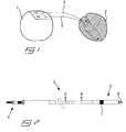
- fig 1in which is disclosed, in a schematic view, the connection of a pacemaker 1 to a heart 2 by means of two medical implantable leads 3. More precisely, one lead is connected to the right atrium and the other lead is connected to the right ventricle of the heart for monitoring and pacing of the heart rate.
- the pacemakeris normally adapted to be implanted under the skin of the patient, e.g. in the area of one of the collar bones, and the leads can preferably be inserted through a vein leading to the heart. It is to be noted that the reproduction scale of the pacemaker and the heart in the view of fig 1 are different for simplified drawing.
- a medical implantable lead 3which has been shortened for simplified drawing.
- the leadcomprises a connector 4 in a proximal end for connection to the pacemaker, an intermediate flexible lead portion, and a so called header 5 in a distal end.
- the headeris provided with a helix 6, which can be screwed out in the axial direction of the lead from a cavity in the distal end of the header.
- the helixhas the function of attaching the distal end of the lead to the heart, by being screwed into the tissue, and may also function as an electrode for receiving and/or transmitting electrical signals from and to the tissue, respectively.
- the headermay also be provided with a second electrode 7, a so called indifferent electrode, which is formed as a ring and positioned a small distance from the distal end and has the purpose of forming a complete current path together with the helix.
- fig 3is a partly longitudinal section and a partly cut through view of a first embodiment of the medical implantable lead along the line A-A in fig 2 .
- the leadcomprises an inner wire coil 8, an outer wire coil 9 and an outer protecting, fluidtight and flexible tube 10.
- the inner as well as the outer wire coilsare each comprised of one close-lapped wire 11 which forms an inner bore and, as can be seen, the inner wire coil is concentric positioned within the inner bore of the outer wire coil.
- the wireis composed of an electrically conducting central wire core 12, a surrounding electrically insulating layer 13 and, on the outside of the insulating layer, a surrounding electrically conducting shield layer 14.
- the central wire core 12 of the inner wire coil 8is electrically connected to the helix electrode 6, whereas the central wire core 12 of the outer wire coil 9 is connected to the second electrode 7. Since both of the wire coils are close-lapped, the outer electrically conducting shield layer 14 of each of the wires 11 in the inner and outer wire coils 8, 9, respectively, will form a continuous conducting path along the outside as well as the inside of each wire coil.
- this conducting pathformed by the outer conducting shield layers of the wires
- an effective shieldis obtained for the wire core 12, which is utilized for conducting signals between the pacemaker 1 and the heart 2.
- the shield layers of the wire coilscan both be arranged with electrically bonding or only one of them according to what is most appropriate in each individual case.
- any induced current from an external electromagnetic fieldwill induce a high frequency current moving in the axial direction of the lead illustrated by a horizontal bidirectional arrow 15 in fig 3 .
- the signals between the pacemaker and the electrodeswill move within the wire core 12 in the direction of the nearly vertical bidirectional arrow 16 in fig 3 .
- an angle ⁇ between the wire and a line being perpendicular to the coil axisis approximately 3° and consequently the angle between the coil axis and the wire is approximately 87°. This means that any current induced into the shield layer 14 will in its turn be restrained from being induced into the signal conducting wire core 12, as discussed hereinbefore.
- fig 4in which is illustrated an embodiment being similar to fig 3 except that only the outer wire coil 9 is composed of a wire 11 having a central wire core 12, an insulating layer 13 and a shield layer 14, as in the embodiment according to fig 3 and as shown in fig 6 , while the inner wire coil 8 is composed of a plain electrical conducting wire 17 having neither an insulating layer nor a shield layer. Accordingly, only the outer wire coil 9 is shielded.
- an inner flexible tube 18 of an electrically insulating materialis arranged in the area between the inner and outer wire coils.
- a third embodiment of a medical implantable leadaccording to the invention.
- This embodimentcomprises an inner wire coil 8, an outer wire coil 9 and an outer protecting, fluidtight and flexible tube 10, i.e. similar to the embodiment of fig 3 .
- the outer wire coil 9is formed of a wire 11 having an inner wire core 12, a surrounding insulating layer 13 and an outer surrounding shield layer 14.
- the inner wire coil 8is in this embodiment formed of a wire 19, as illustrated in fig 7 , which only has an inner wire core 12 and a surrounding electrically insulating layer 13. I.e. a surrounding shield layer is missing in this embodiment of the wire.
- the main part of the electromagnetic radiationwill be absorbed by the shield layer 14 at the outer wire coil 9.
- the induced current in the outer wire coilwill in its turn have difficulties to be induced over to the inner wire coil, since the induced current in the outer wire coil will be directed in the axial direction of the lead, i.e. in parallel to the arrow 15, while the inner wire coil 8 will only have one conducting direction along the wire core 12, i.e. in parallel to the arrow 16 and almost 90° in relation to the axial direction of the lead, due to the insulating layer 13 and the absence of any shield layer.
- the embodiment of fig 5is not formed with an inner coil having a surrounding shield layer conducting an induced current all around the wire core 12, which might further restrain current from being induced into the wire core of the inner coil.
- the wire of the inner coil in the embodiment of fig 5is provided with an insulating layer such that the conducting path in the wire core 12 will be in the direction of the wires and not in the axial direction of the lead as in the embodiment of fig 4 , which also may further restrain current from being induced into the wire core of the inner lead.
Landscapes
- Health & Medical Sciences (AREA)
- Heart & Thoracic Surgery (AREA)
- Nuclear Medicine, Radiotherapy & Molecular Imaging (AREA)
- Cardiology (AREA)
- Engineering & Computer Science (AREA)
- Biomedical Technology (AREA)
- Radiology & Medical Imaging (AREA)
- Life Sciences & Earth Sciences (AREA)
- Animal Behavior & Ethology (AREA)
- General Health & Medical Sciences (AREA)
- Public Health (AREA)
- Veterinary Medicine (AREA)
- Vascular Medicine (AREA)
- Electrotherapy Devices (AREA)
Description
- The present invention relates to a medical implantable lead of the kind being adapted to be implanted into a human or animal body for monitoring and/or controlling of an organ inside the body, comprising a fixation means in a distal end which is adapted to fixate the distal end of the lead to the organ, an electrode member in the distal end adapted to be in contact with tissue of the organ and receive and/or transmit electrical signals from and/or to the organ, and at least one electrically conducting coil, which includes one or more electrically conducting helical wires and which is adapted to connect the electrode member in the distal end with a monitoring and/or controlling device in a proximal end of the lead.
- It is well known in the art to use a medical implantable lead of the above kind to monitor and/or control the function of an organ inside a human or animal body, for example to monitor and/or control a heart by means of a monitoring and/or controlling device in form of a pacemaker or cardiac defibrillator connected to the proximal end of the lead. The medical implantable lead is provided with at least one electrical conductor in form of a coil having one or more helically formed electrical conducting wires. The lead is, in its distal end, provided with one or more electrodes, which is adapted to be in contact with the tissue of the organ and which is connected to the one or more electrical conducting coils, for receiving and/or transmitting electrical signals from and/or to the organ. The electrodes can optionally be formed as a contact electrode, abutting against a surface of the organ, as a penetrating electrode being penetrated through a surface of the organ and embedded within the tissue, or as a so called indifferent electrode which is surrounded by body fluids such as blood.
- Normally, such medical implantable leads are not considered to be compatible with Magnetic Resonance Imaging (MRI), i.e. persons or animals having such a lead implanted into the body, are excluded from being examined by MRI scanning. This is due to the fact that the electromagnetic field, that is generated during the MRI scanning, will induce a current in the conductor, which connects the one or more electrodes in the distal end of the medical implantable lead with the monitoring and/or controlling device in the proximal end of the lead. This induced current may cause heating in the electrode being in contact with the tissue of the organ. If the heating is too high, there is a risk that this will cause damages to the tissue. However, the use of MRI scanning for diagnostics is growing extensively and an increasing number of the population having a lead implanted, would benefit from MRI scans.
- It is thus desirable to reduce any heating at or close to the lead tip to acceptable and safe levels. It is known in the art to provide such medical implantable leads with an electrical shielding, in form of a tube of braided wires, which surrounds the coil and which in its proximal end normally is connected to the casing of the monitoring and/or controlling device. However, such shielded medical implantable leads are associated with several disadvantages. On the one hand, the braided shielding will give the medical implantable lead an increased thickness as well as increased rigidity, which normally is not desirable. On the other hand, the braided shielding will considerably increase the costs for manufacturing the lead, since it will involve the provision of one additional component, which has to be mounted when assembling the lead. Also, it has appeared that such a braided shielding can not prevent the induction of electrical current to the coiled conductor in a degree that is sufficient to, without risk, expose an individual, having an implanted lead, to a MRI scanning.
US 200810132985 A1 WO 2007/047966 A2 discloses an MRI/RF compatible medical interventional device. A plurality of spaced apart high impedance circuit segments have high impedance at a high range of radio frequencies and a low impedance at a low range of frequencies. The high impedance circuit segments comprise co-wound coiled inductors.- It is an object of the invention to provide a medical implantable lead having an improved shielding in relation to prior art. More specifically, it is an object to provide a shielded medical implantable lead, by which the shielding can be made with excellent shielding properties and in a cost-saving way. Atleast this object is achieved by a medical implantable lead according to
claim 1. - The invention is defined in the appended claims. Aspects, embodiments and examples disclosed of the present disclosure which do not fall under the scope of the appended claims do not form part of the invention and are merely provided for illustrative purposes.
- Accordingly, the basis of the invention is the insight that the above object may be achieved by manufacturing the conductor coil from one wire, which has an electrically conducting central wire core provided with a surrounding electrically insulating layer and also a surrounding electrically conducting shield layer on the outside of the insulating layer. One such composite wires, having such a structure, is thereafter helically formed to a close-lapped coil. During operation the wire core is utilized for conduction of signals, normally low frequency signals, between the electrode and the monitoring and/or controlling device, whereas the outer electrically conducting shield layer will function as a shielding for preventing or at least restricting an electromagnetic field from MRI scanning, or from some other type of source, to induce voltage/current into the wire core. At least one end of the shield layer is preferably connected to a casing of the monitoring and/or controlling device for electrical bonding of the shield.
- Several advantages may be achieved by a medical implantable lead formed in this way. One advantage is that a wire coil having an electrical shielding according to the invention, may be manufactured to a cost that is not significantly higher than for manufacturing a regular coil without any shielding.
- Another advantage is that the shielding properties for a wire coil according to the invention, will be improved in relation to a regular shielding in form of a tube of braided wires. This is due to the fact that, since the coil is close-lapped and adjacent loops of the coil will normally be in contact with each other, the conducting path for the induced electric current in the shield layer will be directed in the longitudinal direction of the lead, while the conducting path for the signals in the wire core will be directed in the longitudinal direction of the wires, i.e. nearly 90° in relation to each other since the wire is close-lapped. Small spacings may sometimes be formed between adjacent loops when the lead is bent. However, the small capacitance occuring at the near lying shield layers, will act as a shortage for the high frequency signals such that electric contact and a conducting path in the longitudinal direction of the lead is nevertheless maintained. However, the possible electric current induced into the outer conducting shield layer, will in its turn have a low susceptibility of inducing its electric current into the wire core since their mutual direction of current flow, will have a large angle, of almost 90° in relation to each other. Moreover, any current induced from the electromagnetic field and from the current in the outer conducting shielding layer into the wire core of the coil will, since it usually concerns electromagnetic fields of very high frequencies, generally radio frequencies of about 30 MHz or more, experience a very high impedance in the coiled conductor which effectively will counteract any induced current in the wire coil. Also, the reactance between adjacent loops of the central wire core will be rather high due to the insulation layer around the wire core, such that the capacitive coupling between adjacent loops will be low which effectively will reduce any current flow due to capacitive coupling.
- It is also an advantage that the present invention will result in a less increment of the diameter and the stiffness of the wire coil in comparison with using an ordinary shielding in form of a tube of braided wires, since the shield layer may be formed with a small thickness.
- A medical implantable lead according to the invention can be modified in many different ways. A common embodiment of a medical implantable lead comprises two electrically conducting wire coils, which are concentric positioned with one inside the other and which are connected to separate electrodes in the distal end of the lead. One electrode can be in form of a helix, which is connected to the inner wire coil and which is adapted to be screwed into the tissue and accordingly also serves the double function of attaching the distal end of the lead to the organ. The rotating of the helix can optionally be performed by rotating of the inner wire coil in relation to the outer wire coil, as is common knowledge within the art. The outer wire coil, in its turn, can be connected to an indifferent electrode, e.g. a ring formed electrode on the outer circumference of the distal end.
- However, also other embodiments are conceivable. For example a medical implantable lead having only one wire coil. In most cases each wire coil forms only one single conductor which, even if it is composed of two or more individual wires and thereby not form part of the invention, is connected to one single electrode. However, it is possible that a wire coil may contain two or more individual conductor wires, which are co-radially wound to form the wire coil and which are connected to different electrodes and thereby not forming part of the invention. The lead may comprise more than two electrodes and accordingly also more than two individual conductors. Moreover, the electrodes may be formed in other ways than as a rotatable helix or a ring-formed electrode. For example it can be some other type of penetrating electrode having barbes or the like, or be a contact electrode adapted to abut against a surface of the organ. Also, a fixation means does not need to be penetrating or to have the function of an electrode. Instead the fixation means may be of a type which e.g. is adapted to engage in the trabecular network inside a heart and may have only a fixating function and be combined with a separate electrode, for instance a contact electrode abutting against the surface of the tissue.
- In case the medical implantable lead comprises two or more wire coils, it is within the scope of the invention that only one, all of them, or an arbitrary number of the wire coils are provided with a wire core, a surrounding insulating layer and a surrounding conducting shield layer, according to the invention. The chosen configuration may vary depending on the actual field of application, the required characteristics and the like. Normally, the most critical electrode with regard to heating problems due to induced electromagnetic radiation, is an electrode being in direct contact with the tissue, such as an electrode penetrated into the tissue or abutting against a surface, while an indifferent electrode being only in contact with body fluids, normally is not critical since it often has a rather large surface which will give low current density and the body fluids will cause sufficient cooling of the electrode. However, even if an electrode that is in direct contact with the tissue, is connected to an inner wire coil and there is provided also an outer wire coil, it may be
beneficial to arrange the outer wire coil with an insulating layer and a conducting shield layer, according to the invention, in case only one of the wire coils are to be shielded. This is due to the fact that in such case the main part of the electromagnetic field will be absorbed by a shielding being positioned on a comparatively long distance from the most critical inner wire coil, having the result that the inductive as well as the capacitive coupling to the inner wire coil will be rather poor. - Prior art medical implantable leads having two uninsulated wire coils, are normally separated by a flexible tube of an insulating material positioned between the wire coils, in order to maintain the signals in the respective wire coils separated from each other. By a medical implantable lead according to the invention, where both of the wire coils are provided with a surrounding insulating layer and a surrounding conducting shield layer, such an intermediate flexible tube may be dispensed with since the inner signal conducting wire cores are insulated from each other. In such a case the inner and outer wire coils will have a common shielding since the outer surrounding conducting shield layer of each wire coil will be in contact with each other. However, it is also conceivable that only one wire coil is provided with a surrounding conducting shield layer whereas the other is provided with only a surrounding insulating layer, as in a hereinafter described and illustrated embodiment.
- In an actual embodiment of the invention, the inner conducting wire core may have of diameter of about 0,1 - 0,15 mm, the surrounding insulating layer may have a thickness of about 0,02 - 0,1 mm and the surrounding conductive shield layer may have a thickness of about 1 - 50µm. However, also other dimensions could be conceivable. The insulating layer could for example be an oxide layer, silicon, polyurethane, a combination of those, fluorinated hydrocarbon, e.g. ETFE, polyimide, polyamide, etc. The outer surrounding conducting shield layer may be a metal such as a noble metal, e.g. gold, but also electrical conducting non-metals could be conceivable. The insulating layer as well as the shield layer are preferably applied when the wire is in a straight condition and thereafter the wire is wounded to a coil. The shield layer may be applied by means of any suitable method, such as by means of e.g. plasma sputtering, physical vapour deposition, physical vapour decomposition, electrochemical bath, etc.
- The thickness of the shield layer will influence the shielding characteristics and is also dependant of the conductance of the material as well as the frequency of the electromagnetic field. By means of a customary braided shield, the characteristics are hard to control. However, with a shield layer according to the invention, the thickness of the shield layer can be controlled within very narrow limits, such that the shielding characteristics may be very close adapted to a specific electromagnetic field, such as from MRI scanning.
- The angle between the axial direction of the lead, i.e. the direction which the induced current in the electrical conducting shield layer will have, and the direction of the inner wire core, i.e. the direction of the signals between the electrode and the monitoring and/or controlling device, is dependant of the outer diameter of the wire, the diameter of the wire coil and the number of wires in the wire coil. If, for example, the wire coil comprises two or more individual wires, the angle will be smaller than if the wire coil only comprises one single wire, since with two or more wires the pitch of the helically wound wires will increase. Generally, it is advantageous the larger the angle is and it is preferred that the angle is at least 70°.
- The invention will hereinafter be described by way of example by reference to embodiments illustrated in the accompanying drawings, in which:
- Fig 1
- is a schematic view illustrating connection of a pacemaker to a heart by means of two medical implantable leads;
- Fig 2
- is a view of a shortened medical implantable lead;
- Fig 3
- is a partly longitudinal section and partly cut view through a medical implantable lead according to a first embodiment of the invention;
- Fig 4
- is a partly longitudinal section and partly cut through view through a medical implantable lead according to a second embodiment of the invention;
- Fig 5
- is a partly longitudinal section and partly cut through view through a medical implantable lead according to a third embodiment of the invention;
- Fig 6
- is a cross section of a wire having a wire core, an insulating layer and a shield layer; and
- Fig 7
- is a cross section of a wire having a wire core and an insulating layer.
- Reference is first made to
fig 1 , in which is disclosed, in a schematic view, the connection of apacemaker 1 to a heart 2 by means of two medical implantable leads 3. More precisely, one lead is connected to the right atrium and the other lead is connected to the right ventricle of the heart for monitoring and pacing of the heart rate. The pacemaker is normally adapted to be implanted under the skin of the patient, e.g. in the area of one of the collar bones, and the leads can preferably be inserted through a vein leading to the heart. It is to be noted that the reproduction scale of the pacemaker and the heart in the view offig 1 are different for simplified drawing. - In
fig 2 is illustrated a medicalimplantable lead 3, which has been shortened for simplified drawing. The lead comprises aconnector 4 in a proximal end for connection to the pacemaker, an intermediate flexible lead portion, and a so calledheader 5 in a distal end. The header is provided with ahelix 6, which can be screwed out in the axial direction of the lead from a cavity in the distal end of the header. The helix has the function of attaching the distal end of the lead to the heart, by being screwed into the tissue, and may also function as an electrode for receiving and/or transmitting electrical signals from and to the tissue, respectively. The header may also be provided with asecond electrode 7, a so called indifferent electrode, which is formed as a ring and positioned a small distance from the distal end and has the purpose of forming a complete current path together with the helix. - Reference it then made to
fig 3 , which is a partly longitudinal section and a partly cut through view of a first embodiment of the medical implantable lead along the line A-A infig 2 . The lead comprises aninner wire coil 8, anouter wire coil 9 and an outer protecting, fluidtight andflexible tube 10. The inner as well as the outer wire coils are each comprised of one close-lappedwire 11 which forms an inner bore and, as can be seen, the inner wire coil is concentric positioned within the inner bore of the outer wire coil. - With reference also to
fig 6 , which illustrates a cross section through thewire 11 of the inner as well as theouter wire coil central wire core 12, a surrounding electrically insulatinglayer 13 and, on the outside of the insulating layer, a surrounding electrically conductingshield layer 14. Thecentral wire core 12 of theinner wire coil 8 is electrically connected to thehelix electrode 6, whereas thecentral wire core 12 of theouter wire coil 9 is connected to thesecond electrode 7. Since both of the wire coils are close-lapped, the outer electrically conductingshield layer 14 of each of thewires 11 in the inner andouter wire coils pacemaker 1 or the like, an effective shield is obtained for thewire core 12, which is utilized for conducting signals between thepacemaker 1 and the heart 2. The shield layers of the wire coils can both be arranged with electrically bonding or only one of them according to what is most appropriate in each individual case. - Since the shield layers each forms a continuous conducting path along the lead, any induced current from an external electromagnetic field, will induce a high frequency current moving in the axial direction of the lead illustrated by a horizontal
bidirectional arrow 15 infig 3 . The signals between the pacemaker and the electrodes, on the other hand, will move within thewire core 12 in the direction of the nearly verticalbidirectional arrow 16 infig 3 . This has the effect that the directions of any induced current in the shield layer and the signals inside the wire core will be nearly 90° in relation to each other. In the embodiments offig 3 and 6 , an angleα between the wire and a line being perpendicular to the coil axis, is approximately 3° and consequently the angle between the coil axis and the wire is approximately 87°. This means that any current induced into theshield layer 14 will in its turn be restrained from being induced into the signalconducting wire core 12, as discussed hereinbefore. - Reference is then made to
fig 4 , in which is illustrated an embodiment being similar tofig 3 except that only theouter wire coil 9 is composed of awire 11 having acentral wire core 12, an insulatinglayer 13 and ashield layer 14, as in the embodiment according tofig 3 and as shown infig 6 , while theinner wire coil 8 is composed of a plainelectrical conducting wire 17 having neither an insulating layer nor a shield layer. Accordingly, only theouter wire coil 9 is shielded. In order to prevent theinner wire coil 8 from being shortcircuited by contact with the shield layer of the outer wire coil, also an innerflexible tube 18 of an electrically insulating material is arranged in the area between the inner and outer wire coils. - In
fig 5 is illustrated a third embodiment of a medical implantable lead according to the invention. This embodiment comprises aninner wire coil 8, anouter wire coil 9 and an outer protecting, fluidtight andflexible tube 10, i.e. similar to the embodiment offig 3 . As in the embodiment infig 3 , theouter wire coil 9 is formed of awire 11 having aninner wire core 12, a surrounding insulatinglayer 13 and an outersurrounding shield layer 14. However, theinner wire coil 8 is in this embodiment formed of awire 19, as illustrated infig 7 , which only has aninner wire core 12 and a surrounding electrically insulatinglayer 13. I.e. a surrounding shield layer is missing in this embodiment of the wire. This can be advantageous in so far as in this case the main part of the electromagnetic radiation will be absorbed by theshield layer 14 at theouter wire coil 9. The induced current in the outer wire coil will in its turn have difficulties to be induced over to the inner wire coil, since the induced current in the outer wire coil will be directed in the axial direction of the lead, i.e. in parallel to thearrow 15, while theinner wire coil 8 will only have one conducting direction along thewire core 12, i.e. in parallel to thearrow 16 and almost 90° in relation to the axial direction of the lead, due to the insulatinglayer 13 and the absence of any shield layer. In comparison to the embodiment according tofig 3 , the embodiment offig 5 is not formed with an inner coil having a surrounding shield layer conducting an induced current all around thewire core 12, which might further restrain current from being induced into the wire core of the inner coil. On the other hand, in comparison to the embodiment according tofig 4 , the wire of the inner coil in the embodiment offig 5 is provided with an insulating layer such that the conducting path in thewire core 12 will be in the direction of the wires and not in the axial direction of the lead as in the embodiment offig 4 , which also may further restrain current from being induced into the wire core of the inner lead. - It is obvious for those skilled in the art that this invention is applicable for any type of medical implantable lead, e.g. for an implantable pulse generator such as ICD, neurostimulators etc.
Claims (7)
- A medical implantable lead (3) of the kind being adapted to be implanted into a human or animal body for monitoring and/or controlling of an organ (2) inside the body, comprising:an electrode member in a distal end of the medical implantable lead (3) adapted to be in contact with tissue of the organ (2) and receive and/or transmit electrical signals from and/or to the organ (2), andan electrically conducting coil (8, 9), which is adapted to connect the electrode member in the distal end with a monitoring and/or controlling device (1) in a proximal end of the medical implantable lead (3), wherein an electrically conducting helical wire (11) of the electrically conducting coil (8, 9) comprises a wire core (12) which is provided with a surrounding electrically insulating layer (13), which in its turn is provided with a surrounding electrically conducting shield layer (14), wherein the electrically conducting coil (8, 9) is close-lapped such that electrically conducting shield layers of adjacent loops of the electrically conducting coil (8, 9) are in electrical contact with each other,characterized by:a fixation means (6) in the distal end, which is adapted to fixate the distal end to the organ (2), wherein the electrically conducting coil (8, 9) includes only one electrically conducting helical wire (11).
- A medical implantable lead according to claim 1,characterized in that it comprises two electrically conducting coils (8, 9), of which at least one comprises only one electrically conducting helical wire (11) including a central wire core (12) with a surrounding electrically insulating layer (13) and a surrounding electrically conducting shield layer (14).
- A medical implantable lead according to claim 2,characterized in that the fixation means (6) is a helix electrode, which is adapted to be screwed into the issue of the organ (2), and the electrode member is an indifferent electrode (7), wherein the electrically conducting coil (8, 9) is an outer wire coil (9) and the medical implantable lead (3) further comprises an inner wire coil (8), which includes only one electrically conducting helical wire (11), which is close-lapped and which is adapted to connect the fixation electrode (6) in the distal end with the monitoring and/or controlling device (1) in the proximal end.
- A medical implantable lead according to claim 3,characterized in that the electrically conductive helical wire (11) of the inner wire coil (8) comprises a wire core (12) which is provided with a surrounding electrically insulating layer (13), which in its turn is provided with a surrounding electrically conductive shield layer (14) and the inner wire coil (8) is close-lapped such that electrically conducting shield layers of adjacent turns of the inner wire coil (8) are in electrical contact with each other.
- A medical implantable lead according to claim 2,characterized in that the electrically conductive helical wire (11) of the inner wire coil (8) comprises a wire core (12) having neither a surrounding electrically insulating layer nor a surrounding electrically conductive shield layer, the medical implantable lead (3) comprises an inner flexible tube (18) of an electrically insulating material arranged in an area between the inner wire coil (8) and the outer wire coil (9).
- A medical implantable lead according to any of the preceding claims,characterized in that the surrounding electrically insulating layer (13) is between 0.02 and 0.1 mm.
- A medical implantable lead according to any of the preceding claims,characterized in that the electrically conducting shield layer (14) is between 1 and 50 µm.
Applications Claiming Priority (1)
| Application Number | Priority Date | Filing Date | Title |
|---|---|---|---|
| PCT/SE2008/000678WO2010064962A1 (en) | 2008-12-02 | 2008-12-02 | A medical implantable lead and a method for manufacturing the same |
Publications (3)
| Publication Number | Publication Date |
|---|---|
| EP2373377A1 EP2373377A1 (en) | 2011-10-12 |
| EP2373377A4 EP2373377A4 (en) | 2012-04-25 |
| EP2373377B1true EP2373377B1 (en) | 2018-05-30 |
Family
ID=42233454
Family Applications (1)
| Application Number | Title | Priority Date | Filing Date |
|---|---|---|---|
| EP08878622.3ANot-in-forceEP2373377B1 (en) | 2008-12-02 | 2008-12-02 | A medical implantable lead |
Country Status (3)
| Country | Link |
|---|---|
| US (1) | US8442647B2 (en) |
| EP (1) | EP2373377B1 (en) |
| WO (1) | WO2010064962A1 (en) |
Cited By (1)
| Publication number | Priority date | Publication date | Assignee | Title |
|---|---|---|---|---|
| WO2022057159A1 (en)* | 2020-09-17 | 2022-03-24 | 北京品驰医疗设备有限公司 | Connection mechanism for implantable medical device and manufacturing method therefor |
Families Citing this family (4)
| Publication number | Priority date | Publication date | Assignee | Title |
|---|---|---|---|---|
| EP2514479B1 (en) | 2011-04-21 | 2013-12-25 | St. Jude Medical AB | A medical implantable lead |
| JP5786660B2 (en)* | 2011-11-08 | 2015-09-30 | スミダコーポレーション株式会社 | Magnetic component and method of manufacturing magnetic component |
| US9463317B2 (en)* | 2012-04-19 | 2016-10-11 | Medtronic, Inc. | Paired medical lead bodies with braided conductive shields having different physical parameter values |
| US20220143411A1 (en)* | 2020-11-06 | 2022-05-12 | Advanced Neuromodulation Systems, Inc. | Systems and methods to reduce rf-induced heating of an implanted lead |
Family Cites Families (9)
| Publication number | Priority date | Publication date | Assignee | Title |
|---|---|---|---|---|
| US5545201A (en)* | 1995-03-29 | 1996-08-13 | Pacesetter, Inc. | Bipolar active fixation lead for sensing and pacing the heart |
| US20030144718A1 (en) | 2002-01-29 | 2003-07-31 | Zeijlemaker Volkert A. | Method and apparatus for shielding coating for MRI resistant electrode systems |
| US20030144719A1 (en) | 2002-01-29 | 2003-07-31 | Zeijlemaker Volkert A. | Method and apparatus for shielding wire for MRI resistant electrode systems |
| US7158837B2 (en)* | 2002-07-10 | 2007-01-02 | Oscor Inc. | Low profile cardiac leads |
| US7877150B2 (en) | 2004-03-30 | 2011-01-25 | Medtronic, Inc. | Lead electrode for use in an MRI-safe implantable medical device |
| CA2623453C (en)* | 2005-10-21 | 2016-02-09 | Surgi-Vision, Inc. | Mri-safe high impedance lead systems and related methods |
| US7610101B2 (en)* | 2006-11-30 | 2009-10-27 | Cardiac Pacemakers, Inc. | RF rejecting lead |
| US10537730B2 (en) | 2007-02-14 | 2020-01-21 | Medtronic, Inc. | Continuous conductive materials for electromagnetic shielding |
| US8275464B2 (en)* | 2007-12-06 | 2012-09-25 | Cardiac Pacemakers, Inc. | Leads with high surface resistance |
- 2008
- 2008-12-02WOPCT/SE2008/000678patent/WO2010064962A1/enactiveApplication Filing
- 2008-12-02EPEP08878622.3Apatent/EP2373377B1/ennot_activeNot-in-force
- 2008-12-02USUS13/132,125patent/US8442647B2/ennot_activeExpired - Fee Related
Non-Patent Citations (1)
| Title |
|---|
| None* |
Cited By (1)
| Publication number | Priority date | Publication date | Assignee | Title |
|---|---|---|---|---|
| WO2022057159A1 (en)* | 2020-09-17 | 2022-03-24 | 北京品驰医疗设备有限公司 | Connection mechanism for implantable medical device and manufacturing method therefor |
Also Published As
| Publication number | Publication date |
|---|---|
| WO2010064962A1 (en) | 2010-06-10 |
| EP2373377A1 (en) | 2011-10-12 |
| EP2373377A4 (en) | 2012-04-25 |
| US20110245646A1 (en) | 2011-10-06 |
| US8442647B2 (en) | 2013-05-14 |
Similar Documents
| Publication | Publication Date | Title |
|---|---|---|
| US8521307B2 (en) | Implantable MRI compatible medical lead | |
| JP5430671B2 (en) | Lead wire with high surface resistance | |
| US8433421B2 (en) | MRI-safe high impedance lead systems | |
| EP2282807B1 (en) | Medical lead coil conductor with spacer element | |
| JP5149399B2 (en) | Lead with design features compatible with MRI | |
| US8369964B2 (en) | MRI compatible medical device lead including transmission line notch filters | |
| US20090270956A1 (en) | Implantable medical lead configured for improved mri safety | |
| US9504822B2 (en) | Inductive element for providing MRI compatibility in an implantable medical device lead | |
| EP2373377B1 (en) | A medical implantable lead | |
| EP2121119B1 (en) | Medical electrical lead body designs incorporating energy dissipating shunt | |
| US9517335B2 (en) | Implantable electrical line |
Legal Events
| Date | Code | Title | Description |
|---|---|---|---|
| PUAI | Public reference made under article 153(3) epc to a published international application that has entered the european phase | Free format text:ORIGINAL CODE: 0009012 | |
| 17P | Request for examination filed | Effective date:20110704 | |
| AK | Designated contracting states | Kind code of ref document:A1 Designated state(s):AT BE BG CH CY CZ DE DK EE ES FI FR GB GR HR HU IE IS IT LI LT LU LV MC MT NL NO PL PT RO SE SI SK TR | |
| DAX | Request for extension of the european patent (deleted) | ||
| A4 | Supplementary search report drawn up and despatched | Effective date:20120326 | |
| RIC1 | Information provided on ipc code assigned before grant | Ipc:A61N 1/05 20060101ALI20120320BHEP Ipc:H01B 7/04 20060101ALI20120320BHEP Ipc:A61N 1/37 20060101ALN20120320BHEP Ipc:A61N 1/08 20060101AFI20120320BHEP | |
| 17Q | First examination report despatched | Effective date:20171114 | |
| GRAP | Despatch of communication of intention to grant a patent | Free format text:ORIGINAL CODE: EPIDOSNIGR1 | |
| RIC1 | Information provided on ipc code assigned before grant | Ipc:A61N 1/08 20060101AFI20180115BHEP Ipc:A61N 1/05 20060101ALI20180115BHEP Ipc:A61N 1/37 20060101ALN20180115BHEP Ipc:H01B 7/04 20060101ALI20180115BHEP | |
| INTG | Intention to grant announced | Effective date:20180214 | |
| RIN1 | Information on inventor provided before grant (corrected) | Inventor name:STRANDBERG, HANS Inventor name:HENRIQUEZ, LEDA Inventor name:PELLIJEFF, GUSTAV Inventor name:BROOME, ASA Inventor name:DAHLBERG, KENNETH Inventor name:SIVARD, AKE | |
| GRAS | Grant fee paid | Free format text:ORIGINAL CODE: EPIDOSNIGR3 | |
| GRAA | (expected) grant | Free format text:ORIGINAL CODE: 0009210 | |
| AK | Designated contracting states | Kind code of ref document:B1 Designated state(s):AT BE BG CH CY CZ DE DK EE ES FI FR GB GR HR HU IE IS IT LI LT LU LV MC MT NL NO PL PT RO SE SI SK TR | |
| REG | Reference to a national code | Ref country code:GB Ref legal event code:FG4D | |
| REG | Reference to a national code | Ref country code:CH Ref legal event code:EP | |
| REG | Reference to a national code | Ref country code:CH Ref legal event code:NV Representative=s name:E. BLUM AND CO. AG PATENT- UND MARKENANWAELTE , CH Ref country code:AT Ref legal event code:REF Ref document number:1002986 Country of ref document:AT Kind code of ref document:T Effective date:20180615 | |
| REG | Reference to a national code | Ref country code:IE Ref legal event code:FG4D | |
| REG | Reference to a national code | Ref country code:DE Ref legal event code:R096 Ref document number:602008055488 Country of ref document:DE | |
| REG | Reference to a national code | Ref country code:NL Ref legal event code:MP Effective date:20180530 | |
| REG | Reference to a national code | Ref country code:LT Ref legal event code:MG4D | |
| PG25 | Lapsed in a contracting state [announced via postgrant information from national office to epo] | Ref country code:FI Free format text:LAPSE BECAUSE OF FAILURE TO SUBMIT A TRANSLATION OF THE DESCRIPTION OR TO PAY THE FEE WITHIN THE PRESCRIBED TIME-LIMIT Effective date:20180530 Ref country code:BG Free format text:LAPSE BECAUSE OF FAILURE TO SUBMIT A TRANSLATION OF THE DESCRIPTION OR TO PAY THE FEE WITHIN THE PRESCRIBED TIME-LIMIT Effective date:20180830 Ref country code:CY Free format text:LAPSE BECAUSE OF FAILURE TO SUBMIT A TRANSLATION OF THE DESCRIPTION OR TO PAY THE FEE WITHIN THE PRESCRIBED TIME-LIMIT Effective date:20180530 Ref country code:LT Free format text:LAPSE BECAUSE OF FAILURE TO SUBMIT A TRANSLATION OF THE DESCRIPTION OR TO PAY THE FEE WITHIN THE PRESCRIBED TIME-LIMIT Effective date:20180530 Ref country code:NO Free format text:LAPSE BECAUSE OF FAILURE TO SUBMIT A TRANSLATION OF THE DESCRIPTION OR TO PAY THE FEE WITHIN THE PRESCRIBED TIME-LIMIT Effective date:20180830 Ref country code:SE Free format text:LAPSE BECAUSE OF FAILURE TO SUBMIT A TRANSLATION OF THE DESCRIPTION OR TO PAY THE FEE WITHIN THE PRESCRIBED TIME-LIMIT Effective date:20180530 Ref country code:ES Free format text:LAPSE BECAUSE OF FAILURE TO SUBMIT A TRANSLATION OF THE DESCRIPTION OR TO PAY THE FEE WITHIN THE PRESCRIBED TIME-LIMIT Effective date:20180530 | |
| PG25 | Lapsed in a contracting state [announced via postgrant information from national office to epo] | Ref country code:GR Free format text:LAPSE BECAUSE OF FAILURE TO SUBMIT A TRANSLATION OF THE DESCRIPTION OR TO PAY THE FEE WITHIN THE PRESCRIBED TIME-LIMIT Effective date:20180831 Ref country code:LV Free format text:LAPSE BECAUSE OF FAILURE TO SUBMIT A TRANSLATION OF THE DESCRIPTION OR TO PAY THE FEE WITHIN THE PRESCRIBED TIME-LIMIT Effective date:20180530 Ref country code:HR Free format text:LAPSE BECAUSE OF FAILURE TO SUBMIT A TRANSLATION OF THE DESCRIPTION OR TO PAY THE FEE WITHIN THE PRESCRIBED TIME-LIMIT Effective date:20180530 | |
| REG | Reference to a national code | Ref country code:AT Ref legal event code:MK05 Ref document number:1002986 Country of ref document:AT Kind code of ref document:T Effective date:20180530 | |
| PG25 | Lapsed in a contracting state [announced via postgrant information from national office to epo] | Ref country code:NL Free format text:LAPSE BECAUSE OF FAILURE TO SUBMIT A TRANSLATION OF THE DESCRIPTION OR TO PAY THE FEE WITHIN THE PRESCRIBED TIME-LIMIT Effective date:20180530 | |
| PG25 | Lapsed in a contracting state [announced via postgrant information from national office to epo] | Ref country code:RO Free format text:LAPSE BECAUSE OF FAILURE TO SUBMIT A TRANSLATION OF THE DESCRIPTION OR TO PAY THE FEE WITHIN THE PRESCRIBED TIME-LIMIT Effective date:20180530 Ref country code:SK Free format text:LAPSE BECAUSE OF FAILURE TO SUBMIT A TRANSLATION OF THE DESCRIPTION OR TO PAY THE FEE WITHIN THE PRESCRIBED TIME-LIMIT Effective date:20180530 Ref country code:CZ Free format text:LAPSE BECAUSE OF FAILURE TO SUBMIT A TRANSLATION OF THE DESCRIPTION OR TO PAY THE FEE WITHIN THE PRESCRIBED TIME-LIMIT Effective date:20180530 Ref country code:DK Free format text:LAPSE BECAUSE OF FAILURE TO SUBMIT A TRANSLATION OF THE DESCRIPTION OR TO PAY THE FEE WITHIN THE PRESCRIBED TIME-LIMIT Effective date:20180530 Ref country code:PL Free format text:LAPSE BECAUSE OF FAILURE TO SUBMIT A TRANSLATION OF THE DESCRIPTION OR TO PAY THE FEE WITHIN THE PRESCRIBED TIME-LIMIT Effective date:20180530 Ref country code:AT Free format text:LAPSE BECAUSE OF FAILURE TO SUBMIT A TRANSLATION OF THE DESCRIPTION OR TO PAY THE FEE WITHIN THE PRESCRIBED TIME-LIMIT Effective date:20180530 Ref country code:EE Free format text:LAPSE BECAUSE OF FAILURE TO SUBMIT A TRANSLATION OF THE DESCRIPTION OR TO PAY THE FEE WITHIN THE PRESCRIBED TIME-LIMIT Effective date:20180530 | |
| PGFP | Annual fee paid to national office [announced via postgrant information from national office to epo] | Ref country code:DE Payment date:20181114 Year of fee payment:11 | |
| PGFP | Annual fee paid to national office [announced via postgrant information from national office to epo] | Ref country code:IT Payment date:20181213 Year of fee payment:11 Ref country code:CH Payment date:20181030 Year of fee payment:11 Ref country code:FR Payment date:20181119 Year of fee payment:11 | |
| REG | Reference to a national code | Ref country code:DE Ref legal event code:R097 Ref document number:602008055488 Country of ref document:DE | |
| PLBE | No opposition filed within time limit | Free format text:ORIGINAL CODE: 0009261 | |
| STAA | Information on the status of an ep patent application or granted ep patent | Free format text:STATUS: NO OPPOSITION FILED WITHIN TIME LIMIT | |
| 26N | No opposition filed | Effective date:20190301 | |
| PG25 | Lapsed in a contracting state [announced via postgrant information from national office to epo] | Ref country code:SI Free format text:LAPSE BECAUSE OF FAILURE TO SUBMIT A TRANSLATION OF THE DESCRIPTION OR TO PAY THE FEE WITHIN THE PRESCRIBED TIME-LIMIT Effective date:20180530 | |
| GBPC | Gb: european patent ceased through non-payment of renewal fee | Effective date:20181202 | |
| PG25 | Lapsed in a contracting state [announced via postgrant information from national office to epo] | Ref country code:MC Free format text:LAPSE BECAUSE OF FAILURE TO SUBMIT A TRANSLATION OF THE DESCRIPTION OR TO PAY THE FEE WITHIN THE PRESCRIBED TIME-LIMIT Effective date:20180530 Ref country code:LU Free format text:LAPSE BECAUSE OF NON-PAYMENT OF DUE FEES Effective date:20181202 | |
| REG | Reference to a national code | Ref country code:IE Ref legal event code:MM4A | |
| REG | Reference to a national code | Ref country code:BE Ref legal event code:MM Effective date:20181231 | |
| PG25 | Lapsed in a contracting state [announced via postgrant information from national office to epo] | Ref country code:IE Free format text:LAPSE BECAUSE OF NON-PAYMENT OF DUE FEES Effective date:20181202 | |
| PG25 | Lapsed in a contracting state [announced via postgrant information from national office to epo] | Ref country code:BE Free format text:LAPSE BECAUSE OF NON-PAYMENT OF DUE FEES Effective date:20181231 | |
| PG25 | Lapsed in a contracting state [announced via postgrant information from national office to epo] | Ref country code:GB Free format text:LAPSE BECAUSE OF NON-PAYMENT OF DUE FEES Effective date:20181202 | |
| PG25 | Lapsed in a contracting state [announced via postgrant information from national office to epo] | Ref country code:MT Free format text:LAPSE BECAUSE OF NON-PAYMENT OF DUE FEES Effective date:20181202 | |
| PG25 | Lapsed in a contracting state [announced via postgrant information from national office to epo] | Ref country code:TR Free format text:LAPSE BECAUSE OF FAILURE TO SUBMIT A TRANSLATION OF THE DESCRIPTION OR TO PAY THE FEE WITHIN THE PRESCRIBED TIME-LIMIT Effective date:20180530 | |
| PG25 | Lapsed in a contracting state [announced via postgrant information from national office to epo] | Ref country code:PT Free format text:LAPSE BECAUSE OF FAILURE TO SUBMIT A TRANSLATION OF THE DESCRIPTION OR TO PAY THE FEE WITHIN THE PRESCRIBED TIME-LIMIT Effective date:20180530 | |
| PG25 | Lapsed in a contracting state [announced via postgrant information from national office to epo] | Ref country code:HU Free format text:LAPSE BECAUSE OF FAILURE TO SUBMIT A TRANSLATION OF THE DESCRIPTION OR TO PAY THE FEE WITHIN THE PRESCRIBED TIME-LIMIT; INVALID AB INITIO Effective date:20081202 | |
| REG | Reference to a national code | Ref country code:DE Ref legal event code:R119 Ref document number:602008055488 Country of ref document:DE | |
| PG25 | Lapsed in a contracting state [announced via postgrant information from national office to epo] | Ref country code:IS Free format text:LAPSE BECAUSE OF FAILURE TO SUBMIT A TRANSLATION OF THE DESCRIPTION OR TO PAY THE FEE WITHIN THE PRESCRIBED TIME-LIMIT Effective date:20180930 | |
| REG | Reference to a national code | Ref country code:CH Ref legal event code:PL | |
| PG25 | Lapsed in a contracting state [announced via postgrant information from national office to epo] | Ref country code:DE Free format text:LAPSE BECAUSE OF NON-PAYMENT OF DUE FEES Effective date:20200701 Ref country code:FR Free format text:LAPSE BECAUSE OF NON-PAYMENT OF DUE FEES Effective date:20191231 Ref country code:IT Free format text:LAPSE BECAUSE OF NON-PAYMENT OF DUE FEES Effective date:20191202 | |
| PG25 | Lapsed in a contracting state [announced via postgrant information from national office to epo] | Ref country code:CH Free format text:LAPSE BECAUSE OF NON-PAYMENT OF DUE FEES Effective date:20191231 Ref country code:LI Free format text:LAPSE BECAUSE OF NON-PAYMENT OF DUE FEES Effective date:20191231 |