EP2372052A2 - Access control device with electromechanical converter - Google Patents
Access control device with electromechanical converterDownload PDFInfo
- Publication number
- EP2372052A2 EP2372052A2EP20110450022EP11450022AEP2372052A2EP 2372052 A2EP2372052 A2EP 2372052A2EP 20110450022EP20110450022EP 20110450022EP 11450022 AEP11450022 AEP 11450022AEP 2372052 A2EP2372052 A2EP 2372052A2
- Authority
- EP
- European Patent Office
- Prior art keywords
- handle
- closing
- lock
- opening
- converter
- Prior art date
- Legal status (The legal status is an assumption and is not a legal conclusion. Google has not performed a legal analysis and makes no representation as to the accuracy of the status listed.)
- Granted
Links
- 230000033001locomotionEffects0.000claimsabstractdescription23
- 238000013475authorizationMethods0.000claimsabstractdescription8
- 238000011156evaluationMethods0.000claimsabstractdescription7
- 230000005540biological transmissionEffects0.000claimsdescription10
- 238000006243chemical reactionMethods0.000claimsdescription6
- 230000000903blocking effectEffects0.000claimsdescription2
- 239000003990capacitorSubstances0.000claimsdescription2
- 238000013016dampingMethods0.000claimsdescription2
- 238000006073displacement reactionMethods0.000description6
- 230000006698inductionEffects0.000description5
- 238000011161developmentMethods0.000description4
- 230000004907fluxEffects0.000description2
- 238000013095identification testingMethods0.000description2
- 238000009434installationMethods0.000description2
- 238000013519translationMethods0.000description2
- 238000012795verificationMethods0.000description2
- 230000004913activationEffects0.000description1
- 238000001994activationMethods0.000description1
- 230000006978adaptationEffects0.000description1
- 230000008859changeEffects0.000description1
- 238000010276constructionMethods0.000description1
- 230000000994depressogenic effectEffects0.000description1
- 238000013461designMethods0.000description1
- 230000010354integrationEffects0.000description1
- 230000007246mechanismEffects0.000description1
- 238000000034methodMethods0.000description1
- 238000010248power generationMethods0.000description1
- 230000008569processEffects0.000description1
- 238000011084recoveryMethods0.000description1
- 230000009467reductionEffects0.000description1
- 239000000725suspensionSubstances0.000description1
- 238000012549trainingMethods0.000description1
Images


Classifications
- E—FIXED CONSTRUCTIONS
- E05—LOCKS; KEYS; WINDOW OR DOOR FITTINGS; SAFES
- E05B—LOCKS; ACCESSORIES THEREFOR; HANDCUFFS
- E05B47/00—Operating or controlling locks or other fastening devices by electric or magnetic means
- E05B47/06—Controlling mechanically-operated bolts by electro-magnetically-operated detents
- E05B47/0611—Cylinder locks with electromagnetic control
- E05B47/0638—Cylinder locks with electromagnetic control by disconnecting the rotor
- E—FIXED CONSTRUCTIONS
- E05—LOCKS; KEYS; WINDOW OR DOOR FITTINGS; SAFES
- E05B—LOCKS; ACCESSORIES THEREFOR; HANDCUFFS
- E05B47/00—Operating or controlling locks or other fastening devices by electric or magnetic means
- E05B47/06—Controlling mechanically-operated bolts by electro-magnetically-operated detents
- E05B47/0611—Cylinder locks with electromagnetic control
- E05B47/0615—Cylinder locks with electromagnetic control operated by handles, e.g. by knobs
- E—FIXED CONSTRUCTIONS
- E05—LOCKS; KEYS; WINDOW OR DOOR FITTINGS; SAFES
- E05B—LOCKS; ACCESSORIES THEREFOR; HANDCUFFS
- E05B1/00—Knobs or handles for wings; Knobs, handles, or press buttons for locks or latches on wings
- E05B1/0092—Moving otherwise than only rectilinearly or only rotatively
- E—FIXED CONSTRUCTIONS
- E05—LOCKS; KEYS; WINDOW OR DOOR FITTINGS; SAFES
- E05B—LOCKS; ACCESSORIES THEREFOR; HANDCUFFS
- E05B47/00—Operating or controlling locks or other fastening devices by electric or magnetic means
- E05B2047/0048—Circuits, feeding, monitoring
- E05B2047/0057—Feeding
- E05B2047/0058—Feeding by batteries
- E—FIXED CONSTRUCTIONS
- E05—LOCKS; KEYS; WINDOW OR DOOR FITTINGS; SAFES
- E05B—LOCKS; ACCESSORIES THEREFOR; HANDCUFFS
- E05B47/00—Operating or controlling locks or other fastening devices by electric or magnetic means
- E05B2047/0048—Circuits, feeding, monitoring
- E05B2047/0057—Feeding
- E05B2047/0062—Feeding by generator
- E—FIXED CONSTRUCTIONS
- E05—LOCKS; KEYS; WINDOW OR DOOR FITTINGS; SAFES
- E05B—LOCKS; ACCESSORIES THEREFOR; HANDCUFFS
- E05B47/00—Operating or controlling locks or other fastening devices by electric or magnetic means
- E05B47/0001—Operating or controlling locks or other fastening devices by electric or magnetic means with electric actuators; Constructional features thereof
- E05B47/0002—Operating or controlling locks or other fastening devices by electric or magnetic means with electric actuators; Constructional features thereof with electromagnets
- E05B47/0003—Operating or controlling locks or other fastening devices by electric or magnetic means with electric actuators; Constructional features thereof with electromagnets having a movable core
- E05B47/0004—Operating or controlling locks or other fastening devices by electric or magnetic means with electric actuators; Constructional features thereof with electromagnets having a movable core said core being linearly movable
- E—FIXED CONSTRUCTIONS
- E05—LOCKS; KEYS; WINDOW OR DOOR FITTINGS; SAFES
- E05B—LOCKS; ACCESSORIES THEREFOR; HANDCUFFS
- E05B47/00—Operating or controlling locks or other fastening devices by electric or magnetic means
- E05B47/0001—Operating or controlling locks or other fastening devices by electric or magnetic means with electric actuators; Constructional features thereof
- E05B47/0011—Operating or controlling locks or other fastening devices by electric or magnetic means with electric actuators; Constructional features thereof with piezoelectric actuators
- E—FIXED CONSTRUCTIONS
- E05—LOCKS; KEYS; WINDOW OR DOOR FITTINGS; SAFES
- E05B—LOCKS; ACCESSORIES THEREFOR; HANDCUFFS
- E05B47/00—Operating or controlling locks or other fastening devices by electric or magnetic means
- E05B47/06—Controlling mechanically-operated bolts by electro-magnetically-operated detents
- E05B47/0676—Controlling mechanically-operated bolts by electro-magnetically-operated detents by disconnecting the handle
Definitions
- the inventionrelates to a device for access control for a movable between an open and a closed position closing device, in particular door, window od.
- a device for access controlfor a movable between an open and a closed position closing device, in particular door, window od.
- a lock memberhaving a lock
- a handlefor opening and closing the closing device and possibly operating the A locking member
- a receiving unitfor receiving identification data of an electronic key
- an evaluation circuitfor determining the access authorization on the basis of the received identification data, wherein the lock is released when the authorization is established or blocked
- a cooperating with the movement of the handle transducerfor converting mechanical energy in electrical power.
- Electric or electronic locks, in particular cylinder locksusually contain in addition to mechanical locks, which are mechanically lockable with conventional keys, or instead of such a mechanical lock at least one electromagnetically or motor-actuated locking mechanism, which is released only after an electronic identification test.
- the electronic circuit for identification verificationacts here mostly with suitable identification media wireless or wired together, wherein in the electronic evaluation circuit a check is made whether the respective identification medium has the authorization to lock the lock. After successful verification of the identity then the release of the lock takes place.
- Electric or electronic lockscan now be powered in any way with energy.
- the lock or the keyhas a converter for converting mechanical into electrical energy.
- Such transducersare designed, for example, as electric generators and have a magnetic circuit and an induction coil penetrated by its magnetic flux, wherein the magnetic circuit or the induction coil is designed as a movable component and the respective other part as a stationary component.
- an induction voltageis induced by the movement of the movably arranged component in the induction system.
- the movable membermay be formed, for example, as a flywheel, as for example from the EP 1039074 A1 has become known.
- Such a designensures a self-sufficient energy supply, since the electrical energy generated by the flywheel generator can be temporarily stored in an energy store and, if necessary, provided to the electrical circuit for the identification test or for the electrical actuation of the lock.
- the inventionnow aims to improve an access control device of the type mentioned in that the converter system when opening or closing the Locking device, in particular door or window, causes no appreciable additional operating resistance, so that the ease of use is improved. Furthermore, the converter system should be integrable, so that the installation effort is minimized.
- the access control device of the type mentionedis inventively substantially further developed such that the handle or a part thereof in a direction corresponding to the opening and / or closing direction of the closing device is movable relative to the closing device and cooperates with the converter, that acting in the opening and / or closing mechanical energy is converted into electrical energy.
- the movement of the handle or a part thereof in the opening and / or closing direction of the closing device, in particular the door or the window, ie, due to a movement when opening or closing a door or a windowis required anyway.
- the mechanical energy occurring during the opening and / or closing operationis thus automatically and imperceptibly converted into a corresponding electrical energy, so that the transducer system requires no separate processes or activations.
- the inertia or moment of inertia occurring during the opening or closing of a door or window and also a resistanceis utilized for the mechanical actuation of the transducer, the user not having any additional resistance when opening or closing felt the door or the window.
- a resistanceeg due to the friction of the door suspension
- the direction of movement of the handle or the part thereofextends at a pivotable closing device, such as e.g. at a stop door substantially normal to the door leaf.
- a displaceable closing devicesuch as e.g. in a sliding door, however, the direction of movement of the handle or the part thereof is substantially parallel to the door leaf.
- the handle of the locking devicedoes not necessarily require a structural adaptation in the context of the invention, but only care must be taken that a mobility in the opening and / or closing direction is present.
- conventional handlescan be used.
- the handleis designed as a knob or pusher.
- the converteris designed in particular as an electromechanical converter.
- An advantageous developmentprovides, for example, that the converter is formed by an electric generator. It can be a rotary generator or a linear generator.
- the convertercomprises a coil and a bar magnet which at least partially dips into the clear cross section of the coil, wherein the bar magnet and the coil are displaceable relative to each other.
- the bar magnetis made relatively long with respect to the diameter of the coil, it increases During a relative movement between magnet and coil, the flux change, so that in the coil, a higher voltage is induced.
- a transmission for converting the movement of the handle or a movable part thereof in the opening and / or closing sense into a transverse direction or into a rotationis provided.
- the transmissioncan be made at the same time, if necessary, a translation, more rarely a reduction of the same from the handle and a part of the movement in the opening and / or closing direction.
- a transmission designed as a path convertera rather shorter displacement path of the handle can be converted into a longer displacement path so that the electrical converter can supply sufficient electrical energy.
- the transmissioncomprises a force or torque conversion. Due to the inertia of a corresponding mass of the door or the window or due to a friction (eg in the door hanger) for opening or closing the door or the window, a relatively high force is required, the invention benefits for the operation of the converter will, so easily a force or torque conversion can be done in favor of a longer actuation path of the converter.
- the transmissioncooperates with a flywheel generator.
- the converteris formed by a piezoelectric element.
- Piezo elementsare particularly preferred in the context of the present invention, with regard to the relatively high required by the inertia and the frictional resistance of the closing device opening or closing force and the desired low displacement of the handle.
- the handle or the movable part of the samefrom its initial position against the force of a spring or against a magnetic force is displaceable.
- the electrical energy emitted by the transducercan be made available directly to a circuit of the access control device, for example, to query the electronic identification code of an electronic key at the moment of actuation of the handle and evaluate.
- the convertercan preferably provide various electronic components of the lock with electrical energy, such as the receiving unit, the evaluation circuit and / or an electric actuator for releasing or blocking the lock. Additionally or alternatively, the converter can feed an energy store, in particular an accumulator or capacitor, so that the electrical energy is available independently of the time of actuation of the handle.
- the inventive construction of the transducer system in which the movement in the opening and / or closing direction of the handle handle or a movable part thereof is used for energy conversionwith the conventional operation of transducer systems, in which the pivoting of the handle for the Energy conversion can be combined. It can therefore both the introduced due to the pivoting or rotating the handle mechanical energy and the introduced due to the pressing or pulling of the handle in the sense of an opening or closing movement mechanical energy using at least one suitable transducer into electrical energy become.
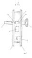
- Fig. 1a fitting in side view
- Fig.2a lock cylinder with pommels attached on both sides
- Figure 3a lock cylinder with knob attached to one side.
- Fig.1is denoted by 1 a fitting which is attached to both sides of a door, not shown.
- the actuator for opening the door of a pawl 2 and on the opposite side of a knob 3is formed on one side of the door. Depending on whether it is an outwardly or inwardly opening door, this opens in one or the other of the direction indicated by the double arrow 4 directions.
- the knob 3To open the door, the knob 3 must be turned or the pawl 2 is depressed and subsequently pressed the door in the appropriate direction or pulled.
- the actuatoris displaced in an initial gripping by the user in the opening direction relative to the fitting or to the door leaf and takes usually only after completion of limited by the stop relative movement the door leaf in the opening direction.
- the mechanical energy which acts on the actuating elementcan be forwarded in a simple manner, in order subsequently to be converted into electrical energy.
- This electrical energycan either be stored in an accumulator 6 or be made available directly to an electric lock cylinder 5.
- the pawl 2 and the knob 3are each rotatably connected to a bolt 14, the rotation causes actuation of the case, wherein in each case an electrically actuated clutch 15 is provided, so that the case can only be operated in the case of electronically detected access authorization.
- Fig.2is again denoted by 5 a lock cylinder which is provided with a knob 3 ', 3 "to each side of the lock cylinder 5.
- the knobsare in this case in the direction of Double arrow 4 arranged to be movable relative to the lock cylinder.
- a coil 7rotates in the magnetic field of a magnet 8, wherein a current is induced.
- a gear 9is provided to translate the movement. With a suitable choice of the translation in the transmission 9, the electromechanical transducer can be very well adapted to the energy requirements of each lock.
- the displacement or force conversionis selectable such that large forces act on the piezocrystal over a short path, which can be achieved by a correspondingly reducing transmission.
- the energy thus obtainedcan in turn be stored in an accumulator 6 or equal to the evaluation circuit for determining the access authorization.
- the knob 3may also be associated with a transducer (not shown)
- the knob 3"is additionally held with a tension spring 10, so that the knob 3 "is automatically returned to its original position after moving in one of the directions of the double arrow 4.
- a swinging mounting of the knob 3 "is conceivable, so that after releasing the knob due to the oscillating motion additional electrical energy is generated, which in turn can be stored in the accumulator 6.
- a lock cylinder 5is shown with a knob 3 "'fixed on one side thereof, which is again movable in the direction of the double arrow 4.
- the electromechanical transduceris here formed by a bar magnet 11 and a coil 12, the coil 12 with the knob 3 '' connected and thus in the direction of the double arrow 4 relative to the lock cylinder 5 is movable and the bar magnet 11 with the lock cylinder 5 is rigidly connected and thus immovable in this direction.
Landscapes
- Physics & Mathematics (AREA)
- Electromagnetism (AREA)
- Lock And Its Accessories (AREA)
Abstract
Description
Translated fromGermanDie Erfindung bezieht sich auf eine Vorrichtung zur Zutrittskontrolle für eine zwischen einer geöffneten und einer geschlossenen Position bewegbaren Schließeinrichtung, insbesondere Tür, Fenster od. dgl., mit einem ein Sperrglied aufweisenden Schloss, einem Handgriff zum Öffnen und Schließen der Schließeinrichtung und ggf. Betätigen des Sperrglieds, einer Empfangseinheit zum Empfangen von Identifikationsdaten eines elektronischen Schlüssels, einer Auswerteschaltung zur Feststellung der Zutrittsberechtigung auf Grund der empfangenen Identifikationsdaten, wobei das Schloss bei festgestellter Berechtigung freigegeben oder gesperrt wird, und einem mit der Bewegung des Handgriffs zusammenwirkenden Wandler zum Wandeln von mechanischer Energie in elektrische Energie.The invention relates to a device for access control for a movable between an open and a closed position closing device, in particular door, window od. Like., With a lock member having a lock, a handle for opening and closing the closing device and possibly operating the A locking member, a receiving unit for receiving identification data of an electronic key, an evaluation circuit for determining the access authorization on the basis of the received identification data, wherein the lock is released when the authorization is established or blocked, and a cooperating with the movement of the handle transducer for converting mechanical energy in electrical power.
Elektrische oder elektronische Schlösser, insbesondere Zylinderschlösser enthalten in der Regel zusätzlich zu mechanischen Verriegelungen, welche mit konventionellen Schlüsseln mechanisch sperrbar sind, oder an Stelle einer solchen mechanischen Verriegelung wenigstens einen elektromagnetisch oder motorisch betätigbaren Verriegelungsmechanismus, welcher erst nach einer elektronischen Identifikationsprüfung freigegeben wird. Die elektronische Schaltung zur Identifikationsüberprüfung wirkt hierbei meist mit geeigneten Identifikationsmedien drahtlos oder drahtgebunden zusammen, wobei in der elektronischen Auswerteschaltung eine Überprüfung erfolgt, ob das jeweilige Identifikationsmedium die Berechtigung zum Sperren des Schlosses aufweist. Nach erfolgreicher Überprüfung der Identität erfolgt dann die Freigabe des Schlosses.Electric or electronic locks, in particular cylinder locks usually contain in addition to mechanical locks, which are mechanically lockable with conventional keys, or instead of such a mechanical lock at least one electromagnetically or motor-actuated locking mechanism, which is released only after an electronic identification test. The electronic circuit for identification verification acts here mostly with suitable identification media wireless or wired together, wherein in the electronic evaluation circuit a check is made whether the respective identification medium has the authorization to lock the lock. After successful verification of the identity then the release of the lock takes place.
Zur Energieversorgung derartiger elektrischer bzw. elektronischer Verriegelungen ist in der Regel eine ständige Energieversorgung des Schlosses und oft auch des Schlüssels erforderlich und es ist daher neben dem Aufwand für eine derartige ständige Energieversorgung auch dafür Sorge zu tragen, dass eine unterbrechungsfreie Stromversorgung zur Verfügung steht, um die Funktion des Schlosses in jeder Situation aufrecht zu erhalten.For power supply of such electrical or electronic interlocks is usually a constant power supply the lock and often also the key required and it is therefore in addition to the cost of such a permanent power supply to ensure that an uninterruptible power supply is available to maintain the function of the castle in any situation.
Elektrische oder elektronische Schlösser können nun in beliebiger Weise mit Energie versorgt werden. Neben der Möglichkeit eines Netzanschlusses oder einer Stützbatterie sind auch bereits Vorschläge bekannt geworden, bei welchen das Schloss oder der Schlüssel einen Wandler zum Wandeln von mechanischer in elektrische Energie aufweist. Derartige Wandler sind beispielsweise als elektrische Generatoren ausgebildet und weisen einen Magnetkreis und eine von dessen Magnetfluss durchsetzte Induktionsspule auf, wobei der Magnetkreis oder die Induktionsspule als beweglicher Bauteil und der jeweils andere Teil als feststehender Bauteil ausgebildet ist. Dabei wird durch die Bewegung des beweglich angeordneten Bauteils im Induktionssystem eine Induktionsspannung induziert. Der bewegliche Bauteil kann beispielsweise als Schwungrad ausgebildet sein, wie dies beispielsweise aus der
Weiters ist es bekannt geworden, gesonderte Beschläge für die Energiegewinnung zu verwenden. Eine derartige Ausbildung ist beispielsweise der
Weitere Ausbildungen, bei welchen elektrische Energie aus einer Drehbewegung des Betätigungselements, wie z.B. des Türknaufes oder des Drückers, gewonnen wird, sind aus der
Weiters sind Energiegewinnungssysteme in der Tür bekannt, z.B. aus der
Die Erfindung zielt nun darauf ab, eine Zutrittskontrollvorrichtung der eingangs genannten Art dahingehend zu verbessern, dass das Wandlersystem beim Öffnen oder Schließen der Schließvorrichtung, insbesondere Tür oder Fenster, keinen merkbaren zusätzlichen Betätigungswiderstand verursacht, sodass der Benutzungskomfort verbessert wird. Weiters soll das Wandlersystem integrierbar sein, sodass der Installationsaufwand minimiert wird.The invention now aims to improve an access control device of the type mentioned in that the converter system when opening or closing the Locking device, in particular door or window, causes no appreciable additional operating resistance, so that the ease of use is improved. Furthermore, the converter system should be integrable, so that the installation effort is minimized.
Zur Lösung dieser Aufgabe ist die Zutrittskontrollvorrichtung der eingangs genannten Art erfindungsgemäß im wesentlichen derart weitergebildet, dass der Handgriff oder ein Teil desselben in einer der Öffnungs- und/oder Schließrichtung der Schließeinrichtung entsprechenden Richtung relativ zu der Schließeinrichtung bewegbar ist und mit dem Wandler derart zusammenwirkt, dass eine im Öffnungs- und/oder Schließsinn wirkende mechanische Energie in elektrische Energie gewandelt wird. Erfindungsgemäß erfolgt die Beaufschlagung des Wandlers somit auf Grund einer Bewegung des Handgriffs oder eines Teils desselben in der Öffnungs- und/oder Schließrichtung der Schließeinrichtung, insbesondere der Tür oder des Fensters, das heißt also auf Grund einer Bewegung, die beim Öffnen oder Schließen einer Tür oder eines Fensters ohnehin erforderlich ist. Die beim Öffnung- und/oder Schließvorgang auftretende mechanische Energie wird somit automatisch und unmerklich in eine entsprechende elektrische Energie umgewandelt, sodass das Wandlersystem keine gesonderten Vorgänge oder Aktivierungen erfordert. Es wird somit die beim Öffnen oder Schließen einer Tür oder eines Fensters auftretende Massenträgheit bzw. das Trägheitsmoment und auch ein Widerstand (z.B. auf Grund der Reibung der Türaufhängung) für die mechanische Betätigung des Wandlers ausgenützt, wobei der Benutzer keinen zusätzlichen Widerstand beim Öffnen oder Schließen der Tür oder des Fensters verspürt. Dadurch, dass die erforderliche mechanische Energie direkt vom Türgriff oder eines Teils desselben abgenommen wird, gelingt eine bauliche Integration des Wandlersystems in den Griff, einen Beschlag oder das Schloss, sodass ein zusätzlicher Verkabelungsaufwand entfällt.To solve this problem, the access control device of the type mentioned is inventively substantially further developed such that the handle or a part thereof in a direction corresponding to the opening and / or closing direction of the closing device is movable relative to the closing device and cooperates with the converter, that acting in the opening and / or closing mechanical energy is converted into electrical energy. According to the invention, the movement of the handle or a part thereof in the opening and / or closing direction of the closing device, in particular the door or the window, ie, due to a movement when opening or closing a door or a window is required anyway. The mechanical energy occurring during the opening and / or closing operation is thus automatically and imperceptibly converted into a corresponding electrical energy, so that the transducer system requires no separate processes or activations. Thus, the inertia or moment of inertia occurring during the opening or closing of a door or window and also a resistance (eg due to the friction of the door suspension) is utilized for the mechanical actuation of the transducer, the user not having any additional resistance when opening or closing felt the door or the window. The fact that the required mechanical energy directly from the door handle or a part thereof removed is successful, a structural integration of the transducer system in the handle, a fitting or the lock, so that no additional cabling is required.
Die Bewegungsrichtung des Handgriffs oder des Teils desselben verläuft bei einer schwenkbaren Schließeinrichtung, wie z.B. bei einer Anschlagtür im Wesentlichen normal zum Türblatt. Bei einer verschiebbaren Schließeinrichtung, wie z.B. bei einer Schiebetür hingegen verläuft Bewegungsrichtung des Handgriffs oder des Teils desselben im Wesentlichen parallel zum Türblatt.The direction of movement of the handle or the part thereof extends at a pivotable closing device, such as e.g. at a stop door substantially normal to the door leaf. In a displaceable closing device, such as e.g. in a sliding door, however, the direction of movement of the handle or the part thereof is substantially parallel to the door leaf.
Der Handgriff der Schließeinrichtung bedarf im Rahmen der Erfindung nicht notwendigerweise einer baulichen Adaptierung, sondern es muss lediglich dafür Sorge getragen werden, dass eine Beweglichkeit in Öffnungs- und/oder Schließrichtung vorhanden ist. Es können somit herkömmliche Handgriffe verwendet werden. Bevorzugt ist in diesem Zusammenhang vorgesehen, dass der Handgriff als Knauf oder Drücker ausgebildet ist.The handle of the locking device does not necessarily require a structural adaptation in the context of the invention, but only care must be taken that a mobility in the opening and / or closing direction is present. Thus, conventional handles can be used. Preferably, it is provided in this context that the handle is designed as a knob or pusher.
Der Wandler ist insbesondere als elektromechanischer Wandler ausgebildet. Eine vorteilhafte Weiterbildung sieht beispielsweise vor, dass der Wandler von einem elektrischen Generator gebildet ist. Es kann sich dabei um einen Drehgenerator oder um einen Lineargenerator handeln.The converter is designed in particular as an electromechanical converter. An advantageous development provides, for example, that the converter is formed by an electric generator. It can be a rotary generator or a linear generator.
Gemäß einer bevorzugten Weiterbildung ist vorgesehen, dass der Wandler eine Spule und einen wenigstens teilweise in den lichten Querschnitt der Spule eintauchenden Stabmagneten umfasst, wobei der Stabmagnet und die Spule relativ zueinander verschiebbar sind. Wenn der Stabmagnet gegenüber dem Durchmesser der Spule relativ lang ausgebildet ist, erhöht sich bei einer Relativbewegung zwischen Magnet und Spule die Flussänderung, sodass in der Spule eine höhere Spannung induziert wird.According to a preferred development, it is provided that the converter comprises a coil and a bar magnet which at least partially dips into the clear cross section of the coil, wherein the bar magnet and the coil are displaceable relative to each other. When the bar magnet is made relatively long with respect to the diameter of the coil, it increases During a relative movement between magnet and coil, the flux change, so that in the coil, a higher voltage is induced.
Selbstverständlich sind aber auch andere Wandlerkonfigurationen denkbar. Um bezüglich der Auswahl und der Anordnung eines geeigneten Wandlertypus möglichst wenigen Beschränkungen zu unterliegen, ist mit Vorteil vorgesehen, dass ein Getriebe zum Umsetzen der im Öffnungs- und/oder Schließsinn erfolgenden Bewegung des Handgriffs oder eines bewegbaren Teils desselben in eine Querrichtung oder in eine Rotation vorgesehen ist. Mit Hilfe des Getriebes kann gleichzeitig erforderlichenfalls eine Übersetzung, seltener auch eine Untersetzung der vom Handgriff und eines Teils desselben erfolgten Bewegung im Öffnungs- und/oder Schließsinne vorgenommen werden. Beispielsweise kann bei einem als Wegwandler ausgebildeten Getriebe ein eher kürzerer Verschiebeweg des Handgriffes in einen längeren Verschiebeweg umgesetzt werden, damit der elektrische Wandler eine ausreichende elektrische Energie liefern kann. Generell ist es nämlich wünschenswert, den Verschiebeweg des Handgriffes relativ zur Schließeinrichtung zum Antreiben des Wandlers so gering wie möglich zu halten, damit für den Benutzer im Vergleich zu einer herkömmlichen Schließeinrichtung kein wesentlicher Unterschied in der Handhabung zu merken ist. In diesem Zusammenhang ist eine Ausbildung bevorzugt, bei welcher das Getriebe eine Kraft- oder Drehmomentwandlung umfasst. Auf Grund der Massenträgheit ist bei einer entsprechenden Masse der Tür oder des Fensters oder auf Grund einer Reibung (z.B. in der Türaufhängung) für das Öffnen oder Schließen der Tür bzw. des Fensters eine relativ hohe Kraft erforderlich, die erfindungsgemäß für die Betätigung des Wandlers genützt wird, sodass ohne weiteres eine Kraft- oder Drehmomentwandlung zu Gunsten eines längeren Betätigungswegs des Wandlers erfolgen kann.Of course, other converter configurations are conceivable. In order to subject as few restrictions as possible to the selection and the arrangement of a suitable type of transducer, it is advantageously provided that a transmission for converting the movement of the handle or a movable part thereof in the opening and / or closing sense into a transverse direction or into a rotation is provided. With the help of the transmission can be made at the same time, if necessary, a translation, more rarely a reduction of the same from the handle and a part of the movement in the opening and / or closing direction. For example, in a transmission designed as a path converter, a rather shorter displacement path of the handle can be converted into a longer displacement path so that the electrical converter can supply sufficient electrical energy. In general, it is desirable to keep the displacement of the handle relative to the closing device for driving the transducer as low as possible, so that the user is not aware of any significant difference in handling compared to a conventional locking device. In this context, an embodiment is preferred in which the transmission comprises a force or torque conversion. Due to the inertia of a corresponding mass of the door or the window or due to a friction (eg in the door hanger) for opening or closing the door or the window, a relatively high force is required, the invention benefits for the operation of the converter will, so easily a force or torque conversion can be done in favor of a longer actuation path of the converter.
Mit Vorteil wirkt das Getriebe mit einem Schwungradgenerator zusammen.Advantageously, the transmission cooperates with a flywheel generator.
Gemäß einer alternativen Weiterbildung ist vorgesehen, dass der Wandler von einem Piezoelement gebildet ist. Piezoelemente sind im Rahmen der vorliegenden Erfindung mit Rücksicht auf die durch die Massenträgheit und den Reibungswiderstand der Schließeinrichtung relativ hohe erforderliche Öffnungs- bzw. Schließkraft und den anzustrebenden geringen Verschiebeweg des Handgriffs besonders bevorzugt.According to an alternative development, it is provided that the converter is formed by a piezoelectric element. Piezo elements are particularly preferred in the context of the present invention, with regard to the relatively high required by the inertia and the frictional resistance of the closing device opening or closing force and the desired low displacement of the handle.
Um nach einer Verschiebung des Handgriffs oder des bewegbaren Teils desselben eine automatische Rückholung zu erreichen, ist mit Vorteil vorgesehen, dass der Handgriff oder der bewegbare Teil desselben von seiner Ausgangslage gegen die Kraft einer Feder oder gegen eine magnetische Kraft verschiebbar ist.In order to achieve an automatic retrieval after a displacement of the handle or the movable part of the same, it is advantageously provided that the handle or the movable part of the same from its initial position against the force of a spring or against a magnetic force is displaceable.
Eine mit einem besonderen Benutzungskomfort verbundene bevorzugte Weiterbildung sieht vor, dass die Bewegung des Handgriffs oder des bewegbaren Teils desselben durch ein Dämpfungselement gedämpft ist. Besonders eine gedämpfte Rückholbewegung des Handgriffs empfindet der Benutzer als angenehm.One associated with a particular ease of use preferred development provides that the movement of the handle or the movable part of the same is damped by a damping element. Particularly a damped return movement of the handle feels the user as pleasant.
Die vom Wandler abgegebene elektrische Energie kann unmittelbar einem Schaltkreis der Zutrittskontrollvorrichtung zur Verfügung gestellt werden, beispielsweise um im Augenblick der Betätigung des Handgriffes den elektronischen Identifikationscode eines elektronischen Schlüssels abzufragen und auszuwerten. Der Wandler kann dabei bevorzugt verschiedene elektronische Bauteile des Schlosses mit elektrischer Energie versorgen, wie z.B. die Empfangseinheit, die Auswerteschaltung und/oder einen elektrischen Aktuator zum Freigeben bzw. Sperren des Schlosses. Zusätzlich oder alternativ kann der Wandler einen Energiespeicher, insbesondere einen Akkumulator oder Kondensator speisen, damit die elektrische Energie unabhängig vom Zeitpunkt der Betätigung des Handgriffes zur Verfügung steht.The electrical energy emitted by the transducer can be made available directly to a circuit of the access control device, for example, to query the electronic identification code of an electronic key at the moment of actuation of the handle and evaluate. The converter can preferably provide various electronic components of the lock with electrical energy, such as the receiving unit, the evaluation circuit and / or an electric actuator for releasing or blocking the lock. Additionally or alternatively, the converter can feed an energy store, in particular an accumulator or capacitor, so that the electrical energy is available independently of the time of actuation of the handle.
Grundsätzlich ist anzumerken, dass die erfindungsgemäße Ausbildung des Wandlersystems, bei dem die in Öffnungs-und/oder Schließrichtung erfolgte Bewegung des Hangriffes oder eines bewegbaren Teils desselben zur Energieumwandlung genützt wird, mit der herkömmlichen Funktionsweise von Wandlersystemen, bei der das Verschwenken des Handgriffes für die Energieumwandlung genützt wird, kombiniert werden kann. Es kann daher sowohl die auf Grund des Verschwenkens bzw. Rotierens des Handgriffes eingebrachte mechanische Energie als auch die auf Grund des Drückens bzw. Ziehens des Handgriffes im Sinne einer Öffnungs- bzw. Schließbewegung eingebrachte mechanische Energie mit Hilfe wenigstens eines geeigneten Wandlers in elektrische Energie umgewandelt werden.Basically, it should be noted that the inventive construction of the transducer system in which the movement in the opening and / or closing direction of the handle handle or a movable part thereof is used for energy conversion, with the conventional operation of transducer systems, in which the pivoting of the handle for the Energy conversion can be combined. It can therefore both the introduced due to the pivoting or rotating the handle mechanical energy and the introduced due to the pressing or pulling of the handle in the sense of an opening or closing movement mechanical energy using at least one suitable transducer into electrical energy become.
Die Erfindung wird nachfolgend anhand von in der Zeichnung schematisch dargestellten Ausführungsbeispielen erläutert. In dieser zeigen
In
Auf der einen Seite der Tür ist das Betätigungselement zum Öffnen der Tür von einer Klinke 2 und auf der gegenüberliegenden Seite von einem Knauf 3 gebildet. Je nachdem, ob es sich um eine nach außen oder nach innen öffnende Tür handelt, öffnet sich diese in die eine oder die andere der mit dem Doppelpfeil 4 bezeichneten Richtungen. Zum Öffnen der Türe muss der Knauf 3 gedreht bzw. die Klinke 2 heruntergedrückt werden und im Anschluss die Türe in die entsprechende Richtung gedrückt bzw. gezogen werden. Das Betätigungselement wird bei einem anfänglichen Ergreifen durch den Benutzer in Öffnungsrichtung relativ zum Beschlag bzw. zum Türblatt verschoben und nimmt in der Regel erst nach Beendigung der durch den Anschlag begrenzten Relativbewegung das Türblatt in Öffnungsrichtung mit. Dadurch, dass das Betätigungselement in Richtung des Doppelpfeils 4 beweglich angeordnet ist, kann die mechanische Energie, die auf das Betätigungselement einwirkt, in einfacher Weise weitergeleitet werden, um in weiterer Folge in elektrische Energie umgewandelt zu werden. Diese elektrische Energie kann entweder in einen Akkumulator 6 gespeichert werden oder unmittelbar einem elektrischen Schließzylinder 5 zur Verfügung gestellt werden.On one side of the door, the actuator for opening the door of a
Die Klinke 2 und der Knauf 3 sind jeweils mit einem Bolzen 14 drehfest verbunden, dessen Drehung eine Betätigung der Falle bewirkt, wobei jeweils eine elektrisch betätigbare Kupplung 15 vorgesehen ist, sodass die Falle nur im Falle der elektronisch festgestellten Zutrittsberechtigung betätigt werden kann.The
In
In
Claims (12)
Translated fromGermanApplications Claiming Priority (1)
| Application Number | Priority Date | Filing Date | Title |
|---|---|---|---|
| AT5112010AAT509465B1 (en) | 2010-03-30 | 2010-03-30 | APPARATUS FOR ACCESS CONTROL WITH ELECTROMECHANICAL CONVERTER |
Publications (3)
| Publication Number | Publication Date |
|---|---|
| EP2372052A2true EP2372052A2 (en) | 2011-10-05 |
| EP2372052A3 EP2372052A3 (en) | 2014-06-25 |
| EP2372052B1 EP2372052B1 (en) | 2015-12-16 |
Family
ID=44279137
Family Applications (1)
| Application Number | Title | Priority Date | Filing Date |
|---|---|---|---|
| EP11450022.6ANot-in-forceEP2372052B1 (en) | 2010-03-30 | 2011-02-15 | Closing device comprising an access control device with electromechanical converter |
Country Status (3)
| Country | Link |
|---|---|
| EP (1) | EP2372052B1 (en) |
| AT (1) | AT509465B1 (en) |
| ES (1) | ES2559240T3 (en) |
Cited By (7)
| Publication number | Priority date | Publication date | Assignee | Title |
|---|---|---|---|---|
| EP2568101A3 (en)* | 2011-09-12 | 2014-04-30 | Assa Abloy Sicherheitstechnik GmbH | Knob cylinder |
| DE102014111413B3 (en)* | 2014-08-11 | 2015-09-17 | ASTRA Gesellschaft für Asset Management mbH & Co. KG | Lock cylinder arrangement |
| CN106849310A (en)* | 2017-02-28 | 2017-06-13 | 珠海格力电器股份有限公司 | Knob self-powered method, device and system and knob wire controller |
| CN107386789A (en)* | 2017-08-09 | 2017-11-24 | 浙江金凯德智能家居有限公司 | A kind of intelligent door lock |
| CN112955619A (en)* | 2018-11-16 | 2021-06-11 | 欧美克锯齿股份公司 | Lock head for driving mechanism |
| CN115556631A (en)* | 2022-10-21 | 2023-01-03 | 四川智锂智慧能源科技有限公司 | Buffering shock-absorbing structure and vehicle |
| AT525744A4 (en)* | 2022-03-03 | 2023-07-15 | Evva Sicherheitstechnologie | locking device |
Families Citing this family (2)
| Publication number | Priority date | Publication date | Assignee | Title |
|---|---|---|---|---|
| RU2616907C1 (en)* | 2016-04-25 | 2017-04-18 | Никишин ГмбХ | Door handle assembly |
| CN107060499A (en)* | 2017-04-24 | 2017-08-18 | 浙江凯迪仕实业有限公司 | Internet of things fingerprint lock |
Citations (6)
| Publication number | Priority date | Publication date | Assignee | Title |
|---|---|---|---|---|
| US3733861A (en) | 1972-01-19 | 1973-05-22 | Recognition Devices | Electronic recognition door lock |
| EP0462316A1 (en) | 1990-06-20 | 1991-12-27 | Karl Fliether GmbH & Co. KG | Double cylinder lock with electric locking means |
| FR2728613A1 (en) | 1994-12-23 | 1996-06-28 | Clapier Bernard | Autonomous code operated electronic door lock |
| EP1039074A1 (en) | 1999-03-23 | 2000-09-27 | EVVA-Werk Spezialerzeugung von Zylinder- und Sicherheitsschlössern Gesellschaft m.b.H. & Co. Kommanditgesellschaft | Key for actuating electronic secured locks |
| DE102004052802A1 (en) | 2004-10-26 | 2006-04-27 | Kries-Energietechnik Gmbh & Co.Kg | Operating system for motor vehicle/building door locking system, has generator whose shaft is rotated, when transponder unit rotates, to generate energy which is converted to DC voltage and supplied to authentication verification unit |
| DE102007032855A1 (en) | 2007-07-12 | 2009-01-22 | Karl-Heinz Bosch | Electrical energy producing method for operating e.g. electrical lock of door, involves converting kinetic energy arising at mobile component into electrical energy by energy converter, and producing electrical energy directly on component |
Family Cites Families (12)
| Publication number | Priority date | Publication date | Assignee | Title |
|---|---|---|---|---|
| US3984707A (en)* | 1973-07-13 | 1976-10-05 | Mcclintock Richard D | Spring return linear signal generator |
| DE19724085C1 (en)* | 1997-06-07 | 1998-10-29 | Kiekert Ag | Vehicle door lock with external door handle and key reception |
| DE19829927C2 (en)* | 1998-07-04 | 2001-01-25 | Drumm Sicherheit Gmbh | Electronic door fitting |
| EP1070814A1 (en)* | 1999-07-23 | 2001-01-24 | Sesam Elektronische Sicherheitssysteme GmbH | Electrically unlockable lockmechanism |
| DE10038152A1 (en)* | 2000-08-04 | 2002-02-14 | Kiekert Ag | Energy storage and/or conversion device has energy storage device made of ferroelectric or piezoelectric material, with shape memory metal alloy or spring tensioned by electric motor |
| DE10052640A1 (en)* | 2000-10-24 | 2002-05-02 | Bayerische Motoren Werke Ag | Door handle with damping unit esp. at motor vehicle door which is adjustable for opening door lock manually against force or return spring from normal in lock open position and damping |
| DE20114838U1 (en)* | 2001-09-08 | 2001-12-13 | Drumm GmbH, 97337 Dettelbach | Generator drive for electrical or electronic locking systems |
| JP2004108035A (en)* | 2002-09-19 | 2004-04-08 | Tokai Rika Co Ltd | Door opening and closing device |
| DE102004041518A1 (en)* | 2004-03-12 | 2005-09-29 | Dom-Sicherheitstechnik Gmbh & Co. Kg | Cylinder for a lock has operating knob that is only coupled to operate the lock on receipt of a valid wireless signal from a transponder |
| DE102006041589A1 (en)* | 2005-09-15 | 2007-03-22 | Marquardt Gmbh | Electrical door lock for use in e.g. car, has generators that stand in connection with electrical actuator such that energy is produced by generators for energy supply of actuator during failure of main power supply energy |
| US7605482B2 (en)* | 2007-01-08 | 2009-10-20 | Veryst Engineering Llc | Method and apparatus for energy harvesting using energy storage and release |
| DE102008027160A1 (en)* | 2008-06-06 | 2009-12-10 | Conti Temic Microelectronic Gmbh | Electronic locking system for locking vehicle, has energy generating unit electromechanically and/or electromagnetically connected to manually operable actuating unit, and generating electrical energy during operation of actuating unit |
- 2010
- 2010-03-30ATAT5112010Apatent/AT509465B1/ennot_activeIP Right Cessation
- 2011
- 2011-02-15ESES11450022.6Tpatent/ES2559240T3/enactiveActive
- 2011-02-15EPEP11450022.6Apatent/EP2372052B1/ennot_activeNot-in-force
Patent Citations (6)
| Publication number | Priority date | Publication date | Assignee | Title |
|---|---|---|---|---|
| US3733861A (en) | 1972-01-19 | 1973-05-22 | Recognition Devices | Electronic recognition door lock |
| EP0462316A1 (en) | 1990-06-20 | 1991-12-27 | Karl Fliether GmbH & Co. KG | Double cylinder lock with electric locking means |
| FR2728613A1 (en) | 1994-12-23 | 1996-06-28 | Clapier Bernard | Autonomous code operated electronic door lock |
| EP1039074A1 (en) | 1999-03-23 | 2000-09-27 | EVVA-Werk Spezialerzeugung von Zylinder- und Sicherheitsschlössern Gesellschaft m.b.H. & Co. Kommanditgesellschaft | Key for actuating electronic secured locks |
| DE102004052802A1 (en) | 2004-10-26 | 2006-04-27 | Kries-Energietechnik Gmbh & Co.Kg | Operating system for motor vehicle/building door locking system, has generator whose shaft is rotated, when transponder unit rotates, to generate energy which is converted to DC voltage and supplied to authentication verification unit |
| DE102007032855A1 (en) | 2007-07-12 | 2009-01-22 | Karl-Heinz Bosch | Electrical energy producing method for operating e.g. electrical lock of door, involves converting kinetic energy arising at mobile component into electrical energy by energy converter, and producing electrical energy directly on component |
Cited By (11)
| Publication number | Priority date | Publication date | Assignee | Title |
|---|---|---|---|---|
| EP2568101A3 (en)* | 2011-09-12 | 2014-04-30 | Assa Abloy Sicherheitstechnik GmbH | Knob cylinder |
| DE102014111413B3 (en)* | 2014-08-11 | 2015-09-17 | ASTRA Gesellschaft für Asset Management mbH & Co. KG | Lock cylinder arrangement |
| EP2985398A1 (en) | 2014-08-11 | 2016-02-17 | ASTRA Gesellschaft für Asset Management mbH & Co. KG | Lock-cylinder assembly |
| CN106849310A (en)* | 2017-02-28 | 2017-06-13 | 珠海格力电器股份有限公司 | Knob self-powered method, device and system and knob wire controller |
| CN106849310B (en)* | 2017-02-28 | 2023-10-03 | 珠海格力电器股份有限公司 | Knob self-powered method, device and system and knob wire controller |
| CN107386789A (en)* | 2017-08-09 | 2017-11-24 | 浙江金凯德智能家居有限公司 | A kind of intelligent door lock |
| CN112955619A (en)* | 2018-11-16 | 2021-06-11 | 欧美克锯齿股份公司 | Lock head for driving mechanism |
| CN112955619B (en)* | 2018-11-16 | 2023-04-25 | 欧美克锯齿股份公司 | Locking head for drive mechanism |
| AT525744A4 (en)* | 2022-03-03 | 2023-07-15 | Evva Sicherheitstechnologie | locking device |
| AT525744B1 (en)* | 2022-03-03 | 2023-07-15 | Evva Sicherheitstechnologie | locking device |
| CN115556631A (en)* | 2022-10-21 | 2023-01-03 | 四川智锂智慧能源科技有限公司 | Buffering shock-absorbing structure and vehicle |
Also Published As
| Publication number | Publication date |
|---|---|
| ES2559240T3 (en) | 2016-02-11 |
| EP2372052A3 (en) | 2014-06-25 |
| AT509465B1 (en) | 2011-09-15 |
| EP2372052B1 (en) | 2015-12-16 |
| AT509465A4 (en) | 2011-09-15 |
Similar Documents
| Publication | Publication Date | Title |
|---|---|---|
| EP2372052B1 (en) | Closing device comprising an access control device with electromechanical converter | |
| EP1292747A1 (en) | Self-locking latch and a locking system equipped with said latch | |
| WO2004057137A1 (en) | Locking device | |
| DE102015115221A1 (en) | Handle of a motor vehicle door handle | |
| DE102008063061A1 (en) | Actuating device for electronic door lock, has coupling pins engaged in coupling recess in unlock condition, and torque proof connection between outer wall and coupling arrangement supported by engagement of coupling pins in recess | |
| DE202009006211U1 (en) | Device for actuating the locking mechanism of a lock | |
| DE19848286B4 (en) | Coupling assembly for an electromechanical locking system | |
| DE102016104779A1 (en) | Anti-panic push rod with drive device | |
| DE202015101504U1 (en) | locking system | |
| EP2175166B1 (en) | Locking device | |
| EP2133497B1 (en) | Vehicle door lock | |
| DE10324690A1 (en) | Method for remotely operating a cylinder lock has two separable sections which may be locked together electrically or by means of a key | |
| DE19519789B4 (en) | Lock with lock cylinder | |
| DE19924458B4 (en) | Motor vehicle door locking device | |
| DE102010028647B3 (en) | Lock for use with access control device for door, has lock mechanism controlling latch bolt or bar and actuating handle which is coupled with lock mechanism for actuating latch bolt or bar by pre-loaded spring | |
| DE102011118892A1 (en) | lock assembly | |
| DE102022132983B3 (en) | Door opener | |
| EP1662076B1 (en) | Coupling device for a locking arrangement | |
| WO2015144535A1 (en) | Lock for door or window | |
| DE60121495T2 (en) | locking device | |
| DE102009018471A1 (en) | Lock box with piezomotor | |
| EP1070814A1 (en) | Electrically unlockable lockmechanism | |
| EP1170443A1 (en) | Electromotive drive for a lock | |
| DE102007042574A1 (en) | Lock for use in public and commercially used areas, for locking door, has safety catch movable from locking position to opening position by actuator that is arranged between spindle nut and electric motor | |
| DE102015000604A1 (en) | Locking device for a door or a window |
Legal Events
| Date | Code | Title | Description |
|---|---|---|---|
| PUAI | Public reference made under article 153(3) epc to a published international application that has entered the european phase | Free format text:ORIGINAL CODE: 0009012 | |
| AK | Designated contracting states | Kind code of ref document:A2 Designated state(s):AL AT BE BG CH CY CZ DE DK EE ES FI FR GB GR HR HU IE IS IT LI LT LU LV MC MK MT NL NO PL PT RO RS SE SI SK SM TR | |
| AX | Request for extension of the european patent | Extension state:BA ME | |
| PUAL | Search report despatched | Free format text:ORIGINAL CODE: 0009013 | |
| AK | Designated contracting states | Kind code of ref document:A3 Designated state(s):AL AT BE BG CH CY CZ DE DK EE ES FI FR GB GR HR HU IE IS IT LI LT LU LV MC MK MT NL NO PL PT RO RS SE SI SK SM TR | |
| AX | Request for extension of the european patent | Extension state:BA ME | |
| RIC1 | Information provided on ipc code assigned before grant | Ipc:E05B 47/06 20060101ALI20140520BHEP Ipc:E05B 15/02 20060101ALI20140520BHEP Ipc:E05B 47/00 20060101ALI20140520BHEP Ipc:E05B 1/00 20060101AFI20140520BHEP | |
| RIN1 | Information on inventor provided before grant (corrected) | Inventor name:ENNE, REINHARD | |
| RIN1 | Information on inventor provided before grant (corrected) | Inventor name:ENNE, J. REINHARD | |
| 17P | Request for examination filed | Effective date:20150105 | |
| RBV | Designated contracting states (corrected) | Designated state(s):AL AT BE BG CH CY CZ DE DK EE ES FI FR GB GR HR HU IE IS IT LI LT LU LV MC MK MT NL NO PL PT RO RS SE SI SK SM TR | |
| 17Q | First examination report despatched | Effective date:20150224 | |
| GRAP | Despatch of communication of intention to grant a patent | Free format text:ORIGINAL CODE: EPIDOSNIGR1 | |
| INTG | Intention to grant announced | Effective date:20150623 | |
| GRAS | Grant fee paid | Free format text:ORIGINAL CODE: EPIDOSNIGR3 | |
| GRAA | (expected) grant | Free format text:ORIGINAL CODE: 0009210 | |
| AK | Designated contracting states | Kind code of ref document:B1 Designated state(s):AL AT BE BG CH CY CZ DE DK EE ES FI FR GB GR HR HU IE IS IT LI LT LU LV MC MK MT NL NO PL PT RO RS SE SI SK SM TR | |
| REG | Reference to a national code | Ref country code:GB Ref legal event code:FG4D Free format text:NOT ENGLISH | |
| REG | Reference to a national code | Ref country code:CH Ref legal event code:EP Ref country code:CH Ref legal event code:NV Representative=s name:OK PAT AG PATENTE MARKEN LIZENZEN, CH | |
| REG | Reference to a national code | Ref country code:IE Ref legal event code:FG4D Free format text:LANGUAGE OF EP DOCUMENT: GERMAN | |
| REG | Reference to a national code | Ref country code:AT Ref legal event code:REF Ref document number:765644 Country of ref document:AT Kind code of ref document:T Effective date:20160115 | |
| REG | Reference to a national code | Ref country code:DE Ref legal event code:R096 Ref document number:502011008505 Country of ref document:DE | |
| REG | Reference to a national code | Ref country code:SE Ref legal event code:TRGR | |
| REG | Reference to a national code | Ref country code:ES Ref legal event code:FG2A Ref document number:2559240 Country of ref document:ES Kind code of ref document:T3 Effective date:20160211 | |
| REG | Reference to a national code | Ref country code:FR Ref legal event code:PLFP Year of fee payment:6 | |
| REG | Reference to a national code | Ref country code:NL Ref legal event code:FP | |
| REG | Reference to a national code | Ref country code:LT Ref legal event code:MG4D | |
| PG25 | Lapsed in a contracting state [announced via postgrant information from national office to epo] | Ref country code:NO Free format text:LAPSE BECAUSE OF FAILURE TO SUBMIT A TRANSLATION OF THE DESCRIPTION OR TO PAY THE FEE WITHIN THE PRESCRIBED TIME-LIMIT Effective date:20160316 Ref country code:LT Free format text:LAPSE BECAUSE OF FAILURE TO SUBMIT A TRANSLATION OF THE DESCRIPTION OR TO PAY THE FEE WITHIN THE PRESCRIBED TIME-LIMIT Effective date:20151216 Ref country code:HR Free format text:LAPSE BECAUSE OF FAILURE TO SUBMIT A TRANSLATION OF THE DESCRIPTION OR TO PAY THE FEE WITHIN THE PRESCRIBED TIME-LIMIT Effective date:20151216 | |
| PG25 | Lapsed in a contracting state [announced via postgrant information from national office to epo] | Ref country code:RS Free format text:LAPSE BECAUSE OF FAILURE TO SUBMIT A TRANSLATION OF THE DESCRIPTION OR TO PAY THE FEE WITHIN THE PRESCRIBED TIME-LIMIT Effective date:20151216 Ref country code:GR Free format text:LAPSE BECAUSE OF FAILURE TO SUBMIT A TRANSLATION OF THE DESCRIPTION OR TO PAY THE FEE WITHIN THE PRESCRIBED TIME-LIMIT Effective date:20160317 Ref country code:LV Free format text:LAPSE BECAUSE OF FAILURE TO SUBMIT A TRANSLATION OF THE DESCRIPTION OR TO PAY THE FEE WITHIN THE PRESCRIBED TIME-LIMIT Effective date:20151216 Ref country code:BE Free format text:LAPSE BECAUSE OF NON-PAYMENT OF DUE FEES Effective date:20160229 Ref country code:FI Free format text:LAPSE BECAUSE OF FAILURE TO SUBMIT A TRANSLATION OF THE DESCRIPTION OR TO PAY THE FEE WITHIN THE PRESCRIBED TIME-LIMIT Effective date:20151216 | |
| PG25 | Lapsed in a contracting state [announced via postgrant information from national office to epo] | Ref country code:CZ Free format text:LAPSE BECAUSE OF FAILURE TO SUBMIT A TRANSLATION OF THE DESCRIPTION OR TO PAY THE FEE WITHIN THE PRESCRIBED TIME-LIMIT Effective date:20151216 Ref country code:IT Free format text:LAPSE BECAUSE OF FAILURE TO SUBMIT A TRANSLATION OF THE DESCRIPTION OR TO PAY THE FEE WITHIN THE PRESCRIBED TIME-LIMIT Effective date:20151216 | |
| PG25 | Lapsed in a contracting state [announced via postgrant information from national office to epo] | Ref country code:PT Free format text:LAPSE BECAUSE OF FAILURE TO SUBMIT A TRANSLATION OF THE DESCRIPTION OR TO PAY THE FEE WITHIN THE PRESCRIBED TIME-LIMIT Effective date:20160418 Ref country code:RO Free format text:LAPSE BECAUSE OF FAILURE TO SUBMIT A TRANSLATION OF THE DESCRIPTION OR TO PAY THE FEE WITHIN THE PRESCRIBED TIME-LIMIT Effective date:20151216 Ref country code:SK Free format text:LAPSE BECAUSE OF FAILURE TO SUBMIT A TRANSLATION OF THE DESCRIPTION OR TO PAY THE FEE WITHIN THE PRESCRIBED TIME-LIMIT Effective date:20151216 Ref country code:IS Free format text:LAPSE BECAUSE OF FAILURE TO SUBMIT A TRANSLATION OF THE DESCRIPTION OR TO PAY THE FEE WITHIN THE PRESCRIBED TIME-LIMIT Effective date:20160416 Ref country code:SM Free format text:LAPSE BECAUSE OF FAILURE TO SUBMIT A TRANSLATION OF THE DESCRIPTION OR TO PAY THE FEE WITHIN THE PRESCRIBED TIME-LIMIT Effective date:20151216 Ref country code:EE Free format text:LAPSE BECAUSE OF FAILURE TO SUBMIT A TRANSLATION OF THE DESCRIPTION OR TO PAY THE FEE WITHIN THE PRESCRIBED TIME-LIMIT Effective date:20151216 | |
| REG | Reference to a national code | Ref country code:DE Ref legal event code:R097 Ref document number:502011008505 Country of ref document:DE | |
| PG25 | Lapsed in a contracting state [announced via postgrant information from national office to epo] | Ref country code:MC Free format text:LAPSE BECAUSE OF FAILURE TO SUBMIT A TRANSLATION OF THE DESCRIPTION OR TO PAY THE FEE WITHIN THE PRESCRIBED TIME-LIMIT Effective date:20151216 Ref country code:LU Free format text:LAPSE BECAUSE OF FAILURE TO SUBMIT A TRANSLATION OF THE DESCRIPTION OR TO PAY THE FEE WITHIN THE PRESCRIBED TIME-LIMIT Effective date:20160215 | |
| PLBE | No opposition filed within time limit | Free format text:ORIGINAL CODE: 0009261 | |
| STAA | Information on the status of an ep patent application or granted ep patent | Free format text:STATUS: NO OPPOSITION FILED WITHIN TIME LIMIT | |
| PG25 | Lapsed in a contracting state [announced via postgrant information from national office to epo] | Ref country code:DK Free format text:LAPSE BECAUSE OF FAILURE TO SUBMIT A TRANSLATION OF THE DESCRIPTION OR TO PAY THE FEE WITHIN THE PRESCRIBED TIME-LIMIT Effective date:20151216 Ref country code:PL Free format text:LAPSE BECAUSE OF FAILURE TO SUBMIT A TRANSLATION OF THE DESCRIPTION OR TO PAY THE FEE WITHIN THE PRESCRIBED TIME-LIMIT Effective date:20151216 | |
| 26N | No opposition filed | Effective date:20160919 | |
| REG | Reference to a national code | Ref country code:IE Ref legal event code:MM4A | |
| PG25 | Lapsed in a contracting state [announced via postgrant information from national office to epo] | Ref country code:IE Free format text:LAPSE BECAUSE OF NON-PAYMENT OF DUE FEES Effective date:20160215 | |
| REG | Reference to a national code | Ref country code:FR Ref legal event code:PLFP Year of fee payment:7 | |
| PG25 | Lapsed in a contracting state [announced via postgrant information from national office to epo] | Ref country code:SI Free format text:LAPSE BECAUSE OF FAILURE TO SUBMIT A TRANSLATION OF THE DESCRIPTION OR TO PAY THE FEE WITHIN THE PRESCRIBED TIME-LIMIT Effective date:20151216 | |
| REG | Reference to a national code | Ref country code:AT Ref legal event code:MM01 Ref document number:765644 Country of ref document:AT Kind code of ref document:T Effective date:20160215 | |
| PG25 | Lapsed in a contracting state [announced via postgrant information from national office to epo] | Ref country code:AT Free format text:LAPSE BECAUSE OF NON-PAYMENT OF DUE FEES Effective date:20160215 | |
| PG25 | Lapsed in a contracting state [announced via postgrant information from national office to epo] | Ref country code:MT Free format text:LAPSE BECAUSE OF FAILURE TO SUBMIT A TRANSLATION OF THE DESCRIPTION OR TO PAY THE FEE WITHIN THE PRESCRIBED TIME-LIMIT Effective date:20151216 | |
| REG | Reference to a national code | Ref country code:FR Ref legal event code:PLFP Year of fee payment:8 | |
| PGFP | Annual fee paid to national office [announced via postgrant information from national office to epo] | Ref country code:NL Payment date:20180226 Year of fee payment:8 | |
| PGFP | Annual fee paid to national office [announced via postgrant information from national office to epo] | Ref country code:CH Payment date:20180227 Year of fee payment:8 Ref country code:DE Payment date:20180227 Year of fee payment:8 Ref country code:GB Payment date:20180227 Year of fee payment:8 Ref country code:ES Payment date:20180301 Year of fee payment:8 | |
| PG25 | Lapsed in a contracting state [announced via postgrant information from national office to epo] | Ref country code:HU Free format text:LAPSE BECAUSE OF FAILURE TO SUBMIT A TRANSLATION OF THE DESCRIPTION OR TO PAY THE FEE WITHIN THE PRESCRIBED TIME-LIMIT; INVALID AB INITIO Effective date:20110215 Ref country code:CY Free format text:LAPSE BECAUSE OF FAILURE TO SUBMIT A TRANSLATION OF THE DESCRIPTION OR TO PAY THE FEE WITHIN THE PRESCRIBED TIME-LIMIT Effective date:20151216 | |
| PGFP | Annual fee paid to national office [announced via postgrant information from national office to epo] | Ref country code:SE Payment date:20180227 Year of fee payment:8 Ref country code:FR Payment date:20180227 Year of fee payment:8 | |
| PG25 | Lapsed in a contracting state [announced via postgrant information from national office to epo] | Ref country code:MK Free format text:LAPSE BECAUSE OF FAILURE TO SUBMIT A TRANSLATION OF THE DESCRIPTION OR TO PAY THE FEE WITHIN THE PRESCRIBED TIME-LIMIT Effective date:20151216 Ref country code:TR Free format text:LAPSE BECAUSE OF FAILURE TO SUBMIT A TRANSLATION OF THE DESCRIPTION OR TO PAY THE FEE WITHIN THE PRESCRIBED TIME-LIMIT Effective date:20151216 | |
| PG25 | Lapsed in a contracting state [announced via postgrant information from national office to epo] | Ref country code:BG Free format text:LAPSE BECAUSE OF FAILURE TO SUBMIT A TRANSLATION OF THE DESCRIPTION OR TO PAY THE FEE WITHIN THE PRESCRIBED TIME-LIMIT Effective date:20151216 | |
| PG25 | Lapsed in a contracting state [announced via postgrant information from national office to epo] | Ref country code:AL Free format text:LAPSE BECAUSE OF FAILURE TO SUBMIT A TRANSLATION OF THE DESCRIPTION OR TO PAY THE FEE WITHIN THE PRESCRIBED TIME-LIMIT Effective date:20151216 | |
| REG | Reference to a national code | Ref country code:DE Ref legal event code:R119 Ref document number:502011008505 Country of ref document:DE | |
| REG | Reference to a national code | Ref country code:CH Ref legal event code:PL | |
| REG | Reference to a national code | Ref country code:SE Ref legal event code:EUG | |
| REG | Reference to a national code | Ref country code:NL Ref legal event code:MM Effective date:20190301 | |
| GBPC | Gb: european patent ceased through non-payment of renewal fee | Effective date:20190215 | |
| PG25 | Lapsed in a contracting state [announced via postgrant information from national office to epo] | Ref country code:SE Free format text:LAPSE BECAUSE OF NON-PAYMENT OF DUE FEES Effective date:20190216 | |
| PG25 | Lapsed in a contracting state [announced via postgrant information from national office to epo] | Ref country code:LI Free format text:LAPSE BECAUSE OF NON-PAYMENT OF DUE FEES Effective date:20190228 Ref country code:CH Free format text:LAPSE BECAUSE OF NON-PAYMENT OF DUE FEES Effective date:20190228 | |
| PG25 | Lapsed in a contracting state [announced via postgrant information from national office to epo] | Ref country code:NL Free format text:LAPSE BECAUSE OF NON-PAYMENT OF DUE FEES Effective date:20190301 Ref country code:DE Free format text:LAPSE BECAUSE OF NON-PAYMENT OF DUE FEES Effective date:20190903 Ref country code:GB Free format text:LAPSE BECAUSE OF NON-PAYMENT OF DUE FEES Effective date:20190215 | |
| PG25 | Lapsed in a contracting state [announced via postgrant information from national office to epo] | Ref country code:FR Free format text:LAPSE BECAUSE OF NON-PAYMENT OF DUE FEES Effective date:20190228 | |
| REG | Reference to a national code | Ref country code:ES Ref legal event code:FD2A Effective date:20200330 | |
| PG25 | Lapsed in a contracting state [announced via postgrant information from national office to epo] | Ref country code:ES Free format text:LAPSE BECAUSE OF NON-PAYMENT OF DUE FEES Effective date:20190216 |