EP2371527B1 - Device and method for manufacturing (tobacco) bags - Google Patents
Device and method for manufacturing (tobacco) bagsDownload PDFInfo
- Publication number
- EP2371527B1 EP2371527B1EP11002623.4AEP11002623AEP2371527B1EP 2371527 B1EP2371527 B1EP 2371527B1EP 11002623 AEP11002623 AEP 11002623AEP 2371527 B1EP2371527 B1EP 2371527B1
- Authority
- EP
- European Patent Office
- Prior art keywords
- bag
- hook
- loop
- strips
- strip
- Prior art date
- Legal status (The legal status is an assumption and is not a legal conclusion. Google has not performed a legal analysis and makes no representation as to the accuracy of the status listed.)
- Not-in-force
Links
- 241000208125NicotianaSpecies0.000titleclaimsdescription45
- 235000002637Nicotiana tabacumNutrition0.000titleclaimsdescription45
- 238000000034methodMethods0.000titleclaimsdescription21
- 238000004519manufacturing processMethods0.000titleclaimsdescription12
- 239000000463materialSubstances0.000claimsdescription51
- 239000000853adhesiveSubstances0.000claimsdescription22
- 238000012546transferMethods0.000claimsdescription22
- 238000005520cutting processMethods0.000claimsdescription17
- 238000000576coating methodMethods0.000claimsdescription14
- 239000011248coating agentSubstances0.000claimsdescription11
- 239000003292glueSubstances0.000claimsdescription7
- 230000003313weakening effectEffects0.000claimsdescription7
- 238000003825pressingMethods0.000claimsdescription5
- 238000004026adhesive bondingMethods0.000claimsdescription4
- 230000007246mechanismEffects0.000claims16
- 239000000109continuous materialSubstances0.000claims1
- 230000001070adhesive effectEffects0.000description17
- 238000000926separation methodMethods0.000description8
- 238000004806packaging method and processMethods0.000description4
- 239000011888foilSubstances0.000description3
- 210000000056organAnatomy0.000description3
- 229920001296polysiloxanePolymers0.000description3
- 238000007789sealingMethods0.000description3
- 238000004804windingMethods0.000description3
- 241000282472Canis lupus familiarisSpecies0.000description2
- 230000000694effectsEffects0.000description2
- 238000012856packingMethods0.000description2
- 239000004447silicone coatingSubstances0.000description2
- 240000005528Arctium lappaSpecies0.000description1
- 235000003130Arctium lappaNutrition0.000description1
- 235000008078Arctium minusNutrition0.000description1
- 244000061176Nicotiana tabacumSpecies0.000description1
- 230000005540biological transmissionEffects0.000description1
- 230000015572biosynthetic processEffects0.000description1
- 230000006835compressionEffects0.000description1
- 238000007906compressionMethods0.000description1
- 125000004122cyclic groupChemical group0.000description1
- 238000013461designMethods0.000description1
- 239000000428dustSubstances0.000description1
- 239000010408filmSubstances0.000description1
- 230000002093peripheral effectEffects0.000description1
- 239000002243precursorSubstances0.000description1
- 238000002360preparation methodMethods0.000description1
- 238000012545processingMethods0.000description1
- 238000007493shaping processMethods0.000description1
- 239000010409thin filmSubstances0.000description1
- 238000012549trainingMethods0.000description1
Images


Classifications
- B—PERFORMING OPERATIONS; TRANSPORTING
- B65—CONVEYING; PACKING; STORING; HANDLING THIN OR FILAMENTARY MATERIAL
- B65D—CONTAINERS FOR STORAGE OR TRANSPORT OF ARTICLES OR MATERIALS, e.g. BAGS, BARRELS, BOTTLES, BOXES, CANS, CARTONS, CRATES, DRUMS, JARS, TANKS, HOPPERS, FORWARDING CONTAINERS; ACCESSORIES, CLOSURES, OR FITTINGS THEREFOR; PACKAGING ELEMENTS; PACKAGES
- B65D33/00—Details of, or accessories for, sacks or bags
- B65D33/16—End- or aperture-closing arrangements or devices
- B65D33/24—End- or aperture-closing arrangements or devices using self-locking integral or attached closure elements, e.g. flaps
- B—PERFORMING OPERATIONS; TRANSPORTING
- B31—MAKING ARTICLES OF PAPER, CARDBOARD OR MATERIAL WORKED IN A MANNER ANALOGOUS TO PAPER; WORKING PAPER, CARDBOARD OR MATERIAL WORKED IN A MANNER ANALOGOUS TO PAPER
- B31B—MAKING CONTAINERS OF PAPER, CARDBOARD OR MATERIAL WORKED IN A MANNER ANALOGOUS TO PAPER
- B31B70/00—Making flexible containers, e.g. envelopes or bags
- B31B70/74—Auxiliary operations
- B31B70/81—Forming or attaching accessories, e.g. opening devices, closures or tear strings
- B31B70/812—Applying patches, strips or strings on sheets or webs
- B31B70/8123—Applying strips
- B—PERFORMING OPERATIONS; TRANSPORTING
- B65—CONVEYING; PACKING; STORING; HANDLING THIN OR FILAMENTARY MATERIAL
- B65D—CONTAINERS FOR STORAGE OR TRANSPORT OF ARTICLES OR MATERIALS, e.g. BAGS, BARRELS, BOTTLES, BOXES, CANS, CARTONS, CRATES, DRUMS, JARS, TANKS, HOPPERS, FORWARDING CONTAINERS; ACCESSORIES, CLOSURES, OR FITTINGS THEREFOR; PACKAGING ELEMENTS; PACKAGES
- B65D2313/00—Connecting or fastening means
- B65D2313/02—Connecting or fastening means of hook-and-loop type
Definitions
- the inventionrelates to a method for producing (tobacco) bag packages with Velcro pieces for fixing a tab in the closed position and the other features in the preamble of claim 1. Furthermore, the invention relates to a device for carrying out the method.
- Pouches made of filmare known with a tab, in particular tobacco pouches with a closure tab or winding tab designed as continuation of a pouch rear wall, and with hook and loop fasteners for fixing the tab in the closed position on a pouch front wall or on a pouch back wall (US Pat. EP 1 215 973 B1 ).
- the strip-shaped Velcro piecesare positioned in this known embodiment of a (tobacco) bag in transverse relative position to each other on the tab on the one hand and the bag wall on the other.
- a first hook and loop fastener on the inside of the flap and a second hook and loop pieceare attached separately to a bag wall position corresponding to the closed position of the flap.
- the Velcro piecesare permanently fixed by gluing on the tab or on the bag wall. The production of the so-formed bag packages is complicated and often imprecise in terms of the positioning of the Velcro pieces.
- the inventionhas for its object to avoid the above problems in the production of packages with Velcro pieces for fixing a tab and in particular to improve the attachment of the Velcro pieces in an exact relative position.
- the inventive methodis characterized by the features of claim 1.
- the particular rectangular or square Velcro piecesare therefore first connected with their adhesive coating, in particular with their Velcro coating into a unit of two pieces.
- This unitis then either applied to the (closure) tab or to the packing or bag wall and bonded thereto by gluing or otherwise.
- This process stepis performed with the package open or the bag open. Thereafter, the tab is brought into the closed position, wherein, depending on the position of the unit from the connecting pieces, the free side of one of the connecting pieces of the unit is connected either to the tab or to a packing or bag wall.
- the Velcro piecesare preferably separated from a strip of material, wherein according to the invention two continuous Velcro strips in the region of the Velcro coating are adjacent to each other and are connected by pressing against each other. From this double strip then appropriate units of (two) Klett pieces are separated and fed to a pack.
- the double strips of two Velcro stripscan be made from single, continuous Velcro strips by merging and pressing together directly in the processing area.
- a strip of materialwith at least two juxtaposed and parallel Velcro strips.
- This starting webis folded along a line between adjacent Velcro strips, such that the two Velcro strips can face each other and be joined together by compression.
- the material web or a carrier tape for the (two) Velcro stripsis preferably provided with a weakening line, so that the material strip can be severed during the assembly of the Velcro strips.
- a separation of the unit after attachment to the package or the bag, wherein the relative positionis selected so that the carrier is severed during the opening process and associated separation of the Velcro pieces.
- the inventionrelates to devices for producing the Klätinnism and for transmitting the same on (tobacco) bag.
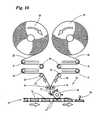
- the preferred field of application for the innovationsare methods and apparatus for producing foil pouches, in particular in the form of tobacco pouches 10 for receiving a portion of tobacco.
- Thisconsists of a pocket 11, which is formed by folding a corresponding (rectangular) foil blank, with bag front wall 12 and bag rear wall 13.
- the bag walls 12, 13are connected to each other by side seams 14 due to thermal sealing.
- a removal opening 15 between the bag walls 12, 13is closed by transverse sealing seam - after filling the bag 11.
- the closure seam 16is designed such that it can be easily opened when the package is put into use.
- the tobacco bag 10has a tab 17 which is formed as an extension of the bag rear wall 13 and thus as part of the one-piece foil blank.
- the tab 17may be sized so that it is folded as a closure tab against the bag front wall 12 and connected thereto.
- the lug 17is designed as a winding lug which, in the closed position, encloses the bag front wall 12 and is detachably fixed to the bag rear wall 13 by means of an edge-side connecting means ( Fig. 3 ).
- connecting piecesare provided, which are on the one hand on the (inside of) the tab 17 and on the other hand attached to the bag wall 12 or 13.
- the connecting piecesare designed so that they enter into a releasable connection due to pressing against each other.
- the connecting piecesare formed as Velcro pieces 18, 19.
- the Velcro pieces 18, 19, preferably in a matching embodiment,have on the mutually facing sides of a strip-shaped carrier 21 each have a hook and loop coating 20.
- a permanently acting adhesive 22is arranged. By this adhesive 22, the Velcro pieces 18, 19 are attached to the tobacco bag 10 in the manner described.
- a special featureis that the Velcro pieces 18, 19 of the pack or the tobacco bag 10 are supplied as a prefabricated unit 23. Two Velcro pieces 18, 19 are joined together in the area of the Velcro coating 20 to form the unit 23. The free sides of the unit 23 and the Velcro pieces 18, 19 are preferably provided with the adhesive 22. This can alternatively be applied to the package or to the tobacco bag 10 in the region of the hook and loop pieces 18, 19 to be attached.
- Each tobacco pouch 10is provided with at least one unit 23. This can be attached in a first step on the inside of the tab 17 packaged, namely by means of adhesive 22 of a hook and loop fastener 18 are attached. Thereafter, the tab 17 is brought into the closed position ( Fig. 3 ), whereby the free side of the unit 23 and the other Klett Cultures 19 receives investment on the bag front wall 12 or - preferably - on the bag rear wall 13. Again, the unit 23 is fixed by means of adhesive 22. Now, the tobacco bag 10 and the tab 17 can be opened and closed several times in the usual way, each with separation and rejoining the Velcro pieces 18, 19th
- the unit 23may be attached to the bag wall, preferably the bag back wall 13, in a first step, preferably after filling and Closing the bag 11.
- the unit 23is connected to the tab 17 also in this procedure.
- a respective hook and loop piece 18is connected to the tab 17 and a hook and loop piece 19 to the bag rear wall 13.
- the units 23can be manufactured in the region of a packaging machine and fed to the tobacco bags 10 in a transfer station 24. Alternatively, otherwise manufactured units 23 may be conveniently transferred to the transfer station 24.
- the double strip 27can be created in different ways.
- Fig. 4such as 10 to FIG. 13 two separate Velcro strips 25, 26 are brought together, such that the Velcro coatings 20 are facing each other.
- Velcro strips 25, 26are connected together to form a continuous double strip 27th
- the two Velcro tapes 25, 26 to be unitedare stored (above the transfer station 24) as adjacent strip robots 28, 29. Of these, the bands 25, 26 are withdrawn and fed to the transfer station 24 via first stationary deflection rollers 30 in horizontal loops. Above and below movable dancer rollers 31, 32 are arranged, which perform (in the horizontal plane) a compensating movement and a constant tension in the Velcro strips 25, 26 obtained. Lower stationary (second) guide rollers 33 guide the hook and loop fasteners 25, 26 in a converging downward direction to a connecting member. This has pressure rollers 34, 35 on both sides of the Velcro strips 25, 26. The rollers are driven according to the direction of movement of the Velcro strips 25, 26 (arrows). Of the Distance of the lateral surfaces is chosen so that the Velcro strips 25, 26 are brought together in the area of the Velcro coatings 20 and interconnected.
- the lateral surfaces of the pressure rollers 34, 35are formed in a special way, according to the embodiment Fig. 13 with convergent projections, which are tooth-shaped in the present case. The tips of these projections receive contact with the adhesive side of the Velcro strips 25, 26. Additionally or alternatively, the lateral surface of the pressure rollers 34, 35 or the projections may be provided with a silicone coating to adhere the Velcro strips 25, 26 to the pressure rollers 34, 35 to avoid.
- a separating memberfor the production of the units 23.
- Thisconsists of separating knives, in this case from a stationary cutting blade 36 with trapezoidal cross-section.
- a counter knife 37 arranged below the separating knife 36is movable transversely to the plane of the double strip 27 and, in cooperation with the separating knife 36, separates a unit 23 from the double strip 27 at each working cycle. This is transmitted by the counter knife 37 to a holder 38.
- the counter knife 37forms by trapezoidal cross-sectional shape an (upper) cutting edge 39.
- a compensating piecepreferably made of silicone, on which the separated unit 23 rests in the separation process.
- suction holes 40are arranged, which open at a (vertical) contact surface of the counter blade 37 and are connected to a suction channel 41 in the counter blade 37.
- the unit 23abuts against the (coated with silicone) contact surface of the counter blade 37 and is held (in addition) by suction.
- the unit 23In the end position of the transverse movement of the counter blade 37, the unit 23 receives contact with a holder 38, which takes over the unit 23.
- the holder 38is provided with a pad 42 of silicone or other suitable material.
- the unit 23is held on the pad 42, in particular by suction, which is generated via suction holes 43.
- suctionWhen transferring the unit 23 from one carrier to the other, the suction air is blocked in the area of the counter blade 37, optionally reversed in compressed air. At the same time, the suction air on the suction holes 43 on the holder 38 is effective.
- the double strip 27is assigned a support element arranged above the knives 36, 37.
- Thisconsists of a rotationally driven support roller 68, which is arranged on the opposite side of the counter-blade 36 of the double strip 27.
- the support roller 85is provided with measures that prevent sticking of the double strip 27, in particular with tooth-like projections and / or silicone coating.
- the holder 38is used for further transport of the unit 23.
- the holder 38serves for (direct) transmission of the unit 23 to a tobacco pouch 10.
- a plurality of, in the present case four holders 38are arranged on a movable carrier, in particular on a cyclically rotating transfer roller 44, as a radially projecting, with the same Spaced apart stamps, at the outer end of the unit 23 is held.
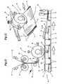
- the relative position of the above a trajectory for the tobacco bag 10, in particular above a bag path 45 arranged transfer member 44is selected so that during a standstill phase, a unit 23 in the region of the separation station 37, 38 taken over and at the same time - by a downwardly directed holder 38 - a Unit 23 is transferred to a tobacco bag 10.
- the tobacco pouches 10are cyclically transported by a (horizontal) bag conveyor 45, the bag 11 filled with tobacco and closed in the region of the removal opening 15 lying on a belt 46 with drivers 47 on both sides (front and rear) of the tobacco pouch 10.
- Each tobacco pouch 10is suitably positioned and aligned between the dogs 47.
- the (winding) tab 17is already partially wrapped after closing the bag 11, so that the bag front wall 12 is directed with the voltage applied to this part of the tab 17 down and rests on the belt 46.
- the bag rear wall 13 facing part of the tab 17is directed upwards as a free leg and receives investment - approximately in the vertical plane - on a stationary guide, here on a guide rail 48, against which the tab 17 and the free leg slidably.
- the units 23are placed on the upwardly directed bag rear wall 13.
- the suction air in the region of the holder 38is controlled away, optionally, compressed air is transmitted, so that the unit 23 reliably on the Tobacco bag 10 is transferred.
- the tab 17is folded into the closed position or until it rests against the bag rear wall 13. At the same time the tab 17 is connected to the free, coated with adhesive 22 side of the unit 23.
- a ram 84 arranged above the pouch web 45acts, which exerts pressure in the area of the velcro pieces 18, 19 on the outside of the pouch 10 or the flap 17 to stabilize the connection.
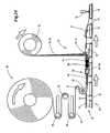
- the (Velcro) unit 23is made of a special strip of material 49, which is supplied as an industrial precursor of the packaging machine.
- the material strip 49consists of a strip-shaped carrier tape 50, in particular made of plastic.
- Each Velcro strip 51, 52consists of erected Velcro structures, in particular of hook-shaped projections 53 (in detail in FIG Fig. 16 ). These can be applied to the carrier tape 50 or be formed by appropriate shaping of the material of the carrier tape.
- the mutually parallel Velcro strips 51, 52are positioned at a distance from each other on the carrier tape 50. Between the adjacent Velcro strips 51, 52 a folding edge 54 is formed. This can be defined by a weakening line, in particular by a perforation line, preferably centrally between the Velcro strips 51, 52. Adjacent to the Velcro strips 51, 52, ie on the free side of the carrier tape 50, an adhesive is attached, here a continuous layer of adhesive 22. Furthermore, a cover of the free side of the adhesive 22 is provided in the present case, namely a cover strip of thin film , This is removed before separating the units 23. In the illustrated embodiment, a material strip 49 two cover strips 55, 56 assigned. These are shared or divisible. In the example of Fig.
- the cover strips 55, 56 associated with each Velcro strip 51, 52are centered, namely in the region of the folded edge 54, separated from one another by a continuous gap 57 or are easily separable by a correspondingly attached perforation.
- the material strip 49is deformed, namely folded in the longitudinal direction between the Velcro strips 51, 52, as a result, a double strip 27 is formed in which the adjacent Velcro strips 51, 52 due to the Velcro connection to each other ( Fig. 18 ).
- a double strip 27is formed in which the adjacent Velcro strips 51, 52 due to the Velcro connection to each other ( Fig. 18 ).
- the cover strips 55, 56are thereby separated, but initially still remain in the covering position. From the resulting double strip 27, the units 23 can be separated, in particular after prior removal of the cover strip 55, 56th
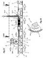
- a belt bobbin 58is positioned as a supply for the material strip 49 in the region of the transfer station 24 above a movement path of the tobacco bag 10, in particular above the bag conveyor 45 in the embodiment described.
- the material strip 49is preferably clocked withdrawn from the belt bobbin 58 and fed via movably mounted deflection rollers 59 a manufacturing section 62 for producing the units 23.
- the (unfolded) strip of material 49is guided above the movement path of the tobacco bag 10 via a further deflection roller, which is also the drive or preferred roller 60 for the material strip 49. With the help of a guide roller, namely roughing roller 61, a wrap angle of at least 180 ° is created. Subsequent to the preferred roller 60, the material strip 49 is transported into the (horizontal) production section 62.
- the preferred roller 60is designed in a special way ( Fig. 16 ), namely provided with particular sawtooth-like drivers 63 on the circumference. These are matched to the structure of the Velcro strips 51, 52 in terms of training, arrangement and dimension. Conveniently, the projections 53 and hook-shaped connecting members are arranged in ordered formation, in particular in transverse rows. The dogs 63 of the preferred roller 60 enter into areas between adjacent projections 53 and transverse rows of the same, in order to promote the material strip 49 or Velcro strips 25, 26 without slipping.
- the feed roller 60is driven cyclically, namely according to the production of a unit 23 by separating from the web 49.
- the roughing roller 61is synchronously with the (cyclic) conveying movement of the web 49 in the circumferential direction of the preferred roller 60 back and forth to compensate for movement without effect to effect on the balancing or deflection rollers 59.
- a folding station adjoining the preferred roller 60 in the conveying directionis formed.
- the V-shaped folding of the material strip 49takes place in the region between the preferred roller 60 and members for compressing the legs of the folded strip of material 49 (FIGS. Fig. 18 ).
- rotatable pressure rollers 64, 65 about upright axesare arranged on both sides of the movement path of the material strip 49.
- the spread in a horizontal plane (running from the feed roller 60) strip of material 49is folded on the way to the pressure rollers 64, 65, so that the legs formed, each with a Velcro strips 51, 52 in the region of the pressure rollers 64, 65 to each other ( Fig. 18 ).
- the pressure rollers 64, 65have (mutually) edge-side guide discs 66, 67, which cause a guide of the (folded) material strip 46 in the vertical direction.
- the prepared, namely folded strip of material 49is fed in a preferably vertical orientation of a separation station for separating the units 23 successively at the front end of the formed from the strip of material 49 double stripe 27.
- a separation stationfor separating the units 23 successively at the front end of the formed from the strip of material 49 double stripe 27.
- are in an area between the Pressure rollers 64, 65 and a separating memberfurther preferred rollers 68, 69 arranged in pairs on both sides of the double strip 27.
- the preferred rollers 68, 69are preferably provided with a peripheral coating made of plastic, rubber or other material with a high coefficient of friction and preferably geared so with the preferred roller 60 that a coordinated transport of the material strip 49 and the double strip 27 takes place.
- the cover strips 55, 56are eliminated.
- the cover strips 55, 56 exposed on both sides of the double strip 27are pulled off the respective layer of the adhesive 22 and led out of the region of the double strip 27 by deflection.
- the peeled cover strips 55, 56are moved upwards and wound onto a collecting rack 72.
- a separatorThis consists in the present example of a combined separating and pressing member, in particular a cutting punch 73.
- a cutting punch 73This is above the trajectory of the tobacco pouch 10 fixedly positioned and transversely movable, in height or in the plane of the transport path also above the bag 10 Double strip 27.
- the cutting punch 73is transversely movable in a cutting station (arrow).
- a front end of the cutting punch 73is provided with a separating knife 74 or designed as a separating knife (with trapezoidal cross-section). In a starting position, separating blades 74 and counter blades 75 are located on opposite sides of the double strip 27.
- a unit 23is separated from the double strip 27 the cutting punch 73 detected and with continued movement of the cutting punch 73 until it rests against the bag 10, in this case at the upright positioned tab 17.
- the unit 23is pressed by the cutting punch 73 against the inside of the tab 17.
- a counter-pressure member 76plate is positioned on the opposite side of the tab 17 so that sufficient pressure for fixing the unit 23 can be transferred. The cutting punch 23 then returns to the starting position.
- transverse guide members or cylindrical guide rods 79are arranged above and below the movement path of the double strip 27, in the conveying direction in front of the cutting punch 73 or in front of the deflecting rods 70, 71. As a result, the double strip 27 is aligned in height exactly.
- the tobacco bag 10is folded after attaching the unit 23 with continued transport.
- the tab 17is folded against the pocket 11 and against the bag rear wall 13 in the horizontal position.
- a Guide rail 77effective, which runs above the path of movement of the tobacco bag 10 at the level of the tab 17 and due to arcuate design, the process of folding the flap 17 causes to rest on the bag 11.
- the connection with the (filled) pocket 11stabilized by a pressure acting from above pressure element, in this case by a closing punch 78.
- Thisis effective with an extendable plunger in the region of the unit 23 to secure the (two-sided) connection with the tobacco bag 10. This can then be transported away for the packaging.
Landscapes
- Engineering & Computer Science (AREA)
- Mechanical Engineering (AREA)
- Manufacture Of Tobacco Products (AREA)
- Packaging Of Annular Or Rod-Shaped Articles, Wearing Apparel, Cassettes, Or The Like (AREA)
- Wrapping Of Specific Fragile Articles (AREA)
Description
Translated fromGermanDie Erfindung betrifft ein Verfahren zum Herstellen von (Tabak-)Beutelpackungen mit Klettstücken zum Fixieren einer Lasche in Schließstellung und den übrigen Merkmalen im Oberbegriff des Anspruchs 1. Weiterhin betrifft die Erfindung eine Vorrichtung zum Durchführen des Verfahrens.The invention relates to a method for producing (tobacco) bag packages with Velcro pieces for fixing a tab in the closed position and the other features in the preamble of
Bekannt sind Beutelpackungen aus Folie mit einer Lasche, insbesondere Tabakbeutel mit einer als Fortsetzung einer Beutelrückwand ausgebildeten Verschlusslasche bzw. Wickellasche und mit Klettstücken zum Fixieren der Lasche in Schließstellung an einer Beutel-Vorderwand oder an einer Beutel-Rückwand (
Bekannt ist die Anbringung von durchgehenden Klettstreifen in der Öffnung eines Beutels als mehrfach benutzbares Verschlussmittel der Beutelöffnung (
Bei (Tabak-)Beuteln mit Verschluss- oder Wickellasche werden bisher überwiegend klebende Streifen (Tapes) zum Fixieren der Lasche in Schließstellung eingesetzt (
Der Erfindung liegt die Aufgabe zugrunde, die vorstehenden Probleme bei der Herstellung von Packungen mit Klettstücken zur Fixierung einer Lasche zu vermeiden und insbesondere die Anbringung der Klettstücke in einer exakten Relativstellung zu verbessern.The invention has for its object to avoid the above problems in the production of packages with Velcro pieces for fixing a tab and in particular to improve the attachment of the Velcro pieces in an exact relative position.
Zur Lösung dieser Aufgabe ist das erfindungsgemäße Verfahren durch die Merkmale des Anspruchs 1 gekennzeichnet.To solve this problem, the inventive method is characterized by the features of
Die insbesondere rechteckigen oder quadratischen Klettstücke werden demnach zuerst mit ihrer haftenden Beschichtung, insbesondere mit ihrer Klettbeschichtung verbunden zu einer Einheit aus zwei Stücken. Diese Einheit wird dann entweder auf die (Verschluss-)Lasche oder auf die Packungs- bzw. Beutelwand aufgebracht und mit dieser durch Klebung oder in anderer Weise verbunden. Dieser Verfahrensschritt wird bei geöffneter Packung bzw. geöffnetem Beutel vollzogen. Danach wird die Lasche in die Verschlussstellung gebracht, wobei je nach Position der Einheit aus den Verbindungsstücken die freie Seite eines der Verbindungsstücke der Einheit entweder mit der Lasche oder mit einer Packungs- bzw. Beutelwand verbunden wird.The particular rectangular or square Velcro pieces are therefore first connected with their adhesive coating, in particular with their Velcro coating into a unit of two pieces. This unit is then either applied to the (closure) tab or to the packing or bag wall and bonded thereto by gluing or otherwise. This process step is performed with the package open or the bag open. Thereafter, the tab is brought into the closed position, wherein, depending on the position of the unit from the connecting pieces, the free side of one of the connecting pieces of the unit is connected either to the tab or to a packing or bag wall.
Die Klettstücke werden vorzugsweise von einem Materialstreifen abgetrennt, wobei erfindungsgemäß zwei fortlaufende Klettstreifen im Bereich der Klettbeschichtung aneinander liegen und durch Aneinanderdrücken verbunden sind. Von diesem Doppelstreifen werden dann entsprechende Einheiten aus (zwei) Klettstücken abgetrennt und einer Packung zugeführt.The Velcro pieces are preferably separated from a strip of material, wherein according to the invention two continuous Velcro strips in the region of the Velcro coating are adjacent to each other and are connected by pressing against each other. From this double strip then appropriate units of (two) Klett pieces are separated and fed to a pack.
Die Doppelstreifen aus zwei Klettstreifen können aus einzelnen, fortlaufenden Klettbändern durch Zusammenführen und Aneinanderdrücken unmittelbar im Bereich der Verarbeitung hergestellt werden. Besonders vorteilhaft ist jedoch die Verwendung eines Materialstreifens mit mindestens zwei nebeneinander angeordneten und parallel verlaufenden Klettstreifen. Diese Ausgangsbahn wird entlang einer Linie zwischen benachbarten Klettstreifen gefaltet, derart, dass die beiden Klettstreifen einander zugekehrt und durch Zusammendrücken miteinander verbunden werden können. Von dem so ausgebildeten Doppelstreifen werden die Einheiten abgetrennt und der Packung bzw. dem Beutel zugeführt. Die Materialbahn bzw. ein Trägerband für die (zwei) Klettstreifen ist vorzugsweise mit einer Schwächungslinie versehen, so dass der Materialstreifen während des Zusammenfügens der Klettstreifen durchtrennt werden kann. Vorteilhaft ist eine Durchtrennung der Einheit nach Anbringen an der Packung bzw. am Beutel, wobei die Relativstellung so gewählt ist, dass beim Öffnungsvorgang und damit verbundenem Trennen der Klettstücke der Träger durchtrennt wird.The double strips of two Velcro strips can be made from single, continuous Velcro strips by merging and pressing together directly in the processing area. However, it is particularly advantageous to use a strip of material with at least two juxtaposed and parallel Velcro strips. This starting web is folded along a line between adjacent Velcro strips, such that the two Velcro strips can face each other and be joined together by compression. From the double strip thus formed, the units are separated and fed to the package or the bag. The material web or a carrier tape for the (two) Velcro strips is preferably provided with a weakening line, so that the material strip can be severed during the assembly of the Velcro strips. Advantageously, a separation of the unit after attachment to the package or the bag, wherein the relative position is selected so that the carrier is severed during the opening process and associated separation of the Velcro pieces.
Weiterhin bezieht sich die Erfindung auf Vorrichtungen zum Herstellen der Verbindungs- bzw. Kletteinheiten und zur Übertragung derselben auf (Tabak-)Beutel.Furthermore, the invention relates to devices for producing the Klätinheiten and for transmitting the same on (tobacco) bag.
Einzelheiten des erfindungsgemäßen Verfahrens und der Vorrichtung werden nachfolgend anhand von in den Zeichnungen dargestellten Ausführungsbeispielen erläutert. Es zeigt:
- Fig. 1
- eine Beutelpackung für Tabak in perspektivischer Öffnungsstellung,
- Fig. 2
- die Beutelpackung gemäß
Fig. 1 in Ansicht von der Rückseite, - Fig. 3
- die Beutelpackung gemäß
Fig. 1, Fig. 2 in Schließstellung, ebenfalls perspektivisch, - Fig. 4
- eine Einzelheit, nämlich eine Klettverbindung von Lasche und Beutelwandung im Querschnitt, in vergrößertem Maßstab,
- Fig. 5
- eine Darstellung entsprechend
Fig. 4 eines anderen Ausführungsbeispiels einer Klettverbindung, - Fig. 6
- einen Abschnitt einer Materialbahn zum Herstellen von doppelten Klettstreifen in perspektivischer Darstellung,
- Fig. 7
- die Materialbahn gemäß
Fig. 6 im Querschnitt, - Fig. 8
- eine Darstellung analog
Fig. 7 eines anderen Ausführungsbeispiels, - Fig. 9
- eine Zwischenstellung bei der Fertigung eines doppelten Klettstreifens aus einer Materialbahn gemäß
Fig. 6 , - Fig. 10
- einen Ausschnitt einer Vorrichtung zum Herstellen bzw. Fertigstellen von Beutelpackungen in schematischer Seitenansicht,
- Fig. 11
- eine Einzelheit der Vorrichtung gemäß
Fig. 10 in vergrößertem Maßstab, - Fig. 12
- eine Station zum Aufbringen von Kletteinheiten auf eine Beutelpackung in vergrößertem Maßstab bei perspektivischer Darstellung,
- Fig. 13
- ein Detail der Vorrichtung gemäß
Fig. 11 in nochmals vergrößertem Maßstab, teilweise im Vertikalschnitt, - Fig. 14
- eine andere Ausführungsform einer Vorrichtung zum Herstellen von (Klett-)Einheiten und Anbringung an einer Packung in schematischer Seitenansicht,
- Fig. 15
- einen Ausschnitt der Vorrichtung gemäß
Fig. 14 in vergrößertem Maßstab, - Fig. 16
- einen Ausschnitt eines Förderorgans für eine Materialbahn, in vergrößertem Maßstab,
- Fig. 17
- die Einzelheit gemäß
Fig. 15 in Draufsicht entsprechend Sichtebene XVII-XVII derFig. 15 , - Fig. 18
- Andrückwalzen für die gefaltete Materialbahn im Querschnitt entsprechend Schnittebene XVIII-XVIII in
Fig. 17 , - Fig. 19
- ein Organ zum Anbringen von (Klett-)Einheiten an einem Beutel in der Schnitt-bzw. Sichtebene XIX-XIX der
Fig. 17 .
- Fig. 1
- a bag package for tobacco in a perspective opening position,
- Fig. 2
- the bag pack according to
Fig. 1 in view from the back, - Fig. 3
- the bag pack according to
Fig. 1, Fig. 2 in closed position, also in perspective, - Fig. 4
- a detail, namely a Velcro connection of flap and bag wall in cross-section, on an enlarged scale,
- Fig. 5
- a representation accordingly
Fig. 4 another embodiment of a Velcro connection, - Fig. 6
- a section of a material web for producing double Velcro strips in perspective,
- Fig. 7
- the material web according to
Fig. 6 in cross section, - Fig. 8
- a representation analog
Fig. 7 another embodiment, - Fig. 9
- an intermediate position in the production of a double Velcro strip of a material web according to
Fig. 6 . - Fig. 10
- a detail of a device for producing or finishing of bag packages in a schematic side view,
- Fig. 11
- a detail of the device according to
Fig. 10 on an enlarged scale, - Fig. 12
- a station for applying burdock units to a bag package on an enlarged scale in a perspective view,
- Fig. 13
- a detail of the device according to
Fig. 11 on a further enlarged scale, partly in vertical section, - Fig. 14
- another embodiment of a device for producing (Velcro) units and attachment to a pack in a schematic side view,
- Fig. 15
- a section of the device according to
Fig. 14 on an enlarged scale, - Fig. 16
- a section of a conveying member for a material web, on an enlarged scale,
- Fig. 17
- the detail according to
Fig. 15 in plan view according to viewing plane XVII-XVII ofFig. 15 . - Fig. 18
- Pressure rollers for the folded material web in cross section corresponding to sectional plane XVIII-XVIII in
Fig. 17 . - Fig. 19
- an organ for attaching (Velcro) units to a bag in the cut resp. Viewing plane XIX-XIX the
Fig. 17 ,
Das bevorzugte Anwendungsgebiet für die Neuerungen sind Verfahren und Vorrichtung zum Herstellen von Beutelpackungen aus Folie, insbesondere in der Ausführung als Tabakbeutel 10 für die Aufnahme einer Tabakportion. Dieser besteht aus einer Tasche 11, die durch Falten eines entsprechenden (rechteckigen) Folienzuschnitts gebildet wird, und zwar mit Beutel-Vorderwand 12 und Beutel-Rückwand 13. Die Beutelwände 12, 13 sind durch Seitennähte 14 aufgrund thermischer Siegelung miteinander verbunden. Eine Entnahmeöffnung 15 zwischen den Beutelwänden 12, 13 ist durch quergerichtete Verschlussnaht - nach dem Füllen der Tasche 11 - verschlossen. Die Verschlussnaht 16 ist so ausgebildet, dass sie bei Ingebrauchnahme der Packung leicht geöffnet werden kann.The preferred field of application for the innovations are methods and apparatus for producing foil pouches, in particular in the form of
Der Tabakbeutel 10 weist eine Lasche 17 auf, die als Verlängerung der Beutel-Rückwand 13 und damit als Teil des einstückigen Folienzuschnitts gebildet ist. Die Lasche 17 kann so bemessen sein, dass sie als Verschlusslasche gegen die Beutel-Vorderwand 12 gefaltet und mit dieser verbunden wird. Alternativ - nämlich gemäß vorliegendem Ausführungsbeispiel - ist die Lasche 17 als Wickellasche ausgebildet, die in Schließstellung die Beutel-Vorderwand 12 umschließt und mit einem randseitigen Verbindungsmittel an der Beutel-Rückwand 13 lösbar fixiert ist (
Zur (lösbaren) Verbindung der Lasche 17 mit der einen oder anderen Beutelwand 12, 13 sind Verbindungsstücke vorgesehen, die einerseits an der (Innenseite der) Lasche 17 und andererseits an der Beutelwand 12 oder 13 angebracht sind. Die Verbindungsstücke sind so ausgebildet, dass sie aufgrund von Aneinanderdrücken eine lösbare Verbindung eingehen. Vorzugsweise sind die Verbindungsstücke als Klettstücke 18, 19 ausgebildet. Die Klettstücke 18, 19, vorzugsweise in übereinstimmender Ausführung, weisen an den einander zugekehrten Seiten eines streifenförmigen Trägers 21 jeweils eine Klettbeschichtung 20 auf. Gegenüberliegend, nämlich auf der der Lasche 17 bzw. der Beutelwandung 12, 13 zugekehrten Seite ist ein dauerhaft wirkender Kleber 22 angeordnet. Durch diesen Kleber 22 sind die Klettstücke 18, 19 in der beschriebenen Weise an dem Tabakbeutel 10 befestigt.For (releasable) connection of the
Eine Besonderheit besteht darin, dass die Klettstücke 18, 19 der Packung bzw. dem Tabakbeutel 10 als vorgefertigte Einheit 23 zugeführt werden. Zwei Klettstücke 18, 19 sind im Bereich der Klettbeschichtung 20 miteinander verbunden unter Bildung der Einheit 23. Die freien Seiten der Einheit 23 bzw. der Klettstücke 18, 19 sind vorzugsweise mit dem Kleber 22 versehen. Dieser kann alternativ auf die Packung bzw. auf den Tabakbeutel 10 im Bereich der anzubringenden Klettstücke 18, 19 aufgetragen werden.A special feature is that the
Jeder Tabakbeutel 10 wird mit mindestens einer Einheit 23 versehen. Diese kann in einem ersten Schritt an der Innenseite der Lasche 17 packungsgerecht angebracht, nämlich mittels Kleber 22 des einen Klettstücks 18 befestigt werden. Danach wird die Lasche 17 in die Schließstellung gebracht (
Alternativ kann die Einheit 23 in einem ersten Schritt an der Beutelwand, vorzugsweise der Beutel-Rückwand 13 angebracht werden, und zwar vorzugsweise nach dem Füllen und Verschließen der Tasche 11. Durch Schließen der Lasche 17 wird auch bei diesem Vorgehen die Einheit 23 mit der Lasche 17 verbunden. Im Ergebnis ist je ein Klettstück 18 mit der Lasche 17 und ein Klettstück 19 mit der Beutel-Rückwand 13 verbunden.Alternatively, the
Die Einheiten 23 können im Bereich einer Verpackungsmaschine hergestellt und den Tabakbeuteln 10 in einer Übertragungsstation 24 zugeführt werden. Alternativ können anderweitig gefertigte Einheiten 23 in geeigneter Weise der Übertragungsstation 24 übergeben werden.The
Zur Herstellung der aus zwei Klettstücken 18, 19 bestehenden Einheiten 23 gemäß
Der Doppelstreifen 27 kann auf unterschiedliche Weise geschaffen werden. Bei dem Ausführungsbeispiel gemäß
Die beiden zu vereinigenden Klettbänder 25, 26 sind (oberhalb der Übertragungsstation 24) als nebeneinanderliegende Streifenbobinen 28, 29 gespeichert. Von diesen werden die Bänder 25, 26 abgezogen und der Übertragungsstation 24 über erste ortsfeste Umlenkrollen 30 in horizontalen Schleifen zugeführt. Oberhalb und unterhalb sind bewegbare Tänzerrollen 31, 32 angeordnet, die (in horizontaler Ebene) eine Ausgleichsbewegung ausführen und eine konstante Spannung in den Klettbändern 25, 26 erhalten. Untere, ortsfeste (zweite) Umlenkrollen 33 führen die Klettbänder 25, 26 in konvergierender Abwärtsrichtung einem Vereinigungsorgan zu. Dieses weist Andrückrollen 34, 35 zu beiden Seiten der Klettbänder 25, 26 auf. Die Rollen werden entsprechend der Bewegungsrichtung der Klettbänder 25, 26 angetrieben (Pfeile). Der Abstand der Mantelflächen ist so gewählt, dass die Klettbänder 25, 26 im Bereich der Klettbeschichtungen 20 zusammengeführt und miteinander verbunden werden.The two
Da die Klettbänder 25, 26 an den den Andrückrollen 34, 35 zugekehrten Außenseiten eine Beschichtung mit Kleber 22 aufweisen, sind die Mantelflächen der Andrückrollen 34, 35 in besonderer Weise ausgebildet, bei dem Ausführungsbeispiel gemäß
Unterhalb der Andrückrollen 34, 35, oberhalb der zu beschickenden Tabakbeutel 10, befindet sich ein Trennorgan für die Herstellung der Einheiten 23. Dieses besteht aus Trennmessern, vorliegend aus einem ortsfesten Trennmesser 36 mit trapezförmigem Querschnitt. Ein unterhalb des Trennmessers 36 angeordnetes Gegenmesser 37 ist quer zur Ebene des Doppelstreifens 27 bewegbar und trennt dabei im Zusammenwirken mit dem Trennmesser 36 bei jedem Arbeitstakt eine Einheit 23 von dem Doppelstreifen 27 ab. Dieser wird durch das Gegenmesser 37 an einen Halter 38 übertragen. Das Gegenmesser 37 bildet durch trapezförmige Querschnittsform eine (obere) Schneidkante 39. Darunter befindet sich ein Ausgleichsstück, vorzugsweise aus Silikon, an dem die abgetrennte Einheit 23 bei dem Trennvorgang anliegt. In diesem Bereich sind darüber hinaus Saugbohrungen 40 angeordnet, die an einer (vertikalen) Anlagefläche des Gegenmessers 37 münden und an einen Saugkanal 41 im Gegenmesser 37 angeschlossen sind. Die Einheit 23 liegt an der (mit Silikon beschichteten) Anlagefläche des Gegenmessers 37 an und wird (zusätzlich) durch Saugluft gehalten.Below the
In der Endstellung der Querbewegung des Gegenmessers 37 erhält die Einheit 23 Anlage an einem Halter 38, der die Einheit 23 übernimmt. Der Halter 38 ist mit einem Anlagestück 42 aus Silikon oder anderem geeigneten Werkstoff versehen. Die Einheit 23 wird an dem Anlagestück 42 gehalten, insbesondere durch Saugluft, die über Saugbohrungen 43 erzeugt wird. Bei der Übergabe der Einheit 23 von dem einen Träger zum anderen wird die Saugluft im Bereich des Gegenmessers 37 gesperrt, gegebenenfalls in Druckluft umgesteuert. Zugleich wird die Saugluft über die Saugbohrungen 43 an dem Halter 38 wirksam.In the end position of the transverse movement of the
Im Bereich der Trennstation, also der Messer 36, 37, ist dem Doppelstreifen 27 ein oberhalb der Messer 36, 37 angeordnetes Stützorgan zugeordnet. Dieses besteht aus einer drehend angetriebenen Stützrolle 68, die an der zum Gegenmesser 36 gegenüberliegenden Seite des Doppelstreifens 27 angeordnet ist. Die Stützrolle 85 ist mit Maßnahmen versehen, die ein Kleben des Doppelstreifens 27 verhindern, insbesondere mit zahnartigen Vorsprüngen und/oder Silikonbeschichtung.In the area of the separation station, that is to say the
Der Halter 38 dient zum Weitertransport der Einheit 23. Bei dem vorliegenden Ausführungsbeispiel (
Die Tabakbeutel 10 werden durch einen (horizontalen) Beutelförderer 45 taktweise transportiert, wobei die mit Tabak gefüllte, im Bereich der Entnahmeöffnung 15 geschlossene Tasche 11 auf einem Gurt 46 mit Mitnehmern 47 zu beiden Seiten (vorn und hinten) der Tabakbeutel 10 liegt. Jeder Tabakbeutel 10 ist passend zwischen den Mitnehmern 47 positioniert und ausgerichtet. Bei diesem Vorgehen ist die (Wickel-)Lasche 17 nach dem Schließen der Tasche 11 bereits teilweise gewickelt, sodass die Beutel-Vorderwand 12 mit dem an dieser anliegenden Teil der Lasche 17 nach unten gerichtet ist und auf dem Gurt 46 aufliegt. Der der Beutel-Rückwand 13 zugekehrte Teil der Lasche 17 ist als freier Schenkel aufwärts gerichtet und erhält Anlage - etwa in vertikaler Ebene - an einer ortsfesten Führung, hier an einer Leitschiene 48, an der die Lasche 17 bzw. der freie Schenkel gleitend anliegt.The
Die Einheiten 23 werden auf die nach oben gerichtete Beutel-Rückwand 13 aufgelegt. Bei der Übergabe einer Einheit 23 wird die Saugluft im Bereich des Halters 38 weggesteuert, gegebenenfalls wird Druckluft übertragen, sodass die Einheit 23 zuverlässig auf den Tabakbeutel 10 übertragen wird. Anschließend wird durch entsprechende Form der Leitschiene 48 bei Weitertransport der Tabakbeutel 10 die Lasche 17 in die Schließstellung bzw. bis zur Anlage an der Beutel-Rückwand 13 umgefaltet. Zugleich wird die Lasche 17 mit der freien, mit Kleber 22 beschichteten Seite der Einheit 23 verbunden. Um die Verbindung der Einheit 23 mit dem Tabakbeutel 10 zu sichern, wird bei Weitertransport der Tabakbeutel 10 ein oberhalb der Beutelbahn 45 angeordneter Stößel 84 wirksam, der im Bereich der Klettstücke 18, 19 an der Außenseite des Beutels 10 bzw. der Lasche 17 Druck ausübt, um die Verbindung zu stabilisieren.The
Technisch und wirtschaftlich besonders vorteilhaft ist die Alternative, die sich aus
Die (Klett-)Einheit 23 wird aus einem besonderen Materialstreifen 49 gefertigt, der als industrielles Vorprodukt der Verpackungsmaschine zugeführt wird. Der Materialstreifen 49 besteht aus einem streifenförmigen Trägerband 50, insbesondere aus Kunststoff. Auf diesem, nämlich auf einer Seite des Trägerbands, sind mehrere, insbesondere zwei parallele Klettstreifen 51, 52 angebracht. Jeder Klettstreifen 51, 52 besteht aus aufgerichteten Klettstrukturen, insbesondere aus hakenförmigen Vorsprüngen 53 (im Einzelnen in
Die parallel zueinander verlaufenden Klettstreifen 51, 52 sind mit Abstand voneinander auf dem Trägerband 50 positioniert. Zwischen den benachbarten Klettstreifen 51, 52 ist eine Faltkante 54 gebildet. Diese kann durch eine Schwächungslinie, insbesondere durch eine Perforationslinie vorzugsweise mittig zwischen den Klettstreifen 51, 52 definiert sein. Gegenüberliegend zu den Klettstreifen 51, 52, also an der freien Seite des Trägerbands 50, ist ein Haftmittel angebracht, hier eine durchgehend Schicht eines Klebers 22. Des Weiteren ist vorliegend eine Abdeckung der freien Seite des Klebers 22 vorgesehen, nämlich ein Abdeckstreifen aus dünner Folie. Diese wird vor dem Abtrennen der Einheiten 23 entfernt. Bei dem dargestellten Ausführungsbeispiel sind einem Materialstreifen 49 zwei Abdeckstreifen 55, 56 zugeordnet. Diese sind voneinander geteilt bzw. teilbar. Bei dem Beispiel der
Der Materialstreifen 49 wird so verformt, nämlich in Längsrichtung zwischen den Klettstreifen 51, 52 gefaltet, dass im Ergebnis ein Doppelstreifen 27 entsteht, bei dem die benachbarten Klettstreifen 51, 52 aufgrund der Klettverbindung aneinander liegen (
Zweckmäßigerweise wird eine Bandbobine 58 als Vorrat für den Materialstreifen 49 im Bereich der Übertragungsstation 24 oberhalb einer Bewegungsbahn der Tabakbeutel 10 positioniert, insbesondere oberhalb des Beutelförderers 45 in der beschriebenen Ausführung. Der Materialstreifen 49 wird vorzugsweise getaktet von der Bandbobine 58 abgezogen und über beweglich gelagerte Umlenkrollen 59 einem Fertigungsabschnitt 62 zum Herstellen der Einheiten 23 zugeführt.Expediently, a
Der (ungefaltete) Materialstreifen 49 wird oberhalb der Bewegungsbahn der Tabakbeutel 10 über eine weitere Umlenkrolle geführt, die zugleich Antriebs- bzw. Vorzugwalze 60 für den Materialstreifen 49 ist. Mit Hilfe einer Umlenkwalze, nämlich Vorwalze 61, wird ein Umschlingungswinkel von mindestens 180° geschaffen. Im Anschluss an die Vorzugwalze 60 wird der Materialstreifen 49 in den (horizontalen) Fertigungsabschnitt 62 transportiert.The (unfolded) strip of
Die Vorzugwalze 60 ist in besonderer Weise ausgebildet (
Die Vorzugwalze 60 wird taktweise angetrieben, nämlich entsprechend der Herstellung einer Einheit 23 durch Abtrennen von der Materialbahn 49. Die Vorwalze 61 ist synchron mit der (taktweisen) Förderbewegung der Materialbahn 49 in Umfangsrichtung der Vorzugwalze 60 hin- und herbewegbar, um einen Bewegungsausgleich ohne Auswirkung auf die Ausgleichs- bzw. Umlenkrollen 59 zu bewirken.The
In besonderer Weise ist eine an die Vorzugwalze 60 in Förderrichtung anschließende Faltstation ausgebildet. Die V-förmige Faltung des Materialstreifens 49 erfolgt im Bereich zwischen der Vorzugwalze 60 und Organen zum Zusammendrücken der Schenkel des gefalteten Materialstreifens 49 (
Der vorbereitete, nämlich gefaltete Materialstreifen 49 wird in vorzugsweise vertikaler Ausrichtung einer Trennstation zugeführt zum Abtrennen der Einheiten 23 jeweils nacheinander am vorderen Ende des aus dem Materialstreifen 49 gebildeten Doppelstreifens 27. Um eine exakte Förderung des Doppelstreifens 27 zu gewährleisten, sind in einem Bereich zwischen den Druckrollen 64, 65 und einem Trennorgan weitere Vorzugwalzen 68, 69 paarweise zu beiden Seiten des Doppelstreifens 27 angeordnet. Die Vorzugwalzen 68, 69 sind vorzugsweise mit einer Umfangsbeschichtung aus Kunststoff, Gummi oder anderem Material mit hohem Reibungsbeiwert versehen und vorzugsweise getrieblich so mit der Vorzugwalze 60 verbunden, dass ein abgestimmter Transport des Materialstreifens 49 bzw. des Doppelstreifens 27 erfolgt.The prepared, namely folded strip of
Vor dem Abtrennen der Einheiten 23 werden die Abdeckstreifen 55, 56 beseitigt. Vorliegend werden die an beiden Seiten des Doppelstreifens 27 freiliegenden Abdeckstreifen 55, 56 von der jeweiligen Schicht des Klebers 22 abgezogen und durch Umlenkung aus dem Bereich des Doppelstreifens 27 herausgeführt. Dargestellt sind schräg gerichtete Umlenkorgane, hier Umlenkstäbe 70, 71 an beiden Seiten des Doppelstreifens 27. Die abgezogenen Abdeckstreifen 55, 56 werden aufwärts bewegt und auf eine Sammelbobine 72 gewickelt.Before separating the
Der nun von den Abdeckstreifen 55, 56 befreite Doppelstreifen 27 wird einem Trennorgan zugeführt. Dieses besteht bei dem vorliegenden Beispiel aus einem kombinierten Trenn-und Druckorgan, insbesondere einem Schneidstempel 73. Dieser ist oberhalb der Bewegungsbahn der Tabakbeutel 10 ortsfest positioniert und querbewegbar, und zwar in Höhe bzw. in der Ebene des ebenfalls oberhalb der Bewegungsbahn der Beutel 10 transportierten Doppelstreifen 27. Der Schneidstempel 73 ist in einer Schneidstation querbewegbar (Pfeil). Ein frontseitiges Ende des Schneidstempels 73 ist mit einem Trennmesser 74 versehen bzw. als Trennmesser ausgebildet (mit trapezförmigem Querschnitt). Dieses bewegbare Trennmesser 74 wirkt zusammen mit einem ortsfesten Gegenmesser 75 benachbart zur Bewegungsebene des Doppelstreifens 27. In einer Ausgangsstellung liegen Trennmesser 74 und Gegenmesser 75 auf gegenüberliegenden Seiten des Doppelstreifens 27. Durch Querbewegung des Schneidstempels 73 wird eine Einheit 23 von dem Doppelstreifens 27 abgetrennt, durch den Schneidstempel 73 erfasst und bei fortgesetzter Bewegung des Schneidstempels 73 bis zur Anlage am Beutel 10, vorliegend an der in aufrechter Ebene positionierten Lasche 17. Die Einheit 23 wird durch den Schneidstempel 73 gegen die Innenseite der Lasche 17 gedrückt. Vorzugsweise ist im Bereich der Übertragung der Einheit 23 an den Beutel 10 ein Gegendruckorgan 76 (Platte) auf der gegenüberliegenden Seite der Lasche 17 positioniert, so dass ein ausreichender Druck zum Fixieren der Einheit 23 übertragen werden kann. Der Schneidstempel 23 kehrt danach in die Ausgangsstellung zurück.The now freed from the cover strips 55, 56
Der Materialstreifen 49 bzw. der aus diesem gebildete Doppelstreifen 27 wird im Bereich der Trennstation auch entlang von (oberen und unteren) Längskanten geführt. Bei dem vorliegenden Ausführungsbeispiel sind quergerichtete Führungsorgane bzw. zylindrische Führungsstäbe 79 oberhalb und unterhalb der Bewegungsbahn des Doppelstreifens 27 angeordnet, und zwar in Förderrichtung vor dem Schneidstempel 73 bzw. vor den Umlenkstäben 70, 71. Dadurch ist der Doppelstreifen 27 der Höhe nach exakt ausgerichtet.The
Der Tabakbeutel 10 wird nach Anbringen der Einheit 23 bei fortgesetztem Transport fertiggefaltet. Zu diesem Zweck wird die Lasche 17 gegen die Tasche 11 bzw. gegen die Beutel-Rückwand 13 in die horizontale Position umgefaltet. Zu diesem Zweck wird eine Führungsschiene 77 wirksam, die oberhalb der Bewegungsbahn der Tabakbeutel 10 in Höhe der Lasche 17 verläuft und aufgrund bogenförmiger Gestaltung den Prozess des Umfaltens der Lasche 17 bewirkt bis zur Anlage an der Tasche 11. In der Endstellung der Lasche 17 (horizontale Ausrichtung) wird die Verbindung mit der (gefüllten) Tasche 11 stabilisiert durch ein von oben her wirkendes Druckorgan, vorliegend durch einen Verschlussstempel 78. Dieser wird mit einem ausfahrbaren Stößel im Bereich der Einheit 23 wirksam, um die (beidseitige) Verbindung mit dem Tabakbeutel 10 zu sichern. Dieser kann danach für die Verpackung abtransportiert werden.
Claims (15)
- Method of producing (tobacco) bag packs (10) made of sheet material and having a pocket (11), which comprises a bag front wall (12) and bag rear wall (13) and is intended for the bag contents, and having a flap (17), which, in the closed position, are fixed on the bag front wall (12) or on the bag rear wall (13) by hook-and-loop pieces (18, 19), wherein one hook-and-loop piece (18) is fastened by adhesive bonding on the flap (17) and the other hook-and-loop piece (19) is fastened by adhesive bonding on the bag front wall (12) or on the bag rear wall (13),characterized by the following features:(a) two hook-and-loop pieces (18, 19), which adhere to one another by way of their hook-and-loop coating (20), are connected, as a prefabricated unit (23), to the flap (17), in the open position of the same, or to the bag front wall (12) or to the bag rear wall (13) on the one hand, and then, by virtue of the flap (17) being closed, are connected to the bag front wall (12) or to the bag rear wall (13) or to the flap (17) on the other hand, by layers of adhesive agent, in particular glue (22), applied to the outer sides of the hook-and-loop pieces (18, 19),(b) the unit (23), which comprises two hook-and-loop pieces (18, 19), is severed as a single portion from a double strip (27), which comprises two hook-and-loop bands (25, 26) connected to one another by the hook-and-loop action,(c) the units (23) made up of two hook-and-loop pieces (18, 19), once severed from the double strip (27), are applied cyclically or continuously to an associated bag (10).
- Method according to Claim 1,characterized by the following features:(a) a material strip (49) has a plurality of preferably parallel hook-and-loop strips (51, 52) arranged one beside the other,(b) the hook-and-loop strips (51, 52) are arranged on a preferably common carrier band (50) or on part of the carrier band (50),(c) U-shaped folding of the carrier band between adjacent hook-and-loop strips (51, 52) in the longitudinal direction of the material strip (49) causes the adjacent hook-and-loop strips (51, 52) to be pressed onto one another to make the interconnection,(d) units (23) with hook-and-loop pieces (18, 19) are severed from the resulting double strip (27) and fastened on the pack or on the tobacco bag (10).
- Method according to Claim 1 or 2,characterized in that the material strip (49) or the carrier band (50) thereof, for folding in the longitudinal direction, has continuous material weakening of the carrier band (50) between the adjacent hook-and-loop strips (51, 52), in particular it has continuous perforations, wherein the hook-and-loop strips (51, 52), as part of the material strip (49), are separated from one another prior to being joined together or, with the connection in the region of a folding edge (54) or in the region of the perforations being maintained, are applied to the tobacco bag (10) as a unit (23) with the folding edge (54) oriented inwards.
- Method according to Claim 1 or one of the further claims,characterized by the following features:(a) the hook-and-loop bands (25, 26) or the material strip (49) are/is provided with adhesive agent, in particular a layer of glue (22), on the side which is directed away from the hook-and-loop bands (25, 26),(b) the layer of adhesive agent or of glue (22) is provided, on the free side, with a releasable covering, in particular with continuous covering strips (55, 56).(c) prior to the units (23) made up of hook-and-loop pieces (18, 19) being produced, the covering band or the covering strips (55, 56) is/are drawn off from the hook-and-loop bands (25, 26) or the double strip (27) and wound up preferably to form a collecting reel (72).
- Method according to Claim 2 or one of the further claims,characterized in that, in the case of a material strip (49) having a plurality of parallel hook-and-loop strips (51, 52), a covering band extending over the entire width of the material strip (49) centrally with a weakening line or is separated to form a gap (57) or to form an (approximately) with extending overlap such that, at least when the material strip (49) is folded, the covering band is severed or divided to form two separate covering strips (55, 56) such that each hook-and-loop band (25, 26), as part of the (folded) material strip (49), is assigned a covering strip (55, 56) in the region of the glue (22).
- Method according to Claim 2 or one of the further claims,characterized in that, during transportation in the longitudinal direction, the material strip (49) is folded continuously in a V-shaped manner from a spread-out starting position, in particular in a horizontal plane, as it is transported into the region between two guide mechanisms - pressure-exerting rollers (64, 65)-arranged transversely, in particular in an upright manner, and the hook-and-loop strips (51, 52) are pressed together in the region between the guide mechanisms.
- Method according to Claim 1 or one of the further claims,characterized in that the U-folded units (23) with hook-and-loop pieces (18, 19), with the folding edge (54) having a weakening line or perforations, are arranged on the tobacco bag (10) such that the weakening line or perforations is/are directed into the interior of the bag (10) such that, when the bag (10) is opened (for the first time) and the hook-and-loop pieces (18, 19) are separated as the opening operation continues, the weakening line in the region of the folding edge (54) is severed.
- Method according to Claim 1 or one of the further claims,characterized in that, once severed from the double strip (27), the units (23) are fed to a tobacco bag (10) by a transfer mechanism and, in the preferably horizontal direction, connected to the bag (10) on the upright-positioned flap (17) of the bag (10) or with positioning against a preferably upwardly directed bag rear wall (13).
- Method according to Claim 8,characterized in that the unit (23) is fed to the bag (10) in the transverse direction by the severing mechanism - cutting die (73) - by the unit (23) severed from the double strip (27), which is transported in an upright arrangement along a horizontal conveying route, and applied in particular to the inner side of the upright flap (17).
- Method according to Claim 1 or one of the further claims,characterized by the following features:(a) in the region of a bag-producing or -filling machine, the material strip (49) of at least two hook-and-loop strips (51, 52) is drawn off from a band reel and fed to a subassembly or a production portion (62) for producing the units (23),(b) in the region of a preferably horizontal conveying route, the material strip (49) is folded in a V-shaped manner to form the continuous double strip (27) in a preferably upright position,(c) then the covering strips (55, 56) on the free outer side of the double strip (27) are drawn off from the latter and fed to a collecting reel (72),(d) then, in the region of a severing and transfer station, the unit (23) is severed from the double strip (27), preferably cyclically, and fed to a bag (10), preferably by transversely directed movement of a severing and pressure-exerting mechanism,(e) thereafter, the bag (10) is folded to completion, transportation being continued in the process.
- Apparatus for producing or completing (tobacco) bag packs (10) made of sheet material and having a pocket (11), which comprises a bag front wall (12) and bag rear wall (13) and is intended for the bag contents, and having a flap (17), which, in the closed position, is fixed on the bag front wall (12) or on the bag rear wall (13) by hook-and-loop pieces (18, 19) using adhesive agent, in particular glue (22), wherein units (23) made up of hook-and-loop pieces (18, 19), which adhere to one another by way of their hook-and-loop coating (20) of double strips (27) made up of two hook-and-loop strips (51, 52) serve for severing the units (23), having the following features:(a) a transfer station (24) has severing mechanisms (36, 37; 74, 75) for severing the units (23) from the double strip (27),(b) a transfer mechanism (44, 47; 73) serves for transferring the severed units (23) onto a bag (10),(c) the mechanism for transferring the units (23) onto the bags (10) is a transfer roller (44) with drivers (47) for each respective unit (23),(d) the bags (10) can be transported by a bag conveyor (45), with their bag wall (12, 13) oriented upwards, such that the units (23) can be transferred onto the upwardly directed bag wall (12, 13) by the transfer roller (44) or by the drivers (47) of the same,(e) folding mechanisms (77) serve for folding over the flap (17) into the closed position following the transfer station (24).
- Apparatus for producing or completing (tobacco) bag packs (10) made of sheet material and having a pocket (11), which comprises a bag front wall (12) and bag rear wall (13) and is intended for the bag contents, and having a flap (17), which, in the closed position, is fixed on the bag front wall (12) or on the bag rear wall (13) by hook-and-loop pieces (18, 19) using adhesive agent, in particular glue (22), wherein units (23) made up of hook-and-loop pieces (18, 19), which adhere to one another by way of their hook-and-loop coating (20) of double strips (27) made up of two hook-and-loop strips (51, 52) serve for severing the units (23), having the following features:(a) a transfer station (24) has severing mechanisms (36, 37; 74, 75) for severing the units (23) from the double strip (27),(b) a transfer mechanism (44, 47; 73) serves for transferring the severed units (23) onto a bag (10),(c) a cyclically movable die, that is to say a cutting die (73), serves for severing the units from the double strip (27) and for transferring a unit (23) onto the inner side of an upright-positioned flap (17),(d) folding mechanisms (77) serve for folding over the flap (17) into the closed position following the transfer station (24).
- Apparatus according to Claim 11,characterized by the bag (10) being positioned on the horizontal belt (46) of the bag conveyor (45) between drivers (47) such that the bag front wall (12) or - once the flap (17) has been partially folded - the bag rear wall (13) is directed upwards and the flap (17) can be transported in an upright plane by guide mechanisms (48, 77).
- Apparatus according to Claim 11 or 12,characterized by the following features:(a) a material strip (49) with at least two parallel hook-and-loop strips (51, 52) can be drawn off from a band reel (58), mounted above the horizontally running bag conveyor (45), and, with deflection over an advancement roller (60), can be deflected into the horizontal plane of the bag conveyor (45),(b) in the region of a (horizontal) conveying route, which follows the deflecting or advancement roller (60), the material strip (49) can be folded in a V-shaped manner such that a resulting double strip (27) can be transported with upright orientation in a horizontal conveying direction,(c) thereafter, the hook-and-loop strips (51, 52) can be pressed against one another by pressure-exerting mechanisms, in particular pressure-exerting rollers (64, 65),(d) in a following station, outer covering strips (55, 56) on the two sides of the double strip (27) can be detached from the latter and conveyed away via deflecting mechanisms, in particular to form collecting reels (72),(d) a severing and transfer station contains a cutting and pressing die (73) which is directed transversely, or can be moved back and forth in the transverse direction, and, interacting with a fixed-location counter-blade (75), with transversely directed movement, severs a unit (23) from the double strip (27) and transfers the same to a tobacco bag (10), in particular to the flap (17) positioned in an upright plane, as the severing movement continues.
- Apparatus according to Claim 11 or 12,characterized in that a conveying mechanism for the material strip (49), in particular the advancement roller (60), has, on its circumference, protrusions, in particular drivers (63), which engage in a form-fitting manner in hook-and-loop strips (51, 52), in particular in interspaces between protrusions (53) of the hook-and-loop strips (51, 52), said protrusions being arranged in rows.
Priority Applications (1)
| Application Number | Priority Date | Filing Date | Title |
|---|---|---|---|
| PL11002623TPL2371527T3 (en) | 2010-04-01 | 2011-03-30 | Device and method for manufacturing (tobacco) bags |
Applications Claiming Priority (1)
| Application Number | Priority Date | Filing Date | Title |
|---|---|---|---|
| DE102010013851ADE102010013851A1 (en) | 2010-04-01 | 2010-04-01 | Method and device for producing (tobacco) bags |
Publications (2)
| Publication Number | Publication Date |
|---|---|
| EP2371527A1 EP2371527A1 (en) | 2011-10-05 |
| EP2371527B1true EP2371527B1 (en) | 2015-08-12 |
Family
ID=44246607
Family Applications (1)
| Application Number | Title | Priority Date | Filing Date |
|---|---|---|---|
| EP11002623.4ANot-in-forceEP2371527B1 (en) | 2010-04-01 | 2011-03-30 | Device and method for manufacturing (tobacco) bags |
Country Status (3)
| Country | Link |
|---|---|
| EP (1) | EP2371527B1 (en) |
| DE (1) | DE102010013851A1 (en) |
| PL (1) | PL2371527T3 (en) |
Families Citing this family (3)
| Publication number | Priority date | Publication date | Assignee | Title |
|---|---|---|---|---|
| DE102012003400A1 (en)* | 2012-02-23 | 2013-08-29 | Focke & Co. (Gmbh & Co. Kg) | Method and device for handling (tobacco) bags |
| US9713558B2 (en) | 2012-11-16 | 2017-07-25 | 3M Innovative Properties Company | Absorbent article including laminate and method of making the same |
| ES2663431T3 (en) | 2013-11-07 | 2018-04-12 | Ecolean Ab | Device and method for fixing an opening device in a flexible container |
Family Cites Families (5)
| Publication number | Priority date | Publication date | Assignee | Title |
|---|---|---|---|---|
| ES2082619T3 (en)* | 1992-02-21 | 1996-03-16 | Hr Ruegg Ag | PROCEDURE FOR FIXING A CLOSABLE CLOSURE BAND ON A PACKAGING, AS WELL AS AN APPLICATION DEVICE FOR THE IMPLEMENTATION OF THE PROCEDURE. |
| WO2002030772A1 (en)* | 2000-10-13 | 2002-04-18 | Velcro Industries B.V. | Filling and using reclosable bags |
| JP2004509813A (en)* | 2000-09-29 | 2004-04-02 | ベルクロ インダストリーズ ビー ヴィッ | Reclosable package and closure strip |
| DE102007053854A1 (en) | 2007-11-09 | 2009-05-14 | Focke & Co.(Gmbh & Co. Kg) | Method and device for filling and closing tobacco bags |
| DE102008007754A1 (en)* | 2008-02-05 | 2009-08-06 | Focke & Co.(Gmbh & Co. Kg) | Method and device for producing tobacco pouches |
- 2010
- 2010-04-01DEDE102010013851Apatent/DE102010013851A1/ennot_activeWithdrawn
- 2011
- 2011-03-30EPEP11002623.4Apatent/EP2371527B1/ennot_activeNot-in-force
- 2011-03-30PLPL11002623Tpatent/PL2371527T3/enunknown
Also Published As
| Publication number | Publication date |
|---|---|
| PL2371527T3 (en) | 2015-12-31 |
| DE102010013851A1 (en) | 2011-10-06 |
| EP2371527A1 (en) | 2011-10-05 |
Similar Documents
| Publication | Publication Date | Title |
|---|---|---|
| EP1683736B1 (en) | Method and apparatus for producing packaging pouches | |
| EP2544958B1 (en) | Pack for cigarettes | |
| DE69215172T2 (en) | Device arranged on a line for attaching closing elements to a packaging film | |
| EP2087991B1 (en) | Device and method for manufacturing tobacco bags | |
| EP2477907B1 (en) | Packages, in particular for cigarettes, and method and device for producing the same | |
| EP0803446A2 (en) | Packaging assembly as well as method and device for manufacturing the assembly | |
| DE102004056043A1 (en) | Bag for e.g. tobacco portion, has filling and withdrawal openings that are independently arranged at distance from each other, where filling opening is used for filling bag content, and withdrawal opening is provided for withdrawing content | |
| EP2532513B1 (en) | Bag for tobacco and method and device for producing same | |
| DE69018164T2 (en) | Machine and method for applying additional envelopes to cylindrical objects. | |
| DE3688752T2 (en) | Method and device for connecting a large number of objects to one another. | |
| DE2533424A1 (en) | METHOD AND DEVICE FOR MANUFACTURING PACKAGES | |
| DE19936469A1 (en) | Packaging process for elongate products, primarily tampons involves folding sheet to form tube which is partially transversely sealed, pushing product transversely into pocket and forming longitudinal seals | |
| EP2371527B1 (en) | Device and method for manufacturing (tobacco) bags | |
| AT396412B (en) | DEVICE FOR PRODUCING BAGS FOR BATTERY PANELS | |
| EP1539583B1 (en) | Method and device for producing a primary individual packing of a wafer | |
| DE60121492T2 (en) | Method and apparatus for applying seal marks to cigarette packets | |
| DE102012014951B3 (en) | Method for packing portioned liquid- or paste-like products in processing state in wrapper, involves preforming product into product-forming shaft, where lateral longitudinal edges of packing material web are upwardly folded | |
| EP3326804B1 (en) | Packaging film and device and method for manufacturing same | |
| DE3102872A1 (en) | Method and device for wrapping slabs or bars of chocolate with a packaging film, especially with metal foil | |
| DE1786116C3 (en) | ||
| DE102023103032A1 (en) | Packaging machine and method for producing packaging units | |
| DE202014105630U1 (en) | Packaging film and apparatus for producing such | |
| EP3023242B1 (en) | Packaging film and device and method for manufacturing same | |
| DE2419072A1 (en) | Bag mouth sealed by wrapping with two strips - which are cut and reconnected for wrapping next bag | |
| DE2133939A1 (en) |
Legal Events
| Date | Code | Title | Description |
|---|---|---|---|
| PUAI | Public reference made under article 153(3) epc to a published international application that has entered the european phase | Free format text:ORIGINAL CODE: 0009012 | |
| AK | Designated contracting states | Kind code of ref document:A1 Designated state(s):AL AT BE BG CH CY CZ DE DK EE ES FI FR GB GR HR HU IE IS IT LI LT LU LV MC MK MT NL NO PL PT RO RS SE SI SK SM TR | |
| AX | Request for extension of the european patent | Extension state:BA ME | |
| 17P | Request for examination filed | Effective date:20120302 | |
| 17Q | First examination report despatched | Effective date:20130301 | |
| GRAP | Despatch of communication of intention to grant a patent | Free format text:ORIGINAL CODE: EPIDOSNIGR1 | |
| INTG | Intention to grant announced | Effective date:20150310 | |
| GRAS | Grant fee paid | Free format text:ORIGINAL CODE: EPIDOSNIGR3 | |
| GRAA | (expected) grant | Free format text:ORIGINAL CODE: 0009210 | |
| AK | Designated contracting states | Kind code of ref document:B1 Designated state(s):AL AT BE BG CH CY CZ DE DK EE ES FI FR GB GR HR HU IE IS IT LI LT LU LV MC MK MT NL NO PL PT RO RS SE SI SK SM TR | |
| REG | Reference to a national code | Ref country code:GB Ref legal event code:FG4D Free format text:NOT ENGLISH | |
| REG | Reference to a national code | Ref country code:CH Ref legal event code:EP | |
| REG | Reference to a national code | Ref country code:AT Ref legal event code:REF Ref document number:741756 Country of ref document:AT Kind code of ref document:T Effective date:20150815 | |
| REG | Reference to a national code | Ref country code:IE Ref legal event code:FG4D Free format text:LANGUAGE OF EP DOCUMENT: GERMAN | |
| REG | Reference to a national code | Ref country code:DE Ref legal event code:R096 Ref document number:502011007531 Country of ref document:DE | |
| REG | Reference to a national code | Ref country code:NL Ref legal event code:FP | |
| REG | Reference to a national code | Ref country code:PL Ref legal event code:T3 | |
| REG | Reference to a national code | Ref country code:LT Ref legal event code:MG4D | |
| PG25 | Lapsed in a contracting state [announced via postgrant information from national office to epo] | Ref country code:GR Free format text:LAPSE BECAUSE OF FAILURE TO SUBMIT A TRANSLATION OF THE DESCRIPTION OR TO PAY THE FEE WITHIN THE PRESCRIBED TIME-LIMIT Effective date:20151113 Ref country code:NO Free format text:LAPSE BECAUSE OF FAILURE TO SUBMIT A TRANSLATION OF THE DESCRIPTION OR TO PAY THE FEE WITHIN THE PRESCRIBED TIME-LIMIT Effective date:20151112 Ref country code:LT Free format text:LAPSE BECAUSE OF FAILURE TO SUBMIT A TRANSLATION OF THE DESCRIPTION OR TO PAY THE FEE WITHIN THE PRESCRIBED TIME-LIMIT Effective date:20150812 Ref country code:FI Free format text:LAPSE BECAUSE OF FAILURE TO SUBMIT A TRANSLATION OF THE DESCRIPTION OR TO PAY THE FEE WITHIN THE PRESCRIBED TIME-LIMIT Effective date:20150812 Ref country code:LV Free format text:LAPSE BECAUSE OF FAILURE TO SUBMIT A TRANSLATION OF THE DESCRIPTION OR TO PAY THE FEE WITHIN THE PRESCRIBED TIME-LIMIT Effective date:20150812 | |
| PG25 | Lapsed in a contracting state [announced via postgrant information from national office to epo] | Ref country code:ES Free format text:LAPSE BECAUSE OF FAILURE TO SUBMIT A TRANSLATION OF THE DESCRIPTION OR TO PAY THE FEE WITHIN THE PRESCRIBED TIME-LIMIT Effective date:20150812 Ref country code:HR Free format text:LAPSE BECAUSE OF FAILURE TO SUBMIT A TRANSLATION OF THE DESCRIPTION OR TO PAY THE FEE WITHIN THE PRESCRIBED TIME-LIMIT Effective date:20150812 Ref country code:RS Free format text:LAPSE BECAUSE OF FAILURE TO SUBMIT A TRANSLATION OF THE DESCRIPTION OR TO PAY THE FEE WITHIN THE PRESCRIBED TIME-LIMIT Effective date:20150812 Ref country code:PT Free format text:LAPSE BECAUSE OF FAILURE TO SUBMIT A TRANSLATION OF THE DESCRIPTION OR TO PAY THE FEE WITHIN THE PRESCRIBED TIME-LIMIT Effective date:20151214 Ref country code:SE Free format text:LAPSE BECAUSE OF FAILURE TO SUBMIT A TRANSLATION OF THE DESCRIPTION OR TO PAY THE FEE WITHIN THE PRESCRIBED TIME-LIMIT Effective date:20150812 Ref country code:IS Free format text:LAPSE BECAUSE OF FAILURE TO SUBMIT A TRANSLATION OF THE DESCRIPTION OR TO PAY THE FEE WITHIN THE PRESCRIBED TIME-LIMIT Effective date:20151212 | |
| PG25 | Lapsed in a contracting state [announced via postgrant information from national office to epo] | Ref country code:DK Free format text:LAPSE BECAUSE OF FAILURE TO SUBMIT A TRANSLATION OF THE DESCRIPTION OR TO PAY THE FEE WITHIN THE PRESCRIBED TIME-LIMIT Effective date:20150812 Ref country code:EE Free format text:LAPSE BECAUSE OF FAILURE TO SUBMIT A TRANSLATION OF THE DESCRIPTION OR TO PAY THE FEE WITHIN THE PRESCRIBED TIME-LIMIT Effective date:20150812 Ref country code:SK Free format text:LAPSE BECAUSE OF FAILURE TO SUBMIT A TRANSLATION OF THE DESCRIPTION OR TO PAY THE FEE WITHIN THE PRESCRIBED TIME-LIMIT Effective date:20150812 Ref country code:CZ Free format text:LAPSE BECAUSE OF FAILURE TO SUBMIT A TRANSLATION OF THE DESCRIPTION OR TO PAY THE FEE WITHIN THE PRESCRIBED TIME-LIMIT Effective date:20150812 Ref country code:IT Free format text:LAPSE BECAUSE OF FAILURE TO SUBMIT A TRANSLATION OF THE DESCRIPTION OR TO PAY THE FEE WITHIN THE PRESCRIBED TIME-LIMIT Effective date:20150812 | |
| REG | Reference to a national code | Ref country code:DE Ref legal event code:R097 Ref document number:502011007531 Country of ref document:DE | |
| PG25 | Lapsed in a contracting state [announced via postgrant information from national office to epo] | Ref country code:RO Free format text:LAPSE BECAUSE OF FAILURE TO SUBMIT A TRANSLATION OF THE DESCRIPTION OR TO PAY THE FEE WITHIN THE PRESCRIBED TIME-LIMIT Effective date:20150812 | |
| PLBE | No opposition filed within time limit | Free format text:ORIGINAL CODE: 0009261 | |
| STAA | Information on the status of an ep patent application or granted ep patent | Free format text:STATUS: NO OPPOSITION FILED WITHIN TIME LIMIT | |
| 26N | No opposition filed | Effective date:20160513 | |
| PG25 | Lapsed in a contracting state [announced via postgrant information from national office to epo] | Ref country code:SI Free format text:LAPSE BECAUSE OF FAILURE TO SUBMIT A TRANSLATION OF THE DESCRIPTION OR TO PAY THE FEE WITHIN THE PRESCRIBED TIME-LIMIT Effective date:20150812 Ref country code:BE Free format text:LAPSE BECAUSE OF NON-PAYMENT OF DUE FEES Effective date:20160331 | |
| PG25 | Lapsed in a contracting state [announced via postgrant information from national office to epo] | Ref country code:LU Free format text:LAPSE BECAUSE OF FAILURE TO SUBMIT A TRANSLATION OF THE DESCRIPTION OR TO PAY THE FEE WITHIN THE PRESCRIBED TIME-LIMIT Effective date:20160330 Ref country code:MC Free format text:LAPSE BECAUSE OF FAILURE TO SUBMIT A TRANSLATION OF THE DESCRIPTION OR TO PAY THE FEE WITHIN THE PRESCRIBED TIME-LIMIT Effective date:20150812 | |
| REG | Reference to a national code | Ref country code:CH Ref legal event code:PL | |
| GBPC | Gb: european patent ceased through non-payment of renewal fee | Effective date:20160330 | |
| REG | Reference to a national code | Ref country code:DE Ref legal event code:R079 Ref document number:502011007531 Country of ref document:DE Free format text:PREVIOUS MAIN CLASS: B31B0019900000 Ipc:B31B0070810000 | |
| REG | Reference to a national code | Ref country code:IE Ref legal event code:MM4A | |
| REG | Reference to a national code | Ref country code:FR Ref legal event code:ST Effective date:20161130 | |
| PG25 | Lapsed in a contracting state [announced via postgrant information from national office to epo] | Ref country code:GB Free format text:LAPSE BECAUSE OF NON-PAYMENT OF DUE FEES Effective date:20160330 Ref country code:LI Free format text:LAPSE BECAUSE OF NON-PAYMENT OF DUE FEES Effective date:20160331 Ref country code:CH Free format text:LAPSE BECAUSE OF NON-PAYMENT OF DUE FEES Effective date:20160331 Ref country code:FR Free format text:LAPSE BECAUSE OF NON-PAYMENT OF DUE FEES Effective date:20160331 Ref country code:IE Free format text:LAPSE BECAUSE OF NON-PAYMENT OF DUE FEES Effective date:20160330 | |
| REG | Reference to a national code | Ref country code:AT Ref legal event code:MM01 Ref document number:741756 Country of ref document:AT Kind code of ref document:T Effective date:20160330 | |
| PG25 | Lapsed in a contracting state [announced via postgrant information from national office to epo] | Ref country code:AT Free format text:LAPSE BECAUSE OF NON-PAYMENT OF DUE FEES Effective date:20160330 Ref country code:MT Free format text:LAPSE BECAUSE OF FAILURE TO SUBMIT A TRANSLATION OF THE DESCRIPTION OR TO PAY THE FEE WITHIN THE PRESCRIBED TIME-LIMIT Effective date:20150812 | |
| PG25 | Lapsed in a contracting state [announced via postgrant information from national office to epo] | Ref country code:HU Free format text:LAPSE BECAUSE OF FAILURE TO SUBMIT A TRANSLATION OF THE DESCRIPTION OR TO PAY THE FEE WITHIN THE PRESCRIBED TIME-LIMIT; INVALID AB INITIO Effective date:20110330 Ref country code:CY Free format text:LAPSE BECAUSE OF FAILURE TO SUBMIT A TRANSLATION OF THE DESCRIPTION OR TO PAY THE FEE WITHIN THE PRESCRIBED TIME-LIMIT Effective date:20150812 Ref country code:SM Free format text:LAPSE BECAUSE OF FAILURE TO SUBMIT A TRANSLATION OF THE DESCRIPTION OR TO PAY THE FEE WITHIN THE PRESCRIBED TIME-LIMIT Effective date:20150812 | |
| PG25 | Lapsed in a contracting state [announced via postgrant information from national office to epo] | Ref country code:MK Free format text:LAPSE BECAUSE OF FAILURE TO SUBMIT A TRANSLATION OF THE DESCRIPTION OR TO PAY THE FEE WITHIN THE PRESCRIBED TIME-LIMIT Effective date:20150812 Ref country code:TR Free format text:LAPSE BECAUSE OF FAILURE TO SUBMIT A TRANSLATION OF THE DESCRIPTION OR TO PAY THE FEE WITHIN THE PRESCRIBED TIME-LIMIT Effective date:20150812 | |
| PG25 | Lapsed in a contracting state [announced via postgrant information from national office to epo] | Ref country code:BG Free format text:LAPSE BECAUSE OF FAILURE TO SUBMIT A TRANSLATION OF THE DESCRIPTION OR TO PAY THE FEE WITHIN THE PRESCRIBED TIME-LIMIT Effective date:20150812 | |
| PG25 | Lapsed in a contracting state [announced via postgrant information from national office to epo] | Ref country code:AL Free format text:LAPSE BECAUSE OF FAILURE TO SUBMIT A TRANSLATION OF THE DESCRIPTION OR TO PAY THE FEE WITHIN THE PRESCRIBED TIME-LIMIT Effective date:20150812 | |
| PGFP | Annual fee paid to national office [announced via postgrant information from national office to epo] | Ref country code:NL Payment date:20200312 Year of fee payment:10 Ref country code:PL Payment date:20200224 Year of fee payment:10 Ref country code:DE Payment date:20200226 Year of fee payment:10 | |
| REG | Reference to a national code | Ref country code:DE Ref legal event code:R119 Ref document number:502011007531 Country of ref document:DE | |
| REG | Reference to a national code | Ref country code:NL Ref legal event code:MM Effective date:20210401 | |
| PG25 | Lapsed in a contracting state [announced via postgrant information from national office to epo] | Ref country code:DE Free format text:LAPSE BECAUSE OF NON-PAYMENT OF DUE FEES Effective date:20211001 Ref country code:NL Free format text:LAPSE BECAUSE OF NON-PAYMENT OF DUE FEES Effective date:20210401 | |
| PG25 | Lapsed in a contracting state [announced via postgrant information from national office to epo] | Ref country code:PL Free format text:LAPSE BECAUSE OF NON-PAYMENT OF DUE FEES Effective date:20210330 |