EP2371312B1 - Bone fixation system with low profile fastener - Google Patents
Bone fixation system with low profile fastenerDownload PDFInfo
- Publication number
- EP2371312B1 EP2371312B1EP11169372.7AEP11169372AEP2371312B1EP 2371312 B1EP2371312 B1EP 2371312B1EP 11169372 AEP11169372 AEP 11169372AEP 2371312 B1EP2371312 B1EP 2371312B1
- Authority
- EP
- European Patent Office
- Prior art keywords
- clamp
- compression ring
- exterior walls
- bone
- head
- Prior art date
- Legal status (The legal status is an assumption and is not a legal conclusion. Google has not performed a legal analysis and makes no representation as to the accuracy of the status listed.)
- Expired - Lifetime
Links
- 210000000988bone and boneAnatomy0.000titleclaimsdescription47
- 230000006835compressionEffects0.000claimsdescription37
- 238000007906compressionMethods0.000claimsdescription37
- 230000000399orthopedic effectEffects0.000claimsdescription18
- 230000000295complement effectEffects0.000claimsdescription3
- 230000000087stabilizing effectEffects0.000claimsdescription3
- 230000000149penetrating effectEffects0.000claimsdescription2
- 239000012634fragmentSubstances0.000description2
- 239000007943implantSubstances0.000description2
- 238000009434installationMethods0.000description2
- 238000001356surgical procedureMethods0.000description2
- 208000027418Wounds and injuryDiseases0.000description1
- 210000003484anatomyAnatomy0.000description1
- 238000013459approachMethods0.000description1
- 230000002146bilateral effectEffects0.000description1
- 230000006378damageEffects0.000description1
- 201000010099diseaseDiseases0.000description1
- 208000037265diseases, disorders, signs and symptomsDiseases0.000description1
- 210000004394hip jointAnatomy0.000description1
- 208000014674injuryDiseases0.000description1
- 210000001503jointAnatomy0.000description1
- 210000004705lumbosacral regionAnatomy0.000description1
- 238000012986modificationMethods0.000description1
- 230000004048modificationEffects0.000description1
- 230000000246remedial effectEffects0.000description1
- 238000000926separation methodMethods0.000description1
Images


Classifications
- A—HUMAN NECESSITIES
- A61—MEDICAL OR VETERINARY SCIENCE; HYGIENE
- A61B—DIAGNOSIS; SURGERY; IDENTIFICATION
- A61B17/00—Surgical instruments, devices or methods
- A61B17/56—Surgical instruments or methods for treatment of bones or joints; Devices specially adapted therefor
- A61B17/58—Surgical instruments or methods for treatment of bones or joints; Devices specially adapted therefor for osteosynthesis, e.g. bone plates, screws or setting implements
- A61B17/68—Internal fixation devices, including fasteners and spinal fixators, even if a part thereof projects from the skin
- A61B17/70—Spinal positioners or stabilisers, e.g. stabilisers comprising fluid filler in an implant
- A61B17/7001—Screws or hooks combined with longitudinal elements which do not contact vertebrae
- A61B17/7032—Screws or hooks with U-shaped head or back through which longitudinal rods pass
- A—HUMAN NECESSITIES
- A61—MEDICAL OR VETERINARY SCIENCE; HYGIENE
- A61B—DIAGNOSIS; SURGERY; IDENTIFICATION
- A61B17/00—Surgical instruments, devices or methods
- A61B17/56—Surgical instruments or methods for treatment of bones or joints; Devices specially adapted therefor
- A61B17/58—Surgical instruments or methods for treatment of bones or joints; Devices specially adapted therefor for osteosynthesis, e.g. bone plates, screws or setting implements
- A61B17/68—Internal fixation devices, including fasteners and spinal fixators, even if a part thereof projects from the skin
- A61B17/70—Spinal positioners or stabilisers, e.g. stabilisers comprising fluid filler in an implant
- A61B17/7001—Screws or hooks combined with longitudinal elements which do not contact vertebrae
- A61B17/7035—Screws or hooks, wherein a rod-clamping part and a bone-anchoring part can pivot relative to each other
- A61B17/7037—Screws or hooks, wherein a rod-clamping part and a bone-anchoring part can pivot relative to each other wherein pivoting is blocked when the rod is clamped
- A—HUMAN NECESSITIES
- A61—MEDICAL OR VETERINARY SCIENCE; HYGIENE
- A61B—DIAGNOSIS; SURGERY; IDENTIFICATION
- A61B17/00—Surgical instruments, devices or methods
- A61B17/56—Surgical instruments or methods for treatment of bones or joints; Devices specially adapted therefor
- A61B17/58—Surgical instruments or methods for treatment of bones or joints; Devices specially adapted therefor for osteosynthesis, e.g. bone plates, screws or setting implements
- A61B17/68—Internal fixation devices, including fasteners and spinal fixators, even if a part thereof projects from the skin
- A61B17/70—Spinal positioners or stabilisers, e.g. stabilisers comprising fluid filler in an implant
- A61B17/7001—Screws or hooks combined with longitudinal elements which do not contact vertebrae
- A61B17/7041—Screws or hooks combined with longitudinal elements which do not contact vertebrae with single longitudinal rod offset laterally from single row of screws or hooks
- A—HUMAN NECESSITIES
- A61—MEDICAL OR VETERINARY SCIENCE; HYGIENE
- A61B—DIAGNOSIS; SURGERY; IDENTIFICATION
- A61B17/00—Surgical instruments, devices or methods
- A61B17/56—Surgical instruments or methods for treatment of bones or joints; Devices specially adapted therefor
- A61B17/58—Surgical instruments or methods for treatment of bones or joints; Devices specially adapted therefor for osteosynthesis, e.g. bone plates, screws or setting implements
- A61B17/68—Internal fixation devices, including fasteners and spinal fixators, even if a part thereof projects from the skin
- A61B17/70—Spinal positioners or stabilisers, e.g. stabilisers comprising fluid filler in an implant
- A61B17/7001—Screws or hooks combined with longitudinal elements which do not contact vertebrae
- A61B17/7002—Longitudinal elements, e.g. rods
- A61B17/7011—Longitudinal element being non-straight, e.g. curved, angled or branched
Definitions
- This inventionrelates to orthopedic surgery and, in particular, to devices and prosthesis for stabilizing and fixing bones and joints of the body.
- U. S. Patent No. 6,626,906 issued Set. 30, 2003 to Youngteaches a spinal rod attached to a spinal anchor by a clamp.
- the clampis tightened about the anchor by a collet screwed into the clamp.
- the rodis held in the clamp by a split ring that is reduced in size by the collet.
- the anchoris placed in the bone by torque and the collet is tightened by additional torque.
- Patent No. 6,478,798 issued Nov. 12, 2002 to Howland and U. S. Patent No. 5,584;834 issued Dec. 17, 1996 to Errico et alteach a spinal rod coupled to several bone anchors by clamps that require additional torque to be applied to the assembly after the bone screw has been seated in the bone.
- the bone screwsare each anchored in the bone with a specific amount of torque that approaches the ultimate sustainable force between the screw threads and the bone.
- the bone screwsare then connected together by a rod having sufficient stiffness to maintain the desired skeletal orientation.
- the connection between the rod and the bone screwsmust be strong enough to be immobile.
- US Patent No. 6,355,040discloses an implant fixation system and locking mechanism for securing a rod to an implant.
- One group of devicesemploy a number of bone pins, anchors, or screws placed in bones across a discontinuity in the bone or bone fragments, such as a fracture, or adjacent vertebrae, or a joint, connected by a rod to maintain a predetermined spatial location of the bones.
- these devicesmay be temporary, with subsequent removal, or permanent, in the form of prosthesis.
- the devicesmay be internal or external of the body. The instant device may be used in these applications.
- the preferred embodimentis related to spinal fixation and the description is directed thereto by way of example and not limitation.
- the inventionprovides an orthopedic device for stabilizing bones, comprising a bone pin having a shank including external helical threading for penetrating a bone with a spherical head on one end and a clamp for locking said pin to an elongated connector rod, said head having a recess for engagement by a rotation tool, said clamp having a body including generally tubular exterior walls forming an inner receptacle at one end of the body that is adapted to enclose said head and is shaped complementary to said head to permit a swivel connection, a compression ring surrounding the outside of said exterior walls in one, open position allowing swiveling movement of the head and sliding movement of the connector rod within the clamp, a slot through said exterior walls of said body at the other end of the body opposite said receptacle, said slot including upper and lower longitudinal ridges adapted to grip said connector rod, said compression ring linearly movable along said outside of said exterior walls to a second, closed position whereby said compression ring is positioned about said
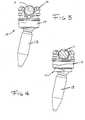
- Fig. 1illustrates a portion of the lumbar spine S with a unilateral orthopedic fixation device 10 in place to stabilize and fix the vertebra in relation to each other and the sacrum in order to maintain a more natural curvature.
- a bilateral installationcan be used, if deemed necessary.
- an elongated connector bar 11spans the discontinuity between the vertebra and bone screws 13.
- the barhas a circular cross section however, other shapes may be used, such as shown for the link 29 in Fig.13 .
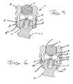
- the bone anchorshave an exterior helical thread 60, shown in Fig.s 5 - 6 , by which the bone screws 13 gain purchase in the cancellous bone through application of torque.
- the torqueis applied to the screws by the surgeon using a tool (not shown) that engages the recess 61 in the head 15 of the screw and rotates the screw about its longitudinal axis.
- the amount of torqueis critical to installation and the long life of the prosthesis in that too little does not secure the screw from loosening or backing out and too much causes the stripping of the thread path in the bone and loss of purchase.
- the surgeonattempts to apply the optimum torque when placing the screws in the bone and additional torque on the bone screw is to be avoided.
- the recess 61is accessible through the clamp body 12 which permits pre-assembly of the screw and clamp, if desired, before placement in the bone.
- the several bone screwsare threaded into the different vertebrae according to the anatomy of each vertebrae. This results in a series of screws without uniformity in angle or alignment.
- the connection between the head of the screws and the clamp bodiespivots or swivels to capture the connector rod.
- the rodmust be bent because the screws are so far out of line or the intended correction is so severe.
- a linkmay be used to secure the rod relative to the bone screw.
- the connector rod 11is secured to the bone screw by a linear motion which applies compressive force through clamp 12 to the rod 11 and the head 15 of the screw.
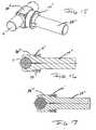
- the exterior walls 24 of the clamp body 12are illustrated as generally tubular with a receptacle 25, shown in Fig.8 , at one end and a slot 23 at the other end.
- the receptacleis of a size to accommodate the head 15 of the bone screw.
- the slot 23has upper and lower longitudinal ridges 17 and 18, respectively, to grip the connector rod 11.
- the head 15is spherical and the inside surface 16 of the receptacle is complementary to permit a universal or swivel connection.
- the orthopedic devicehas a low profile because the connector rod is recessed in the slot 23 of clamp 12.
- the exterior walls 24 of clamp 12may be tapered or otherwise shaped to provide a change in external diameter along the length.
- the walls 24also are relieved with circumferential slots 27 and 28, shown in Fig.s 8 - 9 , to increase the radial flexibility of the clamp.
- a compression ring 14is force fit on the exterior walls 24 of the clamp 12 by flexing the tubular walls.
- the compression ring 14is movable along the exterior walls from an open position to a closed position. The open position, as shown in Fig.s 5 , 18, and 20 , allows swiveling movement of the screw head and sliding movement of the connector rod within the clamp 12.
- the compression ring 14applies compressive forces between the clamp 12 and the rod 11 and screw 13 that immobilizes the connections.
- the compression ring 12has a skirt 26 with spaced inner annular ridges 20 and 22 which engage annular bulges 19 and 21, respectively, on the exterior walls 24 of clamp 12 in the closed position.
- the application of the compressive force that immobilizes the components of the orthopedic deviceis generated by a linear movement of the compression ring relative to the exterior walls of the clamp.
- This movement to the closed positionis accomplished using a simple telescoping instrument (not shown) engaging the clamp and the compression ring so that equal and opposite forces moves the ring without imparting stress to the screw.
- the clampmay be moved to the open position in the same manner.
- the link 29, shown in Fig. 13extends the range of the orthopedic device in situations where the connector rod cannot directly contact the slot 23 in the clamp 12.
- the linkmay come in different lengths or be customized to the size necessary for a particular patient.
- the link 29has an arm similar to the dimensions of a connector rod but of a trapezoidal shape though other shapes may be used.
- the armhas a journal 30 on one end.
- the journal 30is shown as a closed ring however, it may be discontinuous.
- the journalhas a threaded bore with a set screw 31 to secure the link to the connector rod.
- the other end of the linkis secured to the bone screw by the clamp 12 and compression ring 14.
- the link 29' armis the same or similar in shape to a connector rod.
- the linkhas a journal 30' with a set screw 31' to fix the connection with the connector rod 11.
- FIG.s 15, 16, and 17another link 29" is illustrated with a journal 30" at one end.
- the linkis similar to a connector rod.
- the journal 30"is a split sleeve with a compression ring 14' encircling the split sleeve.
- the compression ring 14'has an open position, shown in Fig. 17 , and a closed position, shown in Fig. 16 . After adjusting the connection between the link and the connector rod 11, the compression ring is moved to the closed position to secure the link to the connector rod.
- the other end of the link 29"is secured in the slot of the clamp 12 to complete the tightening of the orthopedic device.
- Fig.s 18 - 23illustrate embodiments of the orthopedic device 10 in which the clamp 12 includes a retainer preventing the inadvertent separation of the connector rod 11 from the clamp.
- the use of these clamps and retainersis discretionary with the surgeon.
- the exterior walls of the clamp 12extend above the slot 23 as opposing semi-circular projections.
- An exterior groove 41is formed in the semi-circular projections resulting in a terminal lip 42.
- a retainer ring 40is snapped into and held in place by the groove 41.
- Fig.s 20 and 21illustrate another retainer in the form of a clip 50 which extends across and covers the open slot 23.
- the ends 53 of the clipare reverse folded to snap over the lip 52 and seat into the groove 51.
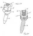
- Fig.s 22 and 23illustrate a clamp 12 ', not according to the present invention, with a bore 23' for passage of the connector rod 11.
- the bore 23'is intersected by a threaded passage 60 with a set screw retainer 61 for holding the connector rod 11 and the clamp 12' together.
- the compression ringswould be moved to the closed position locking the orientation of the rods and screws.
- the set screwswould then be tightened to fix the rod to the clamp. In this way, the torque of tightening the set screw would be absorbed by the rod.
- the clamp 12'is locked to the screw 13 by compression ring 14, shown in the closed position.
Landscapes
- Health & Medical Sciences (AREA)
- Orthopedic Medicine & Surgery (AREA)
- Life Sciences & Earth Sciences (AREA)
- Neurology (AREA)
- Surgery (AREA)
- Heart & Thoracic Surgery (AREA)
- Engineering & Computer Science (AREA)
- Biomedical Technology (AREA)
- Nuclear Medicine, Radiotherapy & Molecular Imaging (AREA)
- Medical Informatics (AREA)
- Molecular Biology (AREA)
- Animal Behavior & Ethology (AREA)
- General Health & Medical Sciences (AREA)
- Public Health (AREA)
- Veterinary Medicine (AREA)
- Surgical Instruments (AREA)
Description
- This invention relates to orthopedic surgery and, in particular, to devices and prosthesis for stabilizing and fixing bones and joints of the body.
- Published U. S. Application,
US 2003/0149487 A1, published Aug. 7, 2003 , teaches the use of a linear movement to apply compressive forces to connect components of an artificial hip joint. U. S. Patent No. 6,626,906 issued Set. 30, 2003 to Young teaches a spinal rod attached to a spinal anchor by a clamp. The clamp is tightened about the anchor by a collet screwed into the clamp. The rod is held in the clamp by a split ring that is reduced in size by the collet. The anchor is placed in the bone by torque and the collet is tightened by additional torque.- Patent No.
6,478,798 issued Nov. 12, 2002 to Howland andU. S. Patent No. 5,584;834 issued Dec. 17, 1996 to Errico et al teach a spinal rod coupled to several bone anchors by clamps that require additional torque to be applied to the assembly after the bone screw has been seated in the bone. - In normal practice, the bone screws are each anchored in the bone with a specific amount of torque that approaches the ultimate sustainable force between the screw threads and the bone. The bone screws are then connected together by a rod having sufficient stiffness to maintain the desired skeletal orientation. The connection between the rod and the bone screws must be strong enough to be immobile.
- All these prior art spinal fixation devices result in additional torque applied to the assembly, and thereby to the bone screw, to tighten and lock the rod to each of the bone screws. The additional load may strip the purchase between the bone and the threads of the bone screw. To prevent such a result, some tool must be used to counter the torque of locking the rod and the screws. The use of an anti-torqueing tool requires additional coordination by the surgeon or surgeons to prevent slippage.
US Patent No. 6,355,040 discloses an implant fixation system and locking mechanism for securing a rod to an implant.- What is needed in the art is a system for connecting a rod and an embedded bone screw using compressive forces rather than torque.
- There are many instances in which it is necessary to stabilise and fix bones and bone fragments in a particular spatial relationship to correct the location of skeletal components due to injury or disease. One group of devices employ a number of bone pins, anchors, or screws placed in bones across a discontinuity in the bone or bone fragments, such as a fracture, or adjacent vertebrae, or a joint, connected by a rod to maintain a predetermined spatial location of the bones. In some cases these devices may be temporary, with subsequent removal, or permanent, in the form of prosthesis. The devices may be internal or external of the body. The instant device may be used in these applications. However, the preferred embodiment is related to spinal fixation and the description is directed thereto by way of example and not limitation.
- The invention provides an orthopedic device for stabilizing bones, comprising a bone pin having a shank including external helical threading for penetrating a bone with a spherical head on one end and a clamp for locking said pin to an elongated connector rod, said head having a recess for engagement by a rotation tool, said clamp having a body including generally tubular exterior walls forming an inner receptacle at one end of the body that is adapted to enclose said head and is shaped complementary to said head to permit a swivel connection, a compression ring surrounding the outside of said exterior walls in one, open position allowing swiveling movement of the head and sliding movement of the connector rod within the clamp, a slot through said exterior walls of said body at the other end of the body opposite said receptacle, said slot including upper and lower longitudinal ridges adapted to grip said connector rod, said compression ring linearly movable along said outside of said exterior walls to a second, closed position whereby said compression ring is positioned about said exterior walls of said receptacle such that said exterior walls and said slot exert compressive force adapted to securely lock said clamp about the head and the connector rod, wherein the compression ring comprises a skirt having spaced inner annular ridges that engage annular bulges on the exterior walls of the clamp when the compression ring is in the closed position.
Fig. 1 is a perspective of a portion of the spine with the orthopedic device of this invention in place;Fig. 2 is a perspective of one embodiment of the orthopedic device of this invention;Fig. 3 is an end view, partially in section, of the orthopedic device of this invention with the compression ring in the open position;Fig. 4 is an end view, partially in section, of the orthopedic device of this invention with the compression ring in the closed position;Fig. 5 is a cross section ofFig. 3 ;Fig. 6 is a cross section ofFig. 4 ;Fig. 7 is a top plan view of the clamp body of this invention;Fig. 8 is a side view, partially in section, of the clamp body of this invention;Fig. 9 is a perspective of the clamp body of this invention;Fig. 10 is a perspective of the compression ring of this invnetion;Fig. 11 is a top view of the compression ring of this invention;Fig. 12 is a cross section of the compression ring of this invention;Fig. 13 is a perspective of another embodiment of this invention;Fig. 14 is a perspective of another embodiment of this invention;Fig. 15 is a perspective of another embodiment of this invention;Fig. 16 is a cross section ofFig. 15 showing the compression ring in the open position;Fig. 17 is a cross section ofFig. 15 showing the compression ring in the closed position;Fig. 18 is a perspective of another embodiment of this invention with the compression ring in the open position;Fig. 19 is a side view ofFig. 18 with the compression ring in the closed position;Fig. 20 is a perspective of another embodiment of this invention with the compression ring in the open position;Fig. 21 is a side view ofFig. 20 with the compression ring in the closed position;Fig. 22 is a perspective of another clamp; andFig. 23 is a cross section ofFig. 22 .Fig. 1 illustrates a portion of the lumbar spineS with a unilateralorthopedic fixation device 10 in place to stabilize and fix the vertebra in relation to each other and the sacrum in order to maintain a more natural curvature. A bilateral installation can be used, if deemed necessary. As shown in more detail inFig. 2 , anelongated connector bar 11 spans the discontinuity between the vertebra andbone screws 13. As shown, the bar has a circular cross section however, other shapes may be used, such as shown for thelink 29 inFig.13 . The bone anchors have an exteriorhelical thread 60, shown inFig.s 5 - 6 , by which thebone screws 13 gain purchase in the cancellous bone through application of torque.- The torque is applied to the screws by the surgeon using a tool (not shown) that engages the
recess 61 in the head15 of the screw and rotates the screw about its longitudinal axis. The amount of torque is critical to installation and the long life of the prosthesis in that too little does not secure the screw from loosening or backing out and too much causes the stripping of the thread path in the bone and loss of purchase. The surgeon attempts to apply the optimum torque when placing the screws in the bone and additional torque on the bone screw is to be avoided. As shown inFig.s 5 and 6 , therecess 61 is accessible through theclamp body 12 which permits pre-assembly of the screw and clamp, if desired, before placement in the bone. - During the spinal fixation, the several bone screws are threaded into the different vertebrae according to the anatomy of each vertebrae. This results in a series of screws without uniformity in angle or alignment. To compensate for these anomalies, the connection between the head of the screws and the clamp bodies pivots or swivels to capture the connector rod. In some instances, the rod must be bent because the screws are so far out of line or the intended correction is so severe. In other cases, a link may be used to secure the rod relative to the bone screw. To avoid application of any more torque to the bone screw, the
connector rod 11 is secured to the bone screw by a linear motion which applies compressive force throughclamp 12 to therod 11 and the head15 of the screw. - The
exterior walls 24 of theclamp body 12 are illustrated as generally tubular with areceptacle 25, shown inFig.8 , at one end and aslot 23 at the other end. The receptacle is of a size to accommodate the head15 of the bone screw. Theslot 23 has upper and lowerlongitudinal ridges connector rod 11. As shown inFig.s 5 and 6 , the head15 is spherical and the inside surface16 of the receptacle is complementary to permit a universal or swivel connection. The orthopedic device has a low profile because the connector rod is recessed in theslot 23 ofclamp 12. - The
exterior walls 24 ofclamp 12 may be tapered or otherwise shaped to provide a change in external diameter along the length. Thewalls 24 also are relieved withcircumferential slots 27 and28, shown inFig.s 8 - 9 , to increase the radial flexibility of the clamp. Acompression ring 14 is force fit on theexterior walls 24 of theclamp 12 by flexing the tubular walls. Thecompression ring 14 is movable along the exterior walls from an open position to a closed position. The open position, as shown inFig.s 5 ,18, and 20 , allows swiveling movement of the screw head and sliding movement of the connector rod within theclamp 12. In the closed position, shown inFig.s 6 ,19 and 21 , thecompression ring 14 applies compressive forces between theclamp 12 and therod 11 and screw13 that immobilizes the connections. Thecompression ring 12 has askirt 26 with spaced innerannular ridges annular bulges exterior walls 24 ofclamp 12 in the closed position. - The application of the compressive force that immobilizes the components of the orthopedic device is generated by a linear movement of the compression ring relative to the exterior walls of the clamp. This movement to the closed position is accomplished using a simple telescoping instrument (not shown) engaging the clamp and the compression ring so that equal and opposite forces moves the ring without imparting stress to the screw. In the event of remedial surgery, the clamp may be moved to the open position in the same manner.
- The
link 29, shown inFig. 13 , extends the range of the orthopedic device in situations where the connector rod cannot directly contact theslot 23 in theclamp 12. The link may come in different lengths or be customized to the size necessary for a particular patient. Thelink 29 has an arm similar to the dimensions of a connector rod but of a trapezoidal shape though other shapes may be used. The arm has ajournal 30 on one end. Thejournal 30 is shown as a closed ring however, it may be discontinuous. The journal has a threaded bore with aset screw 31 to secure the link to the connector rod. The other end of the link is secured to the bone screw by theclamp 12 andcompression ring 14. InFig. 14 , the link29' arm is the same or similar in shape to a connector rod. The link has a journal30' with a set screw31' to fix the connection with theconnector rod 11. - In
Fig.s 15, 16, and 17 anotherlink 29" is illustrated with ajournal 30" at one end. The link is similar to a connector rod. Thejournal 30" is a split sleeve with a compression ring14' encircling the split sleeve. The compression ring14' has an open position, shown inFig. 17 , and a closed position, shown inFig. 16 . After adjusting the connection between the link and theconnector rod 11, the compression ring is moved to the closed position to secure the link to the connector rod. The other end of thelink 29" is secured in the slot of theclamp 12 to complete the tightening of the orthopedic device. Fig.s 18 - 23 illustrate embodiments of theorthopedic device 10 in which theclamp 12 includes a retainer preventing the inadvertent separation of theconnector rod 11 from the clamp. The use of these clamps and retainers is discretionary with the surgeon. InFig.s 18 and 19 , the exterior walls of theclamp 12 extend above theslot 23 as opposing semi-circular projections. Anexterior groove 41 is formed in the semi-circular projections resulting in aterminal lip 42. A retainer ring40 is snapped into and held in place by thegroove 41.Fig.s 20 and 21 illustrate another retainer in the form of aclip 50 which extends across and covers theopen slot 23. The ends53 of the clip are reverse folded to snap over thelip 52 and seat into thegroove 51.Fig.s 22 and 23 illustrate a clamp12', not according to the present invention, with a bore23' for passage of theconnector rod 11. The bore23' is intersected by a threadedpassage 60 with aset screw retainer 61 for holding theconnector rod 11 and the clamp12' together. After therod 11 is passed through the clamps of an orthopedic device, the compression rings would be moved to the closed position locking the orientation of the rods and screws. The set screws would then be tightened to fix the rod to the clamp. In this way, the torque of tightening the set screw would be absorbed by the rod. The clamp12' is locked to thescrew 13 bycompression ring 14, shown in the closed position.- A number of embodiments of the present invention have been described. Nevertheless, it will be understood that various modifications may be made without departing from the scope of the invention. Accordingly, it is to be understood that the invention is not to be limited by the specific illustrated embodiment but only by the scope of the appended claims.
Claims (5)
- An orthopedic device (10) for stabilizing bones, comprising a bone pin (13) having a shank including external helical threading (60) for penetrating a bone with a spherical head (15) on one end and a clamp (12) for locking said pin to an elongated connector rod (11), said head having a recess (61) for engagement by a rotation tool, said clamp having a body including generally tubular exterior walls (24) forming an inner receptacle (25) at one end of the body that is adapted to enclose said head and is shaped complementary to said head to permit a swivel connection, a compression ring (14) surrounding the outside of said exterior walls in one, open position allowing swiveling movement of the head and sliding movement of the connector rod within the clamp, a slot (23) through said exterior walls of said body at the other end of the body opposite said receptacle, said slot including upper and lower longitudinal ridges (17, 18) adapted to grip said connector rod, said compression ring (14) linearly movable along said outside of said exterior walls (24) to a second, closed position whereby said compression ring is positioned about said exterior walls of said receptacle such that said exterior walls and said slot exert compressive force adapted to securely lock said clamp (12) about the head (15) and the connector rod (11), wherein the compression ring comprises a skirt (26) having spaced inner annular ridges (20, 22) that engage annular bulges (19, 21) on the exterior walls of the clamp when the compression ring is in the closed position.
- An orthopedic device according to claim 1, wherein the clamp and the compression ring are adapted for engagement with a telescoping instrument that moves the compression ring from the open to the closed position without imparting stress to the bone pin.
- An orthopedic device according to claim 1, wherein the clamp and the compression ring are adapted for engagement with a telescoping instrument that moves the compression ring from the closed to the open position without imparting stress to the bone pin.
- An orthopedic device according to claim 1, wherein said connector rod is adapted to be connected with a plurality of links and bone pins along the length thereof, said connector rod and said plurality of bone pins adapted to stabilize bones in a fixed position.
- An orthopedic device according to claim 1, wherein the exterior walls of the clamp are relieved with circumferential slots (27, 28) to increase the radial flexibility of the clamp.
Applications Claiming Priority (2)
| Application Number | Priority Date | Filing Date | Title |
|---|---|---|---|
| US10/701,349US7090674B2 (en) | 2003-11-03 | 2003-11-03 | Bone fixation system with low profile fastener |
| EP04800758AEP1682016B1 (en) | 2003-11-03 | 2004-11-03 | Bone fixation system with low profile fastener |
Related Parent Applications (2)
| Application Number | Title | Priority Date | Filing Date |
|---|---|---|---|
| EP04800758.7Division | 2004-11-03 | ||
| EP04800758ADivisionEP1682016B1 (en) | 2003-11-03 | 2004-11-03 | Bone fixation system with low profile fastener |
Publications (2)
| Publication Number | Publication Date |
|---|---|
| EP2371312A1 EP2371312A1 (en) | 2011-10-05 |
| EP2371312B1true EP2371312B1 (en) | 2014-12-17 |
Family
ID=34551408
Family Applications (2)
| Application Number | Title | Priority Date | Filing Date |
|---|---|---|---|
| EP04800758AExpired - LifetimeEP1682016B1 (en) | 2003-11-03 | 2004-11-03 | Bone fixation system with low profile fastener |
| EP11169372.7AExpired - LifetimeEP2371312B1 (en) | 2003-11-03 | 2004-11-03 | Bone fixation system with low profile fastener |
Family Applications Before (1)
| Application Number | Title | Priority Date | Filing Date |
|---|---|---|---|
| EP04800758AExpired - LifetimeEP1682016B1 (en) | 2003-11-03 | 2004-11-03 | Bone fixation system with low profile fastener |
Country Status (7)
| Country | Link |
|---|---|
| US (2) | US7090674B2 (en) |
| EP (2) | EP1682016B1 (en) |
| JP (1) | JP5081452B2 (en) |
| AU (1) | AU2004285611B2 (en) |
| CA (1) | CA2544021C (en) |
| ES (1) | ES2531041T3 (en) |
| WO (1) | WO2005041821A2 (en) |
Families Citing this family (189)
| Publication number | Priority date | Publication date | Assignee | Title |
|---|---|---|---|---|
| US7833250B2 (en) | 2004-11-10 | 2010-11-16 | Jackson Roger P | Polyaxial bone screw with helically wound capture connection |
| US8377100B2 (en) | 2000-12-08 | 2013-02-19 | Roger P. Jackson | Closure for open-headed medical implant |
| US6726689B2 (en) | 2002-09-06 | 2004-04-27 | Roger P. Jackson | Helical interlocking mating guide and advancement structure |
| US10258382B2 (en) | 2007-01-18 | 2019-04-16 | Roger P. Jackson | Rod-cord dynamic connection assemblies with slidable bone anchor attachment members along the cord |
| US8292926B2 (en) | 2005-09-30 | 2012-10-23 | Jackson Roger P | Dynamic stabilization connecting member with elastic core and outer sleeve |
| US7862587B2 (en) | 2004-02-27 | 2011-01-04 | Jackson Roger P | Dynamic stabilization assemblies, tool set and method |
| US10729469B2 (en) | 2006-01-09 | 2020-08-04 | Roger P. Jackson | Flexible spinal stabilization assembly with spacer having off-axis core member |
| US8353932B2 (en)* | 2005-09-30 | 2013-01-15 | Jackson Roger P | Polyaxial bone anchor assembly with one-piece closure, pressure insert and plastic elongate member |
| JP4130411B2 (en)* | 2002-02-11 | 2008-08-06 | ジンテーズ ゲゼルシャフト ミト ベシュレンクテル ハフツング | Device for joining the vertical support and bone |
| US8282673B2 (en) | 2002-09-06 | 2012-10-09 | Jackson Roger P | Anti-splay medical implant closure with multi-surface removal aperture |
| US8257402B2 (en) | 2002-09-06 | 2012-09-04 | Jackson Roger P | Closure for rod receiving orthopedic implant having left handed thread removal |
| WO2006052796A2 (en) | 2004-11-10 | 2006-05-18 | Jackson Roger P | Helical guide and advancement flange with break-off extensions |
| US8876868B2 (en) | 2002-09-06 | 2014-11-04 | Roger P. Jackson | Helical guide and advancement flange with radially loaded lip |
| US6716214B1 (en) | 2003-06-18 | 2004-04-06 | Roger P. Jackson | Polyaxial bone screw with spline capture connection |
| US7621918B2 (en) | 2004-11-23 | 2009-11-24 | Jackson Roger P | Spinal fixation tool set and method |
| US7377923B2 (en) | 2003-05-22 | 2008-05-27 | Alphatec Spine, Inc. | Variable angle spinal screw assembly |
| US8366753B2 (en) | 2003-06-18 | 2013-02-05 | Jackson Roger P | Polyaxial bone screw assembly with fixed retaining structure |
| US8926670B2 (en) | 2003-06-18 | 2015-01-06 | Roger P. Jackson | Polyaxial bone screw assembly |
| US7967850B2 (en) | 2003-06-18 | 2011-06-28 | Jackson Roger P | Polyaxial bone anchor with helical capture connection, insert and dual locking assembly |
| US7776067B2 (en) | 2005-05-27 | 2010-08-17 | Jackson Roger P | Polyaxial bone screw with shank articulation pressure insert and method |
| US7766915B2 (en) | 2004-02-27 | 2010-08-03 | Jackson Roger P | Dynamic fixation assemblies with inner core and outer coil-like member |
| US8398682B2 (en) | 2003-06-18 | 2013-03-19 | Roger P. Jackson | Polyaxial bone screw assembly |
| US8377102B2 (en) | 2003-06-18 | 2013-02-19 | Roger P. Jackson | Polyaxial bone anchor with spline capture connection and lower pressure insert |
| US8137386B2 (en) | 2003-08-28 | 2012-03-20 | Jackson Roger P | Polyaxial bone screw apparatus |
| US8257398B2 (en) | 2003-06-18 | 2012-09-04 | Jackson Roger P | Polyaxial bone screw with cam capture |
| US7588575B2 (en) | 2003-10-21 | 2009-09-15 | Innovative Spinal Technologies | Extension for use with stabilization systems for internal structures |
| US7967826B2 (en)* | 2003-10-21 | 2011-06-28 | Theken Spine, Llc | Connector transfer tool for internal structure stabilization systems |
| US7527638B2 (en) | 2003-12-16 | 2009-05-05 | Depuy Spine, Inc. | Methods and devices for minimally invasive spinal fixation element placement |
| US11419642B2 (en) | 2003-12-16 | 2022-08-23 | Medos International Sarl | Percutaneous access devices and bone anchor assemblies |
| US7179261B2 (en) | 2003-12-16 | 2007-02-20 | Depuy Spine, Inc. | Percutaneous access devices and bone anchor assemblies |
| US8152810B2 (en) | 2004-11-23 | 2012-04-10 | Jackson Roger P | Spinal fixation tool set and method |
| JP2007525274A (en) | 2004-02-27 | 2007-09-06 | ロジャー・ピー・ジャクソン | Orthopedic implant rod reduction instrument set and method |
| US7160300B2 (en) | 2004-02-27 | 2007-01-09 | Jackson Roger P | Orthopedic implant rod reduction tool set and method |
| US11241261B2 (en) | 2005-09-30 | 2022-02-08 | Roger P Jackson | Apparatus and method for soft spinal stabilization using a tensionable cord and releasable end structure |
| US7214227B2 (en)* | 2004-03-22 | 2007-05-08 | Innovative Spinal Technologies | Closure member for a medical implant device |
| US7901435B2 (en)* | 2004-05-28 | 2011-03-08 | Depuy Spine, Inc. | Anchoring systems and methods for correcting spinal deformities |
| US7651502B2 (en) | 2004-09-24 | 2010-01-26 | Jackson Roger P | Spinal fixation tool set and method for rod reduction and fastener insertion |
| WO2006047711A2 (en) | 2004-10-25 | 2006-05-04 | Alphaspine, Inc. | Pedicle screw systems and methods |
| US7604655B2 (en) | 2004-10-25 | 2009-10-20 | X-Spine Systems, Inc. | Bone fixation system and method for using the same |
| US8926672B2 (en) | 2004-11-10 | 2015-01-06 | Roger P. Jackson | Splay control closure for open bone anchor |
| US8444681B2 (en) | 2009-06-15 | 2013-05-21 | Roger P. Jackson | Polyaxial bone anchor with pop-on shank, friction fit retainer and winged insert |
| US9216041B2 (en) | 2009-06-15 | 2015-12-22 | Roger P. Jackson | Spinal connecting members with tensioned cords and rigid sleeves for engaging compression inserts |
| WO2006057837A1 (en) | 2004-11-23 | 2006-06-01 | Jackson Roger P | Spinal fixation tool attachment structure |
| US8308782B2 (en) | 2004-11-23 | 2012-11-13 | Jackson Roger P | Bone anchors with longitudinal connecting member engaging inserts and closures for fixation and optional angulation |
| US9980753B2 (en) | 2009-06-15 | 2018-05-29 | Roger P Jackson | pivotal anchor with snap-in-place insert having rotation blocking extensions |
| US7875065B2 (en) | 2004-11-23 | 2011-01-25 | Jackson Roger P | Polyaxial bone screw with multi-part shank retainer and pressure insert |
| US9168069B2 (en) | 2009-06-15 | 2015-10-27 | Roger P. Jackson | Polyaxial bone anchor with pop-on shank and winged insert with lower skirt for engaging a friction fit retainer |
| WO2006058221A2 (en) | 2004-11-24 | 2006-06-01 | Abdou Samy M | Devices and methods for inter-vertebral orthopedic device placement |
| AU2006214001B2 (en) | 2005-02-18 | 2011-05-26 | Samy Abdou | Devices and methods for dynamic fixation of skeletal structure |
| US10076361B2 (en) | 2005-02-22 | 2018-09-18 | Roger P. Jackson | Polyaxial bone screw with spherical capture, compression and alignment and retention structures |
| US7901437B2 (en) | 2007-01-26 | 2011-03-08 | Jackson Roger P | Dynamic stabilization member with molded connection |
| EP1858422A4 (en)* | 2005-02-23 | 2011-12-28 | Pioneer Surgical Technology Inc | Minimally invasive surgical system |
| WO2008024937A2 (en) | 2006-08-23 | 2008-02-28 | Pioneer Surgical Technology, Inc. | Minimally invasive surgical system |
| WO2008137933A1 (en)* | 2005-05-25 | 2008-11-13 | Alpinespine Llc | Low rider pedicle screw system |
| WO2006127992A2 (en)* | 2005-05-25 | 2006-11-30 | Alphaspine, Inc. | Low profile pedicle screw and rod assembly |
| US7717943B2 (en) | 2005-07-29 | 2010-05-18 | X-Spine Systems, Inc. | Capless multiaxial screw and spinal fixation assembly and method |
| US7988694B2 (en)* | 2005-09-29 | 2011-08-02 | K2M, Inc. | Spinal fixation system having locking and unlocking devices for use with a multi-planar, taper lock screw |
| US8105368B2 (en) | 2005-09-30 | 2012-01-31 | Jackson Roger P | Dynamic stabilization connecting member with slitted core and outer sleeve |
| WO2007041702A2 (en) | 2005-10-04 | 2007-04-12 | Alphaspine, Inc. | Pedicle screw system with provisional locking aspects |
| US8097025B2 (en)* | 2005-10-25 | 2012-01-17 | X-Spine Systems, Inc. | Pedicle screw system configured to receive a straight or curved rod |
| US7704271B2 (en) | 2005-12-19 | 2010-04-27 | Abdou M Samy | Devices and methods for inter-vertebral orthopedic device placement |
| US7833252B2 (en) | 2006-01-27 | 2010-11-16 | Warsaw Orthopedic, Inc. | Pivoting joints for spinal implants including designed resistance to motion and methods of use |
| US7722652B2 (en) | 2006-01-27 | 2010-05-25 | Warsaw Orthopedic, Inc. | Pivoting joints for spinal implants including designed resistance to motion and methods of use |
| US8057519B2 (en)* | 2006-01-27 | 2011-11-15 | Warsaw Orthopedic, Inc. | Multi-axial screw assembly |
| CA2647026A1 (en)* | 2006-03-22 | 2008-08-28 | Pioneer Surgical Technology, Inc. | Low top bone fixation system and method for using the same |
| US8435267B2 (en)* | 2006-04-24 | 2013-05-07 | Spinefrontier Inc | Spine fixation method and apparatus |
| US8133262B2 (en)* | 2006-04-28 | 2012-03-13 | Depuy Spine, Inc. | Large diameter bone anchor assembly |
| US20080015576A1 (en)* | 2006-04-28 | 2008-01-17 | Whipple Dale E | Large diameter bone anchor assembly |
| US8361129B2 (en) | 2006-04-28 | 2013-01-29 | Depuy Spine, Inc. | Large diameter bone anchor assembly |
| US8162991B2 (en)* | 2006-07-27 | 2012-04-24 | K2M, Inc. | Multi-planar, taper lock screw |
| US8062340B2 (en)* | 2006-08-16 | 2011-11-22 | Pioneer Surgical Technology, Inc. | Spinal rod anchor device and method |
| WO2008024373A2 (en)* | 2006-08-21 | 2008-02-28 | Abdou M Samy | Bone screw systems and methods of use |
| US7699876B2 (en)* | 2006-11-08 | 2010-04-20 | Ebi, Llc | Multi-axial bone fixation apparatus |
| CA2670988C (en) | 2006-12-08 | 2014-03-25 | Roger P. Jackson | Tool system for dynamic spinal implants |
| US8475498B2 (en) | 2007-01-18 | 2013-07-02 | Roger P. Jackson | Dynamic stabilization connecting member with cord connection |
| US8366745B2 (en) | 2007-05-01 | 2013-02-05 | Jackson Roger P | Dynamic stabilization assembly having pre-compressed spacers with differential displacements |
| US10792074B2 (en) | 2007-01-22 | 2020-10-06 | Roger P. Jackson | Pivotal bone anchor assemly with twist-in-place friction fit insert |
| US8568453B2 (en) | 2007-01-29 | 2013-10-29 | Samy Abdou | Spinal stabilization systems and methods of use |
| US20080200956A1 (en)* | 2007-02-19 | 2008-08-21 | Tutela Medicus, Llc | Low Profile Orthopedic Fastener Assembly Having Enhanced Flexibility |
| US7842074B2 (en) | 2007-02-26 | 2010-11-30 | Abdou M Samy | Spinal stabilization systems and methods of use |
| US8979904B2 (en) | 2007-05-01 | 2015-03-17 | Roger P Jackson | Connecting member with tensioned cord, low profile rigid sleeve and spacer with torsion control |
| US10383660B2 (en) | 2007-05-01 | 2019-08-20 | Roger P. Jackson | Soft stabilization assemblies with pretensioned cords |
| US20080312697A1 (en)* | 2007-06-15 | 2008-12-18 | Robert Reid, Inc. | System and Method for Polyaxially Adjustable Bone Anchorage |
| US8361126B2 (en) | 2007-07-03 | 2013-01-29 | Pioneer Surgical Technology, Inc. | Bone plate system |
| US8623019B2 (en) | 2007-07-03 | 2014-01-07 | Pioneer Surgical Technology, Inc. | Bone plate system |
| US8961523B2 (en) | 2007-07-13 | 2015-02-24 | K2M, Inc. | Rod reduction device and method of use |
| DE102007033219B4 (en)* | 2007-07-17 | 2010-10-07 | Aesculap Ag | Orthopedic retention system |
| ES2348814T3 (en)* | 2007-07-31 | 2010-12-15 | Biedermann Motech Gmbh | ANCHORAGE DEVICE Ã “SEO. |
| US20090069852A1 (en)* | 2007-09-06 | 2009-03-12 | Warsaw Orthopedic, Inc. | Multi-Axial Bone Anchor Assembly |
| US8038701B2 (en)* | 2007-10-22 | 2011-10-18 | K2M, Inc. | Uni-planar, taper lock bone screw |
| US20090105756A1 (en)* | 2007-10-23 | 2009-04-23 | Marc Richelsoph | Spinal implant |
| US8287576B2 (en)* | 2007-10-23 | 2012-10-16 | K2M, Inc. | Mono-axial, taper lock bone screw |
| US8398683B2 (en)* | 2007-10-23 | 2013-03-19 | Pioneer Surgical Technology, Inc. | Rod coupling assembly and methods for bone fixation |
| JP5651472B2 (en)* | 2007-10-23 | 2015-01-14 | ケー2エム, インコーポレイテッド | Posterior pedicle screw with taper lock |
| TWI387283B (en)* | 2008-04-25 | 2013-02-21 | Univ Nat Taiwan | Wireless smart controlling display panel |
| US20090292308A1 (en)* | 2008-05-22 | 2009-11-26 | K2M, Inc. | Spinal fixation system |
| AU2009257412B2 (en) | 2008-06-11 | 2014-08-14 | K2M, Inc. | Rod reduction device |
| US20100004693A1 (en)* | 2008-07-01 | 2010-01-07 | Peter Thomas Miller | Cam locking spine stabilization system and method |
| WO2010002466A1 (en)* | 2008-07-01 | 2010-01-07 | Alphatec Spine, Inc. | A screw assembly |
| US8118837B2 (en)* | 2008-07-03 | 2012-02-21 | Zimmer Spine, Inc. | Tapered-lock spinal rod connectors and methods for use |
| EP2339976B1 (en) | 2008-07-09 | 2016-03-16 | Icon Orthopaedic Concepts, LLC | Ankle arthrodesis nail and outrigger assembly |
| US8414584B2 (en) | 2008-07-09 | 2013-04-09 | Icon Orthopaedic Concepts, Llc | Ankle arthrodesis nail and outrigger assembly |
| US8197512B1 (en)* | 2008-07-16 | 2012-06-12 | Zimmer Spine, Inc. | System and method for spine stabilization using resilient inserts |
| US8167914B1 (en) | 2008-07-16 | 2012-05-01 | Zimmer Spine, Inc. | Locking insert for spine stabilization and method of use |
| AU2010260521C1 (en) | 2008-08-01 | 2013-08-01 | Roger P. Jackson | Longitudinal connecting member with sleeved tensioned cords |
| US8167908B2 (en)* | 2008-08-29 | 2012-05-01 | Zimmer Spine, Inc. | Polyaxial transverse connector |
| US9603629B2 (en) | 2008-09-09 | 2017-03-28 | Intelligent Implant Systems Llc | Polyaxial screw assembly |
| US20100087873A1 (en)* | 2008-10-06 | 2010-04-08 | Warsaw Orthopedics, Inc. | Surgical Connectors for Attaching an Elongated Member to a Bone |
| US8506601B2 (en) | 2008-10-14 | 2013-08-13 | Pioneer Surgical Technology, Inc. | Low profile dual locking fixation system and offset anchor member |
| FR2937531B1 (en)* | 2008-10-23 | 2016-01-29 | Lotfi Miladi | SPINAL OSTEOSYNTHESIS SYSTEM |
| US20100114171A1 (en)* | 2008-11-05 | 2010-05-06 | K2M, Inc. | Multi-planar spinal fixation assembly with locking element |
| US8696717B2 (en)* | 2008-11-05 | 2014-04-15 | K2M, Inc. | Multi-planar, taper lock screw with additional lock |
| ES2403194T3 (en)* | 2008-11-28 | 2013-05-16 | Biedermann Technologies Gmbh & Co. Kg | Receiving component to receive a rod for coupling with a bone anchoring element and a bone anchoring system with this receiving component |
| ES2375879T3 (en)* | 2008-12-23 | 2012-03-07 | Biedermann Motech Gmbh | RECEPTION AREA OF A ROD FOR COUPLING THE ROD IN AN BONE ANCHORAGE ELEMENT AND BONE ANCHORAGE DEVICE WITH SUCH RECEPTION AREA. |
| ES2423676T3 (en) | 2008-12-29 | 2013-09-23 | Biedermann Technologies Gmbh & Co. Kg | Housing piece to accommodate a rod in order to couple the rod to a bone anchoring element, and bone anchoring device with such a housing piece |
| ES2378588T3 (en) | 2008-12-30 | 2012-04-16 | Biedermann Motech Gmbh | Receiving part for receiving a rod for coupling the rod in a bone anchoring element and bone anchoring device with such receiving part |
| US8636778B2 (en)* | 2009-02-11 | 2014-01-28 | Pioneer Surgical Technology, Inc. | Wide angulation coupling members for bone fixation system |
| EP2249725B1 (en)* | 2009-02-19 | 2015-06-10 | Ulrich GmbH & Co. KG | Device for stabilizing the spinal column |
| CN101917919B (en)* | 2009-02-19 | 2014-10-22 | 乌尔里克两合公司 | Device for stabilizing the spinal column |
| US8091305B2 (en)* | 2009-02-27 | 2012-01-10 | Skeeter Jane A | Recycled glass structural and decorative barrier or building, lighting and furniture component |
| US9668771B2 (en) | 2009-06-15 | 2017-06-06 | Roger P Jackson | Soft stabilization assemblies with off-set connector |
| CN103826560A (en) | 2009-06-15 | 2014-05-28 | 罗杰.P.杰克逊 | Polyaxial Bone Anchor with Socket Stem and Winged Inserts with Friction Fit Compression Collars |
| US11229457B2 (en) | 2009-06-15 | 2022-01-25 | Roger P. Jackson | Pivotal bone anchor assembly with insert tool deployment |
| US8998959B2 (en) | 2009-06-15 | 2015-04-07 | Roger P Jackson | Polyaxial bone anchors with pop-on shank, fully constrained friction fit retainer and lock and release insert |
| EP2485654B1 (en) | 2009-10-05 | 2021-05-05 | Jackson P. Roger | Polyaxial bone anchor with non-pivotable retainer and pop-on shank, some with friction fit |
| US8361123B2 (en) | 2009-10-16 | 2013-01-29 | Depuy Spine, Inc. | Bone anchor assemblies and methods of manufacturing and use thereof |
| US9011507B2 (en) | 2009-10-28 | 2015-04-21 | Orthopro Llc | Compression plate kit and methods for repairing bone discontinuities |
| US8162996B2 (en)* | 2009-10-28 | 2012-04-24 | Orthopro Llc | Methods for repairing bone discontinuities |
| WO2011063410A1 (en)* | 2009-11-23 | 2011-05-26 | Felix Quevedo | Cam lock pedicle screw |
| US8764806B2 (en) | 2009-12-07 | 2014-07-01 | Samy Abdou | Devices and methods for minimally invasive spinal stabilization and instrumentation |
| US9050138B2 (en) | 2010-01-28 | 2015-06-09 | Warsaw Orthopedic, Inc. | Vertebral rod connector and methods of use |
| US20110218574A1 (en)* | 2010-03-03 | 2011-09-08 | Warsaw Orthopedic, Inc. | Dynamic vertebral construct |
| EP2384709B1 (en) | 2010-05-05 | 2012-09-05 | Biedermann Technologies GmbH & Co. KG | Receiving part for receiving a rod for coupling the rod to a bone anchoring element, bone anchoring device, method and tool for assembling the same |
| US12383311B2 (en) | 2010-05-14 | 2025-08-12 | Roger P. Jackson | Pivotal bone anchor assembly and method for use thereof |
| AU2011299558A1 (en) | 2010-09-08 | 2013-05-02 | Roger P. Jackson | Dynamic stabilization members with elastic and inelastic sections |
| AU2011324058A1 (en) | 2010-11-02 | 2013-06-20 | Roger P. Jackson | Polyaxial bone anchor with pop-on shank and pivotable retainer |
| EP2737864B1 (en)* | 2010-12-10 | 2017-04-12 | Biedermann Technologies GmbH & Co. KG | Receiving part for receiving a rod for coupling the rod to a bone anchoring element and a bone anchoring device |
| EP2462888B1 (en)* | 2010-12-10 | 2015-02-18 | Biedermann Technologies GmbH & Co. KG | Receiving part for receiving a rod for coupling the rod to a bone anchoring element and bone anchoring device with such a receiving part |
| US20120203281A1 (en)* | 2011-02-05 | 2012-08-09 | Alphatec Spine, Inc | Semi-rigid screw assembly |
| JP5865479B2 (en) | 2011-03-24 | 2016-02-17 | ロジャー・ピー・ジャクソン | Multiaxial bone anchor with compound joint and pop-mounted shank |
| US8845728B1 (en) | 2011-09-23 | 2014-09-30 | Samy Abdou | Spinal fixation devices and methods of use |
| EP2574297B1 (en)* | 2011-09-30 | 2015-11-11 | Biedermann Technologies GmbH & Co. KG | Bone anchoring device and tool cooperating with such a bone anchoring device |
| DE102011054203A1 (en) | 2011-10-05 | 2013-04-11 | Aesculap Ag | Readjustable polyaxial pedicle screw |
| US8758411B1 (en) | 2011-10-25 | 2014-06-24 | Nuvasive, Inc. | Implants and methods for treating spinal disorders |
| US9198769B2 (en) | 2011-12-23 | 2015-12-01 | Pioneer Surgical Technology, Inc. | Bone anchor assembly, bone plate system, and method |
| US8911479B2 (en) | 2012-01-10 | 2014-12-16 | Roger P. Jackson | Multi-start closures for open implants |
| US20130226240A1 (en) | 2012-02-22 | 2013-08-29 | Samy Abdou | Spinous process fixation devices and methods of use |
| ES2527766T3 (en)* | 2012-05-29 | 2015-01-29 | Biedermann Technologies Gmbh & Co. Kg | Receiver piece for receiving and housing a bar in order to couple it with a bone anchoring element, and bone anchoring device with such a receiving piece |
| EP2866705B1 (en)* | 2012-06-27 | 2017-05-31 | Warsaw Orthopedic, Inc. | Prosthesis for vertebral compression fracture |
| US9198767B2 (en) | 2012-08-28 | 2015-12-01 | Samy Abdou | Devices and methods for spinal stabilization and instrumentation |
| US9320617B2 (en) | 2012-10-22 | 2016-04-26 | Cogent Spine, LLC | Devices and methods for spinal stabilization and instrumentation |
| EP2911599B1 (en)* | 2012-10-23 | 2020-04-29 | Nexus Spine, L.L.C. | Surgical construct coupling system |
| US9186182B2 (en)* | 2012-11-13 | 2015-11-17 | K2M, Inc. | Spinal stabilization system |
| US8911478B2 (en) | 2012-11-21 | 2014-12-16 | Roger P. Jackson | Splay control closure for open bone anchor |
| US10058354B2 (en) | 2013-01-28 | 2018-08-28 | Roger P. Jackson | Pivotal bone anchor assembly with frictional shank head seating surfaces |
| US8852239B2 (en) | 2013-02-15 | 2014-10-07 | Roger P Jackson | Sagittal angle screw with integral shank and receiver |
| US9675386B2 (en) | 2013-03-11 | 2017-06-13 | K2M, Inc. | Flexible fastening system |
| US20140277155A1 (en) | 2013-03-14 | 2014-09-18 | K2M, Inc. | Taper lock hook |
| US20140277159A1 (en) | 2013-03-14 | 2014-09-18 | DePuy Synthes Products, LLC | Bottom-loading bone anchor assemblies |
| US9918746B2 (en) | 2013-09-01 | 2018-03-20 | Carbofix In Orthopedics Llc | Composite material spinal implant |
| US9044273B2 (en) | 2013-10-07 | 2015-06-02 | Intelligent Implant Systems, Llc | Polyaxial plate rod system and surgical procedure |
| US9566092B2 (en) | 2013-10-29 | 2017-02-14 | Roger P. Jackson | Cervical bone anchor with collet retainer and outer locking sleeve |
| US9649135B2 (en)* | 2013-11-27 | 2017-05-16 | Spinal Llc | Bottom loading low profile fixation system |
| US9717533B2 (en) | 2013-12-12 | 2017-08-01 | Roger P. Jackson | Bone anchor closure pivot-splay control flange form guide and advancement structure |
| US9451993B2 (en) | 2014-01-09 | 2016-09-27 | Roger P. Jackson | Bi-radial pop-on cervical bone anchor |
| US10918419B2 (en) | 2014-04-01 | 2021-02-16 | K2M, Inc. | Spinal fixation device |
| US10064658B2 (en) | 2014-06-04 | 2018-09-04 | Roger P. Jackson | Polyaxial bone anchor with insert guides |
| US9597119B2 (en) | 2014-06-04 | 2017-03-21 | Roger P. Jackson | Polyaxial bone anchor with polymer sleeve |
| EP3188678A1 (en)* | 2014-09-01 | 2017-07-12 | Carbofix In Orthopedics LLC | Composite material spinal implant |
| US9707013B2 (en)* | 2015-04-30 | 2017-07-18 | Warsaw Orthopedic, Inc. | Spinal implant system and methods of use |
| US10857003B1 (en) | 2015-10-14 | 2020-12-08 | Samy Abdou | Devices and methods for vertebral stabilization |
| EP3278750B1 (en) | 2016-08-04 | 2018-12-12 | Biedermann Technologies GmbH & Co. KG | Polyaxial bone anchoring device and system of an instrument and a polyaxial bone anchoring device |
| EP3287089B1 (en) | 2016-08-24 | 2019-07-24 | Biedermann Technologies GmbH & Co. KG | Polyaxial bone anchoring device and system of an instrument and a polyaxial bone anchoring device |
| EP3525699B1 (en) | 2016-10-11 | 2023-07-26 | K2M, Inc. | Spinal implant |
| US10744000B1 (en) | 2016-10-25 | 2020-08-18 | Samy Abdou | Devices and methods for vertebral bone realignment |
| US10973648B1 (en) | 2016-10-25 | 2021-04-13 | Samy Abdou | Devices and methods for vertebral bone realignment |
| US10485590B2 (en) | 2017-01-18 | 2019-11-26 | K2M, Inc. | Rod reducing device |
| US10610265B1 (en) | 2017-07-31 | 2020-04-07 | K2M, Inc. | Polyaxial bone screw with increased angulation |
| EP3476340B1 (en) | 2017-10-25 | 2021-06-02 | Biedermann Technologies GmbH & Co. KG | Polyaxial bone anchoring device |
| EP3536271B1 (en) | 2018-03-06 | 2022-05-04 | Biedermann Technologies GmbH & Co. KG | Polyaxial bone anchoring device and system of an instrument and a polyaxial bone anchoring device |
| US11179248B2 (en) | 2018-10-02 | 2021-11-23 | Samy Abdou | Devices and methods for spinal implantation |
| CN109394323A (en)* | 2018-12-25 | 2019-03-01 | 上海斯潘威生物技术有限公司 | A kind of self-locking Universal screw nail structure for internal fixation of spine |
| US11571244B2 (en)* | 2019-05-22 | 2023-02-07 | Nuvasive, Inc. | Posterior spinal fixation screws |
| EP3821834B1 (en)* | 2019-11-14 | 2024-05-01 | Biedermann Technologies GmbH & Co. KG | Receiving part for coupling a rod to a bone anchor |
| US11877779B2 (en) | 2020-03-26 | 2024-01-23 | Xtant Medical Holdings, Inc. | Bone plate system |
| EP4111992B1 (en)* | 2021-07-01 | 2024-01-31 | Biedermann Technologies GmbH & Co. KG | Bone anchoring device |
| US12245796B1 (en) | 2024-05-14 | 2025-03-11 | Complex Spinal, LLC | Spinal fixation system having a lockable connector |
| US12245794B1 (en) | 2024-05-14 | 2025-03-11 | Complex Spinal, LLC | Spinal fixation system having a low profile lockable connector |
| US12213704B1 (en)* | 2024-06-18 | 2025-02-04 | Complex Spinal, LLC | Modular spinal fixation screw |
Family Cites Families (66)
| Publication number | Priority date | Publication date | Assignee | Title |
|---|---|---|---|---|
| US37227A (en)* | 1862-12-23 | Improvement in holdbacks for carriages | ||
| US486196A (en)* | 1892-11-15 | Optarles henry ridsdale | ||
| US255248A (en)* | 1882-03-21 | Means for charging secondary batteries | ||
| US37665A (en)* | 1863-02-10 | Amos westcott | ||
| US590294A (en)* | 1897-09-21 | Nut-lock | ||
| US255428A (en)* | 1882-03-28 | Nut-lock | ||
| US4378187A (en)* | 1979-09-24 | 1983-03-29 | Fullerton Robert L | Quick-acting nut assembly |
| US4419026A (en)* | 1980-08-28 | 1983-12-06 | Alfonso Leto | Internal locking device for telescopic elements and method of making the same |
| DE3614101C1 (en)* | 1986-04-25 | 1987-10-22 | Juergen Prof Dr Med Harms | Pedicle screw |
| DE8704134U1 (en)* | 1987-03-19 | 1987-07-16 | Zielke, Klaus, Dr.med., 3590 Bad Wildungen | Implant designed as a distraction and compression rod |
| US4887595A (en)* | 1987-07-29 | 1989-12-19 | Acromed Corporation | Surgically implantable device for spinal columns |
| US4836196A (en)* | 1988-01-11 | 1989-06-06 | Acromed Corporation | Surgically implantable spinal correction system |
| US4887596A (en)* | 1988-03-02 | 1989-12-19 | Synthes (U.S.A.) | Open backed pedicle screw |
| US4950269A (en)* | 1988-06-13 | 1990-08-21 | Acromed Corporation | Spinal column fixation device |
| US5002542A (en)* | 1989-10-30 | 1991-03-26 | Synthes U.S.A. | Pedicle screw clamp |
| FR2657774B1 (en)* | 1990-02-08 | 1992-05-22 | Sofamor | SACRED TAKING SHOE FOR A SPINAL OSTEOSYNTHESIS DEVICE. |
| US5129900B1 (en)* | 1990-07-24 | 1998-12-29 | Acromed Corp | Spinal column retaining method and apparatus |
| US5110244A (en)* | 1991-08-27 | 1992-05-05 | Caterpillar Inc. | Fastener assembly |
| CH692542A5 (en) | 1991-09-18 | 2002-07-31 | Implant Innovations Inc | Device for reconstructing teeth. |
| US5427488A (en)* | 1991-11-06 | 1995-06-27 | Fullerton; Robert L. | Quick acting nut or coupling assembly |
| US5324150A (en) | 1991-11-06 | 1994-06-28 | Fullerton Robert L | Quick acting nut or coupling assembly |
| DE4307576C1 (en)* | 1993-03-10 | 1994-04-21 | Biedermann Motech Gmbh | Bone screw esp. for spinal column correction - has U=shaped holder section for receiving straight or bent rod |
| US6162234A (en)* | 1993-03-23 | 2000-12-19 | Freedland; Yosef | Adjustable button cinch anchor orthopedic fastener |
| US5487744A (en)* | 1993-04-08 | 1996-01-30 | Advanced Spine Fixation Systems, Inc. | Closed connector for spinal fixation systems |
| JP3683909B2 (en)* | 1993-10-08 | 2005-08-17 | ロゴジンスキ,チェーム | Device for treating spinal conditions |
| US5628740A (en)* | 1993-12-23 | 1997-05-13 | Mullane; Thomas S. | Articulating toggle bolt bone screw |
| US5653765A (en)* | 1994-07-01 | 1997-08-05 | Ortho Development Corporation | Modular prosthesis |
| US5591166A (en)* | 1995-03-27 | 1997-01-07 | Smith & Nephew Richards, Inc. | Multi angle bone bolt |
| US5569247A (en)* | 1995-03-27 | 1996-10-29 | Smith & Nephew Richards, Inc. | Enhanced variable angle bone bolt |
| JP3501542B2 (en)* | 1995-04-07 | 2004-03-02 | 富久 腰野 | Medical hard tissue replacements and artificial joints |
| US5669911A (en)* | 1995-04-13 | 1997-09-23 | Fastenetix, L.L.C. | Polyaxial pedicle screw |
| US5882350A (en)* | 1995-04-13 | 1999-03-16 | Fastenetix, Llc | Polyaxial pedicle screw having a threaded and tapered compression locking mechanism |
| US5613816A (en)* | 1995-06-09 | 1997-03-25 | Thread Technology, Inc. | Apparatus for rapidly engaging and disengaging threaded coupling members |
| US5733285A (en)* | 1995-07-13 | 1998-03-31 | Fastenetix, Llc | Polyaxial locking mechanism |
| US5549608A (en)* | 1995-07-13 | 1996-08-27 | Fastenetix, L.L.C. | Advanced polyaxial locking screw and coupling element device for use with rod fixation apparatus |
| US5584834A (en)* | 1995-07-13 | 1996-12-17 | Fastenetix, L.L.C. | Polyaxial locking screw and coupling element assembly for use with side loading rod fixation apparatus |
| US5683392A (en)* | 1995-10-17 | 1997-11-04 | Wright Medical Technology, Inc. | Multi-planar locking mechanism for bone fixation |
| US5800435A (en)* | 1996-10-09 | 1998-09-01 | Techsys, Llc | Modular spinal plate for use with modular polyaxial locking pedicle screws |
| US5800108A (en)* | 1996-10-09 | 1998-09-01 | Thread Technology, Inc. | Apparatus for rapidly engaging and disengaging threaded coupling members |
| US5863293A (en)* | 1996-10-18 | 1999-01-26 | Spinal Innovations | Spinal implant fixation assembly |
| US5964760A (en) | 1996-10-18 | 1999-10-12 | Spinal Innovations | Spinal implant fixation assembly |
| US6416515B1 (en)* | 1996-10-24 | 2002-07-09 | Spinal Concepts, Inc. | Spinal fixation system |
| US5728098A (en)* | 1996-11-07 | 1998-03-17 | Sdgi Holdings, Inc. | Multi-angle bone screw assembly using shape-memory technology |
| ES2191775T3 (en)* | 1996-12-12 | 2003-09-16 | Synthes Ag | DEVICE FOR CONNECTING A LONGITUDINAL SUPPORT WITH A PEDICULAR SCREW. |
| US5788443A (en)* | 1997-03-13 | 1998-08-04 | Thread Technology, Inc. | Male coupling with movable threaded segments |
| US5749690A (en)* | 1997-03-17 | 1998-05-12 | Kutz; Kurt | Screw nut fastener assembly |
| US5810819A (en)* | 1997-05-15 | 1998-09-22 | Spinal Concepts, Inc. | Polyaxial pedicle screw having a compression locking rod gripping mechanism |
| US6010503A (en)* | 1998-04-03 | 2000-01-04 | Spinal Innovations, Llc | Locking mechanism |
| US6565565B1 (en)* | 1998-06-17 | 2003-05-20 | Howmedica Osteonics Corp. | Device for securing spinal rods |
| US6090111A (en)* | 1998-06-17 | 2000-07-18 | Surgical Dynamics, Inc. | Device for securing spinal rods |
| WO2000015125A1 (en)* | 1998-09-11 | 2000-03-23 | Synthes Ag Chur | Variable angle spinal fixation system |
| US6050997A (en)* | 1999-01-25 | 2000-04-18 | Mullane; Thomas S. | Spinal fixation system |
| US6254602B1 (en)* | 1999-05-28 | 2001-07-03 | Sdgi Holdings, Inc. | Advanced coupling device using shape-memory technology |
| US6273888B1 (en)* | 1999-05-28 | 2001-08-14 | Sdgi Holdings, Inc. | Device and method for selectively preventing the locking of a shape-memory alloy coupling system |
| US6610062B2 (en)* | 2000-02-16 | 2003-08-26 | Ebi, L.P. | Method and system for spinal fixation |
| FR2810532B1 (en)* | 2000-06-26 | 2003-05-30 | Stryker Spine Sa | BONE IMPLANT WITH ANNULAR LOCKING MEANS |
| WO2002009603A1 (en)* | 2000-07-28 | 2002-02-07 | Synthes Ag Chur | Spinal fixation system |
| US6626906B1 (en)* | 2000-10-23 | 2003-09-30 | Sdgi Holdings, Inc. | Multi-planar adjustable connector |
| DE10107952C1 (en)* | 2001-02-20 | 2002-04-04 | Airbus Gmbh | Locking ring bolt, for sealed mechanical connection, has profiled locking region of bolt shaft provided with diamond profiles for distribution of sealing mass |
| US6478798B1 (en)* | 2001-05-17 | 2002-11-12 | Robert S. Howland | Spinal fixation apparatus and methods for use |
| US6623485B2 (en)* | 2001-10-17 | 2003-09-23 | Hammill Manufacturing Company | Split ring bone screw for a spinal fixation system |
| US7335201B2 (en) | 2003-09-26 | 2008-02-26 | Zimmer Spine, Inc. | Polyaxial bone screw with torqueless fastening |
| US7981143B2 (en) | 2003-09-10 | 2011-07-19 | Spinal Llc | Linear fastener system and method for use |
| US7105029B2 (en)* | 2002-02-04 | 2006-09-12 | Zimmer Spine, Inc. | Skeletal fixation device with linear connection |
| US7658582B2 (en) | 2003-07-09 | 2010-02-09 | Ortho Innovations, Llc | Precise linear fastener system and method for use |
| JP4130411B2 (en)* | 2002-02-11 | 2008-08-06 | ジンテーズ ゲゼルシャフト ミト ベシュレンクテル ハフツング | Device for joining the vertical support and bone |
- 2003
- 2003-11-03USUS10/701,349patent/US7090674B2/ennot_activeCeased
- 2004
- 2004-11-03JPJP2006538488Apatent/JP5081452B2/ennot_activeExpired - Lifetime
- 2004-11-03CACA2544021Apatent/CA2544021C/ennot_activeExpired - Fee Related
- 2004-11-03ESES11169372Tpatent/ES2531041T3/ennot_activeExpired - Lifetime
- 2004-11-03AUAU2004285611Apatent/AU2004285611B2/ennot_activeExpired
- 2004-11-03EPEP04800758Apatent/EP1682016B1/ennot_activeExpired - Lifetime
- 2004-11-03WOPCT/US2004/036819patent/WO2005041821A2/enactiveApplication Filing
- 2004-11-03EPEP11169372.7Apatent/EP2371312B1/ennot_activeExpired - Lifetime
- 2008
- 2008-05-09USUS11/799,469patent/USRE42867E1/ennot_activeExpired - Lifetime
Also Published As
| Publication number | Publication date |
|---|---|
| JP2007510468A (en) | 2007-04-26 |
| WO2005041821A2 (en) | 2005-05-12 |
| EP1682016A4 (en) | 2008-12-24 |
| WO2005041821A3 (en) | 2005-10-13 |
| USRE42867E1 (en) | 2011-10-25 |
| EP1682016B1 (en) | 2012-02-22 |
| EP2371312A1 (en) | 2011-10-05 |
| CA2544021C (en) | 2012-10-02 |
| US20050096653A1 (en) | 2005-05-05 |
| JP5081452B2 (en) | 2012-11-28 |
| EP1682016A2 (en) | 2006-07-26 |
| US7090674B2 (en) | 2006-08-15 |
| AU2004285611A1 (en) | 2005-05-12 |
| CA2544021A1 (en) | 2005-05-12 |
| ES2531041T3 (en) | 2015-03-10 |
| AU2004285611B2 (en) | 2010-10-21 |
Similar Documents
| Publication | Publication Date | Title |
|---|---|---|
| EP2371312B1 (en) | Bone fixation system with low profile fastener | |
| WO2005041821A9 (en) | Bone fixation system with low profile fastener | |
| EP0981300B1 (en) | Articulating toggle bolt bone screw | |
| US6569164B1 (en) | Spinal osteosynthesis system for anterior fixation | |
| US8784452B2 (en) | Transconnector | |
| AU2006311274B2 (en) | Dorsal adjusting multi-rod connector | |
| US7335201B2 (en) | Polyaxial bone screw with torqueless fastening | |
| US9649135B2 (en) | Bottom loading low profile fixation system | |
| US5645544A (en) | Variable angle extension rod | |
| US6887242B2 (en) | Split ring bone screw for a spinal fixation system | |
| US9649142B2 (en) | Modular head assembly | |
| US20030073996A1 (en) | Split ring bone screw for a spinal fixation system | |
| US20040133203A1 (en) | Multi-axial, cross-link connector system for spinal implants | |
| US20040186473A1 (en) | Spinal fixation devices of improved strength and rigidity |
Legal Events
| Date | Code | Title | Description |
|---|---|---|---|
| PUAI | Public reference made under article 153(3) epc to a published international application that has entered the european phase | Free format text:ORIGINAL CODE: 0009012 | |
| AC | Divisional application: reference to earlier application | Ref document number:1682016 Country of ref document:EP Kind code of ref document:P | |
| AK | Designated contracting states | Kind code of ref document:A1 Designated state(s):DE ES FR GB IT | |
| RIN1 | Information on inventor provided before grant (corrected) | Inventor name:DOUBLER, ROBERT, L. Inventor name:HAMMILL, JOHN, E., SR. | |
| 17P | Request for examination filed | Effective date:20120403 | |
| 17Q | First examination report despatched | Effective date:20130314 | |
| GRAP | Despatch of communication of intention to grant a patent | Free format text:ORIGINAL CODE: EPIDOSNIGR1 | |
| INTG | Intention to grant announced | Effective date:20140825 | |
| GRAS | Grant fee paid | Free format text:ORIGINAL CODE: EPIDOSNIGR3 | |
| GRAA | (expected) grant | Free format text:ORIGINAL CODE: 0009210 | |
| AC | Divisional application: reference to earlier application | Ref document number:1682016 Country of ref document:EP Kind code of ref document:P | |
| AK | Designated contracting states | Kind code of ref document:B1 Designated state(s):DE ES FR GB IT | |
| REG | Reference to a national code | Ref country code:GB Ref legal event code:FG4D | |
| REG | Reference to a national code | Ref country code:DE Ref legal event code:R096 Ref document number:602004046373 Country of ref document:DE Effective date:20150219 | |
| REG | Reference to a national code | Ref country code:ES Ref legal event code:FG2A Ref document number:2531041 Country of ref document:ES Kind code of ref document:T3 Effective date:20150310 | |
| REG | Reference to a national code | Ref country code:DE Ref legal event code:R097 Ref document number:602004046373 Country of ref document:DE | |
| PLBE | No opposition filed within time limit | Free format text:ORIGINAL CODE: 0009261 | |
| REG | Reference to a national code | Ref country code:FR Ref legal event code:PLFP Year of fee payment:12 | |
| STAA | Information on the status of an ep patent application or granted ep patent | Free format text:STATUS: NO OPPOSITION FILED WITHIN TIME LIMIT | |
| 26N | No opposition filed | Effective date:20150918 | |
| REG | Reference to a national code | Ref country code:DE Ref legal event code:R082 Ref document number:602004046373 Country of ref document:DE Representative=s name:HERNANDEZ, YORCK, DIPL.-ING., DE | |
| REG | Reference to a national code | Ref country code:FR Ref legal event code:PLFP Year of fee payment:13 | |
| REG | Reference to a national code | Ref country code:FR Ref legal event code:PLFP Year of fee payment:14 | |
| REG | Reference to a national code | Ref country code:FR Ref legal event code:PLFP Year of fee payment:15 | |
| PGFP | Annual fee paid to national office [announced via postgrant information from national office to epo] | Ref country code:IT Payment date:20191108 Year of fee payment:16 Ref country code:ES Payment date:20191202 Year of fee payment:16 | |
| PG25 | Lapsed in a contracting state [announced via postgrant information from national office to epo] | Ref country code:IT Free format text:LAPSE BECAUSE OF NON-PAYMENT OF DUE FEES Effective date:20201103 | |
| REG | Reference to a national code | Ref country code:ES Ref legal event code:FD2A Effective date:20220131 | |
| PG25 | Lapsed in a contracting state [announced via postgrant information from national office to epo] | Ref country code:ES Free format text:LAPSE BECAUSE OF NON-PAYMENT OF DUE FEES Effective date:20201104 | |
| P01 | Opt-out of the competence of the unified patent court (upc) registered | Effective date:20230522 | |
| PGFP | Annual fee paid to national office [announced via postgrant information from national office to epo] | Ref country code:GB Payment date:20230914 Year of fee payment:20 | |
| PGFP | Annual fee paid to national office [announced via postgrant information from national office to epo] | Ref country code:FR Payment date:20230911 Year of fee payment:20 | |
| PGFP | Annual fee paid to national office [announced via postgrant information from national office to epo] | Ref country code:DE Payment date:20230906 Year of fee payment:20 | |
| REG | Reference to a national code | Ref country code:DE Ref legal event code:R071 Ref document number:602004046373 Country of ref document:DE | |
| REG | Reference to a national code | Ref country code:GB Ref legal event code:PE20 Expiry date:20241102 | |
| PG25 | Lapsed in a contracting state [announced via postgrant information from national office to epo] | Ref country code:GB Free format text:LAPSE BECAUSE OF EXPIRATION OF PROTECTION Effective date:20241102 | |
| PG25 | Lapsed in a contracting state [announced via postgrant information from national office to epo] | Ref country code:GB Free format text:LAPSE BECAUSE OF EXPIRATION OF PROTECTION Effective date:20241102 |