EP2370130B1 - Apparatuses and systems for managing liquid flow associated with a tissue site using the presence of reduced pressure - Google Patents
Apparatuses and systems for managing liquid flow associated with a tissue site using the presence of reduced pressureDownload PDFInfo
- Publication number
- EP2370130B1 EP2370130B1EP09836963.0AEP09836963AEP2370130B1EP 2370130 B1EP2370130 B1EP 2370130B1EP 09836963 AEP09836963 AEP 09836963AEP 2370130 B1EP2370130 B1EP 2370130B1
- Authority
- EP
- European Patent Office
- Prior art keywords
- valve
- sheet
- reduced
- reservoir
- pressure
- Prior art date
- Legal status (The legal status is an assumption and is not a legal conclusion. Google has not performed a legal analysis and makes no representation as to the accuracy of the status listed.)
- Active
Links
- 239000007788liquidSubstances0.000titleclaimsdescription146
- 239000006260foamSubstances0.000claimsdescription35
- 239000012530fluidSubstances0.000claimsdescription18
- 238000004891communicationMethods0.000claimsdescription15
- 210000001519tissueAnatomy0.000description102
- 238000000034methodMethods0.000description21
- 239000000463materialSubstances0.000description16
- 230000008878couplingEffects0.000description11
- 238000010168coupling processMethods0.000description11
- 238000005859coupling reactionMethods0.000description11
- 230000004044responseEffects0.000description10
- 230000012010growthEffects0.000description6
- 206010052428WoundDiseases0.000description5
- 230000035876healingEffects0.000description5
- 208000027418Wounds and injuryDiseases0.000description4
- 230000010261cell growthEffects0.000description4
- 238000004519manufacturing processMethods0.000description4
- 230000008859changeEffects0.000description3
- 230000002950deficientEffects0.000description3
- -1healing factorsSubstances0.000description3
- 125000006850spacer groupChemical group0.000description3
- 239000000126substanceSubstances0.000description3
- 206010063560Excessive granulation tissueDiseases0.000description2
- 239000004698PolyethyleneSubstances0.000description2
- 239000004743PolypropyleneSubstances0.000description2
- 230000008901benefitEffects0.000description2
- 210000000416exudates and transudateAnatomy0.000description2
- 210000001126granulation tissueAnatomy0.000description2
- 229920000573polyethylenePolymers0.000description2
- 229920001155polypropylenePolymers0.000description2
- 238000002560therapeutic procedureMethods0.000description2
- 230000007704transitionEffects0.000description2
- 241000894006BacteriaSpecies0.000description1
- 229910001369BrassInorganic materials0.000description1
- 235000014653Carica parvifloraNutrition0.000description1
- 241000243321CnidariaSpecies0.000description1
- 102000008186CollagenHuman genes0.000description1
- 108010035532CollagenProteins0.000description1
- 241001465754MetazoaSpecies0.000description1
- 239000000853adhesiveSubstances0.000description1
- 230000001070adhesive effectEffects0.000description1
- 210000000577adipose tissueAnatomy0.000description1
- 239000003242anti bacterial agentSubstances0.000description1
- 229940088710antibiotic agentDrugs0.000description1
- 230000015572biosynthetic processEffects0.000description1
- 210000000988bone and boneAnatomy0.000description1
- 239000010951brassSubstances0.000description1
- 229910000389calcium phosphateInorganic materials0.000description1
- 239000001506calcium phosphateSubstances0.000description1
- 235000011010calcium phosphatesNutrition0.000description1
- 150000004649carbonic acid derivativesChemical class0.000description1
- 210000000845cartilageAnatomy0.000description1
- 239000004568cementSubstances0.000description1
- 238000012412chemical couplingMethods0.000description1
- 229920001436collagenPolymers0.000description1
- 210000002808connective tissueAnatomy0.000description1
- 125000004122cyclic groupChemical group0.000description1
- 230000003247decreasing effectEffects0.000description1
- 230000001419dependent effectEffects0.000description1
- 238000010586diagramMethods0.000description1
- 229910003460diamondInorganic materials0.000description1
- 239000010432diamondSubstances0.000description1
- 238000009826distributionMethods0.000description1
- 229940079593drugDrugs0.000description1
- 239000003814drugSubstances0.000description1
- 230000002500effect on skinEffects0.000description1
- 238000009472formulationMethods0.000description1
- 239000003102growth factorSubstances0.000description1
- 230000002706hydrostatic effectEffects0.000description1
- 125000002887hydroxy groupChemical group[H]O*0.000description1
- 230000002262irrigationEffects0.000description1
- 238000003973irrigationMethods0.000description1
- 210000003041ligamentAnatomy0.000description1
- 239000000203mixtureSubstances0.000description1
- 210000003205muscleAnatomy0.000description1
- 238000009581negative-pressure wound therapyMethods0.000description1
- 239000002245particleSubstances0.000description1
- 230000037361pathwayEffects0.000description1
- 229920000098polyolefinPolymers0.000description1
- 239000004814polyurethaneSubstances0.000description1
- 239000004800polyvinyl chlorideSubstances0.000description1
- 239000011148porous materialSubstances0.000description1
- 230000009467reductionEffects0.000description1
- 239000012858resilient materialSubstances0.000description1
- 239000013464silicone adhesiveSubstances0.000description1
- 239000007787solidSubstances0.000description1
- 210000002435tendonAnatomy0.000description1
- QORWJWZARLRLPR-UHFFFAOYSA-Htricalcium bis(phosphate)Chemical compound[Ca+2].[Ca+2].[Ca+2].[O-]P([O-])([O-])=O.[O-]P([O-])([O-])=OQORWJWZARLRLPR-UHFFFAOYSA-H0.000description1
- 230000002792vascularEffects0.000description1
- 238000003466weldingMethods0.000description1
Images


Classifications
- A—HUMAN NECESSITIES
- A61—MEDICAL OR VETERINARY SCIENCE; HYGIENE
- A61M—DEVICES FOR INTRODUCING MEDIA INTO, OR ONTO, THE BODY; DEVICES FOR TRANSDUCING BODY MEDIA OR FOR TAKING MEDIA FROM THE BODY; DEVICES FOR PRODUCING OR ENDING SLEEP OR STUPOR
- A61M1/00—Suction or pumping devices for medical purposes; Devices for carrying-off, for treatment of, or for carrying-over, body-liquids; Drainage systems
- A61M1/71—Suction drainage systems
- A61M1/74—Suction control
- A61M1/742—Suction control by changing the size of a vent
- A—HUMAN NECESSITIES
- A61—MEDICAL OR VETERINARY SCIENCE; HYGIENE
- A61M—DEVICES FOR INTRODUCING MEDIA INTO, OR ONTO, THE BODY; DEVICES FOR TRANSDUCING BODY MEDIA OR FOR TAKING MEDIA FROM THE BODY; DEVICES FOR PRODUCING OR ENDING SLEEP OR STUPOR
- A61M1/00—Suction or pumping devices for medical purposes; Devices for carrying-off, for treatment of, or for carrying-over, body-liquids; Drainage systems
- A61M1/71—Suction drainage systems
- A61M1/74—Suction control
- A61M1/743—Suction control by changing the cross-section of the line, e.g. flow regulating valves
- A—HUMAN NECESSITIES
- A61—MEDICAL OR VETERINARY SCIENCE; HYGIENE
- A61M—DEVICES FOR INTRODUCING MEDIA INTO, OR ONTO, THE BODY; DEVICES FOR TRANSDUCING BODY MEDIA OR FOR TAKING MEDIA FROM THE BODY; DEVICES FOR PRODUCING OR ENDING SLEEP OR STUPOR
- A61M1/00—Suction or pumping devices for medical purposes; Devices for carrying-off, for treatment of, or for carrying-over, body-liquids; Drainage systems
- A61M1/71—Suction drainage systems
- A61M1/74—Suction control
- A61M1/75—Intermittent or pulsating suction
- A—HUMAN NECESSITIES
- A61—MEDICAL OR VETERINARY SCIENCE; HYGIENE
- A61M—DEVICES FOR INTRODUCING MEDIA INTO, OR ONTO, THE BODY; DEVICES FOR TRANSDUCING BODY MEDIA OR FOR TAKING MEDIA FROM THE BODY; DEVICES FOR PRODUCING OR ENDING SLEEP OR STUPOR
- A61M1/00—Suction or pumping devices for medical purposes; Devices for carrying-off, for treatment of, or for carrying-over, body-liquids; Drainage systems
- A61M1/71—Suction drainage systems
- A61M1/77—Suction-irrigation systems
- A—HUMAN NECESSITIES
- A61—MEDICAL OR VETERINARY SCIENCE; HYGIENE
- A61M—DEVICES FOR INTRODUCING MEDIA INTO, OR ONTO, THE BODY; DEVICES FOR TRANSDUCING BODY MEDIA OR FOR TAKING MEDIA FROM THE BODY; DEVICES FOR PRODUCING OR ENDING SLEEP OR STUPOR
- A61M1/00—Suction or pumping devices for medical purposes; Devices for carrying-off, for treatment of, or for carrying-over, body-liquids; Drainage systems
- A61M1/90—Negative pressure wound therapy devices, i.e. devices for applying suction to a wound to promote healing, e.g. including a vacuum dressing
- A61M1/92—Negative pressure wound therapy devices, i.e. devices for applying suction to a wound to promote healing, e.g. including a vacuum dressing with liquid supply means
- A—HUMAN NECESSITIES
- A61—MEDICAL OR VETERINARY SCIENCE; HYGIENE
- A61M—DEVICES FOR INTRODUCING MEDIA INTO, OR ONTO, THE BODY; DEVICES FOR TRANSDUCING BODY MEDIA OR FOR TAKING MEDIA FROM THE BODY; DEVICES FOR PRODUCING OR ENDING SLEEP OR STUPOR
- A61M27/00—Drainage appliance for wounds or the like, i.e. wound drains, implanted drains
- A—HUMAN NECESSITIES
- A61—MEDICAL OR VETERINARY SCIENCE; HYGIENE
- A61M—DEVICES FOR INTRODUCING MEDIA INTO, OR ONTO, THE BODY; DEVICES FOR TRANSDUCING BODY MEDIA OR FOR TAKING MEDIA FROM THE BODY; DEVICES FOR PRODUCING OR ENDING SLEEP OR STUPOR
- A61M39/00—Tubes, tube connectors, tube couplings, valves, access sites or the like, specially adapted for medical use
- A61M39/22—Valves or arrangement of valves
- A—HUMAN NECESSITIES
- A61—MEDICAL OR VETERINARY SCIENCE; HYGIENE
- A61M—DEVICES FOR INTRODUCING MEDIA INTO, OR ONTO, THE BODY; DEVICES FOR TRANSDUCING BODY MEDIA OR FOR TAKING MEDIA FROM THE BODY; DEVICES FOR PRODUCING OR ENDING SLEEP OR STUPOR
- A61M5/00—Devices for bringing media into the body in a subcutaneous, intra-vascular or intramuscular way; Accessories therefor, e.g. filling or cleaning devices, arm-rests
- A61M5/14—Infusion devices, e.g. infusing by gravity; Blood infusion; Accessories therefor
- A61M5/168—Means for controlling media flow to the body or for metering media to the body, e.g. drip meters, counters ; Monitoring media flow to the body
- A—HUMAN NECESSITIES
- A61—MEDICAL OR VETERINARY SCIENCE; HYGIENE
- A61M—DEVICES FOR INTRODUCING MEDIA INTO, OR ONTO, THE BODY; DEVICES FOR TRANSDUCING BODY MEDIA OR FOR TAKING MEDIA FROM THE BODY; DEVICES FOR PRODUCING OR ENDING SLEEP OR STUPOR
- A61M1/00—Suction or pumping devices for medical purposes; Devices for carrying-off, for treatment of, or for carrying-over, body-liquids; Drainage systems
- A61M1/90—Negative pressure wound therapy devices, i.e. devices for applying suction to a wound to promote healing, e.g. including a vacuum dressing
- A61M1/96—Suction control thereof
- A—HUMAN NECESSITIES
- A61—MEDICAL OR VETERINARY SCIENCE; HYGIENE
- A61M—DEVICES FOR INTRODUCING MEDIA INTO, OR ONTO, THE BODY; DEVICES FOR TRANSDUCING BODY MEDIA OR FOR TAKING MEDIA FROM THE BODY; DEVICES FOR PRODUCING OR ENDING SLEEP OR STUPOR
- A61M2207/00—Methods of manufacture, assembly or production
- Y—GENERAL TAGGING OF NEW TECHNOLOGICAL DEVELOPMENTS; GENERAL TAGGING OF CROSS-SECTIONAL TECHNOLOGIES SPANNING OVER SEVERAL SECTIONS OF THE IPC; TECHNICAL SUBJECTS COVERED BY FORMER USPC CROSS-REFERENCE ART COLLECTIONS [XRACs] AND DIGESTS
- Y10—TECHNICAL SUBJECTS COVERED BY FORMER USPC
- Y10T—TECHNICAL SUBJECTS COVERED BY FORMER US CLASSIFICATION
- Y10T29/00—Metal working
- Y10T29/49—Method of mechanical manufacture
- Y10T29/49229—Prime mover or fluid pump making
- Y10T29/49236—Fluid pump or compressor making
Definitions
- an apparatus for managing liquid flow associated with a tissue sitecomprising: a first valve in fluid communication with a reduced-pressure source, the first valve movable between an open position and a closed position, wherein the first valve is operable to be activated based on a presence of reduced pressure; a second valve in fluid communication with the reduced-pressure source, the second valve movable between an open position and a closed position, wherein the second valve is operable to be activated based on the presence of reduced pressure; wherein at least one of the first valve and the second valve is in the closed position to obstruct a flow of a liquid when experiencing reduced pressure; a reservoir fluidly coupled to the first valve and the second valve, the reservoir operable to contain a liquid when the second valve is in the closed position; and a reduced-pressure conduit in fluid communication with the first valve and the second valve, wherein the reduced-pressure conduit is operable to transmit reduced pressure from the tissue site to the first valve and the second valve; wherein the first valve
- US 4,935,005discloses a fluid control apparatus for an ultrasonic surgical tool, including a valve system to remove the source of suction and controllably admit irrigation fluid.
- US 5, 261,883disclose a system for controlling the amount of fluid flowing to and from a surgical site.
- a method for managing liquid flow associated with a tissue siteincludes providing a valve arrangement having a first valve, a second valve, and a reservoir, and receiving reduced pressure at the first valve and the second valve.
- the first valve and second valveeach have an open position and a closed position.
- the methodfurther includes changing a flow status (open to closed or vice versa) of the first valve in response to receiving reduced pressure at the first valve, receiving a liquid at the reservoir when the first valve is open, changing a flow status of the second valve in response to receiving reduced pressure at the second valve, and obstructing a flow of liquid from the reservoir when the second valve is closed.
- a method for managing liquid flow associated with a tissue siteincludes providing a valve arrangement with a first valve, a second valve, and a reservoir. The method also includes fluidly coupling the first valve to a liquid source, fluidly coupling the second valve to the tissue site, changing a position of the first valve to one of an open position and a closed position based on a presence of reduced pressure at the first valve, and changing a position of the second valve to the other of the open position and the closed position based on a presence of reduced pressure at the second valve.
- a method of manufacturing an apparatus for managing liquid flow associated with a tissue siteincludes providing a first valve moveable between an open position and a closed position and operable to change flow status based on a presence of reduced pressure, providing a second valve moveable between an open position and a closed position and operable to change flow status based on the presence of reduced pressure, and providing a reservoir operable to contain a liquid.
- the methodfurther includes coupling the reservoir to the first valve and the second valve such that the reservoir is disposed between the first valve and the second valve.
- a method of manufacturing an apparatus for managing liquid flow associated with a tissue siteincludes providing a first sheet, providing a second sheet, providing a foam member, and coupling the first sheet to the second sheet to form a reduced-pressure conduit, a reservoir, a first valve, and a second valve.
- the foam memberis enclosed between the first sheet and the second sheet.
- a system 100 for managing liquid flow associated with a tissue site 103is shown according to an illustrative embodiment.
- the apparatus 106may control the amount of liquid that flows to the tissue site 103, including whether the liquid flows to the tissue site 103 at all.
- the apparatus 106uses reduced pressure from a reduced-pressure source 115 to help manage liquid flow from the liquid source 109 to the tissue site 103.
- reduced pressuregenerally refers to a pressure less than the ambient pressure at a tissue site that is being subjected to treatment. In most cases, this reduced pressure will be less than the atmospheric pressure at which the patient is located. Alternatively, the reduced pressure may be less than a hydrostatic pressure at the tissue site. Unless otherwise indicated, values of pressure stated herein are gauge pressures.
- the reduced pressure deliveredmay be constant or varied (patterned or random) and may be delivered continuously or intermittently.
- vacuum and negative pressuremay be used to describe the pressure applied to the tissue site, the actual pressure applied to the tissue site may be more than the pressure normally associated with a complete vacuum. Consistent with the use herein, an increase in reduced pressure or vacuum pressure typically refers to a relative reduction in absolute pressure. Unless otherwise indicated, as used herein, "or" does not require mutual exclusivity.
- the reduced-pressure source 115supplies reduced pressure to the apparatus 106 via the tissue site 103.
- the reduced pressuremay be supplied from the reduced-pressure source 115 to the tissue site 103 through a conduit 116. Residual reduced pressure may continue to be supplied by at least a portion 112 of the tissue site 103 to the apparatus 106 even when the reduced-pressure source 115 is turned off-at least until the reduced pressure in the tissue site is disseminated.
- the reduced-pressure source 115may be any device or system that generates or provides a reduced pressure, including, but not limited to, manually operated or powered pumps or wall suction. As non-limiting examples, the reduced-pressure source 115 may include devices that are manually actuated, battery operated, or any form of pneumatic pump.
- the pumpuses low amounts of power and is capable of operating for an extended period of time on a single charge of the battery.
- the reduced-pressure source 115may be wall suction. As shown by the non-limiting examples, the possibilities for the reduced-pressure source 115 are numerous.
- the liquid source 109supplies liquid to the tissue site 103 via the apparatus 106.
- the liquid source 109may be any container, bag, or other device capable of holding a liquid.
- the liquid supplied by the liquid source 109may be any liquid, including liquids that contain solid particles.
- the liquid supplied by the liquid source 109may facilitate the healing or growth of the tissue site 103.
- the liquid supplied by the liquid source 109may contain growth factors, healing factors, antibiotics, medicines, etc.
- the tissue site 103may be the bodily tissue of any human, animal, or other organism, including adipose tissue, muscle tissue, dermal tissue, vascular tissue, connective tissue, cartilage, tendons, ligaments, bone, or any other tissue. While the tissue site 103 may include a wound (including an open wound or an incision), diseased tissue, or defective tissue, the tissue site 103 may also be healthy tissue that is not wounded, diseased, or defective. The application of reduced pressure to the tissue site 103 may be used to promote the drainage of exudate and other liquids from the tissue site 103, as well as stimulate the growth of additional tissue.
- the tissue site 103is a wound site
- the growth of granulation tissue and removal of exudates and bacteriapromotes healing of the wound.
- the application of reduced pressure to non-wounded or non-defective tissue, including healthy tissue,may be used to promote the growth of tissue that may be harvested and transplanted to another tissue location.
- the delivery of liquid from the liquid source 109 to the tissue site 103 via the apparatus 106may be used in conjunction with the application of reduced pressure to the tissue site 103 to facilitate the healing, growth, or other treatment of the tissue site 103.
- the apparatus 106 for managing liquid flow to the tissue site 103includes a first valve 118 in fluid communication with the reduced-pressure source 115.
- fluid communication between the first valve 118 and the reduced-pressure source 115may be provided, at least in part, by an intermediate reduced-pressure conduit, or reduced-pressure conduit 121.
- the first valve 118is movable between an open position and a closed position. In an open position, the first valve 118 may be partially or fully open, and liquid from the liquid source 109 is allowed to pass through the first valve 118 and into a reservoir 124 that is operable to contain the liquid. In a closed position, the first valve 118 may be partially or fully closed, and the first valve 118 obstructs or prevents the flow of liquid from the liquid source 109 into the reservoir 124.
- the first valve 118is activated, or changes flow status, i.e., moves from the open position to the closed position or vice versa, based on a presence or absence of reduced pressure at the first valve 118.
- the reduced pressuremay be transferred to the first valve 118 from the reduced-pressure source 115 to the first valve 118 at least in part by the reduced-pressure conduit 121.
- the first valve 118moves from a closed position to an open position in the presence of reduced pressure at the first valve 118, and the first valve 118 moves from an open position to a closed position in an absence of reduced pressure at the first valve 118.
- an "absence" of reduced pressuremay include a partial or total absence of reduced pressure.
- the apparatus 106also includes a second valve 127 in fluid communication with the reduced-pressure source 115.
- fluid communication between the second valve 127 and the reduced-pressure source 115may be at least partially provided by the reduced-pressure conduit 121.
- the reduced-pressure conduit 121may be an air-permeable material, a portion of which extends into a second delivery conduit 131.
- the second valve 127is activated, or changes flow status, i.e., moves from an open position to a closed position or vice versa, based on the presence or absence of reduced pressure.
- the second valve 127In an open position, the second valve 127 may be partially or fully open, and liquid from the reservoir 124 is allowed to pass through the second valve 127, into the second delivery conduit 131, and to the tissue site 103. In the closed position, the second valve 127 may be partially or fully closed, and the second valve 127 obstructs or prevents the flow of liquid to the into the second delivery conduit 131 and thus to the tissue site 103.
- the second valve 127moves between the open position or the closed position based on a presence of reduced pressure at the second valve 127.
- the reduced pressuremay be transferred to the second valve 127 from the reduced-pressure source 115, at least in part, by the reduced-pressure conduit 121 and the second delivery conduit 131.
- the second valve 127moves from an open position to a closed position in the presence of reduced pressure at the second valve 127, and the second valve 127 moves from a closed position to an open position in an absence of reduced pressure at the second valve 127.
- first valve 118 and the second valve 127Numerous valve types may be used for the first valve 118 and the second valve 127.
- the first valve 118 and the second valve 127are pilot-actuated valves.
- the first valve 118 and the second valve 127may include a master and slave cylinder, and may be made from machined brass.
- the first valve 118 and the second valve 127may be diaphragm valves.
- the reservoir 124is operable to contain a liquid and transport the liquid from the first valve 118 to the second valve 127.
- the reservoir 124may be disposed between the first valve 118 and the second valve 127.
- a first end 125 of the reservoir 124is coupled to the first valve 118, and a second end 126, which is opposite the first end 125, of the reservoir 124 is coupled to the second valve 127.
- the term "coupled”includes coupling via a separate object, and also includes direct coupling. In the case of direct coupling, the two coupled objects touch each other in some way.
- Coupledalso encompasses two or more components that are continuous with one another by virtue of each of the components being formed from the same piece of material. Also, the term “coupled” includes chemical coupling, such as via a chemical bond. The term “coupled” may also include mechanical, thermal, or electrical coupling. The term “coupled” may also include fluidly coupled, in which case a first object that is coupled to a second object is in fluid communication with that second object.
- the volumetric capacity of the reservoir 124may be varied.
- the size of the reservoir 124may be increased or decreased to vary the volumetric capacity of the reservoir 124.
- the reservoir 124may have a volumetric capacity that corresponds to a predetermined medicinal dosage such that the predetermine dosage of medicinal liquid is delivered to the tissue site 103 when the second valve 127 moves to an open position.
- the reservoir 124may be flexible, in which case the volume of the reservoir 124 may vary depending on the amount of liquid in the reservoir 124. The flexibility of the reservoir 124 may facilitate the movement of liquid out of the reservoir 124.
- the reservoir 124may be a rigid container.
- the reservoir 124may also include a vent line (not shown) that permits the entry of a gas, such as air, into the reservoir 124.
- the vent linemay facilitate the movement of liquid out of the reservoir 124 and toward the tissue site 103.
- the vent linemay be associated with the liquid source 109 or a first delivery conduit 134. Additional illustrative, non-limiting embodiments suitable for use as the reservoir 124 are provided below in FIGURES 2-5 .
- valves 118, 127are configured to operate according to the following TABLE 1. TABLE 1. Pressure Status At Tissue Site First Valve 118 Second Valve 127 Reduced Pressure Present Open Closed Reduced Pressure Not Present Closed Open
- At least one of the first valve 118 and the second valve 127is in a closed position to obstruct or prevent the flow of the liquid.
- the first valve 118has one of an open position or a closed position and the second valve 127 has the other of the open position or the closed position such that the first valve 118 and the second valve 127 each have different positions.
- the reduced pressuremay be transferred to the first valve 118 and the second valve 127 by conduits 131 and 121 to cause the first valve 118 to have an open position and the second valve 127 to have a closed position.
- first valve 118When the first valve 118 is in an open position and the second valve 127 is in a closed position, liquid is allowed to move from the liquid source 109 to the reservoir 124, but the second valve 127 obstructs or prevents the liquid from moving into conduits 121 and 131 and thus to the tissue site 103.
- the reservoir 124may then be allowed to fill to a predetermined volume, such as a predetermined medicinal dosage.
- the absence of reduced pressure at the tissue site 103may cause the first valve 118 to have a closed position and the second valve 127 to have an open position.
- the first valve 118has a closed position and the second valve 127 has an open position, liquid is allowed to move from the reservoir 124 to the tissue site 103, but the first valve 118 obstructs or prevents the liquid from moving to the reservoir 124 from the liquid source 109.
- the predetermined volume of liquid in the reservoir 124is delivered to the tissue site 103 while the first valve 118 helps to prevent additional liquid from being added to the predetermined volume of liquid delivered from the reservoir 124.
- the system 100includes the first delivery conduit 134 that is in fluid communication with the first valve 118, and when the first valve 118 is open, with reservoir 124.
- the first delivery conduit 134is operable to deliver the liquid from the liquid source 109 to the apparatus 106.
- the first delivery conduit 134may deliver liquid from the liquid source 109 to the reservoir 124 when the first valve 118 is in an open position.
- the system 100includes the second delivery conduit 131 that is in fluid communication with the reservoir 124 when the second valve 127 is in the open position.
- the second delivery conduit 131is operable to deliver liquid from the apparatus 106 to the tissue site 103.
- liquidmay be delivered from the reservoir 124 to the tissue site 103 via the second delivery conduit 131.
- the second delivery conduit 131may deliver liquid from the reservoir 124 to the tissue site 103 when the second valve 127 is in the open position.
- the reduced-pressure conduit 121fluidly couples the first valve 118 and the second delivery conduit 131.
- the reduced-pressure conduit 121may fluidly couple the first valve 118 and the second valve 127.
- reduced pressureis delivered through the second delivery conduit 131 to the reduced-pressure conduit 121, which delivers the reduced pressure to the first valve 118 and the second valve 127.
- reduced pressure from the tissue site 103is transferred to the reduced-pressure conduit 121 by the second delivery conduit 131.
- the reduced-pressure conduit 121has a first portion 140 and a second portion 137.
- the first portion 140 of the reduced-pressure conduit 121transfers reduced pressure from the second delivery conduit 131 to the first valve 118.
- the second portion 137 of the reduced-pressure conduit 121transfers reduced pressure from the second delivery conduit 131 to the second valve 127.
- the second delivery conduit 131may directly deliver reduced pressure from the tissue site 103 to the second valve 127 without the intervening reduced-pressure conduit 121 (or alternatively, the second portion 137 may comprise a portion of the second delivery conduit 131).
- the reduced-pressure conduit 121may be in fluid communication with the first valve 118, and may be operable to transmit reduced pressure directly from the tissue site 103 to the first valve 118.
- the reduced-pressure conduit 121may be fluidly coupled to the second delivery conduit 131 or the tissue site 103.
- the system 100may also include a manifold 143 that may be placed adjacent or in contact with the tissue site 103.
- the manifold 143may distribute the liquid received from the apparatus 106 to the tissue site 103.
- the manifold 143may be a biocompatible, porous material that is capable of being placed in contact with the tissue site 103 and distributing reduced pressure or liquid to the tissue site 103.
- the manifold 143may be made from foam, gauze, felted mat, or other suitable material or structure that distributes reduced pressure.
- the manifold 143may include a plurality of flow channels or pathways to facilitate distribution of reduced pressure or liquid to or from tissue site 101.
- the manifold 143may further serve as a scaffold for new cell-growth, or a scaffold material may be used in conjunction with the manifold 143 to promote cell-growth.
- a scaffoldis a substance or structure used to enhance or promote the growth of cells or formation of tissue, such as a three-dimensional porous structure that provides a template for cell growth.
- Illustrative examples of scaffold materialsinclude calcium phosphate, collagen, PLA/PGA, coral hydroxy apatites, carbonates, or processed allograft materials.
- the scaffold materialhas a high void-fraction (i.e. a high content of air).
- the system 100does not include the manifold 143.
- the system 100is able to effectively manage the flow of liquid from the liquid source 109 to the tissue site 103.
- Measured dosages of liquidsuch as a medicinal liquid, may be released from the reservoir 124 to the tissue site 103 at predetermined time intervals.
- reduced pressure from the reduced-pressure source 115may be applied to the tissue site 103 in a cyclic manner to determine when liquid is released from the reservoir 124 to the tissue site 103.
- the reduced pressureis transferred to the first valve 118 and the second valve 127 to cause the first valve 118 to have an open position and the second valve 127 to have a closed position.
- liquidis allowed to flow from the liquid source 109 to the reservoir 124, but is obstructed from flowing from the reservoir 124 to the tissue site 103.
- the reduced-pressure source 115ceases to apply reduced pressure to the tissue site 103, thereby causing an absence of reduced pressure at the tissue site 103, the first valve 118 may transition to a closed position and the second valve 127 transition to an open position.
- a measured dosage of liquid in the reservoir 124is allowed to flow to the tissue site 103, and the first valve 118 obstructs liquid from flowing into the reservoir 124 from the liquid source 109.
- the reduced pressure applied to the tissue site 103 by the reduced-pressure source 115may be cycled to manage the application of liquid to the tissue site 103.
- a method for managing liquid flow associated with the tissue site 103may include receiving reduced pressure at the first valve 118 and the second valve 127.
- the reduced pressuremay be received by the first valve 118 and the second valve 127 via the reduced-pressure conduit 121 or the second delivery conduit 131.
- the methodmay also include opening the first valve 118 in response to receiving reduced pressure at the first valve 118.
- the methodmay also include receiving a liquid at the reservoir 124 in response to opening the first valve 118.
- the methodmay also include closing the second valve 127 in response to receiving reduced pressure at the second valve 127.
- the methodmay also include obstructing a flow of liquid from the reservoir 124 in response to closing the second valve 127. "Obstructing" includes partially or fully obstructing.
- the methodmay also include closing the first valve 118 in response to an absence of reduced pressure at the first valve 118.
- the reduced-pressure source 115may cease to supply reduced pressure to the tissue site 103 and thus cause an absence of reduced pressure at the first valve 118.
- the methodmay also include obstructing the flow of liquid from the liquid source 109 to the reservoir 124 in response to closing the first valve 118.
- the second valve 127may open in response to the absence of reduced pressure at the second valve 127.
- the tissue site 103may then receive liquid from the reservoir 124 in response to opening the second valve 127.
- a method for managing liquid flow associated with the tissue site 103may include changing a position of the first valve 118 to one of an open position or a closed position based on the presence of reduced pressure at the first valve 118.
- the methodalso includes changing a position of the second valve 127 to the other of the open position or the closed position.
- the methodmay also include obstructing a flow of liquid using the valve having the closed position, which, in this embodiment, may be either the first valve 118 or the second valve 127.
- changing the position of the first valve 118 to one of the open position or the closed position based on the presence of reduced pressure at the first valve 118includes changing the position of the first valve 118 from the closed position to the open position in the presence of reduced pressure.
- changing the position of the first valve 118 to one of the open position or the closed position based on the presence of reduced pressure at the first valve 118includes changing the position of the first valve 118 from the open position to the closed position in an absence of reduced pressure.
- the first valve 118is in the closed position, and obstructing the flow of liquid using the valve having the closed position includes obstructing the liquid from being received by the reservoir 124 using the first valve 118.
- the methodmay include receiving liquid at the reservoir 124 when the first valve 118 is in the open position.
- changing the position of the second valve 127 to the other of the open position or the closed positionincludes changing the position of the second valve 127 from the open position to the closed position in the presence of reduced pressure.
- the second valve 127is in the closed position, and obstructing the flow of liquid using the valve having the closed position includes obstructing the liquid from leaving the reservoir 124 using the second valve 127.
- changing the position of the second valve 127 to the other of the open position or the closed positionincludes changing the position of the second valve 127 from the closed position to the open position in an absence of reduced pressure.
- the methodmay include receiving liquid at the tissue site 103 when the second valve 127 is in the open position.
- a method of manufacturing an apparatus for managing liquid flow associated with the tissue site 103includes providing the first valve 118, which is capable of having an open position and a closed position based on a presence of reduced pressure. The method also includes providing the second valve 127, which is capable of having an open position or a closed position based on the presence of reduced pressure. The method may also include providing the reservoir 124, which is operable to contain a liquid, and fluidly coupling the reservoir 124 to the first valve 118 and the second valve 127. The reservoir 124 may be disposed between the first valve 118 and the second valve 127.
- the method of manufacturingalso includes providing the reduced-pressure conduit 121, and coupling the reduced-pressure conduit 121 to at least one of the first valve 118 and the second valve 127.
- the reduced-pressure conduit 121is operable to transfer reduced pressure to at least one of the first valve 118 and the second valve 127.
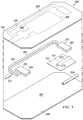
- the apparatus 206may be used as the apparatus 106 in the system 100 of FIGURE 1 .
- the apparatus 206comprises a plurality of sheets, including a first sheet 246, a second sheet 249, and a third sheet 252, as well as a foam member 255.
- the first sheet 246, the second sheet 249, the third sheet 252, and the foam member 255may be combined (by coupling a portion, enclosing, or other techniques) with one another to form the various components of the apparatus 206, including the first valve 218, the second valve 227, the reservoir 224, and the reduced-pressure conduit 221.
- the first valve 218, the second valve 227, the reservoir 224, and the reduced-pressure conduit 221are functionally analogous to the first valve 118, the second valve 127, the reservoir 124, and the reduced-pressure conduit 121 in FIGURE 1 , respectively.
- the first sheet 246, the second sheet 249, and the third sheet 252may be composed of any liquid impermeable material.
- the material from which the first sheet 246, the second sheet 249, and the third sheet 252 may be formedinclude polyvinyl chloride (PVC), polyurethane (PU), polyolefins, polyethylene (PE), polypropylene (PP), etc.
- the first sheet 246, the second sheet 249, and the third sheet 252may formed from a flexible or rigid material.
- each of the first sheet 246, the second sheet 249, and the third sheet 252may be composed of the same material, each of the first sheet 246, the second sheet 249, and the third sheet 252 may also be composed of different materials.
- the third sheet 252may be composed of a different material than the first sheet 246 and the second sheet 249.
- the first sheet 246 and the second sheet 249are approximately the same size and shape.
- the third sheet 252may be smaller than the first sheet 246 or the second sheet 249.
- the first sheet 246, the second sheet 249, the third sheet 252, and the foam member 255may be coupled to one another in a wide variety of ways to form the various components of the apparatus 206.
- the first sheet 246may be coupled to at least one of the second sheet 249 and the third sheet 252 along lines 258 to form the first valve 218, the second valve 227, the reservoir 224, and the reduced-pressure conduit 221.
- the lines 258may form any pattern that provides desirable characteristics for the apparatus 206, including the various components thereof.
- first sheet 246may be coupled to at least one of the second sheet 249 and the third sheet 252 at the lines 258 in any manner, including welding (e.g., ultrasonic or RF), bonding, adhesives (e.g., silicone adhesive), cements, etc.
- weldinge.g., ultrasonic or RF
- bondinge.g., adhesives (e.g., silicone adhesive), cements, etc.
- the first sheet 246may be coupled to at least one of the second sheet 249 and the third sheet 252 to form the reservoir 224 and the reduced-pressure conduit 221.
- the first sheet 246may be coupled to the second sheet 249 and the third sheet 252 along a portion 261 of the lines 258 to form the reservoir 224.
- the reservoir 224may be at least partially formed by abutting portions of the first sheet 246 and the second sheet 249 and abutting portions of the first sheet 246 and the third sheet 252. "Abutting" may mean next to each other or near and yet spaced.
- first sheet 246may be coupled to the second sheet 249 and the third sheet 252 along a portion 264 of the lines 258 to form the reduced-pressure conduit 221.
- the reduced-pressure conduit 221may be at least partially formed by abutting portions of the first sheet 246 and the second sheet 249 and abutting portions of the first sheet 246 and the third sheet 252.
- the third sheet 252may also be coupled to the second sheet 249 along lines 271 to form an inlet conduit 273.
- the inlet conduit 273may be at least partially formed by abutting portions of the third sheet 252 and the second sheet 249.
- the inlet conduit 273may transfer the liquid 250 to the reservoir 224.
- the inlet conduit 273may also include an aperture or hole 275, and the liquid 250 may be transferred from the inlet conduit 273 to the reservoir 224 via the hole 275.
- the apparatus 206also includes a first delivery conduit 234, which delivers the liquid 250 from a liquid source to the inlet conduit 273.
- the first delivery conduit 234is insertable into the inlet conduit 273, and may be removably coupled to the inlet conduit 273 by any technique, including interference fit.
- the apparatus 206also includes the foam member 255, which may be disposed between the first sheet 246 and the second sheet 249 and at least partially enclosed therebetween. In addition or alternatively, a portion 267 of the foam member 255 may also be disposed between the first sheet 246 and the third sheet 252.
- the foam member 255is operable to transfer reduced pressure, which may be from a reduced-pressure source, and the liquid 250, which may be from a liquid source.
- a portion 269 of the foam member 255may be included between the portions of the first sheet 246 and the second sheet 249 that form the reduced-pressure conduit 221, as well as between the portions of the first sheet 246 and the third sheet 252 that form the reduced-pressure conduit 221.
- the portion 269 of the foam member 255may thus transfer reduced pressure through the reduced-pressure conduit 221.
- a portion of the foam member 255may also be used to help form the reservoir 224.
- the foam member 255is composed of foam
- the foam member 255may be composed of any material that is capable of transferring reduced pressure or the liquid 250.
- the foam member 255may be any manifold material.
- the foam member 255may also be composed of compressible materials.
- a first end 277 of the foam member 255forms at least a portion of the first valve 218.
- the first end 277 of the foam member 255may be an enlarged end portion, and may have any shape, including a rectangular, circular, diamond, elliptical, or polygonal shape.
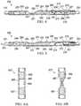
- the first end 277compresses in the presence of reduced pressure to a compressed state 279, as shown in FIGURE 4 .
- the first end 277may expand back to an original size in an absence of reduced pressure to form an expanded state 281, as shown in FIGURE 5 .
- the first valve 218is in an open position.
- the first valve 218When the first end 277 is in the expanded state 281, the first valve 218 is in a closed position. Thus, when the reduced-pressure conduit 221 transfers reduced pressure to the first end 277, which forms part of the first valve 218, the first end 277 compresses to create a space 283 through which the liquid 250 may flow. In particular, the liquid 250 may flow from the first delivery conduit 234 and into the reservoir 224 via the hole 275, as indicated by arrows 284. Conversely, when reduced pressure is absent at the first end 277, the first end 277 is in the expanded state 281 to reduce or eliminate the space 283, and the liquid 250 is obstructed from flowing from the first delivery conduit 234 into the reservoir 224.
- the apparatus 206also includes the second valve 227, which may be at least partially formed by a first wall 285 and the second wall 287.
- the first wall 285may be a portion of the first sheet 246, and the second wall 287 may be a portion of the second sheet 249.
- the first wall 285 and the second wall 287are drawn nearer to one another in the presence of reduced pressure to form a closed position, as shown in FIGURE 4 .
- the first wall 285 and the second wall 287may firmly abut one another to form the closed position.
- the first wall 285 and the second wall 287may also move away from one another in an absence of reduced pressure to form an open position, as shown in FIGURE 5 .
- a space 289exists between the first wall 285 and the second wall 287 to allow the liquid 250 in the reservoir 224 to flow out of the reservoir 224 and into the second delivery conduit 231, as indicated by arrows 291.
- the second delivery conduit 231may then deliver the liquid 250 to a tissue site.
- the liquid 250may pass through a second end 292 of the foam member 255.
- the movement of the first wall 285 away from the second wall 287 in the absence of reduced pressuremay be assisted by the second end 292 of the foam member 255.
- the second end 292 of the foam member 255may be an enlarged end portion 293.
- the second end 292 of the foam member 255may bias the first wall 285 away from the second wall 287.
- the second end 292 of the foam member 255assists in opening the second valve 227 in the absence of reduced pressure at the second valve 227.
- the apparatus 206may also include a set of restriction strips, e.g., 294, 295, and 296.
- the set of restriction stripsmay include one or more restriction strips.
- the set of restriction strips 294, 295, and 296are disposed over at least a portion of the reservoir 224.
- the set of restriction strips 294, 295, and 296are operable to restrict expansion of the reservoir 224 to contain a maximum amount of the liquid 250.
- Each of the set of restriction strips 294, 295, and 296is removable from the reservoir 224 to increase the maximum amount of the liquid 250 that may be held by the reservoir 224.
- the reservoir 224may be able to hold 10 milliliters of the liquid 250 when restriction strips 294, 295, and 296 are applied to the reservoir 224.
- Restriction strip 294may be removed from the reservoir 224 to increase the maximum amount of the liquid 250 that is holdable by the reservoir 224 to 15 milliliters. Restriction strip 295 may be removed from the reservoir 224 to increase the maximum amount of the liquid 250 that is holdable by the reservoir 224 to 20 milliliters. In addition, all of the restriction strips 294, 295, and 296 may be removed from the reservoir 224, in which case the reservoir 224 may be allowed to expand to a maximum capacity. While specific illustrative examples are provided, i.e., 10 milliliters, 15 milliliters, and 20 milliliters, it should be understood that any volume may be used for the reservoir 224 and the volume provided with restriction strips 294, 295, 296.
- the apparatus 206may include a column (not shown) that is slidably coupled to the reservoir 224.
- the columnmay be slidable into a plurality of positions, and may be slidable along the length, width, or thickness of the reservoir 224. The position of the column determines a maximum amount of the liquid 250 that may be held by the reservoir 224.
- the reservoir 224may be a syringe that has a valve on each end. The syringe may also include an internal slidable column.
- reduced pressuremay be applied to the apparatus 206 to change the positions of the first valve 218 and the second valve 227, and thereby manage the flow of the liquid 250 to a tissue site.
- reduced pressureis transmitted from a reduced-pressure source, such as the reduced-pressure source 115 in FIGURE 1 , to the first valve 218 and the second valve 227 via the reduced-pressure conduit 221.
- the reduced pressuremay be transmitted from the reduced-pressure source 115 via a tissue site.
- the first valve 218has an open position in the presence of reduced pressure at the first valve 218, and the second valve 227 has a closed position in the presence of reduced pressure at the second valve 227.
- the reservoir 224receives the liquid 250 from a liquid source, and the second valve 227 obstructs the liquid 250 from flowing out of the reservoir 224.
- the set of restriction strips 294, 295, and 296may restrain the expansion of the reservoir 224 such that the reservoir 224 is able to hold a predetermined maximum amount of the liquid 250. In one example, this predetermined maximum amount may be a prescribed dosage.
- FIGURE 5Little or no reduced pressure is transferred from a reduced-pressure source to the first valve 218 and the second valve 227 via the reduced-pressure conduit 221.
- the first valve 218has a closed position to obstruct the flow of the liquid 250 into the reservoir 224
- the second valve 227has an open position to allow the liquid 250 to flow from the reservoir 224 to a tissue site.
- the valves 218 and 227could be structured to open and close opposite to that described.
- a second valve 627which may be used as the second valve 227 in FIGURE 2 , is shown according to an illustrative embodiment.
- the second valve 627is shown in an open position.
- the second valve 627is shown in a closed position.
- the second valve 627includes spacers 697 and 698. In an absence of reduced pressure at the second valve 627, the spacers 697 and 698 bias the first wall 685 away from the second wall 687 to form the space 689.
- the spacers 697 and 698may be composed of any elastic resilient material that is either formed with apertures or is liquid permeable.
- FIGURE 7a schematic graph 700 illustrating the level of reduced pressure over time in an apparatus, such as apparatus 106 in FIGURE 1 or apparatus 206 in FIGURE 2 , for managing liquid flow associated with a tissue site is depicted in accordance with an illustrative embodiment.
- reduced pressureis applied to the apparatus for managing liquid flow.
- the reduced pressuremay be supplied by a tissue site, which, in turn, receives reduced pressure from a separate reduced-pressure device or source, e.g., the reduced-pressure source 115 in FIGURE 1 , which may include a controller.
- the separate reduced-pressure deviceis turned on during time period 704.
- the reduced pressureis transferred to a first valve and a second valve, such as a first valve and a second valve described in any of the illustrative embodiments.
- the first valveis in an open position and the second valve is in a closed position such that a reservoir, as described in any of the illustrative embodiments, fills with a liquid from a liquid source up to a predetermined or maximum volume. The liquid, however, is obstructed from exiting the reservoir and flowing to a tissue site during the time period 704.
- the separate reduced-pressure source that supplies reduced pressure to the tissue sitemay be turned off, or may supply a relatively lesser amount of reduced pressure than during the time period 704.
- the absence of reduced pressure at the first valve and the second valvecauses the first valve to have a closed position and the second valve to have an open position.
- the volume of liquid in the reservoiris allowed to exit the reservoir and flow to a tissue site.
- the reduced pressuremay be oscillated between the reduced pressure in the time period 704 and the reduced pressure in the time period 705 so that the flow of liquid to a tissue site may be managed in measured doses.
- the reduced pressure supplied by the separate reduced-pressure source to the tissue sitemay be turned off and on in predetermined time internals, such as the time period 704 and the time period 705.
Landscapes
- Health & Medical Sciences (AREA)
- Heart & Thoracic Surgery (AREA)
- Animal Behavior & Ethology (AREA)
- General Health & Medical Sciences (AREA)
- Anesthesiology (AREA)
- Biomedical Technology (AREA)
- Hematology (AREA)
- Life Sciences & Earth Sciences (AREA)
- Veterinary Medicine (AREA)
- Engineering & Computer Science (AREA)
- Public Health (AREA)
- Vascular Medicine (AREA)
- Pulmonology (AREA)
- Otolaryngology (AREA)
- External Artificial Organs (AREA)
- Media Introduction/Drainage Providing Device (AREA)
- Surgical Instruments (AREA)
- Infusion, Injection, And Reservoir Apparatuses (AREA)
Description
- Clinical studies and practice have shown that providing a reduced pressure in proximity to a tissue site augments and accelerates the growth of new tissue at the tissue site. The applications of this phenomenon are numerous, but application of reduced pressure has been particularly successful in treating wounds. This treatment (frequently referred to in the medical community as "negative pressure wound therapy," "reduced pressure therapy," or "vacuum therapy") provides a number of benefits, including faster healing, and increased formulation of granulation tissue.
- The invention is defined by the apparatus of claim 1. There is provided an apparatus for managing liquid flow associated with a tissue site, the apparatus comprising: a first valve in fluid communication with a reduced-pressure source, the first valve movable between an open position and a closed position, wherein the first valve is operable to be activated based on a presence of reduced pressure; a second valve in fluid communication with the reduced-pressure source, the second valve movable between an open position and a closed position, wherein the second valve is operable to be activated based on the presence of reduced pressure; wherein at least one of the first valve and the second valve is in the closed position to obstruct a flow of a liquid when experiencing reduced pressure; a reservoir fluidly coupled to the first valve and the second valve, the reservoir operable to contain a liquid when the second valve is in the closed position; and a reduced-pressure conduit in fluid communication with the first valve and the second valve, wherein the reduced-pressure conduit is operable to transmit reduced pressure from the tissue site to the first valve and the second valve; wherein the first valve moves from the closed position to the open position in the presence of reduced pressure at the first valve; wherein the first valve moves from the open position to the closed position in an absence of reduced pressure at the first valve; wherein the second valve moves from the open position to the closed position in the presence of reduced pressure at the second valve; and wherein the second valve moves from the closed position to the open position in an absence of reduced pressure at the second valve.
A selection of optional features is set out in the dependent claims.US 4,935,005 discloses a fluid control apparatus for an ultrasonic surgical tool, including a valve system to remove the source of suction and controllably admit irrigation fluid.US 5, 261,883 disclose a system for controlling the amount of fluid flowing to and from a surgical site. - According to another illustrative, non-limiting embodiment, a method for managing liquid flow associated with a tissue site includes providing a valve arrangement having a first valve, a second valve, and a reservoir, and receiving reduced pressure at the first valve and the second valve. The first valve and second valve each have an open position and a closed position. The method further includes changing a flow status (open to closed or vice versa) of the first valve in response to receiving reduced pressure at the first valve, receiving a liquid at the reservoir when the first valve is open, changing a flow status of the second valve in response to receiving reduced pressure at the second valve, and obstructing a flow of liquid from the reservoir when the second valve is closed.
- According to another illustrative, non-limiting embodiment, a method for managing liquid flow associated with a tissue site includes providing a valve arrangement with a first valve, a second valve, and a reservoir. The method also includes fluidly coupling the first valve to a liquid source, fluidly coupling the second valve to the tissue site, changing a position of the first valve to one of an open position and a closed position based on a presence of reduced pressure at the first valve, and changing a position of the second valve to the other of the open position and the closed position based on a presence of reduced pressure at the second valve.
- According to another illustrative, non-limiting embodiment, a method of manufacturing an apparatus for managing liquid flow associated with a tissue site includes providing a first valve moveable between an open position and a closed position and operable to change flow status based on a presence of reduced pressure, providing a second valve moveable between an open position and a closed position and operable to change flow status based on the presence of reduced pressure, and providing a reservoir operable to contain a liquid. The method further includes coupling the reservoir to the first valve and the second valve such that the reservoir is disposed between the first valve and the second valve.
- According to another illustrative, non-limiting embodiment, a method of manufacturing an apparatus for managing liquid flow associated with a tissue site includes providing a first sheet, providing a second sheet, providing a foam member, and coupling the first sheet to the second sheet to form a reduced-pressure conduit, a reservoir, a first valve, and a second valve. The foam member is enclosed between the first sheet and the second sheet.
- Other features and advantages of the illustrative, non-limiting embodiments will become apparent with reference to the drawings and detailed description that follow.
- A more complete understanding may be obtained by reference to the following Detailed Description when taken in conjunction with the accompanying Drawings, wherein like numerals indicate like elements throughout, and wherein:
FIGURE 1 is a schematic diagram of a treatment system for managing liquid flow associated with a tissue site in accordance with an illustrative embodiment;FIGURE 2 is a schematic, perspective view of an apparatus for managing liquid flow associated with a tissue site in accordance with an illustrative embodiment;FIGURE 3 is a schematic, exploded perspective view of an apparatus for managing liquid flow associated with a tissue site in accordance with an illustrative embodiment;FIGURE 4 is a schematic cross-sectional view of the apparatus ofFIGURE 2 taken along line 4-4 when at least a portion of the apparatus is exposed to reduced pressure;FIGURE 5 is a schematic cross-sectional view of the apparatus ofFIGURE 2 taken along line 4-4 when reduced pressure is absent from the apparatus;FIGURE 6A is a schematic cross-sectional view of a valve in an open position in accordance with an illustrative embodiment;FIGURE 6B is a schematic cross-sectional view of a valve in a closed position in accordance with an illustrative embodiment; andFIGURE 7 is a schematic graph illustrating the level of reduced pressure over time in an apparatus for managing liquid flow associated with a tissue site in accordance with an illustrative embodiment.- In the following detailed description of the illustrative embodiments, reference is made to the accompanying drawings that form a part hereof. These embodiments are described in sufficient detail to enable those skilled in the art to practice the invention, and it is understood that other embodiments may be utilized and that logical structural, mechanical, electrical, and chemical changes may be made without departing from the spirit or scope of the invention. To avoid detail not necessary to enable those skilled in the art to practice the embodiments described herein, the description may omit certain information known to those skilled in the art. The following detailed description is, therefore, not to be taken in a limiting sense, and the scope of the illustrative embodiments are defined only by the appended claims.
- Referring primarily to
FIGURE 1 , asystem 100 for managing liquid flow associated with atissue site 103 is shown according to an illustrative embodiment. Anapparatus 106, or valve arrangement, which is included in thesystem 100, manages the flow of liquid from aliquid source 109 to thetissue site 103. Theapparatus 106 may control the amount of liquid that flows to thetissue site 103, including whether the liquid flows to thetissue site 103 at all. Theapparatus 106 uses reduced pressure from a reduced-pressure source 115 to help manage liquid flow from theliquid source 109 to thetissue site 103. - As used herein, "reduced pressure" generally refers to a pressure less than the ambient pressure at a tissue site that is being subjected to treatment. In most cases, this reduced pressure will be less than the atmospheric pressure at which the patient is located. Alternatively, the reduced pressure may be less than a hydrostatic pressure at the tissue site. Unless otherwise indicated, values of pressure stated herein are gauge pressures. The reduced pressure delivered may be constant or varied (patterned or random) and may be delivered continuously or intermittently. Although the terms "vacuum" and "negative pressure" may be used to describe the pressure applied to the tissue site, the actual pressure applied to the tissue site may be more than the pressure normally associated with a complete vacuum. Consistent with the use herein, an increase in reduced pressure or vacuum pressure typically refers to a relative reduction in absolute pressure. Unless otherwise indicated, as used herein, "or" does not require mutual exclusivity.
- The reduced-
pressure source 115 supplies reduced pressure to theapparatus 106 via thetissue site 103. The reduced pressure may be supplied from the reduced-pressure source 115 to thetissue site 103 through aconduit 116. Residual reduced pressure may continue to be supplied by at least aportion 112 of thetissue site 103 to theapparatus 106 even when the reduced-pressure source 115 is turned off-at least until the reduced pressure in the tissue site is disseminated. The reduced-pressure source 115 may be any device or system that generates or provides a reduced pressure, including, but not limited to, manually operated or powered pumps or wall suction. As non-limiting examples, the reduced-pressure source 115 may include devices that are manually actuated, battery operated, or any form of pneumatic pump. In one example, the pump uses low amounts of power and is capable of operating for an extended period of time on a single charge of the battery. As another non-limiting example, the reduced-pressure source 115 may be wall suction. As shown by the non-limiting examples, the possibilities for the reduced-pressure source 115 are numerous. - The
liquid source 109 supplies liquid to thetissue site 103 via theapparatus 106. Theliquid source 109 may be any container, bag, or other device capable of holding a liquid. The liquid supplied by theliquid source 109 may be any liquid, including liquids that contain solid particles. In one example, the liquid supplied by theliquid source 109 may facilitate the healing or growth of thetissue site 103. The liquid supplied by theliquid source 109 may contain growth factors, healing factors, antibiotics, medicines, etc. - The
tissue site 103 may be the bodily tissue of any human, animal, or other organism, including adipose tissue, muscle tissue, dermal tissue, vascular tissue, connective tissue, cartilage, tendons, ligaments, bone, or any other tissue. While thetissue site 103 may include a wound (including an open wound or an incision), diseased tissue, or defective tissue, thetissue site 103 may also be healthy tissue that is not wounded, diseased, or defective. The application of reduced pressure to thetissue site 103 may be used to promote the drainage of exudate and other liquids from thetissue site 103, as well as stimulate the growth of additional tissue. In the case in which thetissue site 103 is a wound site, the growth of granulation tissue and removal of exudates and bacteria promotes healing of the wound. The application of reduced pressure to non-wounded or non-defective tissue, including healthy tissue, may be used to promote the growth of tissue that may be harvested and transplanted to another tissue location. The delivery of liquid from theliquid source 109 to thetissue site 103 via theapparatus 106 may be used in conjunction with the application of reduced pressure to thetissue site 103 to facilitate the healing, growth, or other treatment of thetissue site 103. - The
apparatus 106 for managing liquid flow to thetissue site 103 includes afirst valve 118 in fluid communication with the reduced-pressure source 115. In one example, fluid communication between thefirst valve 118 and the reduced-pressure source 115 may be provided, at least in part, by an intermediate reduced-pressure conduit, or reduced-pressure conduit 121. Thefirst valve 118 is movable between an open position and a closed position. In an open position, thefirst valve 118 may be partially or fully open, and liquid from theliquid source 109 is allowed to pass through thefirst valve 118 and into areservoir 124 that is operable to contain the liquid. In a closed position, thefirst valve 118 may be partially or fully closed, and thefirst valve 118 obstructs or prevents the flow of liquid from theliquid source 109 into thereservoir 124. - The
first valve 118 is activated, or changes flow status, i.e., moves from the open position to the closed position or vice versa, based on a presence or absence of reduced pressure at thefirst valve 118. The reduced pressure may be transferred to thefirst valve 118 from the reduced-pressure source 115 to thefirst valve 118 at least in part by the reduced-pressure conduit 121. In one example, thefirst valve 118 moves from a closed position to an open position in the presence of reduced pressure at thefirst valve 118, and thefirst valve 118 moves from an open position to a closed position in an absence of reduced pressure at thefirst valve 118. As used herein, an "absence" of reduced pressure may include a partial or total absence of reduced pressure. - The
apparatus 106 also includes asecond valve 127 in fluid communication with the reduced-pressure source 115. In one example, fluid communication between thesecond valve 127 and the reduced-pressure source 115 may be at least partially provided by the reduced-pressure conduit 121. In the example in which the reduced-pressure conduit 121 provides fluid communication between thesecond valve 127 and the reduced-pressure source 115, the reduced-pressure conduit 121 may be an air-permeable material, a portion of which extends into asecond delivery conduit 131. Thesecond valve 127 is activated, or changes flow status, i.e., moves from an open position to a closed position or vice versa, based on the presence or absence of reduced pressure. In an open position, thesecond valve 127 may be partially or fully open, and liquid from thereservoir 124 is allowed to pass through thesecond valve 127, into thesecond delivery conduit 131, and to thetissue site 103. In the closed position, thesecond valve 127 may be partially or fully closed, and thesecond valve 127 obstructs or prevents the flow of liquid to the into thesecond delivery conduit 131 and thus to thetissue site 103. - In one example, the
second valve 127 moves between the open position or the closed position based on a presence of reduced pressure at thesecond valve 127. In this example, the reduced pressure may be transferred to thesecond valve 127 from the reduced-pressure source 115, at least in part, by the reduced-pressure conduit 121 and thesecond delivery conduit 131. In one example, thesecond valve 127 moves from an open position to a closed position in the presence of reduced pressure at thesecond valve 127, and thesecond valve 127 moves from a closed position to an open position in an absence of reduced pressure at thesecond valve 127. - Numerous valve types may be used for the
first valve 118 and thesecond valve 127. In one embodiment, thefirst valve 118 and thesecond valve 127 are pilot-actuated valves. In one example of this embodiment, thefirst valve 118 and thesecond valve 127 may include a master and slave cylinder, and may be made from machined brass. In another embodiment, thefirst valve 118 and thesecond valve 127 may be diaphragm valves. - In one embodiment, the
reservoir 124 is operable to contain a liquid and transport the liquid from thefirst valve 118 to thesecond valve 127. Thereservoir 124 may be disposed between thefirst valve 118 and thesecond valve 127. In one non-limiting example, afirst end 125 of thereservoir 124 is coupled to thefirst valve 118, and asecond end 126, which is opposite thefirst end 125, of thereservoir 124 is coupled to thesecond valve 127. As used herein, the term "coupled" includes coupling via a separate object, and also includes direct coupling. In the case of direct coupling, the two coupled objects touch each other in some way. The term "coupled" also encompasses two or more components that are continuous with one another by virtue of each of the components being formed from the same piece of material. Also, the term "coupled" includes chemical coupling, such as via a chemical bond. The term "coupled" may also include mechanical, thermal, or electrical coupling. The term "coupled" may also include fluidly coupled, in which case a first object that is coupled to a second object is in fluid communication with that second object. - As shown in the illustrative embodiments disclosed herein, the volumetric capacity of the
reservoir 124 may be varied. For example, the size of thereservoir 124 may be increased or decreased to vary the volumetric capacity of thereservoir 124. In one non-limiting example, thereservoir 124 may have a volumetric capacity that corresponds to a predetermined medicinal dosage such that the predetermine dosage of medicinal liquid is delivered to thetissue site 103 when thesecond valve 127 moves to an open position. - In one illustrative embodiment, the
reservoir 124 may be flexible, in which case the volume of thereservoir 124 may vary depending on the amount of liquid in thereservoir 124. The flexibility of thereservoir 124 may facilitate the movement of liquid out of thereservoir 124. In another illustrative embodiment, thereservoir 124 may be a rigid container. Thereservoir 124 may also include a vent line (not shown) that permits the entry of a gas, such as air, into thereservoir 124. The vent line may facilitate the movement of liquid out of thereservoir 124 and toward thetissue site 103. The vent line may be associated with theliquid source 109 or afirst delivery conduit 134. Additional illustrative, non-limiting embodiments suitable for use as thereservoir 124 are provided below inFIGURES 2-5 . - In one illustrative, non-limiting embodiment, the
valves TABLE 1. Pressure Status At Tissue Site First Valve 118 Second Valve 127Reduced Pressure Present Open Closed Reduced Pressure Not Present Closed Open - The position of the valves could be readily changed to be the opposite of what is shown in TABLE 1 for the different pressure statuses as shown in TABLE 2.
TABLE 2. Pressure Status At Tissue Site First Valve 118 Second Valve 127Reduced Pressure Present Closed Open Reduced Pressure Not Present Open Closed - At least one of the
first valve 118 and thesecond valve 127 is in a closed position to obstruct or prevent the flow of the liquid. In the illustrative, non-limiting example represented in TABLE 1, thefirst valve 118 has one of an open position or a closed position and thesecond valve 127 has the other of the open position or the closed position such that thefirst valve 118 and thesecond valve 127 each have different positions. When reduced pressure is present at thetissue site 103, the reduced pressure may be transferred to thefirst valve 118 and thesecond valve 127 byconduits first valve 118 to have an open position and thesecond valve 127 to have a closed position. When thefirst valve 118 is in an open position and thesecond valve 127 is in a closed position, liquid is allowed to move from theliquid source 109 to thereservoir 124, but thesecond valve 127 obstructs or prevents the liquid from moving intoconduits tissue site 103. Thereservoir 124 may then be allowed to fill to a predetermined volume, such as a predetermined medicinal dosage. - The absence of reduced pressure at the
tissue site 103 may cause thefirst valve 118 to have a closed position and thesecond valve 127 to have an open position. When thefirst valve 118 has a closed position and thesecond valve 127 has an open position, liquid is allowed to move from thereservoir 124 to thetissue site 103, but thefirst valve 118 obstructs or prevents the liquid from moving to thereservoir 124 from theliquid source 109. Thus, the predetermined volume of liquid in thereservoir 124 is delivered to thetissue site 103 while thefirst valve 118 helps to prevent additional liquid from being added to the predetermined volume of liquid delivered from thereservoir 124. - In one embodiment, the
system 100 includes thefirst delivery conduit 134 that is in fluid communication with thefirst valve 118, and when thefirst valve 118 is open, withreservoir 124. Thefirst delivery conduit 134 is operable to deliver the liquid from theliquid source 109 to theapparatus 106. Thefirst delivery conduit 134 may deliver liquid from theliquid source 109 to thereservoir 124 when thefirst valve 118 is in an open position. - In one embodiment, the
system 100 includes thesecond delivery conduit 131 that is in fluid communication with thereservoir 124 when thesecond valve 127 is in the open position. Thesecond delivery conduit 131 is operable to deliver liquid from theapparatus 106 to thetissue site 103. For example, liquid may be delivered from thereservoir 124 to thetissue site 103 via thesecond delivery conduit 131. In this example, thesecond delivery conduit 131 may deliver liquid from thereservoir 124 to thetissue site 103 when thesecond valve 127 is in the open position. - In one illustrative embodiment, the reduced-
pressure conduit 121 fluidly couples thefirst valve 118 and thesecond delivery conduit 131. In addition, the reduced-pressure conduit 121 may fluidly couple thefirst valve 118 and thesecond valve 127. In the illustrative embodiment ofFIGURE 1 , reduced pressure is delivered through thesecond delivery conduit 131 to the reduced-pressure conduit 121, which delivers the reduced pressure to thefirst valve 118 and thesecond valve 127. - In one non-limiting example, reduced pressure from the
tissue site 103 is transferred to the reduced-pressure conduit 121 by thesecond delivery conduit 131. The reduced-pressure conduit 121 has afirst portion 140 and asecond portion 137. Thefirst portion 140 of the reduced-pressure conduit 121 transfers reduced pressure from thesecond delivery conduit 131 to thefirst valve 118. Thesecond portion 137 of the reduced-pressure conduit 121 transfers reduced pressure from thesecond delivery conduit 131 to thesecond valve 127. - In another non-limiting example, the
second delivery conduit 131 may directly deliver reduced pressure from thetissue site 103 to thesecond valve 127 without the intervening reduced-pressure conduit 121 (or alternatively, thesecond portion 137 may comprise a portion of the second delivery conduit 131). In this non-limiting example, the reduced-pressure conduit 121 may be in fluid communication with thefirst valve 118, and may be operable to transmit reduced pressure directly from thetissue site 103 to thefirst valve 118. Also, in this non-limiting example, the reduced-pressure conduit 121 may be fluidly coupled to thesecond delivery conduit 131 or thetissue site 103. - The
system 100 may also include a manifold 143 that may be placed adjacent or in contact with thetissue site 103. The manifold 143 may distribute the liquid received from theapparatus 106 to thetissue site 103. The manifold 143 may be a biocompatible, porous material that is capable of being placed in contact with thetissue site 103 and distributing reduced pressure or liquid to thetissue site 103. The manifold 143 may be made from foam, gauze, felted mat, or other suitable material or structure that distributes reduced pressure. The manifold 143 may include a plurality of flow channels or pathways to facilitate distribution of reduced pressure or liquid to or from tissue site 101. - The manifold 143 may further serve as a scaffold for new cell-growth, or a scaffold material may be used in conjunction with the manifold 143 to promote cell-growth. A scaffold is a substance or structure used to enhance or promote the growth of cells or formation of tissue, such as a three-dimensional porous structure that provides a template for cell growth. Illustrative examples of scaffold materials include calcium phosphate, collagen, PLA/PGA, coral hydroxy apatites, carbonates, or processed allograft materials. In one example, the scaffold material has a high void-fraction (i.e. a high content of air). In another embodiment, the
system 100 does not include themanifold 143. - By using reduced pressure from the reduced-
pressure source 115, thesystem 100 is able to effectively manage the flow of liquid from theliquid source 109 to thetissue site 103. Measured dosages of liquid, such as a medicinal liquid, may be released from thereservoir 124 to thetissue site 103 at predetermined time intervals. For example, reduced pressure from the reduced-pressure source 115 may be applied to thetissue site 103 in a cyclic manner to determine when liquid is released from thereservoir 124 to thetissue site 103. In this example, when the reduced-pressure source 115 applies reduced pressure to thetissue site 103, the reduced pressure is transferred to thefirst valve 118 and thesecond valve 127 to cause thefirst valve 118 to have an open position and thesecond valve 127 to have a closed position. Thus, liquid is allowed to flow from theliquid source 109 to thereservoir 124, but is obstructed from flowing from thereservoir 124 to thetissue site 103. When the reduced-pressure source 115 ceases to apply reduced pressure to thetissue site 103, thereby causing an absence of reduced pressure at thetissue site 103, thefirst valve 118 may transition to a closed position and thesecond valve 127 transition to an open position. Thus, a measured dosage of liquid in thereservoir 124 is allowed to flow to thetissue site 103, and thefirst valve 118 obstructs liquid from flowing into thereservoir 124 from theliquid source 109. In this manner, the reduced pressure applied to thetissue site 103 by the reduced-pressure source 115 may be cycled to manage the application of liquid to thetissue site 103. - In one embodiment, a method for managing liquid flow associated with the
tissue site 103 may include receiving reduced pressure at thefirst valve 118 and thesecond valve 127. The reduced pressure may be received by thefirst valve 118 and thesecond valve 127 via the reduced-pressure conduit 121 or thesecond delivery conduit 131. The method may also include opening thefirst valve 118 in response to receiving reduced pressure at thefirst valve 118. The method may also include receiving a liquid at thereservoir 124 in response to opening thefirst valve 118. The method may also include closing thesecond valve 127 in response to receiving reduced pressure at thesecond valve 127. The method may also include obstructing a flow of liquid from thereservoir 124 in response to closing thesecond valve 127. "Obstructing" includes partially or fully obstructing. - In one embodiment, the method may also include closing the
first valve 118 in response to an absence of reduced pressure at thefirst valve 118. The reduced-pressure source 115 may cease to supply reduced pressure to thetissue site 103 and thus cause an absence of reduced pressure at thefirst valve 118. The method may also include obstructing the flow of liquid from theliquid source 109 to thereservoir 124 in response to closing thefirst valve 118. Thesecond valve 127 may open in response to the absence of reduced pressure at thesecond valve 127. Thetissue site 103 may then receive liquid from thereservoir 124 in response to opening thesecond valve 127. - In another embodiment, a method for managing liquid flow associated with the
tissue site 103 may include changing a position of thefirst valve 118 to one of an open position or a closed position based on the presence of reduced pressure at thefirst valve 118. The method also includes changing a position of thesecond valve 127 to the other of the open position or the closed position. The method may also include obstructing a flow of liquid using the valve having the closed position, which, in this embodiment, may be either thefirst valve 118 or thesecond valve 127. - In one example, changing the position of the
first valve 118 to one of the open position or the closed position based on the presence of reduced pressure at thefirst valve 118 includes changing the position of thefirst valve 118 from the closed position to the open position in the presence of reduced pressure. In another example, changing the position of thefirst valve 118 to one of the open position or the closed position based on the presence of reduced pressure at thefirst valve 118 includes changing the position of thefirst valve 118 from the open position to the closed position in an absence of reduced pressure. In another example, thefirst valve 118 is in the closed position, and obstructing the flow of liquid using the valve having the closed position includes obstructing the liquid from being received by thereservoir 124 using thefirst valve 118. In another example, the method may include receiving liquid at thereservoir 124 when thefirst valve 118 is in the open position. - In one example, changing the position of the
second valve 127 to the other of the open position or the closed position includes changing the position of thesecond valve 127 from the open position to the closed position in the presence of reduced pressure. In another example, thesecond valve 127 is in the closed position, and obstructing the flow of liquid using the valve having the closed position includes obstructing the liquid from leaving thereservoir 124 using thesecond valve 127. In another example, changing the position of thesecond valve 127 to the other of the open position or the closed position includes changing the position of thesecond valve 127 from the closed position to the open position in an absence of reduced pressure. In another example, the method may include receiving liquid at thetissue site 103 when thesecond valve 127 is in the open position. - In one embodiment, a method of manufacturing an apparatus for managing liquid flow associated with the
tissue site 103 includes providing thefirst valve 118, which is capable of having an open position and a closed position based on a presence of reduced pressure. The method also includes providing thesecond valve 127, which is capable of having an open position or a closed position based on the presence of reduced pressure. The method may also include providing thereservoir 124, which is operable to contain a liquid, and fluidly coupling thereservoir 124 to thefirst valve 118 and thesecond valve 127. Thereservoir 124 may be disposed between thefirst valve 118 and thesecond valve 127. - In one example, the method of manufacturing also includes providing the reduced-
pressure conduit 121, and coupling the reduced-pressure conduit 121 to at least one of thefirst valve 118 and thesecond valve 127. In this example, the reduced-pressure conduit 121 is operable to transfer reduced pressure to at least one of thefirst valve 118 and thesecond valve 127. - Referring now primarily to
FIGURES 2-5 , anapparatus 206, or valve arrangement, is shown according to an illustrative embodiment. Theapparatus 206 may be used as theapparatus 106 in thesystem 100 ofFIGURE 1 . Theapparatus 206 comprises a plurality of sheets, including afirst sheet 246, asecond sheet 249, and athird sheet 252, as well as afoam member 255. In one embodiment, thefirst sheet 246, thesecond sheet 249, thethird sheet 252, and thefoam member 255 may be combined (by coupling a portion, enclosing, or other techniques) with one another to form the various components of theapparatus 206, including thefirst valve 218, thesecond valve 227, thereservoir 224, and the reduced-pressure conduit 221. Thefirst valve 218, thesecond valve 227, thereservoir 224, and the reduced-pressure conduit 221 are functionally analogous to thefirst valve 118, thesecond valve 127, thereservoir 124, and the reduced-pressure conduit 121 inFIGURE 1 , respectively. - The
first sheet 246, thesecond sheet 249, and thethird sheet 252 may be composed of any liquid impermeable material. Non-limiting examples of the material from which thefirst sheet 246, thesecond sheet 249, and thethird sheet 252 may be formed include polyvinyl chloride (PVC), polyurethane (PU), polyolefins, polyethylene (PE), polypropylene (PP), etc. In one example, thefirst sheet 246, thesecond sheet 249, and thethird sheet 252 may formed from a flexible or rigid material. Although each of thefirst sheet 246, thesecond sheet 249, and thethird sheet 252 may be composed of the same material, each of thefirst sheet 246, thesecond sheet 249, and thethird sheet 252 may also be composed of different materials. For example, thethird sheet 252 may be composed of a different material than thefirst sheet 246 and thesecond sheet 249. In one non-limiting example, thefirst sheet 246 and thesecond sheet 249 are approximately the same size and shape. Also, thethird sheet 252 may be smaller than thefirst sheet 246 or thesecond sheet 249. - The
first sheet 246, thesecond sheet 249, thethird sheet 252, and thefoam member 255 may be coupled to one another in a wide variety of ways to form the various components of theapparatus 206. In one embodiment, thefirst sheet 246 may be coupled to at least one of thesecond sheet 249 and thethird sheet 252 alonglines 258 to form thefirst valve 218, thesecond valve 227, thereservoir 224, and the reduced-pressure conduit 221. In addition to the pattern shown inFIGURE 3 , thelines 258 may form any pattern that provides desirable characteristics for theapparatus 206, including the various components thereof. In addition, thefirst sheet 246 may be coupled to at least one of thesecond sheet 249 and thethird sheet 252 at thelines 258 in any manner, including welding (e.g., ultrasonic or RF), bonding, adhesives (e.g., silicone adhesive), cements, etc. - In one example, the
first sheet 246 may be coupled to at least one of thesecond sheet 249 and thethird sheet 252 to form thereservoir 224 and the reduced-pressure conduit 221. In this example, thefirst sheet 246 may be coupled to thesecond sheet 249 and thethird sheet 252 along aportion 261 of thelines 258 to form thereservoir 224. Thus, thereservoir 224 may be at least partially formed by abutting portions of thefirst sheet 246 and thesecond sheet 249 and abutting portions of thefirst sheet 246 and thethird sheet 252. "Abutting" may mean next to each other or near and yet spaced. In addition, thefirst sheet 246 may be coupled to thesecond sheet 249 and thethird sheet 252 along aportion 264 of thelines 258 to form the reduced-pressure conduit 221. Thus, the reduced-pressure conduit 221 may be at least partially formed by abutting portions of thefirst sheet 246 and thesecond sheet 249 and abutting portions of thefirst sheet 246 and thethird sheet 252. - The
third sheet 252 may also be coupled to thesecond sheet 249 alonglines 271 to form aninlet conduit 273. Thus, theinlet conduit 273 may be at least partially formed by abutting portions of thethird sheet 252 and thesecond sheet 249. Theinlet conduit 273 may transfer the liquid 250 to thereservoir 224. Theinlet conduit 273 may also include an aperture orhole 275, and the liquid 250 may be transferred from theinlet conduit 273 to thereservoir 224 via thehole 275. Theapparatus 206 also includes afirst delivery conduit 234, which delivers the liquid 250 from a liquid source to theinlet conduit 273. Thefirst delivery conduit 234 is insertable into theinlet conduit 273, and may be removably coupled to theinlet conduit 273 by any technique, including interference fit. - The
apparatus 206 also includes thefoam member 255, which may be disposed between thefirst sheet 246 and thesecond sheet 249 and at least partially enclosed therebetween. In addition or alternatively, aportion 267 of thefoam member 255 may also be disposed between thefirst sheet 246 and thethird sheet 252. Thefoam member 255 is operable to transfer reduced pressure, which may be from a reduced-pressure source, and the liquid 250, which may be from a liquid source. Aportion 269 of thefoam member 255 may be included between the portions of thefirst sheet 246 and thesecond sheet 249 that form the reduced-pressure conduit 221, as well as between the portions of thefirst sheet 246 and thethird sheet 252 that form the reduced-pressure conduit 221. Theportion 269 of thefoam member 255 may thus transfer reduced pressure through the reduced-pressure conduit 221. In an alternative embodiment, a portion of thefoam member 255 may also be used to help form thereservoir 224. - Although in the examples of
FIGURES 2-5 , thefoam member 255 is composed of foam, thefoam member 255 may be composed of any material that is capable of transferring reduced pressure or the liquid 250. Thefoam member 255 may be any manifold material. Thefoam member 255 may also be composed of compressible materials. - With reference primarily to
FIGURES 3-5 , in one embodiment, afirst end 277 of thefoam member 255 forms at least a portion of thefirst valve 218. Thefirst end 277 of thefoam member 255 may be an enlarged end portion, and may have any shape, including a rectangular, circular, diamond, elliptical, or polygonal shape. In one example, thefirst end 277 compresses in the presence of reduced pressure to acompressed state 279, as shown inFIGURE 4 . Thefirst end 277 may expand back to an original size in an absence of reduced pressure to form an expandedstate 281, as shown inFIGURE 5 . When thefirst end 277 is in thecompressed state 279, thefirst valve 218 is in an open position. When thefirst end 277 is in the expandedstate 281, thefirst valve 218 is in a closed position. Thus, when the reduced-pressure conduit 221 transfers reduced pressure to thefirst end 277, which forms part of thefirst valve 218, thefirst end 277 compresses to create aspace 283 through which the liquid 250 may flow. In particular, the liquid 250 may flow from thefirst delivery conduit 234 and into thereservoir 224 via thehole 275, as indicated byarrows 284. Conversely, when reduced pressure is absent at thefirst end 277, thefirst end 277 is in the expandedstate 281 to reduce or eliminate thespace 283, and the liquid 250 is obstructed from flowing from thefirst delivery conduit 234 into thereservoir 224. - The
apparatus 206 also includes thesecond valve 227, which may be at least partially formed by afirst wall 285 and thesecond wall 287. Thefirst wall 285 may be a portion of thefirst sheet 246, and thesecond wall 287 may be a portion of thesecond sheet 249. In one example, thefirst wall 285 and thesecond wall 287 are drawn nearer to one another in the presence of reduced pressure to form a closed position, as shown inFIGURE 4 . In this example, thefirst wall 285 and thesecond wall 287 may firmly abut one another to form the closed position. Thefirst wall 285 and thesecond wall 287 may also move away from one another in an absence of reduced pressure to form an open position, as shown inFIGURE 5 . In the open position, aspace 289 exists between thefirst wall 285 and thesecond wall 287 to allow the liquid 250 in thereservoir 224 to flow out of thereservoir 224 and into thesecond delivery conduit 231, as indicated byarrows 291. Thesecond delivery conduit 231 may then deliver the liquid 250 to a tissue site. - When the
second valve 227 is in the open position, the liquid 250 may pass through asecond end 292 of thefoam member 255. In addition, the movement of thefirst wall 285 away from thesecond wall 287 in the absence of reduced pressure may be assisted by thesecond end 292 of thefoam member 255. Thesecond end 292 of thefoam member 255 may be anenlarged end portion 293. Thesecond end 292 of thefoam member 255 may bias thefirst wall 285 away from thesecond wall 287. Thus, thesecond end 292 of thefoam member 255 assists in opening thesecond valve 227 in the absence of reduced pressure at thesecond valve 227. - The
apparatus 206 may also include a set of restriction strips, e.g., 294, 295, and 296. The set of restriction strips may include one or more restriction strips. The set of restriction strips 294, 295, and 296 are disposed over at least a portion of thereservoir 224. The set of restriction strips 294, 295, and 296 are operable to restrict expansion of thereservoir 224 to contain a maximum amount of the liquid 250. Each of the set of restriction strips 294, 295, and 296 is removable from thereservoir 224 to increase the maximum amount of the liquid 250 that may be held by thereservoir 224. To provide one non-limiting example, thereservoir 224 may be able to hold 10 milliliters of the liquid 250 when restriction strips 294, 295, and 296 are applied to thereservoir 224.Restriction strip 294 may be removed from thereservoir 224 to increase the maximum amount of the liquid 250 that is holdable by thereservoir 224 to 15 milliliters.Restriction strip 295 may be removed from thereservoir 224 to increase the maximum amount of the liquid 250 that is holdable by thereservoir 224 to 20 milliliters. In addition, all of the restriction strips 294, 295, and 296 may be removed from thereservoir 224, in which case thereservoir 224 may be allowed to expand to a maximum capacity. While specific illustrative examples are provided, i.e., 10 milliliters, 15 milliliters, and 20 milliliters, it should be understood that any volume may be used for thereservoir 224 and the volume provided with restriction strips 294, 295, 296. - In another embodiment, the
apparatus 206 may include a column (not shown) that is slidably coupled to thereservoir 224. The column may be slidable into a plurality of positions, and may be slidable along the length, width, or thickness of thereservoir 224. The position of the column determines a maximum amount of the liquid 250 that may be held by thereservoir 224. In one example of this embodiment, thereservoir 224 may be a syringe that has a valve on each end. The syringe may also include an internal slidable column. - In operation according to one embodiment, reduced pressure may be applied to the
apparatus 206 to change the positions of thefirst valve 218 and thesecond valve 227, and thereby manage the flow of the liquid 250 to a tissue site. InFIGURE 4 , reduced pressure is transmitted from a reduced-pressure source, such as the reduced-pressure source 115 inFIGURE 1 , to thefirst valve 218 and thesecond valve 227 via the reduced-pressure conduit 221. The reduced pressure may be transmitted from the reduced-pressure source 115 via a tissue site. As shown inFIGURE 4 , thefirst valve 218 has an open position in the presence of reduced pressure at thefirst valve 218, and thesecond valve 227 has a closed position in the presence of reduced pressure at thesecond valve 227. Thus, inFIGURE 4 , thereservoir 224 receives the liquid 250 from a liquid source, and thesecond valve 227 obstructs the liquid 250 from flowing out of thereservoir 224. The set of restriction strips 294, 295, and 296 may restrain the expansion of thereservoir 224 such that thereservoir 224 is able to hold a predetermined maximum amount of the liquid 250. In one example, this predetermined maximum amount may be a prescribed dosage. - In
FIGURE 5 , little or no reduced pressure is transferred from a reduced-pressure source to thefirst valve 218 and thesecond valve 227 via the reduced-pressure conduit 221. As result, as shown inFIGURE 5 , thefirst valve 218 has a closed position to obstruct the flow of the liquid 250 into thereservoir 224, and thesecond valve 227 has an open position to allow the liquid 250 to flow from thereservoir 224 to a tissue site. Thevalves - Referring now primarily to
FIGURES 6A and 6B , asecond valve 627, which may be used as thesecond valve 227 inFIGURE 2 , is shown according to an illustrative embodiment. InFIGURE 6A , thesecond valve 627 is shown in an open position. InFIGURE 6B , thesecond valve 627 is shown in a closed position. Thesecond valve 627 includesspacers second valve 627, thespacers first wall 685 away from thesecond wall 687 to form thespace 689. Thespacers - Referring now primarily to
FIGURE 7 , aschematic graph 700 illustrating the level of reduced pressure over time in an apparatus, such asapparatus 106 inFIGURE 1 orapparatus 206 inFIGURE 2 , for managing liquid flow associated with a tissue site is depicted in accordance with an illustrative embodiment. Duringtime period 704, reduced pressure is applied to the apparatus for managing liquid flow. The reduced pressure may be supplied by a tissue site, which, in turn, receives reduced pressure from a separate reduced-pressure device or source, e.g., the reduced-pressure source 115 inFIGURE 1 , which may include a controller. Thus, in this example, the separate reduced-pressure device is turned on duringtime period 704. - During
time period 704, the reduced pressure is transferred to a first valve and a second valve, such as a first valve and a second valve described in any of the illustrative embodiments. Duringtime period 704, the first valve is in an open position and the second valve is in a closed position such that a reservoir, as described in any of the illustrative embodiments, fills with a liquid from a liquid source up to a predetermined or maximum volume. The liquid, however, is obstructed from exiting the reservoir and flowing to a tissue site during thetime period 704. - During the
time period 705, the separate reduced-pressure source that supplies reduced pressure to the tissue site may be turned off, or may supply a relatively lesser amount of reduced pressure than during thetime period 704. During thetime period 705, the absence of reduced pressure at the first valve and the second valve causes the first valve to have a closed position and the second valve to have an open position. Thus, during thetime period 705, the volume of liquid in the reservoir is allowed to exit the reservoir and flow to a tissue site. In one non-limiting example, the reduced pressure may be oscillated between the reduced pressure in thetime period 704 and the reduced pressure in thetime period 705 so that the flow of liquid to a tissue site may be managed in measured doses. In this example, the reduced pressure supplied by the separate reduced-pressure source to the tissue site may be turned off and on in predetermined time internals, such as thetime period 704 and thetime period 705.
Claims (12)
- An apparatus for managing liquid flow associated with a tissue site, the apparatus comprising:a first valve (118, 218) in fluid communication with a reduced-pressure source (115), the first valve (118, 218) movable between an open position and a closed position, wherein the first valve (118, 218) is operable to be activated based on a presence of reduced pressure;a second valve (127, 227) in fluid communication with the reduced-pressure source (115), the second valve (127, 227) movable between an open position and a closed position, wherein the second valve (127, 227) is operable to be activated based on the presence of reduced pressure;wherein at least one of the first valve (118, 218) and the second valve (127, 227) is in the closed position to obstruct a flow of a liquid when experiencing reduced pressure;a reservoir (124, 224) fluidly coupled to the first valve (118, 218) and the second valve (127, 227), the reservoir (124, 224) operable to contain a liquid when the second valve (127, 227) is in the closed position;
anda reduced-pressure conduit (121, 221) in fluid communication with the first valve (118, 218) and the second valve (127, 227), wherein the reduced-pressure conduit is operable to transmit reduced pressure from the tissue site (103) to the first valve (118, 218) and the second valve (127, 227);wherein the first valve (118, 218) moves from the closed position to the open position in the presence of reduced pressure at the first valve (118, 218);wherein the first valve (118, 218) moves from the open position to the closed position in an absence of reduced pressure at the first valve (118, 218);wherein the second valve (127, 227) moves from the open position to the closed position in the presence of reduced pressure at the second valve (127, 227); andwherein the second valve (127, 227) moves from the closed position to the open position in an absence of reduced pressure at the second valve (127, 227). - The apparatus of claim 1 wherein the reservoir (124, 224) is disposed between the first valve (118, 218) and the second valve (127, 227).
- The apparatus of any preceding claim further comprising a set of restriction strips (294, 295, 296) operable to restrict expansion of the reservoir (124, 224) to contain a maximum amount of liquid, wherein the set of restriction strips (294, 295, 296) are disposed over at least a portion of the reservoir (124, 224).
- The apparatus of any preceding claim further comprising a set of restriction strips (294, 295, 296) operable to restrict expansion of the reservoir (124, 224) to contain a maximum amount of liquid, wherein the set of restriction strips (294, 295, 296) are disposed over at least a portion of the reservoir (124, 224), and wherein each of the set of restriction strips (294, 295, 296) is removable from the reservoir (124, 224) to increase the maximum amount of the liquid holdable by the reservoir (124, 224).
- The apparatus of any preceding claim wherein the reduced-pressure conduit (121, 221) is operable to transmit reduced pressure from the tissue site (103) to the first valve (118, 218) and the second valve (127, 227), and further comprising: a first sheet (246) and a second sheet (249) coupled to the first sheet to at least partially form the reservoir (124, 224) and the reduced-pressure conduit (121, 221).
- The apparatus of any preceding claim wherein the reduced-pressure conduit (121,221) is operable to transmit reduced pressure from the tissue site (103) to the first valve (118, 218) and the second valve (127, 227); further comprising:a first sheet (246) and a second sheet (249) coupled to the first sheet (246) to at least partially form the reservoir (124, 224) and the reduced-pressure conduit (121, 221); andwherein at least a portion of the first sheet (246) is welded to the second sheet (249).
- The apparatus of any preceding claim wherein the reduced-pressure conduit (121, 221) is operable to transmit reduced pressure from the tissue site (103) to the first valve (118, 218) and the second valve (127, 227); further comprising:a first sheet (246), and a second sheet (249) coupled to the first sheet (246) to at least partially form the reservoir (124, 224) and the reduced-pressure conduit (121, 221); andwherein the reservoir (124, 224) and the reduced-pressure conduit (121, 221) are at least partially formed by abutting portions of the first sheet (246) and the second sheet (249).
- The apparatus of any preceding claim wherein the reduced-pressure conduit (121, 221) is operable to transmit reduced pressure from the tissue site (103) to the first valve (118, 218) and the second valve (127, 227); further comprising:a first sheet (246), and a second sheet (249) coupled to the first sheet (246) to at least partially form the reservoir (124, 224) and the reduced-pressure conduit (121, 221); andfurther comprising a foam member (255) disposed between the first sheet (246) and the second sheet (249), wherein the foam member (255) is operable to transfer reduced pressure and the liquid.
- The apparatus of any preceding claim wherein the reduced-pressure conduit (121, 221) is operable to transmit reduced pressure from the tissue site (103) to the first valve (118, 218) and the second valve (127, 227); further comprising:a first sheet (246) and a second sheet (249) coupled to the first sheet (246) to at least partially form the reservoir (124, 224) and the reduced-pressure conduit (121, 221);further comprising a foam member (255) disposed between the first sheet (246) and the second sheet (249), wherein the foam member is (255) operable to transfer reduced pressure and the liquid; andwherein at least a portion of the foam member (255) is included in the reduced-pressure conduit (121, 221).
- The apparatus of any preceding claim wherein the reduced-pressure conduit (121, 221) is operable to transmit reduced pressure from the tissue site to the first valve (118, 218) and the second valve (127, 227); further comprising:a first sheet (246), and a second sheet (249) coupled to the first sheet (246) to at least partially form the reservoir (124, 224) and the reduced-pressure conduit (121, 221);further comprising a foam member (255) disposed between the first sheet (246) and the second sheet (249), wherein the foam member (255) is operable to transfer reduced pressure and the liquid;wherein at least a portion of the foam member (255) is included in the reduced-pressure conduit (121, 221); andwherein a first end of the foam member (255) forms at least a portion of the first valve (118, 218).
- The apparatus of any preceding claim wherein further comprising:a first sheet (246) and a second sheet (249) coupled to the first sheet (246) to at least partially form the reservoir (124, 224) and the reduced-pressure conduit (121, 221);a foam member (255) disposed between the first sheet (246) and the second sheet (249), wherein the foam member (255) is operable to transfer reduced pressure and the liquid; anda third sheet (252) coupled to the second sheet (249) to form an inlet conduit, wherein the inlet conduit is operable to transfer the liquid to the reservoir (124, 224).
- The apparatus of claim 1, wherein the first valve (118, 218) and the second valve (127, 227) are pilot-actuated valves.
Priority Applications (1)
| Application Number | Priority Date | Filing Date | Title |
|---|---|---|---|
| EP19153462.7AEP3511038B1 (en) | 2008-12-30 | 2009-12-17 | Apparatuses for managing liquid flow associated with a tissue site using the presence of reduced pressure |
Applications Claiming Priority (2)
| Application Number | Priority Date | Filing Date | Title |
|---|---|---|---|
| US14160908P | 2008-12-30 | 2008-12-30 | |
| PCT/US2009/068552WO2010078055A2 (en) | 2008-12-30 | 2009-12-17 | Apparatuses, systems, and methods for managing liquid flow associated with a tissue site using the presence of reduced pressure |
Related Child Applications (2)
| Application Number | Title | Priority Date | Filing Date |
|---|---|---|---|
| EP19153462.7ADivisionEP3511038B1 (en) | 2008-12-30 | 2009-12-17 | Apparatuses for managing liquid flow associated with a tissue site using the presence of reduced pressure |
| EP19153462.7ADivision-IntoEP3511038B1 (en) | 2008-12-30 | 2009-12-17 | Apparatuses for managing liquid flow associated with a tissue site using the presence of reduced pressure |
Publications (3)
| Publication Number | Publication Date |
|---|---|
| EP2370130A2 EP2370130A2 (en) | 2011-10-05 |
| EP2370130A4 EP2370130A4 (en) | 2018-01-24 |
| EP2370130B1true EP2370130B1 (en) | 2019-03-06 |
Family
ID=42285809
Family Applications (2)
| Application Number | Title | Priority Date | Filing Date |
|---|---|---|---|
| EP09836963.0AActiveEP2370130B1 (en) | 2008-12-30 | 2009-12-17 | Apparatuses and systems for managing liquid flow associated with a tissue site using the presence of reduced pressure |
| EP19153462.7AActiveEP3511038B1 (en) | 2008-12-30 | 2009-12-17 | Apparatuses for managing liquid flow associated with a tissue site using the presence of reduced pressure |
Family Applications After (1)
| Application Number | Title | Priority Date | Filing Date |
|---|---|---|---|
| EP19153462.7AActiveEP3511038B1 (en) | 2008-12-30 | 2009-12-17 | Apparatuses for managing liquid flow associated with a tissue site using the presence of reduced pressure |
Country Status (12)
| Country | Link |
|---|---|
| US (5) | US8491540B2 (en) |
| EP (2) | EP2370130B1 (en) |
| JP (2) | JP5555254B2 (en) |
| KR (1) | KR20110102922A (en) |
| CN (1) | CN102264416B (en) |
| AU (1) | AU2009333092B2 (en) |
| CA (1) | CA2745216C (en) |
| MX (1) | MX2011006994A (en) |
| RU (1) | RU2011122964A (en) |
| SG (1) | SG172026A1 (en) |
| TW (1) | TW201029684A (en) |
| WO (1) | WO2010078055A2 (en) |
Cited By (20)
| Publication number | Priority date | Publication date | Assignee | Title |
|---|---|---|---|---|
| US10660994B2 (en) | 2012-03-12 | 2020-05-26 | Smith & Nephew Plc | Reduced pressure apparatus and methods |
| USD898925S1 (en) | 2018-09-13 | 2020-10-13 | Smith & Nephew Plc | Medical dressing |
| US10898388B2 (en) | 2015-04-27 | 2021-01-26 | Smith & Nephew Plc | Reduced pressure apparatuses and methods |
| US11096831B2 (en) | 2016-05-03 | 2021-08-24 | Smith & Nephew Plc | Negative pressure wound therapy device activation and control |
| US11116669B2 (en) | 2016-08-25 | 2021-09-14 | Smith & Nephew Plc | Absorbent negative pressure wound therapy dressing |
| US11123471B2 (en) | 2017-03-08 | 2021-09-21 | Smith & Nephew Plc | Negative pressure wound therapy device control in presence of fault condition |
| US11160915B2 (en) | 2017-05-09 | 2021-11-02 | Smith & Nephew Plc | Redundant controls for negative pressure wound therapy systems |
| US11173240B2 (en) | 2016-05-03 | 2021-11-16 | Smith & Nephew Plc | Optimizing power transfer to negative pressure sources in negative pressure therapy systems |
| US11285047B2 (en) | 2016-04-26 | 2022-03-29 | Smith & Nephew Plc | Wound dressings and methods of use with integrated negative pressure source having a fluid ingress inhibition component |
| US11305047B2 (en) | 2016-05-03 | 2022-04-19 | Smith & Nephew Plc | Systems and methods for driving negative pressure sources in negative pressure therapy systems |
| US11497653B2 (en) | 2017-11-01 | 2022-11-15 | Smith & Nephew Plc | Negative pressure wound treatment apparatuses and methods with integrated electronics |
| US11554203B2 (en) | 2017-11-01 | 2023-01-17 | Smith & Nephew Plc | Negative pressure wound treatment apparatuses and methods with integrated electronics |
| US11564845B2 (en) | 2017-09-13 | 2023-01-31 | Smith & Nephew Plc | Negative pressure wound treatment apparatuses and methods with integrated electronics |
| US11564847B2 (en) | 2016-09-30 | 2023-01-31 | Smith & Nephew Plc | Negative pressure wound treatment apparatuses and methods with integrated electronics |
| US11701265B2 (en) | 2017-09-13 | 2023-07-18 | Smith & Nephew Plc | Negative pressure wound treatment apparatuses and methods with integrated electronics |
| US11707564B2 (en) | 2017-11-01 | 2023-07-25 | Smith & Nephew Plc | Safe operation of integrated negative pressure wound treatment apparatuses |
| US11723809B2 (en) | 2016-03-07 | 2023-08-15 | Smith & Nephew Plc | Wound treatment apparatuses and methods with negative pressure source integrated into wound dressing |
| US12005181B2 (en) | 2016-12-12 | 2024-06-11 | Smith & Nephew Plc | Pressure wound therapy status indication via external device |
| US12005182B2 (en) | 2019-05-31 | 2024-06-11 | T.J.Smith And Nephew, Limited | Systems and methods for extending operational time of negative pressure wound treatment apparatuses |
| US12083263B2 (en) | 2019-03-20 | 2024-09-10 | Smith & Nephew Plc | Negative pressure wound treatment apparatuses and methods with integrated electronics |
Families Citing this family (9)
| Publication number | Priority date | Publication date | Assignee | Title |
|---|---|---|---|---|
| US8721606B2 (en)* | 2010-03-11 | 2014-05-13 | Kci Licensing, Inc. | Dressings, systems, and methods for treating a tissue site |
| US9770369B2 (en) | 2014-08-08 | 2017-09-26 | Neogenix, Llc | Wound care devices, apparatus, and treatment methods |
| EP3485922B1 (en)* | 2015-06-29 | 2022-07-27 | 3M Innovative Properties Company | Apparatus for irrigation with negative pressure |
| EP3714916A1 (en) | 2015-07-29 | 2020-09-30 | Innovative Therapies Inc. | Wound therapy device pressure monitoring and control system |
| WO2018047996A1 (en)* | 2016-09-09 | 2018-03-15 | (주)대성마리프 | Wound healing device allowing automatic drug injection |
| MX2020006761A (en)* | 2017-12-28 | 2020-10-22 | Deroyal Ind Inc | Negative pressure wound therapy system. |
| CN112165961A (en) | 2018-04-02 | 2021-01-01 | Ic外科公司 | Negative pressure pump and related methods |
| US11504457B2 (en)* | 2020-01-29 | 2022-11-22 | Travis L. Perry | Wound irrigation system |
| MX2022010815A (en) | 2020-03-03 | 2022-09-27 | Deroyal Ind Inc | Negative pressure wound therapy instillation system. |
Family Cites Families (148)
| Publication number | Priority date | Publication date | Assignee | Title |
|---|---|---|---|---|
| US1355846A (en) | 1920-02-06 | 1920-10-19 | David A Rannells | Medical appliance |
| US2547758A (en) | 1949-01-05 | 1951-04-03 | Wilmer B Keeling | Instrument for treating the male urethra |
| US2632443A (en) | 1949-04-18 | 1953-03-24 | Eleanor P Lesher | Surgical dressing |
| GB692578A (en) | 1949-09-13 | 1953-06-10 | Minnesota Mining & Mfg | Improvements in or relating to drape sheets for surgical use |
| US2682873A (en) | 1952-07-30 | 1954-07-06 | Johnson & Johnson | General purpose protective dressing |
| NL189176B (en) | 1956-07-13 | 1900-01-01 | Hisamitsu Pharmaceutical Co | PLASTER BASED ON A SYNTHETIC RUBBER. |
| US2969057A (en) | 1957-11-04 | 1961-01-24 | Brady Co W H | Nematodic swab |
| US3066672A (en) | 1960-09-27 | 1962-12-04 | Jr William H Crosby | Method and apparatus for serial sampling of intestinal juice |
| US3367332A (en) | 1965-08-27 | 1968-02-06 | Gen Electric | Product and process for establishing a sterile area of skin |
| US3520300A (en) | 1967-03-15 | 1970-07-14 | Amp Inc | Surgical sponge and suction device |
| US3568675A (en) | 1968-08-30 | 1971-03-09 | Clyde B Harvey | Fistula and penetrating wound dressing |
| US3682180A (en) | 1970-06-08 | 1972-08-08 | Coilform Co Inc | Drain clip for surgical drain |
| BE789293Q (en) | 1970-12-07 | 1973-01-15 | Parke Davis & Co | MEDICO-SURGICAL DRESSING FOR BURNS AND SIMILAR LESIONS |
| US3826254A (en) | 1973-02-26 | 1974-07-30 | Verco Ind | Needle or catheter retaining appliance |
| US4016882A (en)* | 1975-03-05 | 1977-04-12 | Cavitron Corporation | Neurosonic aspirator and method |
| DE2527706A1 (en) | 1975-06-21 | 1976-12-30 | Hanfried Dr Med Weigand | DEVICE FOR THE INTRODUCTION OF CONTRAST AGENTS INTO AN ARTIFICIAL INTESTINAL OUTLET |
| US4052987A (en)* | 1976-04-01 | 1977-10-11 | Cavitron Corporation | Automatic aspiration apparatus |
| DE2640413C3 (en) | 1976-09-08 | 1980-03-27 | Richard Wolf Gmbh, 7134 Knittlingen | Catheter monitor |
| NL7710909A (en) | 1976-10-08 | 1978-04-11 | Smith & Nephew | COMPOSITE STRAPS. |
| GB1562244A (en) | 1976-11-11 | 1980-03-05 | Lock P M | Wound dressing materials |
| US4080970A (en) | 1976-11-17 | 1978-03-28 | Miller Thomas J | Post-operative combination dressing and internal drain tube with external shield and tube connector |
| US4139004A (en) | 1977-02-17 | 1979-02-13 | Gonzalez Jr Harry | Bandage apparatus for treating burns |
| US4184510A (en) | 1977-03-15 | 1980-01-22 | Fibra-Sonics, Inc. | Valued device for controlling vacuum in surgery |
| US4165748A (en) | 1977-11-07 | 1979-08-28 | Johnson Melissa C | Catheter tube holder |
| US4245637A (en) | 1978-07-10 | 1981-01-20 | Nichols Robert L | Shutoff valve sleeve |
| SE414994B (en) | 1978-11-28 | 1980-09-01 | Landstingens Inkopscentral | VENKATETERFORBAND |
| GB2047543B (en)* | 1978-12-06 | 1983-04-20 | Svedman Paul | Device for treating tissues for example skin |
| US4266545A (en) | 1979-04-06 | 1981-05-12 | Moss James P | Portable suction device for collecting fluids from a closed wound |
| US4284079A (en) | 1979-06-28 | 1981-08-18 | Adair Edwin Lloyd | Method for applying a male incontinence device |
| US4261363A (en) | 1979-11-09 | 1981-04-14 | C. R. Bard, Inc. | Retention clips for body fluid drains |
| US4569348A (en) | 1980-02-22 | 1986-02-11 | Velcro Usa Inc. | Catheter tube holder strap |
| WO1981002516A1 (en) | 1980-03-11 | 1981-09-17 | E Schmid | Cushion for holding an element of grafted skin |
| US4297995A (en) | 1980-06-03 | 1981-11-03 | Key Pharmaceuticals, Inc. | Bandage containing attachment post |
| US4333468A (en) | 1980-08-18 | 1982-06-08 | Geist Robert W | Mesentery tube holder apparatus |
| US4465485A (en) | 1981-03-06 | 1984-08-14 | Becton, Dickinson And Company | Suction canister with unitary shut-off valve and filter features |
| US4392853A (en) | 1981-03-16 | 1983-07-12 | Rudolph Muto | Sterile assembly for protecting and fastening an indwelling device |
| US4373519A (en) | 1981-06-26 | 1983-02-15 | Minnesota Mining And Manufacturing Company | Composite wound dressing |
| US4392858A (en) | 1981-07-16 | 1983-07-12 | Sherwood Medical Company | Wound drainage device |
| US4419097A (en) | 1981-07-31 | 1983-12-06 | Rexar Industries, Inc. | Attachment for catheter tube |
| AU550575B2 (en) | 1981-08-07 | 1986-03-27 | Richard Christian Wright | Wound drainage device |
| SE429197B (en) | 1981-10-14 | 1983-08-22 | Frese Nielsen | SAR TREATMENT DEVICE |
| DE3146266A1 (en) | 1981-11-21 | 1983-06-01 | B. Braun Melsungen Ag, 3508 Melsungen | COMBINED DEVICE FOR A MEDICAL SUCTION DRAINAGE |
| US4551139A (en) | 1982-02-08 | 1985-11-05 | Marion Laboratories, Inc. | Method and apparatus for burn wound treatment |
| US4475909A (en) | 1982-05-06 | 1984-10-09 | Eisenberg Melvin I | Male urinary device and method for applying the device |
| EP0100148B1 (en) | 1982-07-06 | 1986-01-08 | Dow Corning Limited | Medical-surgical dressing and a process for the production thereof |
| NZ206837A (en) | 1983-01-27 | 1986-08-08 | Johnson & Johnson Prod Inc | Thin film adhesive dressing:backing material in three sections |
| US4548202A (en) | 1983-06-20 | 1985-10-22 | Ethicon, Inc. | Mesh tissue fasteners |
| US4540412A (en) | 1983-07-14 | 1985-09-10 | The Kendall Company | Device for moist heat therapy |
| US4543100A (en) | 1983-11-01 | 1985-09-24 | Brodsky Stuart A | Catheter and drain tube retainer |
| US4525374A (en) | 1984-02-27 | 1985-06-25 | Manresa, Inc. | Treating hydrophobic filters to render them hydrophilic |
| CA1286177C (en) | 1984-05-03 | 1991-07-16 | Smith And Nephew Associated Companies Plc | Adhesive wound dressing |
| US4897081A (en) | 1984-05-25 | 1990-01-30 | Thermedics Inc. | Percutaneous access device |
| US5215522A (en) | 1984-07-23 | 1993-06-01 | Ballard Medical Products | Single use medical aspirating device and method |
| GB8419745D0 (en) | 1984-08-02 | 1984-09-05 | Smith & Nephew Ass | Wound dressing |
| US4872450A (en) | 1984-08-17 | 1989-10-10 | Austad Eric D | Wound dressing and method of forming same |
| US4655754A (en) | 1984-11-09 | 1987-04-07 | Stryker Corporation | Vacuum wound drainage system and lipids baffle therefor |
| US4826494A (en) | 1984-11-09 | 1989-05-02 | Stryker Corporation | Vacuum wound drainage system |
| US4605399A (en) | 1984-12-04 | 1986-08-12 | Complex, Inc. | Transdermal infusion device |
| US4971034A (en)* | 1985-01-16 | 1990-11-20 | Asahi Kogaku Kogyo Kabushiki Kaisha | Body cavity pressure adjusting device for endoscope and laser medical treatment apparatus including body cavity pressure adjusting device |
| US5037397A (en) | 1985-05-03 | 1991-08-06 | Medical Distributors, Inc. | Universal clamp |
| PT82660B (en)* | 1985-06-05 | 1993-01-29 | Nestle Sa | FLUID FLOW CONTROL SYSTEM AND ITS CONNECTION AND ADJUSTMENT |
| US4935005A (en)* | 1985-06-05 | 1990-06-19 | Nestle, S.A. | Opthalmic fluid flow control system |
| US4640688A (en) | 1985-08-23 | 1987-02-03 | Mentor Corporation | Urine collection catheter |
| US4710165A (en) | 1985-09-16 | 1987-12-01 | Mcneil Charles B | Wearable, variable rate suction/collection device |
| US4758220A (en) | 1985-09-26 | 1988-07-19 | Alcon Laboratories, Inc. | Surgical cassette proximity sensing and latching apparatus |
| US4655574A (en)* | 1986-01-13 | 1987-04-07 | Eastman Kodak Company | Drop-in loading camera |
| US4733659A (en) | 1986-01-17 | 1988-03-29 | Seton Company | Foam bandage |
| EP0256060A1 (en) | 1986-01-31 | 1988-02-24 | OSMOND, Roger L. W. | Suction system for wound and gastro-intestinal drainage |
| US4838883A (en) | 1986-03-07 | 1989-06-13 | Nissho Corporation | Urine-collecting device |
| JPS62281965A (en) | 1986-05-29 | 1987-12-07 | テルモ株式会社 | Catheter and catheter fixing member |
| GB8621884D0 (en) | 1986-09-11 | 1986-10-15 | Bard Ltd | Catheter applicator |
| GB2195255B (en) | 1986-09-30 | 1991-05-01 | Vacutec Uk Limited | Apparatus for vacuum treatment of an epidermal surface |
| US4743232A (en) | 1986-10-06 | 1988-05-10 | The Clinipad Corporation | Package assembly for plastic film bandage |
| DE3634569A1 (en) | 1986-10-10 | 1988-04-21 | Sachse Hans E | CONDOM CATHETER, A URINE TUBE CATHETER FOR PREVENTING RISING INFECTIONS |
| JPS63135179A (en) | 1986-11-26 | 1988-06-07 | 立花 俊郎 | Subcataneous drug administration set |
| GB8628564D0 (en) | 1986-11-28 | 1987-01-07 | Smiths Industries Plc | Anti-foaming agent suction apparatus |
| GB8706116D0 (en) | 1987-03-14 | 1987-04-15 | Smith & Nephew Ass | Adhesive dressings |
| SE459711B (en)* | 1987-03-20 | 1989-07-31 | Swedemed Ab | EQUIPMENT FOR USE IN SURGICAL INTERVENTIONS TO DISPOSE TISSUE |
| US4787888A (en) | 1987-06-01 | 1988-11-29 | University Of Connecticut | Disposable piezoelectric polymer bandage for percutaneous delivery of drugs and method for such percutaneous delivery (a) |
| US4863449A (en) | 1987-07-06 | 1989-09-05 | Hollister Incorporated | Adhesive-lined elastic condom cathether |
| US5176663A (en) | 1987-12-02 | 1993-01-05 | Pal Svedman | Dressing having pad with compressibility limiting elements |
| US4906240A (en) | 1988-02-01 | 1990-03-06 | Matrix Medica, Inc. | Adhesive-faced porous absorbent sheet and method of making same |
| US4985019A (en) | 1988-03-11 | 1991-01-15 | Michelson Gary K | X-ray marker |
| GB8812803D0 (en) | 1988-05-28 | 1988-06-29 | Smiths Industries Plc | Medico-surgical containers |
| US4919654A (en) | 1988-08-03 | 1990-04-24 | Kalt Medical Corporation | IV clamp with membrane |
| US5000741A (en) | 1988-08-22 | 1991-03-19 | Kalt Medical Corporation | Transparent tracheostomy tube dressing |
| US5059596A (en) | 1989-01-16 | 1991-10-22 | Roussel Uclaf | Azabicyclo compounds |
| GB8906100D0 (en) | 1989-03-16 | 1989-04-26 | Smith & Nephew | Laminates |
| US4969880A (en) | 1989-04-03 | 1990-11-13 | Zamierowski David S | Wound dressing and treatment method |
| US5261893A (en) | 1989-04-03 | 1993-11-16 | Zamierowski David S | Fastening system and method |
| US5527293A (en) | 1989-04-03 | 1996-06-18 | Kinetic Concepts, Inc. | Fastening system and method |
| US5100396A (en) | 1989-04-03 | 1992-03-31 | Zamierowski David S | Fluidic connection system and method |
| JP2719671B2 (en) | 1989-07-11 | 1998-02-25 | 日本ゼオン株式会社 | Wound dressing |
| US5358494A (en) | 1989-07-11 | 1994-10-25 | Svedman Paul | Irrigation dressing |
| US5232453A (en) | 1989-07-14 | 1993-08-03 | E. R. Squibb & Sons, Inc. | Catheter holder |
| GB2235877A (en) | 1989-09-18 | 1991-03-20 | Antonio Talluri | Closed wound suction apparatus |
| US5134994A (en) | 1990-02-12 | 1992-08-04 | Say Sam L | Field aspirator in a soft pack with externally mounted container |
| US5092858A (en) | 1990-03-20 | 1992-03-03 | Becton, Dickinson And Company | Liquid gelling agent distributor device |
| JP2941918B2 (en) | 1990-09-19 | 1999-08-30 | テルモ株式会社 | Weighing device |
| US5261883A (en) | 1990-10-26 | 1993-11-16 | Alcon Surgical, Inc. | Portable apparatus for controlling fluid flow to a surgical site |
| US5149331A (en) | 1991-05-03 | 1992-09-22 | Ariel Ferdman | Method and device for wound closure |
| US5278100A (en) | 1991-11-08 | 1994-01-11 | Micron Technology, Inc. | Chemical vapor deposition technique for depositing titanium silicide on semiconductor wafers |
| US5636643A (en) | 1991-11-14 | 1997-06-10 | Wake Forest University | Wound treatment employing reduced pressure |
| US5645081A (en) | 1991-11-14 | 1997-07-08 | Wake Forest University | Method of treating tissue damage and apparatus for same |
| US5279550A (en) | 1991-12-19 | 1994-01-18 | Gish Biomedical, Inc. | Orthopedic autotransfusion system |
| US5167613A (en) | 1992-03-23 | 1992-12-01 | The Kendall Company | Composite vented wound dressing |
| FR2690617B1 (en) | 1992-04-29 | 1994-06-24 | Cbh Textile | TRANSPARENT ADHESIVE DRESSING. |
| WO1995003078A1 (en) | 1992-07-13 | 1995-02-02 | Elan Medical Technologies Limited | Liquid material dispenser and valve |
| IE930532A1 (en)* | 1993-07-19 | 1995-01-25 | Elan Med Tech | Liquid material dispenser and valve |
| DE4306478A1 (en) | 1993-03-02 | 1994-09-08 | Wolfgang Dr Wagner | Drainage device, in particular pleural drainage device, and drainage method |
| US6241747B1 (en) | 1993-05-03 | 2001-06-05 | Quill Medical, Inc. | Barbed Bodily tissue connector |
| US5342376A (en) | 1993-05-03 | 1994-08-30 | Dermagraphics, Inc. | Inserting device for a barbed tissue connector |
| US5344415A (en) | 1993-06-15 | 1994-09-06 | Deroyal Industries, Inc. | Sterile system for dressing vascular access site |
| US5437651A (en) | 1993-09-01 | 1995-08-01 | Research Medical, Inc. | Medical suction apparatus |
| US5549584A (en) | 1994-02-14 | 1996-08-27 | The Kendall Company | Apparatus for removing fluid from a wound |
| US5607388A (en) | 1994-06-16 | 1997-03-04 | Hercules Incorporated | Multi-purpose wound dressing |
| US5556375A (en) | 1994-06-16 | 1996-09-17 | Hercules Incorporated | Wound dressing having a fenestrated base layer |
| US5664270A (en) | 1994-07-19 | 1997-09-09 | Kinetic Concepts, Inc. | Patient interface system |
| DE69505545T2 (en) | 1994-08-22 | 1999-03-11 | Kinetic Concepts Inc | WOUND DRAINAGE DEVICE |
| DE29504378U1 (en) | 1995-03-15 | 1995-09-14 | MTG Medizinisch, technische Gerätebau GmbH, 66299 Friedrichsthal | Electronically controlled low-vacuum pump for chest and wound drainage |
| GB9523253D0 (en) | 1995-11-14 | 1996-01-17 | Mediscus Prod Ltd | Portable wound treatment apparatus |
| US6135116A (en) | 1997-07-28 | 2000-10-24 | Kci Licensing, Inc. | Therapeutic method for treating ulcers |
| AU755496B2 (en) | 1997-09-12 | 2002-12-12 | Kci Licensing, Inc. | Surgical drape and suction head for wound treatment |
| GB9719520D0 (en) | 1997-09-12 | 1997-11-19 | Kci Medical Ltd | Surgical drape and suction heads for wound treatment |
| US6071267A (en) | 1998-02-06 | 2000-06-06 | Kinetic Concepts, Inc. | Medical patient fluid management interface system and method |
| US6488643B1 (en) | 1998-10-08 | 2002-12-03 | Kci Licensing, Inc. | Wound healing foot wrap |
| US6142980A (en)* | 1999-03-15 | 2000-11-07 | 3-T Medical Products, Llc | Multi-function medical control valve assembly |
| US6287316B1 (en) | 1999-03-26 | 2001-09-11 | Ethicon, Inc. | Knitted surgical mesh |
| US7799004B2 (en) | 2001-03-05 | 2010-09-21 | Kci Licensing, Inc. | Negative pressure wound treatment apparatus and infection identification system and method |
| US6856821B2 (en) | 2000-05-26 | 2005-02-15 | Kci Licensing, Inc. | System for combined transcutaneous blood gas monitoring and vacuum assisted wound closure |
| US6991643B2 (en) | 2000-12-20 | 2006-01-31 | Usgi Medical Inc. | Multi-barbed device for retaining tissue in apposition and methods of use |
| ES2220734T3 (en) | 2000-02-24 | 2004-12-16 | Venetec International, Inc. | UNIVERSAL FIXING SYSTEM FOR CATETER. |
| US6540705B2 (en) | 2001-02-22 | 2003-04-01 | Core Products International, Inc. | Ankle brace providing upper and lower ankle adjustment |
| US7846141B2 (en) | 2002-09-03 | 2010-12-07 | Bluesky Medical Group Incorporated | Reduced pressure treatment system |
| GB0224986D0 (en) | 2002-10-28 | 2002-12-04 | Smith & Nephew | Apparatus |
| US7976519B2 (en) | 2002-12-31 | 2011-07-12 | Kci Licensing, Inc. | Externally-applied patient interface system and method |
| US7361184B2 (en) | 2003-09-08 | 2008-04-22 | Joshi Ashok V | Device and method for wound therapy |
| GB0325120D0 (en) | 2003-10-28 | 2003-12-03 | Smith & Nephew | Apparatus with actives |
| GB0325126D0 (en) | 2003-10-28 | 2003-12-03 | Smith & Nephew | Apparatus with heat |
| US7909805B2 (en) | 2004-04-05 | 2011-03-22 | Bluesky Medical Group Incorporated | Flexible reduced pressure treatment appliance |
| US8529548B2 (en) | 2004-04-27 | 2013-09-10 | Smith & Nephew Plc | Wound treatment apparatus and method |
| UA91241C2 (en)* | 2005-12-06 | 2010-07-12 | Кейсиай ЛАЙСЕНСИНГ, ИНК. | Wound treatment apparatus (variants), wound stasis and isolation apparatus, method of providing stasis and isolation to a wound |
| DE202005019670U1 (en)* | 2005-12-14 | 2006-04-27 | Riesinger, Birgit | Wound treatment device with elastically deformable negative pressure generating element |
| KR20090117721A (en)* | 2007-02-09 | 2009-11-12 | 케이씨아이 라이센싱 인코포레이티드 | Systems and Methods for Applying Reduced Pressure to Tissue Sites |
| US8021347B2 (en) | 2008-07-21 | 2011-09-20 | Tyco Healthcare Group Lp | Thin film wound dressing |
| US8007481B2 (en) | 2008-07-17 | 2011-08-30 | Tyco Healthcare Group Lp | Subatmospheric pressure mechanism for wound therapy system |
| US8216198B2 (en) | 2009-01-09 | 2012-07-10 | Tyco Healthcare Group Lp | Canister for receiving wound exudate in a negative pressure therapy system |
| US8251979B2 (en) | 2009-05-11 | 2012-08-28 | Tyco Healthcare Group Lp | Orientation independent canister for a negative pressure wound therapy device |
- 2009
- 2009-12-17EPEP09836963.0Apatent/EP2370130B1/enactiveActive
- 2009-12-17KRKR1020117017769Apatent/KR20110102922A/ennot_activeWithdrawn
- 2009-12-17MXMX2011006994Apatent/MX2011006994A/ennot_activeApplication Discontinuation
- 2009-12-17WOPCT/US2009/068552patent/WO2010078055A2/enactiveApplication Filing
- 2009-12-17JPJP2011543596Apatent/JP5555254B2/enactiveActive
- 2009-12-17CNCN2009801527226Apatent/CN102264416B/enactiveActive
- 2009-12-17CACA2745216Apatent/CA2745216C/enactiveActive
- 2009-12-17RURU2011122964/14Apatent/RU2011122964A/enunknown
- 2009-12-17USUS12/640,511patent/US8491540B2/enactiveActive
- 2009-12-17SGSG2011041746Apatent/SG172026A1/enunknown
- 2009-12-17AUAU2009333092Apatent/AU2009333092B2/enactiveActive
- 2009-12-17EPEP19153462.7Apatent/EP3511038B1/enactiveActive
- 2009-12-29TWTW098145619Apatent/TW201029684A/enunknown
- 2013
- 2013-06-28USUS13/931,089patent/US8771240B2/enactiveActive
- 2014
- 2014-05-22USUS14/285,404patent/US9656007B2/enactiveActive
- 2014-05-30JPJP2014111864Apatent/JP5911075B2/enactiveActive
- 2017
- 2017-04-03USUS15/478,068patent/US10350338B2/enactiveActive
- 2019
- 2019-05-31USUS16/427,443patent/US20190282739A1/ennot_activeAbandoned
Non-Patent Citations (1)
| Title |
|---|
| None* |
Cited By (35)
| Publication number | Priority date | Publication date | Assignee | Title |
|---|---|---|---|---|
| US10660994B2 (en) | 2012-03-12 | 2020-05-26 | Smith & Nephew Plc | Reduced pressure apparatus and methods |
| US11903798B2 (en) | 2012-03-12 | 2024-02-20 | Smith & Nephew Plc | Reduced pressure apparatus and methods |
| US12186163B2 (en) | 2012-03-12 | 2025-01-07 | Smith & Nephew Plc | Reduced pressure apparatus and methods |
| US11129931B2 (en) | 2012-03-12 | 2021-09-28 | Smith & Nephew Plc | Reduced pressure apparatus and methods |
| US10898388B2 (en) | 2015-04-27 | 2021-01-26 | Smith & Nephew Plc | Reduced pressure apparatuses and methods |
| US12059325B2 (en) | 2015-04-27 | 2024-08-13 | Smith & Nephew Plc | Reduced pressure apparatuses and methods |
| US12396895B2 (en) | 2016-03-07 | 2025-08-26 | Smith & Nephew Plc | Wound treatment apparatuses and methods with negative pressure source integrated into wound dressing |
| US11723809B2 (en) | 2016-03-07 | 2023-08-15 | Smith & Nephew Plc | Wound treatment apparatuses and methods with negative pressure source integrated into wound dressing |
| US11285047B2 (en) | 2016-04-26 | 2022-03-29 | Smith & Nephew Plc | Wound dressings and methods of use with integrated negative pressure source having a fluid ingress inhibition component |
| US12121420B2 (en) | 2016-04-26 | 2024-10-22 | Smith & Nephew Plc | Wound dressings and methods of use with integrated negative pressure source having a fluid ingress inhibition component |
| US11173240B2 (en) | 2016-05-03 | 2021-11-16 | Smith & Nephew Plc | Optimizing power transfer to negative pressure sources in negative pressure therapy systems |
| US11305047B2 (en) | 2016-05-03 | 2022-04-19 | Smith & Nephew Plc | Systems and methods for driving negative pressure sources in negative pressure therapy systems |
| US12268577B2 (en) | 2016-05-03 | 2025-04-08 | Smith & Nephew Plc | Optimizing power transfer to negative pressure sources in negative pressure therapy systems |
| US11896465B2 (en) | 2016-05-03 | 2024-02-13 | Smith & Nephew Plc | Negative pressure wound therapy device activation and control |
| US11096831B2 (en) | 2016-05-03 | 2021-08-24 | Smith & Nephew Plc | Negative pressure wound therapy device activation and control |
| US11648152B2 (en) | 2016-08-25 | 2023-05-16 | Smith & Nephew Plc | Absorbent negative pressure wound therapy dressing |
| US11116669B2 (en) | 2016-08-25 | 2021-09-14 | Smith & Nephew Plc | Absorbent negative pressure wound therapy dressing |
| US11564847B2 (en) | 2016-09-30 | 2023-01-31 | Smith & Nephew Plc | Negative pressure wound treatment apparatuses and methods with integrated electronics |
| US12127919B2 (en) | 2016-09-30 | 2024-10-29 | Smith & Nephew Plc | Negative pressure wound treatment apparatuses and methods with integrated electronics |
| US12005181B2 (en) | 2016-12-12 | 2024-06-11 | Smith & Nephew Plc | Pressure wound therapy status indication via external device |
| US11123471B2 (en) | 2017-03-08 | 2021-09-21 | Smith & Nephew Plc | Negative pressure wound therapy device control in presence of fault condition |
| US11160915B2 (en) | 2017-05-09 | 2021-11-02 | Smith & Nephew Plc | Redundant controls for negative pressure wound therapy systems |
| US11701265B2 (en) | 2017-09-13 | 2023-07-18 | Smith & Nephew Plc | Negative pressure wound treatment apparatuses and methods with integrated electronics |
| US12097097B2 (en) | 2017-09-13 | 2024-09-24 | Smith & Nephew Plc | Negative pressure wound treatment apparatuses and methods with integrated electronics |
| US11564845B2 (en) | 2017-09-13 | 2023-01-31 | Smith & Nephew Plc | Negative pressure wound treatment apparatuses and methods with integrated electronics |
| US11992392B2 (en) | 2017-11-01 | 2024-05-28 | Smith & Nephew Plc | Negative pressure wound treatment apparatuses and methods with integrated electronics |
| US11707564B2 (en) | 2017-11-01 | 2023-07-25 | Smith & Nephew Plc | Safe operation of integrated negative pressure wound treatment apparatuses |
| US12128170B2 (en) | 2017-11-01 | 2024-10-29 | Smith & Nephew Plc | Negative pressure wound treatment apparatuses and methods with integrated electronics |
| US11554203B2 (en) | 2017-11-01 | 2023-01-17 | Smith & Nephew Plc | Negative pressure wound treatment apparatuses and methods with integrated electronics |
| US11497653B2 (en) | 2017-11-01 | 2022-11-15 | Smith & Nephew Plc | Negative pressure wound treatment apparatuses and methods with integrated electronics |
| US12324729B2 (en) | 2017-11-01 | 2025-06-10 | Smith & Nephew Plc | Negative pressure wound treatment apparatuses and methods with integrated electronics |
| USD999914S1 (en) | 2018-09-13 | 2023-09-26 | Smith & Nephew Plc | Medical dressing |
| USD898925S1 (en) | 2018-09-13 | 2020-10-13 | Smith & Nephew Plc | Medical dressing |
| US12083263B2 (en) | 2019-03-20 | 2024-09-10 | Smith & Nephew Plc | Negative pressure wound treatment apparatuses and methods with integrated electronics |
| US12005182B2 (en) | 2019-05-31 | 2024-06-11 | T.J.Smith And Nephew, Limited | Systems and methods for extending operational time of negative pressure wound treatment apparatuses |
Also Published As
| Publication number | Publication date |
|---|---|
| CA2745216C (en) | 2017-05-16 |
| RU2011122964A (en) | 2013-02-10 |
| AU2009333092A1 (en) | 2010-07-08 |
| EP3511038A1 (en) | 2019-07-17 |
| EP3511038B1 (en) | 2023-06-07 |
| WO2010078055A3 (en) | 2010-10-28 |
| US8771240B2 (en) | 2014-07-08 |
| US20170203018A1 (en) | 2017-07-20 |
| CA2745216A1 (en) | 2010-07-08 |
| AU2009333092B2 (en) | 2015-01-22 |
| JP5555254B2 (en) | 2014-07-23 |
| US20140257213A1 (en) | 2014-09-11 |
| EP2370130A4 (en) | 2018-01-24 |
| US9656007B2 (en) | 2017-05-23 |
| US20190282739A1 (en) | 2019-09-19 |
| JP2014205044A (en) | 2014-10-30 |
| JP2012513827A (en) | 2012-06-21 |
| TW201029684A (en) | 2010-08-16 |
| SG172026A1 (en) | 2011-07-28 |
| US20100168654A1 (en) | 2010-07-01 |
| MX2011006994A (en) | 2011-08-08 |
| JP5911075B2 (en) | 2016-04-27 |
| CN102264416A (en) | 2011-11-30 |
| US20130289503A1 (en) | 2013-10-31 |
| US10350338B2 (en) | 2019-07-16 |
| WO2010078055A2 (en) | 2010-07-08 |
| CN102264416B (en) | 2012-12-12 |
| US8491540B2 (en) | 2013-07-23 |
| EP2370130A2 (en) | 2011-10-05 |
| KR20110102922A (en) | 2011-09-19 |
Similar Documents
| Publication | Publication Date | Title |
|---|---|---|
| US10350338B2 (en) | Apparatuses, systems, and methods for managing liquid flow associated with a tissue site using the presence of reduced pressure | |
| US9981075B2 (en) | Reduced pressure tissue treatment systems and methods having a reduced pressure dressing and associated valve | |
| CN112121243B (en) | Combined fluid instillation and negative pressure dressing | |
| CN102215799B (en) | Fluid bag, system and method for storing fluid from a tissue site | |
| EP2109473B1 (en) | Apparatus for administering reduced pressure treatment to a tissue site | |
| EP2714121B1 (en) | Wound healing system using positive pressure to promote granulation at a tissue site | |
| JP4990759B2 (en) | Dressing device and device for cleaning wounds | |
| EP1742684B1 (en) | Apparatus for aspirating, irrigating and/or cleansing of wounds | |
| CN104127920A (en) | Wound treatment apparatus and method | |
| JP2007534406A6 (en) | Dressing device and device for cleaning wounds | |
| HK1210007A1 (en) | Leak-resistant bandage systems and methods with hydrophilic foam wound insert for fluidinstillation and/or negative-pressure wound therapies |
Legal Events
| Date | Code | Title | Description |
|---|---|---|---|
| PUAI | Public reference made under article 153(3) epc to a published international application that has entered the european phase | Free format text:ORIGINAL CODE: 0009012 | |
| 17P | Request for examination filed | Effective date:20110331 | |
| AK | Designated contracting states | Kind code of ref document:A2 Designated state(s):AT BE BG CH CY CZ DE DK EE ES FI FR GB GR HR HU IE IS IT LI LT LU LV MC MK MT NL NO PL PT RO SE SI SK SM TR | |
| DAX | Request for extension of the european patent (deleted) | ||
| RAP1 | Party data changed (applicant data changed or rights of an application transferred) | Owner name:KCI LICENSING, INC. | |
| RAP1 | Party data changed (applicant data changed or rights of an application transferred) | Owner name:KCI LICENSING, INC. | |
| RAP1 | Party data changed (applicant data changed or rights of an application transferred) | Owner name:KCI LICENSING, INC. | |
| A4 | Supplementary search report drawn up and despatched | Effective date:20180102 | |
| RIC1 | Information provided on ipc code assigned before grant | Ipc:A61M 1/00 20060101ALI20171219BHEP Ipc:A61M 39/22 20060101ALI20171219BHEP Ipc:A61M 5/168 20060101AFI20171219BHEP | |
| GRAP | Despatch of communication of intention to grant a patent | Free format text:ORIGINAL CODE: EPIDOSNIGR1 | |
| STAA | Information on the status of an ep patent application or granted ep patent | Free format text:STATUS: GRANT OF PATENT IS INTENDED | |
| INTG | Intention to grant announced | Effective date:20181001 | |
| GRAS | Grant fee paid | Free format text:ORIGINAL CODE: EPIDOSNIGR3 | |
| GRAA | (expected) grant | Free format text:ORIGINAL CODE: 0009210 | |
| STAA | Information on the status of an ep patent application or granted ep patent | Free format text:STATUS: THE PATENT HAS BEEN GRANTED | |
| AK | Designated contracting states | Kind code of ref document:B1 Designated state(s):AT BE BG CH CY CZ DE DK EE ES FI FR GB GR HR HU IE IS IT LI LT LU LV MC MK MT NL NO PL PT RO SE SI SK SM TR | |
| REG | Reference to a national code | Ref country code:GB Ref legal event code:FG4D | |
| REG | Reference to a national code | Ref country code:CH Ref legal event code:EP Ref country code:AT Ref legal event code:REF Ref document number:1103697 Country of ref document:AT Kind code of ref document:T Effective date:20190315 | |
| REG | Reference to a national code | Ref country code:DE Ref legal event code:R096 Ref document number:602009057363 Country of ref document:DE | |
| REG | Reference to a national code | Ref country code:IE Ref legal event code:FG4D | |
| REG | Reference to a national code | Ref country code:NL Ref legal event code:MP Effective date:20190306 | |
| REG | Reference to a national code | Ref country code:LT Ref legal event code:MG4D | |
| PG25 | Lapsed in a contracting state [announced via postgrant information from national office to epo] | Ref country code:LT Free format text:LAPSE BECAUSE OF FAILURE TO SUBMIT A TRANSLATION OF THE DESCRIPTION OR TO PAY THE FEE WITHIN THE PRESCRIBED TIME-LIMIT Effective date:20190306 Ref country code:NO Free format text:LAPSE BECAUSE OF FAILURE TO SUBMIT A TRANSLATION OF THE DESCRIPTION OR TO PAY THE FEE WITHIN THE PRESCRIBED TIME-LIMIT Effective date:20190606 Ref country code:SE Free format text:LAPSE BECAUSE OF FAILURE TO SUBMIT A TRANSLATION OF THE DESCRIPTION OR TO PAY THE FEE WITHIN THE PRESCRIBED TIME-LIMIT Effective date:20190306 Ref country code:FI Free format text:LAPSE BECAUSE OF FAILURE TO SUBMIT A TRANSLATION OF THE DESCRIPTION OR TO PAY THE FEE WITHIN THE PRESCRIBED TIME-LIMIT Effective date:20190306 | |
| PG25 | Lapsed in a contracting state [announced via postgrant information from national office to epo] | Ref country code:NL Free format text:LAPSE BECAUSE OF FAILURE TO SUBMIT A TRANSLATION OF THE DESCRIPTION OR TO PAY THE FEE WITHIN THE PRESCRIBED TIME-LIMIT Effective date:20190306 Ref country code:BG Free format text:LAPSE BECAUSE OF FAILURE TO SUBMIT A TRANSLATION OF THE DESCRIPTION OR TO PAY THE FEE WITHIN THE PRESCRIBED TIME-LIMIT Effective date:20190606 Ref country code:LV Free format text:LAPSE BECAUSE OF FAILURE TO SUBMIT A TRANSLATION OF THE DESCRIPTION OR TO PAY THE FEE WITHIN THE PRESCRIBED TIME-LIMIT Effective date:20190306 Ref country code:GR Free format text:LAPSE BECAUSE OF FAILURE TO SUBMIT A TRANSLATION OF THE DESCRIPTION OR TO PAY THE FEE WITHIN THE PRESCRIBED TIME-LIMIT Effective date:20190607 Ref country code:HR Free format text:LAPSE BECAUSE OF FAILURE TO SUBMIT A TRANSLATION OF THE DESCRIPTION OR TO PAY THE FEE WITHIN THE PRESCRIBED TIME-LIMIT Effective date:20190306 | |
| REG | Reference to a national code | Ref country code:AT Ref legal event code:MK05 Ref document number:1103697 Country of ref document:AT Kind code of ref document:T Effective date:20190306 | |
| PG25 | Lapsed in a contracting state [announced via postgrant information from national office to epo] | Ref country code:EE Free format text:LAPSE BECAUSE OF FAILURE TO SUBMIT A TRANSLATION OF THE DESCRIPTION OR TO PAY THE FEE WITHIN THE PRESCRIBED TIME-LIMIT Effective date:20190306 Ref country code:IT Free format text:LAPSE BECAUSE OF FAILURE TO SUBMIT A TRANSLATION OF THE DESCRIPTION OR TO PAY THE FEE WITHIN THE PRESCRIBED TIME-LIMIT Effective date:20190306 Ref country code:SK Free format text:LAPSE BECAUSE OF FAILURE TO SUBMIT A TRANSLATION OF THE DESCRIPTION OR TO PAY THE FEE WITHIN THE PRESCRIBED TIME-LIMIT Effective date:20190306 Ref country code:PT Free format text:LAPSE BECAUSE OF FAILURE TO SUBMIT A TRANSLATION OF THE DESCRIPTION OR TO PAY THE FEE WITHIN THE PRESCRIBED TIME-LIMIT Effective date:20190706 Ref country code:ES Free format text:LAPSE BECAUSE OF FAILURE TO SUBMIT A TRANSLATION OF THE DESCRIPTION OR TO PAY THE FEE WITHIN THE PRESCRIBED TIME-LIMIT Effective date:20190306 Ref country code:CZ Free format text:LAPSE BECAUSE OF FAILURE TO SUBMIT A TRANSLATION OF THE DESCRIPTION OR TO PAY THE FEE WITHIN THE PRESCRIBED TIME-LIMIT Effective date:20190306 Ref country code:RO Free format text:LAPSE BECAUSE OF FAILURE TO SUBMIT A TRANSLATION OF THE DESCRIPTION OR TO PAY THE FEE WITHIN THE PRESCRIBED TIME-LIMIT Effective date:20190306 | |
| PG25 | Lapsed in a contracting state [announced via postgrant information from national office to epo] | Ref country code:SM Free format text:LAPSE BECAUSE OF FAILURE TO SUBMIT A TRANSLATION OF THE DESCRIPTION OR TO PAY THE FEE WITHIN THE PRESCRIBED TIME-LIMIT Effective date:20190306 Ref country code:PL Free format text:LAPSE BECAUSE OF FAILURE TO SUBMIT A TRANSLATION OF THE DESCRIPTION OR TO PAY THE FEE WITHIN THE PRESCRIBED TIME-LIMIT Effective date:20190306 | |
| REG | Reference to a national code | Ref country code:DE Ref legal event code:R097 Ref document number:602009057363 Country of ref document:DE | |
| PG25 | Lapsed in a contracting state [announced via postgrant information from national office to epo] | Ref country code:AT Free format text:LAPSE BECAUSE OF FAILURE TO SUBMIT A TRANSLATION OF THE DESCRIPTION OR TO PAY THE FEE WITHIN THE PRESCRIBED TIME-LIMIT Effective date:20190306 Ref country code:IS Free format text:LAPSE BECAUSE OF FAILURE TO SUBMIT A TRANSLATION OF THE DESCRIPTION OR TO PAY THE FEE WITHIN THE PRESCRIBED TIME-LIMIT Effective date:20190706 | |
| PLBE | No opposition filed within time limit | Free format text:ORIGINAL CODE: 0009261 | |
| STAA | Information on the status of an ep patent application or granted ep patent | Free format text:STATUS: NO OPPOSITION FILED WITHIN TIME LIMIT | |
| PG25 | Lapsed in a contracting state [announced via postgrant information from national office to epo] | Ref country code:DK Free format text:LAPSE BECAUSE OF FAILURE TO SUBMIT A TRANSLATION OF THE DESCRIPTION OR TO PAY THE FEE WITHIN THE PRESCRIBED TIME-LIMIT Effective date:20190306 | |
| 26N | No opposition filed | Effective date:20191209 | |
| PG25 | Lapsed in a contracting state [announced via postgrant information from national office to epo] | Ref country code:SI Free format text:LAPSE BECAUSE OF FAILURE TO SUBMIT A TRANSLATION OF THE DESCRIPTION OR TO PAY THE FEE WITHIN THE PRESCRIBED TIME-LIMIT Effective date:20190306 | |
| PG25 | Lapsed in a contracting state [announced via postgrant information from national office to epo] | Ref country code:TR Free format text:LAPSE BECAUSE OF FAILURE TO SUBMIT A TRANSLATION OF THE DESCRIPTION OR TO PAY THE FEE WITHIN THE PRESCRIBED TIME-LIMIT Effective date:20190306 | |
| REG | Reference to a national code | Ref country code:CH Ref legal event code:PL | |
| REG | Reference to a national code | Ref country code:BE Ref legal event code:MM Effective date:20191231 | |
| PG25 | Lapsed in a contracting state [announced via postgrant information from national office to epo] | Ref country code:MC Free format text:LAPSE BECAUSE OF FAILURE TO SUBMIT A TRANSLATION OF THE DESCRIPTION OR TO PAY THE FEE WITHIN THE PRESCRIBED TIME-LIMIT Effective date:20190306 | |
| PG25 | Lapsed in a contracting state [announced via postgrant information from national office to epo] | Ref country code:IE Free format text:LAPSE BECAUSE OF NON-PAYMENT OF DUE FEES Effective date:20191217 Ref country code:FR Free format text:LAPSE BECAUSE OF NON-PAYMENT OF DUE FEES Effective date:20191231 Ref country code:LU Free format text:LAPSE BECAUSE OF NON-PAYMENT OF DUE FEES Effective date:20191217 | |
| PG25 | Lapsed in a contracting state [announced via postgrant information from national office to epo] | Ref country code:BE Free format text:LAPSE BECAUSE OF NON-PAYMENT OF DUE FEES Effective date:20191231 Ref country code:LI Free format text:LAPSE BECAUSE OF NON-PAYMENT OF DUE FEES Effective date:20191231 Ref country code:CH Free format text:LAPSE BECAUSE OF NON-PAYMENT OF DUE FEES Effective date:20191231 | |
| REG | Reference to a national code | Ref country code:GB Ref legal event code:732E Free format text:REGISTERED BETWEEN 20201203 AND 20201209 | |
| REG | Reference to a national code | Ref country code:DE Ref legal event code:R081 Ref document number:602009057363 Country of ref document:DE Owner name:SOLVENTUM INTELLECTUAL PROPERTIES CO. (N.D.GES, US Free format text:FORMER OWNER: KCI LICENSING, INC., SAN ANTONIO, TEX., US Ref country code:DE Ref legal event code:R081 Ref document number:602009057363 Country of ref document:DE Owner name:3M INNOVATIVE PROPERTIES COMPANY, ST. PAUL, US Free format text:FORMER OWNER: KCI LICENSING, INC., SAN ANTONIO, TEX., US | |
| PG25 | Lapsed in a contracting state [announced via postgrant information from national office to epo] | Ref country code:CY Free format text:LAPSE BECAUSE OF FAILURE TO SUBMIT A TRANSLATION OF THE DESCRIPTION OR TO PAY THE FEE WITHIN THE PRESCRIBED TIME-LIMIT Effective date:20190306 | |
| PG25 | Lapsed in a contracting state [announced via postgrant information from national office to epo] | Ref country code:MT Free format text:LAPSE BECAUSE OF FAILURE TO SUBMIT A TRANSLATION OF THE DESCRIPTION OR TO PAY THE FEE WITHIN THE PRESCRIBED TIME-LIMIT Effective date:20190306 Ref country code:HU Free format text:LAPSE BECAUSE OF FAILURE TO SUBMIT A TRANSLATION OF THE DESCRIPTION OR TO PAY THE FEE WITHIN THE PRESCRIBED TIME-LIMIT; INVALID AB INITIO Effective date:20091217 | |
| PG25 | Lapsed in a contracting state [announced via postgrant information from national office to epo] | Ref country code:MK Free format text:LAPSE BECAUSE OF FAILURE TO SUBMIT A TRANSLATION OF THE DESCRIPTION OR TO PAY THE FEE WITHIN THE PRESCRIBED TIME-LIMIT Effective date:20190306 | |
| REG | Reference to a national code | Ref country code:GB Ref legal event code:732E Free format text:REGISTERED BETWEEN 20240208 AND 20240214 | |
| REG | Reference to a national code | Ref country code:DE Ref legal event code:R081 Ref document number:602009057363 Country of ref document:DE Owner name:SOLVENTUM INTELLECTUAL PROPERTIES CO. (N.D.GES, US Free format text:FORMER OWNER: 3M INNOVATIVE PROPERTIES COMPANY, ST. PAUL, MN, US | |
| PGFP | Annual fee paid to national office [announced via postgrant information from national office to epo] | Ref country code:DE Payment date:20241121 Year of fee payment:16 | |
| PGFP | Annual fee paid to national office [announced via postgrant information from national office to epo] | Ref country code:GB Payment date:20241122 Year of fee payment:16 |