EP2370011B1 - A spinal construction assembly comprising an interconnecting device - Google Patents
A spinal construction assembly comprising an interconnecting deviceDownload PDFInfo
- Publication number
- EP2370011B1 EP2370011B1EP09820276.5AEP09820276AEP2370011B1EP 2370011 B1EP2370011 B1EP 2370011B1EP 09820276 AEP09820276 AEP 09820276AEP 2370011 B1EP2370011 B1EP 2370011B1
- Authority
- EP
- European Patent Office
- Prior art keywords
- rod
- connecting member
- stabilizing system
- ball
- separate
- Prior art date
- Legal status (The legal status is an assumption and is not a legal conclusion. Google has not performed a legal analysis and makes no representation as to the accuracy of the status listed.)
- Not-in-force
Links
- 238000010276constructionMethods0.000titleclaimsdescription34
- 230000000087stabilizing effectEffects0.000claimsdescription32
- 210000000078clawAnatomy0.000description17
- 210000000988bone and boneAnatomy0.000description7
- 238000000034methodMethods0.000description4
- 230000002159abnormal effectEffects0.000description1
- 238000004873anchoringMethods0.000description1
- 230000035876healingEffects0.000description1
- 206010039722scoliosisDiseases0.000description1
- 230000006641stabilisationEffects0.000description1
- 238000011105stabilizationMethods0.000description1
Images


Classifications
- A—HUMAN NECESSITIES
- A61—MEDICAL OR VETERINARY SCIENCE; HYGIENE
- A61B—DIAGNOSIS; SURGERY; IDENTIFICATION
- A61B17/00—Surgical instruments, devices or methods
- A61B17/56—Surgical instruments or methods for treatment of bones or joints; Devices specially adapted therefor
- A61B17/58—Surgical instruments or methods for treatment of bones or joints; Devices specially adapted therefor for osteosynthesis, e.g. bone plates, screws or setting implements
- A61B17/68—Internal fixation devices, including fasteners and spinal fixators, even if a part thereof projects from the skin
- A61B17/70—Spinal positioners or stabilisers, e.g. stabilisers comprising fluid filler in an implant
- A61B17/7049—Connectors, not bearing on the vertebrae, for linking longitudinal elements together
- A61B17/705—Connectors, not bearing on the vertebrae, for linking longitudinal elements together for linking adjacent ends of longitudinal elements
- A—HUMAN NECESSITIES
- A61—MEDICAL OR VETERINARY SCIENCE; HYGIENE
- A61B—DIAGNOSIS; SURGERY; IDENTIFICATION
- A61B17/00—Surgical instruments, devices or methods
- A61B17/56—Surgical instruments or methods for treatment of bones or joints; Devices specially adapted therefor
- A61B17/58—Surgical instruments or methods for treatment of bones or joints; Devices specially adapted therefor for osteosynthesis, e.g. bone plates, screws or setting implements
- A61B17/68—Internal fixation devices, including fasteners and spinal fixators, even if a part thereof projects from the skin
- A61B17/70—Spinal positioners or stabilisers, e.g. stabilisers comprising fluid filler in an implant
- A61B17/7056—Hooks with specially-designed bone-contacting part
- A—HUMAN NECESSITIES
- A61—MEDICAL OR VETERINARY SCIENCE; HYGIENE
- A61B—DIAGNOSIS; SURGERY; IDENTIFICATION
- A61B17/00—Surgical instruments, devices or methods
- A61B17/56—Surgical instruments or methods for treatment of bones or joints; Devices specially adapted therefor
- A61B17/58—Surgical instruments or methods for treatment of bones or joints; Devices specially adapted therefor for osteosynthesis, e.g. bone plates, screws or setting implements
- A61B17/68—Internal fixation devices, including fasteners and spinal fixators, even if a part thereof projects from the skin
- A61B17/70—Spinal positioners or stabilisers, e.g. stabilisers comprising fluid filler in an implant
- A61B17/7001—Screws or hooks combined with longitudinal elements which do not contact vertebrae
- A61B17/7002—Longitudinal elements, e.g. rods
- A61B17/7004—Longitudinal elements, e.g. rods with a cross-section which varies along its length
- A61B17/7005—Parts of the longitudinal elements, e.g. their ends, being specially adapted to fit in the screw or hook heads
Definitions
- the present inventionrelates to a stabilizing system according to claim 1. It comprises a device for interconnecting a connecting rod with a separate rod and fixing these rods to a bone.
- a device for interconnecting a spinal construction assemblycomprising a connecting rod with a separate rod and fixing them to a vertebra, and a stabilizing system including such an interconnecting device.
- One field of application for the inventionis holding bones in a relative position, for example, to aid in the healing of breaks or the positioning of bones, or the treatment of scoliosis, or otherwise to correct abnormal curvatures of the spine.
- the spineis formed of superposed vertebrae, normally aligned along a vertebral axis from the lumbar vertebrae to the cervical vertebrae, each having a posterior wall from which projects a spinous process and two lateral edges from the walls of which project ribs and/or transverse process.
- Each vertebraalso has two lateral pedicles and lamina surfaces.
- FIG. 1shows vertebrae V and V' with the different parts thereof.
- Reference TPdesignates the transversal processes
- reference Pdesignates the pedicles of the vertebra
- reference Ldesignates the lamina.
- a stabilizing systemwhich includes a longitudinal connecting rod and several fixing elements.
- Each fixing elementis secured to one of the vertebrae to be stabilized and the connecting rod is secured to each fixing element, so that portions of the connecting rod are secured to the vertebrae to be stabilized.
- the fixing elementsinclude a head to be secured to the rod and a fixing member which may consist of a screw (for example a pedicle screw) or a hook.
- autostable claw systemsare also well known. Such a system is described, for example, in EP 0 571 619 .
- This systemincludes two fixing elements, each one being provided with a hook member, and a rod to interconnect the fixing elements and, consequently, the vertebrae on which the fixing elements are secured.
- a rodto interconnect the fixing elements and, consequently, the vertebrae on which the fixing elements are secured.
- the hook members of the autostable claw systemcan be secured to different parts of the same vertebra.
- a first goalis to provide an interconnecting device which is more easily implantable by the physician than the already known devices, such a device being intended, in particular, for interconnecting a spinal construction assembly, more particularly the extremity of said assembly, with a separate rod, said separate rod being preferably, but not necessarily, part of an autostable claw system.
- a stabilizing systemcomprising a device for interconnecting a connecting rod with a separate rod and fixing them to a bone, this device comprising a connecting body and a hook member for securing said connecting body to said bone, said hook member being fixed to said connecting body, said connecting body comprising a first connecting member and a second connecting member, said first connecting member being adapted to receive a connecting rod, said second connecting member being adapted to receive a first end of a separate rod so that the direction of the separate rod is adaptable with respect to the direction of the connecting rod.
- Said connecting rodis part of a spinal construction assembly, and said bone is a vertebra. Accordingly, the spinal construction system assembly and, in particular, the extremity of this assembly, is connected to one end of the separate rod and fixed to the vertebra thanks to the interconnecting device, which is a unique device.
- the surgeon(or other operative) can choose freely the part of the vertebra to which the interconnecting device is fixed.
- a device for interconnecting a connecting rod with a separate rod and fixing these rods to a vertebracomprising a connecting body, and a hook member for securing the connecting body to a bone, the hook member being fixed to the connecting body;
- said connecting bodycomprises a first connecting member, and a second connecting member; and
- said first connecting memberhas a slot adapted to receive a connecting rod, said slot opening into two opposite side faces of the first connecting member, so that said slot may receive the connecting rod from both sides of the first connecting member, and such that said second connecting member is adapted to receive a first end of a separate rod, in a manner that the direction of the separate rod is adaptable with respect to the direction of the connecting rod.
- the interconnecting devicemay be used for interconnecting a free end of a connecting rod with a separate rod, the slot of said first connecting member being adapted to receive the free end of the connecting rod.
- the second connecting memberis provided with an opening which opens into at least one side face of the second connecting member, said opening forming a socket part of a ball-and-socket joint and being configured to receive a ball end of a separate rod.
- Said ball-and-socket jointcan also be called "rotulating assembly”.
- said openinghas a partially spherical bottom wall delimiting said socket part.
- the first end of the separate rodis provided with a spherical member which forms the ball member, or male part, of said ball-and-socket joint
- the second connecting memberis provided with an opening which terminates into, i.e. opens into, a side face of the second connecting member, this opening having a partially spherical bottom wall which forms the socket part, or female part, of said ball-and-socket joint, said ball member being adapted to be engaged within said socket part.
- said hook member and said connecting bodyhave a common median plane, said first connecting member having an axis and overlapping said hook member, said second connecting member having an axis contained in said median plane and substantially parallel to the axis of the first connecting member and being offset with respect to said first connecting member in a direction perpendicular to the axis of said first connecting member.
- the second connecting memberis offset with respect to the first connecting member in a direction which is perpendicular to the direction of the axis of the connecting member, the thickness of the head of the interconnecting device is not increased.
- the hook membermay overlap the first connecting member or the second connecting member in a direction which is substantially parallel to the axis of the first connecting member.
- the first connecting memberoverlaps the hook member in a direction which is substantially parallel to the axis of the first connecting member.
- the opening of the second connecting memberopens into two opposite side faces of the second connecting member, so that said opening is adapted to receive the first end of a separate rod from both sides of the second connecting member, i.e. from both sides with respect to said median plane.
- Another objectiveis to provide a stabilizing system with an interconnecting device such as described above.
- a stabilizing systemcomprising a spinal construction assembly, a separate rod having first and second ends, an interconnecting device such as described above for interconnecting said spinal construction assembly and the first end of said separate rod.
- a stabilizing system for stabilizing vertebraecomprising:
- the spinal construction assemblycomprises a plurality of fixing devices to secure portions of the connecting rod with the vertebrae to be stabilized.
- the stabilizing systemfurther comprises a fixing element for fixing said separate rod to a vertebra and, more particularly, for fixing the second end of said separate rod to a vertebra.
- the stabilizing systemis basically a combination of a spinal construction system and of an autostable claw system, this autostable claw system being formed by the second connecting member of the interconnecting device, the separate rod, and the fixing element.
- the purpose of the autostable claw systemis to obtain a decrease in the forces developed within the vertebra by the extremity of the spinal construction system.
- the separate rodis designed so that said interconnecting device and said fixing element are mounted on the same vertebra.
- the separate rodis designed so that said interconnecting device and said fixing element are mounted on two adjacent vertebrae.
- the surgeoncan freely choose the part of the vertebra to which the interconnecting device is fixed and the part of the vertebra to which the fixing element is secured.
- This partcan be the transverse process, the pedicle or the lamina.
- the hook member of the interconnecting device and the fixing member (which may be another hook member) of the fixing elementcan be fixed to two different parts of the same vertebra or to two adjacent different vertebrae.
- the rods of the spinal construction and of the separate rodcan form an angle of less than 90 degrees. This means that the separate rod "returns" towards the rod of the spinal construction.
- the angle between the two rodscan also be more than 90 degrees. This means that the separate rod extends "beyond" the rod of the spinal construction.
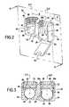
- the interconnecting device 10 of figures 2 and 3comprises a connecting body 12 and a hook member 14.
- the connecting body 12includes a first connecting member 16 and a second connecting member 18.
- the first connecting member 16, the second connecting member 18 and the hook member 14are formed as a single piece.
- the first connecting member 16, which forms a connecting headis provided with an opening which goes through the connecting head and terminates into, or opens into, two opposite faces of the head.
- said openingis a slot 20 which opens into two opposite side faces 22 and 24 of the head.
- the slot 20forms a passage going from a first side face 22 to a second side face 24 (which is opposite to the first one) of the first connecting member 16.
- the slot 20also opens into the upper end face of the first connecting member 16.
- the slot 20is defined between a bottom wall 26 which is substantially semi-cylindrical and two lateral walls 28 and 30 which are substantially straight.
- the lateral walls 28, 30extend parallel to the longitudinal axis XX' of the first connecting member 16.
- the upper portion 28a and 30a of the lateral walls 28 and 30defines portions of cylindrical surfaces. These upper portions 28a and 30a are provided with a threading 32.
- the threading 32is internal, but one skilled in the art will appreciate that it might be external.
- the hook member 14is formed by a hook 34.
- the hook member 14is a pedicle hook.
- the hook member 14may be a lamina hook.
- the hook 34is disposed below the first connecting head 16.
- the second connecting member 18is provided with an opening 40 which terminates into, or opens into, the side face 42 of the second connecting member 18.
- the opening 40also opens into the upper end face of the second connecting member 18.
- the bottom 44 of the opening 40is defined by a wall having substantially the shape of a portion of a half spherical surface.
- the partly spherical bottom 44 of the opening 40delimits the female part 48, or socket part, of a ball-and-socket joint.
- the upper part 46 of the opening 40is formed by a wall 48 having the shape of a portion of a cylindrical surface and extend parallel to the longitudinal axis YY' of the second connecting member 18.
- the upper part 46is provided with an internal threading 50.
- threading 50might be external.
- the first connecting member 16has a longitudinal axis XX' and the second connecting member 18 has a longitudinal axis YY'. These two axes are parallel one with the other and are disposed on a plane P.
- the plane Pforms a median plane for the interconnecting device 10.
- the first and second connecting members 16 and 18are placed side by side in the direction perpendicular to the direction of the axes XX' and YY'. As a result, the axes XX' and YY' are offset by a length E in the plane P.
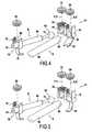
- the interconnecting device 10is used to form a spinal stabilizing system which combines a spinal construction system A, or spinal construction assembly, and an adjustable and autostable claw system B.
- the function of the device 10is to interconnect the extremity 60 of the spinal construction system A with an end 62 of a separate rod 64 which forms part of the autostable claw system B.
- the spinal construction system Ais symbolically represented by a longitudinal connecting rod 66 having a free end 60.
- the entire spinal construction Acomprises the connecting rod 66 and a plurality of fixing devices (not shown in the figure) to secure intermediate portions of the rod 66 with the vertebrae to be stabilized by the spinal construction system A.
- the free end 60 of the rod 66 of the spinal construction system Ais adapted to be engaged into the opening 20 of the first connecting member 16 of the interconnecting device 10.
- the diameter of the bottom wall 26 of the opening 20is slightly greater than the diameter D of the rod 66.
- the opening 20may receive the connecting rod 66 from both sides of the connecting member 16.
- the opening 20may receive the connecting rod 66 from both sides of the connecting member 16.
- itmakes the positioning of the interconnecting device 10 with respect to the connecting rod 66 easier.
- different layoutsmay be contemplated when implanting the device, as illustrated in FIGS 7A-7D and as described hereinafter. The device is, therefore, easily implantable by the physician or other operative.
- the end 62 of the separate rod 64is provided with a spherical member 70 which forms the male part, or ball member, of a ball-and-socket joint and is adapted to be engaged within the partially spherical female part 48 of the opening 40 of the second connecting member 18 forming the socket part of the ball-and-socket joint.
- the spherical member 70can be connected to the connecting member 18 by means of a screw 72 which can cooperate with the threading 50 of the opening of connecting member 18, the spherical member 70 being clamped between the screw 72 and the bottom 44 of the opening 40.
- the second end 74 of the separate rod 64can be connected to a fixing element 76.
- the fixing element 76comprises a connecting head 78 provided with a slot 80 to receive the rod 64 and a hook 79 to fix the fixing element 76 to a vertebra. It is therefore possible to cause the fixing element 76 to slip onto the separated rod 64 (before the locking step) and the fixing element 76 may be positioned more or less close to the tip of the separated rod 64.
- the length between the fixing element 76 and the second connecting member 18is adjustable and the device is easily implantable by the physician or other operative.
- the hook 79is a lamina hook.
- the second end 74 of the rod 64can be secured to the connecting head 78 by means of a screw 82.
- the interconnecting device 10is provided with a lamina hook 84.
- the hook member 34 or 84has the same axis XX' as, i.e. is "aligned" with, the first connecting member 16. However, it may be aligned with the second connecting member 18.
- a preferred use of the interconnecting device 10is to interconnect an autostable claw system B and a spinal construction system A.
- the autostable claw system Bcomprises the rod 64, the fixing element 76 with its hook 79, and the second connecting member 18 and the hook 34 of the interconnecting device 10.
- connection between the end 62, 70 of the separate rod 64 and the second connecting member 18is achieved by a ball-and-socket joint consisting in the spherical member 70 and the partially spherical bottom wall 44 of the connecting member 18.
- the direction of the separate rod 64can be chosen by the surgeon, or other operative, before screwing the screw 72 with the connecting member 18.
- the surgeoncan freely choose the part of the vertebra to which the fixing element 76 is fixed. This feature significantly simplifies the action of the surgeon as will be explained below with reference to figures 7A and 7D .
- the two connecting members 16 and 18are disposed side by side. Consequently, the interconnecting device is less aggressive than a device where the two connecting members are superposed.
- FIGS 7A to 7Dillustrate the great number of possible positions of the autostable claw system B and the spinal construction system A. These figures also illustrate the great number of possible fixing locations of the stabilizing system to the vertebrae.
- the interconnecting device 10 and the fixing element 76are both fixed to a lamina of vertebrae V1 and V2, and the autostable claw system B extends beyond the spinal construction system A.
- the angle C between the rods of the systems A and Bis substantially equal to 180 degrees.
- the fixing element 76is fixed to a lamina of vertebra V1 and the interconnecting device 10 is fixed to a pedicle of vertebra V2 and the angle C is approximately 150 degrees.
- the interconnecting device 10is fixed to a lamina of vertebra V1 and the fixing element 76 is secured to a pedicle of vertebra V2.
- the angle Cis about 10 degrees.
- the fixing element 76 and the interconnecting device 10are fixed to two different vertebrae. However, they may be fixed to the same vertebra.
- the separate rod 64 of system Bis smaller in length than the connecting rod 66 of system A and said separate rod 64 is designed so that said interconnecting device 10 and said fixing element 76 are mounted on the same vertebra or on two adjacent vertebrae.
- the connecting rod 66is designed so that more than two vertebrae are stabilized by the spinal construction system A.
- the separate rod 64has a straight shape and a desired length so that said interconnecting device 10 and said fixing element 76 are mounted on two adjacent vertebrae.
- said interconnecting device 10 and said fixing element 76are fixed to two different parts of the same vertebra.
- the rod 64 of the autostable claw system Bhas a reduced length.
Landscapes
- Health & Medical Sciences (AREA)
- Orthopedic Medicine & Surgery (AREA)
- Life Sciences & Earth Sciences (AREA)
- Neurology (AREA)
- Surgery (AREA)
- Heart & Thoracic Surgery (AREA)
- Engineering & Computer Science (AREA)
- Biomedical Technology (AREA)
- Nuclear Medicine, Radiotherapy & Molecular Imaging (AREA)
- Medical Informatics (AREA)
- Molecular Biology (AREA)
- Animal Behavior & Ethology (AREA)
- General Health & Medical Sciences (AREA)
- Public Health (AREA)
- Veterinary Medicine (AREA)
- Surgical Instruments (AREA)
- Prostheses (AREA)
Description
- The present invention relates to a stabilizing system according to claim 1. It comprises a device for interconnecting a connecting rod with a separate rod and fixing these rods to a bone.
- More particularly, it relates to a device for interconnecting a spinal construction assembly comprising a connecting rod with a separate rod and fixing them to a vertebra, and a stabilizing system including such an interconnecting device.
- One field of application for the invention is holding bones in a relative position, for example, to aid in the healing of breaks or the positioning of bones, or the treatment of scoliosis, or otherwise to correct abnormal curvatures of the spine.
- The spine is formed of superposed vertebrae, normally aligned along a vertebral axis from the lumbar vertebrae to the cervical vertebrae, each having a posterior wall from which projects a spinous process and two lateral edges from the walls of which project ribs and/or transverse process. Each vertebra also has two lateral pedicles and lamina surfaces.
- Accompanying
figure 1 shows vertebrae V and V' with the different parts thereof. Reference TP designates the transversal processes, reference P designates the pedicles of the vertebra and reference L designates the lamina. - In order to straighten or stabilize the vertebrae of a spine it is well known to use a stabilizing system which includes a longitudinal connecting rod and several fixing elements. Each fixing element is secured to one of the vertebrae to be stabilized and the connecting rod is secured to each fixing element, so that portions of the connecting rod are secured to the vertebrae to be stabilized. The fixing elements include a head to be secured to the rod and a fixing member which may consist of a screw (for example a pedicle screw) or a hook. When the patient who is equipped with such a stabilizing system moves his spine, forces are developed by the fixing members of the fixing elements in the vertebrae. In particular, the fixing elements disposed at the extremities of the rod of the stabilizing system or spinal construction assembly, develop the greatest forces. It is therefore apparent that it would be advantageous to try to decrease the forces developed at the extremities of the spinal construction assembly.
- Moreover, autostable claw systems are also well known. Such a system is described, for example, in
EP 0 571 619 . This system includes two fixing elements, each one being provided with a hook member, and a rod to interconnect the fixing elements and, consequently, the vertebrae on which the fixing elements are secured. When defining with the rod the appropriate distance between the two fixing elements, an appropriate stabilization of the vertebrae is obtained. - Document
WO9715231A - In another use of the autostable claw system, the hook members of the autostable claw system can be secured to different parts of the same vertebra.
- A first goal is to provide an interconnecting device which is more easily implantable by the physician than the already known devices, such a device being intended, in particular, for interconnecting a spinal construction assembly, more particularly the extremity of said assembly, with a separate rod, said separate rod being preferably, but not necessarily, part of an autostable claw system.
- To achieve this goal, according to the one embodiment of the present disclosure, there is provided a stabilizing system comprising a device for interconnecting a connecting rod with a separate rod and fixing them to a bone, this device comprising a connecting body and a hook member for securing said connecting body to said bone, said hook member being fixed to said connecting body, said connecting body comprising a first connecting member and a second connecting member, said first connecting member being adapted to receive a connecting rod, said second connecting member being adapted to receive a first end of a separate rod so that the direction of the separate rod is adaptable with respect to the direction of the connecting rod.
- Said connecting rod is part of a spinal construction assembly, and said bone is a vertebra. Accordingly, the spinal construction system assembly and, in particular, the extremity of this assembly, is connected to one end of the separate rod and fixed to the vertebra thanks to the interconnecting device, which is a unique device.
- Due to the fact that the second connecting member allows the separate rod to have an adaptable direction with respect to the direction of the connecting rod, the surgeon (or other operative) can choose freely the part of the vertebra to which the interconnecting device is fixed.
- According to the invention, there is provided a device for interconnecting a connecting rod with a separate rod and fixing these rods to a vertebra, this device being such that it comprises a connecting body, and a hook member for securing the connecting body to a bone, the hook member being fixed to the connecting body; such that said connecting body comprises a first connecting member, and a second connecting member; and such that said first connecting member has a slot adapted to receive a connecting rod, said slot opening into two opposite side faces of the first connecting member, so that said slot may receive the connecting rod from both sides of the first connecting member, and such that said second connecting member is adapted to receive a first end of a separate rod, in a manner that the direction of the separate rod is adaptable with respect to the direction of the connecting rod.
- The interconnecting device may be used for interconnecting a free end of a connecting rod with a separate rod, the slot of said first connecting member being adapted to receive the free end of the connecting rod.
- According to an embodiment, the second connecting member is provided with an opening which opens into at least one side face of the second connecting member, said opening forming a socket part of a ball-and-socket joint and being configured to receive a ball end of a separate rod. Said ball-and-socket joint can also be called "rotulating assembly".
- According to an embodiment, said opening has a partially spherical bottom wall delimiting said socket part.
- According to an embodiment, the first end of the separate rod is provided with a spherical member which forms the ball member, or male part, of said ball-and-socket joint, and the second connecting member is provided with an opening which terminates into, i.e. opens into, a side face of the second connecting member, this opening having a partially spherical bottom wall which forms the socket part, or female part, of said ball-and-socket joint, said ball member being adapted to be engaged within said socket part.
- According to an embodiment, said hook member and said connecting body have a common median plane, said first connecting member having an axis and overlapping said hook member, said second connecting member having an axis contained in said median plane and substantially parallel to the axis of the first connecting member and being offset with respect to said first connecting member in a direction perpendicular to the axis of said first connecting member.
- Because the second connecting member is offset with respect to the first connecting member in a direction which is perpendicular to the direction of the axis of the connecting member, the thickness of the head of the interconnecting device is not increased.
- The hook member may overlap the first connecting member or the second connecting member in a direction which is substantially parallel to the axis of the first connecting member.
- According to an embodiment, the first connecting member overlaps the hook member in a direction which is substantially parallel to the axis of the first connecting member.
- According to an embodiment, the opening of the second connecting member opens into two opposite side faces of the second connecting member, so that said opening is adapted to receive the first end of a separate rod from both sides of the second connecting member, i.e. from both sides with respect to said median plane.
- Another objective is to provide a stabilizing system with an interconnecting device such as described above.
- Thus, there is provided a stabilizing system comprising a spinal construction assembly, a separate rod having first and second ends, an interconnecting device such as described above for interconnecting said spinal construction assembly and the first end of said separate rod.
- According to one embodiment of the disclosure, there is provided a stabilizing system for stabilizing vertebrae comprising:
- a spinal construction assembly comprising a connecting rod;
- a separate rod having first and second ends; and
- an interconnecting device such as described above, for interconnecting said connecting rod with the first end of said separate rod, the connecting body of the interconnecting device being intended to be secured to a vertebra.
- The spinal construction assembly comprises a plurality of fixing devices to secure portions of the connecting rod with the vertebrae to be stabilized.
- The stabilizing system further comprises a fixing element for fixing said separate rod to a vertebra and, more particularly, for fixing the second end of said separate rod to a vertebra.
- It should be noted that the stabilizing system is basically a combination of a spinal construction system and of an autostable claw system, this autostable claw system being formed by the second connecting member of the interconnecting device, the separate rod, and the fixing element. The purpose of the autostable claw system is to obtain a decrease in the forces developed within the vertebra by the extremity of the spinal construction system.
- According to an embodiment, the separate rod is designed so that said interconnecting device and said fixing element are mounted on the same vertebra.
- According to another embodiment, the separate rod is designed so that said interconnecting device and said fixing element are mounted on two adjacent vertebrae.
- As the separate rod can have an adaptable direction with respect to the direction of the rod of the spinal construction, the surgeon can freely choose the part of the vertebra to which the interconnecting device is fixed and the part of the vertebra to which the fixing element is secured. This part can be the transverse process, the pedicle or the lamina. The hook member of the interconnecting device and the fixing member (which may be another hook member) of the fixing element can be fixed to two different parts of the same vertebra or to two adjacent different vertebrae.
- In both cases, the rods of the spinal construction and of the separate rod can form an angle of less than 90 degrees. This means that the separate rod "returns" towards the rod of the spinal construction.
- In both cases, the angle between the two rods can also be more than 90 degrees. This means that the separate rod extends "beyond" the rod of the spinal construction.
- The accompanying drawings are not necessarily to scale, emphasis instead generally being placed upon illustrating the principles of the invention.
Figure 1 , already described, is a perspective view of two vertebrae showing the different parts of the vertebrae.Figure 2 is a perspective view of an example of interconnecting device according to the present disclosure.Figure 3 is a sectional view of the interconnecting device according to plane P offigure 2 .Figure 4 is an exploded view showing the combination of a spinal construction assembly with a separate rod, the interconnecting device being provided with a pedicle hook.Figure 5 is similar tofigure 4 but the interconnecting device is provided with a lamina hook.Figure 6 is similar tofigure 4 but with the components assembled.Figures 7A to 7D are schematic drawings which show four different combinations of a spinal construction assembly with an autostable claw system.- In the following detailed description, it is referred to the accompanying drawings showing examples of interconnecting device and stabilizing system according to the present disclosure. It is intended that these examples are to be considered only as illustrations of the invention. The invention is not limited to these examples.
- The interconnecting
device 10 offigures 2 and 3 , comprises a connectingbody 12 and ahook member 14. - The connecting
body 12 includes a first connectingmember 16 and a second connectingmember 18. Preferably, the first connectingmember 16, the second connectingmember 18 and thehook member 14 are formed as a single piece. - Preferably, the first connecting
member 16, which forms a connecting head, is provided with an opening which goes through the connecting head and terminates into, or opens into, two opposite faces of the head. In the example offigures 2 and 3 , said opening is aslot 20 which opens into two opposite side faces 22 and 24 of the head. Thus, theslot 20 forms a passage going from afirst side face 22 to a second side face 24 (which is opposite to the first one) of the first connectingmember 16. Theslot 20 also opens into the upper end face of the first connectingmember 16. Theslot 20 is defined between abottom wall 26 which is substantially semi-cylindrical and twolateral walls lateral walls member 16. - The
upper portion lateral walls upper portions - Preferably, the
hook member 14 is formed by ahook 34. In the embodiment shown infigure 2 , thehook member 14 is a pedicle hook. However, thehook member 14 may be a lamina hook. Thehook 34 is disposed below the first connectinghead 16. - Preferably, the second connecting
member 18 is provided with anopening 40 which terminates into, or opens into, theside face 42 of the second connectingmember 18. Theopening 40 also opens into the upper end face of the second connectingmember 18. The bottom 44 of theopening 40 is defined by a wall having substantially the shape of a portion of a half spherical surface. As will be explained hereinafter, the partlyspherical bottom 44 of theopening 40 delimits the female part 48, or socket part, of a ball-and-socket joint. - The
upper part 46 of theopening 40 is formed by a wall 48 having the shape of a portion of a cylindrical surface and extend parallel to the longitudinal axis YY' of the second connectingmember 18. Theupper part 46 is provided with aninternal threading 50. One skilled in the art will appreciate that threading 50 might be external. - The first connecting
member 16 has a longitudinal axis XX' and the second connectingmember 18 has a longitudinal axis YY'. These two axes are parallel one with the other and are disposed on a plane P. The plane P forms a median plane for the interconnectingdevice 10. The first and second connectingmembers - Referring now to
figure 4 , the interconnectingdevice 10 is used to form a spinal stabilizing system which combines a spinal construction system A, or spinal construction assembly, and an adjustable and autostable claw system B. The function of thedevice 10 is to interconnect theextremity 60 of the spinal construction system A with anend 62 of aseparate rod 64 which forms part of the autostable claw system B. - In
figure 4 , the spinal construction system A is symbolically represented by a longitudinal connectingrod 66 having afree end 60. As is well known, the entire spinal construction A comprises the connectingrod 66 and a plurality of fixing devices (not shown in the figure) to secure intermediate portions of therod 66 with the vertebrae to be stabilized by the spinal construction system A. - The
free end 60 of therod 66 of the spinal construction system A is adapted to be engaged into theopening 20 of the first connectingmember 16 of the interconnectingdevice 10. For this purpose, the diameter of thebottom wall 26 of theopening 20 is slightly greater than the diameter D of therod 66. When theend 60 of therod 66 is engaged into theslot 20, thisend 60 is connected to the connecting member by means of ascrew 68 which cooperates with the threading 32, therod 66 being clamped between thescrew 68 and thebottom wall 26 of theopening 20. - The
opening 20 may receive the connectingrod 66 from both sides of the connectingmember 16. Thus, it makes the positioning of the interconnectingdevice 10 with respect to the connectingrod 66 easier. In particular, it is possible to cause the interconnectingdevice 10 to slip onto the connecting rod 66 (before the locking step) and, thus, the connectingmember 16 may be positioned more or less close to the tip of the connectingrod 66. Moreover, different layouts may be contemplated when implanting the device, as illustrated inFIGS 7A-7D and as described hereinafter. The device is, therefore, easily implantable by the physician or other operative. - As shown in
figure 4 , theend 62 of theseparate rod 64 is provided with aspherical member 70 which forms the male part, or ball member, of a ball-and-socket joint and is adapted to be engaged within the partially spherical female part 48 of theopening 40 of the second connectingmember 18 forming the socket part of the ball-and-socket joint. Thespherical member 70 can be connected to the connectingmember 18 by means of ascrew 72 which can cooperate with the threading 50 of the opening of connectingmember 18, thespherical member 70 being clamped between thescrew 72 and the bottom 44 of theopening 40. - The
second end 74 of theseparate rod 64 can be connected to a fixingelement 76. Preferably, the fixingelement 76 comprises a connectinghead 78 provided with aslot 80 to receive therod 64 and ahook 79 to fix the fixingelement 76 to a vertebra. It is therefore possible to cause the fixingelement 76 to slip onto the separated rod 64 (before the locking step) and the fixingelement 76 may be positioned more or less close to the tip of the separatedrod 64. Thus, the length between the fixingelement 76 and the second connectingmember 18 is adjustable and the device is easily implantable by the physician or other operative. - In the example shown in
figure 4 , thehook 79 is a lamina hook. - The
second end 74 of therod 64 can be secured to the connectinghead 78 by means of ascrew 82. - In
figure 5 , the interconnectingdevice 10 is provided with alamina hook 84. - In the figures, the
hook member member 16. However, it may be aligned with the second connectingmember 18. - A preferred use of the interconnecting
device 10 is to interconnect an autostable claw system B and a spinal construction system A. - The autostable claw system B comprises the
rod 64, the fixingelement 76 with itshook 79, and the second connectingmember 18 and thehook 34 of the interconnectingdevice 10. - As already explained, the connection between the
end separate rod 64 and the second connectingmember 18 is achieved by a ball-and-socket joint consisting in thespherical member 70 and the partiallyspherical bottom wall 44 of the connectingmember 18. As a result, the direction of theseparate rod 64 can be chosen by the surgeon, or other operative, before screwing thescrew 72 with the connectingmember 18. Thus, the surgeon can freely choose the part of the vertebra to which the fixingelement 76 is fixed. This feature significantly simplifies the action of the surgeon as will be explained below with reference tofigures 7A and 7D . - Moreover, the two connecting
members Figures 7A to 7D illustrate the great number of possible positions of the autostable claw system B and the spinal construction system A. These figures also illustrate the great number of possible fixing locations of the stabilizing system to the vertebrae.- In the case of
figure 7A , the interconnectingdevice 10 and the fixingelement 76 are both fixed to a lamina of vertebrae V1 and V2, and the autostable claw system B extends beyond the spinal construction system A. The angle C between the rods of the systems A and B is substantially equal to 180 degrees. - In the case of
figure 7B , the interconnectingdevice 10 and the fixingelement 76 are still secured to a lamina of vertebrae V1 and V2 but the angle C between the autostable claw system B and the spinal construction system A is greatly reduced. The rods of the systems A and B are substantially parallel and the system B "returns" towards the system A. - In the case of
figure 7C , the fixingelement 76 is fixed to a lamina of vertebra V1 and the interconnectingdevice 10 is fixed to a pedicle of vertebra V2 and the angle C is approximately 150 degrees. - Finally, in the case of
figure 7D , the interconnectingdevice 10 is fixed to a lamina of vertebra V1 and the fixingelement 76 is secured to a pedicle of vertebra V2. The angle C is about 10 degrees. - In the examples of
figures 7A to 7D , the fixingelement 76 and the interconnectingdevice 10 are fixed to two different vertebrae. However, they may be fixed to the same vertebra. - The
separate rod 64 of system B is smaller in length than the connectingrod 66 of system A and saidseparate rod 64 is designed so that said interconnectingdevice 10 and said fixingelement 76 are mounted on the same vertebra or on two adjacent vertebrae. The connectingrod 66 is designed so that more than two vertebrae are stabilized by the spinal construction system A. - In the examples of
figures 7A to 7D , theseparate rod 64 has a straight shape and a desired length so that said interconnectingdevice 10 and said fixingelement 76 are mounted on two adjacent vertebrae. - In another embodiment (not shown), said interconnecting
device 10 and said fixingelement 76 are fixed to two different parts of the same vertebra. In this case, therod 64 of the autostable claw system B has a reduced length. - In both cases, the anchoring of the extremity of the spinal construction system A into the vertebra is improved by the provision of the autostable claw system B.
Claims (13)
- A stabilizing system for stabilizing vertebrae comprising:- a spinal construction assembly comprising a connecting rod (66) and a plurality of fixing devices to secure portions of the connecting rod (66) with the vertebrae to be stabilized;
the stabilizing system further comprising:- a separate rod (64) having first and second ends (62, 74);
and- an interconnecting device (10) for interconnecting said connecting rod (66) with the first end (62) of said separate rod (64) and fixing these rods (64, 66) to a vertebra, this interconnecting device comprising:wherein the first connecting member (16) has a slot (20) adapted to receive said connecting rod (66), said slot (20) opening into two opposite side faces (22, 24) of the first connecting member (16),- a connecting body (12), and- a hook member (14) for securing said connecting body (12) to a vertebra, said hook member (14) being fixed to said connecting body (12),
said connecting body (12) comprising:- a first connecting member (16), and- a second connecting member (18),
characterized in that
the stabilizing system further comprises- a fixing element (76) for fixing the second end (74) of said separate rod (64) to a vertebra, this fixing element (76) being distinct from said fixing devices;andin that the second connecting member (18) is adapted to receive the first end (62) of said separate rod (64), in a manner that the direction of the separate rod (64) is adaptable with respect to the direction of the connecting rod (66). - The stabilizing system of claim 1, wherein the second connecting member (18) is provided with an opening (40) which opens into at least one side face (42) of the second connecting member (18), said opening (40) forming a socket part of a ball-and-socket joint and being configured to receive a ball end of a separate rod (64).
- The stabilizing system of claim 2, wherein said opening (40) has a partially spherical bottom wall (44) which delimits said socket part.
- The stabilizing system of any one of claims 1 to 3, wherein said opening (40) opens into two opposite side faces of the second connecting member (18).
- The stabilizing system of any one of claims 1 to 4, wherein said hook member (14) and said connecting body (12) have a common median plane (P); said first connecting member (16) has an axis (XX'); and said second connecting member (18) has an axis (YY') contained in said median plane and substantially parallel to the axis (XX') of the first connecting member (18) and being offset with respect to said first connecting member in a direction perpendicular to the axis (XX') of said first connecting member.
- The stabilizing system of claim 5, wherein said first connecting member (16) overlaps said hook member in a direction which is substantially parallel to the axis (XX') of the first connecting member (16).
- The stabilizing system of any one of claims 1 to 6, wherein the connecting rod (66) is designed so that more than two vertebrae are stabilized by the spinal construction assembly.
- The stabilizing system of any one of claims 1 to 7, wherein the first end (62) of the separate rod (64) forms a ball member of a ball-and-socket joint.
- The stabilizing system of any one of claims 1 to 8, wherein said fixing element (76) includes a hook member which is, in particular, a lamina hook member or a pedicle hook member.
- The stabilizing system of any one of claims 1 to 9, wherein said separate rod (64) is smaller in length than said connecting rod (66), said separate rod (64) being designed so that said interconnecting device (10) and said fixing element (76) are mounted on the same vertebra or on two adjacent vertebrae.
- The stabilizing system of any one of claims 1 to 10 for interconnecting a free end of the connecting rod (66) with the separate rod (64), the slot (20) of the first connecting member (16) being adapted to receive the free end of the connecting rod (66).
- The stabilizing system of any one of claims 1 to 11, wherein the second connecting member (18) and the first end (62) of the separate rod (64) are connected via a ball-and-socket joint.
- The stabilizing system of claim 12, wherein the second connecting member (18) comprises a socket part and wherein the first end (62) of the separate rod (64) has a ball shape, thereby forming a ball member, the socket part cooperating with the ball member for forming said ball-and-socket joint.
Priority Applications (1)
| Application Number | Priority Date | Filing Date | Title |
|---|---|---|---|
| EP09820276.5AEP2370011B1 (en) | 2008-10-15 | 2009-09-29 | A spinal construction assembly comprising an interconnecting device |
Applications Claiming Priority (3)
| Application Number | Priority Date | Filing Date | Title |
|---|---|---|---|
| EP08305684 | 2008-10-15 | ||
| PCT/EP2009/062630WO2010043496A1 (en) | 2008-10-15 | 2009-09-29 | Interconnecting device for a spinal construction assembly |
| EP09820276.5AEP2370011B1 (en) | 2008-10-15 | 2009-09-29 | A spinal construction assembly comprising an interconnecting device |
Publications (2)
| Publication Number | Publication Date |
|---|---|
| EP2370011A1 EP2370011A1 (en) | 2011-10-05 |
| EP2370011B1true EP2370011B1 (en) | 2013-04-10 |
Family
ID=40257087
Family Applications (1)
| Application Number | Title | Priority Date | Filing Date |
|---|---|---|---|
| EP09820276.5ANot-in-forceEP2370011B1 (en) | 2008-10-15 | 2009-09-29 | A spinal construction assembly comprising an interconnecting device |
Country Status (4)
| Country | Link |
|---|---|
| US (1) | US20100234892A1 (en) |
| EP (1) | EP2370011B1 (en) |
| ES (1) | ES2417308T3 (en) |
| WO (1) | WO2010043496A1 (en) |
Cited By (1)
| Publication number | Priority date | Publication date | Assignee | Title |
|---|---|---|---|---|
| CN109803598A (en)* | 2016-10-11 | 2019-05-24 | 华沙整形外科股份有限公司 | Spinal implant system and method |
Families Citing this family (9)
| Publication number | Priority date | Publication date | Assignee | Title |
|---|---|---|---|---|
| WO2009097623A2 (en)* | 2008-02-02 | 2009-08-06 | Texas Scottish Rite Hospital For Children | Pedicle screw |
| US9345517B2 (en)* | 2008-02-02 | 2016-05-24 | Globus Medical, Inc. | Pedicle screw having a removable rod coupling |
| EP2468200A1 (en) | 2010-12-21 | 2012-06-27 | Zimmer Spine | Orthopaedic device and methods for its pre-assembly and assembly |
| WO2012138852A1 (en)* | 2011-04-08 | 2012-10-11 | Aesculap Implant Systems, Llc | Articulating rod assembly |
| US8758411B1 (en) | 2011-10-25 | 2014-06-24 | Nuvasive, Inc. | Implants and methods for treating spinal disorders |
| US9232966B2 (en)* | 2012-09-24 | 2016-01-12 | Refai Technologies, Llc | Articulating spinal rod system |
| EP2762095B1 (en) | 2013-01-31 | 2016-05-25 | Zimmer Spine | Device for fixing a bony structure to a support member |
| GB2512063B (en)* | 2013-03-18 | 2019-05-29 | Fitzbionics Ltd | Spinal implant assembly |
| US10575876B2 (en) | 2016-04-20 | 2020-03-03 | K2M, Inc. | Spinal stabilization assemblies with bone hooks |
Family Cites Families (26)
| Publication number | Priority date | Publication date | Assignee | Title |
|---|---|---|---|---|
| US5688273A (en)* | 1995-10-23 | 1997-11-18 | Fastenetix, Llc. | Spinal implant apparatus having a single central rod and plow hooks |
| WO1997015231A1 (en)* | 1995-10-23 | 1997-05-01 | Fastenetix, L.L.C. | A spinal implant device having a single central rod and plow and/or claw hooks |
| FR2767263B1 (en)* | 1997-08-13 | 1999-10-01 | Aesculap Jbs | CLAMPS FOR VERTEBRAL OSTEOSYNTHESIS SYSTEM |
| US20020133155A1 (en)* | 2000-02-25 | 2002-09-19 | Ferree Bret A. | Cross-coupled vertebral stabilizers incorporating spinal motion restriction |
| AU2001270720B2 (en)* | 2000-06-30 | 2007-02-08 | Henry Graf | Intervertebral linking device |
| JP2004505745A (en)* | 2000-08-24 | 2004-02-26 | ジンテーズ アクチエンゲゼルシャフト クール | Device for connecting a bone anchoring element to a longitudinal rod |
| FR2820968A1 (en)* | 2001-02-20 | 2002-08-23 | Charles Khalife | Spinal osteosynthesis implant has hollow locking nut with inner thread for forked upper end of pedicular screw or hook containing linking rod |
| US6802844B2 (en)* | 2001-03-26 | 2004-10-12 | Nuvasive, Inc | Spinal alignment apparatus and methods |
| US20060079892A1 (en)* | 2001-10-31 | 2006-04-13 | Suranjan Roychowdhury | Adjustable tandem connectors for corrective devices for the spinal column and other bones and joints |
| FR2835174B1 (en)* | 2002-01-31 | 2004-03-19 | Materiel Orthopedique En Abreg | CONNECTOR FOR SPINAL OSTEOSYNTHESIS DEVICE, BONE ANCHOR CONNECTOR / MEMBER ASSEMBLY AND SPINAL OSTEOSYNTHESIS DEVICE USING THE SAME |
| US20040111088A1 (en)* | 2002-12-06 | 2004-06-10 | Picetti George D. | Multi-rod bone attachment member |
| FR2849590B1 (en)* | 2003-01-07 | 2005-03-18 | Eurosurgical | RACHIDIAN IMPLANT WITH HOOKS |
| FR2856270B1 (en)* | 2003-06-17 | 2006-02-10 | Eurosurgical | PEDICULAR HOOKS FOR SPINAL INK DEVICE. |
| US20050277934A1 (en)* | 2004-06-10 | 2005-12-15 | Vardiman Arnold B | Rod delivery device and method |
| US8034082B2 (en)* | 2004-07-08 | 2011-10-11 | Globus Medical, Inc. | Transverse fixation device for spinal fixation systems |
| US7485133B2 (en)* | 2004-07-14 | 2009-02-03 | Warsaw Orthopedic, Inc. | Force diffusion spinal hook |
| US20070239159A1 (en)* | 2005-07-22 | 2007-10-11 | Vertiflex, Inc. | Systems and methods for stabilization of bone structures |
| US8226690B2 (en)* | 2005-07-22 | 2012-07-24 | The Board Of Trustees Of The Leland Stanford Junior University | Systems and methods for stabilization of bone structures |
| US8029545B2 (en)* | 2006-02-07 | 2011-10-04 | Warsaw Orthopedic Inc. | Articulating connecting member and anchor systems for spinal stabilization |
| US8435267B2 (en)* | 2006-04-24 | 2013-05-07 | Spinefrontier Inc | Spine fixation method and apparatus |
| US20080058805A1 (en)* | 2006-08-28 | 2008-03-06 | Microdexterity Systems, Inc. | Spinal fusion implant |
| US7922746B2 (en)* | 2006-08-31 | 2011-04-12 | Warsaw Orthopedic, Inc. | Spinal rod extenders and methods of use |
| US7842074B2 (en)* | 2007-02-26 | 2010-11-30 | Abdou M Samy | Spinal stabilization systems and methods of use |
| US8337527B2 (en)* | 2007-04-18 | 2012-12-25 | Ebi, Llc | Spinal connector |
| US8313515B2 (en)* | 2007-06-15 | 2012-11-20 | Rachiotek, Llc | Multi-level spinal stabilization system |
| US8298266B2 (en)* | 2008-04-11 | 2012-10-30 | Warsaw Orthopedic, Inc. | Connectors for elongated surgical members and methods of use |
- 2009
- 2009-09-29EPEP09820276.5Apatent/EP2370011B1/ennot_activeNot-in-force
- 2009-09-29WOPCT/EP2009/062630patent/WO2010043496A1/enactiveApplication Filing
- 2009-09-29ESES09820276Tpatent/ES2417308T3/enactiveActive
- 2009-10-15USUS12/580,202patent/US20100234892A1/ennot_activeAbandoned
Cited By (2)
| Publication number | Priority date | Publication date | Assignee | Title |
|---|---|---|---|---|
| CN109803598A (en)* | 2016-10-11 | 2019-05-24 | 华沙整形外科股份有限公司 | Spinal implant system and method |
| CN109803598B (en)* | 2016-10-11 | 2023-02-17 | 华沙整形外科股份有限公司 | Spinal implant system and method |
Also Published As
| Publication number | Publication date |
|---|---|
| WO2010043496A1 (en) | 2010-04-22 |
| ES2417308T3 (en) | 2013-08-07 |
| EP2370011A1 (en) | 2011-10-05 |
| US20100234892A1 (en) | 2010-09-16 |
Similar Documents
| Publication | Publication Date | Title |
|---|---|---|
| EP2370011B1 (en) | A spinal construction assembly comprising an interconnecting device | |
| US10098667B2 (en) | Orthopaedic device and methods for its pre-assembly and assembly | |
| US8414621B2 (en) | Modular system for the stabilization of the spinal column | |
| US8382805B2 (en) | Bone screw assembly for limited angulation | |
| EP2769692B1 (en) | Iliosacral polyaxial screw | |
| US7163539B2 (en) | Biased angle polyaxial pedicle screw assembly | |
| EP3409225B1 (en) | Vertebral stabilization system | |
| EP1991144B1 (en) | Dorsal adjusting spinal connector assembly | |
| EP2010079B1 (en) | Connector apparatus | |
| US7794478B2 (en) | Polyaxial cross connector and methods of use thereof | |
| EP1600111B1 (en) | Device for connecting the rod of a spinal osteosynthesis device to a vertebra, and osteosynthesis system comprising this device | |
| US20080114400A1 (en) | System for spine osteosynthesis | |
| US20060052784A1 (en) | Polyaxial device for spine stabilization during osteosynthesis | |
| US8591551B2 (en) | Linked spinal stabilization elements for spinal fixation | |
| WO2002022030A2 (en) | Posterior fixation system | |
| AU2001289108A1 (en) | Posterior fixation system | |
| EP3193755B1 (en) | Fusion systems of assembly and use | |
| EP4033994B1 (en) | Spinal fixation device with rotatable connector | |
| JP2001245896A (en) | Rod retainer |
Legal Events
| Date | Code | Title | Description |
|---|---|---|---|
| PUAI | Public reference made under article 153(3) epc to a published international application that has entered the european phase | Free format text:ORIGINAL CODE: 0009012 | |
| 17P | Request for examination filed | Effective date:20110512 | |
| AK | Designated contracting states | Kind code of ref document:A1 Designated state(s):AT BE BG CH CY CZ DE DK EE ES FI FR GB GR HR HU IE IS IT LI LT LU LV MC MK MT NL NO PL PT RO SE SI SK SM TR | |
| DAX | Request for extension of the european patent (deleted) | ||
| GRAP | Despatch of communication of intention to grant a patent | Free format text:ORIGINAL CODE: EPIDOSNIGR1 | |
| GRAS | Grant fee paid | Free format text:ORIGINAL CODE: EPIDOSNIGR3 | |
| GRAA | (expected) grant | Free format text:ORIGINAL CODE: 0009210 | |
| AK | Designated contracting states | Kind code of ref document:B1 Designated state(s):AT BE BG CH CY CZ DE DK EE ES FI FR GB GR HR HU IE IS IT LI LT LU LV MC MK MT NL NO PL PT RO SE SI SK SM TR | |
| REG | Reference to a national code | Ref country code:GB Ref legal event code:FG4D | |
| REG | Reference to a national code | Ref country code:AT Ref legal event code:REF Ref document number:605531 Country of ref document:AT Kind code of ref document:T Effective date:20130415 Ref country code:CH Ref legal event code:EP | |
| REG | Reference to a national code | Ref country code:CH Ref legal event code:NV Representative=s name:ZIMMER GMBH PATENTS AND TRADEMARKS, CH | |
| REG | Reference to a national code | Ref country code:IE Ref legal event code:FG4D | |
| REG | Reference to a national code | Ref country code:DE Ref legal event code:R096 Ref document number:602009014960 Country of ref document:DE Effective date:20130606 | |
| REG | Reference to a national code | Ref country code:ES Ref legal event code:FG2A Ref document number:2417308 Country of ref document:ES Kind code of ref document:T3 Effective date:20130807 | |
| PG25 | Lapsed in a contracting state [announced via postgrant information from national office to epo] | Ref country code:SI Free format text:LAPSE BECAUSE OF FAILURE TO SUBMIT A TRANSLATION OF THE DESCRIPTION OR TO PAY THE FEE WITHIN THE PRESCRIBED TIME-LIMIT Effective date:20130410 | |
| REG | Reference to a national code | Ref country code:AT Ref legal event code:MK05 Ref document number:605531 Country of ref document:AT Kind code of ref document:T Effective date:20130410 | |
| REG | Reference to a national code | Ref country code:LT Ref legal event code:MG4D Ref country code:NL Ref legal event code:VDEP Effective date:20130410 | |
| PG25 | Lapsed in a contracting state [announced via postgrant information from national office to epo] | Ref country code:FI Free format text:LAPSE BECAUSE OF FAILURE TO SUBMIT A TRANSLATION OF THE DESCRIPTION OR TO PAY THE FEE WITHIN THE PRESCRIBED TIME-LIMIT Effective date:20130410 Ref country code:SE Free format text:LAPSE BECAUSE OF FAILURE TO SUBMIT A TRANSLATION OF THE DESCRIPTION OR TO PAY THE FEE WITHIN THE PRESCRIBED TIME-LIMIT Effective date:20130410 Ref country code:IS Free format text:LAPSE BECAUSE OF FAILURE TO SUBMIT A TRANSLATION OF THE DESCRIPTION OR TO PAY THE FEE WITHIN THE PRESCRIBED TIME-LIMIT Effective date:20130810 Ref country code:AT Free format text:LAPSE BECAUSE OF FAILURE TO SUBMIT A TRANSLATION OF THE DESCRIPTION OR TO PAY THE FEE WITHIN THE PRESCRIBED TIME-LIMIT Effective date:20130410 Ref country code:NO Free format text:LAPSE BECAUSE OF FAILURE TO SUBMIT A TRANSLATION OF THE DESCRIPTION OR TO PAY THE FEE WITHIN THE PRESCRIBED TIME-LIMIT Effective date:20130710 Ref country code:GR Free format text:LAPSE BECAUSE OF FAILURE TO SUBMIT A TRANSLATION OF THE DESCRIPTION OR TO PAY THE FEE WITHIN THE PRESCRIBED TIME-LIMIT Effective date:20130711 Ref country code:PT Free format text:LAPSE BECAUSE OF FAILURE TO SUBMIT A TRANSLATION OF THE DESCRIPTION OR TO PAY THE FEE WITHIN THE PRESCRIBED TIME-LIMIT Effective date:20130812 Ref country code:LT Free format text:LAPSE BECAUSE OF FAILURE TO SUBMIT A TRANSLATION OF THE DESCRIPTION OR TO PAY THE FEE WITHIN THE PRESCRIBED TIME-LIMIT Effective date:20130410 Ref country code:NL Free format text:LAPSE BECAUSE OF FAILURE TO SUBMIT A TRANSLATION OF THE DESCRIPTION OR TO PAY THE FEE WITHIN THE PRESCRIBED TIME-LIMIT Effective date:20130410 Ref country code:BE Free format text:LAPSE BECAUSE OF FAILURE TO SUBMIT A TRANSLATION OF THE DESCRIPTION OR TO PAY THE FEE WITHIN THE PRESCRIBED TIME-LIMIT Effective date:20130410 | |
| PG25 | Lapsed in a contracting state [announced via postgrant information from national office to epo] | Ref country code:CY Free format text:LAPSE BECAUSE OF FAILURE TO SUBMIT A TRANSLATION OF THE DESCRIPTION OR TO PAY THE FEE WITHIN THE PRESCRIBED TIME-LIMIT Effective date:20130410 Ref country code:PL Free format text:LAPSE BECAUSE OF FAILURE TO SUBMIT A TRANSLATION OF THE DESCRIPTION OR TO PAY THE FEE WITHIN THE PRESCRIBED TIME-LIMIT Effective date:20130410 Ref country code:LV Free format text:LAPSE BECAUSE OF FAILURE TO SUBMIT A TRANSLATION OF THE DESCRIPTION OR TO PAY THE FEE WITHIN THE PRESCRIBED TIME-LIMIT Effective date:20130410 Ref country code:BG Free format text:LAPSE BECAUSE OF FAILURE TO SUBMIT A TRANSLATION OF THE DESCRIPTION OR TO PAY THE FEE WITHIN THE PRESCRIBED TIME-LIMIT Effective date:20130710 Ref country code:HR Free format text:LAPSE BECAUSE OF FAILURE TO SUBMIT A TRANSLATION OF THE DESCRIPTION OR TO PAY THE FEE WITHIN THE PRESCRIBED TIME-LIMIT Effective date:20130410 | |
| PG25 | Lapsed in a contracting state [announced via postgrant information from national office to epo] | Ref country code:EE Free format text:LAPSE BECAUSE OF FAILURE TO SUBMIT A TRANSLATION OF THE DESCRIPTION OR TO PAY THE FEE WITHIN THE PRESCRIBED TIME-LIMIT Effective date:20130410 Ref country code:CZ Free format text:LAPSE BECAUSE OF FAILURE TO SUBMIT A TRANSLATION OF THE DESCRIPTION OR TO PAY THE FEE WITHIN THE PRESCRIBED TIME-LIMIT Effective date:20130410 Ref country code:DK Free format text:LAPSE BECAUSE OF FAILURE TO SUBMIT A TRANSLATION OF THE DESCRIPTION OR TO PAY THE FEE WITHIN THE PRESCRIBED TIME-LIMIT Effective date:20130410 Ref country code:SK Free format text:LAPSE BECAUSE OF FAILURE TO SUBMIT A TRANSLATION OF THE DESCRIPTION OR TO PAY THE FEE WITHIN THE PRESCRIBED TIME-LIMIT Effective date:20130410 | |
| PLBE | No opposition filed within time limit | Free format text:ORIGINAL CODE: 0009261 | |
| STAA | Information on the status of an ep patent application or granted ep patent | Free format text:STATUS: NO OPPOSITION FILED WITHIN TIME LIMIT | |
| PG25 | Lapsed in a contracting state [announced via postgrant information from national office to epo] | Ref country code:RO Free format text:LAPSE BECAUSE OF FAILURE TO SUBMIT A TRANSLATION OF THE DESCRIPTION OR TO PAY THE FEE WITHIN THE PRESCRIBED TIME-LIMIT Effective date:20130410 | |
| 26N | No opposition filed | Effective date:20140113 | |
| REG | Reference to a national code | Ref country code:DE Ref legal event code:R097 Ref document number:602009014960 Country of ref document:DE Effective date:20140113 | |
| PG25 | Lapsed in a contracting state [announced via postgrant information from national office to epo] | Ref country code:MC Free format text:LAPSE BECAUSE OF FAILURE TO SUBMIT A TRANSLATION OF THE DESCRIPTION OR TO PAY THE FEE WITHIN THE PRESCRIBED TIME-LIMIT Effective date:20130410 | |
| REG | Reference to a national code | Ref country code:CH Ref legal event code:NV Representative=s name:DR. GRAF AND PARTNER AG INTELLECTUAL PROPERTY, CH | |
| REG | Reference to a national code | Ref country code:IE Ref legal event code:MM4A | |
| PG25 | Lapsed in a contracting state [announced via postgrant information from national office to epo] | Ref country code:IE Free format text:LAPSE BECAUSE OF NON-PAYMENT OF DUE FEES Effective date:20130929 | |
| PGFP | Annual fee paid to national office [announced via postgrant information from national office to epo] | Ref country code:ES Payment date:20140812 Year of fee payment:6 Ref country code:TR Payment date:20140820 Year of fee payment:6 | |
| PG25 | Lapsed in a contracting state [announced via postgrant information from national office to epo] | Ref country code:SM Free format text:LAPSE BECAUSE OF FAILURE TO SUBMIT A TRANSLATION OF THE DESCRIPTION OR TO PAY THE FEE WITHIN THE PRESCRIBED TIME-LIMIT Effective date:20130410 | |
| PG25 | Lapsed in a contracting state [announced via postgrant information from national office to epo] | Ref country code:MT Free format text:LAPSE BECAUSE OF FAILURE TO SUBMIT A TRANSLATION OF THE DESCRIPTION OR TO PAY THE FEE WITHIN THE PRESCRIBED TIME-LIMIT Effective date:20130410 | |
| PG25 | Lapsed in a contracting state [announced via postgrant information from national office to epo] | Ref country code:LU Free format text:LAPSE BECAUSE OF NON-PAYMENT OF DUE FEES Effective date:20130929 Ref country code:MK Free format text:LAPSE BECAUSE OF FAILURE TO SUBMIT A TRANSLATION OF THE DESCRIPTION OR TO PAY THE FEE WITHIN THE PRESCRIBED TIME-LIMIT Effective date:20130410 Ref country code:HU Free format text:LAPSE BECAUSE OF FAILURE TO SUBMIT A TRANSLATION OF THE DESCRIPTION OR TO PAY THE FEE WITHIN THE PRESCRIBED TIME-LIMIT; INVALID AB INITIO Effective date:20090929 | |
| REG | Reference to a national code | Ref country code:FR Ref legal event code:PLFP Year of fee payment:8 | |
| PG25 | Lapsed in a contracting state [announced via postgrant information from national office to epo] | Ref country code:ES Free format text:LAPSE BECAUSE OF NON-PAYMENT OF DUE FEES Effective date:20150930 | |
| REG | Reference to a national code | Ref country code:FR Ref legal event code:PLFP Year of fee payment:9 | |
| PG25 | Lapsed in a contracting state [announced via postgrant information from national office to epo] | Ref country code:TR Free format text:LAPSE BECAUSE OF NON-PAYMENT OF DUE FEES Effective date:20150929 | |
| PGFP | Annual fee paid to national office [announced via postgrant information from national office to epo] | Ref country code:CH Payment date:20170912 Year of fee payment:9 Ref country code:IT Payment date:20170925 Year of fee payment:9 | |
| REG | Reference to a national code | Ref country code:FR Ref legal event code:PLFP Year of fee payment:10 | |
| REG | Reference to a national code | Ref country code:CH Ref legal event code:PL | |
| PG25 | Lapsed in a contracting state [announced via postgrant information from national office to epo] | Ref country code:IT Free format text:LAPSE BECAUSE OF NON-PAYMENT OF DUE FEES Effective date:20180929 | |
| PG25 | Lapsed in a contracting state [announced via postgrant information from national office to epo] | Ref country code:CH Free format text:LAPSE BECAUSE OF NON-PAYMENT OF DUE FEES Effective date:20180930 Ref country code:LI Free format text:LAPSE BECAUSE OF NON-PAYMENT OF DUE FEES Effective date:20180930 | |
| PGFP | Annual fee paid to national office [announced via postgrant information from national office to epo] | Ref country code:FR Payment date:20190809 Year of fee payment:11 | |
| PGFP | Annual fee paid to national office [announced via postgrant information from national office to epo] | Ref country code:GB Payment date:20190813 Year of fee payment:11 | |
| PGFP | Annual fee paid to national office [announced via postgrant information from national office to epo] | Ref country code:DE Payment date:20200803 Year of fee payment:12 | |
| GBPC | Gb: european patent ceased through non-payment of renewal fee | Effective date:20200929 | |
| PG25 | Lapsed in a contracting state [announced via postgrant information from national office to epo] | Ref country code:FR Free format text:LAPSE BECAUSE OF NON-PAYMENT OF DUE FEES Effective date:20200930 | |
| PG25 | Lapsed in a contracting state [announced via postgrant information from national office to epo] | Ref country code:GB Free format text:LAPSE BECAUSE OF NON-PAYMENT OF DUE FEES Effective date:20200929 | |
| REG | Reference to a national code | Ref country code:DE Ref legal event code:R119 Ref document number:602009014960 Country of ref document:DE | |
| PG25 | Lapsed in a contracting state [announced via postgrant information from national office to epo] | Ref country code:DE Free format text:LAPSE BECAUSE OF NON-PAYMENT OF DUE FEES Effective date:20220401 |