EP2369855B1 - Electronic device with electret electro-acoustic transducer - Google Patents
Electronic device with electret electro-acoustic transducerDownload PDFInfo
- Publication number
- EP2369855B1 EP2369855B1EP11162045.6AEP11162045AEP2369855B1EP 2369855 B1EP2369855 B1EP 2369855B1EP 11162045 AEP11162045 AEP 11162045AEP 2369855 B1EP2369855 B1EP 2369855B1
- Authority
- EP
- European Patent Office
- Prior art keywords
- electronic device
- electro
- acoustic transducer
- electret
- electret diaphragm
- Prior art date
- Legal status (The legal status is an assumption and is not a legal conclusion. Google has not performed a legal analysis and makes no representation as to the accuracy of the status listed.)
- Not-in-force
Links
- 125000006850spacer groupChemical group0.000claimsdescription20
- 230000003068static effectEffects0.000claimsdescription11
- 239000000463materialSubstances0.000claimsdescription8
- 239000000853adhesiveSubstances0.000claimsdescription5
- 230000001070adhesive effectEffects0.000claimsdescription5
- 230000000149penetrating effectEffects0.000claimsdescription2
- VYPSYNLAJGMNEJ-UHFFFAOYSA-NSilicium dioxideChemical compoundO=[Si]=OVYPSYNLAJGMNEJ-UHFFFAOYSA-N0.000description8
- 239000000758substrateSubstances0.000description5
- 239000004812Fluorinated ethylene propyleneSubstances0.000description4
- 239000002033PVDF binderSubstances0.000description4
- 229920009441perflouroethylene propylenePolymers0.000description4
- 229920001343polytetrafluoroethylenePolymers0.000description4
- 229920002981polyvinylidene fluoridePolymers0.000description4
- 235000012239silicon dioxideNutrition0.000description4
- 239000000377silicon dioxideSubstances0.000description4
- KRHYYFGTRYWZRS-UHFFFAOYSA-MFluoride anionChemical compound[F-]KRHYYFGTRYWZRS-UHFFFAOYSA-M0.000description3
- 239000003989dielectric materialSubstances0.000description3
- 229920000642polymerPolymers0.000description3
- 230000005236sound signalEffects0.000description3
- 230000000593degrading effectEffects0.000description2
- 230000000694effectsEffects0.000description2
- 238000002955isolationMethods0.000description2
- 238000000034methodMethods0.000description2
- 238000007792additionMethods0.000description1
- 238000011109contaminationMethods0.000description1
- 239000000428dustSubstances0.000description1
- HQQADJVZYDDRJT-UHFFFAOYSA-Nethene;prop-1-eneChemical groupC=C.CC=CHQQADJVZYDDRJT-UHFFFAOYSA-N0.000description1
- 239000003365glass fiberSubstances0.000description1
- 230000007257malfunctionEffects0.000description1
- 239000012528membraneSubstances0.000description1
- 238000012986modificationMethods0.000description1
- 230000004048modificationEffects0.000description1
- 230000037361pathwayEffects0.000description1
- 238000006467substitution reactionMethods0.000description1
Images


Classifications
- H—ELECTRICITY
- H04—ELECTRIC COMMUNICATION TECHNIQUE
- H04R—LOUDSPEAKERS, MICROPHONES, GRAMOPHONE PICK-UPS OR LIKE ACOUSTIC ELECTROMECHANICAL TRANSDUCERS; DEAF-AID SETS; PUBLIC ADDRESS SYSTEMS
- H04R19/00—Electrostatic transducers
- H04R19/01—Electrostatic transducers characterised by the use of electrets
- H04R19/013—Electrostatic transducers characterised by the use of electrets for loudspeakers
- H—ELECTRICITY
- H04—ELECTRIC COMMUNICATION TECHNIQUE
- H04R—LOUDSPEAKERS, MICROPHONES, GRAMOPHONE PICK-UPS OR LIKE ACOUSTIC ELECTROMECHANICAL TRANSDUCERS; DEAF-AID SETS; PUBLIC ADDRESS SYSTEMS
- H04R2499/00—Aspects covered by H04R or H04S not otherwise provided for in their subgroups
- H04R2499/10—General applications
- H04R2499/11—Transducers incorporated or for use in hand-held devices, e.g. mobile phones, PDA's, camera's
Definitions
- the inventionrelates to a portable electronic device with an electro-acoustic transducer, and more particularly, to a portable electronic device with an electret electro-acoustic transducer.
- Loudspeakersare a kind of device to make sound.
- the principle of making sound for the loudspeakersis to move the diaphragms thereof by electrical signals to push the air.
- the loudspeakershave been broadly used in electronic devices with the function of making sound, such as mobile phones, personal digital assistants (PDAs) and laptop computers.
- One of the common loudspeakersis so-called dynamic loudspeaker.
- the principle of making sound for the dynamic loudspeakeris to drive a current through the voice coil to produce a magnet field. This magnetic field causes the voice coil to react to the magnetic field from a permanent magnet fixed to the frame of the loudspeaker thereby moving the diaphragm attached with the voice coil.
- the loudspeakerhas a considerable thickness because its sound chamber is large.
- EP 1722 596 A1discloses an electret condenser microphone includes: a substrate in which an opening is formed; an electret condenser connected to one face of the substrate so as to close the opening and having an acoustic hole and a cavity; a drive circuit element connected to the one face of the substrate; and a case mounted over the substrate so as to cover the electret condenser and the drive circuit element .
- Electric contactis established at a joint part between the electret condenser and the substrate.
- the acoustic holecommunicates with an external space through the opening.
- the cavity and an internal region of the caseserve as a back air chamber for the electret condenser.
- US 20041170291is directed to a mobile device with improved acoustic porting.
- the mobile deviceincludes a housing that has at least one sound hole, a transducer for converting an electrical signal into an acoustical signal, and a grommet that engages the housing and the transducer to form an interior cavity.
- a passageacoustically couples the interior cavity with the interior of the housing.
- the transduceremits sound into the interior cavity. The sound travels from the interior cavity through the passage into the interior of the housing and then to the user's ear via the sound hole(s) in the housing.
- the passagemay be any channel, tube, passageway, or pathway that allows an acoustical signal to travel from the interior cavity to the interior of the housing.;
- the transducermay also emit sound into the interior of the housing that mixes with the sound traveling from the interior cavity through the passage into the interior of the housing.
- the portable electronic device of the inventioncomprises the features of claim 1.
- the portable electret electro-acoustic transducer of the portable electronic deviceshas a greatly smaller thickness than the traditional dynamic loudspeakers, and, therefore, the available space inside the electronic device can be increased.
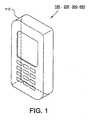
- the electronic device 100 with an electro-acoustic transducerincludes a housing 110 having a plurality of openings 114 penetrating between the inner surface 112 and the outer surface 118 thereof.
- An electro-acoustic transducer 180is disposed on the inner surface 112 of the housing 110.
- the electro-acoustic transducer 180includes an electret diaphragm 120 positioned on the inner surface 112 of the housing 110.
- the electret diaphragm 120includes a film body 122 and an electrode layer 124 formed on the lower surface of the film body 122.
- the film body 122is made of dielectric material and has static charges.
- the film body 122has a thickness of 7 to 25 ⁇ m and the electrode layer 124 has a thickness of 0.05 to 1 ⁇ m.
- a conductive plate 140 functioning as an electrodeis stacked on the upper surface of the film body 122 and has a plurality of openings 142 corresponding to the openings 114.
- the conductive plate 140has a thickness of 0.1 to 1 mm, and an aperture ratio of the openings 142 on the conductive plate 140 is greater than 20%.
- at least one spacer 150is disposed between the electret diaphragm 120 and the conductive plate 140 to keep a predetermined distance between the electret diaphragm 120 and the conductive plate 140.
- the spacer 150is spaced 5 to 20 mm apart from each other and has a height of 100 to 400 ⁇ m.
- the film body 122 originally without static charges carried thereonis required to be subjected to a polarizing process.
- a corona charging processcan be used to polarize the film body 122 to generate static charges therein and thereon after the electrode layer 124 is formed on the film body 122.
- the material suitable for the film body 122can be fluorinated ethylene propylene (FEP), Polytetrafluoroethene (PTFE), Polyvinylidene Fluoride (PVDF), silicon dioxide (SiO2) or other fluoride polymers.
- FEPfluorinated ethylene propylene
- PTFEPolytetrafluoroethene
- PVDFPolyvinylidene Fluoride
- SiO2silicon dioxide
- the edge of the electret diaphragm 120is required to be fixed to prevent the electret diaphragm 120 from movement.
- electro-acoustic transducer 180 of the present embodimentwork, electrical signals having the same phase and opposite phase with the original sound signal, i.e. differential signals have to be applied to the conductive plate 140 and electrode layer 124, respectively so that the electret diaphragm 120 is subject to the Coulomb forces from the conductive plate 140 and electrode layer 124 to bring about a push-pull effect.
- the push-pull effectwill cause the electret diaphragm 120 to vibrate in accordance with the electrical signals.
- the vibration of the electret diaphragm 120pushes the air to make sounds.
- the soundscan travel through the openings 114 to the outside of the housing 110 thereby a user can hear the sounds.
- the upper surface of the conductive plate 140is spaced a predetermined distance, said more that 1 mm apart from the elements above the conductive plate 140 to prevent the echo from degrading the performance of the electro-acoustic transducer 180.
- a sound absorbing layer 160made of, such as glass fiber, sponge or non-woven can be attached to the upper surface of the conductive plate 140 to absorb the sounds traveling through the openings 142.
- the sound absorbing layer 160has a thickness of 1 to 5 mm.
- At least one spacer 170 with a thickness of 30 to 50 ⁇ m and corresponding to the spacer 150is positioned between the electrode layer 124 and the inner surface 112 of the housing 110 to keep the electrode layer 124 from contact with the housing 110.
- the spacer 150can be made of adhesive material, such as double-sided tape to attach the conductive plate 140 and film body 122 together.
- the electronic device 200 with an electro-acoustic transducerhas all the elements of the electronic device 100, that is, the housing 110 and the electret diaphragm 120, conductive plate 140, spacers 150, 170 and sound absorbing layer 160 of the electro-acoustic transducer 180.
- the electro-acoustic transducer 280 of the electronic device 200further includes a conductive plate 240 functioning as an electrode that is stacked on the conductive plate 140 and has a plurality of openings 242 corresponding to the openings 142 of the conductive plate 140.
- the conductive plate 240has a thickness of 0.1 to 1 mm.
- An isolation layer 290 made of porous air-permeable membranehas a thickness of 20 to 200 ⁇ m and is disposed between the conductive plates 140 and 240.
- an electret diaphragm 220is positioned on the conductive plate 240 and includes a film body 222 and an electrode layer 224 formed on the upper surface of the film body 222, wherein the sound absorbing layer 160 is attached to the electrode layer 224.
- the film body 222is made of dielectric material and has static charges.
- the film body 222has a thickness of 7 to 25 ⁇ m and the electrode layer 224 has a thickness of 0.05 to 1 ⁇ m.
- At least one spacer 250 made of, such as adhesive material and corresponding to the spacer 150is disposed between the electret diaphragm 220 and the conductive plate 240 to keep a predetermined distance between the electret diaphragm 220 and the conductive plate 240.
- the spacer 250has a height of 100 to 400 ⁇ m.
- the film body 222 originally without static charges carried thereonis also required to be polarized in order to generate static charges therein and thereon.
- the material suitable for the film body 222can be FEP, PTFE, PVDF, silicon dioxide or other fluoride polymers.
- the edge of the electret diaphragm 220is also required to be fixed to prevent the electret diaphragm 220 from movement.
- a first electrical signal having the same phase with the original sound signalhave to be applied to the conductive plate 140 and the electrode layer 224 and a second electrical signal having opposite phase with the original sound signal is applied to the electrode layer 124 and the conductive plate 240.
- the electret diaphragms 120 and 220will be subject to the Coulomb forces from the conductive plates 140, 240 and electrode layers 124, 224 to vibrate and make sounds in accordance with the first and second electrical signals.
- the sounds made by the electret diaphragm 220can travel through the isolation layer 290 and openings 114 to the outside of the housing 110.
- the electro-acoustic transducer 280 with double electret diaphragmscan make double (3dB) sounds than the electro-acoustic transducer 180 with only a single electret diaphragm.
- the electronic device 300 with an electro-acoustic transducerincludes a housing 110 and an electro-acoustic transducer 380 disposed on the inner surface 112 of the housing 110.
- the electro-acoustic transducer 380includes a conductive plate 340 functioning as an electrode disposed on the inner surface 112 of the housing 110.
- the conductive plate 340has a plurality of openings 342 corresponding to the openings 114.
- An electret diaphragm 320is stacked on the conductive plate 340 and includes a film body 322 and an electrode layer 324 formed on the upper surface of the film body 322.
- the film body 322is made of dielectric material and has static charges.
- the film body 322has a thickness of 7 to 25 ⁇ m and the electrode layer 324 has a thickness of 0.05 to 1 ⁇ m
- at least one spacer 350 made of, such as adhesive materialis disposed between the electret diaphragm 320 and the conductive plate 340 to keep a predetermined distance between the electret diaphragm 320 and the conductive plate 340.
- the spacer 350is spaced 5 to 20 mm apart from each other and has a height of 100 to 400 ⁇ m.
- at least one spacer 370 made of, such as adhesive material and corresponding to the spacer 350is positioned between the conductive plate 340 and the inner surface 112 of the housing 110 to keep the conductive plate 340 from contact with the housing 110.
- the spacer 370has a thickness of 30 to 50 ⁇ m.
- a sound absorbing layer 360is attached to the electrode layer 324 to prevent the echo from degrading the performance of the electro-acoustic transducer 380.
- the film body 322 originally without static charges carried thereonis also required to be polarized in order to generate static charges therein and thereon.
- the material suitable for the film body 322can be FEP, PTFE, PVDF, silicon dioxide or other fluoride polymers.
- the edge of the electret diaphragm 320is also required to be fixed to prevent the electret diaphragm 320 from movement.
- an electrical signalhas to be applied to the conductive plate 340 and electrode layer 324 thereby the electret diaphragm 320 can vibrate to make sounds in accordance with the electrical signal.
- the electronic device 400 with an electro-acoustic transduceris substantially the same as the electronic device 300 of FIG. 4 , where identical reference numerals have been used when designating substantially identically elements that are common to the figures. Any further illustrations of the identical elements are omitted herein. The difference between them is in that the electro-acoustic transducer 480 of the electronic device 400 includes a conductive layer 440 coated on the inner surface 112 of the housing 110 to replace the conductive plate 340 and does not have the spacer 370.
- an electrical signalhas to be applied to the conductive layer 440 and electrode layer 324 thereby the electret diaphragm 320 can vibrate to make sounds in accordance with the electrical signal.
- the electro-acoustic transducers 180, 280, 380 and 480 of the electronic devices 100, 200, 300 and 400are disposed on the housing 110 and the housing 110 can be a front cover, side cover or back cover of the electronic devices 100, 200, 300 and 400. It will be appreciated that the electro-acoustic transducers 180, 280, 380 and 480 have to be electrically connected to other elements, such as circuit boards in the electronic devices 100, 200, 300 and 400 in order to work. Referring back to FIGS.
- the electrical terminals 119a and 119b disposed on the inner surface 112 of the back cover 110 of the electronic device 200are electrically connected to the conductive plate 240 and electrode layer 224 of the electro-acoustic transducer 280, respectively.
- the electrical terminals 116a and 116bare respectively brought into electrical contact with the electrical terminals 197a and 197b on the circuit boards 195 of the electronic devices 100, 200, 300 and 400, and the electrical terminals 119a and 119b (shown in FIG.
- the electrical signalscan be applied to the conductive plates 140, 240, 340, conductive layer 440 and electrode layers 124, 224, 324 thereby the electret diaphragms 120, 220, 320 can vibrate to make sounds in accordance with the electrical signals.
- the spacers of the electro-acoustic transducerscan be discrete spacers.
- the above discrete spacerscan be replaced with the sheets formed with a plurality of openings thereon.
- the electronic devices of the present inventioncan be portable electronic devices, such as mobile phones, personal digital assistants (PDAs) or laptop computers. Since the electro-acoustic transducers of the electronic devices according to the present invention have a greatly smaller thickness than the traditional dynamic loudspeakers, the available space inside the electronic device can be increased. In addition, the electro-acoustic transducers of the electronic devices according to the present invention can be mounted on the back covers. Therefore, the thickness of the electronic devices can be further reduced and the available space inside the electronic device can also be further increased.
- the electret surfaces of the electret diaphragms of the electro-acoustic transducers according to the first and second embodiments of the present inventionface the insides of the electronic devices, the electret surfaces therefore get rid of the contamination of the dust and moisture to avoid the malfunction of the electret diaphragms.
Landscapes
- Physics & Mathematics (AREA)
- Engineering & Computer Science (AREA)
- Acoustics & Sound (AREA)
- Signal Processing (AREA)
- Electrostatic, Electromagnetic, Magneto- Strictive, And Variable-Resistance Transducers (AREA)
- Audible-Bandwidth Dynamoelectric Transducers Other Than Pickups (AREA)
- Telephone Set Structure (AREA)
Description
- The invention relates to a portable electronic device with an electro-acoustic transducer, and more particularly, to a portable electronic device with an electret electro-acoustic transducer.
- Loudspeakers are a kind of device to make sound. The principle of making sound for the loudspeakers is to move the diaphragms thereof by electrical signals to push the air. Nowadays, the loudspeakers have been broadly used in electronic devices with the function of making sound, such as mobile phones, personal digital assistants (PDAs) and laptop computers.
- One of the common loudspeakers is so-called dynamic loudspeaker. The principle of making sound for the dynamic loudspeaker is to drive a current through the voice coil to produce a magnet field. This magnetic field causes the voice coil to react to the magnetic field from a permanent magnet fixed to the frame of the loudspeaker thereby moving the diaphragm attached with the voice coil. Although such dynamic loudspeaker can provide very good quality of sound, the loudspeaker has a considerable thickness because its sound chamber is large. When such dynamic loudspeakers are used in the above-mentioned portable electronic devices, the thickness of these electronic devices cannot be reduced.
EP 1722 596 A1 discloses an electret condenser microphone includes: a substrate in which an opening is formed; an electret condenser connected to one face of the substrate so as to close the opening and having an acoustic hole and a cavity; a drive circuit element connected to the one face of the substrate; and a case mounted over the substrate so as to cover the electret condenser and the drive circuit element . Electric contact is established at a joint part between the electret condenser and the substrate. The acoustic hole communicates with an external space through the opening. The cavity and an internal region of the case serve as a back air chamber for the electret condenser.US 20041170291 is directed to a mobile device with improved acoustic porting. The mobile device includes a housing that has at least one sound hole, a transducer for converting an electrical signal into an acoustical signal, and a grommet that engages the housing and the transducer to form an interior cavity. A passage acoustically couples the interior cavity with the interior of the housing. The transducer emits sound into the interior cavity. The sound travels from the interior cavity through the passage into the interior of the housing and then to the user's ear via the sound hole(s) in the housing. The passage may be any channel, tube, passageway, or pathway that allows an acoustical signal to travel from the interior cavity to the interior of the housing.; The transducer may also emit sound into the interior of the housing that mixes with the sound traveling from the interior cavity through the passage into the interior of the housing.- It is an object of the invention to provice a portable electronic device with an electret electro-acoustic transducer wherein the electret electro-acoustic transducer of the portable electronic devices has a greatly smaller thickness than the traditional dynamic loudspeakers.
- For this purpose, the portable electronic device of the invention comprises the features of claim 1.
- Preferred embodiments are characterized in the sub-claims.
- The portable electret electro-acoustic transducer of the portable electronic devices has a greatly smaller thickness than the traditional dynamic loudspeakers, and, therefore, the available space inside the electronic device can be increased.
- Embodiments of the invention will be more readily apparent from the following detailed description, which proceeds with reference to the accompanying drawings.
- FIG. 1
- is a perspective view of the electronic device of the present invention.
- FIG. 2a
- is a cross-sectional view of the electronic device with an electro-acoustic transducer, wherein the back cover is separated from the body of the electronic device.
- FIG. 2b
- is a cross-sectional view of the electronic device with an electro-acoustic transducer, wherein the back cover is attached to the body of the electronic device.
- FIG. 3a
- is a cross-sectional view of the electronic device with an electro-acoustic transducer, wherein the back cover is separated from the body of the electronic device.
- FIG. 3b
- is a cross-sectional view of the electronic device with an electro-acoustic transducer, wherein the back cover is attached to the body of the electronic device.
- FIG, 4a
- is a cross-sectional view of the electronic device with an electro-acoustic transducer, wherein the back cover is separated from the body of the electronic device.
- FIG. 4b
- is a cross-sectional view of the electronic device with an electro-acoustic transducer, wherein the back cover is attached to the body of the electronic device.
- FIG. 5a
- is a cross-sectional view of the electronic device with an electro-acoustic transducer according to an embodiment of the present invention, wherein the back cover is separated from the body of the electronic device.
- FIG. 5b
- is a cross-sectional view of the electronic device with an electro-acoustic transducer according to the embodiment of the present invention, wherein the back cover is attached to the body of the electronic device.
- Referring to
FIGS.1 ,2a and 2b , theelectronic device 100 with an electro-acoustic transducer includes ahousing 110 having a plurality ofopenings 114 penetrating between theinner surface 112 and theouter surface 118 thereof. An electro-acoustic transducer 180 is disposed on theinner surface 112 of thehousing 110. The electro-acoustic transducer 180 includes anelectret diaphragm 120 positioned on theinner surface 112 of thehousing 110. In addition, theelectret diaphragm 120 includes afilm body 122 and anelectrode layer 124 formed on the lower surface of thefilm body 122. Thefilm body 122 is made of dielectric material and has static charges. Thefilm body 122 has a thickness of 7 to 25 µm and theelectrode layer 124 has a thickness of 0.05 to 1 µm. Aconductive plate 140 functioning as an electrode is stacked on the upper surface of thefilm body 122 and has a plurality ofopenings 142 corresponding to theopenings 114. Theconductive plate 140 has a thickness of 0.1 to 1 mm, and an aperture ratio of theopenings 142 on theconductive plate 140 is greater than 20%. Furthermore, at least onespacer 150 is disposed between theelectret diaphragm 120 and theconductive plate 140 to keep a predetermined distance between theelectret diaphragm 120 and theconductive plate 140. Thespacer 150 is spaced 5 to 20 mm apart from each other and has a height of 100 to 400 µm. - In order to make the
film body 122 carry static charges, thefilm body 122 originally without static charges carried thereon is required to be subjected to a polarizing process. For example, a corona charging process can be used to polarize thefilm body 122 to generate static charges therein and thereon after theelectrode layer 124 is formed on thefilm body 122. The material suitable for thefilm body 122 can be fluorinated ethylene propylene (FEP), Polytetrafluoroethene (PTFE), Polyvinylidene Fluoride (PVDF), silicon dioxide (SiO2) or other fluoride polymers. Furthermore, the edge of theelectret diaphragm 120 is required to be fixed to prevent theelectret diaphragm 120 from movement. To have the electro-acoustic transducer 180 of the present embodiment work, electrical signals having the same phase and opposite phase with the original sound signal, i.e. differential signals have to be applied to theconductive plate 140 andelectrode layer 124, respectively so that theelectret diaphragm 120 is subject to the Coulomb forces from theconductive plate 140 andelectrode layer 124 to bring about a push-pull effect. The push-pull effect will cause theelectret diaphragm 120 to vibrate in accordance with the electrical signals. The vibration of theelectret diaphragm 120 pushes the air to make sounds. The sounds can travel through theopenings 114 to the outside of thehousing 110 thereby a user can hear the sounds. - In addition, since the sounds made by the
electret diaphragm 120 can also travel through theopenings 142 of theconductive plate 140 and be bounced back by the elements above theconductive plate 140, the upper surface of theconductive plate 140 is spaced a predetermined distance, said more that 1 mm apart from the elements above theconductive plate 140 to prevent the echo from degrading the performance of the electro-acoustic transducer 180. Alternatively, asound absorbing layer 160 made of, such as glass fiber, sponge or non-woven can be attached to the upper surface of theconductive plate 140 to absorb the sounds traveling through theopenings 142. Thesound absorbing layer 160 has a thickness of 1 to 5 mm. Moreover, at least onespacer 170 with a thickness of 30 to 50 µm and corresponding to thespacer 150 is positioned between theelectrode layer 124 and theinner surface 112 of thehousing 110 to keep theelectrode layer 124 from contact with thehousing 110. Furthermore, thespacer 150 can be made of adhesive material, such as double-sided tape to attach theconductive plate 140 andfilm body 122 together. - Referring to
FIGS. 1 ,3a and 3b , theelectronic device 200 with an electro-acoustic transducer has all the elements of theelectronic device 100, that is, thehousing 110 and theelectret diaphragm 120,conductive plate 140,spacers absorbing layer 160 of the electro-acoustic transducer 180. In addition to the above elements, the electro-acoustic transducer 280 of theelectronic device 200 further includes aconductive plate 240 functioning as an electrode that is stacked on theconductive plate 140 and has a plurality ofopenings 242 corresponding to theopenings 142 of theconductive plate 140. Theconductive plate 240 has a thickness of 0.1 to 1 mm. Anisolation layer 290 made of porous air-permeable membrane has a thickness of 20 to 200 µm and is disposed between theconductive plates electret diaphragm 220 is positioned on theconductive plate 240 and includes afilm body 222 and anelectrode layer 224 formed on the upper surface of thefilm body 222, wherein thesound absorbing layer 160 is attached to theelectrode layer 224. Thefilm body 222 is made of dielectric material and has static charges. Thefilm body 222 has a thickness of 7 to 25 µm and theelectrode layer 224 has a thickness of 0.05 to 1 µm. Furthermore, at least onespacer 250 made of, such as adhesive material and corresponding to thespacer 150 is disposed between theelectret diaphragm 220 and theconductive plate 240 to keep a predetermined distance between theelectret diaphragm 220 and theconductive plate 240. Thespacer 250 has a height of 100 to 400 µm. - Similarly, the
film body 222 originally without static charges carried thereon is also required to be polarized in order to generate static charges therein and thereon. The material suitable for thefilm body 222 can be FEP, PTFE, PVDF, silicon dioxide or other fluoride polymers. Furthermore, the edge of theelectret diaphragm 220 is also required to be fixed to prevent theelectret diaphragm 220 from movement. To have the electro-acoustic transducer 280 of the present embodiment work, a first electrical signal having the same phase with the original sound signal have to be applied to theconductive plate 140 and theelectrode layer 224 and a second electrical signal having opposite phase with the original sound signal is applied to theelectrode layer 124 and theconductive plate 240. In this manner, theelectret diaphragms conductive plates electrode layers electret diaphragm 220 can travel through theisolation layer 290 andopenings 114 to the outside of thehousing 110. The electro-acoustic transducer 280 with double electret diaphragms can make double (3dB) sounds than the electro-acoustic transducer 180 with only a single electret diaphragm. - Referring to
FIGS. 1 ,4a and 4b , theelectronic device 300 with an electro-acoustic transducer includes ahousing 110 and an electro-acoustic transducer 380 disposed on theinner surface 112 of thehousing 110. The electro-acoustic transducer 380 includes aconductive plate 340 functioning as an electrode disposed on theinner surface 112 of thehousing 110. Theconductive plate 340 has a plurality ofopenings 342 corresponding to theopenings 114. Anelectret diaphragm 320 is stacked on theconductive plate 340 and includes afilm body 322 and anelectrode layer 324 formed on the upper surface of thefilm body 322. Thefilm body 322 is made of dielectric material and has static charges. Thefilm body 322 has a thickness of 7 to 25 µm and theelectrode layer 324 has a thickness of 0.05 to 1 µm, In addition, at least onespacer 350 made of, such as adhesive material is disposed between theelectret diaphragm 320 and theconductive plate 340 to keep a predetermined distance between theelectret diaphragm 320 and theconductive plate 340. Thespacer 350 is spaced 5 to 20 mm apart from each other and has a height of 100 to 400 µm. Moreover, at least onespacer 370 made of, such as adhesive material and corresponding to thespacer 350 is positioned between theconductive plate 340 and theinner surface 112 of thehousing 110 to keep theconductive plate 340 from contact with thehousing 110. Thespacer 370 has a thickness of 30 to 50 µm. Furthermore, asound absorbing layer 360 is attached to theelectrode layer 324 to prevent the echo from degrading the performance of the electro-acoustic transducer 380. - Similarly, the
film body 322 originally without static charges carried thereon is also required to be polarized in order to generate static charges therein and thereon. The material suitable for thefilm body 322 can be FEP, PTFE, PVDF, silicon dioxide or other fluoride polymers. Furthermore, the edge of theelectret diaphragm 320 is also required to be fixed to prevent theelectret diaphragm 320 from movement. To have the electro-acoustic transducer 380 of the present embodiment work, an electrical signal has to be applied to theconductive plate 340 andelectrode layer 324 thereby theelectret diaphragm 320 can vibrate to make sounds in accordance with the electrical signal. - Referring to
FIGS. 1 ,5a and 5b , theelectronic device 400 with an electro-acoustic transducer according to an embodiment of the present invention is substantially the same as theelectronic device 300 ofFIG. 4 , where identical reference numerals have been used when designating substantially identically elements that are common to the figures. Any further illustrations of the identical elements are omitted herein. The difference between them is in that the electro-acoustic transducer 480 of theelectronic device 400 includes aconductive layer 440 coated on theinner surface 112 of thehousing 110 to replace theconductive plate 340 and does not have thespacer 370. Similarly, to have the electro-acoustic transducer 480 of the present embodiment work, an electrical signal has to be applied to theconductive layer 440 andelectrode layer 324 thereby theelectret diaphragm 320 can vibrate to make sounds in accordance with the electrical signal. - The electro-
acoustic transducers electronic devices housing 110 and thehousing 110 can be a front cover, side cover or back cover of theelectronic devices acoustic transducers electronic devices FIGS. 2a, 2b ,3a, 3b ,4a, 4b ,5a and 5b , when the electro-acoustic transducers electrical terminals 116a are disposed on theinner surfaces 112 of the back covers 110 to electrically connect to theconductive plates conductive layer 440, and theelectrical terminals 116b disposed on theinner surfaces 112 of the back covers 110 are electrically connected to the electrode layers 124 and 324. In addition, theelectrical terminals inner surface 112 of theback cover 110 of theelectronic device 200 are electrically connected to theconductive plate 240 andelectrode layer 224 of the electro-acoustic transducer 280, respectively. As shown inFIGS. 2b ,3b ,4b and5b , when theback cover 110 are attached to the body of theelectronic devices electrical terminals electrical terminals circuit boards 195 of theelectronic devices electrical terminals FIG. 3b ) are respectively brought into electrical contact with theelectrical terminals circuit board 195 of theelectronic device 200. In this way, the electrical signals can be applied to theconductive plates conductive layer 440 andelectrode layers electret diaphragms - According to the present invention, the spacers of the electro-acoustic transducers can be discrete spacers. However, it should be understood that the above discrete spacers can be replaced with the sheets formed with a plurality of openings thereon.
- The electronic devices of the present invention can be portable electronic devices, such as mobile phones, personal digital assistants (PDAs) or laptop computers. Since the electro-acoustic transducers of the electronic devices according to the present invention have a greatly smaller thickness than the traditional dynamic loudspeakers, the available space inside the electronic device can be increased. In addition, the electro-acoustic transducers of the electronic devices according to the present invention can be mounted on the back covers. Therefore, the thickness of the electronic devices can be further reduced and the available space inside the electronic device can also be further increased. Moreover, since the electret surfaces of the electret diaphragms of the electro-acoustic transducers according to the first and second embodiments of the present invention face the insides of the electronic devices, the electret surfaces therefore get rid of the contamination of the dust and moisture to avoid the malfunction of the electret diaphragms.
- Although a preferred embodiment of the invention has been disclosed for illustrative purposes, those skilled in the art will appreciate that various modifications, additions and substitutions are possible, without departing from the scope of the invention as disclosed in the accompanying claims.
Claims (4)
- A portable electronic device, which is a mobile phone, a personal digital assistant (PDA) or a laptop computer, comprising:a housing (110) having an inner surface (112), an outer surface (118) and a plurality of openings (114) penetrating between the inner surface (112) and the outer surface (118) thereof;a circuit board (195); andan electro-acoustic transducer (480) disposed on the inner surface (112) of the housing (110) and electrically connected to the circuit board (195), comprising:a conductive layer (440) coated on the inner surface (112) of the housing (110);an electret diaphragm (320) adapted to make sounds in accordance with an electrical signal, the electret diaphragm (320) being stacked on the conductive layer (440) and having a film body (322) and an electrode layer (324), wherein the film body (322) has static charges and the electrode layer (324) is formed on the film body (322); andat least one spacer (350) disposed between the electret diaphragm (320) and the conductive layer (440) to keep a predetermined distance between the electret diaphragm (320) and the conductive layer (440),the device further comprising:a first electrical terminal (116a) and a second electrical terminal (116b) disposed on the inner surface (112) of the housing (110) for electrically connecting the electrical signal to the electrode layer (324) of the electret diaphragm (320) and the conductive layer (440), respectively;a third electrical terminal (197a) and a fourth electrical terminal (197b) on the circuit board (195), wherein the first electrical terminal (116a) and the second electrical terminal (116b) are respectively electrically coupled with the third electrical terminal (197a) and the fourth electrical terminal (197b) whereby the electrical signal is applied to the electrode layer (324) of the electret diaphragm (320) and the conductive layer (440).
- The portable electronic device as claimed in claim 1, wherein the electro-acoustic transducer (480) further comprises a sound absorbing layer (360) attached to the electrode layer (324) of the electret diaphragm (320).
- The portable electronic device as claimed in claim 1, wherein the at least one spacer (350) is made of adhesive material.
- The portable electronic device as claimed in claim 1, wherein the electrode layer (324) of the electret diaphragm (320) and the conductive layer (440) are electrically connected to the electrical signal.
Applications Claiming Priority (2)
| Application Number | Priority Date | Filing Date | Title |
|---|---|---|---|
| TW097141921ATWI454156B (en) | 2008-10-31 | 2008-10-31 | Electronic device with electret electro-acoustic transducer |
| EP09169282.2AEP2182737B1 (en) | 2008-10-31 | 2009-09-02 | Electronic device with electret electro-acoustic transducer |
Related Parent Applications (3)
| Application Number | Title | Priority Date | Filing Date |
|---|---|---|---|
| EP09169282.2Division | 2009-09-02 | ||
| EP09169282.2ADivisionEP2182737B1 (en) | 2008-10-31 | 2009-09-02 | Electronic device with electret electro-acoustic transducer |
| EP09169282.2ADivision-IntoEP2182737B1 (en) | 2008-10-31 | 2009-09-02 | Electronic device with electret electro-acoustic transducer |
Publications (3)
| Publication Number | Publication Date |
|---|---|
| EP2369855A2 EP2369855A2 (en) | 2011-09-28 |
| EP2369855A3 EP2369855A3 (en) | 2012-04-04 |
| EP2369855B1true EP2369855B1 (en) | 2014-05-07 |
Family
ID=41137441
Family Applications (2)
| Application Number | Title | Priority Date | Filing Date |
|---|---|---|---|
| EP09169282.2ANot-in-forceEP2182737B1 (en) | 2008-10-31 | 2009-09-02 | Electronic device with electret electro-acoustic transducer |
| EP11162045.6ANot-in-forceEP2369855B1 (en) | 2008-10-31 | 2009-09-02 | Electronic device with electret electro-acoustic transducer |
Family Applications Before (1)
| Application Number | Title | Priority Date | Filing Date |
|---|---|---|---|
| EP09169282.2ANot-in-forceEP2182737B1 (en) | 2008-10-31 | 2009-09-02 | Electronic device with electret electro-acoustic transducer |
Country Status (3)
| Country | Link |
|---|---|
| EP (2) | EP2182737B1 (en) |
| JP (1) | JP5054749B2 (en) |
| TW (1) | TWI454156B (en) |
Families Citing this family (5)
| Publication number | Priority date | Publication date | Assignee | Title |
|---|---|---|---|---|
| US8472650B2 (en) | 2008-10-15 | 2013-06-25 | Htc Corporation | Electro-acoustic transducer |
| US8243965B2 (en)* | 2008-10-15 | 2012-08-14 | Htc Corporation | Electro-acoustic transducer |
| TWI439139B (en) | 2010-06-17 | 2014-05-21 | Htc Corp | Capacitive electro-acoustic transduction system and capacitive electro-acoustic transducer thereof |
| DE102013213891A1 (en)* | 2013-05-21 | 2014-11-27 | Siemens Medical Instruments Pte. Ltd. | microphone array |
| US11228844B2 (en) | 2017-05-18 | 2022-01-18 | The Johns Hopkins University | Push-pull electret transducer with controlled restoring force for low frequency microphones and energy harvesting |
Citations (1)
| Publication number | Priority date | Publication date | Assignee | Title |
|---|---|---|---|---|
| US20040170291A1 (en)* | 2003-02-28 | 2004-09-02 | Eaton W. Chris | Mobile device with improved acoustic porting |
Family Cites Families (24)
| Publication number | Priority date | Publication date | Assignee | Title |
|---|---|---|---|---|
| US3084229A (en) | 1960-03-11 | 1963-04-02 | Ampex | Electrostatic earphone |
| US3935397A (en)* | 1974-01-28 | 1976-01-27 | Electronic Industries, Inc. | Electrostatic loudspeaker element |
| JPS5127318A (en)* | 1974-08-31 | 1976-03-06 | Tokyo Shibaura Electric Co | SEIDENGATADENKIONKYOHENKANKI |
| JPS536673U (en)* | 1976-07-03 | 1978-01-20 | ||
| US4160882A (en) | 1978-03-13 | 1979-07-10 | Driver Michael L | Double diaphragm electrostatic transducer each diaphragm comprising two plastic sheets having different charge carrying characteristics |
| JP2000508860A (en)* | 1996-04-18 | 2000-07-11 | カリフォルニア インスティチュート オブ テクノロジー | Thin film electret microphone |
| JP3322144B2 (en)* | 1996-12-20 | 2002-09-09 | 三菱電機株式会社 | Electrostatic transparent speaker |
| WO2000027166A2 (en)* | 1998-11-02 | 2000-05-11 | Sarnoff Corporation | Transducer concepts for hearing aids and other devices |
| WO2000070630A2 (en)* | 1999-05-19 | 2000-11-23 | California Institute Of Technology | High performance mems thin-film teflon® electret microphone |
| JP2002345084A (en)* | 2001-05-16 | 2002-11-29 | Citizen Electronics Co Ltd | Speaker |
| JP2003102097A (en)* | 2001-09-25 | 2003-04-04 | Nippon Hoso Kyokai <Nhk> | Sound processing device |
| JP2004166262A (en)* | 2002-10-23 | 2004-06-10 | Matsushita Electric Ind Co Ltd | Electroacoustic transducer and method of manufacturing the same |
| DE10300063A1 (en) | 2003-01-03 | 2004-07-22 | W.L. Gore & Associates Gmbh | Membrane for acoustic transducers |
| US7089635B2 (en)* | 2003-02-25 | 2006-08-15 | Palo Alto Research Center, Incorporated | Methods to make piezoelectric ceramic thick film arrays and elements |
| US7382048B2 (en)* | 2003-02-28 | 2008-06-03 | Knowles Electronics, Llc | Acoustic transducer module |
| JP3979334B2 (en)* | 2003-04-21 | 2007-09-19 | 株式会社村田製作所 | Piezoelectric electroacoustic transducer |
| KR20060127166A (en)* | 2004-03-09 | 2006-12-11 | 마츠시타 덴끼 산교 가부시키가이샤 | Electret condenser microphone |
| US7352873B2 (en)* | 2004-04-27 | 2008-04-01 | Hosiden Corporation | Electret-condenser microphone |
| US7329933B2 (en)* | 2004-10-29 | 2008-02-12 | Silicon Matrix Pte. Ltd. | Silicon microphone with softly constrained diaphragm |
| JP4822517B2 (en)* | 2005-05-24 | 2011-11-24 | パナソニック株式会社 | Speaker device |
| JP4770605B2 (en) | 2006-06-26 | 2011-09-14 | ヤマハ株式会社 | Balanced output microphone and method of manufacturing balanced output microphone |
| US20080123876A1 (en)* | 2006-10-16 | 2008-05-29 | Yamaha Corporation | Electrostatic pressure transducer and manufacturing method therefor |
| TWI330500B (en)* | 2007-09-04 | 2010-09-11 | Ind Tech Res Inst | Speaker structure |
| US8081784B2 (en)* | 2007-09-04 | 2011-12-20 | Industrial Technology Research Institute | Electrostatic electroacoustic transducers |
- 2008
- 2008-10-31TWTW097141921Apatent/TWI454156B/ennot_activeIP Right Cessation
- 2009
- 2009-09-02EPEP09169282.2Apatent/EP2182737B1/ennot_activeNot-in-force
- 2009-09-02EPEP11162045.6Apatent/EP2369855B1/ennot_activeNot-in-force
- 2009-10-20JPJP2009241546Apatent/JP5054749B2/ennot_activeExpired - Fee Related
Patent Citations (1)
| Publication number | Priority date | Publication date | Assignee | Title |
|---|---|---|---|---|
| US20040170291A1 (en)* | 2003-02-28 | 2004-09-02 | Eaton W. Chris | Mobile device with improved acoustic porting |
Also Published As
| Publication number | Publication date |
|---|---|
| JP5054749B2 (en) | 2012-10-24 |
| EP2369855A3 (en) | 2012-04-04 |
| TW201018252A (en) | 2010-05-01 |
| EP2369855A2 (en) | 2011-09-28 |
| EP2182737A1 (en) | 2010-05-05 |
| JP2010109979A (en) | 2010-05-13 |
| TWI454156B (en) | 2014-09-21 |
| EP2182737B1 (en) | 2014-03-05 |
Similar Documents
| Publication | Publication Date | Title |
|---|---|---|
| US8411882B2 (en) | Electronic device with electret electro-acoustic transducer | |
| TW440446B (en) | Hearing aid with large diaphragm microphone element including a printed circuit board | |
| JP5759641B1 (en) | Electroacoustic transducer and electronic device | |
| US8649545B2 (en) | Microphone unit | |
| JP3971763B2 (en) | Electret condenser microphone | |
| JP5099605B2 (en) | Electronic device and electroacoustic transducer | |
| CN101375628A (en) | Electronic device and acoustic playback method | |
| US10531203B2 (en) | Acoustic apparatus and associated methods | |
| JPWO2006062120A1 (en) | Microphone device | |
| US20150189443A1 (en) | Silicon Condenser Microphone | |
| EP2369855B1 (en) | Electronic device with electret electro-acoustic transducer | |
| WO2017082560A1 (en) | Acoustic output device | |
| CN1757261A (en) | Electret condenser microphone | |
| CN217363312U (en) | MEMS microphone | |
| CN101940002A (en) | Microphone unit | |
| US8369545B2 (en) | Flexible luminescent electro-acoustic transducer and electronic device using the same | |
| JP5152906B2 (en) | Omnidirectional condenser microphone unit and omnidirectional condenser microphone | |
| JP5097603B2 (en) | Microphone unit | |
| CN101742388B (en) | Electronic device with electret electroacoustic transducer | |
| KR100499356B1 (en) | Directivity condenser microphone | |
| CN101778326B (en) | Flexible cold photoacoustic actuator and electronic device using the electroacoustic actuator | |
| JP5269569B2 (en) | Condenser microphone unit and condenser microphone | |
| KR100812688B1 (en) | Condenser Microphone | |
| JP3967676B2 (en) | Condenser microphone unit | |
| WO2024138923A1 (en) | Mems microphone |
Legal Events
| Date | Code | Title | Description |
|---|---|---|---|
| PUAI | Public reference made under article 153(3) epc to a published international application that has entered the european phase | Free format text:ORIGINAL CODE: 0009012 | |
| 17P | Request for examination filed | Effective date:20110426 | |
| AC | Divisional application: reference to earlier application | Ref document number:2182737 Country of ref document:EP Kind code of ref document:P | |
| AK | Designated contracting states | Kind code of ref document:A2 Designated state(s):AT BE BG CH CY CZ DE DK EE ES FI FR GB GR HR HU IE IS IT LI LT LU LV MC MK MT NL NO PL PT RO SE SI SK SM TR | |
| PUAL | Search report despatched | Free format text:ORIGINAL CODE: 0009013 | |
| AK | Designated contracting states | Kind code of ref document:A3 Designated state(s):AT BE BG CH CY CZ DE DK EE ES FI FR GB GR HR HU IE IS IT LI LT LU LV MC MK MT NL NO PL PT RO SE SI SK SM TR | |
| RIC1 | Information provided on ipc code assigned before grant | Ipc:H04R 19/01 20060101AFI20120224BHEP | |
| GRAP | Despatch of communication of intention to grant a patent | Free format text:ORIGINAL CODE: EPIDOSNIGR1 | |
| INTG | Intention to grant announced | Effective date:20131211 | |
| GRAS | Grant fee paid | Free format text:ORIGINAL CODE: EPIDOSNIGR3 | |
| GRAA | (expected) grant | Free format text:ORIGINAL CODE: 0009210 | |
| AC | Divisional application: reference to earlier application | Ref document number:2182737 Country of ref document:EP Kind code of ref document:P | |
| AK | Designated contracting states | Kind code of ref document:B1 Designated state(s):AT BE BG CH CY CZ DE DK EE ES FI FR GB GR HR HU IE IS IT LI LT LU LV MC MK MT NL NO PL PT RO SE SI SK SM TR | |
| REG | Reference to a national code | Ref country code:GB Ref legal event code:FG4D | |
| REG | Reference to a national code | Ref country code:AT Ref legal event code:REF Ref document number:667457 Country of ref document:AT Kind code of ref document:T Effective date:20140515 | |
| REG | Reference to a national code | Ref country code:IE Ref legal event code:FG4D | |
| REG | Reference to a national code | Ref country code:DE Ref legal event code:R096 Ref document number:602009024039 Country of ref document:DE Effective date:20140618 | |
| REG | Reference to a national code | Ref country code:NL Ref legal event code:T3 | |
| REG | Reference to a national code | Ref country code:AT Ref legal event code:MK05 Ref document number:667457 Country of ref document:AT Kind code of ref document:T Effective date:20140507 | |
| REG | Reference to a national code | Ref country code:LT Ref legal event code:MG4D | |
| PG25 | Lapsed in a contracting state [announced via postgrant information from national office to epo] | Ref country code:CY Free format text:LAPSE BECAUSE OF FAILURE TO SUBMIT A TRANSLATION OF THE DESCRIPTION OR TO PAY THE FEE WITHIN THE PRESCRIBED TIME-LIMIT Effective date:20140507 Ref country code:GR Free format text:LAPSE BECAUSE OF FAILURE TO SUBMIT A TRANSLATION OF THE DESCRIPTION OR TO PAY THE FEE WITHIN THE PRESCRIBED TIME-LIMIT Effective date:20140808 Ref country code:NO Free format text:LAPSE BECAUSE OF FAILURE TO SUBMIT A TRANSLATION OF THE DESCRIPTION OR TO PAY THE FEE WITHIN THE PRESCRIBED TIME-LIMIT Effective date:20140807 Ref country code:IS Free format text:LAPSE BECAUSE OF FAILURE TO SUBMIT A TRANSLATION OF THE DESCRIPTION OR TO PAY THE FEE WITHIN THE PRESCRIBED TIME-LIMIT Effective date:20140907 Ref country code:LT Free format text:LAPSE BECAUSE OF FAILURE TO SUBMIT A TRANSLATION OF THE DESCRIPTION OR TO PAY THE FEE WITHIN THE PRESCRIBED TIME-LIMIT Effective date:20140507 Ref country code:FI Free format text:LAPSE BECAUSE OF FAILURE TO SUBMIT A TRANSLATION OF THE DESCRIPTION OR TO PAY THE FEE WITHIN THE PRESCRIBED TIME-LIMIT Effective date:20140507 | |
| PG25 | Lapsed in a contracting state [announced via postgrant information from national office to epo] | Ref country code:LV Free format text:LAPSE BECAUSE OF FAILURE TO SUBMIT A TRANSLATION OF THE DESCRIPTION OR TO PAY THE FEE WITHIN THE PRESCRIBED TIME-LIMIT Effective date:20140507 Ref country code:AT Free format text:LAPSE BECAUSE OF FAILURE TO SUBMIT A TRANSLATION OF THE DESCRIPTION OR TO PAY THE FEE WITHIN THE PRESCRIBED TIME-LIMIT Effective date:20140507 Ref country code:PL Free format text:LAPSE BECAUSE OF FAILURE TO SUBMIT A TRANSLATION OF THE DESCRIPTION OR TO PAY THE FEE WITHIN THE PRESCRIBED TIME-LIMIT Effective date:20140507 Ref country code:HR Free format text:LAPSE BECAUSE OF FAILURE TO SUBMIT A TRANSLATION OF THE DESCRIPTION OR TO PAY THE FEE WITHIN THE PRESCRIBED TIME-LIMIT Effective date:20140507 Ref country code:ES Free format text:LAPSE BECAUSE OF FAILURE TO SUBMIT A TRANSLATION OF THE DESCRIPTION OR TO PAY THE FEE WITHIN THE PRESCRIBED TIME-LIMIT Effective date:20140507 Ref country code:SE Free format text:LAPSE BECAUSE OF FAILURE TO SUBMIT A TRANSLATION OF THE DESCRIPTION OR TO PAY THE FEE WITHIN THE PRESCRIBED TIME-LIMIT Effective date:20140507 | |
| PG25 | Lapsed in a contracting state [announced via postgrant information from national office to epo] | Ref country code:PT Free format text:LAPSE BECAUSE OF FAILURE TO SUBMIT A TRANSLATION OF THE DESCRIPTION OR TO PAY THE FEE WITHIN THE PRESCRIBED TIME-LIMIT Effective date:20140908 | |
| PG25 | Lapsed in a contracting state [announced via postgrant information from national office to epo] | Ref country code:CZ Free format text:LAPSE BECAUSE OF FAILURE TO SUBMIT A TRANSLATION OF THE DESCRIPTION OR TO PAY THE FEE WITHIN THE PRESCRIBED TIME-LIMIT Effective date:20140507 Ref country code:BE Free format text:LAPSE BECAUSE OF FAILURE TO SUBMIT A TRANSLATION OF THE DESCRIPTION OR TO PAY THE FEE WITHIN THE PRESCRIBED TIME-LIMIT Effective date:20140507 Ref country code:EE Free format text:LAPSE BECAUSE OF FAILURE TO SUBMIT A TRANSLATION OF THE DESCRIPTION OR TO PAY THE FEE WITHIN THE PRESCRIBED TIME-LIMIT Effective date:20140507 Ref country code:DK Free format text:LAPSE BECAUSE OF FAILURE TO SUBMIT A TRANSLATION OF THE DESCRIPTION OR TO PAY THE FEE WITHIN THE PRESCRIBED TIME-LIMIT Effective date:20140507 Ref country code:RO Free format text:LAPSE BECAUSE OF FAILURE TO SUBMIT A TRANSLATION OF THE DESCRIPTION OR TO PAY THE FEE WITHIN THE PRESCRIBED TIME-LIMIT Effective date:20140507 Ref country code:SK Free format text:LAPSE BECAUSE OF FAILURE TO SUBMIT A TRANSLATION OF THE DESCRIPTION OR TO PAY THE FEE WITHIN THE PRESCRIBED TIME-LIMIT Effective date:20140507 | |
| REG | Reference to a national code | Ref country code:DE Ref legal event code:R097 Ref document number:602009024039 Country of ref document:DE | |
| REG | Reference to a national code | Ref country code:CH Ref legal event code:PCOW Free format text:NEW ADDRESS: NO. 23, XINGHUA ROAD TAOYUAN DISTRICT, TAOYUAN CITY 330 (TW) | |
| PLBE | No opposition filed within time limit | Free format text:ORIGINAL CODE: 0009261 | |
| STAA | Information on the status of an ep patent application or granted ep patent | Free format text:STATUS: NO OPPOSITION FILED WITHIN TIME LIMIT | |
| RAP2 | Party data changed (patent owner data changed or rights of a patent transferred) | Owner name:HTC CORPORATION | |
| 26N | No opposition filed | Effective date:20150210 | |
| PG25 | Lapsed in a contracting state [announced via postgrant information from national office to epo] | Ref country code:LU Free format text:LAPSE BECAUSE OF FAILURE TO SUBMIT A TRANSLATION OF THE DESCRIPTION OR TO PAY THE FEE WITHIN THE PRESCRIBED TIME-LIMIT Effective date:20140902 Ref country code:MC Free format text:LAPSE BECAUSE OF FAILURE TO SUBMIT A TRANSLATION OF THE DESCRIPTION OR TO PAY THE FEE WITHIN THE PRESCRIBED TIME-LIMIT Effective date:20140507 Ref country code:IT Free format text:LAPSE BECAUSE OF FAILURE TO SUBMIT A TRANSLATION OF THE DESCRIPTION OR TO PAY THE FEE WITHIN THE PRESCRIBED TIME-LIMIT Effective date:20140507 | |
| REG | Reference to a national code | Ref country code:CH Ref legal event code:PL | |
| REG | Reference to a national code | Ref country code:DE Ref legal event code:R097 Ref document number:602009024039 Country of ref document:DE Effective date:20150210 | |
| REG | Reference to a national code | Ref country code:IE Ref legal event code:MM4A | |
| PG25 | Lapsed in a contracting state [announced via postgrant information from national office to epo] | Ref country code:SI Free format text:LAPSE BECAUSE OF FAILURE TO SUBMIT A TRANSLATION OF THE DESCRIPTION OR TO PAY THE FEE WITHIN THE PRESCRIBED TIME-LIMIT Effective date:20140507 Ref country code:LI Free format text:LAPSE BECAUSE OF NON-PAYMENT OF DUE FEES Effective date:20140930 Ref country code:CH Free format text:LAPSE BECAUSE OF NON-PAYMENT OF DUE FEES Effective date:20140930 | |
| PG25 | Lapsed in a contracting state [announced via postgrant information from national office to epo] | Ref country code:IE Free format text:LAPSE BECAUSE OF NON-PAYMENT OF DUE FEES Effective date:20140902 | |
| PG25 | Lapsed in a contracting state [announced via postgrant information from national office to epo] | Ref country code:SM Free format text:LAPSE BECAUSE OF FAILURE TO SUBMIT A TRANSLATION OF THE DESCRIPTION OR TO PAY THE FEE WITHIN THE PRESCRIBED TIME-LIMIT Effective date:20140507 | |
| PG25 | Lapsed in a contracting state [announced via postgrant information from national office to epo] | Ref country code:BG Free format text:LAPSE BECAUSE OF FAILURE TO SUBMIT A TRANSLATION OF THE DESCRIPTION OR TO PAY THE FEE WITHIN THE PRESCRIBED TIME-LIMIT Effective date:20140507 Ref country code:MT Free format text:LAPSE BECAUSE OF FAILURE TO SUBMIT A TRANSLATION OF THE DESCRIPTION OR TO PAY THE FEE WITHIN THE PRESCRIBED TIME-LIMIT Effective date:20140507 | |
| PG25 | Lapsed in a contracting state [announced via postgrant information from national office to epo] | Ref country code:TR Free format text:LAPSE BECAUSE OF FAILURE TO SUBMIT A TRANSLATION OF THE DESCRIPTION OR TO PAY THE FEE WITHIN THE PRESCRIBED TIME-LIMIT Effective date:20140507 Ref country code:HU Free format text:LAPSE BECAUSE OF FAILURE TO SUBMIT A TRANSLATION OF THE DESCRIPTION OR TO PAY THE FEE WITHIN THE PRESCRIBED TIME-LIMIT; INVALID AB INITIO Effective date:20090902 | |
| REG | Reference to a national code | Ref country code:FR Ref legal event code:PLFP Year of fee payment:8 | |
| REG | Reference to a national code | Ref country code:FR Ref legal event code:PLFP Year of fee payment:9 | |
| PG25 | Lapsed in a contracting state [announced via postgrant information from national office to epo] | Ref country code:MK Free format text:LAPSE BECAUSE OF FAILURE TO SUBMIT A TRANSLATION OF THE DESCRIPTION OR TO PAY THE FEE WITHIN THE PRESCRIBED TIME-LIMIT Effective date:20140507 | |
| REG | Reference to a national code | Ref country code:FR Ref legal event code:PLFP Year of fee payment:10 | |
| PGFP | Annual fee paid to national office [announced via postgrant information from national office to epo] | Ref country code:FR Payment date:20180712 Year of fee payment:10 Ref country code:NL Payment date:20180815 Year of fee payment:10 Ref country code:DE Payment date:20180821 Year of fee payment:10 | |
| PGFP | Annual fee paid to national office [announced via postgrant information from national office to epo] | Ref country code:GB Payment date:20180829 Year of fee payment:10 | |
| REG | Reference to a national code | Ref country code:DE Ref legal event code:R119 Ref document number:602009024039 Country of ref document:DE | |
| REG | Reference to a national code | Ref country code:NL Ref legal event code:MM Effective date:20191001 | |
| PG25 | Lapsed in a contracting state [announced via postgrant information from national office to epo] | Ref country code:DE Free format text:LAPSE BECAUSE OF NON-PAYMENT OF DUE FEES Effective date:20200401 Ref country code:NL Free format text:LAPSE BECAUSE OF NON-PAYMENT OF DUE FEES Effective date:20191001 | |
| GBPC | Gb: european patent ceased through non-payment of renewal fee | Effective date:20190902 | |
| PG25 | Lapsed in a contracting state [announced via postgrant information from national office to epo] | Ref country code:GB Free format text:LAPSE BECAUSE OF NON-PAYMENT OF DUE FEES Effective date:20190902 Ref country code:FR Free format text:LAPSE BECAUSE OF NON-PAYMENT OF DUE FEES Effective date:20190930 |