EP2369439B1 - Portable electronic apparatus - Google Patents
Portable electronic apparatusDownload PDFInfo
- Publication number
- EP2369439B1 EP2369439B1EP10008537.2AEP10008537AEP2369439B1EP 2369439 B1EP2369439 B1EP 2369439B1EP 10008537 AEP10008537 AEP 10008537AEP 2369439 B1EP2369439 B1EP 2369439B1
- Authority
- EP
- European Patent Office
- Prior art keywords
- unit
- electronic apparatus
- support unit
- support
- portable electronic
- Prior art date
- Legal status (The legal status is an assumption and is not a legal conclusion. Google has not performed a legal analysis and makes no representation as to the accuracy of the status listed.)
- Active
Links
Images


Classifications
- G—PHYSICS
- G06—COMPUTING OR CALCULATING; COUNTING
- G06F—ELECTRIC DIGITAL DATA PROCESSING
- G06F1/00—Details not covered by groups G06F3/00 - G06F13/00 and G06F21/00
- G06F1/16—Constructional details or arrangements
- G06F1/1613—Constructional details or arrangements for portable computers
- G—PHYSICS
- G06—COMPUTING OR CALCULATING; COUNTING
- G06F—ELECTRIC DIGITAL DATA PROCESSING
- G06F1/00—Details not covered by groups G06F3/00 - G06F13/00 and G06F21/00
- G06F1/16—Constructional details or arrangements
- G06F1/1613—Constructional details or arrangements for portable computers
- G06F1/1626—Constructional details or arrangements for portable computers with a single-body enclosure integrating a flat display, e.g. Personal Digital Assistants [PDAs]
- G—PHYSICS
- G06—COMPUTING OR CALCULATING; COUNTING
- G06F—ELECTRIC DIGITAL DATA PROCESSING
- G06F1/00—Details not covered by groups G06F3/00 - G06F13/00 and G06F21/00
- G06F1/16—Constructional details or arrangements
- G06F1/1613—Constructional details or arrangements for portable computers
- G06F1/1632—External expansion units, e.g. docking stations
- G—PHYSICS
- G06—COMPUTING OR CALCULATING; COUNTING
- G06F—ELECTRIC DIGITAL DATA PROCESSING
- G06F1/00—Details not covered by groups G06F3/00 - G06F13/00 and G06F21/00
- G06F1/16—Constructional details or arrangements
- G06F1/1613—Constructional details or arrangements for portable computers
- G06F1/1633—Constructional details or arrangements of portable computers not specific to the type of enclosures covered by groups G06F1/1615 - G06F1/1626
- G06F1/1656—Details related to functional adaptations of the enclosure, e.g. to provide protection against EMI, shock, water, or to host detachable peripherals like a mouse or removable expansions units like PCMCIA cards, or to provide access to internal components for maintenance or to removable storage supports like CDs or DVDs, or to mechanically mount accessories
- G06F1/166—Details related to functional adaptations of the enclosure, e.g. to provide protection against EMI, shock, water, or to host detachable peripherals like a mouse or removable expansions units like PCMCIA cards, or to provide access to internal components for maintenance or to removable storage supports like CDs or DVDs, or to mechanically mount accessories related to integrated arrangements for adjusting the position of the main body with respect to the supporting surface, e.g. legs for adjusting the tilt angle
Definitions
- the present inventionrelates to portable electronic apparatus, and more particularly to, a portable electronic apparatus that can be placed to make a specific angle with a surface.
- a portable electronic apparatusis an electronic device that is portable and may include voice and video communication functions, an information input, an output function, a data storage function, and the like. As the functions become diversified, the terminal is implemented in the form of a multimedia player having complicated functions such as capturing still or moving images, playing music or video files, receiving broadcast signals, and the like.
- a user interface environmentis provided to allow the user to easily and conveniently retrieve or select the functions of the multimedia player.
- a device for more easily placing the portable electronic apparatus on a surfacemay be considered.
- US 2007/211420 A1relates to a portable electronic device including a main body, a display part provided in the main body and displaying an image thereon, a main stand which is coupled with a rear part of the main body to adjust a supporting angle of the main body, and an auxiliary stand which is coupled with either the main body or the main stand, to adjust the supporting angle of the main body.
- US 5 253 292 Arelates to a carrier assembly for an electronic device, such as a radiotelephone.
- the carrier assemblyis comprised of a frame and a support arm pivotally coupled thereto.
- the framereceives the electronic device to engage supportively the electronic device thereat, and latch members latch the electronic device to the frame.
- the support armis pivotally coupled to the frame to permit positioning of the support arm to form either a clip or a table-support.
- the carrier assemblypermits carriage of the electronic device by way of supportive engagement of the device to an external object, such as a belt or other article of clothing, of a user.
- the support armWhen positioned at the table-support position, the support arm is operative to support the electronic device in a desired orientation upon a surface.
- US 2007/062089 A1relates to a display device comprising a housing adapted to support a display screen.
- the display devicealso comprises a kickstand support positionable to support the housing in at least two different viewing modes.
- the present inventionis directed to a portable electronic apparatus that substantially obviates one or more problems due to limitations and disadvantages of the related art.
- An object of the present inventionis to provide a portable electronic apparatus that can be more easily placed on a surface and within a specific angle range.
- Another object of the present inventionis to provide a portable electronic apparatus in which the state of a support module is automatically changed.
- the portable electronic apparatusincludes a portable electronic apparatus including a main body having a front portion and a rear portion, a display unit disposed on the front portion, and a support module disposed on the rear portion, the support module operable to support the main body at an incline relative to a surface, the support module including a support unit, a free end of the support unit being disposed on the rear portion in a first configuration and the free end of the support unit being disposed apart from the rear portion in a second configuration, a guide unit, the guide unit being disposed between the main body and the support unit to guide the rotation of the support unit, and an elastic unit, the elastic unit being connected to the support unit and the rear portion so as to apply an elastic force to the support unit in the direction of rotation of the support unit.
- the portable electronic apparatusincludes an expansion module for a portable electronic apparatus, the module including an expansion body connected to a rear portion of the portable electronic apparatus, the expansion body operable to exchange data or power with the portable electronic apparatus, and a support module disposed on the rear surface of the expansion body, the support module operable to support the expansion body and the portable electronic apparatus at an incline relative to a surface, the support module including a support unit, a free end of the support unit being disposed on the rear portion in a first configuration and the free end of the support unit being disposed apart from the rear portion in a second configuration, a guide unit, the guide unit being disposed between the main body and the support unit to guide the rotation of the support unit, and an elastic unit, the elastic unit being connected to the support unit and the rear portion so as to apply an elastic force to the support unit in the direction of rotation of the support unit.
- the support moduleincluding a support unit, a free end of the support unit being disposed on the rear portion in a first configuration and the free end of the support unit being disposed apart from the
- FIG. 1is a perspective view illustrating a portable electronic apparatus 100 according to an exemplary embodiment of the present invention.
- FIG. 1illustrates a tablet PC as an example of the portable electronic apparatus.
- a portable electronic apparatusmay also include a laptop computer, smart phone, digital broadcasting terminal, personal digital assistant (PDA), portable multimedia player (PMP), navigator, or the like.
- PDApersonal digital assistant
- PMPportable multimedia player
- the portable electronic apparatus 100includes a body (or main body) 110.
- the bodymay include a case (housing, casing, cover, etc.) forming the outside of the portable electronic apparatus 100.
- the casemay be divided into a front case 111 and a rear case 112.
- various electronic componentsmay be incorporated into a space between the front case 111 and the rear case 112.
- At least one intermediate casemay be additionally disposed between the front case 111 and the rear case 112.
- the casesmay be formed of a resin by injection molding, or formed of metallic materials such as stainless steel (STS) and titanium (Ti).
- a display unit 113, an audio output module 114, a camera 115, a user input unit 116 and the likemay be disposed on the electronic apparatus body, particularly, on the front case 111.
- the display unit 113may occupy most of a principal surface of the front case 111.
- the principal surface of the front case 111may be referred to as a front surface of the electronic apparatus body.
- the display unit 113is provided to display visible information or image information, and the display unit 113 may include at least one of a liquid crystal display (LCD), a thin film transistor LCD (TFT-LCD), an organic light emitting diode (OLED) display, a flexible display, or a three-dimensional (3D) display.
- the display unit 113may include a touchpad for allowing a user's touch input. In this case, the display unit 113 may operate as a touch screen.
- the display unit 113may output various types of visible information. Such information may be outputted in various forms, such as letters, numbers, symbols, graphics, icons or the like. For input of such information, at least one of the letters, numbers, symbols, graphics or icons may be displayed in a present arrangement, thereby implementing a type of keypad, which may be called as 'soft key.'
- the display unitmay operate as an overall region, or by being divided into plural regions. In the latter case, the plurality of regions may be configured to cooperatively operate together.
- the user input unit 116may be manipulated to receive commands for controlling operations of the mobile device 100, and include a plurality of manipulation units 116a and 116b.
- the manipulation units 116a and 116bmay also be commonly referred to as a manipulating portion, which can be manipulated in any tactile manner that the user can make a touch input.
- the manipulation units 116a and 116bcan be implemented as a keypad, dome switch, touchpad (e.g., static pressure/capacitance), jog wheel, jog switch or the like.
- the information input via the plurality of manipulation units 116a and 116bmay be configured in various manners.
- the first manipulation unit 116amay be used to receive a command such as START, END, etc.
- the second manipulation unit 116bmay be used to receive a command such as SCROLL or the like, or a command such as volume adjustment of sound output from the audio output module 114.
- the audio output module 114 and the camera 115may be located at a region adjacent to a side of the display unit 113.
- the audio output module 114may include a speaker, a receiver, and the like.
- the camera 115may be provided in the electronic apparatus body in a rotatable or pop-up manner.
- a controller for controlling the display unit 113 and the user input unit 116may be disposed in the body.
- the controllermay be implemented as a printed circuit board.
- FIG. 2is a rear perspective view of the exemplary portable electronic apparatus 100 of FIG. 1 .
- An audio output modulemay further be disposed at a rear surface of the portable electronic apparatus body.
- the audio output modulemay cooperate with the audio output module 114 (refer to FIG. 1 ) to implement a stereo function. Also, the audio output module may be used to implement a speakerphone mode.
- a wireless communication or broadcast signal reception antennamay be disposed at a side surface of the mobile device body. Also, the antenna may be provided in a retractable manner in the portable electronic apparatus body.
- the portable electronic apparatus bodymay include a microphone 117, a connection port 118, and the like.
- the microphone 117may be disposed far from the audio output module 114.
- the microphone 117may be disposed at an opposite side of the audio output module 114 relative to the display unit.
- connection port 118 and the likemay be located at lateral surfaces of the front case 111 and the rear case 112.
- the connection port 118may include at least one of a connection terminal for wired or wireless connection to an earphone, a port for short-range communication (e.g., infrared (IrDA) port, Bluetooth port, wireless LAN port, etc.), or a power supply terminal for supplying power to the portable electronic apparatus.
- the connection port 118may also include a card socket for accommodating an external card such as subscriber identification module (SIM), user identity module (UIM), memory card for storing information, or the like.
- SIMsubscriber identification module
- UIMuser identity module
- a power supply unit for supplying power to the mobile device 100may be mounted on the mobile device body.
- the power supply unitmay be a built-in battery to be mounted inside the body.
- FIG. 3is a perspective view illustrating an exemplary support unit 121 that is rotated to support a body of the exemplary portable electronic apparatus 100 of FIG. 2 .
- FIG. 4is a side view illustrating the exemplary portable electronic apparatus of FIG. 3 .
- FIGs. 5A and 5Bare conceptual views illustrating the operation of an exemplary support module 120 in the portable electronic apparatus of FIG. 3 .
- a support module 120 for supporting the bodyis mounted on a portable electronic apparatus body such that the body is disposed in an inclined direction relative to a surface S (refer to FIG. 5A ).
- the surface Sdenotes a portion where a portable electronic apparatus may be placed, such as a desk, a table, a sitting person's thighs, or the like.
- the support module 120may include a support unit 121, an elastic unit 122 (refer to FIG. 4 ), and a guide unit 123.
- the support unit 121is mounted on a rear surface of an electronic apparatus body 110, and configured to be relatively rotated to the body 110 between a first configuration (refer to FIG. 2 ) disposed to cover a rear surface of the body 110 and a second configuration (refer to FIG. 3 ) in which one end thereof is apart from the rear surface of the body 110.
- a rear surface of the electronic apparatus body 110may be an outer surface of a rear case 112, and the support unit 121 may be formed in a bar shape.
- the elastic unit 122is mounted on the electronic apparatus body 110, and formed to apply elastic force to the support unit 121 in the direction of rotating the support unit 121 to the first configuration. More specifically, if the support unit 121 is rotated from the first configuration to the second configuration, then the elastic unit 122 is transformed to apply elastic force in the direction of restoring the support unit 121 to the first configuration.
- the elastic unit 122may be a coil spring such that both ends thereof are connected to a side of the support unit 121 and a rear surface side of the electronic apparatus body 110, respectively.
- the support unit 121supports a rear surface of the electronic apparatus body in a state that a lateral surface of the electronic apparatus body 110 and an end of the support unit 121 are brought into contact with a surface S, respectively.
- a lateral surface of the electronic apparatus body 110 and an end of the support unit 121are subject to a force being applied in opposing directions such that the they are placed apart from each other. If the force is balanced with the sum of an elastic force of the elastic unit 122 and a friction force to the surface S, then the electronic apparatus 100 may be placed at a tilt with respect to the surface S (hereinafter, referred to as "placement state").
- the support unit 121is restored to the first configuration by the elastic force of the elastic unit 122.
- the usercan carry a portable electronic apparatus in a form that the volume occupied by the support unit 121 or support module 120 is reduced.
- the guide unit 123is disposed between the electronic apparatus body 110 and the support unit 121.
- the guide unit 123is formed to guide the rotation of the support unit 121. More specifically, one end of the guide unit 123 is rotatably mounted on a rear surface of the electronic apparatus body 110, and the other end thereof is slide-ably combined with the support unit 121.
- FIG. 6is an exploded perspective view illustrating an exemplary support module 120 of FIG. 3 .
- FIG. 7is a conceptual view illustrating the operation of an exemplary rotation unit of FIG. 3 .
- the support module 120will be described in more detail.
- one end of the support unit 121forms a free end, and the other end thereof is rotatably mounted on the body 110. More specifically, the support unit 121 is mounted on the rotation unit 130.
- the rotation unit 130is mounted on the electronic apparatus body 110 to be rotated around a first axis (S1) perpendicular to a rear surface of the body 110.
- the rotation unit 130may include a circular portion 131 and an extension portion 132.
- the circular portion 131is formed in a circular shape around the first axis, and rotatably engaged with a pivot engagement portion 119 of the electronic apparatus body 110 using a pivot unit 133.
- An insertion hole 131ais formed on an outer circumference of the circular portion 131 in a radial direction, and a protrusion 121a is provided at an end portion of the support unit 121 to be inserted into the insertion hole 131a.
- the protrusion 121ais fitted in the insertion hole 131a, and the support unit 121 is rotated around the protrusion 121a.
- the support unit 121is rotatably combined with the rotation unit 130 around a second axis (S2, central axis of the protrusion) perpendicular to the first axis.
- the support unit 121is formed to be rotated on a plane perpendicular to a rotation plane of the rotation unit 130, and the rotation unit 130 may be configured to be rotated within a specific rotation range.
- the rotation rangemay be located between a configuration in which one end of the support unit 121 is in parallel with a lateral surface of the electronic apparatus body 110 and a configuration in which the one end of the support unit 121 is in parallel with a lateral surface perpendicular to the lateral surface.
- the portable electronic apparatusmay be placed in a vertical or horizontal direction.
- an accommodation portion 140may be formed at a rear surface of the electronic apparatus body 110.
- the accommodation portion 140is recessed at a rear surface of the body 110 to accommodate the support unit 121 on the rear surface of the body 110.
- the accommodation portion 140is configured to accommodate the rotation unit 130 and support unit 121 together, and the rotation unit 130 is rotatably mounted on the accommodation portion 140.
- the accommodation portion 140may include a circular region 141 corresponding to the circular portion 131 of the rotation unit 130 and an extension region 142 extended from the circular region to accommodate the extension portion 132 of the rotation unit 130 and the support unit 121. Accordingly, the support module 120 may not protrude from a rear surface of the electronic apparatus body 110, thereby facilitating the portability of a portable electronic apparatus.
- the extension portion 132extends from the circular portion 131 to a direction in parallel to a rear surface of the body 110, and the guide unit 123 is rotatably combined with the extension portion 132.
- the guide unit 123is formed in a bar shape, and hinge axes 123a and 123b may be formed at both ends thereof. Either of the hinge axes 123a or 123b may be hinge-combined with the extension portion 132, and a hinge hole 132a may be formed at the extension portion 132.
- a guide groove 124 extending from one end of the support unit 121 to the other end thereofis formed on the support unit, and an end portion of the guide unit is configured to slide along the guide groove 124. More specifically, a hinge axis 123b is formed at an end portion opposite to the end of the guide unit 123 combined with the extension portion 132, and both lateral surfaces of the vertical supporting stand 124 are formed to accommodate the hinge axis 123b.
- the elastic unit 122is connected to the rotation unit 130, and the other end thereof is combined with the support unit 121 to apply an elastic force to the support unit 121.
- the elastic unit 122may be a torsion spring disposed to be elastically transformed in the direction of being wound by the rotation of the support unit.
- a first friction reinforcement portion 151is formed at an end of the support unit 121. If the end of the support unit 121 is brought into contact with the surface S (refer to FIG. 5A ), then the first friction reinforcement portion 151 is configured to reinforce the friction force of a portion in contact with the surface S.
- the first friction reinforcement portion 151may include first friction units 151a and 151b formed with a material having a frictional coefficient greater than that of the support unit 121.
- first friction units 151a and 151bmay be formed with a material such as rubber, and the like.
- the present inventionis not limited to this.
- the first friction reinforcement portion 151may be formed with various shapes such that the surface thereof is roughened or the protrusion thereof is provided, and so on.
- a second friction reinforcement portion 153may be provided to reinforce the friction force of a portion in contact with the floor.
- the second friction reinforcement portion 153is illustrated in FIGs. 2 through 4 , and the second friction reinforcement portion 153 is formed at a lateral surface of the body 110 to reinforce the friction force of a portion where a lateral surface of the electronic apparatus body 110 is brought into contact with the floor.
- the second friction reinforcement portion 153is mounted at a lateral surface of the body 110, and may include second friction units 153a and 153b formed with a material having a frictional coefficient greater than that of the cases 111, 112 of the body 110.
- the second friction units 153a and 153bmay be provided with a plural number, and disposed at symmetric positions on the basis of the center of the body.
- At least part of the second friction units 153a and 153bmay be formed to protrude from a lateral surface thereof.
- a lateral surface of the body 110 mounted with the second friction units 153a and 153bis inclined to make an obtuse angle (A2) with a rear surface of the body 110.
- the lateral surface of the body 110may form an acute angle (A1) with respect to a cross-section of the body electronic apparatus body 110. Accordingly, when an electronic apparatus is placed to be inclined relative to the surface S (refer to FIG. 5A ), an area where the second friction units 153a and 153b are brought into contact with the surface S may be increased.
- FIG. 8is a conceptual view illustrating a modified example of an exemplary accommodation portion of FIG. 3 .
- An accommodation portion 240may include a circular region 241 corresponding to the circular portion 231 of the rotation unit 230 and a plurality of extension regions 242a and 242b extended from the circular region 241 to both directions perpendicular to each other.
- the extension regions 242a and 242bare formed to accommodate an extension portion 232 of the rotation unit 230 and a support unit 221, and through this, the support module 220 may be accommodated in a rear surface of the electronic apparatus body 210 in any one of a plurality of configurations. In other words, if the floor is released from the contact with the support unit 221, then the support module 220 is automatically accommodated in the accommodation portion 240, regardless of the position of a portable electronic apparatus being placed in a horizontal or vertical direction.
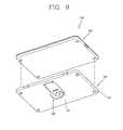
- FIG. 9is a perspective view illustrating another example of a portable electronic apparatus according to another exemplary- embodiment of the present invention.
- an expansion module 360may be mounted at a rear surface of the portable electronic apparatus 300. Electronic elements are incorporated in an expansion body 361 of the expansion module 360, and configured to exchange data or power with a body 310 of the portable electronic apparatus 300.
- the expansion module 360may be an external battery, an external wireless communication module, a monitor, a keyboard, and the like.
- a body 310 of the electronic apparatus 300is mounted on a front surface of the expansion module 360, and a support module 320 is disposed at a rear surface thereof.
- the support module 320supports the expansion body 361 such that the expansion body 361 is disposed in an inclined direction relative to a surface.
- the support unit 321is mounted on a rear surface of the expansion body 361, and configured to be relatively rotated to the expansion body 361 between a first configuration disposed to cover a rear surface of the expansion body 361 and a second configuration in which one end thereof is apart from the rear surface of the expansion body 361.
- An elastic unit(not shown) is mounted on the expansion body 361, and formed to apply elastic force to the support unit 321 in the direction of rotating the support unit 321 to the first configuration.
- a guide unit(not shown) is disposed between the expansion body 361 and the support unit 321 to guide the rotation of the support unit 321.
- a main body thereofis placed by using friction force and elastic force, thereby forming a support or placement mechanism in which the main body can be freely fixed with respect to the floor within a specific angle range.
- a portable electronic apparatusin which the support unit is automatically accommodated therein when the placement is released in a manner that an elastic unit thereof applies elastic force in the direction of restoring the support unit may be implemented.
Landscapes
- Engineering & Computer Science (AREA)
- Theoretical Computer Science (AREA)
- Computer Hardware Design (AREA)
- General Engineering & Computer Science (AREA)
- Human Computer Interaction (AREA)
- Physics & Mathematics (AREA)
- General Physics & Mathematics (AREA)
- Telephone Set Structure (AREA)
- Casings For Electric Apparatus (AREA)
Description
- The present invention relates to portable electronic apparatus, and more particularly to, a portable electronic apparatus that can be placed to make a specific angle with a surface.
- A portable electronic apparatus is an electronic device that is portable and may include voice and video communication functions, an information input, an output function, a data storage function, and the like. As the functions become diversified, the terminal is implemented in the form of a multimedia player having complicated functions such as capturing still or moving images, playing music or video files, receiving broadcast signals, and the like.
- In order to implement such complicated functions of a multimedia player, various changes have been made to the hardware and software of the portable electronic device. As an example, a user interface environment is provided to allow the user to easily and conveniently retrieve or select the functions of the multimedia player. However, when considering the portability of an portable electronic apparatus, it may be accompanied by the limitation of making it difficult to place the portable electronic apparatus on a table or the like. Accordingly, a device for more easily placing the portable electronic apparatus on a surface may be considered.
US 2007/211420 A1 relates to a portable electronic device including a main body, a display part provided in the main body and displaying an image thereon, a main stand which is coupled with a rear part of the main body to adjust a supporting angle of the main body, and an auxiliary stand which is coupled with either the main body or the main stand, to adjust the supporting angle of the main body.US 5 253 292 A relates to a carrier assembly for an electronic device, such as a radiotelephone. The carrier assembly is comprised of a frame and a support arm pivotally coupled thereto. The frame receives the electronic device to engage supportively the electronic device thereat, and latch members latch the electronic device to the frame. The support arm is pivotally coupled to the frame to permit positioning of the support arm to form either a clip or a table-support. When positioned to form a clip, the carrier assembly permits carriage of the electronic device by way of supportive engagement of the device to an external object, such as a belt or other article of clothing, of a user. When positioned at the table-support position, the support arm is operative to support the electronic device in a desired orientation upon a surface.US 2007/062089 A1 relates to a display device comprising a housing adapted to support a display screen. The display device also comprises a kickstand support positionable to support the housing in at least two different viewing modes.- Accordingly, the present invention is directed to a portable electronic apparatus that substantially obviates one or more problems due to limitations and disadvantages of the related art.
- An object of the present invention is to provide a portable electronic apparatus that can be more easily placed on a surface and within a specific angle range.
- Another object of the present invention is to provide a portable electronic apparatus in which the state of a support module is automatically changed.
- Additional features and advantages of the invention will be set forth in the description which follows, and in part will be apparent from the description, or may be learned by practice of the invention. The objectives and other advantages of the invention will be realized and attained by the structure particularly pointed out in the written description and claims hereof as well as the appended drawings.
- To achieve these and other advantages and in accordance with the purpose of the present invention, as embodied and broadly described, the portable electronic apparatus includes a portable electronic apparatus including a main body having a front portion and a rear portion, a display unit disposed on the front portion, and a support module disposed on the rear portion, the support module operable to support the main body at an incline relative to a surface, the support module including a support unit, a free end of the support unit being disposed on the rear portion in a first configuration and the free end of the support unit being disposed apart from the rear portion in a second configuration, a guide unit, the guide unit being disposed between the main body and the support unit to guide the rotation of the support unit, and an elastic unit, the elastic unit being connected to the support unit and the rear portion so as to apply an elastic force to the support unit in the direction of rotation of the support unit.
- In another aspect, the portable electronic apparatus includes an expansion module for a portable electronic apparatus, the module including an expansion body connected to a rear portion of the portable electronic apparatus, the expansion body operable to exchange data or power with the portable electronic apparatus, and a support module disposed on the rear surface of the expansion body, the support module operable to support the expansion body and the portable electronic apparatus at an incline relative to a surface, the support module including a support unit, a free end of the support unit being disposed on the rear portion in a first configuration and the free end of the support unit being disposed apart from the rear portion in a second configuration, a guide unit, the guide unit being disposed between the main body and the support unit to guide the rotation of the support unit, and an elastic unit, the elastic unit being connected to the support unit and the rear portion so as to apply an elastic force to the support unit in the direction of rotation of the support unit.
- It is to be understood that both the foregoing general description and the following detailed description are exemplary and explanatory and are intended to provide further explanation of the invention as claimed.
- The accompanying drawings, which are included to provide a further understanding of the invention and are incorporated in and constitute a part of this specification, illustrate embodiments of the invention and together with the description serve to explain the principles of the invention. In the drawings:
FIG. 1 is a perspective view of an exemplary portable electronic apparatus according to an exemplary embodiment of the present invention;FIG. 2 is a rear perspective view of the exemplary portable electronic apparatus illustrated inFIG. 1 ;FIG. 3 is a perspective view illustrating an exemplary support unit that is rotated to support a body of the exemplary portable electronic apparatus ofFIG. 2 ;FIG. 4 is a side view illustrating the exemplary portable electronic apparatus ofFIG. 3 ;FIGs. 5A and 5B are conceptual views illustrating the operation of an exemplary support module in the portable electronic apparatus ofFIG. 3 ;FIG. 6 is an exploded perspective view illustrating an exemplary support module ofFIG. 3 ;FIG. 7 is a conceptual view illustrating the operation of an exemplary rotation unit ofFIG. 3 ;FIG. 8 is a conceptual view illustrating a modified example of an exemplary accommodation portion ofFIG. 3 ; andFIG. 9 is a perspective view illustrating another example of a portable electronic apparatus according to another exemplary embodiment of the present invention.- Reference will now be made in detail to the embodiments of the present invention, examples of which are illustrated in the accompanying drawings.
FIG. 1 is a perspective view illustrating a portableelectronic apparatus 100 according to an exemplary embodiment of the present invention.FIG. 1 illustrates a tablet PC as an example of the portable electronic apparatus. However, a portable electronic apparatus may also include a laptop computer, smart phone, digital broadcasting terminal, personal digital assistant (PDA), portable multimedia player (PMP), navigator, or the like.- The portable
electronic apparatus 100 includes a body (or main body) 110. However, the present invention will not be limited to this, but may also be applicable to various structures, such as mobile devices having at least two bodies coupled to each other, for example, a flip phone or laptop. The body may include a case (housing, casing, cover, etc.) forming the outside of the portableelectronic apparatus 100. The case may be divided into afront case 111 and arear case 112. In addition, various electronic components may be incorporated into a space between thefront case 111 and therear case 112. At least one intermediate case may be additionally disposed between thefront case 111 and therear case 112. In addition, the cases may be formed of a resin by injection molding, or formed of metallic materials such as stainless steel (STS) and titanium (Ti). - A
display unit 113, anaudio output module 114, acamera 115, auser input unit 116 and the like may be disposed on the electronic apparatus body, particularly, on thefront case 111. Thedisplay unit 113 may occupy most of a principal surface of thefront case 111. The principal surface of thefront case 111 may be referred to as a front surface of the electronic apparatus body. Thedisplay unit 113 is provided to display visible information or image information, and thedisplay unit 113 may include at least one of a liquid crystal display (LCD), a thin film transistor LCD (TFT-LCD), an organic light emitting diode (OLED) display, a flexible display, or a three-dimensional (3D) display. Thedisplay unit 113 may include a touchpad for allowing a user's touch input. In this case, thedisplay unit 113 may operate as a touch screen. - The
display unit 113 may output various types of visible information. Such information may be outputted in various forms, such as letters, numbers, symbols, graphics, icons or the like. For input of such information, at least one of the letters, numbers, symbols, graphics or icons may be displayed in a present arrangement, thereby implementing a type of keypad, which may be called as 'soft key.' - The display unit may operate as an overall region, or by being divided into plural regions. In the latter case, the plurality of regions may be configured to cooperatively operate together.
- The
user input unit 116 may be manipulated to receive commands for controlling operations of themobile device 100, and include a plurality ofmanipulation units manipulation units manipulation units - The information input via the plurality of
manipulation units first manipulation unit 116a may be used to receive a command such as START, END, etc., and thesecond manipulation unit 116b may be used to receive a command such as SCROLL or the like, or a command such as volume adjustment of sound output from theaudio output module 114. - The
audio output module 114 and thecamera 115 may be located at a region adjacent to a side of thedisplay unit 113. Theaudio output module 114 may include a speaker, a receiver, and the like. Also, thecamera 115 may be provided in the electronic apparatus body in a rotatable or pop-up manner. - A controller for controlling the
display unit 113 and theuser input unit 116 may be disposed in the body. The controller may be implemented as a printed circuit board. FIG. 2 is a rear perspective view of the exemplary portableelectronic apparatus 100 ofFIG. 1 .- An audio output module may further be disposed at a rear surface of the portable electronic apparatus body. The audio output module may cooperate with the audio output module 114 (refer to
FIG. 1 ) to implement a stereo function. Also, the audio output module may be used to implement a speakerphone mode. - A wireless communication or broadcast signal reception antenna may be disposed at a side surface of the mobile device body. Also, the antenna may be provided in a retractable manner in the portable electronic apparatus body.
- Referring to the drawings, the portable electronic apparatus body may include a
microphone 117, aconnection port 118, and the like. Themicrophone 117 may be disposed far from theaudio output module 114. For example, themicrophone 117 may be disposed at an opposite side of theaudio output module 114 relative to the display unit. - The
connection port 118 and the like may be located at lateral surfaces of thefront case 111 and therear case 112. Theconnection port 118 may include at least one of a connection terminal for wired or wireless connection to an earphone, a port for short-range communication (e.g., infrared (IrDA) port, Bluetooth port, wireless LAN port, etc.), or a power supply terminal for supplying power to the portable electronic apparatus. Theconnection port 118 may also include a card socket for accommodating an external card such as subscriber identification module (SIM), user identity module (UIM), memory card for storing information, or the like. - A power supply unit for supplying power to the
mobile device 100 may be mounted on the mobile device body. The power supply unit may be a built-in battery to be mounted inside the body. FIG. 3 is a perspective view illustrating anexemplary support unit 121 that is rotated to support a body of the exemplary portableelectronic apparatus 100 ofFIG. 2 .FIG. 4 is a side view illustrating the exemplary portable electronic apparatus ofFIG. 3 .FIGs. 5A and 5B are conceptual views illustrating the operation of anexemplary support module 120 in the portable electronic apparatus ofFIG. 3 .- As shown in the drawings, a
support module 120 for supporting the body is mounted on a portable electronic apparatus body such that the body is disposed in an inclined direction relative to a surface S (refer toFIG. 5A ). Here, the surface S denotes a portion where a portable electronic apparatus may be placed, such as a desk, a table, a sitting person's thighs, or the like. - The
support module 120 may include asupport unit 121, an elastic unit 122 (refer toFIG. 4 ), and aguide unit 123. - The
support unit 121 is mounted on a rear surface of anelectronic apparatus body 110, and configured to be relatively rotated to thebody 110 between a first configuration (refer toFIG. 2 ) disposed to cover a rear surface of thebody 110 and a second configuration (refer toFIG. 3 ) in which one end thereof is apart from the rear surface of thebody 110. A rear surface of theelectronic apparatus body 110 may be an outer surface of arear case 112, and thesupport unit 121 may be formed in a bar shape. - The
elastic unit 122 is mounted on theelectronic apparatus body 110, and formed to apply elastic force to thesupport unit 121 in the direction of rotating thesupport unit 121 to the first configuration. More specifically, if thesupport unit 121 is rotated from the first configuration to the second configuration, then theelastic unit 122 is transformed to apply elastic force in the direction of restoring thesupport unit 121 to the first configuration. For such an example, theelastic unit 122 may be a coil spring such that both ends thereof are connected to a side of thesupport unit 121 and a rear surface side of theelectronic apparatus body 110, respectively. - As shown in
FIG. 5A , thesupport unit 121 supports a rear surface of the electronic apparatus body in a state that a lateral surface of theelectronic apparatus body 110 and an end of thesupport unit 121 are brought into contact with a surface S, respectively. At this time, a lateral surface of theelectronic apparatus body 110 and an end of thesupport unit 121 are subject to a force being applied in opposing directions such that the they are placed apart from each other. If the force is balanced with the sum of an elastic force of theelastic unit 122 and a friction force to the surface S, then theelectronic apparatus 100 may be placed at a tilt with respect to the surface S (hereinafter, referred to as "placement state"). - As shown in
FIG. 5B , if one end of thesupport unit 121 is released from the contact with the surface S in the placement state, then thesupport unit 121 is restored to the first configuration by the elastic force of theelastic unit 122. As a result, the user can carry a portable electronic apparatus in a form that the volume occupied by thesupport unit 121 orsupport module 120 is reduced. - As shown in
FIGs. 3 ,4 ,5A, and 5B , theguide unit 123 is disposed between theelectronic apparatus body 110 and thesupport unit 121. Theguide unit 123 is formed to guide the rotation of thesupport unit 121. More specifically, one end of theguide unit 123 is rotatably mounted on a rear surface of theelectronic apparatus body 110, and the other end thereof is slide-ably combined with thesupport unit 121. FIG. 6 is an exploded perspective view illustrating anexemplary support module 120 ofFIG. 3 .FIG. 7 is a conceptual view illustrating the operation of an exemplary rotation unit ofFIG. 3 . Thesupport module 120 will be described in more detail.- As illustrated in the drawings, one end of the
support unit 121 forms a free end, and the other end thereof is rotatably mounted on thebody 110. More specifically, thesupport unit 121 is mounted on therotation unit 130. Therotation unit 130 is mounted on theelectronic apparatus body 110 to be rotated around a first axis (S1) perpendicular to a rear surface of thebody 110. Therotation unit 130 may include acircular portion 131 and anextension portion 132. - The
circular portion 131 is formed in a circular shape around the first axis, and rotatably engaged with apivot engagement portion 119 of theelectronic apparatus body 110 using apivot unit 133. Aninsertion hole 131a is formed on an outer circumference of thecircular portion 131 in a radial direction, and aprotrusion 121a is provided at an end portion of thesupport unit 121 to be inserted into theinsertion hole 131a. In other words, theprotrusion 121a is fitted in theinsertion hole 131a, and thesupport unit 121 is rotated around theprotrusion 121a. In other words, thesupport unit 121 is rotatably combined with therotation unit 130 around a second axis (S2, central axis of the protrusion) perpendicular to the first axis. - As shown in
FIG. 7 , thesupport unit 121 is formed to be rotated on a plane perpendicular to a rotation plane of therotation unit 130, and therotation unit 130 may be configured to be rotated within a specific rotation range. For example, the rotation range may be located between a configuration in which one end of thesupport unit 121 is in parallel with a lateral surface of theelectronic apparatus body 110 and a configuration in which the one end of thesupport unit 121 is in parallel with a lateral surface perpendicular to the lateral surface. Accordingly, the portable electronic apparatus may be placed in a vertical or horizontal direction. - With reference to
FIG. 6 , anaccommodation portion 140 may be formed at a rear surface of theelectronic apparatus body 110. Theaccommodation portion 140 is recessed at a rear surface of thebody 110 to accommodate thesupport unit 121 on the rear surface of thebody 110. Theaccommodation portion 140 is configured to accommodate therotation unit 130 andsupport unit 121 together, and therotation unit 130 is rotatably mounted on theaccommodation portion 140. More specifically, theaccommodation portion 140 may include acircular region 141 corresponding to thecircular portion 131 of therotation unit 130 and anextension region 142 extended from the circular region to accommodate theextension portion 132 of therotation unit 130 and thesupport unit 121. Accordingly, thesupport module 120 may not protrude from a rear surface of theelectronic apparatus body 110, thereby facilitating the portability of a portable electronic apparatus. - The
extension portion 132 extends from thecircular portion 131 to a direction in parallel to a rear surface of thebody 110, and theguide unit 123 is rotatably combined with theextension portion 132. - The
guide unit 123 is formed in a bar shape, and hingeaxes hinge axes extension portion 132, and ahinge hole 132a may be formed at theextension portion 132. - A
guide groove 124 extending from one end of thesupport unit 121 to the other end thereof is formed on the support unit, and an end portion of the guide unit is configured to slide along theguide groove 124. More specifically, ahinge axis 123b is formed at an end portion opposite to the end of theguide unit 123 combined with theextension portion 132, and both lateral surfaces of the vertical supportingstand 124 are formed to accommodate thehinge axis 123b. - An end of the
elastic unit 122 is connected to therotation unit 130, and the other end thereof is combined with thesupport unit 121 to apply an elastic force to thesupport unit 121. However, the present invention is not limited to this. For example, theelastic unit 122 may be a torsion spring disposed to be elastically transformed in the direction of being wound by the rotation of the support unit. - A first
friction reinforcement portion 151 is formed at an end of thesupport unit 121. If the end of thesupport unit 121 is brought into contact with the surface S (refer toFIG. 5A ), then the firstfriction reinforcement portion 151 is configured to reinforce the friction force of a portion in contact with the surface S. For example, the firstfriction reinforcement portion 151 may includefirst friction units support unit 121. For example,first friction units groove 152 on which first mountingunits support unit 121, and the first mountingunits groove 152. However, the present invention is not limited to this. For example, the firstfriction reinforcement portion 151 may be formed with various shapes such that the surface thereof is roughened or the protrusion thereof is provided, and so on. - A second
friction reinforcement portion 153, together with the firstfriction reinforcement portion 151, may be provided to reinforce the friction force of a portion in contact with the floor. The secondfriction reinforcement portion 153 is illustrated inFIGs. 2 through 4 , and the secondfriction reinforcement portion 153 is formed at a lateral surface of thebody 110 to reinforce the friction force of a portion where a lateral surface of theelectronic apparatus body 110 is brought into contact with the floor. For example, the secondfriction reinforcement portion 153 is mounted at a lateral surface of thebody 110, and may includesecond friction units cases body 110. Thesecond friction units - At least part of the
second friction units FIG. 4 , a lateral surface of thebody 110 mounted with thesecond friction units body 110. Also, the lateral surface of thebody 110 may form an acute angle (A1) with respect to a cross-section of the bodyelectronic apparatus body 110. Accordingly, when an electronic apparatus is placed to be inclined relative to the surface S (refer toFIG. 5A ), an area where thesecond friction units FIG. 8 is a conceptual view illustrating a modified example of an exemplary accommodation portion ofFIG. 3 .- An
accommodation portion 240 may include acircular region 241 corresponding to the circular portion 231 of therotation unit 230 and a plurality ofextension regions circular region 241 to both directions perpendicular to each other. - The
extension regions rotation unit 230 and asupport unit 221, and through this, thesupport module 220 may be accommodated in a rear surface of theelectronic apparatus body 210 in any one of a plurality of configurations. In other words, if the floor is released from the contact with thesupport unit 221, then thesupport module 220 is automatically accommodated in theaccommodation portion 240, regardless of the position of a portable electronic apparatus being placed in a horizontal or vertical direction. FIG. 9 is a perspective view illustrating another example of a portable electronic apparatus according to another exemplary- embodiment of the present invention.- As shown in
FIG. 9 , anexpansion module 360 may be mounted at a rear surface of the portableelectronic apparatus 300. Electronic elements are incorporated in anexpansion body 361 of theexpansion module 360, and configured to exchange data or power with abody 310 of the portableelectronic apparatus 300. For example, theexpansion module 360 may be an external battery, an external wireless communication module, a monitor, a keyboard, and the like. - A
body 310 of theelectronic apparatus 300 is mounted on a front surface of theexpansion module 360, and asupport module 320 is disposed at a rear surface thereof. Thesupport module 320 supports theexpansion body 361 such that theexpansion body 361 is disposed in an inclined direction relative to a surface. - The
support unit 321 is mounted on a rear surface of theexpansion body 361, and configured to be relatively rotated to theexpansion body 361 between a first configuration disposed to cover a rear surface of theexpansion body 361 and a second configuration in which one end thereof is apart from the rear surface of theexpansion body 361. An elastic unit (not shown) is mounted on theexpansion body 361, and formed to apply elastic force to thesupport unit 321 in the direction of rotating thesupport unit 321 to the first configuration. A guide unit (not shown) is disposed between theexpansion body 361 and thesupport unit 321 to guide the rotation of thesupport unit 321. With the foregoing configuration, a portable electronic apparatus may be more easily placed even in the state of being combined with an expansion module thereof. - In a portable electronic apparatus having the foregoing configuration associated with the present invention, a main body thereof is placed by using friction force and elastic force, thereby forming a support or placement mechanism in which the main body can be freely fixed with respect to the floor within a specific angle range. In addition, a portable electronic apparatus in which the support unit is automatically accommodated therein when the placement is released in a manner that an elastic unit thereof applies elastic force in the direction of restoring the support unit may be implemented.
Claims (13)
- A portable electronic apparatus comprising:a main body having a front portion and a rear portion;a display unit (113) disposed on the front portion; anda support module (120, 220, 320) disposed on the rear portion, the support module operable to support the main body at an incline relative to a surface, the support module (120, 220, 320) including:a support unit (121, 221, 321), a free end of the support unit being disposed on the rear portion in a first configuration and the free end of the support unit being disposed apart from the rear portion in a second configuration; anda guide unit (123), the guide unit being disposed between the main body and the support unit to guide the rotation of the support unit;characterized in thatthe support module (120) is rotatably connected to the main body around a first axis (S1) perpendicular to the rear portion of the main body, the support module (120) further including a rotation unit (130, 230), the support unit being rotatably connected to the rotation unit around a second axis (S2) perpendicular to the first axis,wherein the rotation unit (130, 230) comprises a circular portion (131) formed in a circular shape around the first axis, and an extension portion (132) extended from the circular portion in a direction in parallel with the rear portion of the main body, wherein the guide unit (123) is rotatably combined with the extension portion (132); and an elastic unit is connected to the support unit and the circular portion so as to apply an elastic force to the support unit in the direction of rotation of the support unit.
- The portable electronic apparatus according to claim 1, wherein the support unit (121, 221, 321) is disposed in the first configuration by the elastic force of the elastic unit (122) when the free end of the support unit (121) is not in contact with the surface.
- The portable electronic apparatus according to claim 1 or 2, wherein the free end of the support unit (121, 221, 321) is operable to contact the surface and the other end is rotatably connected to the rotation unit.
- The portable electronic apparatus according to claim 3, further comprising a first friction reinforcement portion (151) formed at the free end of the support unit (121, 221, 321), the first friction reinforcement portion (151) configured to increase the friction force between the free end of the support unit and the surface.
- The portable electronic apparatus according to claim 4, wherein the first friction reinforcement portion includes a first friction unit (151a, 151b) formed with a material having a frictional coefficient greater than that of the support unit (121, 221, 321).
- The portable electronic apparatus according to any one of claims 1 to 5, wherein the guide unit (123) is configured such that a first end of the guide unit is rotatably connected to the extension portion and a second end of the guide unit is slide-ably connected to the support unit.
- The portable electronic apparatus according to claim 6, wherein the support unit (121, 221, 321) includes a guide groove (124) extending from one end of the support unit to the other end of the support unit is formed on the support unit, the second end of the guide unit configured to slide along the guide groove.
- The portable electronic apparatus according to any one of claims 1 to 7, further comprising a second friction reinforcement portion (153) formed on a lateral surface of the main body to reinforce the friction force of a portion where the lateral surface of the main body is brought into contact with the surface.
- The portable electronic apparatus according to claim 8, wherein the second friction reinforcement (153) includes a second friction unit (153a, 153b) formed with a material having a frictional coefficient greater than that of a case of the main body.
- The portable electronic apparatus according to claim 9, wherein the lateral surface of the main body having the second friction unit is inclined to make an obtuse angle with a rear surface of the main body.
- The portable electronic apparatus according to any one of claims 1 to 10, wherein the rear portion includes a recessed accommodation portion (140), the recessed accommodation portion operable to store the support module.
- The portable electronic apparatus according to claim 11 wherein the rotation unit (130, 230) connected to the support unit is rotatably mounted in the accommodation portion, the support unit operable to rotate on a plane perpendicular to a rotation plane of the rotation unit.
- The portable electronic apparatus according to claim 12, wherein the rotation unit (130, 230) is provided with a rotation range between a configuration in which one end of the support unit is in parallel with a lateral surface of the main body and a configuration in which the one end of the support unit is in parallel with a lateral surface perpendicular to the lateral surface.
Applications Claiming Priority (1)
| Application Number | Priority Date | Filing Date | Title |
|---|---|---|---|
| KR1020100025472AKR101105841B1 (en) | 2010-03-22 | 2010-03-22 | Portable electronic devices |
Publications (3)
| Publication Number | Publication Date |
|---|---|
| EP2369439A2 EP2369439A2 (en) | 2011-09-28 |
| EP2369439A3 EP2369439A3 (en) | 2014-04-02 |
| EP2369439B1true EP2369439B1 (en) | 2015-12-23 |
Family
ID=42809950
Family Applications (1)
| Application Number | Title | Priority Date | Filing Date |
|---|---|---|---|
| EP10008537.2AActiveEP2369439B1 (en) | 2010-03-22 | 2010-08-16 | Portable electronic apparatus |
Country Status (4)
| Country | Link |
|---|---|
| US (1) | US8593798B2 (en) |
| EP (1) | EP2369439B1 (en) |
| KR (1) | KR101105841B1 (en) |
| CN (1) | CN102202478B (en) |
Families Citing this family (31)
| Publication number | Priority date | Publication date | Assignee | Title |
|---|---|---|---|---|
| US8913009B2 (en) | 2010-02-03 | 2014-12-16 | Nintendo Co., Ltd. | Spatially-correlated multi-display human-machine interface |
| KR101154636B1 (en) | 2010-02-03 | 2012-06-08 | 닌텐도가부시키가이샤 | Display device, game system, and game method |
| US20120111881A1 (en)* | 2010-06-07 | 2012-05-10 | 360 Mobility Solutions, Llc | Protective cases for electronic devices |
| US20120103855A1 (en)* | 2010-06-07 | 2012-05-03 | 360 Mobility Solutions, Llc | Cases for electronic devices |
| US20120113572A1 (en)* | 2010-06-07 | 2012-05-10 | 360 Mobility Solutions, Llc | Method and system for electronic device cases |
| US20110299231A1 (en)* | 2010-06-07 | 2011-12-08 | Gaddis Ii Scott Carter | Rotatable Cases For Electronic Devices |
| JP6243586B2 (en) | 2010-08-06 | 2017-12-06 | 任天堂株式会社 | GAME SYSTEM, GAME DEVICE, GAME PROGRAM, AND GAME PROCESSING METHOD |
| JP5840385B2 (en) | 2010-08-30 | 2016-01-06 | 任天堂株式会社 | GAME SYSTEM, GAME DEVICE, GAME PROGRAM, AND GAME PROCESSING METHOD |
| JP5840386B2 (en) | 2010-08-30 | 2016-01-06 | 任天堂株式会社 | GAME SYSTEM, GAME DEVICE, GAME PROGRAM, AND GAME PROCESSING METHOD |
| KR101364826B1 (en) | 2010-11-01 | 2014-02-20 | 닌텐도가부시키가이샤 | Operating apparatus and operating system |
| CN103092260B (en)* | 2011-10-28 | 2016-01-20 | 英业达股份有限公司 | portable electronic device |
| KR101301722B1 (en)* | 2011-12-13 | 2013-08-30 | 주식회사 다이아벨 | Standing Apparatus for mobile device |
| CN103186170B (en)* | 2011-12-27 | 2017-07-11 | 株式会社东芝 | It is determined that for the method and the electronic equipment of the size of the electronic equipment of external equipment |
| USRE48963E1 (en) | 2012-03-02 | 2022-03-08 | Microsoft Technology Licensing, Llc | Connection device for computing devices |
| US9460029B2 (en)* | 2012-03-02 | 2016-10-04 | Microsoft Technology Licensing, Llc | Pressure sensitive keys |
| KR101951385B1 (en) | 2012-08-29 | 2019-02-25 | 삼성전자 주식회사 | A protection cover for cradle of dual-directional and multi-angle |
| US9644783B2 (en)* | 2013-03-16 | 2017-05-09 | James A Rinner | Phone camera tablet bipod support system |
| US9596914B2 (en)* | 2013-04-19 | 2017-03-21 | Joseph A. Zaloom | Tablet transformer |
| KR102206384B1 (en)* | 2014-01-07 | 2021-01-22 | 엘지전자 주식회사 | Portable termnal |
| CN203968178U (en)* | 2014-06-25 | 2014-11-26 | 合肥京东方显示光源有限公司 | A kind of device for mobile communication |
| CN104216475B (en)* | 2014-08-22 | 2017-09-22 | 联想(北京)有限公司 | A kind of electronic equipment |
| CN104869187A (en)* | 2015-04-28 | 2015-08-26 | 江苏卡罗卡国际动漫城有限公司 | Newspaper reading mobile phone with support plate |
| CN108700911A (en)* | 2016-03-11 | 2018-10-23 | 惠普发展公司,有限责任合伙企业 | Holder for computing device |
| JP6572825B2 (en)* | 2016-05-18 | 2019-09-11 | 富士通コネクテッドテクノロジーズ株式会社 | Electronics |
| US10201221B1 (en) | 2017-10-23 | 2019-02-12 | Getac Technology Corporation | Hand strap |
| US10691176B2 (en)* | 2018-07-12 | 2020-06-23 | Google Llc | Textured pattern surface for a computing device |
| KR102824714B1 (en)* | 2019-02-26 | 2025-06-24 | 삼성전자주식회사 | A Mounting device for an electronic device |
| US11301003B2 (en)* | 2019-09-24 | 2022-04-12 | Getac Technology Corporation | Eletronic device with anti-shock function |
| CN111781996A (en)* | 2020-06-30 | 2020-10-16 | 联想(北京)有限公司 | Electronic equipment |
| WO2024096369A1 (en)* | 2022-11-04 | 2024-05-10 | 삼성전자 주식회사 | Support accessory and electronic device case comprising same |
| KR102736199B1 (en)* | 2023-03-08 | 2024-11-28 | 엘지전자 주식회사 | Display device |
Family Cites Families (12)
| Publication number | Priority date | Publication date | Assignee | Title |
|---|---|---|---|---|
| US5253292A (en)* | 1991-08-28 | 1993-10-12 | Motorola, Inc. | Portable radiotelephone support assembly |
| JPH1091281A (en)* | 1996-08-19 | 1998-04-10 | Internatl Business Mach Corp <Ibm> | Information processing device |
| KR20020039201A (en)* | 2000-11-20 | 2002-05-25 | 박창복 | Frame for providing auto fold preventing apparatus |
| CN1991091A (en) | 2003-10-01 | 2007-07-04 | 邱则有 | Form component |
| KR100662367B1 (en)* | 2004-05-06 | 2007-01-02 | 엘지전자 주식회사 | Stand assembly for monitor |
| US20070062089A1 (en)* | 2005-08-31 | 2007-03-22 | Homer Steven S | Display device |
| KR100846898B1 (en)* | 2005-12-30 | 2008-07-17 | 엘지전자 주식회사 | Stand of video display device |
| KR20070092044A (en)* | 2006-03-08 | 2007-09-12 | 삼성전자주식회사 | Portable Electronic Device |
| US20080251663A1 (en)* | 2007-04-11 | 2008-10-16 | Tracy Mark S | Anti-skid foot assembly |
| CN101414200A (en)* | 2007-10-19 | 2009-04-22 | 富准精密工业(深圳)有限公司 | Apparatus with angle adjustment function and angle adjusting device thereof |
| TWI352277B (en)* | 2007-12-07 | 2011-11-11 | Asustek Comp Inc | Foldable portable electronic device and dual mode |
| KR101454238B1 (en)* | 2008-01-21 | 2014-11-03 | 엘지전자 주식회사 | Extension module and portable terminal having the same |
- 2010
- 2010-03-22KRKR1020100025472Apatent/KR101105841B1/enactiveActive
- 2010-08-16EPEP10008537.2Apatent/EP2369439B1/enactiveActive
- 2010-09-16CNCN201010289938.1Apatent/CN102202478B/enactiveActive
- 2010-09-30USUS12/895,091patent/US8593798B2/enactiveActive
Also Published As
| Publication number | Publication date |
|---|---|
| EP2369439A3 (en) | 2014-04-02 |
| KR20110106199A (en) | 2011-09-28 |
| US20110228457A1 (en) | 2011-09-22 |
| KR101105841B1 (en) | 2012-01-16 |
| EP2369439A2 (en) | 2011-09-28 |
| CN102202478A (en) | 2011-09-28 |
| US8593798B2 (en) | 2013-11-26 |
| CN102202478B (en) | 2015-09-16 |
Similar Documents
| Publication | Publication Date | Title |
|---|---|---|
| EP2369439B1 (en) | Portable electronic apparatus | |
| US10503215B1 (en) | Multi-form factor information handling system (IHS) with attachable keyboard | |
| US8264823B2 (en) | Foldable mobile terminal | |
| KR101917683B1 (en) | Mobile device | |
| US8358513B2 (en) | Expansion module for mobile device and mobile device having the same | |
| CN102196690B (en) | Module for expanding function of mobile device and mobile device having the same | |
| EP2247081B1 (en) | Mobile terminal comprising a main body, a tilting body and a sliding body | |
| US11137797B2 (en) | Adjustable stand and mobile computing device system | |
| US9116670B2 (en) | Surface contact for a support component | |
| CN108604109B (en) | Electronic equipment with prop-up function | |
| US6585217B2 (en) | Electronic instrument supporting apparatus for use with input device | |
| US20070211420A1 (en) | Portable electronic device | |
| US8878890B2 (en) | Mobile terminal | |
| KR20100019164A (en) | Controlling a mobile terminal with a flexible display | |
| KR20140099006A (en) | Moblie Terminal | |
| US9179567B2 (en) | Electronic device | |
| EP2381653B1 (en) | Portable electronic apparatus having a connection port | |
| KR101635029B1 (en) | Mobile terminal | |
| CN209748968U (en) | Protective shell and electronic equipment with same | |
| JP2014107714A (en) | Portable terminal device | |
| KR20170116854A (en) | Protecting cover | |
| EP3821318B1 (en) | Adjustable stand and mobile computing device system | |
| WO2009144722A1 (en) | Flexible flat screen display device | |
| KR20140133338A (en) | Moblie apparatus and hinge module used therein | |
| KR102002392B1 (en) | Protecting cover |
Legal Events
| Date | Code | Title | Description |
|---|---|---|---|
| PUAI | Public reference made under article 153(3) epc to a published international application that has entered the european phase | Free format text:ORIGINAL CODE: 0009012 | |
| AK | Designated contracting states | Kind code of ref document:A2 Designated state(s):AL AT BE BG CH CY CZ DE DK EE ES FI FR GB GR HR HU IE IS IT LI LT LU LV MC MK MT NL NO PL PT RO SE SI SK SM TR | |
| AX | Request for extension of the european patent | Extension state:BA ME RS | |
| PUAL | Search report despatched | Free format text:ORIGINAL CODE: 0009013 | |
| AK | Designated contracting states | Kind code of ref document:A3 Designated state(s):AL AT BE BG CH CY CZ DE DK EE ES FI FR GB GR HR HU IE IS IT LI LT LU LV MC MK MT NL NO PL PT RO SE SI SK SM TR | |
| AX | Request for extension of the european patent | Extension state:BA ME RS | |
| RIC1 | Information provided on ipc code assigned before grant | Ipc:G06F 1/16 20060101AFI20140227BHEP | |
| 17P | Request for examination filed | Effective date:20140319 | |
| RBV | Designated contracting states (corrected) | Designated state(s):AL AT BE BG CH CY CZ DE DK EE ES FI FR GB GR HR HU IE IS IT LI LT LU LV MC MK MT NL NO PL PT RO SE SI SK SM TR | |
| GRAP | Despatch of communication of intention to grant a patent | Free format text:ORIGINAL CODE: EPIDOSNIGR1 | |
| INTG | Intention to grant announced | Effective date:20150716 | |
| RAP1 | Party data changed (applicant data changed or rights of an application transferred) | Owner name:LG ELECTRONICS INC. | |
| GRAS | Grant fee paid | Free format text:ORIGINAL CODE: EPIDOSNIGR3 | |
| GRAA | (expected) grant | Free format text:ORIGINAL CODE: 0009210 | |
| AK | Designated contracting states | Kind code of ref document:B1 Designated state(s):AL AT BE BG CH CY CZ DE DK EE ES FI FR GB GR HR HU IE IS IT LI LT LU LV MC MK MT NL NO PL PT RO SE SI SK SM TR | |
| REG | Reference to a national code | Ref country code:GB Ref legal event code:FG4D | |
| REG | Reference to a national code | Ref country code:CH Ref legal event code:EP | |
| REG | Reference to a national code | Ref country code:IE Ref legal event code:FG4D | |
| REG | Reference to a national code | Ref country code:AT Ref legal event code:REF Ref document number:766806 Country of ref document:AT Kind code of ref document:T Effective date:20160115 | |
| REG | Reference to a national code | Ref country code:DE Ref legal event code:R096 Ref document number:602010029631 Country of ref document:DE | |
| REG | Reference to a national code | Ref country code:NL Ref legal event code:FP | |
| REG | Reference to a national code | Ref country code:LT Ref legal event code:MG4D | |
| PG25 | Lapsed in a contracting state [announced via postgrant information from national office to epo] | Ref country code:NO Free format text:LAPSE BECAUSE OF FAILURE TO SUBMIT A TRANSLATION OF THE DESCRIPTION OR TO PAY THE FEE WITHIN THE PRESCRIBED TIME-LIMIT Effective date:20160323 Ref country code:LT Free format text:LAPSE BECAUSE OF FAILURE TO SUBMIT A TRANSLATION OF THE DESCRIPTION OR TO PAY THE FEE WITHIN THE PRESCRIBED TIME-LIMIT Effective date:20151223 Ref country code:HR Free format text:LAPSE BECAUSE OF FAILURE TO SUBMIT A TRANSLATION OF THE DESCRIPTION OR TO PAY THE FEE WITHIN THE PRESCRIBED TIME-LIMIT Effective date:20151223 | |
| REG | Reference to a national code | Ref country code:AT Ref legal event code:MK05 Ref document number:766806 Country of ref document:AT Kind code of ref document:T Effective date:20151223 | |
| PG25 | Lapsed in a contracting state [announced via postgrant information from national office to epo] | Ref country code:FI Free format text:LAPSE BECAUSE OF FAILURE TO SUBMIT A TRANSLATION OF THE DESCRIPTION OR TO PAY THE FEE WITHIN THE PRESCRIBED TIME-LIMIT Effective date:20151223 Ref country code:LV Free format text:LAPSE BECAUSE OF FAILURE TO SUBMIT A TRANSLATION OF THE DESCRIPTION OR TO PAY THE FEE WITHIN THE PRESCRIBED TIME-LIMIT Effective date:20151223 Ref country code:GR Free format text:LAPSE BECAUSE OF FAILURE TO SUBMIT A TRANSLATION OF THE DESCRIPTION OR TO PAY THE FEE WITHIN THE PRESCRIBED TIME-LIMIT Effective date:20160324 Ref country code:SE Free format text:LAPSE BECAUSE OF FAILURE TO SUBMIT A TRANSLATION OF THE DESCRIPTION OR TO PAY THE FEE WITHIN THE PRESCRIBED TIME-LIMIT Effective date:20151223 | |
| REG | Reference to a national code | Ref country code:FR Ref legal event code:PLFP Year of fee payment:7 | |
| PG25 | Lapsed in a contracting state [announced via postgrant information from national office to epo] | Ref country code:CZ Free format text:LAPSE BECAUSE OF FAILURE TO SUBMIT A TRANSLATION OF THE DESCRIPTION OR TO PAY THE FEE WITHIN THE PRESCRIBED TIME-LIMIT Effective date:20151223 Ref country code:IT Free format text:LAPSE BECAUSE OF FAILURE TO SUBMIT A TRANSLATION OF THE DESCRIPTION OR TO PAY THE FEE WITHIN THE PRESCRIBED TIME-LIMIT Effective date:20151223 Ref country code:ES Free format text:LAPSE BECAUSE OF FAILURE TO SUBMIT A TRANSLATION OF THE DESCRIPTION OR TO PAY THE FEE WITHIN THE PRESCRIBED TIME-LIMIT Effective date:20151223 | |
| PG25 | Lapsed in a contracting state [announced via postgrant information from national office to epo] | Ref country code:EE Free format text:LAPSE BECAUSE OF FAILURE TO SUBMIT A TRANSLATION OF THE DESCRIPTION OR TO PAY THE FEE WITHIN THE PRESCRIBED TIME-LIMIT Effective date:20151223 Ref country code:RO Free format text:LAPSE BECAUSE OF FAILURE TO SUBMIT A TRANSLATION OF THE DESCRIPTION OR TO PAY THE FEE WITHIN THE PRESCRIBED TIME-LIMIT Effective date:20151223 Ref country code:SM Free format text:LAPSE BECAUSE OF FAILURE TO SUBMIT A TRANSLATION OF THE DESCRIPTION OR TO PAY THE FEE WITHIN THE PRESCRIBED TIME-LIMIT Effective date:20151223 Ref country code:AT Free format text:LAPSE BECAUSE OF FAILURE TO SUBMIT A TRANSLATION OF THE DESCRIPTION OR TO PAY THE FEE WITHIN THE PRESCRIBED TIME-LIMIT Effective date:20151223 Ref country code:IS Free format text:LAPSE BECAUSE OF FAILURE TO SUBMIT A TRANSLATION OF THE DESCRIPTION OR TO PAY THE FEE WITHIN THE PRESCRIBED TIME-LIMIT Effective date:20160423 Ref country code:SK Free format text:LAPSE BECAUSE OF FAILURE TO SUBMIT A TRANSLATION OF THE DESCRIPTION OR TO PAY THE FEE WITHIN THE PRESCRIBED TIME-LIMIT Effective date:20151223 Ref country code:PT Free format text:LAPSE BECAUSE OF FAILURE TO SUBMIT A TRANSLATION OF THE DESCRIPTION OR TO PAY THE FEE WITHIN THE PRESCRIBED TIME-LIMIT Effective date:20160426 Ref country code:PL Free format text:LAPSE BECAUSE OF FAILURE TO SUBMIT A TRANSLATION OF THE DESCRIPTION OR TO PAY THE FEE WITHIN THE PRESCRIBED TIME-LIMIT Effective date:20151223 | |
| REG | Reference to a national code | Ref country code:DE Ref legal event code:R097 Ref document number:602010029631 Country of ref document:DE | |
| PLBE | No opposition filed within time limit | Free format text:ORIGINAL CODE: 0009261 | |
| STAA | Information on the status of an ep patent application or granted ep patent | Free format text:STATUS: NO OPPOSITION FILED WITHIN TIME LIMIT | |
| PG25 | Lapsed in a contracting state [announced via postgrant information from national office to epo] | Ref country code:DK Free format text:LAPSE BECAUSE OF FAILURE TO SUBMIT A TRANSLATION OF THE DESCRIPTION OR TO PAY THE FEE WITHIN THE PRESCRIBED TIME-LIMIT Effective date:20151223 | |
| 26N | No opposition filed | Effective date:20160926 | |
| PG25 | Lapsed in a contracting state [announced via postgrant information from national office to epo] | Ref country code:BE Free format text:LAPSE BECAUSE OF FAILURE TO SUBMIT A TRANSLATION OF THE DESCRIPTION OR TO PAY THE FEE WITHIN THE PRESCRIBED TIME-LIMIT Effective date:20151223 | |
| PG25 | Lapsed in a contracting state [announced via postgrant information from national office to epo] | Ref country code:SI Free format text:LAPSE BECAUSE OF FAILURE TO SUBMIT A TRANSLATION OF THE DESCRIPTION OR TO PAY THE FEE WITHIN THE PRESCRIBED TIME-LIMIT Effective date:20151223 | |
| PG25 | Lapsed in a contracting state [announced via postgrant information from national office to epo] | Ref country code:MC Free format text:LAPSE BECAUSE OF FAILURE TO SUBMIT A TRANSLATION OF THE DESCRIPTION OR TO PAY THE FEE WITHIN THE PRESCRIBED TIME-LIMIT Effective date:20151223 | |
| REG | Reference to a national code | Ref country code:CH Ref legal event code:PL | |
| PG25 | Lapsed in a contracting state [announced via postgrant information from national office to epo] | Ref country code:CH Free format text:LAPSE BECAUSE OF NON-PAYMENT OF DUE FEES Effective date:20160831 Ref country code:LI Free format text:LAPSE BECAUSE OF NON-PAYMENT OF DUE FEES Effective date:20160831 | |
| REG | Reference to a national code | Ref country code:IE Ref legal event code:MM4A | |
| REG | Reference to a national code | Ref country code:FR Ref legal event code:PLFP Year of fee payment:8 | |
| PG25 | Lapsed in a contracting state [announced via postgrant information from national office to epo] | Ref country code:IE Free format text:LAPSE BECAUSE OF NON-PAYMENT OF DUE FEES Effective date:20160816 | |
| PG25 | Lapsed in a contracting state [announced via postgrant information from national office to epo] | Ref country code:LU Free format text:LAPSE BECAUSE OF NON-PAYMENT OF DUE FEES Effective date:20160816 | |
| PG25 | Lapsed in a contracting state [announced via postgrant information from national office to epo] | Ref country code:CY Free format text:LAPSE BECAUSE OF FAILURE TO SUBMIT A TRANSLATION OF THE DESCRIPTION OR TO PAY THE FEE WITHIN THE PRESCRIBED TIME-LIMIT Effective date:20151223 Ref country code:HU Free format text:LAPSE BECAUSE OF FAILURE TO SUBMIT A TRANSLATION OF THE DESCRIPTION OR TO PAY THE FEE WITHIN THE PRESCRIBED TIME-LIMIT; INVALID AB INITIO Effective date:20100816 | |
| PG25 | Lapsed in a contracting state [announced via postgrant information from national office to epo] | Ref country code:TR Free format text:LAPSE BECAUSE OF FAILURE TO SUBMIT A TRANSLATION OF THE DESCRIPTION OR TO PAY THE FEE WITHIN THE PRESCRIBED TIME-LIMIT Effective date:20151223 Ref country code:MK Free format text:LAPSE BECAUSE OF FAILURE TO SUBMIT A TRANSLATION OF THE DESCRIPTION OR TO PAY THE FEE WITHIN THE PRESCRIBED TIME-LIMIT Effective date:20151223 Ref country code:MT Free format text:LAPSE BECAUSE OF NON-PAYMENT OF DUE FEES Effective date:20160831 | |
| REG | Reference to a national code | Ref country code:FR Ref legal event code:PLFP Year of fee payment:9 | |
| PG25 | Lapsed in a contracting state [announced via postgrant information from national office to epo] | Ref country code:BG Free format text:LAPSE BECAUSE OF FAILURE TO SUBMIT A TRANSLATION OF THE DESCRIPTION OR TO PAY THE FEE WITHIN THE PRESCRIBED TIME-LIMIT Effective date:20151223 | |
| PG25 | Lapsed in a contracting state [announced via postgrant information from national office to epo] | Ref country code:AL Free format text:LAPSE BECAUSE OF FAILURE TO SUBMIT A TRANSLATION OF THE DESCRIPTION OR TO PAY THE FEE WITHIN THE PRESCRIBED TIME-LIMIT Effective date:20151223 | |
| PGFP | Annual fee paid to national office [announced via postgrant information from national office to epo] | Ref country code:GB Payment date:20220705 Year of fee payment:13 | |
| PGFP | Annual fee paid to national office [announced via postgrant information from national office to epo] | Ref country code:FR Payment date:20220705 Year of fee payment:13 | |
| P01 | Opt-out of the competence of the unified patent court (upc) registered | Effective date:20230523 | |
| GBPC | Gb: european patent ceased through non-payment of renewal fee | Effective date:20230816 | |
| PG25 | Lapsed in a contracting state [announced via postgrant information from national office to epo] | Ref country code:GB Free format text:LAPSE BECAUSE OF NON-PAYMENT OF DUE FEES Effective date:20230816 | |
| PG25 | Lapsed in a contracting state [announced via postgrant information from national office to epo] | Ref country code:GB Free format text:LAPSE BECAUSE OF NON-PAYMENT OF DUE FEES Effective date:20230816 Ref country code:FR Free format text:LAPSE BECAUSE OF NON-PAYMENT OF DUE FEES Effective date:20230831 | |
| PGFP | Annual fee paid to national office [announced via postgrant information from national office to epo] | Ref country code:NL Payment date:20240705 Year of fee payment:15 | |
| PGFP | Annual fee paid to national office [announced via postgrant information from national office to epo] | Ref country code:DE Payment date:20240705 Year of fee payment:15 |