EP2368186B1 - Data error recovery in non-volatile memory - Google Patents
Data error recovery in non-volatile memoryDownload PDFInfo
- Publication number
- EP2368186B1 EP2368186B1EP09837801.1AEP09837801AEP2368186B1EP 2368186 B1EP2368186 B1EP 2368186B1EP 09837801 AEP09837801 AEP 09837801AEP 2368186 B1EP2368186 B1EP 2368186B1
- Authority
- EP
- European Patent Office
- Prior art keywords
- data
- memory cells
- memory
- charge
- specified range
- Prior art date
- Legal status (The legal status is an assumption and is not a legal conclusion. Google has not performed a legal analysis and makes no representation as to the accuracy of the status listed.)
- Not-in-force
Links
Images


Classifications
- G—PHYSICS
- G06—COMPUTING OR CALCULATING; COUNTING
- G06F—ELECTRIC DIGITAL DATA PROCESSING
- G06F11/00—Error detection; Error correction; Monitoring
- G06F11/07—Responding to the occurrence of a fault, e.g. fault tolerance
- G06F11/08—Error detection or correction by redundancy in data representation, e.g. by using checking codes
- G—PHYSICS
- G11—INFORMATION STORAGE
- G11C—STATIC STORES
- G11C16/00—Erasable programmable read-only memories
- G11C16/02—Erasable programmable read-only memories electrically programmable
- G11C16/06—Auxiliary circuits, e.g. for writing into memory
- G11C16/34—Determination of programming status, e.g. threshold voltage, overprogramming or underprogramming, retention
- G11C16/3404—Convergence or correction of memory cell threshold voltages; Repair or recovery of overerased or overprogrammed cells
- G—PHYSICS
- G06—COMPUTING OR CALCULATING; COUNTING
- G06F—ELECTRIC DIGITAL DATA PROCESSING
- G06F11/00—Error detection; Error correction; Monitoring
- G06F11/07—Responding to the occurrence of a fault, e.g. fault tolerance
- G06F11/08—Error detection or correction by redundancy in data representation, e.g. by using checking codes
- G06F11/10—Adding special bits or symbols to the coded information, e.g. parity check, casting out 9's or 11's
- G06F11/1008—Adding special bits or symbols to the coded information, e.g. parity check, casting out 9's or 11's in individual solid state devices
- G06F11/1068—Adding special bits or symbols to the coded information, e.g. parity check, casting out 9's or 11's in individual solid state devices in sector programmable memories, e.g. flash disk
- G—PHYSICS
- G06—COMPUTING OR CALCULATING; COUNTING
- G06F—ELECTRIC DIGITAL DATA PROCESSING
- G06F12/00—Accessing, addressing or allocating within memory systems or architectures
- G06F12/16—Protection against loss of memory contents
- G—PHYSICS
- G11—INFORMATION STORAGE
- G11C—STATIC STORES
- G11C29/00—Checking stores for correct operation ; Subsequent repair; Testing stores during standby or offline operation
- G11C29/04—Detection or location of defective memory elements, e.g. cell constructio details, timing of test signals
- G11C29/08—Functional testing, e.g. testing during refresh, power-on self testing [POST] or distributed testing
- G11C29/12—Built-in arrangements for testing, e.g. built-in self testing [BIST] or interconnection details
- G11C29/38—Response verification devices
- G11C29/42—Response verification devices using error correcting codes [ECC] or parity check
- G—PHYSICS
- G11—INFORMATION STORAGE
- G11C—STATIC STORES
- G11C29/00—Checking stores for correct operation ; Subsequent repair; Testing stores during standby or offline operation
- G11C29/52—Protection of memory contents; Detection of errors in memory contents
- G—PHYSICS
- G11—INFORMATION STORAGE
- G11C—STATIC STORES
- G11C29/00—Checking stores for correct operation ; Subsequent repair; Testing stores during standby or offline operation
- G11C29/04—Detection or location of defective memory elements, e.g. cell constructio details, timing of test signals
- G11C2029/0411—Online error correction
Definitions
- Some types of solid state non- volatile memorysuch as flash memory, record binary data by storing a certain amount of electrical charge in a memory cell.
- the voltage level of the stored chargeis compared to a reference voltage.
- the binary value of the data read from that celldepends on whether the voltage of the stored charge is higher or lower than the reference voltage.
- ECCError correcting code
- US 6,542,407discloses techniques of overcoming degradation of apparent charge levels in a row of memory cells caused by subsequently programming an adjacent row, which includes driving the charge levels of the cells to a common level which increases the chance of successfully reading the data.
- US 2008/0123419discloses a method including adjusting programming target voltages and read voltages together over memory life to map memory states to an increasingly wide threshold window, thus reducing errors.
- references to “one embodiment”, “an embodiment”, “example embodiment”, “various embodiments”, etc.,indicate that the embodiment(s) of the invention so described may include particular features, structures, or characteristics, but not every embodiment necessarily includes the particular features, structures, or characteristics. Further, some embodiments may have some, all, or none of the features described for other embodiments.
- Coupledis used to indicate that two or more elements are in direct physical or electrical contact with each other.
- Connectedis used to indicate that two or more elements are in direct physical or electrical contact with each other.
- Connectedis used to indicate that two or more elements are in direct physical or electrical contact with each other.
- Connectedis used to indicate that two or more elements are in direct physical or electrical contact with each other.
- Connectedis used to indicate that two or more elements are in direct physical or electrical contact with each other.
- Coupledis used to indicate that two or more elements co-operate or interact with each other, but they may or may not be in direct physical or electrical contact.
- Various embodiments of the inventionmay be implemented in one or any combination of hardware, firmware, and software.
- the inventionmay also be implemented as instructions contained in or on a computer-readable medium, which may be read and executed by one or more processors to enable performance of the operations described herein.
- a computer-readable mediummay include any mechanism for storing, transmitting, and/or receiving information in a form readable by one or more computers.
- a computer-readable mediummay include a tangible storage medium, such as but not limited to read only memory (ROM); random access memory (RAM); magnetic disk storage media; optical storage media; a flash memory device, etc.
- a computer-readable mediummay also include a propagated signal which has been modulated to encode the instructions, such as but not limited to electromagnetic, optical, or acoustical carrier wave signals.
- a processmay be followed to attempt to correct the data. Since the exact location of the bad data may not be known, this process may comprise 1) identifying 'low confidence' (LC) storage cells in that portion of memory (i.e., cells that are more likely than other cells to contains errors), 2) determining what data in those cells is likely to be correct, and 3) verifying that the new data is correct. Identifying low confidence cells may be done in either of two ways: 1) find cells whose analog charge voltage is close to a reference voltage, or 2) look for particular patterns of charge levels in the surrounding cells that are known to cause data corruption in a target cell.
- LClow confidence'
- Determining new data that is likely to be correct in the low confidence cellsmay be done in either of two ways: 1) adjust the analog charge value in those cells in a direction and amount that seems best, or 2) try random values of data in the LC cells. Verifying that the new data is correct may be performed in any suitable manner, but may typically be done by using an error checking and correction (ECC) algorithm, since this will produce valid data as long as the number of errors is below a certain threshold. Once the correct values of the data have been determined, the data may be re-written to another location, where it hopefully will not experience the same problems of data corruption. Although computationally intensive, this process may be useful for recovering data that is otherwise impractical to recover in other ways, such as data in a solid state disc (SSD) that contains fatal errors in important data.
- SSDsolid state disc
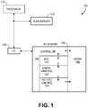
- Fig. 1shows a system containing a solid state non-volatile memory, according to an embodiment of the invention.
- the illustrated system 100comprises a processor 110, a main memory 120, input-output logic 130, and a non-volatile (NV) memory 140.
- the NV memoryis attached as an I/O device (such as but not limited to a solid-state disk), but other embodiments may place the NV memory elsewhere in the system, such as but not limited to a part of the main memory itself, a cache memory working in cooperation a hard disk drive, etc.
- I/O devicesuch as but not limited to a solid-state disk
- Various embodiments of the inventionshould be usable in diverse applications, and in different parts of a system, whether or not those applications and parts are specifically described here.
- the NV memorymay employ any feasible type of NV storage technology that uses stored charge to store data, and uses one or more reference voltages for read operations. It may be particularly useful in NV memory that reads an entire range of sequential memory locations with a single read command (such as but not limited to reading a page of memory from a NAND flash memory array), rather than reading an individual byte or word with a single read command.
- NV memory 140may comprise a storage array 148 and a controller 142 to control operations with the array such as read, write, erase, and adjustment of reference voltages.
- the controller 142may be further separated into other functional units, such as error checking and correction (ECC) unit 143, error analysis unit 144, and reference voltage control unit 145.
- ECCerror checking and correction
- the reference voltage control unit 145may provide each of the one or more reference voltages used when reading data from the memory cells in the array.
- the reference voltage control unit 145may also adjust these reference voltages up and/or down as needed to perform the operations described herein.
- the various units in NV memory 140are shown as separate functional units, two or more of them may share common circuitry and/or code.
- the controller 142may initiate an operation that reads data from multiple sequential locations in the memory array.
- the starting address of the locationsmay be indicated by the read request, while the number of locations may be specified in the request or may be predefined in some other manner.
- the ECC unitmay detect errors in the data, keep track of those errors, and correct the errors that it is able to correct through its error-correction algorithm.
- the data from an entire range of sequential addressese.g., a page or a sector of memory
- the data from an entire range of sequential addressesmay be designated as being incorrect, since the quantity and location of the uncorrectable errors within that range are unknown.
- Fig. 2shows a portion of a non-volatile memory array, according to an embodiment of the invention.
- the illustrated exampleshows a common representation of a flash memory array, in which each transistor represents a memory cell in which the amount of stored charge near the gate represents the data stored in that cell.
- Types of memory other than flash memory, and circuits other than the one shown,may also be included in the various embodiments of the invention.
- each of the horizontal linesrepresents a word line connecting the gates of multiple cells in that row (in this example approximately 32 thousand cells, but that number may differ in other embodiments), while the cells in each bit line column are connected to each of the adjacent cells in that column.
- the cellsmay represent single level cell (SLC) or multilevel cell (MLC) technology.
- SLCrefers to technology that stores only one bit per cell
- MLCrefers to technology that stores two or more bits per cell.
- the illustrated arrayrepresents a four-level MLC technology, where the range of possible charge is divided into four sub-ranges, labeled L0 through L3, and each sub-range represents a different 2-bit combination (e.g., 11, 10, 00, or 01). If the charge in a particular cell falls within one of those four sub-ranges, the cell is considered to be storing the corresponding 2-bit binary value.
- Example values for 15 of the cellsare given, with an unknown charge Vt on a 16 th cell.
- Fig. 3shows a flow diagram of a method of correcting errors in a memory, according to an embodiment of the invention.
- operations 310, 314, 318 and operations 311,315represent two different ways to identify low confidence (LC) cells in a page of data that is considered failed.
- Operations 320, 324, 328 and operation 321represent two different ways to attempt to correct the data in those LC cells.
- the verification operation at 330may be the same, regardless of which combination of identification and correction processes are used.
- the amount of charge stored in each cellmay be affected by the amount of charge stored in the surrounding cells, pulling that charge up or down from what it was intended to be.
- the cell with a charge level of Vtis the 'target' cell being investigated by examining the possible effect of the surrounding cells on Vt. Arrows indicate an example of the possible cells whose charge level might affect the charge Vt because of their physical proximity or electrical connection to the target cell.
- Fig. 4shows an example charge pattern that may affect a target cell, according to an embodiment of the invention.
- a 'pattern'is a group of cells with a predefined physical arrangement, with predefined electrical connections to each other, and predefined charge levels within those cells.
- a target cellis a cell that occupies a predefined place within the physical arrangement, and also is the cell that is being examined to determine the possible effect of other cells in the pattern upon it.
- a particular patternmay be defined based on the charge levels in all the cells in the pattern, including the charge level in the target cell. For example, in Fig.
- the cells on both sides of the target cellhave a charge level of L3, while the cells immediately above and below the target cell (adjacent cells on the same bit line) have charge level of L2.
- the correct charge level in the target cellis supposed to be L0, these surrounding cells might pull that charge in the target cell to an L1 level (as shown), and so having a charge of L1 in the target cell is part of this pattern.
- the charge level in the target cellis supposed to be L2 or L3
- the charge in the surrounding cellsmay be close enough to that level that they have little affect on it, and so that arrangement would not be considered a predefined pattern to be searched for.
- the charge level for any given cell in the patternmight cover more than one level.
- any of the four cells adjacent to the target cellmight be allowed to have a charge level of either L2 or L3, and that would still be considered as matching the pattern.
- This exampleshows a simple five-cell pattern (the target cell and the adjacent cells on the same word line and bit line) with a specific charge distribution, but other patterns may involve different arrangements of cells around the target cell and/or different quantities of cells and/or different charge distribution in the cells.
- the same set of patternsmay be expected to apply to large portions of the array, some patterns may be applicable only to specific portions of the array (e.g., a target cell at the edge of the array would have no adjacent cell on one side, so a different set of patterns might be used for cells at the edge). Because each cell might be examined separately with this pattern-matching technique, a given cell might be considered a target cell in one instance, but be one of the surrounding cells when another cell is being targeted.
- Fig. 5shows a flow diagram of a method of pattern-matching to identify low-confidence cells in a NV memory array, according to an embodiment of the invention.
- a particular page of data in the memoryhas one or more errors that were uncorrectable by the ECC unit, and that these errors were at least partly caused by the type of charge distribution effects previously described, so that the correct data may be determined by analyzing that charge distribution.
- an entire pageis considered failed because the ECC unit could not correct all the errors in that page, but units other than a page (e.g., a sector) may also be examined in this manner if the ECC code block size renders the failed unit a different size than a page.
- the binary data in the entire erase block containing the failed pagemay be read.
- the entire pageis considered 'failed', (because it is known to have errors but the locations of the errors within the page are unknown), it is still possible to read data from all cells in the page, even though some of that data will be incorrect. It may be desirable to read the entire erase block, rather than just the failed page, because of the way that NV memories are typically laid out, which permits cells in the correctly-read pages in the erase block to affect cells in the failed page in the same erase block.
- the binary data read from the erase blockmay be converted to charge level values.
- the exact manner of this conversionmay depend on how many charge levels (and therefore how many bits of binary data) are contained in each cell, and on how each of those levels indicates a particular binary data value.
- the results of this conversionmay be placed into a charge level map that contains the charge level value for each cell in the erase block.
- the mapmay also indicate (e.g., through the organization of the map) how those cells relate to each other, physically and/or electrically, so that they may be grouped together into groups that are meaningful for the subsequent pattern-matching process.
- One such manner of organizationthough not the only manner, is to organize the map into a two-dimensional array that reflects the row and column electrical layout of the cells in the erase block.
- each cell that is a target cell in a matched patternmay be designated a low-confidence cell at 540. Not all cells in the erase block need to be examined for patterns that have that cell as the target cell. Only groups of cells in which the target cell is in the failed page need to be examined for pattern matching. Since pages are frequently assigned to alternating bit lines, this may simplify the pattern matching process. Referring to Fig. 4 , the center bit line is in the failed page, but the bit lines to the left and right are in another page which the ECC has shown to contain correct data. So pattern matching does not need to be applied to groups of cells in which the target cell is not in the failed page. This also reduces the chances that another cell in the pattern (other than the target cell) contains incorrect data, since in this example only those cells on the same bit line as the target cell are in the failed page.
- This processcorresponds to operations 311,315 of Fig. 3 .
- the analog value of the charge stored in a cellis very close to the reference voltage that is used when reading that cell, it is very easy for the voltage of the charge to end up on the wrong side of that reference voltage and produce an incorrect reading.
- the process of Fig. 6takes advantage of this phenomenon.
- Fig. 6shows a flow diagram of a method of using proximity to a reference voltage as a way to identify low-confidence cells in a NV memory array, according to an embodiment of the invention.
- a process referred to herein as a 'moving read reference' (MRR)may be used to measure the analog charge voltage in each cell.
- each read reference voltagemay be incremented through a range of values. This incremental process may repeatedly cycle through operations 610-650 until the MRR process is complete, as determined at 620. Any feasible technique may be used to increment the reference voltage(s).
- some embodimentsmay increment only a single reference voltage for each new cycle, while other embodiments may increment multiple reference voltages for each new cycle. Some embodiments may increment all the reference voltages for each new cycle. Some embodiments may switch between these alternatives on difference cycles.
- the binary value of data stored in each cell in the failed pagemay be read at 630. If the data read from a given cell is different than it was in the previous pass, as indicated at 640, that indicates that the incremented reference voltage has just crossed over the analog charge value, and the analog charge value must be very close to the reference voltage (within the range of one increment). This value may then be recorded at 650 in a map of analog charge values. This may be performed for every cell that shows changed data from the previous pass. In MLC memories that have multiple reference voltages, the particular before-and-after binary values may need to be examined to determine which reference voltage was crossed, so the proper voltage may be recorded. The process of 610-650 may be repeated until the analog charge values for all the cells in the failed page have been recorded.
- the unrecorded cellsmay have an analog charge value that is outside the tested ranges (in which case the ranges may be expanded for further testing), or the cell has failed completely (in which case other corrective actions, not described here, may be taken). Assuming that all the cells have recorded values, the process may move from operation 620 to operation 660, where the reference voltages may be restored to their original values so that normal read operations may take place.
- the analog charge value that was recorded for each cellmay be compared to the restored reference voltages at 670. (The restored values of the reference voltages may be recorded, and the recorded values used in this comparison, so that further accesses to the actual cells will not be necessary.) If any cell has an analog charge value that is close to a restored reference voltage, that cell may be identified at 680 as a low confidence cell. Just how close the analog charge value needs to be to a reference voltage before it is considered 'low confidence' may depend on various factors. In some embodiments the range of analog charge values that are considered 'close' to the reference voltage, and/or the center point of this range, may be changed during processing. For example, a fairly narrow range of voltages may be used at first. If this does not produce satisfactory results, the range may be enlarged in an attempt to include more cells in the 'low confidence' category. Several iterations of these changes may be made before satisfactory results are obtained.
- This processcorresponds with operations 320, 324, 328 of Fig. 3 .
- itinvolves adjusting the analog charge value of a low confidence cell in a manner that is projected to improve the likelihood of getting correct data from the cell.
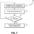
- Fig. 7shows a flow diagram of a method of correcting data in a NV memory through adjustment of analog charge values, according to an embodiment of the invention.
- the starting values of those analog charge valuesmust be known. If the MRR process of operations 610-650 in Fig. 6 has already been performed to identify low confidence cells, then those starting values are already known. If it has not, the MRR process may be performed before starting the method of flow diagram 700.
- the amount (change the amount of charge, which changes the analog charge value), and the direction (add or subtract charge) of the projected adjustment to the cellmay be determined. Any feasible method may be used to determine the direction and amount of this adjustment.
- this adjustmentmay be made to the analog charge value. Rather than changing the actual charge that exists in the physical cell, this process may be performed mathematically on the recorded analog charge values in the analog charge map that was previously constructed for the failed page.
- the number of low confidence cells to adjust in this manner before performing a verificationmay depend on numerous factors. Adjusting all the low confidence cells (or at least a large number of cells) runs the risk of changing previously correct data into bad data, potentially making the problem worse. Adjusting a small number of cells before verification runs the risk of not changing enough bad cells to get a valid ECC result during verification, and thus not knowing if the changes were correct or not. However the number of cells to change might be determined, after that number of cells has been changed, as determined at 730, the process may move to 740 where the new analog charge values for the low confidence cells are converted into their equivalent binary data.
- This processcorresponds with operation 321 of Fig. 3 .
- itinvolves trying random data in the low confidence cells, until a combination is found that produces a page with so few errors that the errors can be corrected through other means, such as with an ECC process.
- the number of cells to change in this manner before attempting verificationmay vary.
- the preferred number of cells to changemay depend on various factors, such as but not limited to: 1) which correction technique is being used, 2) the number of cells contained in the failed address range, 3) etc.
- Verificationcorresponds with operation 330 of Fig. 3 .
- Verification of the data in the pagemay be performed through any feasible manner, such as but not limited to processing the page of binary data through an ECC process that will correct the remaining errors, provided the quantify of errors is not beyond the ability of the ECC to correct. If the corrected data is verified in this manner, the corrected data may be written to a storage location where it can be used. This would presumably not be to the same page in the same erase block in which it originally failed, since defects in that physical storage location may have caused the errors in the first place.
- various proceduresmay be followed, such as but not limited to one or more of: 1) assume the data in the page is lost, and discard the data, 2) re-run the previous operations on the new or original data, but use different parameters to correct the data, 3) re-run the previous operations on different low confidence cells, 4) run different detection operations to determine the low confidence cells, 5) etc.
- these operationsmay be performed within the controller of the NV memory (e.g., by the error analysis unit 144 of Fig. 1 ). In other embodiments these operations may be performed external to the NV memory (e.g., by one or more main processors in the computer system). In still other embodiments these operations may be performed by multiple such devices (e.g., some operations in the NV memory controller, some operations by the main processor(s). These are only a few of the ways in which the operations may be performed.
Landscapes
- Engineering & Computer Science (AREA)
- Theoretical Computer Science (AREA)
- Physics & Mathematics (AREA)
- General Engineering & Computer Science (AREA)
- General Physics & Mathematics (AREA)
- Quality & Reliability (AREA)
- Read Only Memory (AREA)
- Techniques For Improving Reliability Of Storages (AREA)
- For Increasing The Reliability Of Semiconductor Memories (AREA)
- Detection And Correction Of Errors (AREA)
Description
- Some types of solid state non- volatile memory, such as flash memory, record binary data by storing a certain amount of electrical charge in a memory cell. When the data is read from one of these charge-based non- volatile memories, the voltage level of the stored charge is compared to a reference voltage. The binary value of the data read from that cell depends on whether the voltage of the stored charge is higher or lower than the reference voltage. However, since the stored charge is an analog phenomenon, its actual value may not be exactly what was intended, and errors may be encountered when the data is read. Error correcting code (ECC) units may be used to detect and correct some of these .errors, but sometimes the errors are too numerous to all be corrected in this manner. When this happens, the data may be permanently lost.
US 6,542,407 discloses techniques of overcoming degradation of apparent charge levels in a row of memory cells caused by subsequently programming an adjacent row, which includes driving the charge levels of the cells to a common level which increases the chance of successfully reading the data.US 2008/0123419 discloses a method including adjusting programming target voltages and read voltages together over memory life to map memory states to an increasingly wide threshold window, thus reducing errors.- Aspects of the present invention are defined by the independent claims appended hereto.
- Some embodiments of the invention may be understood by referring to the following description and accompanying drawings that are used to illustrate embodiments of the invention. In the drawings:
Fig. 1 shows a system containing a solid state non-volatile memory, according to an embodiment of the invention.Fig. 2 shows a portion of a non- volatile memory array, according to an embodiment of the invention.Fig. 3 shows a flow diagram of a method of correcting errors in a memory, according to an embodiment of the invention.Fig. 4 shows an example charge pattern that may affect a target cell, according to an embodiment of the invention.Fig. 5 shows a flow diagram of a method of pattern-matching to identify low- confidence cells in a NV memory array, according to an embodiment of the invention.Fig. 6 shows a flow diagram of a method of using proximity to reference voltages as a way to identify low-confidence cells in a NV memory array, according to an embodiment of the invention.Fig. 7 shows a flow diagram of a method of correcting data in a NV memory through adjustment of analog charge values, according to an embodiment of the invention.- In the following description, numerous specific details are set forth. However, it is understood that embodiments of the invention may be practiced without these specific details. In other instances, well-known circuits, structures and techniques have not been shown in detail in order not to obscure an understanding of this description.
- References to "one embodiment", "an embodiment", "example embodiment", "various embodiments", etc., indicate that the embodiment(s) of the invention so described may include particular features, structures, or characteristics, but not every embodiment necessarily includes the particular features, structures, or characteristics. Further, some embodiments may have some, all, or none of the features described for other embodiments.
- In the following description and claims, the terms "coupled" and "connected," along with their derivatives, may be used. It should be understood that these terms are not intended as synonyms for each other. Rather, in particular embodiments, "connected" is used to indicate that two or more elements are in direct physical or electrical contact with each other. "Coupled" is used to indicate that two or more elements co-operate or interact with each other, but they may or may not be in direct physical or electrical contact.
- As used in the claims, unless otherwise specified the use of the ordinal adjectives "first", "second", "third", etc., to describe a common element, merely indicate that different instances of like elements are being referred to, and are not intended to imply that the elements so described must be in a given sequence, either temporally, spatially, in ranking, or in any other manner.
- Various embodiments of the invention may be implemented in one or any combination of hardware, firmware, and software. The invention may also be implemented as instructions contained in or on a computer-readable medium, which may be read and executed by one or more processors to enable performance of the operations described herein. A computer-readable medium may include any mechanism for storing, transmitting, and/or receiving information in a form readable by one or more computers. For example, a computer-readable medium may include a tangible storage medium, such as but not limited to read only memory (ROM); random access memory (RAM); magnetic disk storage media; optical storage media; a flash memory device, etc. A computer-readable medium may also include a propagated signal which has been modulated to encode the instructions, such as but not limited to electromagnetic, optical, or acoustical carrier wave signals.
- In various embodiments, if uncorrectable errors are found when reading data from a portion of charge-based non-volatile memory, a process may be followed to attempt to correct the data. Since the exact location of the bad data may not be known, this process may comprise 1) identifying 'low confidence' (LC) storage cells in that portion of memory (i.e., cells that are more likely than other cells to contains errors), 2) determining what data in those cells is likely to be correct, and 3) verifying that the new data is correct. Identifying low confidence cells may be done in either of two ways: 1) find cells whose analog charge voltage is close to a reference voltage, or 2) look for particular patterns of charge levels in the surrounding cells that are known to cause data corruption in a target cell. Determining new data that is likely to be correct in the low confidence cells may be done in either of two ways: 1) adjust the analog charge value in those cells in a direction and amount that seems best, or 2) try random values of data in the LC cells. Verifying that the new data is correct may be performed in any suitable manner, but may typically be done by using an error checking and correction (ECC) algorithm, since this will produce valid data as long as the number of errors is below a certain threshold. Once the correct values of the data have been determined, the data may be re-written to another location, where it hopefully will not experience the same problems of data corruption. Although computationally intensive, this process may be useful for recovering data that is otherwise impractical to recover in other ways, such as data in a solid state disc (SSD) that contains fatal errors in important data.
Fig. 1 shows a system containing a solid state non-volatile memory, according to an embodiment of the invention. The illustratedsystem 100 comprises aprocessor 110, amain memory 120, input-output logic 130, and a non-volatile (NV)memory 140. In this particular implementation, the NV memory is attached as an I/O device (such as but not limited to a solid-state disk), but other embodiments may place the NV memory elsewhere in the system, such as but not limited to a part of the main memory itself, a cache memory working in cooperation a hard disk drive, etc. Various embodiments of the invention should be usable in diverse applications, and in different parts of a system, whether or not those applications and parts are specifically described here.- The NV memory may employ any feasible type of NV storage technology that uses stored charge to store data, and uses one or more reference voltages for read operations. It may be particularly useful in NV memory that reads an entire range of sequential memory locations with a single read command (such as but not limited to reading a page of memory from a NAND flash memory array), rather than reading an individual byte or word with a single read command.
- In the illustrated embodiment of
Fig. 1 ,NV memory 140 may comprise astorage array 148 and acontroller 142 to control operations with the array such as read, write, erase, and adjustment of reference voltages. Thecontroller 142 may be further separated into other functional units, such as error checking and correction (ECC)unit 143,error analysis unit 144, and referencevoltage control unit 145. The referencevoltage control unit 145 may provide each of the one or more reference voltages used when reading data from the memory cells in the array. The referencevoltage control unit 145 may also adjust these reference voltages up and/or down as needed to perform the operations described herein. Although the various units inNV memory 140 are shown as separate functional units, two or more of them may share common circuitry and/or code. - Whenever the
controller 142 receives a read request from theprocessor 110 or other device, thecontroller 142 may initiate an operation that reads data from multiple sequential locations in the memory array. The starting address of the locations may be indicated by the read request, while the number of locations may be specified in the request or may be predefined in some other manner. As the data is read and placed in a buffer, the ECC unit may detect errors in the data, keep track of those errors, and correct the errors that it is able to correct through its error-correction algorithm. When non-correctable errors (i.e., not correctable by the ECC unit) are detected in this manner, the data from an entire range of sequential addresses (e.g., a page or a sector of memory) may be designated as being incorrect, since the quantity and location of the uncorrectable errors within that range are unknown. Fig. 2 shows a portion of a non-volatile memory array, according to an embodiment of the invention. The illustrated example shows a common representation of a flash memory array, in which each transistor represents a memory cell in which the amount of stored charge near the gate represents the data stored in that cell. Types of memory other than flash memory, and circuits other than the one shown, may also be included in the various embodiments of the invention. In the particular example shown, each of the horizontal lines represents a word line connecting the gates of multiple cells in that row (in this example approximately 32 thousand cells, but that number may differ in other embodiments), while the cells in each bit line column are connected to each of the adjacent cells in that column. The cells may represent single level cell (SLC) or multilevel cell (MLC) technology. As the terms are used in this document, SLC refers to technology that stores only one bit per cell, while MLC refers to technology that stores two or more bits per cell. The illustrated array represents a four-level MLC technology, where the range of possible charge is divided into four sub-ranges, labeled L0 through L3, and each sub-range represents a different 2-bit combination (e.g., 11, 10, 00, or 01). If the charge in a particular cell falls within one of those four sub-ranges, the cell is considered to be storing the corresponding 2-bit binary value. Example values for 15 of the cells are given, with an unknown charge Vt on a 16th cell.- For the following discussions, it is assumed that an ECC or other type of error detection and correction algorithm has been used, but it cannot correct all the errors in a given range of sequential memory addresses. In such cases, it is known that the errors are contained within this range, but it is not known exactly which addresses (and therefore which cells) contain the errors. In many cases it is not known how many errors there are, except that the number of errors exceeds the ability of the ECC to correct them all. For this discussion, it is assumed that the entire page is considered to be 'failed' because the ECC unit could not correct all the errors in that page, but units other than a page (e.g., a sector) may also be examined in this manner if the ECC code block size renders the failed unit a different size than a page. The following definitions are used in this document:
- 1)analog charge value - a value that represents the voltage for the charge stored in a particular cell. Although this value may be expressed as a discrete digital or binary number for processing, it represents the analog charge value and is therefore labeled as an analog value.
- 2)charge level value - a value that represents one of the sub-ranges of charge level in the cell, in which each sub-range represents a different binary data value. For example, in a four-level MLC, a charge level value of 0 may represent the lowest sub-range (least amount of charge), 1 the next higher sub-range, 2 the next higher sub-range, and 3 the highest sub-range (greatest amount of charge).
- 3)binary data value - the binary value of the data that is being stored in a cell. For example, in a four-level MLC, a binary 11 may be represented by charge level value of 0, a binary 10 may be represented by a charge level value of 1, a binary 00 may be represented by a charge level value of 2, and a binary 01 may be represented by a charge level value of 3. These particular conversion values may be advantageous because a transition from one charge level to the next only changes one bit of the equivalent binary value, reducing the uncertainly of a borderline reading to only two possibilities. However, other conversion values may also be used.
Fig. 3 shows a flow diagram of a method of correcting errors in a memory, according to an embodiment of the invention. In flow diagram 300,operations Operations operation 321 represent two different ways to attempt to correct the data in those LC cells. The verification operation at 330 may be the same, regardless of which combination of identification and correction processes are used.- This process corresponds with
operations Fig. 3 . With the ever-smaller geometries used in memory arrays, the amount of charge stored in each cell may be affected by the amount of charge stored in the surrounding cells, pulling that charge up or down from what it was intended to be. Referring back toFig. 2 for an example, the cell with a charge level of Vt is the 'target' cell being investigated by examining the possible effect of the surrounding cells on Vt. Arrows indicate an example of the possible cells whose charge level might affect the charge Vt because of their physical proximity or electrical connection to the target cell. The exact nature of this effect, and the particular cells that might cause it, may depend on the specifics of the array, such as physical closeness of the cells, the cell structure, the semiconductor materials used, the actual charge level in each of the surrounding cells and in the target cell, etc. Such interrelationships may be determined for each type of array, and for each pattern of charge distribution in the cells. Fig. 4 shows an example charge pattern that may affect a target cell, according to an embodiment of the invention. For the purposes of this document, a 'pattern' is a group of cells with a predefined physical arrangement, with predefined electrical connections to each other, and predefined charge levels within those cells. A target cell is a cell that occupies a predefined place within the physical arrangement, and also is the cell that is being examined to determine the possible effect of other cells in the pattern upon it. A particular pattern may be defined based on the charge levels in all the cells in the pattern, including the charge level in the target cell. For example, inFig. 4 the cells on both sides of the target cell (adjacent cells on the same word line) have a charge level of L3, while the cells immediately above and below the target cell (adjacent cells on the same bit line) have charge level of L2. If the correct charge level in the target cell is supposed to be L0, these surrounding cells might pull that charge in the target cell to an L1 level (as shown), and so having a charge of L1 in the target cell is part of this pattern. On the other hand, if the charge level in the target cell is supposed to be L2 or L3, the charge in the surrounding cells may be close enough to that level that they have little affect on it, and so that arrangement would not be considered a predefined pattern to be searched for. In some embodiments, the charge level for any given cell in the pattern might cover more than one level. Using the pattern ofFig. 4 as an example, any of the four cells adjacent to the target cell might be allowed to have a charge level of either L2 or L3, and that would still be considered as matching the pattern.- This example shows a simple five-cell pattern (the target cell and the adjacent cells on the same word line and bit line) with a specific charge distribution, but other patterns may involve different arrangements of cells around the target cell and/or different quantities of cells and/or different charge distribution in the cells. Although the same set of patterns may be expected to apply to large portions of the array, some patterns may be applicable only to specific portions of the array (e.g., a target cell at the edge of the array would have no adjacent cell on one side, so a different set of patterns might be used for cells at the edge). Because each cell might be examined separately with this pattern-matching technique, a given cell might be considered a target cell in one instance, but be one of the surrounding cells when another cell is being targeted.
Fig. 5 shows a flow diagram of a method of pattern-matching to identify low-confidence cells in a NV memory array, according to an embodiment of the invention. In the described method, it is assumed that a particular page of data in the memory has one or more errors that were uncorrectable by the ECC unit, and that these errors were at least partly caused by the type of charge distribution effects previously described, so that the correct data may be determined by analyzing that charge distribution. For this discussion, it is assumed that an entire page is considered failed because the ECC unit could not correct all the errors in that page, but units other than a page (e.g., a sector) may also be examined in this manner if the ECC code block size renders the failed unit a different size than a page.- In the illustrated flow diagram 500, at 510 the binary data in the entire erase block containing the failed page may be read. Although the entire page is considered 'failed', (because it is known to have errors but the locations of the errors within the page are unknown), it is still possible to read data from all cells in the page, even though some of that data will be incorrect. It may be desirable to read the entire erase block, rather than just the failed page, because of the way that NV memories are typically laid out, which permits cells in the correctly-read pages in the erase block to affect cells in the failed page in the same erase block.
- At 520, the binary data read from the erase block may be converted to charge level values. The exact manner of this conversion may depend on how many charge levels (and therefore how many bits of binary data) are contained in each cell, and on how each of those levels indicates a particular binary data value. The results of this conversion may be placed into a charge level map that contains the charge level value for each cell in the erase block. The map may also indicate (e.g., through the organization of the map) how those cells relate to each other, physically and/or electrically, so that they may be grouped together into groups that are meaningful for the subsequent pattern-matching process. One such manner of organization, though not the only manner, is to organize the map into a two-dimensional array that reflects the row and column electrical layout of the cells in the erase block.
- At 530 the actual pattern-matching process may be done. The earlier description of
Fig. 4 provides one example of this pattern-matching process. Each cell that is a target cell in a matched pattern may be designated a low-confidence cell at 540. Not all cells in the erase block need to be examined for patterns that have that cell as the target cell. Only groups of cells in which the target cell is in the failed page need to be examined for pattern matching. Since pages are frequently assigned to alternating bit lines, this may simplify the pattern matching process. Referring toFig. 4 , the center bit line is in the failed page, but the bit lines to the left and right are in another page which the ECC has shown to contain correct data. So pattern matching does not need to be applied to groups of cells in which the target cell is not in the failed page. This also reduces the chances that another cell in the pattern (other than the target cell) contains incorrect data, since in this example only those cells on the same bit line as the target cell are in the failed page. - This process corresponds to operations 311,315 of
Fig. 3 . When the analog value of the charge stored in a cell is very close to the reference voltage that is used when reading that cell, it is very easy for the voltage of the charge to end up on the wrong side of that reference voltage and produce an incorrect reading. The process ofFig. 6 takes advantage of this phenomenon. Fig. 6 shows a flow diagram of a method of using proximity to a reference voltage as a way to identify low-confidence cells in a NV memory array, according to an embodiment of the invention. In flow diagram 600, a process referred to herein as a 'moving read reference' (MRR) may be used to measure the analog charge voltage in each cell. At 610, each read reference voltage may be incremented through a range of values. This incremental process may repeatedly cycle through operations 610-650 until the MRR process is complete, as determined at 620. Any feasible technique may be used to increment the reference voltage(s). For multi-level cell technology, in which there are multiple reference voltages, some embodiments may increment only a single reference voltage for each new cycle, while other embodiments may increment multiple reference voltages for each new cycle. Some embodiments may increment all the reference voltages for each new cycle. Some embodiments may switch between these alternatives on difference cycles.- After each increment, the binary value of data stored in each cell in the failed page may be read at 630. If the data read from a given cell is different than it was in the previous pass, as indicated at 640, that indicates that the incremented reference voltage has just crossed over the analog charge value, and the analog charge value must be very close to the reference voltage (within the range of one increment). This value may then be recorded at 650 in a map of analog charge values. This may be performed for every cell that shows changed data from the previous pass. In MLC memories that have multiple reference voltages, the particular before-and-after binary values may need to be examined to determine which reference voltage was crossed, so the proper voltage may be recorded. The process of 610-650 may be repeated until the analog charge values for all the cells in the failed page have been recorded.
- If all the incremented values of the reference voltages have been tried, but not all the cells in the page have a recorded value for their analog charge, then the unrecorded cells may have an analog charge value that is outside the tested ranges (in which case the ranges may be expanded for further testing), or the cell has failed completely (in which case other corrective actions, not described here, may be taken). Assuming that all the cells have recorded values, the process may move from
operation 620 tooperation 660, where the reference voltages may be restored to their original values so that normal read operations may take place. - At this point, the analog charge value that was recorded for each cell may be compared to the restored reference voltages at 670. (The restored values of the reference voltages may be recorded, and the recorded values used in this comparison, so that further accesses to the actual cells will not be necessary.) If any cell has an analog charge value that is close to a restored reference voltage, that cell may be identified at 680 as a low confidence cell. Just how close the analog charge value needs to be to a reference voltage before it is considered 'low confidence' may depend on various factors. In some embodiments the range of analog charge values that are considered 'close' to the reference voltage, and/or the center point of this range, may be changed during processing. For example, a fairly narrow range of voltages may be used at first. If this does not produce satisfactory results, the range may be enlarged in an attempt to include more cells in the 'low confidence' category. Several iterations of these changes may be made before satisfactory results are obtained.
- This process corresponds with
operations Fig. 3 . In general, it involves adjusting the analog charge value of a low confidence cell in a manner that is projected to improve the likelihood of getting correct data from the cell. Fig. 7 shows a flow diagram of a method of correcting data in a NV memory through adjustment of analog charge values, according to an embodiment of the invention. To adjust analog charge values for low-confidence cells in the failed page, the starting values of those analog charge values must be known. If the MRR process of operations 610-650 inFig. 6 has already been performed to identify low confidence cells, then those starting values are already known. If it has not, the MRR process may be performed before starting the method of flow diagram 700.- For each low-confidence cell, at 710 the amount (change the amount of charge, which changes the analog charge value), and the direction (add or subtract charge) of the projected adjustment to the cell may be determined. Any feasible method may be used to determine the direction and amount of this adjustment. At 720, this adjustment may be made to the analog charge value. Rather than changing the actual charge that exists in the physical cell, this process may be performed mathematically on the recorded analog charge values in the analog charge map that was previously constructed for the failed page.
- The number of low confidence cells to adjust in this manner before performing a verification may depend on numerous factors. Adjusting all the low confidence cells (or at least a large number of cells) runs the risk of changing previously correct data into bad data, potentially making the problem worse. Adjusting a small number of cells before verification runs the risk of not changing enough bad cells to get a valid ECC result during verification, and thus not knowing if the changes were correct or not. However the number of cells to change might be determined, after that number of cells has been changed, as determined at 730, the process may move to 740 where the new analog charge values for the low confidence cells are converted into their equivalent binary data.
- This process corresponds with
operation 321 ofFig. 3 . In general, it involves trying random data in the low confidence cells, until a combination is found that produces a page with so few errors that the errors can be corrected through other means, such as with an ECC process. As described for the process ofFig. 7 , the number of cells to change in this manner before attempting verification may vary. In some embodiments, the preferred number of cells to change may depend on various factors, such as but not limited to: 1) which correction technique is being used, 2) the number of cells contained in the failed address range, 3) etc. - Verification corresponds with
operation 330 ofFig. 3 . Verification of the data in the page may be performed through any feasible manner, such as but not limited to processing the page of binary data through an ECC process that will correct the remaining errors, provided the quantify of errors is not beyond the ability of the ECC to correct. If the corrected data is verified in this manner, the corrected data may be written to a storage location where it can be used. This would presumably not be to the same page in the same erase block in which it originally failed, since defects in that physical storage location may have caused the errors in the first place. On the other hand, if the new page of data still has uncorrectable errors, various procedures may be followed, such as but not limited to one or more of: 1) assume the data in the page is lost, and discard the data, 2) re-run the previous operations on the new or original data, but use different parameters to correct the data, 3) re-run the previous operations on different low confidence cells, 4) run different detection operations to determine the low confidence cells, 5) etc. - In some embodiments these operations may be performed within the controller of the NV memory (e.g., by the
error analysis unit 144 ofFig. 1 ). In other embodiments these operations may be performed external to the NV memory (e.g., by one or more main processors in the computer system). In still other embodiments these operations may be performed by multiple such devices (e.g., some operations in the NV memory controller, some operations by the main processor(s). These are only a few of the ways in which the operations may be performed. - The foregoing description is intended to be illustrative and not limiting. Variations will occur to those of skill in the art. Those variations are intended to be included in the various embodiments of the invention, which are limited only by the scope of the following claims.
Claims (11)
- A method for data error recovery in non-volatile memory, comprising:determining that binary data read from a specified range of sequential memory locations in a charge-based non-volatile (NV) memory array (148) contains errors that were uncorrected by an error correcting code (ECC) unit (143) associated with the NV memory array, wherein the specified range of sequential memory locations is a page of memory;identifying which memory cells in the specified range produced data that is likely to be in error;changing the data for at least some of the memory cells whose data was determined to likely be in error; andverifying whether the changed data enables the ECC unit to correct the previously uncorrected errors in the specified range of sequential memory locations;characterised in that the identifying includes:incrementing a read reference voltage through a range of voltage values (610); andreading for each increment, binary data from within the specified range of sequential memory locations (630); and the method further includes:identifying which memory cells produce different binary data in a current increment than for a previous increment to determine analog charge values for the memory cells that produced different binary data, (640,650), wherein the analog charge value is a value that represents the voltage for the charge stored in a particular cell;restoring the incremented read reference voltage (660) to their original read reference voltages; andcomparing the restored incremented read reference voltage to the analog charge vlaues for the memory cells that produced different binary data to identify which memory cells in the specified range produced data that is likely to be in error (670,680).
- The method of claim 1, wherein said identifying comprises:producing a map of charge level values for the memory cells in at least the specified range (650); andcomparing the charge level values in groups of memory cells in the map to predefined patterns of charge levels, to identify which of the memory cells produced binary data likely to be in error.
- The method of claim 1, wherein said identifying comprises:determining analog charge values for memory cells in the specified range; anddetermining which memory cells in the specified range have an analog charge value within a predetermined voltage amount of a read reference voltage for the NV memory array.
- The method of claim 1, wherein said changing comprises adjusting analog charge values for the memory cells identified as likely to be in error.
- The method of claim 1, wherein said changing comprises substituting random binary data for the data from the memory cells identified as likely to be in error.
- An apparatus, comprising:a computer system (100) containing a processor (110) and a charge-based non-volatile (NV) memory array (148), the computer system being operable to perform data error recovery in the memory array by:verifying whether the changed data enables the ECC unit to correct the previously uncorrected errors in the specified range of sequential memory locations,determining that binary data read from a specified range of sequential memory locations in the NV memory array contains errors that were uncorrected by an error correcting code (ECC) unit (143) associated with the NV memory array, wherein the specified range of sequential memory locations is a page of memory for the NV memory array;identifying which memory cells in the specified range produced data that is likely to be in error;changing the data for at least some of the cells whose data was determined to likely be in error; and
characterized in that the identifying includes:incrementing a read reference voltage through a range of voltage values; and reading for each increment, binary data from within the specified range of sequential memory locations; and the data error recovery further includes:identifying which memory cells produce different binary data in a current increment than for a previous increment to determine analog charge values for the memory cells that produced different binary data, wherein the analog charge value is a value that represents the voltage for the charge stored in a particular cell; andrestoring the incremented read reference voltage to their original read reference voltage; andcomparing the restored incremented read reference voltage to the analog charge values for the memory cells that produced different binary data to identify which memory cells in the specified range produced data that is likely to be in error. - The apparatus of claim 6, wherein said identifying comprises:producing a map of charge level values for the memory cells in at least the specified range; andcomparing the charge level values in groups of memory cells in the map to predefined patterns of charge levels, to identify which of the memory cells produced binary data likely to be in error.
- The apparatus of claim 6, wherein said identifying comprises:determining analog charge values for memory cells in the specified range; anddetermining which memory cells in the specified range have an analog charge value within a predetermined voltage amount of a read reference voltage for the NV memory array.
- The apparatus of claim 6, wherein said changing comprises adjusting analog charge values for the memory cells identified as likely to be in error.
- The apparatus of claim 6, wherein said changing comprises substituting random binary data for the data from the memory cells identified as likely to be in error.
- An article comprising
a tangible computer-readable medium that contains instructions, which when executed by one or more processors result in performing the method of any one of claims 1 to 5.
Applications Claiming Priority (2)
| Application Number | Priority Date | Filing Date | Title |
|---|---|---|---|
| US12/316,986US8291297B2 (en) | 2008-12-18 | 2008-12-18 | Data error recovery in non-volatile memory |
| PCT/US2009/066612WO2010080257A2 (en) | 2008-12-18 | 2009-12-03 | Data error recovery in non-volatile memory |
Publications (3)
| Publication Number | Publication Date |
|---|---|
| EP2368186A2 EP2368186A2 (en) | 2011-09-28 |
| EP2368186A4 EP2368186A4 (en) | 2012-07-18 |
| EP2368186B1true EP2368186B1 (en) | 2017-07-26 |
Family
ID=42267898
Family Applications (1)
| Application Number | Title | Priority Date | Filing Date |
|---|---|---|---|
| EP09837801.1ANot-in-forceEP2368186B1 (en) | 2008-12-18 | 2009-12-03 | Data error recovery in non-volatile memory |
Country Status (7)
| Country | Link |
|---|---|
| US (1) | US8291297B2 (en) |
| EP (1) | EP2368186B1 (en) |
| JP (1) | JP5367835B2 (en) |
| KR (1) | KR101248352B1 (en) |
| CN (1) | CN102171659B (en) |
| TW (1) | TWI455145B (en) |
| WO (1) | WO2010080257A2 (en) |
Families Citing this family (32)
| Publication number | Priority date | Publication date | Assignee | Title |
|---|---|---|---|---|
| US8291297B2 (en) | 2008-12-18 | 2012-10-16 | Intel Corporation | Data error recovery in non-volatile memory |
| US8407564B2 (en)* | 2009-07-15 | 2013-03-26 | Intel Corporation | Prediction and cancellation of systematic noise sources in non-volatile memory |
| US8190974B2 (en)* | 2009-09-28 | 2012-05-29 | Nvidia Corporation | Error detection and correction for external DRAM |
| US8301980B2 (en)* | 2009-09-28 | 2012-10-30 | Nvidia Corporation | Error detection and correction for external DRAM |
| US8638602B1 (en) | 2010-09-10 | 2014-01-28 | Western Digital Technologies, Inc. | Background selection of voltage reference values for performing memory read operations |
| KR101736384B1 (en) | 2010-09-29 | 2017-05-16 | 삼성전자주식회사 | Nonvolatile Memory System |
| US8599609B2 (en) | 2010-12-22 | 2013-12-03 | HGST Netherlands B.V. | Data management in flash memory using probability of charge disturbances |
| US8422303B2 (en)* | 2010-12-22 | 2013-04-16 | HGST Netherlands B.V. | Early degradation detection in flash memory using test cells |
| US8369143B2 (en) | 2010-12-22 | 2013-02-05 | HGST Netherlands B.V. | Early detection of degradation in NOR flash memory |
| US8649215B2 (en) | 2010-12-22 | 2014-02-11 | HGST Netherlands B.V. | Data management in flash memory using probability of charge disturbances |
| US8422296B2 (en) | 2010-12-22 | 2013-04-16 | HGST Netherlands B.V. | Early detection of degradation in NAND flash memory |
| KR101739878B1 (en) | 2011-02-22 | 2017-05-26 | 삼성전자주식회사 | Controller, method of operating the controller, and memory system having the controller |
| US8503237B1 (en) | 2011-05-18 | 2013-08-06 | Western Digital Technologies, Inc. | System and method for data recovery in a solid state storage device |
| KR101835605B1 (en) | 2011-11-24 | 2018-03-08 | 삼성전자 주식회사 | Flash memory device and reading method of flash memory device |
| US9112537B2 (en)* | 2011-12-22 | 2015-08-18 | Intel Corporation | Content-aware caches for reliability |
| KR101625000B1 (en)* | 2012-03-29 | 2016-05-27 | 인텔 코포레이션 | Adaptive moving read references for memory cells |
| US9208022B2 (en)* | 2012-03-29 | 2015-12-08 | Intel Corporation | Techniques for adaptive moving read references for memory cell read error recovery |
| US8793558B2 (en)* | 2012-08-27 | 2014-07-29 | Freescale Semiconductor, Inc. | Adaptive error correction for non-volatile memories |
| US8869008B2 (en)* | 2013-01-17 | 2014-10-21 | Apple Inc. | Adaptation of analog memory cell read thresholds using partial ECC syndromes |
| US10114912B1 (en)* | 2014-03-26 | 2018-10-30 | Cadence Design Systems, Inc. | System and method for monitoring address traffic in an electronic design |
| KR102292167B1 (en)* | 2014-04-04 | 2021-08-25 | 삼성전자주식회사 | Method for managing bad block and memory system |
| US9389973B2 (en) | 2014-05-30 | 2016-07-12 | Oracle International Corporation | Memory error propagation for faster error recovery |
| US9558069B2 (en)* | 2014-08-07 | 2017-01-31 | Pure Storage, Inc. | Failure mapping in a storage array |
| CN104317525B (en)* | 2014-09-23 | 2017-08-11 | 天津国芯科技有限公司 | The extended method and device of a kind of random access memory |
| US9728278B2 (en)* | 2014-10-24 | 2017-08-08 | Micron Technology, Inc. | Threshold voltage margin analysis |
| KR20160073834A (en)* | 2014-12-17 | 2016-06-27 | 에스케이하이닉스 주식회사 | Semiconductor memory device and operating method thereof |
| US9679661B1 (en) | 2016-06-28 | 2017-06-13 | Sandisk Technologies Llc | Non-volatile storage system with self-test for read performance enhancement feature setup |
| US9672940B1 (en) | 2016-08-18 | 2017-06-06 | Sandisk Technologies Llc | Non-volatile memory with fast read process |
| KR20210132784A (en) | 2020-04-27 | 2021-11-05 | 삼성전자주식회사 | Memory device and method for reading data from memory device |
| US11409601B1 (en) | 2021-01-26 | 2022-08-09 | Micron Technology, Inc. | Memory device protection |
| US12346588B2 (en)* | 2023-03-28 | 2025-07-01 | Micron Technology, Inc. | Apparatus with memory cell calibration mechanism and methods for operating the same |
| KR102839313B1 (en) | 2024-11-29 | 2025-07-28 | 주식회사 더블오 | Apparatus for counting bad logical unit in onfi compliant nand flash memory |
Family Cites Families (39)
| Publication number | Priority date | Publication date | Assignee | Title |
|---|---|---|---|---|
| US6222762B1 (en)* | 1992-01-14 | 2001-04-24 | Sandisk Corporation | Multi-state memory |
| US5859858A (en)* | 1996-10-25 | 1999-01-12 | Intel Corporation | Method and apparatus for correcting a multilevel cell memory by using error locating codes |
| JP2001332096A (en)* | 2000-05-16 | 2001-11-30 | Hitachi Ltd | Nonvolatile semiconductor memory and recording / reproducing apparatus using nonvolatile semiconductor memory |
| JP4323707B2 (en)* | 2000-10-25 | 2009-09-02 | 富士通マイクロエレクトロニクス株式会社 | Flash memory defect management method |
| EP1211812B1 (en)* | 2000-10-31 | 2006-11-15 | STMicroelectronics S.r.l. | A/D conversion method in high density multilevel non-volatile memory devices and corresponding converter device |
| US6542407B1 (en)* | 2002-01-18 | 2003-04-01 | Sandisk Corporation | Techniques of recovering data from memory cells affected by field coupling with adjacent memory cells |
| US6751766B2 (en)* | 2002-05-20 | 2004-06-15 | Sandisk Corporation | Increasing the effectiveness of error correction codes and operating multi-level memory systems by using information about the quality of the stored data |
| JP3914839B2 (en)* | 2002-07-11 | 2007-05-16 | エルピーダメモリ株式会社 | Semiconductor memory device |
| US7231585B2 (en)* | 2002-12-11 | 2007-06-12 | Nvidia Corporation | Error correction for flash memory |
| JP4158526B2 (en)* | 2003-01-09 | 2008-10-01 | 松下電器産業株式会社 | Memory card and data writing method to memory |
| US6944063B2 (en)* | 2003-01-28 | 2005-09-13 | Sandisk Corporation | Non-volatile semiconductor memory with large erase blocks storing cycle counts |
| JP4256198B2 (en)* | 2003-04-22 | 2009-04-22 | 株式会社東芝 | Data storage system |
| US7012835B2 (en)* | 2003-10-03 | 2006-03-14 | Sandisk Corporation | Flash memory data correction and scrub techniques |
| US7437653B2 (en)* | 2004-12-22 | 2008-10-14 | Sandisk Corporation | Erased sector detection mechanisms |
| JP4332132B2 (en) | 2005-05-11 | 2009-09-16 | Tdk株式会社 | Memory controller, flash memory system, and flash memory control method |
| JP4575288B2 (en)* | 2005-12-05 | 2010-11-04 | 株式会社東芝 | Storage medium, storage medium playback apparatus, storage medium playback method, and storage medium playback program |
| US8055979B2 (en)* | 2006-01-20 | 2011-11-08 | Marvell World Trade Ltd. | Flash memory with coding and signal processing |
| US7844879B2 (en)* | 2006-01-20 | 2010-11-30 | Marvell World Trade Ltd. | Method and system for error correction in flash memory |
| WO2007132453A2 (en)* | 2006-05-12 | 2007-11-22 | Anobit Technologies Ltd. | Distortion estimation and cancellation in memory devices |
| JP4999921B2 (en)* | 2006-05-12 | 2012-08-15 | アノビット テクノロジーズ リミテッド | Combination of distortion estimation and error correction coding for memory devices. |
| US7568135B2 (en)* | 2006-05-15 | 2009-07-28 | Apple Inc. | Use of alternative value in cell detection |
| EP2052389A4 (en)* | 2006-08-05 | 2009-08-19 | Benhov Gmbh Llc | Solid state storage element and method |
| US8046660B2 (en)* | 2006-08-07 | 2011-10-25 | Marvell World Trade Ltd. | System and method for correcting errors in non-volatile memory using product codes |
| US7369434B2 (en)* | 2006-08-14 | 2008-05-06 | Micron Technology, Inc. | Flash memory with multi-bit read |
| US7567461B2 (en)* | 2006-08-18 | 2009-07-28 | Micron Technology, Inc. | Method and system for minimizing number of programming pulses used to program rows of non-volatile memory cells |
| JP2008090451A (en)* | 2006-09-29 | 2008-04-17 | Toshiba Corp | Storage device |
| US7904788B2 (en)* | 2006-11-03 | 2011-03-08 | Sandisk Corporation | Methods of varying read threshold voltage in nonvolatile memory |
| KR100871700B1 (en)* | 2007-02-13 | 2008-12-08 | 삼성전자주식회사 | Error Data Correction Method Due to Charge Loss in Nonvolatile Memory Devices |
| US7616500B2 (en)* | 2007-02-20 | 2009-11-10 | Sandisk Corporation | Non-volatile storage apparatus with multiple pass write sequence |
| KR100865830B1 (en)* | 2007-02-22 | 2008-10-28 | 주식회사 하이닉스반도체 | Read method of memory device |
| US7904793B2 (en)* | 2007-03-29 | 2011-03-08 | Sandisk Corporation | Method for decoding data in non-volatile storage using reliability metrics based on multiple reads |
| US7966550B2 (en)* | 2007-03-31 | 2011-06-21 | Sandisk Technologies Inc. | Soft bit data transmission for error correction control in non-volatile memory |
| US7966546B2 (en)* | 2007-03-31 | 2011-06-21 | Sandisk Technologies Inc. | Non-volatile memory with soft bit data transmission for error correction control |
| US7903468B2 (en)* | 2007-04-23 | 2011-03-08 | Ramot At Telaviv University Ltd. | Adaptive dynamic reading of flash memories |
| US7971123B2 (en)* | 2007-07-02 | 2011-06-28 | International Business Machines Corporation | Multi-bit error correction scheme in multi-level memory storage system |
| KR101425958B1 (en)* | 2007-09-06 | 2014-08-04 | 삼성전자주식회사 | Memory system for storing multi-bit data and its reading method |
| KR101515122B1 (en)* | 2008-02-15 | 2015-04-27 | 삼성전자주식회사 | Memory data detecting apparatus and method for controlling reference voltage based on error of stored data |
| KR101466698B1 (en)* | 2008-02-19 | 2014-11-28 | 삼성전자주식회사 | How to read memory devices and memory data |
| US8291297B2 (en) | 2008-12-18 | 2012-10-16 | Intel Corporation | Data error recovery in non-volatile memory |
- 2008
- 2008-12-18USUS12/316,986patent/US8291297B2/enactiveActive
- 2009
- 2009-12-03JPJP2011534940Apatent/JP5367835B2/ennot_activeExpired - Fee Related
- 2009-12-03KRKR1020117007710Apatent/KR101248352B1/enactiveActive
- 2009-12-03EPEP09837801.1Apatent/EP2368186B1/ennot_activeNot-in-force
- 2009-12-03WOPCT/US2009/066612patent/WO2010080257A2/enactiveApplication Filing
- 2009-12-03CNCN2009801392394Apatent/CN102171659B/ennot_activeExpired - Fee Related
- 2009-12-07TWTW098141707Apatent/TWI455145B/ennot_activeIP Right Cessation
Non-Patent Citations (1)
| Title |
|---|
| None* |
Also Published As
| Publication number | Publication date |
|---|---|
| CN102171659B (en) | 2013-11-06 |
| KR20110065497A (en) | 2011-06-15 |
| US20100162084A1 (en) | 2010-06-24 |
| JP2012507108A (en) | 2012-03-22 |
| US8291297B2 (en) | 2012-10-16 |
| EP2368186A2 (en) | 2011-09-28 |
| WO2010080257A2 (en) | 2010-07-15 |
| TWI455145B (en) | 2014-10-01 |
| EP2368186A4 (en) | 2012-07-18 |
| KR101248352B1 (en) | 2013-04-01 |
| TW201035984A (en) | 2010-10-01 |
| WO2010080257A3 (en) | 2010-09-02 |
| JP5367835B2 (en) | 2013-12-11 |
| CN102171659A (en) | 2011-08-31 |
Similar Documents
| Publication | Publication Date | Title |
|---|---|---|
| EP2368186B1 (en) | Data error recovery in non-volatile memory | |
| TWI574277B (en) | Error correction operations in a memory device | |
| US9229644B2 (en) | Targeted copy of data relocation | |
| US7477547B2 (en) | Flash memory refresh techniques triggered by controlled scrub data reads | |
| TWI521513B (en) | Data reading method, and control circuit, and memory storage apparatus using the same | |
| US9158613B2 (en) | Word line defect detection and handling for a data storage device | |
| US9208023B2 (en) | Systems and methods for scheduling post-write read in nonvolatile memory | |
| US8910020B2 (en) | Intelligent bit recovery for flash memory | |
| KR101468432B1 (en) | Flash memory refresh techniques triggered by controlled scrub data reads | |
| CN104282339B (en) | Read voltage setting method, control circuit and memory storage device | |
| CN114792546B (en) | Deep learning based program verification modeling and voltage estimation for memory devices | |
| US9514848B2 (en) | Solid state drive and associated error check and correction method | |
| CN113053441A (en) | Storage device and operation method of storage device | |
| US9490024B1 (en) | Solid state storage device and reading control method thereof | |
| CN112447255B (en) | Read voltage assisted manufacturing test for memory subsystem | |
| CN106205702A (en) | The Nonvolatile memory devices that programming fault is automated toed respond to | |
| US12038805B1 (en) | Hard error tracker and HRR dynamic reordering | |
| CN111538621B (en) | Soft chip hunting recovery for bit line faults | |
| CN109215716B (en) | Method and device for improving reliability of NAND type floating gate memory | |
| CN112562772B (en) | Adaptive low density parity check hard decoder |
Legal Events
| Date | Code | Title | Description |
|---|---|---|---|
| PUAI | Public reference made under article 153(3) epc to a published international application that has entered the european phase | Free format text:ORIGINAL CODE: 0009012 | |
| 17P | Request for examination filed | Effective date:20110330 | |
| AK | Designated contracting states | Kind code of ref document:A2 Designated state(s):AT BE BG CH CY CZ DE DK EE ES FI FR GB GR HR HU IE IS IT LI LT LU LV MC MK MT NL NO PL PT RO SE SI SK SM TR | |
| DAX | Request for extension of the european patent (deleted) | ||
| A4 | Supplementary search report drawn up and despatched | Effective date:20120614 | |
| RIC1 | Information provided on ipc code assigned before grant | Ipc:G06F 11/08 20060101AFI20120608BHEP Ipc:G06F 12/16 20060101ALI20120608BHEP Ipc:G06F 11/10 20060101ALI20120608BHEP Ipc:G11C 16/34 20060101ALI20120608BHEP Ipc:G11C 29/52 20060101ALI20120608BHEP | |
| 17Q | First examination report despatched | Effective date:20120627 | |
| REG | Reference to a national code | Ref country code:DE Ref legal event code:R079 Ref document number:602009047417 Country of ref document:DE Free format text:PREVIOUS MAIN CLASS: G06F0011080000 Ipc:G11C0029040000 | |
| GRAP | Despatch of communication of intention to grant a patent | Free format text:ORIGINAL CODE: EPIDOSNIGR1 | |
| STAA | Information on the status of an ep patent application or granted ep patent | Free format text:STATUS: GRANT OF PATENT IS INTENDED | |
| RIC1 | Information provided on ipc code assigned before grant | Ipc:G06F 11/10 20060101ALI20170220BHEP Ipc:G11C 29/52 20060101ALI20170220BHEP Ipc:G11C 29/04 20060101AFI20170220BHEP Ipc:G11C 16/34 20060101ALI20170220BHEP | |
| INTG | Intention to grant announced | Effective date:20170314 | |
| GRAS | Grant fee paid | Free format text:ORIGINAL CODE: EPIDOSNIGR3 | |
| GRAA | (expected) grant | Free format text:ORIGINAL CODE: 0009210 | |
| STAA | Information on the status of an ep patent application or granted ep patent | Free format text:STATUS: THE PATENT HAS BEEN GRANTED | |
| AK | Designated contracting states | Kind code of ref document:B1 Designated state(s):AT BE BG CH CY CZ DE DK EE ES FI FR GB GR HR HU IE IS IT LI LT LU LV MC MK MT NL NO PL PT RO SE SI SK SM TR | |
| REG | Reference to a national code | Ref country code:GB Ref legal event code:FG4D | |
| REG | Reference to a national code | Ref country code:CH Ref legal event code:EP | |
| REG | Reference to a national code | Ref country code:AT Ref legal event code:REF Ref document number:912993 Country of ref document:AT Kind code of ref document:T Effective date:20170815 | |
| REG | Reference to a national code | Ref country code:IE Ref legal event code:FG4D | |
| REG | Reference to a national code | Ref country code:DE Ref legal event code:R096 Ref document number:602009047417 Country of ref document:DE | |
| REG | Reference to a national code | Ref country code:NL Ref legal event code:MP Effective date:20170726 | |
| REG | Reference to a national code | Ref country code:LT Ref legal event code:MG4D | |
| REG | Reference to a national code | Ref country code:AT Ref legal event code:MK05 Ref document number:912993 Country of ref document:AT Kind code of ref document:T Effective date:20170726 | |
| PG25 | Lapsed in a contracting state [announced via postgrant information from national office to epo] | Ref country code:LT Free format text:LAPSE BECAUSE OF FAILURE TO SUBMIT A TRANSLATION OF THE DESCRIPTION OR TO PAY THE FEE WITHIN THE PRESCRIBED TIME-LIMIT Effective date:20170726 Ref country code:SE Free format text:LAPSE BECAUSE OF FAILURE TO SUBMIT A TRANSLATION OF THE DESCRIPTION OR TO PAY THE FEE WITHIN THE PRESCRIBED TIME-LIMIT Effective date:20170726 Ref country code:NL Free format text:LAPSE BECAUSE OF FAILURE TO SUBMIT A TRANSLATION OF THE DESCRIPTION OR TO PAY THE FEE WITHIN THE PRESCRIBED TIME-LIMIT Effective date:20170726 Ref country code:FI Free format text:LAPSE BECAUSE OF FAILURE TO SUBMIT A TRANSLATION OF THE DESCRIPTION OR TO PAY THE FEE WITHIN THE PRESCRIBED TIME-LIMIT Effective date:20170726 Ref country code:AT Free format text:LAPSE BECAUSE OF FAILURE TO SUBMIT A TRANSLATION OF THE DESCRIPTION OR TO PAY THE FEE WITHIN THE PRESCRIBED TIME-LIMIT Effective date:20170726 Ref country code:HR Free format text:LAPSE BECAUSE OF FAILURE TO SUBMIT A TRANSLATION OF THE DESCRIPTION OR TO PAY THE FEE WITHIN THE PRESCRIBED TIME-LIMIT Effective date:20170726 Ref country code:NO Free format text:LAPSE BECAUSE OF FAILURE TO SUBMIT A TRANSLATION OF THE DESCRIPTION OR TO PAY THE FEE WITHIN THE PRESCRIBED TIME-LIMIT Effective date:20171026 | |
| PGFP | Annual fee paid to national office [announced via postgrant information from national office to epo] | Ref country code:DE Payment date:20171129 Year of fee payment:9 | |
| PG25 | Lapsed in a contracting state [announced via postgrant information from national office to epo] | Ref country code:PL Free format text:LAPSE BECAUSE OF FAILURE TO SUBMIT A TRANSLATION OF THE DESCRIPTION OR TO PAY THE FEE WITHIN THE PRESCRIBED TIME-LIMIT Effective date:20170726 Ref country code:LV Free format text:LAPSE BECAUSE OF FAILURE TO SUBMIT A TRANSLATION OF THE DESCRIPTION OR TO PAY THE FEE WITHIN THE PRESCRIBED TIME-LIMIT Effective date:20170726 Ref country code:GR Free format text:LAPSE BECAUSE OF FAILURE TO SUBMIT A TRANSLATION OF THE DESCRIPTION OR TO PAY THE FEE WITHIN THE PRESCRIBED TIME-LIMIT Effective date:20171027 Ref country code:ES Free format text:LAPSE BECAUSE OF FAILURE TO SUBMIT A TRANSLATION OF THE DESCRIPTION OR TO PAY THE FEE WITHIN THE PRESCRIBED TIME-LIMIT Effective date:20170726 Ref country code:IS Free format text:LAPSE BECAUSE OF FAILURE TO SUBMIT A TRANSLATION OF THE DESCRIPTION OR TO PAY THE FEE WITHIN THE PRESCRIBED TIME-LIMIT Effective date:20171126 Ref country code:BG Free format text:LAPSE BECAUSE OF FAILURE TO SUBMIT A TRANSLATION OF THE DESCRIPTION OR TO PAY THE FEE WITHIN THE PRESCRIBED TIME-LIMIT Effective date:20171026 | |
| PGFP | Annual fee paid to national office [announced via postgrant information from national office to epo] | Ref country code:GB Payment date:20171129 Year of fee payment:9 | |
| PG25 | Lapsed in a contracting state [announced via postgrant information from national office to epo] | Ref country code:DK Free format text:LAPSE BECAUSE OF FAILURE TO SUBMIT A TRANSLATION OF THE DESCRIPTION OR TO PAY THE FEE WITHIN THE PRESCRIBED TIME-LIMIT Effective date:20170726 Ref country code:RO Free format text:LAPSE BECAUSE OF FAILURE TO SUBMIT A TRANSLATION OF THE DESCRIPTION OR TO PAY THE FEE WITHIN THE PRESCRIBED TIME-LIMIT Effective date:20170726 Ref country code:CZ Free format text:LAPSE BECAUSE OF FAILURE TO SUBMIT A TRANSLATION OF THE DESCRIPTION OR TO PAY THE FEE WITHIN THE PRESCRIBED TIME-LIMIT Effective date:20170726 | |
| REG | Reference to a national code | Ref country code:DE Ref legal event code:R097 Ref document number:602009047417 Country of ref document:DE | |
| PG25 | Lapsed in a contracting state [announced via postgrant information from national office to epo] | Ref country code:SM Free format text:LAPSE BECAUSE OF FAILURE TO SUBMIT A TRANSLATION OF THE DESCRIPTION OR TO PAY THE FEE WITHIN THE PRESCRIBED TIME-LIMIT Effective date:20170726 Ref country code:EE Free format text:LAPSE BECAUSE OF FAILURE TO SUBMIT A TRANSLATION OF THE DESCRIPTION OR TO PAY THE FEE WITHIN THE PRESCRIBED TIME-LIMIT Effective date:20170726 Ref country code:SK Free format text:LAPSE BECAUSE OF FAILURE TO SUBMIT A TRANSLATION OF THE DESCRIPTION OR TO PAY THE FEE WITHIN THE PRESCRIBED TIME-LIMIT Effective date:20170726 Ref country code:IT Free format text:LAPSE BECAUSE OF FAILURE TO SUBMIT A TRANSLATION OF THE DESCRIPTION OR TO PAY THE FEE WITHIN THE PRESCRIBED TIME-LIMIT Effective date:20170726 | |
| PLBE | No opposition filed within time limit | Free format text:ORIGINAL CODE: 0009261 | |
| STAA | Information on the status of an ep patent application or granted ep patent | Free format text:STATUS: NO OPPOSITION FILED WITHIN TIME LIMIT | |
| 26N | No opposition filed | Effective date:20180430 | |
| REG | Reference to a national code | Ref country code:CH Ref legal event code:PL | |
| PG25 | Lapsed in a contracting state [announced via postgrant information from national office to epo] | Ref country code:SI Free format text:LAPSE BECAUSE OF FAILURE TO SUBMIT A TRANSLATION OF THE DESCRIPTION OR TO PAY THE FEE WITHIN THE PRESCRIBED TIME-LIMIT Effective date:20170726 | |
| REG | Reference to a national code | Ref country code:IE Ref legal event code:MM4A | |
| PG25 | Lapsed in a contracting state [announced via postgrant information from national office to epo] | Ref country code:LU Free format text:LAPSE BECAUSE OF NON-PAYMENT OF DUE FEES Effective date:20171203 Ref country code:MT Free format text:LAPSE BECAUSE OF NON-PAYMENT OF DUE FEES Effective date:20171203 | |
| REG | Reference to a national code | Ref country code:FR Ref legal event code:ST Effective date:20180831 | |
| REG | Reference to a national code | Ref country code:BE Ref legal event code:MM Effective date:20171231 | |
| PG25 | Lapsed in a contracting state [announced via postgrant information from national office to epo] | Ref country code:FR Free format text:LAPSE BECAUSE OF NON-PAYMENT OF DUE FEES Effective date:20180102 Ref country code:IE Free format text:LAPSE BECAUSE OF NON-PAYMENT OF DUE FEES Effective date:20171203 | |
| PG25 | Lapsed in a contracting state [announced via postgrant information from national office to epo] | Ref country code:CH Free format text:LAPSE BECAUSE OF NON-PAYMENT OF DUE FEES Effective date:20171231 Ref country code:BE Free format text:LAPSE BECAUSE OF NON-PAYMENT OF DUE FEES Effective date:20171231 Ref country code:LI Free format text:LAPSE BECAUSE OF NON-PAYMENT OF DUE FEES Effective date:20171231 | |
| PG25 | Lapsed in a contracting state [announced via postgrant information from national office to epo] | Ref country code:MC Free format text:LAPSE BECAUSE OF FAILURE TO SUBMIT A TRANSLATION OF THE DESCRIPTION OR TO PAY THE FEE WITHIN THE PRESCRIBED TIME-LIMIT Effective date:20170726 Ref country code:HU Free format text:LAPSE BECAUSE OF FAILURE TO SUBMIT A TRANSLATION OF THE DESCRIPTION OR TO PAY THE FEE WITHIN THE PRESCRIBED TIME-LIMIT; INVALID AB INITIO Effective date:20091203 | |
| REG | Reference to a national code | Ref country code:DE Ref legal event code:R119 Ref document number:602009047417 Country of ref document:DE | |
| GBPC | Gb: european patent ceased through non-payment of renewal fee | Effective date:20181203 | |
| PG25 | Lapsed in a contracting state [announced via postgrant information from national office to epo] | Ref country code:DE Free format text:LAPSE BECAUSE OF NON-PAYMENT OF DUE FEES Effective date:20190702 Ref country code:CY Free format text:LAPSE BECAUSE OF NON-PAYMENT OF DUE FEES Effective date:20170726 | |
| PG25 | Lapsed in a contracting state [announced via postgrant information from national office to epo] | Ref country code:MK Free format text:LAPSE BECAUSE OF FAILURE TO SUBMIT A TRANSLATION OF THE DESCRIPTION OR TO PAY THE FEE WITHIN THE PRESCRIBED TIME-LIMIT Effective date:20170726 | |
| PG25 | Lapsed in a contracting state [announced via postgrant information from national office to epo] | Ref country code:GB Free format text:LAPSE BECAUSE OF NON-PAYMENT OF DUE FEES Effective date:20181203 | |
| PG25 | Lapsed in a contracting state [announced via postgrant information from national office to epo] | Ref country code:TR Free format text:LAPSE BECAUSE OF FAILURE TO SUBMIT A TRANSLATION OF THE DESCRIPTION OR TO PAY THE FEE WITHIN THE PRESCRIBED TIME-LIMIT Effective date:20170726 | |
| PG25 | Lapsed in a contracting state [announced via postgrant information from national office to epo] | Ref country code:PT Free format text:LAPSE BECAUSE OF FAILURE TO SUBMIT A TRANSLATION OF THE DESCRIPTION OR TO PAY THE FEE WITHIN THE PRESCRIBED TIME-LIMIT Effective date:20170726 |