EP2364655B1 - Medical instrument - Google Patents
Medical instrumentDownload PDFInfo
- Publication number
- EP2364655B1 EP2364655B1EP20110157250EP11157250AEP2364655B1EP 2364655 B1EP2364655 B1EP 2364655B1EP 20110157250EP20110157250EP 20110157250EP 11157250 AEP11157250 AEP 11157250AEP 2364655 B1EP2364655 B1EP 2364655B1
- Authority
- EP
- European Patent Office
- Prior art keywords
- medical instrument
- pivot
- instrument
- pivoting
- distal
- Prior art date
- Legal status (The legal status is an assumption and is not a legal conclusion. Google has not performed a legal analysis and makes no representation as to the accuracy of the status listed.)
- Active
Links
- 230000008878couplingEffects0.000claimsdescription62
- 238000010168coupling processMethods0.000claimsdescription62
- 238000005859coupling reactionMethods0.000claimsdescription62
- 241000309551Arthraxon hispidusSpecies0.000description6
- 230000002457bidirectional effectEffects0.000description2
- 230000007246mechanismEffects0.000description2
- 125000006850spacer groupChemical group0.000description2
- 210000004291uterusAnatomy0.000description2
- 239000004809TeflonSubstances0.000description1
- 229920006362Teflon®Polymers0.000description1
- 238000006073displacement reactionMethods0.000description1
- 238000005516engineering processMethods0.000description1
- 239000002783friction materialSubstances0.000description1
- 210000000056organAnatomy0.000description1
- 238000011282treatmentMethods0.000description1
Images


Classifications
- A—HUMAN NECESSITIES
- A61—MEDICAL OR VETERINARY SCIENCE; HYGIENE
- A61B—DIAGNOSIS; SURGERY; IDENTIFICATION
- A61B17/00—Surgical instruments, devices or methods
- A61B17/42—Gynaecological or obstetrical instruments or methods
- A61B17/4241—Instruments for manoeuvring or retracting the uterus, e.g. during laparoscopic surgery
- A—HUMAN NECESSITIES
- A61—MEDICAL OR VETERINARY SCIENCE; HYGIENE
- A61B—DIAGNOSIS; SURGERY; IDENTIFICATION
- A61B17/00—Surgical instruments, devices or methods
- A61B2017/00831—Material properties
- A61B2017/00853—Material properties low friction, hydrophobic and corrosion-resistant fluorocarbon resin coating (ptf, ptfe, polytetrafluoroethylene)
- A—HUMAN NECESSITIES
- A61—MEDICAL OR VETERINARY SCIENCE; HYGIENE
- A61B—DIAGNOSIS; SURGERY; IDENTIFICATION
- A61B17/00—Surgical instruments, devices or methods
- A61B17/28—Surgical forceps
- A61B17/29—Forceps for use in minimally invasive surgery
- A61B2017/2926—Details of heads or jaws
- A61B2017/2927—Details of heads or jaws the angular position of the head being adjustable with respect to the shaft
- A—HUMAN NECESSITIES
- A61—MEDICAL OR VETERINARY SCIENCE; HYGIENE
- A61B—DIAGNOSIS; SURGERY; IDENTIFICATION
- A61B17/00—Surgical instruments, devices or methods
- A61B17/28—Surgical forceps
- A61B17/29—Forceps for use in minimally invasive surgery
- A61B2017/2926—Details of heads or jaws
- A61B2017/2932—Transmission of forces to jaw members
- A61B2017/2933—Transmission of forces to jaw members camming or guiding means
- A61B2017/2934—Transmission of forces to jaw members camming or guiding means arcuate shaped guiding means
Definitions
- the inventionis in the field of medical technology and relates to its genus a medical instrument according to the preamble of claim 1.
- the object of the present inventionis to further develop a generic medical instrument in an advantageous manner.
- a medical instrumentcomprises a proximal instrument part and a distal instrument part, which are connected to one another via an elongated, for example, tubular shaft.
- the distal instrument parthas a pivotable about a pivot axis with respect to the longitudinal or longitudinal axis of the shaft pivotally mounted element, which is pivotable by a translationally movable actuator, such as a push / pull rod.
- the medical instrumentis characterized in essential way by the fact that the pivoting element is coupled by at least one coupling element with the actuating element, wherein the at least one coupling element with the pivoting element via a first articulated connection and with the actuating element via a second articulated connection is in each case articulated.
- the first articulated connection of the coupling elementconnects the coupling element outside the pivot axis of the pivoting element with the latter, so that a torque can be transmitted to the pivoting element via the coupling element and the pivoting element can be pivoted through the coupling element.
- the first articulated connectionthus follows the pivoting movement of the pivoting part.
- the second articulated connection of the coupling elementis guided (indirectly or directly) by at least one non-linear guide formed by the distal instrument part, such that the pivoting element can be pivoted both in one pivoting direction and in the other pivoting direction.
- the actuating elementis designed to be guided by the non-linear guide so that it can follow the path of movement predetermined by the non-linear guide.
- the actuating elementmay, for example, have a distal end section, which is pivotably connected to the remaining section of the actuating element.
- the actuating elementis designed to be bendable.
- the medical instrument according to the inventionthus advantageously makes it possible to pivot the pivoting element both in one pivoting direction and in the other pivoting direction.
- Thisis achieved in a technically simple manner by the at least one coupling element for transmitting torque to the pivot member, which is articulated on both the pivot member and the actuating element, the articulated connection between the coupling element and actuator by a non-linear guide in a suitable manner or indirectly is guided directly.
- the non-linear guideis angled and comprises a first section extending along the longitudinal axis defined by the shaft, hereinafter referred to as “longitudinal section", and a second section extending obliquely to the longitudinal axis Further referred to as “helical section”.
- the inclined portionis in this case employed to the longitudinal axis, that on the first articulated connection between the coupling element and the pivot element, a torque can be transmitted to the pivot member.
- the second articulated connection of the coupling elementcan be guided directly (directly) by the non-linear guide.
- the non-linear guideis designed in the form of a slotted guide, wherein the second articulated connection of the coupling element for this purpose may have at least one link member engaging in the slotted guide link.
- the second hinge connection of the coupling elementis guided by the non-linear guide only indirectly (indirectly).
- the actuatormay be guided by the non-linear guide to achieve an indirect guidance of the second hinge connection by the non-linear guide.
- the at least one coupling partis arcuate.
- the pivoting elementstarting from a center position, can be pivoted by at least 90 ° in one pivoting direction and at least 90 ° in the other pivoting direction, this measure realizing a particularly large pivotal range for practical use.
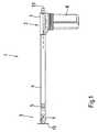
- FIG. 1With reference to Fig. 1 to Fig. 6 Now, an instrument generally designated by reference numeral 1 will be described. Positional and directional information given herein, such as “top” and “bottom”, for purposes of simplicity of description, refers only to the orientation of the instrument 1 shown in the figures. It will be understood that the instrument 1 may be otherwise oriented, so that this information should in no way be construed as limiting.
- the instrument 1explained in connection with the figures serves, in particular, to modify and / or fix an organ in its position, for example to carry out laparoscopic examinations or treatments.
- the instrument 1comprises a proximal instrument part 2 and a distal instrument part 3, which are connected via a Fig. 1 shortened illustrated tubular shaft 4 are interconnected. Through the tube axis of the shaft 4, a longitudinal or longitudinal axis 33 of the instrument 1 is defined.
- the proximal instrument part 2is connected to the proximal end of the shaft 4 with a fixed to the handle 8 for holding the instrument 1 attachment part 7.
- the attachment part 7is fastened to the handle 8 by a conventional, for example, detachable connection, such as a screw or catch connection.
- the attachment part 7can be provided, for example, with a pipe socket (not shown) onto which the handle 8 is pushed.
- the shaft 4is attached in a conventional manner on the attachment part 7, for example, releasably.
- the handle 8comprises a rigidly connected to the attachment part 7 first handle part 49 and a second handle part 50 which can be pivoted on the pivot joint 51 relative to the first handle part 49.
- the distal instrument part 3has a joint head 6 mounted via a connection part 5 at the distal end of the shaft 4, wherein the joint head 6 on the connection part 5 via a conventional releasable connection, such as a screw or locking connection, is attached.
- the connecting part 5is attached to the shaft 4 in a conventional manner releasably or not releasably attached.
- the condyle 6is provided with a base portion 9 that widens radially towards the distal end of the instrument 1, to which a joint portion 10 adjoins distally with two mutually parallel joint forks 11.
- the two joint forks 11extend along the longitudinal axis 33 and form between them an approximately parallelepiped-shaped recess 12 with planar inner surfaces 47 facing one another. They serve for the articulation of a pivoting part 13 on the joint head 6.
- the pivoting part 13is provided with two pivot arms 15, which are encompassed by the two joint forks 11.
- the two pivot arms 15For articulated connection with the joint forks 11, the two pivot arms 15 not shown through holes, which are penetrated by a first hinge pin 17 which is received in each other opposite first bearing bores 16 of the joint forks 11.
- the first hinge pin 17is rotatably mounted in the first bearing bores 16, while the pivot arms 15 are rotatably connected to the first hinge pin 17.
- the first hinge pin 17is rotatably mounted in the first bearing bores 16, while the pivot arms 15 are rotatably connected to the first hinge pin 17.
- pivoting part 13is pivotally mounted on the joint head 6 via a pivoting joint designated overall by the reference numeral 19, hereinafter referred to as "pivoting part joint".
- pivoting part jointBy position and direction of the first hinge pin 17, a first pivot axis 29 is defined, which is perpendicular to the longitudinal axis 33.
- the two pivot arms 15 of the pivoting part 13are connected by a perpendicular to the longitudinal axis 33 arranged support plate 18 with each other.
- the support plate 18, which is located outside of the recess 12 formed by the two joint forks 11,is used for releasably mounting a device according to the specific requirements for the manipulation of the device required (not shown), the spatial position is changed by pivoting the pivot member 13. It would also be conceivable to connect such a device without carrier plate 18 directly to the two pivot arms 15.
- the pivoting part 13is coupled to a translationally movable push / pull rod 20 (referred to in the introduction to the description as an "actuating element").
- the push / pull rod 20is received in a cavity of the tubular shaft 4 and extends proximally through the attachment part 7 to the handle 8 and distally into the condyle 6 inside. It can be moved back and forth by a manually operable mechanism for generating a translational movement, so that it acts as a pull or push rod depending on the respective direction of movement.
- the push / pull rod 20 for this purpose with a mounting portion 52 of the second handle portion 50is fixedly connected (not shown), so that it can be translationally moved by operating the handle 8.
- a sleeve 30made of a low-friction material, such as Teflon.
- Teflona low-friction material
- the pivoting part 13can be pivoted into different angular positions relative to the shaft 4 or longitudinal axis 33 by the push / pull rod 20 that can be moved bidirectionally along the longitudinal axis 33.
- an active couplingis provided, which extends in the longitudinal axis 33 extending, arcuate coupling parts 21 which are connected to both the push / pull rod 20 and the two pivot arms 15 of the pivot member 13 each articulated.
- the proximal ends of the coupling parts 21are articulated to a distal end portion of the push / pull rod 20, namely a rod end 22 articulated to the remaining rod portion 31.
- the rod head 22is provided with a first through hole 23 which is in alignment with second through holes 24 of the two Coupling parts 21 is arranged.
- the first and second through holes 23, 24are penetrated by a second hinge pin 25, which is mounted with its two ends to the joint forks 11.
- the two joint forks 11are provided with apertures formed as scenes 32, in which the ends of the second hinge pin 25 are added.
- either the two coupling parts 21 or the rod head 22are rotatably connected to the second hinge pin 25, while the second hinge pin 25 is rotatably and slidably mounted in the scenes 32.
- the coupling parts 21 and the rod head 22are rotatably connected to the second hinge pin 25, while the second hinge pin 25 rotatably but slidably mounted in the scenes 32.
- proximal coupling part jointpivotally mounted on the rod head 22.
- proximal coupling part jointpivotally mounted on the rod head 22.
- a second pivot axis 37is defined, which is perpendicular to the longitudinal axis 33 and parallel to the first pivot axis 29 of the pivot member 13.
- the two coupling parts 21are each pivotally connected to a pivot arm 15, wherein the two pivot arms 15 engage around the coupling parts 21 fork-shaped.
- the coupling parts 21engage around the two pivot arms 15 or a coupling member 21 with respect to the longitudinal axis 33 outside, the other is mounted within its associated or driven pivot arm 15.
- the coupling parts 21are each provided with second bearing bores 26, in which an integrally formed on the adjacent pivot arm 15 pivot pin 27 is rotatably received.
- distal coupling part jointa third pivot axis 40 is defined, which is perpendicular to the longitudinal axis 33 and parallel to the second pivot axis 37.
- the two coupling parts 21engage outside of the first pivot axis 29 on the two pivot arms 15, so that between the point of application of the distal coupling part joint 39 and the first pivot axis 29, a lever is formed, via which a torque for pivoting the pivot member 13 can be transmitted.
- a spacer 28is provided in the region of the distal coupling part joint 39, by means of which the two coupling parts 21 are stiffened against one another.
- the scenes 32serve as link guide for the second hinge pin 25 of the proximal coupling part joint 36, wherein the two ends of the second hinge pin 25 engage as a crank pin 48 in the scenes 32.
- the scenes 32are formed as openings of the joint forks 11.
- the two scenes 32have in an plane which is spanned by the longitudinal axis 33 and a perpendicular to each of the pivot axes 29, 37, 40, an angular shape. They are composed from proximal to distal from a (linear) longitudinal section 34 extending along the longitudinal axis 33 and a (linear) oblique section 35 extending obliquely to the longitudinal axis 33 with approximately the same length.
- the oblique portion 35 of the scenes 32 relative to the longitudinal axis 33is employed so that when moving the push / pull rod 20 through the distal coupling part joint 39, a torque is exerted on the pivot member 13.
- the inclined portion 35extends for this purpose from proximal to distal in the half-space in which the distal coupling part joint 39 is located.
- the inclined portion 35is opposite the longitudinal axis 33 is angled upward, wherein an angle between the inclined portion 35 and the longitudinal axis 33, for example, about 30 °.
- a different angledepending on the type and design of the joint coupling between the pivot member 13 and the push / pull rod 20 may be provided.
- the rod end 22is articulated to the remainder of the rod portion 31 by a joint generally designated by the reference numeral 41, hereinafter referred to as a "rod head hinge".
- the distal end of the rod portion 31is provided with third through-holes 42, which are penetrated by a third hinge pin 43.
- a fourth pivot axis 44is defined, which is directed perpendicular to the longitudinal axis 33, so that the joint head 6 can follow the course of the inclined portion 35.
- proximal coupling part joint 36is thus guided during translational displacement of the push / pull rod 20 through the scenes 32 directly to pivot the pivot member 13, wherein a 30 formed by the oblique section distal end stop 45 and formed by a longitudinal section 34 proximal end stop 46 respectively endpoints for specify the bidirectional translational movement of the push / pull rod 20 and its distal rod end 22.
- FIG. 12illustrates a situation in which the proximal linkage hinge 36 is approximately centered with respect to the bidirectional travel of the push / pull rod 20.
- the center position of the push / pull rod 20is assigned here, for example, an angular position of the pivot member 13 parallel to the longitudinal axis 33.
- the pivoting part 13thus has no deflection with respect to the shaft 4 (angular position 0 °).
- the pivoting part 13 in the center position of the push / pull rod 20 with respect to the shaft 4has a different angular position from 0 °.
- the pivot member 13is pivoted by the two coupling parts 21 in the opposite direction of rotation, ie clockwise in the figures, until the slide pins 48 of the second Articulated pin 25 comes to rest against the proximal end stop 46 of the scenes 32.
- Fig. 6a situation is shown in which the link pins 48 abut the proximal end stop 46, corresponding to a maximum movement stroke of the push / pull rod 20 to the proximal.
- the pivoting part 13 in this positionon a (here, for example, designated positive degrees) deflection of about -120 °.
- the pivoting part 13, starting from a center position in which the two pivot arms 15 extend parallel to the shaft 4,are pivoted by reciprocating the push / pull rod 20 both in one direction of rotation and in the other direction of rotation.
- the pivoting part 13can be pivoted in an advantageous manner over a relatively wide pivoting range, without these with the two joint forks 11 interconnecting, first hinge pin 17 of the pivoting part joint 19 collide.
- 21 differently shaped coupling partsinstead of arcuate coupling parts.
- straight coupling partscould be used, in which case, if necessary, the first hinge pin 17 of the pivoting part joint 19 would have to be replaced by respective pivot pins between the joint forks 11 and the pivoting arms 15.
- a bendable push / pull rod 20could be provided whose distal end portion is capable of following the path of movement imposed by the links 32.
- the inventive instrument 1the conventional generic instruments are further developed in an advantageous manner, wherein the pivot member 13 is pivotable about a technically easy to implement coupling by means of a translationally movable push / pull rod 20 in both pivoting directions.
Landscapes
- Health & Medical Sciences (AREA)
- Surgery (AREA)
- Life Sciences & Earth Sciences (AREA)
- Biomedical Technology (AREA)
- Medical Informatics (AREA)
- Reproductive Health (AREA)
- Pregnancy & Childbirth (AREA)
- Engineering & Computer Science (AREA)
- Gynecology & Obstetrics (AREA)
- Heart & Thoracic Surgery (AREA)
- Nuclear Medicine, Radiotherapy & Molecular Imaging (AREA)
- Molecular Biology (AREA)
- Animal Behavior & Ethology (AREA)
- General Health & Medical Sciences (AREA)
- Public Health (AREA)
- Veterinary Medicine (AREA)
- Surgical Instruments (AREA)
Description
Translated fromGermanDie Erfindung liegt auf dem Gebiet der Medizintechnik und betrifft nach ihrer Gattung ein medizinisches Instrument gemäß dem Oberbegriff von Anspruch 1.The invention is in the field of medical technology and relates to its genus a medical instrument according to the preamble of
Gattungsgemäße medizinische Instrumente werden im Handel in großer Zahl vertrieben und sind in der einschlägigen Patentliteratur bereits vielfach beschrieben worden. Lediglich beispielhaft sei in diesem Zusammenhang auf die deutsche Gebrauchsmusterschrift
Demgegenüber besteht die Aufgabe der vorliegenden Erfindung darin, ein gattungsgemäßes medizinisches Instrument in vorteilhafter Weise weiterzubilden.In contrast, the object of the present invention is to further develop a generic medical instrument in an advantageous manner.
Diese und weitere Aufgaben werden nach dem Vorschlag der Erfindung durch ein medizinisches Instrument mit den Merkmalen des unabhängigen Anspruchs gelöst. Vorteilhafte Ausgestaltungen der Erfindung sind durch die Merkmale der Unteransprüche angegeben.These and other objects are achieved according to the proposal of the invention by a medical instrument having the features of the independent claim. Advantageous embodiments of the invention are indicated by the features of the subclaims.
Gemäß vorliegender Erfindung umfasst ein medizinisches Instrument einen proximalen Instrumententeil und einen distalen Instrumententeil, die über einen langgestreckten, beispielsweise rohrförmigen Schaft miteinander verbunden sind. Das distale Instrumententeil weist ein in Bezug auf die Längsrichtung bzw. Längsachse des Schafts um eine Schwenkachse schwenkbar gelagertes Schwenkelement auf, das durch ein translatorisch bewegbares Betätigungselement, beispielsweise eine Druck-/Zugstange, verschwenkbar ist.According to the present invention, a medical instrument comprises a proximal instrument part and a distal instrument part, which are connected to one another via an elongated, for example, tubular shaft. The distal instrument part has a pivotable about a pivot axis with respect to the longitudinal or longitudinal axis of the shaft pivotally mounted element, which is pivotable by a translationally movable actuator, such as a push / pull rod.
Das medizinische Instrument zeichnet sich in wesentlicher Weise dadurch aus, dass das Schwenkelement durch wenigstens ein Koppelelement mit dem Betätigungselement gekoppelt ist, wobei das wenigstens eine Koppelelement mit dem Schwenkelement über eine erste Gelenkverbindung und mit dem Betätigungselement über eine zweite Gelenkverbindung jeweils gelenkig verbunden ist. Die erste Gelenkverbindung des Koppelelements verbindet das Koppelelement außerhalb der Schwenkachse des Schwenkelements mit diesem, so dass über das Koppelelement ein Drehmoment auf das Schwenkelement übertragen und das Schwenkelement durch das Koppelelement verschwenkt werden kann. Die erste Gelenkverbindung folgt somit der Schwenkbewegung des Schwenkteils. Die zweite Gelenkverbindung des Koppelements ist durch wenigstens eine vom distalen Instrumententeil geformte nicht-lineare Führung (mittelbar oder unmittelbar) geführt, derart, dass das Schwenkelement sowohl in der einen Schwenkrichtung als auch in der anderen Schwenkrichtung verschwenkbar ist. Zudem ist das Betätigungselement zur Führung durch die nicht-lineare Führung geeignet ausgebildet, so dass es der durch die nicht-lineare Führung vorgegebenen Bewegungsbahn folgen kann. Das Betätigungselement kann zu diesem Zweck beispielsweise einen distalen Endabschnitt aufweisen, der an dem übrigen Abschnitt des Betätigungselements schwenkbar angelenkt ist. Alternativ hierzu ist es beispielsweise auch möglich, dass das Betätigungselement biegbar ausgebildet ist.The medical instrument is characterized in essential way by the fact that the pivoting element is coupled by at least one coupling element with the actuating element, wherein the at least one coupling element with the pivoting element via a first articulated connection and with the actuating element via a second articulated connection is in each case articulated. The first articulated connection of the coupling element connects the coupling element outside the pivot axis of the pivoting element with the latter, so that a torque can be transmitted to the pivoting element via the coupling element and the pivoting element can be pivoted through the coupling element. The first articulated connection thus follows the pivoting movement of the pivoting part. The second articulated connection of the coupling element is guided (indirectly or directly) by at least one non-linear guide formed by the distal instrument part, such that the pivoting element can be pivoted both in one pivoting direction and in the other pivoting direction. In addition, the actuating element is designed to be guided by the non-linear guide so that it can follow the path of movement predetermined by the non-linear guide. For this purpose, the actuating element may, for example, have a distal end section, which is pivotably connected to the remaining section of the actuating element. Alternatively, for example, it is also possible that the actuating element is designed to be bendable.
Das erfindungsgemäße medizinische Instrument ermöglicht somit in vorteilhafter Weise ein Verschwenken des Schwenkelements sowohl in der einen Schwenkrichtung als auch in der anderen Schwenkrichtung. Dies wird in technisch einfacher Weise durch das wenigstens eine Koppelelement zur Übertragung eines Drehmoments auf das Schwenkelement erreicht, welches sowohl am Schwenkelement als auch am Betätigungselement angelenkt ist, wobei die gelenkige Verbindung zwischen Koppelelement und Betätigungselement durch eine nicht-lineare Führung in geeigneter Weise mittelbar oder unmittelbar geführt ist.The medical instrument according to the invention thus advantageously makes it possible to pivot the pivoting element both in one pivoting direction and in the other pivoting direction. This is achieved in a technically simple manner by the at least one coupling element for transmitting torque to the pivot member, which is articulated on both the pivot member and the actuating element, the articulated connection between the coupling element and actuator by a non-linear guide in a suitable manner or indirectly is guided directly.
Bei einer vorteilhaften Ausgestaltung des medizinischen Instruments ist die nicht-lineare Führung winkelig ausgebildet und umfasst einen entlang der durch den Schaft definierten Längsachse sich erstreckenden ersten Abschnitt, im Weiteren als "Längsabschnitt" bezeichnet, und einen schräg zur Längsachse sich erstreckenden, zweiten Abschnitt, im Weiteren als "Schrägabschnitt" bezeichnet. Der Schrägabschnitt ist hierbei so zur Längsachse angestellt, dass über die erste Gelenkverbindung zwischen Koppelelement und Schwenkelement ein Drehmoment auf das Schwenkelement übertragen werden kann.In an advantageous embodiment of the medical instrument, the non-linear guide is angled and comprises a first section extending along the longitudinal axis defined by the shaft, hereinafter referred to as "longitudinal section", and a second section extending obliquely to the longitudinal axis Further referred to as "helical section". The inclined portion is in this case employed to the longitudinal axis, that on the first articulated connection between the coupling element and the pivot element, a torque can be transmitted to the pivot member.
Wie oben bereits ausgeführt, kann in dem erfindungsgemäßen medizinischen Instrument die zweite Gelenkverbindung des Koppelelements von der nicht-linearen Führung unmittelbar (direkt) geführt sein. In diesem Fall kann es besonders vorteilhaft sein, wenn die nicht-lineare Führung in Form einer Kulissenführung ausgebildet ist, wobei die zweite Gelenkverbindung des Koppelelements zu diesem Zweck wenigstens ein als Kulissenzapfen in die Kulissenführung greifendes Gelenkglied aufweisen kann. Durch diese Maßnahme kann eine unmittelbare Führung der zweiten Gelenkverbindung in besonders einfacher Weise realisiert werden.As already stated above, in the medical instrument according to the invention, the second articulated connection of the coupling element can be guided directly (directly) by the non-linear guide. In this case, it may be particularly advantageous if the non-linear guide is designed in the form of a slotted guide, wherein the second articulated connection of the coupling element for this purpose may have at least one link member engaging in the slotted guide link. By this measure, a direct guidance of the second hinge connection can be realized in a particularly simple manner.
Alternativ hierzu ist es auch möglich, dass die zweite Gelenkverbindung des Koppelelements von der nicht-linearen Führung lediglich mittelbar (indirekt) geführt wird. Insbesondere kann in diesem Fall beispielsweise das Betätigungselement von der nicht-linearen Führung geführt sein, um eine mittelbare Führung der zweiten Gelenkverbindung durch die nicht-lineare Führung zu erzielen.Alternatively, it is also possible that the second hinge connection of the coupling element is guided by the non-linear guide only indirectly (indirectly). In particular, in this case, for example, the actuator may be guided by the non-linear guide to achieve an indirect guidance of the second hinge connection by the non-linear guide.
Bei einer weiteren vorteilhaften Ausgestaltung des medizinischen Instruments ist das wenigstens eine Koppelteil bogenförmig ausgebildet. Durch diese Maßnahme kann erreicht werden, dass das Schwenkelement über einen relativ großen Schwenkbereich verschwenkt wird, wobei das bogenförmige Koppelteil über eine Schwenkwelle des Schwenkelements geführt werden kann, ohne dass die Gefahr einer Kollision zwischen Koppelelement und Schwenkwelle besteht.In a further advantageous embodiment of the medical instrument, the at least one coupling part is arcuate. By this measure it can be achieved that the pivoting element is pivoted over a relatively large pivoting range, wherein the arcuate coupling part can be guided over a pivot shaft of the pivoting element, without the risk of a collision between coupling element and pivot shaft.
Bei einer weiteren vorteilhaften Ausgestaltung des medizinischen Instruments ist das Schwenkelement, ausgehend von einer Mittenlage, um wenigstens 90° in der einen Schwenkrichtung und wenigstens 90° in der anderen Schwenkrichtung verschwenkbar, wobei durch diese Maßnahme ein für die praktische Anwendung besonders großer Schwenkbereich realisiert ist.In a further advantageous embodiment of the medical instrument, the pivoting element, starting from a center position, can be pivoted by at least 90 ° in one pivoting direction and at least 90 ° in the other pivoting direction, this measure realizing a particularly large pivotal range for practical use.
Die Erfindung wird nun anhand eines Ausführungsbeispiels näher erläutert, wobei Bezug auf die beigefügten Zeichnungen genommen wird. Es zeigen:
- Fig. 1
- in einer perspektivischen Seitenansicht ein Ausführungsbeispiel des erfindungsgemäßen Instruments;
- Fig. 2
- in einer perspektivischen Ansicht von schräg oben den distalen Instrumententeil des Instruments von
Fig. 1 ; - Fig. 3
- in einer teiltransparenten Seitenansicht den distalen Instrumententeil des Instruments von
Fig. 1 ; - Fig. 4
- in einer teiltransparenten Aufsicht den distalen Instrumententeil des Instruments von
Fig. 1 ; - Fig. 5
- in einer teiltransparenten Seitenansicht den distalen Instrumententeil des Instruments von
Fig. 1 mit einem in der einen Drehrichtung verschwenkten Schwenkteil; - Fig. 6
- in einer teiltransparenten Seitenansicht den distalen Endabschnitt des Instruments von
Fig. 1 mit einem in der anderen Drehrichtung verschwenkten Schwenkteil.
- Fig. 1
- in a perspective side view of an embodiment of the instrument according to the invention;
- Fig. 2
- in a perspective view obliquely from above the distal instrument part of the instrument of
Fig. 1 ; - Fig. 3
- in a partially transparent side view of the distal instrument part of the instrument of
Fig. 1 ; - Fig. 4
- in a semi-transparent top view, the distal instrument part of the instrument of
Fig. 1 ; - Fig. 5
- in a partially transparent side view of the distal instrument part of the instrument of
Fig. 1 with a swivel part pivoted in the one direction of rotation; - Fig. 6
- in a partially transparent side view of the distal end portion of the instrument of
Fig. 1 with a swivel part pivoted in the other direction of rotation.
Unter Bezugnahme auf
Das in Verbindung mit den Figuren erläuterte Instrument 1 dient insbesondere dazu, ein Organ in seiner Lage zu verändern und/oder zu fixieren, beispielsweise um laparaskopische Untersuchungen oder Behandlungen vorzunehmen.The
Das Instrument 1 umfasst einen proximalen Instrumententeil 2 und einen distalen Instrumententeil 3, die über einen in
Der proximale Instrumententeil 2 ist mit dem proximalen Ende des Schafts 4 mit einem mit dem Handgriff 8 zum Halten des Instruments 1 fest verbundenen Aufsatzteil 7 verbunden. Das Aufsatzteil 7 ist durch eine herkömmliche beispielsweise lösbare Verbindung wie eine Schraub- oder Rastverbindung am Handgriff 8 befestigt. Zu diesem Zweck kann das Aufsatzteil 7 beispielsweise mit einem (nicht dargestellten) Rohrstutzen versehen sein, auf den der Handgriff 8 aufgeschoben ist. In entsprechender Weise ist der Schaft 4 in herkömmlicher Weise am Aufsatzteil 7 beispielsweise lösbar angebracht. Der Handgriff 8 umfasst ein mit dem Aufsatzteil 7 starr verbundenes erstes Griffteil 49 sowie ein zweites Griffteil 50, das an dem Schwenkgelenk 51 relativ zum ersten Griffteil 49 verschwenkt werden kann.The
Der distale Instrumententeil 3 weist einen über ein Anschlussteil 5 am distalen Ende des Schafts 4 montierten Gelenkkopf 6 auf, wobei der Gelenkkopf 6 am Anschlussteil 5 über eine herkömmliche lösbare Verbindung, wie beispielsweise eine Schraub- oder Rastverbindung, befestigt ist. Das Anschlussteil 5 ist am Schaft 4 in herkömmlicher Weise lösbar oder auch nicht lösbar angebracht.The
Der Gelenkkopf 6 ist mit einem zum distalen Ende des Instruments 1 hin sich radial verbreiternden Basisabschnitt 9 versehen, an den sich distal ein Gelenkabschnitt 10 mit zwei zueinander parallelen Gelenkgabeln 11 anschließt. Die beiden Gelenkgabeln 11 erstrecken sich entlang der Längsachse 33 und formen zwischen sich eine in etwa quaderförmige Ausnehmung 12 mit einander zugewandten planen Innenflächen 47. Sie dienen zum Anlenken eines Schwenkteils 13 am Gelenkkopf 6.The
Das Schwenkteil 13 ist mit zwei Schwenkarmen 15 versehen, die von den beiden Gelenkgabeln 11 umgriffen werden. Zur gelenkigen Verbindung mit den Gelenkgabeln 11 weisen die beiden Schwenkarme 15 nicht näher dargestellte Durchgangsbohrungen auf, die von einem ersten Gelenkstift 17 durchsetzt werden, der in einander ge-genüberliegenden ersten Lagerbohrungen 16 der Gelenkgabeln 11 aufgenommen ist. In einer ersten Variante ist der erste Gelenkstift 17 drehbar in den ersten Lagerbohrungen 16 gelagert, während die Schwenkarme 15 mit dem ersten Gelenkstift 17 drehfest verbunden sind. In einer zweiten Variante ist der erste Gelenkstift 17 in den ersten Lagerbohrungen 16 drehfest gelagert, während die Schwenkarme 15 mit dem ersten Gelenkstift 17 drehbar verbunden sind. Alternativ wäre es gleichermaßen möglich, dass anstelle des ersten Gelenkstifts 17 jeweils ein Gelenkzapfen zwischen Schwenkarm 15 und benachbarter Gelenkgabel 11 vorgesehen ist, durch den der Schwenkarm 15 relativ zur Gelenkgabel 11 verschwenkt werden kann.The pivoting
Demnach ist das Schwenkteil 13 über ein insgesamt mit der Bezugszahl 19 bezeichnetes Schwenkgelenk, im Folgenden als "Schwenkteilgelenk" bezeichnet, am Gelenkkopf 6 schwenkbar gelagert. Durch Lage und Richtung des ersten Gelenkstifts 17 ist eine erste Schwenkachse 29 definiert, die senkrecht zur Längsachse 33 ist.Accordingly, the pivoting
Die beiden Schwenkarme 15 des Schwenkteils 13 sind durch eine senkrecht zur Längsachse 33 angeordnete Trägerplatte 18 miteinander verbunden. Die Trägerplatte 18, welche sich außerhalb der durch die beiden Gelenkgabeln 11 gebildeten Ausnehmung 12 befindet, dient zur lösbaren Montage einer entsprechend den spezifischen Erfordernissen für die Manipulation des Organs benötigten Einrichtung (nicht dargestellt), deren räumliche Lage durch Verschwenken des Schwenkteils 13 veränderbar ist. Denkbar wäre auch, eine solche Einrichtung ohne Trägerplatte 18 direkt mit den beiden Schwenkarmen 15 zu verbinden.The two
Das Schwenkteil 13 ist mit einer translatorisch bewegbaren Druck-/Zugstange 20 (in der Beschreibungseinleitung als "Betätigungselement" bezeichnet) gekoppelt. Die Druck-/Zugstange 20 ist in einem Hohlraum des rohrförmigen Schafts 4 aufgenommen und erstreckt sich proximal durch das Aufsatzteil 7 hindurch bis zum Handgriff 8 und distal bis in den Gelenkkopf 6 hinein. Sie kann durch einen manuell betätigbaren Mechanismus zum Erzeugen einer translatorischen Bewegung hin und her bewegt werden, so dass sie in Abhängigkeit der jeweiligen Bewegungsrichtung als Zug- oder Druckstange wirkt. In dem in den
Das Schwenkteil 13 kann durch die entlang der Längsachse 33 bidirektional bewegbare Druck-/Zugstange 20 in verschiedene Winkelpositionen relativ zum Schaft 4 bzw. Längsachse 33 verschwenkt werden. Zu diesem Zweck ist eine Wirkkopplung vorgesehen, die in Längsachse 33 sich erstreckende, bogenförmige Koppelteile 21 umfasst, die sowohl mit der Druck-/Zugstange 20 als auch mit den beiden Schwenkarmen 15 des Schwenkteils 13 jeweils gelenkig verbunden sind. Insbesondere sind die proximalen Enden der Koppelteile 21 an einen distalen Endabschnitt der Druck-/Zugstange 20, nämlich einen mit dem übrigen Stangenabschnitt 31 gelenkig verbundenen Stangenkopf 22, angelenkt. Für eine gelenkige Verbindung zwischen dem Stangenkopf 22 und den beiden den Stangenkopf 22 gabelförmig umgreifenden Koppelteilen 21, ist der Stangenkopf 22 mit einer ersten Durchgangsbohrung 23 versehen, die fluchtend zu zweiten Durchgangsbohrungen 24 der beiden Koppelteile 21 angeordnet ist. Die ersten und zweiten Durchgangsbohrungen 23, 24 werden von einem zweiten Gelenkstift 25 durchsetzt, der mit seinen beiden Enden an den Gelenkgabeln 11 gelagert ist. Zu Lagerung des zweiten Gelenkstifts 25 sind die beiden Gelenkgabeln 11 mit als Durchbrechungen ausgebildeten Kulissen 32 versehen, in denen die Enden des zweiten Gelenkstifts 25 aufgenommen sind. In einer ersten Variante sind entweder die beiden Koppelteile 21 oder der Stangenkopf 22 drehfest mit dem zweiten Gelenkstift 25 verbunden, während der zweite Gelenkstift 25 drehbar und verschiebbar in den Kulissen 32 gelagert ist. In einer zweiten Variante sind die Koppelteile 21 und der Stangenkopf 22 drehbar mit dem zweiten Gelenkstift 25 verbunden, während der zweite Gelenkstift 25 drehfest, aber verschiebbar in den Kulissen 32 gelagert ist.The pivoting
Demnach sind die beiden Koppelteile 21 über ein insgesamt mit der Bezugszahl 36 bezeichnetes Gelenk, im Weiteren als "proximales Koppelteilgelenk" bezeichnet, am Stangenkopf 22 schwenkbar gelagert. Durch Lage und Ausrichtung des zweiten Gelenkstifts 25 ist eine zweite Schwenkachse 37 definiert, die senkrecht zur Längsachse 33 bzw. parallel zur ersten Schwenkachse 29 des Schwenkteils 13 verläuft.Accordingly, the two
An ihren anderen Enden sind die beiden Koppelteile 21 jeweils mit einem Schwenkarm 15 gelenkig verbunden, wobei die beiden Schwenkarme 15 die Koppelteile 21 gabelförmig umgreifen. Altermativ ist natürlich auch eine Ausführung möglich, bei der die Koppelteile 21 die beiden Schwenkarme 15 umgreifen oder aber ein Koppelteil 21 bezüglich der Längsachse 33 außerhalb, das andere innerhalb seines zugehörigen bzw. angesteuerten Schwenkarms 15 angebracht ist. Zur gelenkigen Verbindung der Koppelteile 21 mit den Schwenkarmen 15 sind die Koppelteile 21 jeweils mit zweiten Lagerbohrungen 26 versehen, in denen ein am benachbarten Schwenkarm 15 angeformter Gelenkzapfen 27 drehbar aufgenommen ist. Alternativ wäre es gleichermaßen möglich, dass die Gelenkzapfen 27 an den Koppelteilen 21 angeformt und in entsprechenden Lagerbohrungen der Schwenkarme 15 drehbar aufgenommen sind.At their other ends, the two
Demnach sind die beiden Koppelteile 21 über ein insgesamt mit der Bezugszahl 39 bezeichnetes Gelenk, im Weiteren als "distales Koppelteilgelenk" bezeichnet, an den Schwenkarmen 15 schwenkbar gelagert. Durch Lage und Ausrichtung der beiden Gelenkzapfen 27 ist eine dritte Schwenkachse 40 definiert, die senkrecht zur Längsachse 33 bzw. parallel zur zweiten Schwenkachse 37 verläuft.Accordingly, the two
Die beiden Koppelteile 21 greifen außerhalb der ersten Schwenkachse 29 an den beiden Schwenkarmen 15 an, so dass zwischen dem Angriffspunkt des distalen Koppelteilgelenks 39 und der ersten Schwenkachse 29 ein Hebel gebildet ist, über den ein Drehmoment zum Verschwenken des Schwenkteils 13 übertragen werden kann. Zwischen den beiden Koppelteilen 21 ist im Bereich des distalen Koppelteilgelenks 39 ein Distanzstück 28 vorgesehen, durch das die beiden Koppelteile 21 gegeneinander versteift werden.The two
Bei einer translatorischen Bewegung der Druck-/Zugstange 20 dienen die Kulissen 32 als Kulissenführung für den zweiten Gelenkstift 25 des proximalen Koppelteilgelenks 36, wobei die beiden Enden des zweiten Gelenkstifts 25 als Kulissenzapfen 48 in die Kulissen 32 greifen. Im vorliegenden Ausführungsbeispiel sind die Kulissen 32 als Durchbrechungen der Gelenkgabeln 11 ausgebildet. Alternativ wäre es gleichermaßen möglich, die Kulissen 32 beispielsweise als nutartige Einformungen der einander zugewandten Innenflächen 47 der Gelenkgabeln 11 auszubilden.In a translatory movement of the push / pull rod 20, the
Die beiden Kulissen 32 haben in einer Ebene, die von der Längsachse 33 und einer Senkrechten zu einer jeden der Schwenkachsen 29, 37, 40 aufgespannt wird, eine winkelige Form. Sie setzen sich von proximal nach distal aus einem entlang der Längsachse 33 sich erstreckenden (linearen) Längsabschnitt 34 und einem schräg zur Längsachse 33 sich erstreckenden (linearen) Schrägabschnitt 35 mit in etwa gleicher Länge zusammen. In den Figuren ist der Schrägabschnitt 35 der Kulissen 32 gegenüber der Längsachse 33 so angestellt, dass beim Verschieben der Druck-/Zugstange 20 durch das distale Koppelteilgelenk 39 ein Drehmoment auf das Schwenkteil 13 ausgeübt wird. Bezogen auf eine Ebene, die durch die Längsachse 33 und die erste Schwenkachse 29 des Schwenkteilgelenks 19 aufgespannt ist, erstreckt sich der Schrägabschnitt 35 zu diesem Zweck von proximal nach distal in jenen Halbraum hinein, in dem sich das distale Koppelteilgelenk 39 befindet. In dem in den Figuren gezeigten Ausführungsbeispiel ist der Schrägabschnitt 35 gegenüber der Längsachse 33 nach oben abgewinkelt, wobei ein Winkel zwischen dem Schrägabschnitt 35 und der Längsachse 33 beispielsweise ca. 30° beträgt. Jedoch kann ein hiervon abweichender Winkel, je nach Art und Auslegung der Gelenkkopplung zwischen dem Schwenkteil 13 und der Druck-/Zugstange 20 vorgesehen sein.The two
Damit der Stangenkopf 22 der durch die beiden Kulissen 32 auferlegten, nicht-geraden Bewegungsbahn folgen kann, ist der Stangenkopf 22 durch ein insgesamt mit der Bezugszahl 41 bezeichnetes Gelenk, im Weiteren als "Stangenkopfgelenk" bezeichnet, am restlichen Stangenabschnitt 31 angelenkt. Zu diesem Zweck ist das distale Ende des Stangenabschnitts 31 mit dritten Durchgangsbohrungen 42 versehen, welche von einem dritten Gelenkstift 43 durchsetzt werden. Durch den dritten Gelenkstift 43 ist eine vierte Schwenkachse 44 definiert, die senkrecht zur Längsachse 33 gerichtet ist, so dass der Gelenkkopf 6 dem Verlauf des Schrägabschnitts 35 folgen kann.In order for the
Das proximale Koppelteilgelenk 36 wird somit beim translatorischen Verschieben der Druck-/Zugstange 20 durch die Kulissen 32 unmittelbar geführt, um das Schwenkteil 13 zu verschwenken, wobei ein vom Schrägabschnitt 35 geformter distaler Endanschlag 45 und ein vom Längsabschnitt 34 geformter proximaler Endanschlag 46 jeweils Endpunkte für die bidirektionale translatorische Bewegung der Druck-/Zugstange 20 bzw. ihren distalen Stangenkopf 22 vorgeben.The proximal coupling part joint 36 is thus guided during translational displacement of the push / pull rod 20 through the
In
Wird die Druck-/Zugstange 20 aus ihrer Mittenlage translatorisch nach distal verschoben, hat dies zur Folge, dass das Schwenkteil 13 durch die beiden Koppelteile 21 in der einen Drehrichtung (in den Figuren entgegen dem Gegenuhrzeigersinn) verschwenkt wird, bis die Kulissenzapfen 48 des zweiten Gelenkstifts 25 des proximalen Koppelteilgelenks 36 zur Anlage gegen den distalen Endanschlag 45 der Kulissen 32 gelangen. In
Wird die Druck-/Zugstange 20 aus ihrer Mittenlage in der entgegen gesetzten Bewegungsrichtung translatorisch nach proximal verschoben, wird das Schwenkteil 13 durch die beiden Koppelteile 21 in der entgegen gesetzten Drehrichtung, d.h. in den Figuren im Uhrzeigersinn, verschwenkt, bis die Kulissenzapfen 48 des zweiten Gelenkstifts 25 zur Anlage gegen den proximalen Endanschlag 46 der Kulissen 32 gelangt. In
Demnach kann das Schwenkteil 13, ausgehend von einer Mittenlage, in der sich die beiden Schwenkarme 15 parallel zum Schaft 4 erstrecken, durch Hin- und Herbewegen der Druck-/Zugstange 20 sowohl in der einen Drehrichtung als auch in der anderen Drehrichtung verschwenkt werden.Accordingly, the pivoting
Durch die bogenförmige Ausgestaltung der Koppelteile 21 kann das Schwenkteil 13 in vorteilhafter Weise über einen relativ weiten Schwenkbereich verschwenkt werden, ohne dass diese mit dem die beiden Gelenkgabeln 11 miteinander verbindenden, ersten Gelenkstift 17 des Schwenkteilgelenks 19 kollidieren. Jedoch wäre es gleichermaßen auch möglich, anstelle bogenförmiger Koppelteile 21 anders geformte Koppelteile vorzusehen. Beispielsweise könnten gerade Koppelteile eingesetzt werden, wobei in diesem Fall gegebenenfalls der erste Gelenkstift 17 des Schwenkteilgelenks 19 durch jeweilige Gelenkzapfen zwischen den Gelenkgabeln 11 und den Schwenkarmen 15 zu ersetzen wäre. Gleichermaßen könnte anstelle des am Stangenabschnitt 31 mittels des Stangenkopfgelenks 41 angelenkten Stangenkopfs 22 eine biegbare Druck-/Zugstange 20 vorgesehen sein, deren distaler Endabschnitt in der Lage ist, der durch die Kulissen 32 auferlegten Bewegungsbahn zu folgen.Due to the arcuate configuration of the
Durch das erfindungsgemäße Instrument 1 werden die herkömmlichen gattungsgemäßen Instrumente in vorteilhafter Weise weitergebildet, wobei das Schwenkteil 13 über eine technisch einfach zu realisierenden Kopplung mittels einer translatorisch bewegbaren Druck-/Zugstange 20 in beiden Schwenkrichtungen verschwenkbar ist.The
- 11
- Instrumentinstrument
- 22
- proximaler Instrumententeilproximal part of the instrument
- 33
- distaler Instrumententeildistal part of the instrument
- 44
- Schaftshaft
- 55
- Anschlussteilconnector
- 66
- Gelenkkopfjoint head
- 77
- Aufsatzteilattachment
- 88th
- Handgriffhandle
- 99
- Basisabschnittbase section
- 1010
- Gelenkabschnitthinge section
- 1111
- Gelenkgabelyoke
- 1212
- Ausnehmungrecess
- 1313
- Schwenkteilpivoting part
- 1414
- Axialbohrungaxial bore
- 1515
- Schwenkarmswivel arm
- 1616
- erste Lagerbohrungfirst bearing bore
- 1717
- erster Gelenkstiftfirst hinge pin
- 1818
- Trägerplattesupport plate
- 1919
- SchwenkteilgelenkPivot member joint
- 2020
- Druck-/ZugstangePressure / pull rod
- 2121
- Koppelteilcoupling part
- 2222
- Stangenkopfrod End
- 2323
- erste Durchgangsbohrungfirst through hole
- 2424
- zweite Durchgangsbohrungsecond through-hole
- 2525
- zweiter Gelenkstiftsecond hinge pin
- 2626
- zweite Lagerbohrungsecond bearing bore
- 2727
- Gelenkzapfenpivot pin
- 2828
- Distanzstückspacer
- 2929
- erste Schwenkachsefirst pivot axis
- 3030
- Hülseshell
- 3131
- Stangenabschnittslug
- 3232
- Kulissescenery
- 3333
- Längsachselongitudinal axis
- 3434
- Längsabschnittlongitudinal section
- 3535
- Schrägabschnittoblique section
- 3636
- proximales Koppelteilgelenkproximal coupling part joint
- 3737
- zweite Schwenkachsesecond pivot axis
- 3939
- distales Koppelteilgelenkdistal coupling part joint
- 4040
- dritte Schwenkachsethird pivot axis
- 4141
- StangenkopfgelenkRod end joint
- 4242
- dritte Durchgangsbohrungthird through hole
- 4343
- dritter Gelenkstiftthird hinge pin
- 4444
- vierte Schwenkachsefourth pivot axis
- 4545
- distaler Endanschlagdistal end stop
- 4646
- proximaler Endanschlagproximal end stop
- 4747
- Innenflächepalm
- 4848
- Kulissenzapfenlink pin
- 4949
- erstes Griffteilfirst handle part
- 5050
- zweites Griffteilsecond handle part
- 5151
- Schwenkgelenkpivot
- 5252
- Befestigungsabschnittattachment section
Claims (11)
- Medical Instrument (1) with a proximal instrument part (2) and a distal instrument part (3) that are connected to each other by an elongate shaft (4), the distal instrument part (3) comprising a pivot element (13) which is mounted pivotably with respect to the shaft (4) and can be pivoted by an actuation element (20) movable in translation,characterised in that- the pivot element (13) is coupled to the actuation clement (20) by at least one coupling element (21), wherein the coupling element (21) is connected in an articulated manner to the pivot element (13) via a first hinge connection (39) and to the actuation element (20) via a second hinge connection (36),- the second hinge connection (36) of the coupling element (21) is guided by at least one non-linear guide (32) formed by the distal instrument part (3), such that the pivot element (13) is pivotable both in one direction of pivoting and in the other direction of pivoting, and- the actuation element (20) is suitably designed to be guided by the non-linear guide (32).
- Medical instrument (1) according to Claim 1,characterized in that the non-linear guide (32) has an angled configuration, with a longitudinal portion (34) extending in the longitudinal axis (33) of the shaft (4), and with an oblique portion (35) extending obliquely with respect to the longitudinal axis (33).
- Medical instrument (1) according to either of Claims 1 and 2,characterized in that the second hinge connection (36) of the coupling element (21) is guided directly by the non-linear guide (32).
- Medical instrument (1) according to Claim 3,characterized in that the non-linear guide (32) is designed as a slotted guide.
- Medical instrument (1) according to Claim 4,characterized in that the second hinge connection (36) of the coupling element (21) comprises at least one hinge member (25) engaging in the slotted guide (32).
- Medical instrument (1) according to either of Claims 1 and 2,characterized in that the second hinge connection (36) of the coupling element (21) is guided indirectly by the non-linear guide (32).
- Medical instrument (1) according to one of Claims 1 to 6,characterized in that the actuation element (20) has a distal end portion (22), which is articulated pivotably on another portion (31) of the actuation element (20).
- Medical instrument (1) according to one of Claims 1 to 6,characterized in that the actuation element (20) is designed to be flexible.
- Medical instrument (1) according to one of Claims 1 to 8,characterized by at least one arc-shaped coupling element (21).
- Medical instrument (1) according to one of Claims 1 to 9,characterized in that the distal instrument part (3) comprises a forked portion (10) for the articulation of the pivot element (13).
- Medical instrument (1) according to one of Claims 1 to 10,characterized in that the pivot element (13), starting from a middle position, is pivotable through at least 90° in one direction of pivoting and at least 90° in the other direction of pivoting.
Applications Claiming Priority (1)
| Application Number | Priority Date | Filing Date | Title |
|---|---|---|---|
| DE102010010947ADE102010010947A1 (en) | 2010-03-10 | 2010-03-10 | Medical instrument |
Publications (2)
| Publication Number | Publication Date |
|---|---|
| EP2364655A1 EP2364655A1 (en) | 2011-09-14 |
| EP2364655B1true EP2364655B1 (en) | 2013-05-08 |
Family
ID=44168815
Family Applications (1)
| Application Number | Title | Priority Date | Filing Date |
|---|---|---|---|
| EP20110157250ActiveEP2364655B1 (en) | 2010-03-10 | 2011-03-08 | Medical instrument |
Country Status (3)
| Country | Link |
|---|---|
| US (1) | US8945097B2 (en) |
| EP (1) | EP2364655B1 (en) |
| DE (1) | DE102010010947A1 (en) |
Families Citing this family (7)
| Publication number | Priority date | Publication date | Assignee | Title |
|---|---|---|---|---|
| JP6302842B2 (en)* | 2012-01-06 | 2018-04-11 | シン, ジワン スティーブンSINGH, Jiwan Steven | Insertion device and insertion system for laparoscopic instruments |
| DE102012007645A1 (en)* | 2012-04-18 | 2013-10-24 | Karl Storz Gmbh & Co. Kg | Medical instrument with bendable shaft |
| WO2013192449A1 (en)* | 2012-06-20 | 2013-12-27 | Peter Scott Borden | Adjustable tissue cutter tool |
| GB201404614D0 (en) | 2014-03-14 | 2014-04-30 | Univ Liverpool | Device for compressing the uterus |
| USD759815S1 (en)* | 2014-03-24 | 2016-06-21 | Karl Storz Gmbh & Co. Kg | Cholangiography catheter guide |
| USD771809S1 (en)* | 2014-07-11 | 2016-11-15 | Karl Storz Gmbh & Co. Kg | Endoscopic instrument for retrograde biopsy |
| USD825056S1 (en)* | 2016-02-03 | 2018-08-07 | Karl Storz Gmbh & Co. Kg | Optical forceps |
Family Cites Families (10)
| Publication number | Priority date | Publication date | Assignee | Title |
|---|---|---|---|---|
| US5391180A (en)* | 1991-08-05 | 1995-02-21 | United States Surgical Corporation | Articulating endoscopic surgical apparatus |
| US5237985A (en)* | 1992-06-22 | 1993-08-24 | Crystal Wind, Inc. | Uterine retractor |
| US5382252A (en)* | 1994-03-24 | 1995-01-17 | Ethicon Endo-Surgery | Transvaginal uterine manipulator |
| US7699835B2 (en)* | 2001-02-15 | 2010-04-20 | Hansen Medical, Inc. | Robotically controlled surgical instruments |
| DE10111766B4 (en)* | 2001-03-12 | 2007-11-22 | Karl Storz Gmbh & Co. Kg | Medical instrument |
| US6994708B2 (en)* | 2001-04-19 | 2006-02-07 | Intuitive Surgical | Robotic tool with monopolar electro-surgical scissors |
| GB2390028A (en)* | 2002-05-10 | 2003-12-31 | Precimed Sa | Pivoting bone reamer for minimally invasive joint surgery |
| JP4460890B2 (en)* | 2003-12-15 | 2010-05-12 | 衛 光石 | Multi-DOF manipulator |
| DE202004019868U1 (en) | 2004-12-16 | 2005-02-24 | Karl Storz Gmbh & Co. Kg | Gynaecological instrument used as uterus manipulator, has locking mechanism for tool actuator operated by sliding handle |
| US8062306B2 (en)* | 2006-12-14 | 2011-11-22 | Ethicon Endo-Surgery, Inc. | Manually articulating devices |
- 2010
- 2010-03-10DEDE102010010947Apatent/DE102010010947A1/ennot_activeWithdrawn
- 2011
- 2011-03-08EPEP20110157250patent/EP2364655B1/enactiveActive
- 2011-03-10USUS13/045,235patent/US8945097B2/enactiveActive
Also Published As
| Publication number | Publication date |
|---|---|
| EP2364655A1 (en) | 2011-09-14 |
| DE102010010947A1 (en) | 2011-09-15 |
| US8945097B2 (en) | 2015-02-03 |
| US20110264079A1 (en) | 2011-10-27 |
Similar Documents
| Publication | Publication Date | Title |
|---|---|---|
| EP2364655B1 (en) | Medical instrument | |
| DE10102089C1 (en) | Surgical instrument | |
| EP1649816B1 (en) | Deflectable endoscopic instrument | |
| EP1464289B1 (en) | Surgical instrument, in which movements of the head and of the effector are decoupled | |
| EP1054636B1 (en) | Handle for a medical instrument | |
| DE69318324T2 (en) | Articulated endoscopic surgical device | |
| EP2298196B1 (en) | Medical instrument | |
| EP2612609B1 (en) | Medical instrument | |
| DE102007021658A1 (en) | Dismountable medical forceps system | |
| DE10324844A1 (en) | Surgical instrument with instrument handle and zero point adjustment | |
| DE10330604A1 (en) | Surgical instrument | |
| EP1486172A1 (en) | Surgical instrument | |
| WO2015139674A1 (en) | Robot system | |
| DE69223382T2 (en) | Endoscopic surgical instruments and jaw structure | |
| EP3351191B1 (en) | Surgical instrument, in particular for neurosurgery | |
| WO2014124846A1 (en) | Instrument, in particular medical endoscopic instrument or technoscope | |
| EP1488749A1 (en) | Medical instrument | |
| DE202016107261U1 (en) | Non-invasive and freely bendable vascular occlusion forceps | |
| EP2371308B1 (en) | Medical instrument | |
| EP1629785B1 (en) | Medical forceps | |
| DE3739254A1 (en) | Medical, in particular surgical, instrument | |
| EP3503820B1 (en) | Surgical jaw-type instrument comprising a counterbalanced lever system | |
| DE10207207A1 (en) | Medical instrument | |
| DE202007000427U1 (en) | Surgical handle and surgical instrument | |
| DE102013003316B4 (en) | Surgical jaw instrument |
Legal Events
| Date | Code | Title | Description |
|---|---|---|---|
| PUAI | Public reference made under article 153(3) epc to a published international application that has entered the european phase | Free format text:ORIGINAL CODE: 0009012 | |
| AK | Designated contracting states | Kind code of ref document:A1 Designated state(s):AL AT BE BG CH CY CZ DE DK EE ES FI FR GB GR HR HU IE IS IT LI LT LU LV MC MK MT NL NO PL PT RO RS SE SI SK SM TR | |
| AX | Request for extension of the european patent | Extension state:BA ME | |
| 17P | Request for examination filed | Effective date:20120207 | |
| RIC1 | Information provided on ipc code assigned before grant | Ipc:A61B 17/42 20060101AFI20120730BHEP Ipc:A61B 17/29 20060101ALN20120730BHEP | |
| GRAP | Despatch of communication of intention to grant a patent | Free format text:ORIGINAL CODE: EPIDOSNIGR1 | |
| RIC1 | Information provided on ipc code assigned before grant | Ipc:A61B 17/29 20060101ALN20120913BHEP Ipc:A61B 17/42 20060101AFI20120913BHEP | |
| GRAS | Grant fee paid | Free format text:ORIGINAL CODE: EPIDOSNIGR3 | |
| GRAA | (expected) grant | Free format text:ORIGINAL CODE: 0009210 | |
| AK | Designated contracting states | Kind code of ref document:B1 Designated state(s):AL AT BE BG CH CY CZ DE DK EE ES FI FR GB GR HR HU IE IS IT LI LT LU LV MC MK MT NL NO PL PT RO RS SE SI SK SM TR | |
| REG | Reference to a national code | Ref country code:GB Ref legal event code:FG4D Free format text:NOT ENGLISH | |
| REG | Reference to a national code | Ref country code:CH Ref legal event code:EP Ref country code:AT Ref legal event code:REF Ref document number:610674 Country of ref document:AT Kind code of ref document:T Effective date:20130515 | |
| REG | Reference to a national code | Ref country code:IE Ref legal event code:FG4D Free format text:LANGUAGE OF EP DOCUMENT: GERMAN | |
| REG | Reference to a national code | Ref country code:DE Ref legal event code:R096 Ref document number:502011000712 Country of ref document:DE Effective date:20130704 | |
| REG | Reference to a national code | Ref country code:LT Ref legal event code:MG4D | |
| REG | Reference to a national code | Ref country code:NL Ref legal event code:VDEP Effective date:20130508 | |
| PG25 | Lapsed in a contracting state [announced via postgrant information from national office to epo] | Ref country code:NO Free format text:LAPSE BECAUSE OF FAILURE TO SUBMIT A TRANSLATION OF THE DESCRIPTION OR TO PAY THE FEE WITHIN THE PRESCRIBED TIME-LIMIT Effective date:20130808 Ref country code:IS Free format text:LAPSE BECAUSE OF FAILURE TO SUBMIT A TRANSLATION OF THE DESCRIPTION OR TO PAY THE FEE WITHIN THE PRESCRIBED TIME-LIMIT Effective date:20130908 Ref country code:FI Free format text:LAPSE BECAUSE OF FAILURE TO SUBMIT A TRANSLATION OF THE DESCRIPTION OR TO PAY THE FEE WITHIN THE PRESCRIBED TIME-LIMIT Effective date:20130508 Ref country code:PT Free format text:LAPSE BECAUSE OF FAILURE TO SUBMIT A TRANSLATION OF THE DESCRIPTION OR TO PAY THE FEE WITHIN THE PRESCRIBED TIME-LIMIT Effective date:20130909 Ref country code:GR Free format text:LAPSE BECAUSE OF FAILURE TO SUBMIT A TRANSLATION OF THE DESCRIPTION OR TO PAY THE FEE WITHIN THE PRESCRIBED TIME-LIMIT Effective date:20130809 Ref country code:SI Free format text:LAPSE BECAUSE OF FAILURE TO SUBMIT A TRANSLATION OF THE DESCRIPTION OR TO PAY THE FEE WITHIN THE PRESCRIBED TIME-LIMIT Effective date:20130508 Ref country code:SE Free format text:LAPSE BECAUSE OF FAILURE TO SUBMIT A TRANSLATION OF THE DESCRIPTION OR TO PAY THE FEE WITHIN THE PRESCRIBED TIME-LIMIT Effective date:20130508 Ref country code:LT Free format text:LAPSE BECAUSE OF FAILURE TO SUBMIT A TRANSLATION OF THE DESCRIPTION OR TO PAY THE FEE WITHIN THE PRESCRIBED TIME-LIMIT Effective date:20130508 Ref country code:ES Free format text:LAPSE BECAUSE OF FAILURE TO SUBMIT A TRANSLATION OF THE DESCRIPTION OR TO PAY THE FEE WITHIN THE PRESCRIBED TIME-LIMIT Effective date:20130819 | |
| PG25 | Lapsed in a contracting state [announced via postgrant information from national office to epo] | Ref country code:CY Free format text:LAPSE BECAUSE OF FAILURE TO SUBMIT A TRANSLATION OF THE DESCRIPTION OR TO PAY THE FEE WITHIN THE PRESCRIBED TIME-LIMIT Effective date:20130508 Ref country code:HR Free format text:LAPSE BECAUSE OF FAILURE TO SUBMIT A TRANSLATION OF THE DESCRIPTION OR TO PAY THE FEE WITHIN THE PRESCRIBED TIME-LIMIT Effective date:20130508 Ref country code:BG Free format text:LAPSE BECAUSE OF FAILURE TO SUBMIT A TRANSLATION OF THE DESCRIPTION OR TO PAY THE FEE WITHIN THE PRESCRIBED TIME-LIMIT Effective date:20130808 Ref country code:PL Free format text:LAPSE BECAUSE OF FAILURE TO SUBMIT A TRANSLATION OF THE DESCRIPTION OR TO PAY THE FEE WITHIN THE PRESCRIBED TIME-LIMIT Effective date:20130508 Ref country code:RS Free format text:LAPSE BECAUSE OF FAILURE TO SUBMIT A TRANSLATION OF THE DESCRIPTION OR TO PAY THE FEE WITHIN THE PRESCRIBED TIME-LIMIT Effective date:20130508 | |
| PG25 | Lapsed in a contracting state [announced via postgrant information from national office to epo] | Ref country code:LV Free format text:LAPSE BECAUSE OF FAILURE TO SUBMIT A TRANSLATION OF THE DESCRIPTION OR TO PAY THE FEE WITHIN THE PRESCRIBED TIME-LIMIT Effective date:20130508 | |
| PG25 | Lapsed in a contracting state [announced via postgrant information from national office to epo] | Ref country code:DK Free format text:LAPSE BECAUSE OF FAILURE TO SUBMIT A TRANSLATION OF THE DESCRIPTION OR TO PAY THE FEE WITHIN THE PRESCRIBED TIME-LIMIT Effective date:20130508 Ref country code:EE Free format text:LAPSE BECAUSE OF FAILURE TO SUBMIT A TRANSLATION OF THE DESCRIPTION OR TO PAY THE FEE WITHIN THE PRESCRIBED TIME-LIMIT Effective date:20130508 Ref country code:CZ Free format text:LAPSE BECAUSE OF FAILURE TO SUBMIT A TRANSLATION OF THE DESCRIPTION OR TO PAY THE FEE WITHIN THE PRESCRIBED TIME-LIMIT Effective date:20130508 Ref country code:SK Free format text:LAPSE BECAUSE OF FAILURE TO SUBMIT A TRANSLATION OF THE DESCRIPTION OR TO PAY THE FEE WITHIN THE PRESCRIBED TIME-LIMIT Effective date:20130508 | |
| PG25 | Lapsed in a contracting state [announced via postgrant information from national office to epo] | Ref country code:NL Free format text:LAPSE BECAUSE OF FAILURE TO SUBMIT A TRANSLATION OF THE DESCRIPTION OR TO PAY THE FEE WITHIN THE PRESCRIBED TIME-LIMIT Effective date:20130508 Ref country code:RO Free format text:LAPSE BECAUSE OF FAILURE TO SUBMIT A TRANSLATION OF THE DESCRIPTION OR TO PAY THE FEE WITHIN THE PRESCRIBED TIME-LIMIT Effective date:20130508 | |
| PLBE | No opposition filed within time limit | Free format text:ORIGINAL CODE: 0009261 | |
| STAA | Information on the status of an ep patent application or granted ep patent | Free format text:STATUS: NO OPPOSITION FILED WITHIN TIME LIMIT | |
| 26N | No opposition filed | Effective date:20140211 | |
| REG | Reference to a national code | Ref country code:DE Ref legal event code:R097 Ref document number:502011000712 Country of ref document:DE Effective date:20140211 | |
| PG25 | Lapsed in a contracting state [announced via postgrant information from national office to epo] | Ref country code:LU Free format text:LAPSE BECAUSE OF FAILURE TO SUBMIT A TRANSLATION OF THE DESCRIPTION OR TO PAY THE FEE WITHIN THE PRESCRIBED TIME-LIMIT Effective date:20140308 | |
| REG | Reference to a national code | Ref country code:CH Ref legal event code:PL | |
| REG | Reference to a national code | Ref country code:IE Ref legal event code:MM4A | |
| PG25 | Lapsed in a contracting state [announced via postgrant information from national office to epo] | Ref country code:CH Free format text:LAPSE BECAUSE OF NON-PAYMENT OF DUE FEES Effective date:20140331 Ref country code:IE Free format text:LAPSE BECAUSE OF NON-PAYMENT OF DUE FEES Effective date:20140308 Ref country code:LI Free format text:LAPSE BECAUSE OF NON-PAYMENT OF DUE FEES Effective date:20140331 | |
| REG | Reference to a national code | Ref country code:FR Ref legal event code:PLFP Year of fee payment:6 | |
| PG25 | Lapsed in a contracting state [announced via postgrant information from national office to epo] | Ref country code:MT Free format text:LAPSE BECAUSE OF FAILURE TO SUBMIT A TRANSLATION OF THE DESCRIPTION OR TO PAY THE FEE WITHIN THE PRESCRIBED TIME-LIMIT Effective date:20130508 | |
| PG25 | Lapsed in a contracting state [announced via postgrant information from national office to epo] | Ref country code:SM Free format text:LAPSE BECAUSE OF FAILURE TO SUBMIT A TRANSLATION OF THE DESCRIPTION OR TO PAY THE FEE WITHIN THE PRESCRIBED TIME-LIMIT Effective date:20130508 | |
| PG25 | Lapsed in a contracting state [announced via postgrant information from national office to epo] | Ref country code:MC Free format text:LAPSE BECAUSE OF FAILURE TO SUBMIT A TRANSLATION OF THE DESCRIPTION OR TO PAY THE FEE WITHIN THE PRESCRIBED TIME-LIMIT Effective date:20130508 | |
| PG25 | Lapsed in a contracting state [announced via postgrant information from national office to epo] | Ref country code:TR Free format text:LAPSE BECAUSE OF FAILURE TO SUBMIT A TRANSLATION OF THE DESCRIPTION OR TO PAY THE FEE WITHIN THE PRESCRIBED TIME-LIMIT Effective date:20130508 Ref country code:HU Free format text:LAPSE BECAUSE OF FAILURE TO SUBMIT A TRANSLATION OF THE DESCRIPTION OR TO PAY THE FEE WITHIN THE PRESCRIBED TIME-LIMIT; INVALID AB INITIO Effective date:20110308 | |
| REG | Reference to a national code | Ref country code:FR Ref legal event code:PLFP Year of fee payment:7 | |
| REG | Reference to a national code | Ref country code:AT Ref legal event code:MM01 Ref document number:610674 Country of ref document:AT Kind code of ref document:T Effective date:20160308 | |
| PG25 | Lapsed in a contracting state [announced via postgrant information from national office to epo] | Ref country code:BE Free format text:LAPSE BECAUSE OF NON-PAYMENT OF DUE FEES Effective date:20140331 | |
| PG25 | Lapsed in a contracting state [announced via postgrant information from national office to epo] | Ref country code:AT Free format text:LAPSE BECAUSE OF NON-PAYMENT OF DUE FEES Effective date:20160308 | |
| REG | Reference to a national code | Ref country code:DE Ref legal event code:R081 Ref document number:502011000712 Country of ref document:DE Owner name:KARL STORZ SE & CO. KG INTELLECTUAL PROPERTY, DE Free format text:FORMER OWNER: KARL STORZ GMBH & CO. KG, 78532 TUTTLINGEN, DE Ref country code:DE Ref legal event code:R081 Ref document number:502011000712 Country of ref document:DE Owner name:KARL STORZ SE & CO. KG, DE Free format text:FORMER OWNER: KARL STORZ GMBH & CO. KG, 78532 TUTTLINGEN, DE | |
| REG | Reference to a national code | Ref country code:FR Ref legal event code:PLFP Year of fee payment:8 | |
| PG25 | Lapsed in a contracting state [announced via postgrant information from national office to epo] | Ref country code:MK Free format text:LAPSE BECAUSE OF FAILURE TO SUBMIT A TRANSLATION OF THE DESCRIPTION OR TO PAY THE FEE WITHIN THE PRESCRIBED TIME-LIMIT Effective date:20130508 | |
| PG25 | Lapsed in a contracting state [announced via postgrant information from national office to epo] | Ref country code:AL Free format text:LAPSE BECAUSE OF FAILURE TO SUBMIT A TRANSLATION OF THE DESCRIPTION OR TO PAY THE FEE WITHIN THE PRESCRIBED TIME-LIMIT Effective date:20130508 | |
| P01 | Opt-out of the competence of the unified patent court (upc) registered | Effective date:20230527 | |
| PGFP | Annual fee paid to national office [announced via postgrant information from national office to epo] | Ref country code:DE Payment date:20250327 Year of fee payment:15 | |
| PGFP | Annual fee paid to national office [announced via postgrant information from national office to epo] | Ref country code:FR Payment date:20250324 Year of fee payment:15 | |
| PGFP | Annual fee paid to national office [announced via postgrant information from national office to epo] | Ref country code:IT Payment date:20250321 Year of fee payment:15 Ref country code:GB Payment date:20250325 Year of fee payment:15 |