EP2364630A2 - Surface cleaning apparatus - Google Patents
Surface cleaning apparatusDownload PDFInfo
- Publication number
- EP2364630A2 EP2364630A2EP11157649AEP11157649AEP2364630A2EP 2364630 A2EP2364630 A2EP 2364630A2EP 11157649 AEP11157649 AEP 11157649AEP 11157649 AEP11157649 AEP 11157649AEP 2364630 A2EP2364630 A2EP 2364630A2
- Authority
- EP
- European Patent Office
- Prior art keywords
- cyclone
- motor
- chamber
- filter
- cleaning apparatus
- Prior art date
- Legal status (The legal status is an assumption and is not a legal conclusion. Google has not performed a legal analysis and makes no representation as to the accuracy of the status listed.)
- Granted
Links
Images


Classifications
- A—HUMAN NECESSITIES
- A47—FURNITURE; DOMESTIC ARTICLES OR APPLIANCES; COFFEE MILLS; SPICE MILLS; SUCTION CLEANERS IN GENERAL
- A47L—DOMESTIC WASHING OR CLEANING; SUCTION CLEANERS IN GENERAL
- A47L5/00—Structural features of suction cleaners
- A47L5/12—Structural features of suction cleaners with power-driven air-pumps or air-compressors, e.g. driven by motor vehicle engine vacuum
- A47L5/22—Structural features of suction cleaners with power-driven air-pumps or air-compressors, e.g. driven by motor vehicle engine vacuum with rotary fans
- A47L5/24—Hand-supported suction cleaners
- A—HUMAN NECESSITIES
- A47—FURNITURE; DOMESTIC ARTICLES OR APPLIANCES; COFFEE MILLS; SPICE MILLS; SUCTION CLEANERS IN GENERAL
- A47L—DOMESTIC WASHING OR CLEANING; SUCTION CLEANERS IN GENERAL
- A47L5/00—Structural features of suction cleaners
- A47L5/12—Structural features of suction cleaners with power-driven air-pumps or air-compressors, e.g. driven by motor vehicle engine vacuum
- A47L5/22—Structural features of suction cleaners with power-driven air-pumps or air-compressors, e.g. driven by motor vehicle engine vacuum with rotary fans
- A47L5/225—Convertible suction cleaners, i.e. convertible between different types thereof, e.g. from upright suction cleaners to sledge-type suction cleaners
- A—HUMAN NECESSITIES
- A47—FURNITURE; DOMESTIC ARTICLES OR APPLIANCES; COFFEE MILLS; SPICE MILLS; SUCTION CLEANERS IN GENERAL
- A47L—DOMESTIC WASHING OR CLEANING; SUCTION CLEANERS IN GENERAL
- A47L9/00—Details or accessories of suction cleaners, e.g. mechanical means for controlling the suction or for effecting pulsating action; Storing devices specially adapted to suction cleaners or parts thereof; Carrying-vehicles specially adapted for suction cleaners
- A47L9/10—Filters; Dust separators; Dust removal; Automatic exchange of filters
- A47L9/12—Dry filters
- A47L9/122—Dry filters flat
- A—HUMAN NECESSITIES
- A47—FURNITURE; DOMESTIC ARTICLES OR APPLIANCES; COFFEE MILLS; SPICE MILLS; SUCTION CLEANERS IN GENERAL
- A47L—DOMESTIC WASHING OR CLEANING; SUCTION CLEANERS IN GENERAL
- A47L9/00—Details or accessories of suction cleaners, e.g. mechanical means for controlling the suction or for effecting pulsating action; Storing devices specially adapted to suction cleaners or parts thereof; Carrying-vehicles specially adapted for suction cleaners
- A47L9/10—Filters; Dust separators; Dust removal; Automatic exchange of filters
- A47L9/16—Arrangement or disposition of cyclones or other devices with centrifugal action
- A47L9/1608—Cyclonic chamber constructions
- A—HUMAN NECESSITIES
- A47—FURNITURE; DOMESTIC ARTICLES OR APPLIANCES; COFFEE MILLS; SPICE MILLS; SUCTION CLEANERS IN GENERAL
- A47L—DOMESTIC WASHING OR CLEANING; SUCTION CLEANERS IN GENERAL
- A47L9/00—Details or accessories of suction cleaners, e.g. mechanical means for controlling the suction or for effecting pulsating action; Storing devices specially adapted to suction cleaners or parts thereof; Carrying-vehicles specially adapted for suction cleaners
- A47L9/10—Filters; Dust separators; Dust removal; Automatic exchange of filters
- A47L9/16—Arrangement or disposition of cyclones or other devices with centrifugal action
- A47L9/1683—Dust collecting chambers; Dust collecting receptacles
- A—HUMAN NECESSITIES
- A47—FURNITURE; DOMESTIC ARTICLES OR APPLIANCES; COFFEE MILLS; SPICE MILLS; SUCTION CLEANERS IN GENERAL
- A47L—DOMESTIC WASHING OR CLEANING; SUCTION CLEANERS IN GENERAL
- A47L9/00—Details or accessories of suction cleaners, e.g. mechanical means for controlling the suction or for effecting pulsating action; Storing devices specially adapted to suction cleaners or parts thereof; Carrying-vehicles specially adapted for suction cleaners
- A47L9/22—Mountings for motor fan assemblies
Definitions
- the disclosurerelates to surface cleaning apparatuses, such as vacuum cleaners.
- Various constructions for surface cleaning apparatussuch as vacuum cleaners are known.
- many surface cleaning apparatusare constructed using at least one cyclonic cleaning stage.
- the airis drawn into the vacuum cleaner through a dirty air inlet and conveyed to a cyclone inlet.
- the rotation of the air in the cyclone chamberresults in some of the particulate matter in the airflow stream being disentrained from the airflow stream.
- This materialis then collected in a dirt collection chamber, which may be at the bottom of the cyclone chamber or in a dirt collection chamber exterior to the cyclone chamber (see for example WO2009/026709 and US 5,078,761 ).
- One or more additional cyclonic cleaning stages and/or filtersmay be positioned downstream from the cyclone chamber.
- a hand surface cleaning apparatusmay be operable for an enhanced period of time without a significant reduction is air flow into the dirty air inlet.
- a pre-motor filter with enhanced surface area transverse to the direction of air flowis provided.
- a surface cleaning apparatussuch as a hand vacuum cleaner has a pre-motor filter and a post motor filter.
- the post motor filtermay be a HEPA filter.
- the air discharged from the clean air outlet of the unitmay be comparable to that discharged from a full size vacuum cleaner.
- the HEPA filterAs the HEPA filter is used, the air flow through the unit will decrease and the suction provided by the unit will decrease. This can impact upon the cleaning performance achieved by the vacuum cleaner.
- a larger suction motormay be provided. However, that would increase the hand weight of the unit.
- a pre-motor filterreduces the level of entrained dirt that will reach the HEPA filter. However, the filter will become clogged with use. Increasing the surface area of the upstream side of the pre-motor filter extends the lifetime of the pre-motor filter and may therefore enhance the life of a post motor filter.
- the pre-motor filtermay have an enhanced surface area of its upstream side by configuring the pre-motor filter to have a larger upstream surface area then that of the suction motor inlet end.
- a pre-motor filtermay be positioned in the suction motor casing and may therefore have a diameter that is about the same as the diameter of the fan of the suction motor. By configuring the pre-motor filter to overlie part of one or more additional components of the unit, the surface area of the upstream side is increased.
- a suction motormay be positioned beside a cyclone chamber and extend in the same direction of the cyclone chamber. Accordingly, one end of a cyclone chamber may be adjacent the inlet end of the suction motor (e.g., positioned in about the same plane).
- the pre-motor filterpreferably a foam filter and more preferably a foam filter with a felt filter downstream thereof
- the pre-motor filtermay be configured to overlie part or all of the cyclone chamber as well as part or all of the suction motor. Alternately, or in addition, the pre-motor filter may overlie part of the open volume between the suction motor and the cyclone chamber.
- the pre-motor filtermay alternately or in addition overlie part or all of the dirt collection chamber. Accordingly, a pre-motor filter with an enhanced surface area of the upstream side may be provided without substantially increasing the size of the unit.
- a filter with an enhanced sizemay be provided by providing a filter that overlies part or all of two or more of the suction motor, the dirt collection chamber and the cyclone chamber.
- a surface cleaning apparatuscomprises an air flow passage extending from a dirty air inlet to a clean air outlet.
- a suction motoris positioned in the air flow path and has an inlet end and an outlet end.
- At least one cyclone chamberis positioned in the air flow path and has an associated dirt collection chamber, a cyclone air inlet and a cyclone air outlet.
- a pre-motor filteris positioned downstream of the cyclone chamber and upstream of the suction motor.
- the pre-motor filterhas an upstream side and a downstream side. The pre-motor filter overlies at least a portion of the suction motor and the cyclone chamber.
- the cyclone chamber and the suction motormay be positioned side by side and may have generally parallel longitudinal axes.
- the pre-motor filtermay overlie at least half of the suction motor and the cyclone chamber.
- the pre-motor filtermay overlie at least 75% of the suction motor and the cyclone chamber.
- the pre-motor filtermay have a portion that is centered over the suction motor and a portion that overlies at least half of the cyclone chamber.
- the upstream side of the pre-motor filtermay face the cyclone air outlet and an inlet duct of the suction motor may extend through the pre-motor filter to the downstream side of the pre-motor filter.
- the cyclone air outletmay extend through the pre-motor filter to the upstream side of the pre-motor filter, and the inlet end of the suction motor may face the downstream side of the pre-motor filter.
- the hand surface cleaning apparatusmay further comprising an openable door positioned at a side of the hand vacuum cleaner having the cyclone air outlet and the inlet end of the suction motor.
- the upstream side of the pre-motor filtermay be visible when the door is opened.
- the pre-motor filtermay be mounted to at least one of the cyclone chamber and the suction motor and the pre-motor filter may remain in position when the door is opened.
- the pre-motor filtermay be spaced from the door and a chamber may be provided between the pre-motor filter and the door.
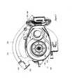
- Figure 1is a perspective illustration of an embodiment of a surface cleaning apparatus
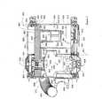
- Figure 2is a cross section taken along line 2-2 in Figure 1 ;
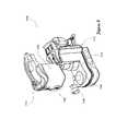
- Figure 3is a perspective illustration of the surface cleaning apparatus of Figure 1 , showing a second openable door in an open configuration;
- Figure 3Ais a side plan view of the surface cleaning apparatus of Figure 1 , showing a second openable door in an open configuration;
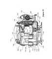
- Figure 3Bis a perspective illustration of the surface cleaning apparatus of Figure 1 showing a first openable door in an open configuration
- Figure 4is a plan view of an alternate embodiment of a surface cleaning apparatus, showing a second openable door in an open configuration
- Figure 4Bis a plan view of another alternate embodiment of a surface cleaning apparatus, showing a second openable door in an open configuration
- Figure 5is a cross section taken along the same line 2-2 through an alternate embodiment of a surface cleaning apparatus
- Figure 6Ais a plan view of an alternate embodiment of a surface cleaning apparatus, showing a first openable door in an open configuration
- Figure 6Bis a perspective illustration of the surface cleaning apparatus of Figure 6A ;
- Figure 7is a perspective illustration of an alternate embodiment of a surface cleaning apparatus
- Figure 8is a perspective illustration of the surface cleaning apparatus of Figure 7 , with its cyclone bin assembly removed;
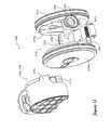
- Figure 9is a perspective illustration of the cyclone bin assembly of Figure 8 ;
- Figure 10is a section view taken along line 10-10 in Figure 7 ;
- Figure 11is a perspective illustration of an alternate embodiment of a surface cleaning apparatus
- Figure 12is a perspective illustration of the surface cleaning apparatus of Figure 11 , with its cyclone bin assembly removed;
- Figure 13is a perspective illustration of the cyclone bin assembly of Figure 12 , with one end wall in an open configuration;
- Figure 14is a perspective illustration of the cyclone bin assembly of Figure 13 , with the one end wall removed;
- Figure 15is a partially exploded view of the surface cleaning apparatus of Figure 11 ;
- Figure 16is a section view taken along line 16-16 in Figure 11 .
- FIG. 1an embodiment of a surface cleaning apparatus 200 is shown.
- the surface cleaning apparatus 200is a hand operable surface cleaning apparatus.
- the surface cleaning apparatus 200is usable in a forward direction of motion, indicated by arrow A in Figure 1 .
- the surface cleaning apparatus 200has a dirty air inlet 202, a clean air outlet 204 (shown in Figure 2 ), and an air flow passage extending therebetween.
- the dirty air inlet 202is provided in a nozzle 206. From the dirty air inlet 202, the airflow passage extends through the nozzle 206, and through an air conduit 208, to a suction and filtration unit 210.
- the clean air outlet 204is provided in the suction and filtration unit 110.
- the air conduit 108includes a wand 214, and a hose 217.
- the suction and filtration unit 210includes a main housing 220.
- a filtration member 224is provided in the main housing 220, and the filtration member 224 is positioned in the airflow passage downstream of the dirty air inlet 202, for removing particulate matter from air flowing through the airflow passage.
- a suction motor 226is also provided in the main housing 220, downstream of the filtration member 224, for drawing air through the airflow passage.
- the suction motor 226may be any suitable type of suction motor.
- the suction motor 226includes a fan 223, and a motor 225.
- the filtration member 224 and suction motor 226are positioned side-by-side. Further, the filtration member 224 extends along an axis 246, and the suction motor extends along an axis 290, and the axes 246, 290 are generally parallel. Further, the filtration member 224 and suction motor 226 are each positioned transverse to the forward direction of motion (indicated by arrow A in Figure 1 ) of the hand surface cleaning apparatus 100.
- the main housing 220includes a central wall 230, a first side wall 232, and a second side wall 234.
- the first side wall 232is pivotally mounted to the central wall 230, and serves as a first openable door 229.
- the second sidewall 234has a first portion 233 adjacent the filtration member 224, and a second portion 235 adjacent the suction motor 226.
- the second sidewall 234is pivotally mounted to the central wall 230, and serves as a second openable door 231. Further, the second portion 235 is removable from the first portion 233.
- an interior wall 237extends within the main housing 220 to separate the suction motor 226 from the filtration member 224, so that fluid communication between the filtration member 224 and the suction motor 226 may generally only occur between a filtration member air outlet 264, and a suction motor air inlet end 239, as will be described in further detail hereinbelow.
- the interior wall 237generally surrounds the suction motor 226 to form a motor housing 227, and is integral with the central wall 230, so that a portion 269 of the motor housing 227 forms part of the housing 220.
- the filtration member 224is a cyclone 244.
- the filtration member 224may be, for example, a filter, such as a filter bag or a foam filter.
- the filtration member 224may include a plurality of cyclone chambers, or a plurality of cyclonic stages.
- the cyclone 244may be of any suitable configuration.
- the cyclone 244includes a cyclone wall 248 (also referred to as an outer wall 248), which is integral with the central wall 230, and together with the central wall 230 defines a cyclone chamber 250. That is, a portion of the cyclone wall 248 forms part of the housing 220.
- the cyclone wall 248is positioned in the main housing 220 such that it is spaced from the second sidewall 234.
- the open first end 252 of the cycloneserves as a dirt outlet for the cyclone 244. Material that is separated form air in the cyclone travels from the dirt outlet to an associated dirt collection chamber 260.
- the dirt chamber 260is preferably positioned in an open volume within the main housing 220. In the embodiment shown, the entire dirt chamber 260 is within an open volume within the main housing 220.
- the dirt collection chamber 260is preferably within the main housing 220, exterior to the cyclone 244 and the suction motor 226.
- the dirt collection chamberextends along a longitudinal axis 261.
- the longitudinal axis 261is preferably parallel to the suction motor axis 290.
- the dirt collection chamber 260is preferably positioned between the cyclone 244 and the suction motor 226. More preferably, at least a portion of the dirt collection chamber 260 surrounds at least a portion of the suction motor 226 and the suction motor housing 227.
- the dirt collection chamber 260may surround all of the suction motor 226, or only a portion of the suction motor 226, and/or all of the suction motor housing 227, or only a portion of the suction motor housing 227.
- the dirt collection chamber 260fully surround the motor 225 of suction motor 226 and the portion suction motor housing 227 that houses the motor 225.
- the dirt collection chamber 260further preferably surrounds at least a portion of the cyclone.
- dirt collection chamber 260extends around approximately one quarter of the cyclone 244. In alternate embodiments, the dirt collection chamber 260 may fully surround the cyclone 244.
- the dirt collection chamber 460partially surrounds the motor 425 of suction motor 426 and the portion suction motor housing 427 that houses the motor 425. Further, the dirt collection chamber 460 partially surrounds the cyclone 444. Particularly, the dirt collection chamber 460 surrounds approximately three quarters of the cyclone 444.
- the dirt collection chamber 460'partially surrounds the motor 425' of suction motor 426' and the portion suction motor housing 427' that houses the motor 425'. Further, the dirt collection chamber 460' partially surrounds the cyclone 444'. Particularly, the dirt collection chamber 460' surrounds approximately one quarter of the cyclone 444'.
- the dirt collection chamber 260has an outer wall 263, and a portion 265 of the outer wall 263 preferably forms part of the main housing 220.
- the cyclone 244further includes a cyclone air inlet (not shown), and a cyclone air outlet 264.
- the cyclone air inletextends from a first end that is in communication with the hose 217 through the central wall 230 of the filtration member main housing 220, to a second end that is in communication with the cyclone chamber 250.
- the cyclone air outlet 264extends along the axis 246, from a first end 270 that is positioned within the cyclone chamber 250, through the lower wall 156, and to a second end 272 (also referred to herein as an outlet 272 of the cyclone air outlet 264) that is in communication with a chamber 241 adjacent the first sidewall 232 of the suction and filtration unit 210.
- a screen 274is preferably mounted over the first end 270 of the cyclone air outlet.
- airflows from the hose 217 into the cyclone chamber 250 through the cyclone air inlet.
- the airflows within the cyclone wall 248 in a cyclonic pattern, and particulate matter is separated from the air.
- the particulate matterexits the cyclone chamber 250 through the open first end 252, and settles in the dirt collection chamber 260.
- the airexits the cyclone chamber 250 through the cyclone air outlet 264, and enters the chamber 241
- the dirt collection chamber 260may be emptied in any suitable manner.
- the second side wall 234is pivotally openable, so that the dirt collection chamber 260 may be opened.
- the surface cleaning apparatusincludes a pre-motor filter 276 positioned downstream of the cyclone 244 and upstream of the suction motor 226.
- the pre-motor filter 276is preferably housed in the chamber 241, is snugly received within the central wall 230, overlies the suction motor 226 and the cyclone 244, and spaced from the first openable door 229.
- the pre-motor filter 276overlies the all of the suction motor 226 and the cyclone 244.
- the pre-motor filtermay overlie only a portion of the suction motor 226 and the cyclone 244.
- the pre-motor filter 276overlies at least half of the suction motor 226 and the cyclone chamber 250, and more preferably, at least 75% of the suction motor 226 and the cyclone chamber 250. More preferably, the pre-motor filter 276 overlies at least half of the suction motor 226 and the cyclone 244, and more preferably, at least 75% of the suction motor 226 and the cyclone 244. Most preferably, as shown, the pre-motor filter has a portion 245 that is centered over the suction motor 226 and a portion 247 that overlies at least half of the cyclone 244. In the embodiment shown, the portion 247 overlies all of the cyclone 244.
- the pre-motor filterhas an upstream side 280 that faces the first sidewall 232 of the main housing 220, and an opposed downstream side 282 that faces the second sidewall 234 of the main housing 220.
- the pre-motor filter 276may be any suitable type of filter.
- the pre-motor filterincludes a foam layer 286 and a felt layer 288.
- the cyclone air outlet 264extends through the pre-motor filter 276, so that air exiting the pre-motor filter 276 is in contact with the upstream side 280 of the pre-motor filter 286.
- the airthen passes through the pre-motor filter 276, towards a suction motor inlet end 239 that faces the downstream side 282 of the pre-motor filter 276. From the suction motor inlet 239, the air passes towards a suction motor outlet end 243, and out of the clean air outlet 204.
- the upstream side 280 of the pre-motor 276is visible.
- the pre-motor filtermay optionally be removed, replaced, or cleaned.
- the pre-motor filter 276is preferably mounted to at least one of the cyclone 244 and the suction motor 226, and the pre-motor filter 276 remains in position when the first openable door 229 is opened.
- the pre-motor filter 276is frictionally mounted to the cyclone air outlet 264.
- the surface cleaning apparatusfurther includes a bleed valve 201.
- the bleed valve 201allows air to flow from the suction motor inlet 239 to the clean air outlet 204 so that the suction motor 226 does not burn out if a clog occurs.
- FIG. 4 and 5a further alternate surface cleaning apparatus 400 is shown.
- the surface cleaning apparatusis similar to the surface cleaning apparatus 200, and like numerals in the surface cleaning apparatus 800 will be used to describe like features as in the surface cleaning apparatus 200, with the first digit incremented to 8.
- the cyclone air outlet 864does not extend through the pre-motor filter 876.
- the upstream side 880 of the pre-motor filter 876faces towards the second sidewall 834 of the housing 820 and faces the cyclone air outlet 864, and the downstream side 882 of the pre-motor filter 876 faces the first sidewall 834. Air passes out of the second end 872 of the cyclone air outlet 864, through the pre-motor filter, and into the chamber 841.
- the suction motor 826has a suction motor inlet duct 853 that extends through the pre-motor filter 876 to the downstream side 882 of the pre-motor filter 876.
- the bleed valve 801is provided in the openable door, and has an air outlet 805 that is within the chamber 841, so that it is in communication with the suction motor air inlet end 839.
- the suction motor inlet 839is visible, and the downstream side 882 of the pre-motor filter 876 is visible.
- FIG. 6A and 6Ba further alternate surface cleaning apparatus 900 is shown.
- the surface cleaning apparatusis similar to the surface cleaning apparatus 200, and like numerals in the surface cleaning apparatus 900 will be used to describe like features as in the surface cleaning apparatus 200, with the first digit incremented to 9.
- the post motor filter 976overlies only the motor (not shown) and the motor housing 927, and does not overlie the cyclone 944.
- the cyclone outlet 964is in communication with the upstream side 980 of the post motor filter 976, which faces towards the first side 232 of the housing 220.
- the downstream side of the post motor filter 976faces the motor inlet end (not shown) and the second side 234 of the housing 920.
- a bleed valve 901extends through the post motor filter 976.
- the surface cleaning apparatus 1100is a hand operable surface cleaning apparatus.
- the surface cleaning apparatusmay be another suitable type of surface cleaning apparatus, including, for example, an upright vacuum cleaner, a canister vacuum cleaner, a stick vacuum cleaner, a wet-dry vacuum cleaner and a carpet extractor.
- the surface cleaning apparatus 1100has a dirty air inlet 1102, a clean air outlet 1104 and an airflow passage extending therebetween.
- the dirty air inlet 1102is the air inlet 1106 of a suction hose connector 1108 that can be connected to the downstream end of, e.g., a flexible suction hose or other type of cleaning accessory tool, including, for example, a wand and a nozzle.
- the airflow passageextends through an air treatment member that can treat the air in a desired manner, including for example removing dirt particles and debris from the air.
- the air treatment membercomprises a cyclone bin assembly 1110.
- the cyclone bin assembly 1110is mounted on a body 1112.
- the air treatment membercan comprise a bag, a filter or other air treating means.
- a suction motor 1114that is mounted within the body 1112 and is in fluid communication with the cyclone bin assembly 1110.
- the dirty air inlet 1102is located toward the front of the surface cleaning apparatus 1100, and the clear air outlet 1104 is located toward the rear.
- cyclone bin assembly 1110includes a cyclone chamber 1118 and a dirt collection chamber 1120.
- the cyclone chamber 1118is bounded by a sidewall 1122, a first end wall 1124 and a second end wall 1126 that are configured to provide an inverted cyclone configuration.
- a tangential air inlet 1128is provided in the sidewall of the cyclone chamber 1118 and is in fluid communication with the air outlet of the hose connector 1108. Air flowing into the cyclone chamber 1118 via the tangential air inlet 1128 can circulate around the interior of the cyclone chamber 1118 and dirt particles and other debris can become disentrained from the circulating air.
- a slot 1132 formed between the sidewall 1122 and the second end wall 1126serves as a cyclone dirt outlet 1132. Debris separated from the air flow in the cyclone chamber 1118 can travel from the cyclone chamber 1118, through the dirt outlet 1132 to the dirt collection chamber 1120.
- Aircan exit the cyclone chamber 1118 via an air outlet.
- the cyclone air outletincludes a vortex finder 1134.
- a removable screen 1136can be positioned over the vortex finder 1134.
- the cyclone chamber 1118extends along a longitudinal cyclone axis 1138. In the example illustrated, the longitudinal cyclone axis 1138 is aligned with the orientation of the vortex finder 1134.
- the dirt collection chamber 1120comprises a sidewall 1140, a first end wall 1142 and an opposing second end wall 1144.
- at least a portion of the dirt collection chamber sidewall 1140is integral with a portion of the cyclone chamber sidewall 1122
- at least a portion of the first cyclone end wall 1124is integral with a portion of the first dirt collection chamber end wall 1142.
- the cyclone bin assembly 1110is optionally detachably connected to the body 1112.
- the cyclone bin assembly 1110is detachably mounted on a platform 1148.
- a releasable latch 1150can be used to secure a front edge of the cyclone bin assembly 1110 to the body 1112.
- a handle 1152is provided on the top of the cyclone bin assembly 1110.
- the handle 1152is configured to be grasped by a user.
- the handle 1152can be used to manipulate the surface cleaning apparatus 1100.
- the handle 1152can be used to carry the cyclone bin assembly 110, for example to position the cyclone bin assembly 1110 above a waste receptacle for emptying.
- the handle 1152is integral with a lid 1154 of the cyclone bin assembly 110.
- the dirt collection chamber sidewall 1140comprises a recess 1214 that is shaped to receive a corresponding portion of the body 1112.
- the recess 1214is shaped to receive a portion of the motor housing 1216 surrounding the suction motor 1114.
- at least a portion of the dirt collection chamber 1120is positioned between the cyclone chamber 1118 and the suction motor 1114.
- at least a portion of the dirt collection chamber 1120surrounds at least a portion of the suction motor 1114 and, if a suction motor housing is provided, the suction motor housing 1216.
- the dirt collection chamber 1120surrounds only a portion of the motor housing 1216.
- the shape of the recess 1214is preferably selected to correspond to the shape of the suction motor housing 1216 so as to maximize the size of the dirt collection chamber for the foot print of the vacuum cleaner. Configuring the dirt collection chamber 1120 to at least partially surround the suction motor housing 216 may help reduce the overall length of the surface cleaning apparatus 1100, and/or may help increase the capacity of the dirt collection chamber 1120.
- the dirt collection chamber 1120also surrounds at least a portion of the cyclone chamber 1118.
- the dirt collection chamber 1120can be configured to completely surround the cyclone chamber 1118.
- the filter chamber 1186is provided downstream from the cyclone air outlet. In the illustrated example, the filter chamber 1186 extends over substantially the entire lower portion of the body 1112 and overlies substantially all of the cyclone chamber 1118, dirt collection chamber 1120 and suction motor 1114.
- a pre-motor filter 1218is provided in the filter chamber 1186 to filter the air before it enters the suction motor inlet 1220.
- the pre-motor filter 1218is sized to cover the entire area of the filter chamber 1186, and overlies substantially all of the cyclone chamber 1118, dirt collection chamber 1120 and suction motor 1114.
- the cross sectional area (in the direction of air flow) of the pre-motor filter 1218is greater than the cross sectional area of the cyclone chamber 1118 and the suction motor 1114.
- the pre-motor filter 1218comprises first and second pre-motor filters 1218a, 1218b.
- the filter chamber 1186comprises an air inlet chamber 1222 on the upstream side 1224 of the pre-motor filter 1218, and an air outlet chamber 1226 on the downstream side 1228 of the pre-motor filter 1218. Air can travel from the air inlet chamber 1222 to the air outlet chamber 1226 by flowing through the air-permeable pre-motor filter 1218. It will be appreciated that the larger the cross sectional area of the upstream face of the filter, the greater the capacity of the filter to filter particulates without the filter becoming clogged. Accordingly, it is preferred to make pre-motor filter 1218 as large as possible. Accordingly, it is preferred that filter chamber 1186 is as large as possible (i.e.
- filter chamber 1186may overlie only a portion of the end face of the cyclone chamber, dirt collection chamber and suction motor but may still provide a larger upstream surface area then is the filter only overlied the cyclone chamber.
- the lower side of the air filtration chambercomprises a filtration chamber end wall 1244.
- the first end wall 1244 of the filter chamber 1186can be openable to allow a user to access the pre-motor filter 1218.
- the filter chamber end wall 1244is pivotally connected to the body 1112 by a hinge 1246 and can pivot to an open position.
- the releasable latch 1150can be used to secure in a closed position.
- the latch 1150can connect the filter chamber end wall 1244 to the cyclone bin assembly 1110.
- the upstream side of pre-motor filter 1218is visible when filter chamber end wall 1244 is in the open position and accordingly, a user may readily detect if the pre-motor filter 1218 requires cleaning or changing.
- the air inlet chamber 1222is fluidly connected to the cyclone chamber air outlet by an inlet conduit 1230 that extends through the pre-motor filter 1218.
- the inlet conduit 1230comprises an extension of a vortex finder insert.
- the air outlet chamber 1226is in fluid communication with the inlet 1220 of the suction motor 1114.
- the pre-motor filter 1218may be supported by a plurality of support ribs 1232 extending through the air outlet chamber 1226. Gaps or cutouts can be provided in the ribs 1232 to allow air to circulate within the air outlet chamber 1226 and flow toward the suction motor inlet 1220.
- a post-motor filter 1236(for example a HEPA filter) can be provided downstream from the suction motor outlet 1116, between the suction motor outlet 1116 and the clean air outlet 1104.
- a detachable grill 1238can be used to retain the post-motor filter 1236 in position, and allow a user to access the post-motor filter 1236 for inspection or replacement.
- the surface cleaning apparatus 2100is a canister vacuum cleaner.
- the surface cleaning apparatus 2100has a dirty air inlet 2102, a clean air outlet 2104 and an airflow passage extending therebetween.
- the dirty air inlet 2102is the air inlet of a suction hose connector 2106 that can be connected to the downstream end of a flexible suction hose or other type of cleaning accessory tool, including, for example, a surface cleaning head, a wand and a nozzle.
- the airflow passageextends through an air treatment member 2108 that can treat the air in a desired manner, including for example removing dirt particles and debris from the air.
- the air treatment member 2108comprises a cyclone bin assembly 2110.
- the air treatment member 2108can comprise a bag, a filter or other air treating means.
- a suction motor 2111( Figure 16 ) is mounted within a body 2112 of the surface cleaning apparatus 2100 and is in fluid communication with the cyclone bin assembly 2110.
- the body 2112 of the surface cleaning apparatus 2100is a rollable, canister-type body that comprises a platform 2114 and two opposing sidewalls 2116a, 2116b that cooperate to define a central cavity 2118.
- the surface cleaning apparatus 2100also comprises two main side wheels 2120a, 2120b, rotatably coupled to the sidewalls 2116a and 2116b, respectively.
- the clean air outlet 2104which is in fluid communication with an outlet of the suction motor 2111, is provided in the body 2112.
- the dirty air inlet 2102is located toward the front 2122 of the surface cleaning apparatus 2100, and the clear air outlet is located toward the rear 2124.
- the body sidewalls 2116a, bare generally circular and cover substantially the entire side faces of the surface cleaning apparatus 2100.
- One main side wheel 2120a, 2120bis coupled to the outer face of each body sidewall 2116a and 2116b, respectively.
- the side wheels 2120a, 2120bmay have a larger diameter 2126 than the body sidewalls 2116a, b and can completely cover the outer faces of the sidewalls 2116a, b.
- each side wheel 2120a, bis rotatably supported by a corresponding axel 2128a, 2128b, which extends from the body sidewalls 2116a and 2116b, respectively.
- the main side wheels 2120a and 2120bare rotatable about a primary axis of rotation 2130. In the illustrated example, the primary axis of rotation 2130 passes through the cyclone bin assembly 2110.
- At least one of the side wheels 120a, bcan be detachable from the body 112.
- side wheel 2120ais detachably coupled to its corresponding axels 2128a by a threaded hub assembly 2132a, and can be removed from the body 2112. Removing the side wheel 2120a from the body 112, or otherwise positioning them in an open configuration, may allow a user to access a variety of components located in compartments between the side wheels 120a and 120b and the corresponding sidewalls 116a and 116b, as explained in greater detail below.
- Figures 12 , 13 , 14 and 16illustrated an example of a cyclone bin assembly 2110 includes a cyclone chamber 2162 and a dirt collection chamber 2164 in accordance with one embodiment.
- the cyclone bin assembly 2110is detachably mounted in the cavity 2118, laterally between the sidewalls 2116a, 2116b and side wheels 2120a, 2120b. Positioning the cyclone bin assembly 2110 in the cavity 2118, between the body sidewalls 2116a, 2116b may help protect the cyclone bin assembly 2110 from side impacts, for example if the surface cleaning apparatus 2100 contacts a piece of furniture or other obstacle.
- the body sidewalls 2116a, 2116bhave a larger cross-sectional area than the cyclone bin assembly 2110. More preferably, the transverse faces of the cyclone bin assembly 2110 are entirely covered by the body sidewalls 2116a, 2116b.
- the cyclone chamber 2162is bounded by a sidewall 2166, a first end wall 2168 and a second end wall 2170.
- a tangential air inlet 2172is provided in the sidewall of the cyclone chamber 2162 and is in fluid communication with the dirty air inlet 2102. Air flowing into the cyclone chamber 2162 via the air inlet can circulate around the interior of the cyclone chamber 2162 and dirt particles and other debris can become disentrained from the circulating air.
- a slot 2180 formed between the sidewall 2166 and the second end wall 2170serves as a cyclone dirt outlet 2180. Debris separated from the air flow in the cyclone chamber 2162 can travel from the cyclone chamber 2162, through the dirt outlet 2180 to the dirt collection chamber 2164.
- Aircan exit the cyclone chamber 2162 via an air outlet.
- the cyclone air outletincludes a vortex finder 2182.
- a removable screen 2183can be positioned over the vortex finder 2182.
- the cyclone chamber 2162extends along a longitudinal cyclone axis 2184.
- the longitudinal cyclone axisis aligned with the orientation of the vortex finder 2182 and is generally transverse to the direction of movement of the surface cleaning apparatus 2100.
- the cyclone chamber 2162has a generally circular cross sectional shape (taken in a plane perpendicular to the cyclone axis) and has a cyclone diameter 2186.
- the dirt collection chamber 2164comprises a sidewall 2174, a first end wall 2176 and an opposing second end wall 2178.
- at least a portion of the dirt collection chamber sidewall 2174is integral with a portion of the cyclone chamber sidewall 2166
- at least a portion of the first cyclone end wall 2168is integral with a portion of the first dirt collection chamber end wall 2176.
- a lower surface 2188 of the cyclone bin assembly 2110is configured to rest on the platform 2114, and the first and second end walls 2168, 2170 of the cyclone bin assembly 2110 are shaped to engage the inner surfaces of the body sidewalls 2116a, 2116b, respectively.
- the upper portion of the cyclone bin(as viewed when installed in the cavity 2118) can have a radius of curvature that generally corresponds to the radius of curvature of the body sidewalls 2116a, 2116b and the side wheels 2120a, 2120b.
- Matching the curvature of the cyclone bin assembly 2110 with the curvature of the side wheels 120a, 120bmay help facilitate mounting of the cyclone bin assembly 2110 within the body 2112, so that the walls of the cyclone bin assembly 2110 do not extend radially beyond the body sidewalls 2116a, 1216b or main side wheels 2120a, 2120b.
- the second dirt collection chamber end wall 2178is preferably pivotally connected to the dirt collection chamber sidewall 2174.
- the second dirt collection chamber end wall 2178can be opened to empty dirt and debris from the interior of the dirt collection chamber 2164.
- the second cyclone end wall 2170is integral with and is openable with the second dirt collection chamber end wall 2178. Opening the second cyclone end wall 2170 can allow dirt and debris to be emptied from the cyclone chamber 2162.
- the second dirt collection chamber sidewall 2178can be retained in the closed position by a releasable latch 2204.
- the screen 2183 and/or the vortex finder 2182can be removable from the cyclone chamber 2162 and can be removed when the second dirt collection chamber end wall 2178 is open.
- the dirt collection chamber sidewall 2174comprises a recess 2206 that is shaped to receive a corresponding portion of the body 2112.
- the platform 2114comprises a generally planar bearing surface 2208 for supporting the cyclone bin assembly 2110.
- the platform 2114also comprises at least a portion of the suction motor housing 2210 surrounding the suction motor 2111.
- the recess 2206 in the dirt collection chamber sidewall 2174is shaped to receive the portion of the motor housing 2210 projecting above the planar bearing surface 2208.
- At least a portion of the dirt collection chamber 2164surrounds at least a portion of the suction motor 2111 and the suction motor housing 2210.
- at least a portion of the dirt collection chamber 2164is positioned between the cyclone chamber 2162 and the suction motor housing 2210 (and the suction motor 2111 therein). Configuring the dirt collection chamber 2164 to at least partially surround the suction motor housing 2210 may help reduce the overall size of the surface cleaning apparatus 2100, and/or may help increase the capacity of the dirt collection chamber 2164.
- the dirt collection chamber 2164also surrounds at least a portion of the cyclone chamber 2162.
- air exiting the cyclone chamber 2162flows to a suction motor inlet 2246 via a filter chamber 2248.
- the filter chamber 2248is provided downstream from the cyclone air outlet.
- the filter chamber 2248comprises a recessed chamber in the body sidewall 2116a that is enclosed by an openable seal plate 2250.
- a sealing gasket 2254is provided at the interface between an annular rim 2252 of the sidewall 2116a and the seal plate 2250 to help provide an air-tight filter chamber 2248.
- the filter chamber 2248extends over substantially the entire sidewall 2116a and overlies substantially all of the transverse cross sectional area of cyclone chamber 2162, dirt collection chamber 2164 and suction motor 2111.
- a pre-motor filter 2256is provided in the filter chamber 2248 to filter the air before it enters the suction motor inlet.
- the pre-motor filter 2256is sized to cover substantially the entire area of the filter chamber 2248, and overlies substantially all of the transverse cross sectional area of the cyclone chamber 2162, dirt collection chamber 2164 and suction motor 2111.
- the pre-motor filter 2256comprises first and second pre-motor filters 2256a, 2256b.
- the filter chamber 2248comprises an air inlet chamber 2258 on the upstream side of the pre-motor filter 256, and an air outlet chamber 2260 on the downstream side of the pre-motor filter 2256. Air can travel from the air inlet chamber 2258 to the air outlet chamber 2260 by flowing through the pre-motor filter 2256.
- the air inlet chamber 2258is fluidly connected to the vortex finder 2182 by an inlet conduit 2262 that extends through a first aperture 2264 in the pre-motor filter 2256.
- the air outlet chamber 2260is in fluid communication with the inlet 2246 of the suction motor 2111.
- the pre-motor filter 2256can be supported by a plurality of support ribs 2266 extending from the sidewall 2116a into the air outlet chamber 2260. Cutouts can be provided in the ribs to allow air to circulate within the air outlet chamber 2266 and flow toward the suction motor inlet 2246.
- the axle 2128a for supporting the side wheelextends through the air filter chamber 2248, a second aperture 2268 in the pre-motor filter 2256 and through an axel aperture 2270 in the seal plate 2250.
- the axle aperture 2270 in the seal plate 2250is configured to provide an air-tight seal against the axel 2128a.
- a sealing gasketcan be provided at the interface between the seal plate 2250 and the axel 2128a. In this configuration the pre-motor filter 2256 surrounds the axel 2128a.
- the seal plate 2250is removable, when the side wheel 2120a is detached, to allow a user to access the pre-motor filter 2256.
- the seal plate 2250can be movably attached to the body 2112, for example pivotally connected to the sidewall 2116a, such that the seal plate 2250 can be opened without being completely detached from the body 2112.
- the seal plate 2250is transparent, or at least partially transparent. Providing a transparent seal plate 2250 may help facilitate visual inspection of the upstream side 2272 of the pre-motor filter 2256 while the seal plate 2250 is in place. When the seal plate 2250 is removed, the pre-motor filter 2256 may be removed, for example for cleaning or replacement.
- a bleed valveis provided to supply clean air to the suction motor inlet.
- a bleed valve air outlet 2278is in fluid communication with the air outlet chamber 2260 and can introduce clean air into the air outlet chamber 2260 downstream from the pre-motor filter 2256. Air introduced by the bleed valve can flow through the cutouts in the supporting ribs 2266, as described above.
- the bleed valvemay be a pressure sensitive valve that is opened when there is a blockage in the air flow path upstream from the suction motor 2111. In the illustrated example, the bleed valve is parallel with the suction motor 2111.
- a bleed valve inlet 2280(see also Figure 11 ) is provided toward the front of the body 2112.
- the enhanced dirt collection chamber constructionmay be used by itself without the enhanced filter chamber design. Alternately, both the enhanced dirt collection chamber construction and the enhanced filter chamber design may be used concurrently as exemplified herein. It will also be appreciated that the cyclone chamber may be of any design and configuration. When either of the enhanced dirt collection chamber construction and/or the enhanced filter chamber design are used, the vacuum cleaner may be of any design and the dirt collection chamber may or may not be removably mounted from the vacuum cleaner.
Landscapes
- Engineering & Computer Science (AREA)
- Mechanical Engineering (AREA)
- Filters For Electric Vacuum Cleaners (AREA)
- Cyclones (AREA)
- Cleaning In General (AREA)
Abstract
Description
- The disclosure relates to surface cleaning apparatuses, such as vacuum cleaners.
- The following is not an admission that anything discussed below is prior art or part of the common general knowledge of persons skilled in the art.
- Various constructions for surface cleaning apparatus such as vacuum cleaners are known. Currently, many surface cleaning apparatus are constructed using at least one cyclonic cleaning stage. The air is drawn into the vacuum cleaner through a dirty air inlet and conveyed to a cyclone inlet. The rotation of the air in the cyclone chamber results in some of the particulate matter in the airflow stream being disentrained from the airflow stream. This material is then collected in a dirt collection chamber, which may be at the bottom of the cyclone chamber or in a dirt collection chamber exterior to the cyclone chamber (see for example
WO2009/026709 andUS 5,078,761 ). One or more additional cyclonic cleaning stages and/or filters may be positioned downstream from the cyclone chamber. - The following summary is provided to introduce the reader to the more detailed discussion to follow. The summary is not intended to limit or define the claims.
- According to one aspect, a hand surface cleaning apparatus is provided that may be operable for an enhanced period of time without a significant reduction is air flow into the dirty air inlet. In accordance with this aspect, a pre-motor filter with enhanced surface area transverse to the direction of air flow is provided.
- Typically, a surface cleaning apparatus such as a hand vacuum cleaner has a pre-motor filter and a post motor filter. The post motor filter may be a HEPA filter. In such a case, the air discharged from the clean air outlet of the unit may be comparable to that discharged from a full size vacuum cleaner. As the HEPA filter is used, the air flow through the unit will decrease and the suction provided by the unit will decrease. This can impact upon the cleaning performance achieved by the vacuum cleaner. To counter this, a larger suction motor may be provided. However, that would increase the hand weight of the unit. A pre-motor filter reduces the level of entrained dirt that will reach the HEPA filter. However, the filter will become clogged with use. Increasing the surface area of the upstream side of the pre-motor filter extends the lifetime of the pre-motor filter and may therefore enhance the life of a post motor filter.
- The pre-motor filter may have an enhanced surface area of its upstream side by configuring the pre-motor filter to have a larger upstream surface area then that of the suction motor inlet end. A pre-motor filter may be positioned in the suction motor casing and may therefore have a diameter that is about the same as the diameter of the fan of the suction motor. By configuring the pre-motor filter to overlie part of one or more additional components of the unit, the surface area of the upstream side is increased.
- For example, a suction motor may be positioned beside a cyclone chamber and extend in the same direction of the cyclone chamber. Accordingly, one end of a cyclone chamber may be adjacent the inlet end of the suction motor (e.g., positioned in about the same plane). The pre-motor filter (preferably a foam filter and more preferably a foam filter with a felt filter downstream thereof) may be configured to overlie part or all of the cyclone chamber as well as part or all of the suction motor. Alternately, or in addition, the pre-motor filter may overlie part of the open volume between the suction motor and the cyclone chamber. If the dirt collection chamber is exterior to the cyclone chamber, e.g., it is positioned to occupy some of the open volume, then the pre-motor filter may alternately or in addition overlie part or all of the dirt collection chamber. Accordingly, a pre-motor filter with an enhanced surface area of the upstream side may be provided without substantially increasing the size of the unit. A filter with an enhanced size may be provided by providing a filter that overlies part or all of two or more of the suction motor, the dirt collection chamber and the cyclone chamber.
- According to this aspect, a surface cleaning apparatus is provided. The hand surface cleaning apparatus comprises an air flow passage extending from a dirty air inlet to a clean air outlet. A suction motor is positioned in the air flow path and has an inlet end and an outlet end. At least one cyclone chamber is positioned in the air flow path and has an associated dirt collection chamber, a cyclone air inlet and a cyclone air outlet. A pre-motor filter is positioned downstream of the cyclone chamber and upstream of the suction motor. The pre-motor filter has an upstream side and a downstream side. The pre-motor filter overlies at least a portion of the suction motor and the cyclone chamber.
- The cyclone chamber and the suction motor may be positioned side by side and may have generally parallel longitudinal axes.
- The pre-motor filter may overlie at least half of the suction motor and the cyclone chamber. The pre-motor filter may overlie at least 75% of the suction motor and the cyclone chamber.
- The pre-motor filter may have a portion that is centered over the suction motor and a portion that overlies at least half of the cyclone chamber.
- The upstream side of the pre-motor filter may face the cyclone air outlet and an inlet duct of the suction motor may extend through the pre-motor filter to the downstream side of the pre-motor filter.
- The cyclone air outlet may extend through the pre-motor filter to the upstream side of the pre-motor filter, and the inlet end of the suction motor may face the downstream side of the pre-motor filter.
- The hand surface cleaning apparatus may further comprising an openable door positioned at a side of the hand vacuum cleaner having the cyclone air outlet and the inlet end of the suction motor. The upstream side of the pre-motor filter may be visible when the door is opened.
- The pre-motor filter may be mounted to at least one of the cyclone chamber and the suction motor and the pre-motor filter may remain in position when the door is opened.
- The pre-motor filter may be spaced from the door and a chamber may be provided between the pre-motor filter and the door.
- Reference is made in the detailed description to the accompanying drawings, in which:
Figure 1 is a perspective illustration of an embodiment of a surface cleaning apparatus;Figure 2 is a cross section taken along line 2-2 inFigure 1 ;Figure 3 is a perspective illustration of the surface cleaning apparatus ofFigure 1 , showing a second openable door in an open configuration;Figure 3A is a side plan view of the surface cleaning apparatus ofFigure 1 , showing a second openable door in an open configuration;Figure 3B is a perspective illustration of the surface cleaning apparatus ofFigure 1 showing a first openable door in an open configuration;Figure 4 is a plan view of an alternate embodiment of a surface cleaning apparatus, showing a second openable door in an open configuration;Figure 4B is a plan view of another alternate embodiment of a surface cleaning apparatus, showing a second openable door in an open configuration;Figure 5 is a cross section taken along the same line 2-2 through an alternate embodiment of a surface cleaning apparatus;Figure 6A is a plan view of an alternate embodiment of a surface cleaning apparatus, showing a first openable door in an open configuration;Figure 6B is a perspective illustration of the surface cleaning apparatus ofFigure 6A ;Figure 7 is a perspective illustration of an alternate embodiment of a surface cleaning apparatus;Figure 8 is a perspective illustration of the surface cleaning apparatus ofFigure 7 , with its cyclone bin assembly removed;Figure 9 is a perspective illustration of the cyclone bin assembly ofFigure 8 ;Figure 10 is a section view taken along line 10-10 inFigure 7 ;Figure 11 is a perspective illustration of an alternate embodiment of a surface cleaning apparatus;Figure 12 is a perspective illustration of the surface cleaning apparatus ofFigure 11 , with its cyclone bin assembly removed;Figure 13 is a perspective illustration of the cyclone bin assembly ofFigure 12 , with one end wall in an open configuration;Figure 14 is a perspective illustration of the cyclone bin assembly ofFigure 13 , with the one end wall removed;Figure 15 is a partially exploded view of the surface cleaning apparatus ofFigure 11 ; andFigure 16 is a section view taken along line 16-16 inFigure 11 .- Referring to
Figure 1 , an embodiment of asurface cleaning apparatus 200 is shown. In this embodiment thesurface cleaning apparatus 200 is a hand operable surface cleaning apparatus. Thesurface cleaning apparatus 200 is usable in a forward direction of motion, indicated by arrow A inFigure 1 . - Referring to
Figure 2 , thesurface cleaning apparatus 200 has adirty air inlet 202, a clean air outlet 204 (shown inFigure 2 ), and an air flow passage extending therebetween. In the embodiment shown, thedirty air inlet 202 is provided in anozzle 206. From thedirty air inlet 202, the airflow passage extends through thenozzle 206, and through anair conduit 208, to a suction andfiltration unit 210. Theclean air outlet 204 is provided in the suction and filtration unit 110. In the embodiment shown, the air conduit 108 includes awand 214, and ahose 217. - Referring now to
Figures 1 and2 , the suction andfiltration unit 210 includes amain housing 220. A filtration member 224 is provided in themain housing 220, and the filtration member 224 is positioned in the airflow passage downstream of thedirty air inlet 202, for removing particulate matter from air flowing through the airflow passage. - A
suction motor 226 is also provided in themain housing 220, downstream of the filtration member 224, for drawing air through the airflow passage. Thesuction motor 226 may be any suitable type of suction motor. In the embodiment shown, thesuction motor 226 includes afan 223, and amotor 225. - In the embodiment shown, the filtration member 224 and
suction motor 226 are positioned side-by-side. Further, the filtration member 224 extends along anaxis 246, and the suction motor extends along anaxis 290, and theaxes suction motor 226 are each positioned transverse to the forward direction of motion (indicated by arrow A inFigure 1 ) of the hand surface cleaning apparatus 100. - Referring to
Figure 1 , in the embodiment shown, themain housing 220 includes acentral wall 230, afirst side wall 232, and asecond side wall 234. Thefirst side wall 232 is pivotally mounted to thecentral wall 230, and serves as a first openable door 229. Thesecond sidewall 234 has afirst portion 233 adjacent the filtration member 224, and asecond portion 235 adjacent thesuction motor 226. Thesecond sidewall 234 is pivotally mounted to thecentral wall 230, and serves as a second openable door 231. Further, thesecond portion 235 is removable from thefirst portion 233. - Referring to
Figure 2 , aninterior wall 237 extends within themain housing 220 to separate thesuction motor 226 from the filtration member 224, so that fluid communication between the filtration member 224 and thesuction motor 226 may generally only occur between a filtrationmember air outlet 264, and a suction motorair inlet end 239, as will be described in further detail hereinbelow. Theinterior wall 237 generally surrounds thesuction motor 226 to form amotor housing 227, and is integral with thecentral wall 230, so that aportion 269 of themotor housing 227 forms part of thehousing 220. - Referring to
Figure 2 , in the embodiment shown, the filtration member 224 is acyclone 244. In alternate embodiments, the filtration member 224 may be, for example, a filter, such as a filter bag or a foam filter. In further alternate embodiments, the filtration member 224 may include a plurality of cyclone chambers, or a plurality of cyclonic stages. - The
cyclone 244 may be of any suitable configuration. Thecyclone 244 includes a cyclone wall 248 (also referred to as an outer wall 248), which is integral with thecentral wall 230, and together with thecentral wall 230 defines acyclone chamber 250. That is, a portion of thecyclone wall 248 forms part of thehousing 220. Afirst end 251 of the cyclone wall 148, which is positioned towards thesecond sidewall 234, defines anopening 252, and an opposedsecond end 254 of the cyclone wall includes asecond end wall 256. Thecyclone wall 248 is positioned in themain housing 220 such that it is spaced from thesecond sidewall 234. - The open
first end 252 of the cyclone serves as a dirt outlet for thecyclone 244. Material that is separated form air in the cyclone travels from the dirt outlet to an associateddirt collection chamber 260. - Referring to
Figures 2 and3 , at least a portion of thedirt chamber 260 is preferably positioned in an open volume within themain housing 220. In the embodiment shown, theentire dirt chamber 260 is within an open volume within themain housing 220. Thedirt collection chamber 260 is preferably within themain housing 220, exterior to thecyclone 244 and thesuction motor 226. The dirt collection chamber extends along alongitudinal axis 261. Thelongitudinal axis 261 is preferably parallel to thesuction motor axis 290. - Referring to
Figures 2 and3 , at least a portion of thedirt collection chamber 260 is preferably positioned between thecyclone 244 and thesuction motor 226. More preferably, at least a portion of thedirt collection chamber 260 surrounds at least a portion of thesuction motor 226 and thesuction motor housing 227. For example, thedirt collection chamber 260 may surround all of thesuction motor 226, or only a portion of thesuction motor 226, and/or all of thesuction motor housing 227, or only a portion of thesuction motor housing 227. As seen most clearly inFigure 3 , in the embodiment shown, thedirt collection chamber 260 fully surround themotor 225 ofsuction motor 226 and the portionsuction motor housing 227 that houses themotor 225. - The
dirt collection chamber 260 further preferably surrounds at least a portion of the cyclone. For example, in the embodiment shown,dirt collection chamber 260 extends around approximately one quarter of thecyclone 244. In alternate embodiments, thedirt collection chamber 260 may fully surround thecyclone 244. - In an alternate embodiment of a
surface cleaning apparatus 400 shown inFigure 4 , wherein like reference numerals are used to refer to like features as inFigures 1 to 3 , with the first digit incremented to 4, thedirt collection chamber 460 partially surrounds the motor 425 ofsuction motor 426 and the portionsuction motor housing 427 that houses the motor 425. Further, thedirt collection chamber 460 partially surrounds thecyclone 444. Particularly, thedirt collection chamber 460 surrounds approximately three quarters of thecyclone 444. In another alternate embodiment of a surface cleaning apparatus 400' shown inFigure 5 , wherein like reference numerals are used to refer to like features as inFigure 4 , with a prime (') after the reference number, similarly to the embodiment ofFigure 4 , the dirt collection chamber 460' partially surrounds the motor 425' of suction motor 426' and the portion suction motor housing 427' that houses the motor 425'. Further, the dirt collection chamber 460' partially surrounds the cyclone 444'. Particularly, the dirt collection chamber 460' surrounds approximately one quarter of the cyclone 444'. - Referring to
Figure 3 , thedirt collection chamber 260 has anouter wall 263, and aportion 265 of theouter wall 263 preferably forms part of themain housing 220. - The
cyclone 244 further includes a cyclone air inlet (not shown), and acyclone air outlet 264. The cyclone air inlet extends from a first end that is in communication with thehose 217 through thecentral wall 230 of the filtration membermain housing 220, to a second end that is in communication with thecyclone chamber 250. Thecyclone air outlet 264 extends along theaxis 246, from a first end 270 that is positioned within thecyclone chamber 250, through the lower wall 156, and to a second end 272 (also referred to herein as anoutlet 272 of the cyclone air outlet 264) that is in communication with achamber 241 adjacent thefirst sidewall 232 of the suction andfiltration unit 210. A screen 274 is preferably mounted over the first end 270 of the cyclone air outlet. - In use, air flows from the
hose 217 into thecyclone chamber 250 through the cyclone air inlet. In thecyclone chamber 250, the air flows within thecyclone wall 248 in a cyclonic pattern, and particulate matter is separated from the air. The particulate matter exits thecyclone chamber 250 through the openfirst end 252, and settles in thedirt collection chamber 260. The air exits thecyclone chamber 250 through thecyclone air outlet 264, and enters thechamber 241 - The
dirt collection chamber 260 may be emptied in any suitable manner. Referring toFigure 3A , in the embodiment shown, thesecond side wall 234 is pivotally openable, so that thedirt collection chamber 260 may be opened. - Referring still to
Figure 2 , the surface cleaning apparatus includes apre-motor filter 276 positioned downstream of thecyclone 244 and upstream of thesuction motor 226. Thepre-motor filter 276 is preferably housed in thechamber 241, is snugly received within thecentral wall 230, overlies thesuction motor 226 and thecyclone 244, and spaced from the first openable door 229. In the embodiment shown, thepre-motor filter 276 overlies the all of thesuction motor 226 and thecyclone 244. In alternate embodiments, the pre-motor filter may overlie only a portion of thesuction motor 226 and thecyclone 244. Preferably, thepre-motor filter 276 overlies at least half of thesuction motor 226 and thecyclone chamber 250, and more preferably, at least 75% of thesuction motor 226 and thecyclone chamber 250. More preferably, thepre-motor filter 276 overlies at least half of thesuction motor 226 and thecyclone 244, and more preferably, at least 75% of thesuction motor 226 and thecyclone 244. Most preferably, as shown, the pre-motor filter has aportion 245 that is centered over thesuction motor 226 and aportion 247 that overlies at least half of thecyclone 244. In the embodiment shown, theportion 247 overlies all of thecyclone 244. - The pre-motor filter has an
upstream side 280 that faces thefirst sidewall 232 of themain housing 220, and an opposeddownstream side 282 that faces thesecond sidewall 234 of themain housing 220. Thepre-motor filter 276 may be any suitable type of filter. Preferably, the pre-motor filter includes afoam layer 286 and a feltlayer 288. - Referring still to
Figure 2 , thecyclone air outlet 264 extends through thepre-motor filter 276, so that air exiting thepre-motor filter 276 is in contact with theupstream side 280 of thepre-motor filter 286. - The air then passes through the
pre-motor filter 276, towards a suctionmotor inlet end 239 that faces thedownstream side 282 of thepre-motor filter 276. From thesuction motor inlet 239, the air passes towards a suctionmotor outlet end 243, and out of theclean air outlet 204. - Preferably, as shown in
Figure 3B , when the first openable door 229 is open, theupstream side 280 of the pre-motor 276 is visible. By opening the openable door 229, the pre-motor filter may optionally be removed, replaced, or cleaned. Further, thepre-motor filter 276 is preferably mounted to at least one of thecyclone 244 and thesuction motor 226, and thepre-motor filter 276 remains in position when the first openable door 229 is opened. For example, as shown, thepre-motor filter 276 is frictionally mounted to thecyclone air outlet 264. - Referring still to
Figure 2 , the surface cleaning apparatus further includes ableed valve 201. Thebleed valve 201 allows air to flow from thesuction motor inlet 239 to theclean air outlet 204 so that thesuction motor 226 does not burn out if a clog occurs. - Referring to
Figures 4 and5 , a further alternatesurface cleaning apparatus 400 is shown. The surface cleaning apparatus is similar to thesurface cleaning apparatus 200, and like numerals in thesurface cleaning apparatus 800 will be used to describe like features as in thesurface cleaning apparatus 200, with the first digit incremented to 8. - In the
surface cleaning apparatus 800, thecyclone air outlet 864 does not extend through thepre-motor filter 876. Theupstream side 880 of thepre-motor filter 876 faces towards thesecond sidewall 834 of thehousing 820 and faces thecyclone air outlet 864, and thedownstream side 882 of thepre-motor filter 876 faces thefirst sidewall 834. Air passes out of thesecond end 872 of thecyclone air outlet 864, through the pre-motor filter, and into thechamber 841. - The
suction motor 826 has a suctionmotor inlet duct 853 that extends through thepre-motor filter 876 to thedownstream side 882 of thepre-motor filter 876. - In this embodiment, the
bleed valve 801 is provided in the openable door, and has anair outlet 805 that is within thechamber 841, so that it is in communication with the suction motorair inlet end 839. - When the openable door is open, the
suction motor inlet 839 is visible, and thedownstream side 882 of thepre-motor filter 876 is visible. - Referring to
Figures 6A and6B , a further alternatesurface cleaning apparatus 900 is shown. The surface cleaning apparatus is similar to thesurface cleaning apparatus 200, and like numerals in thesurface cleaning apparatus 900 will be used to describe like features as in thesurface cleaning apparatus 200, with the first digit incremented to 9. - In the
surface cleaning apparatus 900, the post motor filter 976 overlies only the motor (not shown) and themotor housing 927, and does not overlie the cyclone 944. Thecyclone outlet 964 is in communication with the upstream side 980 of the post motor filter 976, which faces towards thefirst side 232 of thehousing 220. The downstream side of the post motor filter 976 faces the motor inlet end (not shown) and thesecond side 234 of thehousing 920. Ableed valve 901 extends through the post motor filter 976. - Referring to
Figures 7-10 , a further alternatesurface cleaning apparatus 1100 is shown. In the embodiment illustrated, thesurface cleaning apparatus 1100 is a hand operable surface cleaning apparatus. In alternate embodiments, the surface cleaning apparatus may be another suitable type of surface cleaning apparatus, including, for example, an upright vacuum cleaner, a canister vacuum cleaner, a stick vacuum cleaner, a wet-dry vacuum cleaner and a carpet extractor. - Referring to
Figure 10 , thesurface cleaning apparatus 1100 has adirty air inlet 1102, aclean air outlet 1104 and an airflow passage extending therebetween. In the embodiment shown, thedirty air inlet 1102 is the air inlet 1106 of asuction hose connector 1108 that can be connected to the downstream end of, e.g., a flexible suction hose or other type of cleaning accessory tool, including, for example, a wand and a nozzle. From thedirty air inlet 1102, the airflow passage extends through an air treatment member that can treat the air in a desired manner, including for example removing dirt particles and debris from the air. In the illustrated example, the air treatment member comprises acyclone bin assembly 1110. Thecyclone bin assembly 1110 is mounted on abody 1112. Alternatively, or in addition, the air treatment member can comprise a bag, a filter or other air treating means. Asuction motor 1114 that is mounted within thebody 1112 and is in fluid communication with thecyclone bin assembly 1110. - The
clean air outlet 1104, which is in fluid communication with an outlet of thesuction motor 1114, is provided in thebody 1112. In the illustrated example, thedirty air inlet 1102 is located toward the front of thesurface cleaning apparatus 1100, and theclear air outlet 1104 is located toward the rear. - In the illustrated example,
cyclone bin assembly 1110 includes acyclone chamber 1118 and adirt collection chamber 1120. Thecyclone chamber 1118 is bounded by a sidewall 1122, afirst end wall 1124 and asecond end wall 1126 that are configured to provide an inverted cyclone configuration. Atangential air inlet 1128 is provided in the sidewall of thecyclone chamber 1118 and is in fluid communication with the air outlet of thehose connector 1108. Air flowing into thecyclone chamber 1118 via thetangential air inlet 1128 can circulate around the interior of thecyclone chamber 1118 and dirt particles and other debris can become disentrained from the circulating air. - A
slot 1132 formed between the sidewall 1122 and thesecond end wall 1126 serves as acyclone dirt outlet 1132. Debris separated from the air flow in thecyclone chamber 1118 can travel from thecyclone chamber 1118, through thedirt outlet 1132 to thedirt collection chamber 1120. - Air can exit the
cyclone chamber 1118 via an air outlet. In the illustrated example, the cyclone air outlet includes avortex finder 1134. Optionally, aremovable screen 1136 can be positioned over thevortex finder 1134. Thecyclone chamber 1118 extends along alongitudinal cyclone axis 1138. In the example illustrated, thelongitudinal cyclone axis 1138 is aligned with the orientation of thevortex finder 1134. - The
dirt collection chamber 1120 comprises asidewall 1140, afirst end wall 1142 and an opposingsecond end wall 1144. In the illustrated example, at least a portion of the dirtcollection chamber sidewall 1140 is integral with a portion of the cyclone chamber sidewall 1122, and at least a portion of the firstcyclone end wall 1124 is integral with a portion of the first dirt collectionchamber end wall 1142. - Referring to
Figure 8 , thecyclone bin assembly 1110 is optionally detachably connected to thebody 1112. In the example illustrated, thecyclone bin assembly 1110 is detachably mounted on aplatform 1148. Areleasable latch 1150 can be used to secure a front edge of thecyclone bin assembly 1110 to thebody 1112. - Referring to
Figure 7 , ahandle 1152 is provided on the top of thecyclone bin assembly 1110. Thehandle 1152 is configured to be grasped by a user. When thecyclone bin assembly 1110 is mounted on thebody 1112, thehandle 1152 can be used to manipulate thesurface cleaning apparatus 1100. When thecyclone bin assembly 1110 is removed from thebody 1112, thehandle 1152 can be used to carry the cyclone bin assembly 110, for example to position thecyclone bin assembly 1110 above a waste receptacle for emptying. In the illustrated example, thehandle 1152 is integral with alid 1154 of the cyclone bin assembly 110. - Referring to
Figures 9 and10 , the dirtcollection chamber sidewall 1140 comprises arecess 1214 that is shaped to receive a corresponding portion of thebody 1112. In the illustrated example, therecess 1214 is shaped to receive a portion of themotor housing 1216 surrounding thesuction motor 1114. In this example, at least a portion of thedirt collection chamber 1120 is positioned between thecyclone chamber 1118 and thesuction motor 1114. Preferably, at least a portion of thedirt collection chamber 1120 surrounds at least a portion of thesuction motor 1114 and, if a suction motor housing is provided, thesuction motor housing 1216. In the illustrated example, thedirt collection chamber 1120 surrounds only a portion of themotor housing 1216. The shape of therecess 1214 is preferably selected to correspond to the shape of thesuction motor housing 1216 so as to maximize the size of the dirt collection chamber for the foot print of the vacuum cleaner. Configuring thedirt collection chamber 1120 to at least partially surround the suction motor housing 216 may help reduce the overall length of thesurface cleaning apparatus 1100, and/or may help increase the capacity of thedirt collection chamber 1120. - Referring to
Figure 10 , thedirt collection chamber 1120 also surrounds at least a portion of thecyclone chamber 1118. Optionally, thedirt collection chamber 1120 can be configured to completely surround thecyclone chamber 1118. - Air exiting the
cyclone chamber 1118 flows to asuction motor 1114 inlet via anfilter chamber 1186. Thefilter chamber 1186 is provided downstream from the cyclone air outlet. In the illustrated example, thefilter chamber 1186 extends over substantially the entire lower portion of thebody 1112 and overlies substantially all of thecyclone chamber 1118,dirt collection chamber 1120 andsuction motor 1114. - A
pre-motor filter 1218 is provided in thefilter chamber 1186 to filter the air before it enters thesuction motor inlet 1220. Thepre-motor filter 1218 is sized to cover the entire area of thefilter chamber 1186, and overlies substantially all of thecyclone chamber 1118,dirt collection chamber 1120 andsuction motor 1114. Preferably, the cross sectional area (in the direction of air flow) of thepre-motor filter 1218 is greater than the cross sectional area of thecyclone chamber 1118 and thesuction motor 1114. In the illustrated example, thepre-motor filter 1218 comprises first and secondpre-motor filters filter chamber 1186 comprises anair inlet chamber 1222 on theupstream side 1224 of thepre-motor filter 1218, and an air outlet chamber 1226 on thedownstream side 1228 of thepre-motor filter 1218. Air can travel from theair inlet chamber 1222 to the air outlet chamber 1226 by flowing through the air-permeablepre-motor filter 1218. It will be appreciated that the larger the cross sectional area of the upstream face of the filter, the greater the capacity of the filter to filter particulates without the filter becoming clogged. Accordingly, it is preferred to makepre-motor filter 1218 as large as possible. Accordingly, it is preferred thatfilter chamber 1186 is as large as possible (i.e. it overlies all of an end face of the cyclone chamber, dirt collection chamber and suction motor) and that thepre-motor filter 1218 extends over the full transverse extent offilter chamber 1186. It will be appreciated that thefilter chamber 1186 may overlie only a portion of the end face of the cyclone chamber, dirt collection chamber and suction motor but may still provide a larger upstream surface area then is the filter only overlied the cyclone chamber. - The lower side of the air filtration chamber comprises a filtration
chamber end wall 1244. Optionally, thefirst end wall 1244 of thefilter chamber 1186 can be openable to allow a user to access thepre-motor filter 1218. In the illustrated example, the filterchamber end wall 1244 is pivotally connected to thebody 1112 by a hinge 1246 and can pivot to an open position. Thereleasable latch 1150 can be used to secure in a closed position. Thelatch 1150 can connect the filterchamber end wall 1244 to thecyclone bin assembly 1110. As exemplified and discussed hereafter, the upstream side ofpre-motor filter 1218 is visible when filterchamber end wall 1244 is in the open position and accordingly, a user may readily detect if thepre-motor filter 1218 requires cleaning or changing. - The
air inlet chamber 1222 is fluidly connected to the cyclone chamber air outlet by aninlet conduit 1230 that extends through thepre-motor filter 1218. In the illustrated example theinlet conduit 1230 comprises an extension of a vortex finder insert. The air outlet chamber 1226 is in fluid communication with theinlet 1220 of thesuction motor 1114. Thepre-motor filter 1218 may be supported by a plurality of support ribs 1232 extending through the air outlet chamber 1226. Gaps or cutouts can be provided in the ribs 1232 to allow air to circulate within the air outlet chamber 1226 and flow toward thesuction motor inlet 1220. From thesuction motor inlet 1220, the air is drawn through thesuction motor 1114 and ejected via a suction motor outlet 1116. Optionally, a post-motor filter 1236 (for example a HEPA filter) can be provided downstream from the suction motor outlet 1116, between the suction motor outlet 1116 and theclean air outlet 1104. Adetachable grill 1238 can be used to retain thepost-motor filter 1236 in position, and allow a user to access thepost-motor filter 1236 for inspection or replacement. - Referring to
Figures 11 to 16 , another embodiment of asurface cleaning apparatus 2100 is shown. In the embodiment illustrated, thesurface cleaning apparatus 2100 is a canister vacuum cleaner. Thesurface cleaning apparatus 2100 has adirty air inlet 2102, aclean air outlet 2104 and an airflow passage extending therebetween. In the embodiment shown, thedirty air inlet 2102 is the air inlet of asuction hose connector 2106 that can be connected to the downstream end of a flexible suction hose or other type of cleaning accessory tool, including, for example, a surface cleaning head, a wand and a nozzle. From thedirty air inlet 2102, the airflow passage extends through an air treatment member 2108 that can treat the air in a desired manner, including for example removing dirt particles and debris from the air. In the illustrated example, the air treatment member 2108 comprises acyclone bin assembly 2110. Alternatively, or in addition, the air treatment member 2108 can comprise a bag, a filter or other air treating means. A suction motor 2111 (Figure 16 ) is mounted within abody 2112 of thesurface cleaning apparatus 2100 and is in fluid communication with thecyclone bin assembly 2110. In the illustrated example, thebody 2112 of thesurface cleaning apparatus 2100 is a rollable, canister-type body that comprises aplatform 2114 and two opposing sidewalls 2116a, 2116b that cooperate to define acentral cavity 2118. Thesurface cleaning apparatus 2100 also comprises twomain side wheels sidewalls - The
clean air outlet 2104, which is in fluid communication with an outlet of thesuction motor 2111, is provided in thebody 2112. In the illustrated example, thedirty air inlet 2102 is located toward thefront 2122 of thesurface cleaning apparatus 2100, and the clear air outlet is located toward the rear 2124. - In the illustrated example, the body sidewalls 2116a, b are generally circular and cover substantially the entire side faces of the
surface cleaning apparatus 2100. Onemain side wheel body sidewall side wheels larger diameter 2126 than the body sidewalls 2116a, b and can completely cover the outer faces of the sidewalls 2116a, b. Referring toFigure 16 , eachside wheel 2120a, b is rotatably supported by a correspondingaxel body sidewalls main side wheels rotation 2130. In the illustrated example, the primary axis ofrotation 2130 passes through thecyclone bin assembly 2110. - Optionally, at least one of the side wheels 120a, b can be detachable from the body 112. Referring to
Figure 15 , in the illustratedexample side wheel 2120a is detachably coupled to itscorresponding axels 2128a by a threaded hub assembly 2132a, and can be removed from thebody 2112. Removing theside wheel 2120a from the body 112, or otherwise positioning them in an open configuration, may allow a user to access a variety of components located in compartments between the side wheels 120a and 120b and the corresponding sidewalls 116a and 116b, as explained in greater detail below. Figures 12 ,13 ,14 and16 illustrated an example of acyclone bin assembly 2110 includes acyclone chamber 2162 and adirt collection chamber 2164 in accordance with one embodiment. Thecyclone bin assembly 2110 is detachably mounted in thecavity 2118, laterally between the sidewalls 2116a, 2116b andside wheels cyclone bin assembly 2110 in thecavity 2118, between the body sidewalls 2116a, 2116b may help protect thecyclone bin assembly 2110 from side impacts, for example if thesurface cleaning apparatus 2100 contacts a piece of furniture or other obstacle. Preferably, the body sidewalls 2116a, 2116b have a larger cross-sectional area than thecyclone bin assembly 2110. More preferably, the transverse faces of thecyclone bin assembly 2110 are entirely covered by the body sidewalls 2116a, 2116b.- In the illustrated example, the
cyclone chamber 2162 is bounded by asidewall 2166, afirst end wall 2168 and asecond end wall 2170. Atangential air inlet 2172 is provided in the sidewall of thecyclone chamber 2162 and is in fluid communication with thedirty air inlet 2102. Air flowing into thecyclone chamber 2162 via the air inlet can circulate around the interior of thecyclone chamber 2162 and dirt particles and other debris can become disentrained from the circulating air. - A
slot 2180 formed between thesidewall 2166 and thesecond end wall 2170 serves as acyclone dirt outlet 2180. Debris separated from the air flow in thecyclone chamber 2162 can travel from thecyclone chamber 2162, through thedirt outlet 2180 to thedirt collection chamber 2164. - Air can exit the
cyclone chamber 2162 via an air outlet. In the illustrated example, the cyclone air outlet includes avortex finder 2182. Optionally, aremovable screen 2183 can be positioned over thevortex finder 2182. Thecyclone chamber 2162 extends along alongitudinal cyclone axis 2184. In the example illustrated, the longitudinal cyclone axis is aligned with the orientation of thevortex finder 2182 and is generally transverse to the direction of movement of thesurface cleaning apparatus 2100. Thecyclone chamber 2162 has a generally circular cross sectional shape (taken in a plane perpendicular to the cyclone axis) and has acyclone diameter 2186. - The
dirt collection chamber 2164 comprises asidewall 2174, afirst end wall 2176 and an opposingsecond end wall 2178. In the illustrated example, at least a portion of the dirtcollection chamber sidewall 2174 is integral with a portion of thecyclone chamber sidewall 2166, and at least a portion of the firstcyclone end wall 2168 is integral with a portion of the first dirt collectionchamber end wall 2176. - Referring to
Figures 12 and14 , alower surface 2188 of thecyclone bin assembly 2110 is configured to rest on theplatform 2114, and the first andsecond end walls cyclone bin assembly 2110 are shaped to engage the inner surfaces of the body sidewalls 2116a, 2116b, respectively. The upper portion of the cyclone bin (as viewed when installed in the cavity 2118) can have a radius of curvature that generally corresponds to the radius of curvature of the body sidewalls 2116a, 2116b and theside wheels cyclone bin assembly 2110 with the curvature of the side wheels 120a, 120b may help facilitate mounting of thecyclone bin assembly 2110 within thebody 2112, so that the walls of thecyclone bin assembly 2110 do not extend radially beyond the body sidewalls 2116a, 1216b ormain side wheels - Referring to
Figure 13 , the second dirt collectionchamber end wall 2178 is preferably pivotally connected to the dirtcollection chamber sidewall 2174. The second dirt collectionchamber end wall 2178 can be opened to empty dirt and debris from the interior of thedirt collection chamber 2164. Optionally, the secondcyclone end wall 2170 is integral with and is openable with the second dirt collectionchamber end wall 2178. Opening the secondcyclone end wall 2170 can allow dirt and debris to be emptied from thecyclone chamber 2162. The second dirtcollection chamber sidewall 2178 can be retained in the closed position by areleasable latch 2204. Optionally, thescreen 2183 and/or thevortex finder 2182 can be removable from thecyclone chamber 2162 and can be removed when the second dirt collectionchamber end wall 2178 is open. - Referring to
Figures 13 and14 , the dirtcollection chamber sidewall 2174 comprises arecess 2206 that is shaped to receive a corresponding portion of thebody 2112. Referring toFigure 12 , in the illustrated example, theplatform 2114 comprises a generallyplanar bearing surface 2208 for supporting thecyclone bin assembly 2110. Theplatform 2114 also comprises at least a portion of thesuction motor housing 2210 surrounding thesuction motor 2111. In this example, therecess 2206 in the dirtcollection chamber sidewall 2174 is shaped to receive the portion of themotor housing 2210 projecting above theplanar bearing surface 2208. - Preferably, at least a portion of the
dirt collection chamber 2164 surrounds at least a portion of thesuction motor 2111 and thesuction motor housing 2210. In this example, at least a portion of thedirt collection chamber 2164 is positioned between thecyclone chamber 2162 and the suction motor housing 2210 (and thesuction motor 2111 therein). Configuring thedirt collection chamber 2164 to at least partially surround thesuction motor housing 2210 may help reduce the overall size of thesurface cleaning apparatus 2100, and/or may help increase the capacity of thedirt collection chamber 2164. Thedirt collection chamber 2164 also surrounds at least a portion of thecyclone chamber 2162. - Referring to
Figures 15 and16 , air exiting thecyclone chamber 2162 flows to asuction motor inlet 2246 via afilter chamber 2248. Thefilter chamber 2248 is provided downstream from the cyclone air outlet. In the illustrated example, thefilter chamber 2248 comprises a recessed chamber in thebody sidewall 2116a that is enclosed by anopenable seal plate 2250. A sealinggasket 2254 is provided at the interface between anannular rim 2252 of thesidewall 2116a and theseal plate 2250 to help provide an air-tight filter chamber 2248. In the illustrated example, thefilter chamber 2248 extends over substantially theentire sidewall 2116a and overlies substantially all of the transverse cross sectional area ofcyclone chamber 2162,dirt collection chamber 2164 andsuction motor 2111. - A
pre-motor filter 2256 is provided in thefilter chamber 2248 to filter the air before it enters the suction motor inlet. Thepre-motor filter 2256 is sized to cover substantially the entire area of thefilter chamber 2248, and overlies substantially all of the transverse cross sectional area of thecyclone chamber 2162,dirt collection chamber 2164 andsuction motor 2111. In the illustrated example, thepre-motor filter 2256 comprises first and secondpre-motor filters filter chamber 2248 comprises anair inlet chamber 2258 on the upstream side of thepre-motor filter 256, and anair outlet chamber 2260 on the downstream side of thepre-motor filter 2256. Air can travel from theair inlet chamber 2258 to theair outlet chamber 2260 by flowing through thepre-motor filter 2256. - The
air inlet chamber 2258 is fluidly connected to thevortex finder 2182 by aninlet conduit 2262 that extends through afirst aperture 2264 in thepre-motor filter 2256. Theair outlet chamber 2260 is in fluid communication with theinlet 2246 of thesuction motor 2111. Thepre-motor filter 2256 can be supported by a plurality ofsupport ribs 2266 extending from thesidewall 2116a into theair outlet chamber 2260. Cutouts can be provided in the ribs to allow air to circulate within theair outlet chamber 2266 and flow toward thesuction motor inlet 2246. - In the illustrated example, the
axle 2128a for supporting the side wheel extends through theair filter chamber 2248, asecond aperture 2268 in thepre-motor filter 2256 and through anaxel aperture 2270 in theseal plate 2250. Theaxle aperture 2270 in theseal plate 2250 is configured to provide an air-tight seal against theaxel 2128a. Optionally, a sealing gasket can be provided at the interface between theseal plate 2250 and theaxel 2128a. In this configuration thepre-motor filter 2256 surrounds theaxel 2128a. - In the illustrated example, the
seal plate 2250 is removable, when theside wheel 2120a is detached, to allow a user to access thepre-motor filter 2256. Alternatively, instead of being removable, theseal plate 2250 can be movably attached to thebody 2112, for example pivotally connected to thesidewall 2116a, such that theseal plate 2250 can be opened without being completely detached from thebody 2112. - Preferably, the
seal plate 2250 is transparent, or at least partially transparent. Providing atransparent seal plate 2250 may help facilitate visual inspection of theupstream side 2272 of thepre-motor filter 2256 while theseal plate 2250 is in place. When theseal plate 2250 is removed, thepre-motor filter 2256 may be removed, for example for cleaning or replacement. - A bleed valve is provided to supply clean air to the suction motor inlet. In the illustrated example a bleed
valve air outlet 2278 is in fluid communication with theair outlet chamber 2260 and can introduce clean air into theair outlet chamber 2260 downstream from thepre-motor filter 2256. Air introduced by the bleed valve can flow through the cutouts in the supportingribs 2266, as described above. The bleed valve may be a pressure sensitive valve that is opened when there is a blockage in the air flow path upstream from thesuction motor 2111. In the illustrated example, the bleed valve is parallel with thesuction motor 2111. A bleed valve inlet 2280 (see alsoFigure 11 ) is provided toward the front of thebody 2112. - It will be appreciated that, in one embodiment, the enhanced dirt collection chamber construction may be used by itself without the enhanced filter chamber design. Alternately, both the enhanced dirt collection chamber construction and the enhanced filter chamber design may be used concurrently as exemplified herein. It will also be appreciated that the cyclone chamber may be of any design and configuration. When either of the enhanced dirt collection chamber construction and/or the enhanced filter chamber design are used, the vacuum cleaner may be of any design and the dirt collection chamber may or may not be removably mounted from the vacuum cleaner.
- Various apparatuses or methods are described above to provide an example of each claimed invention. No example described above limits any claimed invention and any claimed invention may cover processes or apparatuses that are not described above. The claimed inventions are not limited to apparatuses or processes having all of the features of any one apparatus or process described above or to features common to multiple or all of the apparatuses described above.
Claims (12)
- A surface cleaning apparatus (200) comprising:(a) an air flow passage extending from a dirty air inlet (202) to a clean air outlet (204);(b) a suction motor (226) positioned in the air flow path and having an inlet end (239) and an outlet end (243);(c) at least one cyclone chamber (250) positioned in the air flow path and having an associated dirt collection chamber (260), a cyclone air inlet and a cyclone air outlet (264); and,(d) a pre-motor filter (276) positioned downstream of the cyclone chamber (250) and upstream of the suction motor (226), the pre-motor filter having an upstream side and a downstream side, wherein the pre-motor filter (276) overlies at least a portion of the suction motor (226) and the cyclone chamber (250).
- The surface cleaning apparatus of claim 1 wherein the cyclone chamber (250) and the suction motor (226) are positioned side by side and have generally parallel longitudinal axes.
- The surface cleaning apparatus of claim 1 wherein the pre-motor filter (276) overlies at least half of the suction motor (226) and the cyclone chamber (250).
- The surface cleaning apparatus of claim 1 wherein the pre-motor filter (276) overlies at least 75% of the suction motor and the cyclone chamber.
- The surface cleaning apparatus of claim 1 wherein the dirt collection chamber (260) is exterior to the cyclone chamber (250) and the pre-motor filter (276) overlies at least half of the suction motor (226), the cyclone chamber (250) and the dirt collection chamber (260).
- The surface cleaning apparatus of claim 1 wherein the dirt collection chamber (260) is exterior to the cyclone chamber (250) and the pre-motor filter (276) overlies at least 75% of the suction motor, the cyclone chamber and the dirt collection chamber
- The surface cleaning apparatus of claim 1 wherein the pre-motor filter (276) has a portion that is centered over the suction motor and a portion that overlies at least half of the cyclone chamber.
- The surface cleaning apparatus of claim 1 wherein the upstream side of the pre-motor filter faces the cyclone air outlet and an inlet duct (853) of the suction motor extends through the pre-motor filter to the downstream side (282) of the pre-motor filter.
- The surface cleaning apparatus of claim 1 wherein the cyclone air outlet (264) extends through the pre-motor filter to the upstream side (280) of the pre-motor filter and the inlet end (239) of the suction motor faces the downstream side (282) of the pre-motor filter.
- The surface cleaning apparatus of claim 1 further comprising an openable door (229) positioned at a side of the surface cleaning apparatus having the cyclone air outlet (264) and the inlet end (853) of the suction motor wherein the upstream side of the pre-motor filter is visible when the door (229) is opened.
- The surface cleaning apparatus of claim 10 wherein the pre-motor filter (276) is mounted to at least one of the cyclone chamber (250) and the suction motor (226) and the pre-motor filter (276) remains in position when the door (229) is opened.
- The surface cleaning apparatus of claim 10 wherein the pre-motor filter is spaced from the door (229) and a chamber is provided between the pre-motor filter (276) and the door (229).
Applications Claiming Priority (2)
| Application Number | Priority Date | Filing Date | Title |
|---|---|---|---|
| US12/722,705US8578555B2 (en) | 2010-03-12 | 2010-03-12 | Surface cleaning apparatus |
| US13/039,376US9265395B2 (en) | 2010-03-12 | 2011-03-03 | Surface cleaning apparatus |
Publications (3)
| Publication Number | Publication Date |
|---|---|
| EP2364630A2true EP2364630A2 (en) | 2011-09-14 |
| EP2364630A3 EP2364630A3 (en) | 2012-06-06 |
| EP2364630B1 EP2364630B1 (en) | 2016-03-09 |
Family
ID=44558524
Family Applications (1)
| Application Number | Title | Priority Date | Filing Date |
|---|---|---|---|
| EP11157649.2AActiveEP2364630B1 (en) | 2010-03-12 | 2011-03-10 | Surface cleaning apparatus |
Country Status (3)
| Country | Link |
|---|---|
| US (3) | US9265395B2 (en) |
| EP (1) | EP2364630B1 (en) |
| CN (1) | CN102188209B (en) |
Cited By (2)
| Publication number | Priority date | Publication date | Assignee | Title |
|---|---|---|---|---|
| CN105072965A (en)* | 2013-02-28 | 2015-11-18 | 奥马克罗知识产权有限公司 | Surface cleaning apparatus |
| EP3209180B1 (en) | 2014-10-22 | 2018-08-15 | Dyson Technology Limited | Vacuum cleaner with motor between separation stages |
Families Citing this family (53)
| Publication number | Priority date | Publication date | Assignee | Title |
|---|---|---|---|---|
| US12220099B2 (en) | 2006-12-12 | 2025-02-11 | Omachron Intellectual Property Inc. | Surface cleaning apparatus |
| US11690489B2 (en) | 2009-03-13 | 2023-07-04 | Omachron Intellectual Property Inc. | Surface cleaning apparatus with an external dirt chamber |
| US10667663B2 (en)* | 2018-03-27 | 2020-06-02 | Omachron Intellectual Property Inc. | Surface cleaning apparatus with an arrester plate having a variable gap |
| US11229340B2 (en) | 2010-03-12 | 2022-01-25 | Omachron Intellectual Property Inc. | Surface cleaning apparatus with an arrester plate having a variable gap |
| GB2503257B (en)* | 2012-06-20 | 2014-12-17 | Dyson Technology Ltd | A cleaning appliance |
| GB2503254B (en) | 2012-06-20 | 2014-12-17 | Dyson Technology Ltd | A cleaning appliance |
| GB2503251C (en) | 2012-06-20 | 2015-07-15 | Dyson Technology Ltd | A self righting cleaning appliance |
| GB2503255B (en) | 2012-06-20 | 2014-10-15 | Dyson Technology Ltd | A cleaning appliance |
| GB2503253B (en) | 2012-06-20 | 2014-10-15 | Dyson Technology Ltd | A cleaning appliance |
| GB2503252B (en) | 2012-06-20 | 2014-12-17 | Dyson Technology Ltd | A self righting cleaning appliance |
| GB2503670B (en) | 2012-07-03 | 2014-12-10 | Dyson Technology Ltd | Method of preheating a brushless motor |
| GB2503671B (en) | 2012-07-03 | 2014-12-17 | Dyson Technology Ltd | Control of a brushless motor |
| JP6334913B2 (en)* | 2013-12-24 | 2018-05-30 | 東芝ライフスタイル株式会社 | Electric vacuum cleaner |
| EP3125736B1 (en) | 2014-04-04 | 2018-06-13 | Techtronic Industries Company Limited | Vaccum cleaner |
| US9962049B2 (en)* | 2014-06-06 | 2018-05-08 | Sharkninja Operating Llc | Surface cleaning apparatus |
| EP3209175B1 (en) | 2014-10-22 | 2023-01-04 | Techtronic Industries Co. Ltd. | Handheld vacuum cleaner |
| US10022027B2 (en) | 2014-12-17 | 2018-07-17 | Omachron Intellectual Property Inc. | All in the head surface cleaning apparatus |
| US9901229B2 (en)* | 2014-12-17 | 2018-02-27 | Omachron Intellectual Property Inc. | All in the head surface cleaning apparatus |
| US9885196B2 (en) | 2015-01-26 | 2018-02-06 | Hayward Industries, Inc. | Pool cleaner power coupling |
| US9909333B2 (en) | 2015-01-26 | 2018-03-06 | Hayward Industries, Inc. | Swimming pool cleaner with hydrocyclonic particle separator and/or six-roller drive system |
| US10786126B2 (en) | 2015-11-10 | 2020-09-29 | Techtronic Industries Co. Ltd. | Handheld vacuum cleaner |
| TWI641353B (en) | 2016-02-29 | 2018-11-21 | Lg電子股份有限公司 | Vacuum cleaner |
| TWI664944B (en) | 2016-02-29 | 2019-07-11 | Lg電子股份有限公司 | Vacuum cleaner |
| CA170178S (en)* | 2016-03-04 | 2017-06-01 | Dyson Technology Ltd | Vacuum cleaner handle |
| CA170186S (en)* | 2016-03-04 | 2017-06-01 | Dyson Technology Ltd | Vacuum cleaner handle |
| CA170182S (en) | 2016-03-04 | 2017-06-01 | Dyson Technology Ltd | Vacuum cleaner handle |
| CA170187S (en)* | 2016-03-04 | 2017-06-01 | Dyson Technology Ltd | Vacuum cleaner connector |
| CA170184S (en)* | 2016-03-04 | 2017-06-01 | Dyson Technology Ltd | Vacuum cleaner handle |
| CA170188S (en) | 2016-03-04 | 2017-06-01 | Dyson Technology Ltd | Vacuum cleaner handle |
| CA170179S (en) | 2016-03-04 | 2017-06-01 | Dyson Technology Ltd | Vacuum cleaner handle |
| CA170180S (en)* | 2016-03-04 | 2017-06-01 | Dyson Technology Ltd | Vacuum cleaner connector |
| DE112017001802T5 (en)* | 2016-03-31 | 2019-01-03 | Lg Electronics Inc. | cleaning device |
| USD838067S1 (en)* | 2016-08-26 | 2019-01-08 | Tti (Macao Commercial Offshore) Limited | Handheld vacuum cleaner |
| US11285495B2 (en)* | 2016-12-27 | 2022-03-29 | Omachron Intellectual Property Inc. | Multistage cyclone and surface cleaning apparatus having same |
| US9885194B1 (en) | 2017-05-11 | 2018-02-06 | Hayward Industries, Inc. | Pool cleaner impeller subassembly |
| US10156083B2 (en) | 2017-05-11 | 2018-12-18 | Hayward Industries, Inc. | Pool cleaner power coupling |
| US9896858B1 (en) | 2017-05-11 | 2018-02-20 | Hayward Industries, Inc. | Hydrocyclonic pool cleaner |
| GB2598506B (en) | 2017-06-19 | 2022-06-08 | Techtronic Floor Care Tech Ltd | A dirt separation device |
| AU2017420074B2 (en) | 2017-06-19 | 2024-05-30 | Techtronic Cordless Gp | Surface cleaning apparatus |
| CN209003807U (en)* | 2017-06-28 | 2019-06-21 | 苏州宝时得电动工具有限公司 | Hand-held cleaners and dust catcher sub-assembly |
| US11745190B2 (en) | 2019-01-23 | 2023-09-05 | Omachron Intellectual Property Inc. | Surface cleaning apparatus |
| EP3684237B1 (en) | 2017-09-22 | 2023-07-19 | SharkNinja Operating LLC | Hand-held surface cleaning device |
| GB2569569B (en) | 2017-12-20 | 2021-04-21 | Dyson Technology Ltd | A filter assembly |
| US11478116B2 (en) | 2018-01-15 | 2022-10-25 | Omachron Intellectual Property Inc | Surface cleaning apparatus |
| US10791897B2 (en)* | 2018-03-27 | 2020-10-06 | Omachron Intellectual Property Inc. | Surface cleaning apparatus with dirt arrester having an axial step |
| KR102327196B1 (en)* | 2018-05-03 | 2021-11-17 | 엘지전자 주식회사 | Cleaner |
| US10932634B2 (en)* | 2018-05-30 | 2021-03-02 | Omachron Intellectual Property Inc. | Surface cleaning apparatus |
| US10827889B2 (en) | 2018-05-30 | 2020-11-10 | Omachron Intellectual Property Inc. | Surface cleaning apparatus |
| CA3116593A1 (en)* | 2018-10-22 | 2020-04-30 | Omachron Intellectual Property Inc. | Air treatment apparatus |
| US11350806B2 (en) | 2020-01-03 | 2022-06-07 | Techtronic Cordless Gp | Handheld vacuum cleaner |
| AU2021237991B2 (en) | 2020-03-18 | 2024-08-01 | Omachron Intellectual Property Inc. | Surface cleaning apparatus with removable air treatment member assembly |
| US12239282B2 (en) | 2020-06-24 | 2025-03-04 | Milwaukee Electric Tool Corporation | Vacuum cleaner with liquid retention |
| DE102020122626A1 (en)* | 2020-08-31 | 2022-03-03 | Miele & Cie. Kg | Bagless vacuum cleaner |
Citations (2)
| Publication number | Priority date | Publication date | Assignee | Title |
|---|---|---|---|---|
| US5078761A (en) | 1990-07-06 | 1992-01-07 | Notetry Limited | Shroud |
| WO2009026709A1 (en) | 2007-08-29 | 2009-03-05 | Gbd Corp. | Cyclonic surface cleaning apparatus with externally positioned dirt chamber |
Family Cites Families (304)
| Publication number | Priority date | Publication date | Assignee | Title |
|---|---|---|---|---|
| FR357191A (en) | 1904-08-31 | 1905-12-20 | Kakao-Compagnie Theodor Reichardt G. M. B. H. | Apparatus for screening powdery materials |
| US1600762A (en) | 1926-06-28 | 1926-09-21 | Hawley Charles Gilbert | Process of separation and apparatus therefor |
| US1797812A (en) | 1928-09-04 | 1931-03-24 | Ass Lead Mfg Ltd | Apparatus for separating suspended matter from fluids |
| US1937765A (en) | 1930-10-15 | 1933-12-05 | Quadrex Corp | Vacuum cleaner |
| US2152114A (en) | 1931-08-17 | 1939-03-28 | Hermannus Van Tongeren | Dust separator |
| GB374382A (en) | 1931-12-31 | 1932-06-09 | William Alexander | Improvements in appliances for centrifugally purifying gases, vapours and steam |
| BE406007A (en) | 1933-08-10 | |||
| US2080697A (en) | 1934-10-01 | 1937-05-18 | George M Clark | Matrix forming and drying machine |
| US2542634A (en) | 1947-11-29 | 1951-02-20 | Apex Electrical Mfg Co | Dust separator |
| US2678110A (en) | 1951-02-12 | 1954-05-11 | Walter M Madsen | Cyclone separator |
| GB700791A (en) | 1951-08-03 | 1953-12-09 | English Electric Co Ltd | Improvements in and relating to dust separators |
| BE515137A (en) | 1951-11-04 | |||
| US2981369A (en) | 1951-11-23 | 1961-04-25 | Bituminous Coal Research | Vortical whirl separator |
| US2731102A (en) | 1952-05-09 | 1956-01-17 | Fram Corp | Apparatus for removing heavy dust from air |
| GB796886A (en) | 1955-01-20 | 1958-06-18 | Walter Jordan | Gas separator for fuel decanting installations |
| US2917131A (en) | 1955-04-11 | 1959-12-15 | Shell Dev | Cyclone separator |
| US2913111A (en) | 1955-05-13 | 1959-11-17 | Harvestaire Inc | Open section louver for material separating apparatus |
| LU34342A1 (en) | 1955-05-26 | |||
| US2942692A (en) | 1956-07-02 | 1960-06-28 | Benz August | Appliance for lifting loads |
| US2942691A (en) | 1956-09-27 | 1960-06-28 | Watts Regulator Co | Air line filter |
| US2937713A (en) | 1957-01-11 | 1960-05-24 | Us Hoffman Machinery Corp | Vacuum cleaner |
| US2946451A (en) | 1957-02-14 | 1960-07-26 | Pacific Pumping Company | Apparatus for separating entrained particles from liquids |
| US3002215A (en)* | 1957-11-14 | 1961-10-03 | Scott & Fetzer Co | Canister vacuum cleaner |
| US2952330A (en) | 1958-03-12 | 1960-09-13 | Charles A Winslow | Centrifugal-type fluid purifier |
| US3130157A (en) | 1958-12-15 | 1964-04-21 | Denis F Kelsall | Hydro-cyclones |
| US3032954A (en) | 1959-11-20 | 1962-05-08 | Carl E Racklyeft | Suction cleaner |
| US3085221A (en) | 1960-09-27 | 1963-04-09 | Cannon Electric Co | Connector with selectivity key |
| NL287744A (en) | 1962-01-19 | |||
| US3204772A (en) | 1962-06-21 | 1965-09-07 | Pacific Pumping Company | Sand separator |
| US3217469A (en) | 1963-03-21 | 1965-11-16 | John S Eckert | Feed device for gas-and-liquid contact tower |
| US3200568A (en) | 1963-09-06 | 1965-08-17 | Dalph C Mcneil | Flash separator |
| GB1005148A (en) | 1963-12-10 | 1965-09-22 | Gen Instr Company Ltd | Improvements in and relating to spectrophotometric sampling cells |
| US3269097A (en) | 1964-01-27 | 1966-08-30 | Aro Corp | Airline filter |
| DE1282872B (en) | 1965-04-29 | 1968-11-14 | Siemens Elektrogeraete Gmbh | Dust separator for vacuum cleaner |
| US3320727A (en)* | 1965-08-02 | 1967-05-23 | Mitchell Co John E | Portable vacuum cleaning machine |
| US3372532A (en) | 1965-08-17 | 1968-03-12 | Centrifix Corp | Dry separator |
| US3426513A (en) | 1967-11-13 | 1969-02-11 | Kurt Bauer | Vehicular vortex cyclone type air and gas purifying device |
| US3561824A (en) | 1968-05-22 | 1971-02-09 | Virgil A Homan | Cone separator |
| US3518815A (en) | 1968-05-24 | 1970-07-07 | Environmental Research Corp | Aerosol sampler |
| US3530649A (en) | 1968-06-28 | 1970-09-29 | Fred W Porsch | Air pollution control device for engines |
| US3582616A (en) | 1968-10-29 | 1971-06-01 | Watlow Electric Mfg Co | Electrical heaters |
| US3684093A (en) | 1969-08-13 | 1972-08-15 | Ashizawa Iron Works Co Ltd | Method and apparatus for separating particles from particle-laden fluid |
| US3675401A (en) | 1970-04-13 | 1972-07-11 | Exxon Research Engineering Co | Cyclones to lessen fouling |
| US3822533A (en) | 1972-03-04 | 1974-07-09 | Nederlandse Gasunie Nv | Device for removing impurities from gases |
| US4744958A (en) | 1972-05-12 | 1988-05-17 | Pircon Ladislav J | Heterogeneous reactor |
| GB1386055A (en)* | 1972-09-22 | 1975-03-05 | Electrolux Ab | Floor-treating apparatus |
| SE372415B (en)* | 1972-09-22 | 1974-12-23 | Electrolux Ab | |
| SE366642B (en)* | 1972-09-22 | 1974-05-06 | Electrolux Ab | |
| FR2215995B1 (en) | 1973-02-07 | 1976-11-05 | Percevaut Emile | |
| US3988133A (en) | 1973-11-19 | 1976-10-26 | Alpha Sheet Metal Works, Inc. | Cyclone apparatus |
| NL177187C (en) | 1974-01-16 | 1985-08-16 | Nederlandse Gasunie Nv | DEVICE FOR SEPARATING POLLUTANTS FROM GASES. |
| SE435453B (en) | 1976-02-27 | 1984-10-01 | Filtrator Ab | Separator with disposable container |
| CH611176A5 (en) | 1976-03-26 | 1979-05-31 | Sulzer Ag | Water separator of the cyclone type for a steam/water mixture |
| DE2967096D1 (en) | 1978-02-28 | 1984-08-16 | Fred Mellor | Fluid/particle separator unit |
| US4236903A (en) | 1978-07-17 | 1980-12-02 | Malmsten Sven O | Air cleaner |
| US4218805A (en) | 1978-11-03 | 1980-08-26 | Vax Appliances Limited | Apparatus for cleaning floors, carpets and the like |
| US4187088A (en) | 1979-01-18 | 1980-02-05 | Maloney-Crawford Corporation | Down flow centrifugal separator |
| US4373228A (en) | 1979-04-19 | 1983-02-15 | James Dyson | Vacuum cleaning appliances |
| US4347179A (en) | 1979-05-23 | 1982-08-31 | Teijin Limited | Process for the preparation of immunogammaglobulin using trithionate compounds |
| US4307485A (en) | 1979-09-04 | 1981-12-29 | Black & Decker Inc. | Air-powered vacuum cleaner floor tool |
| HU179869B (en) | 1980-05-29 | 1982-12-28 | Malom Es Suetoipari Kutatoin | Cyclone with double separation |
| EP0042723B1 (en) | 1980-06-19 | 1985-08-21 | Rotork Appliances Limited | Vacuum cleaning appliance |
| US4389307A (en) | 1981-06-22 | 1983-06-21 | Queen's University At Kingston | Arrangement of multiple fluid cyclones |
| US4486207A (en) | 1981-06-22 | 1984-12-04 | Atlantic Richfield Company | Apparatus for reducing attrition of particulate matter in a chemical conversion process |
| US4905342A (en) | 1984-06-11 | 1990-03-06 | Sharp Kabushiki Kaisha | Portable vacuum cleaner |
| US4586624A (en) | 1984-08-07 | 1986-05-06 | Bondico, Inc. | Method and device for heat sealing thermoplastics materials |
| JPS61131720A (en) | 1984-11-30 | 1986-06-19 | 東芝テック株式会社 | vacuum cleaner |
| US4853111A (en) | 1985-04-22 | 1989-08-01 | Hri, Inc. | Two-stage co-processing of coal/oil feedstocks |
| USD303173S (en) | 1985-11-20 | 1989-08-29 | Matsushita Electric Industrial Co., Ltd. | Vacuum cleaner |
| US4678588A (en) | 1986-02-03 | 1987-07-07 | Shortt William C | Continuous flow centrifugal separation |
| US4700429A (en) | 1986-10-23 | 1987-10-20 | Whirlpool Corporation | Quick release wand for cannister vacuum cleaner |
| US4778494A (en) | 1987-07-29 | 1988-10-18 | Atlantic Richfield Company | Cyclone inlet flow diverter for separator vessels |
| US4853008A (en) | 1988-07-27 | 1989-08-01 | Notetry Limited | Combined disc and shroud for dual cyclonic cleaning apparatus |
| US5230722A (en) | 1988-11-29 | 1993-07-27 | Amway Corporation | Vacuum filter |
| CA1313578C (en) | 1989-01-12 | 1993-02-16 | Kal Usmani | Central vacuum cleaner with detachable filter assembly |
| US5129125A (en) | 1989-10-30 | 1992-07-14 | Komatsu Zenoah Company | Cleaning machine |
| US5090976A (en) | 1990-09-21 | 1992-02-25 | Notetry Limited | Dual cyclonic vacuum cleaner with disposable liner |
| DE9017798U1 (en) | 1990-11-30 | 1992-02-06 | Siemens AG, 8000 München | Vacuum cleaner with a dirt collection chamber that accommodates a replaceable filter bag |
| US5139652A (en) | 1990-12-31 | 1992-08-18 | A. Ahlstrom Corporation | Centrifugal cleaner |
| US5224238A (en) | 1991-04-18 | 1993-07-06 | Ryobi Motor Products Corp. | Horizontal canister vacuum |
| US5267371A (en) | 1992-02-19 | 1993-12-07 | Iona Appliances Inc. | Cyclonic back-pack vacuum cleaner |
| US5254019A (en) | 1992-07-08 | 1993-10-19 | Burndy Corporation | Configurable coded electrical plug and socket |
| US5379483A (en) | 1992-07-21 | 1995-01-10 | Bissell, Inc. | Vacuum cleaner having a tool attached to the nozzle |
| DE4232382C1 (en) | 1992-09-26 | 1994-03-24 | Pbs Pulverbeschichtungs Und Sp | Dust-separator with cyclone - has eddy-centring component secured by meshwork held at outlet edge and coarser than largest particle to be separated |
| US5309601A (en) | 1992-10-16 | 1994-05-10 | White Consolidated Industries, Inc. | Vacuum cleaner with improved assembly |
| DE9216071U1 (en) | 1992-11-26 | 1993-01-14 | Electrostar Schöttle GmbH & Co, 7313 Reichenbach | Vacuum cleaner with truncated cone-shaped insert ring |
| US5347679A (en) | 1993-01-07 | 1994-09-20 | Royal Appliance Mfg. Co. | Stick type vacuum cleaner |
| GB2282979B (en) | 1993-10-22 | 1997-10-08 | Paul James Huyton | Particle collection systems |
| US5481780A (en) | 1994-01-12 | 1996-01-09 | Daneshvar; Yousef | Clean air vacuum cleaners |
| MY112609A (en) | 1994-12-21 | 2001-07-31 | Dyson Technology Ltd | Improved dust separation apparatus |
| DE19504275C2 (en) | 1995-02-09 | 2000-02-10 | Bruker Daltonik Gmbh | Virtual impactor with slit-shaped nozzles |
| US5599365A (en) | 1995-03-03 | 1997-02-04 | Ingersoll-Rand Company | Mechanical fluid separator |
| GB2298598A (en) | 1995-03-07 | 1996-09-11 | Notetry Ltd | Cyclone dust separator for vacuum cleaner with dust-settling fins or baffles |
| USD380033S (en) | 1995-06-26 | 1997-06-17 | B&W Nuclear Technologies | Nozzle plate |
| US6071095A (en) | 1995-10-20 | 2000-06-06 | Harvest Technologies Corporation | Container with integral pump platen |
| JP2000505662A (en) | 1995-12-04 | 2000-05-16 | エレクトロラックス ハウスホールド アプライアンシズ リミティド | Vacuum cleaner |
| US5893938A (en) | 1995-12-20 | 1999-04-13 | Notetry Limited | Dust separation apparatus |
| JP3170443B2 (en) | 1996-01-09 | 2001-05-28 | ユニ・チャーム株式会社 | Cleaning tools |
| US6080022A (en) | 1996-06-28 | 2000-06-27 | Intel Corporation | Multivoltage keyed electrical connector |
| US5755096A (en) | 1996-07-15 | 1998-05-26 | Holleyman; John E. | Filtered fuel gas for pressurized fluid engine systems |
| US5915814A (en) | 1996-08-30 | 1999-06-29 | Hydrofuser Technologies, Inc. | Cyclonic dryer |
| SE509696C2 (en) | 1996-09-04 | 1999-02-22 | Electrolux Ab | Separation device for a vacuum cleaner |
| SE508133C2 (en) | 1996-12-18 | 1998-08-31 | Electrolux Ab | Additive device for a vacuum cleaner |
| WO1998043721A1 (en) | 1997-04-01 | 1998-10-08 | Koninklijke Philips Electronics N.V. | Separator device provided with a cyclone chamber with a centrifugal unit, and vacuum cleaner provided with such a separator device |
| GB9817071D0 (en) | 1997-11-04 | 1998-10-07 | Bhr Group Ltd | Cyclone separator |
| US6071321A (en) | 1997-11-26 | 2000-06-06 | Westinghouse Air Brake Company | E-1 air dryer liquid separator with baffle |
| EP1052924B1 (en) | 1998-01-09 | 2010-03-24 | Royal Appliance Manufacturing Co. | Upright vacuum cleaner with cyclonic airflow |
| US6345408B1 (en) | 1998-07-28 | 2002-02-12 | Sharp Kabushiki Kaisha | Electric vacuum cleaner and nozzle unit therefor |
| JP2000140533A (en) | 1998-11-10 | 2000-05-23 | Shintoo Fine Kk | Filter for capturing/separating fine dust and capturing/ separating of fine dust using this filter |
| GB2344751B (en) | 1998-12-18 | 2002-01-09 | Notetry Ltd | Vacuum cleaner |
| GB2344745B (en) | 1998-12-18 | 2002-06-05 | Notetry Ltd | Vacuum cleaner |
| US6782585B1 (en) | 1999-01-08 | 2004-08-31 | Fantom Technologies Inc. | Upright vacuum cleaner with cyclonic air flow |
| US6210469B1 (en) | 1999-02-26 | 2001-04-03 | Donaldson Company, Inc. | Air filter arrangement having first and second filter media dividing a housing and methods |
| US6174350B1 (en) | 1999-04-23 | 2001-01-16 | Rexair, Inc. | Vacuum cleaner |
| US6228260B1 (en) | 1999-07-27 | 2001-05-08 | G. B. D. Corp. | Apparatus for separating particles from a cyclonic fluid flow |
| ATE297812T1 (en) | 1999-07-27 | 2005-07-15 | Gbd Corp | DEVICE AND METHOD FOR SEPARATING PARTICLES FROM A CYCLONE-TYPE FLUID STREAM |
| US6231645B1 (en) | 1999-07-27 | 2001-05-15 | G.B.D. Corp. | Apparatus and method for separating particles from a cyclonic fluid flow utilizing a movable access member associated with a cyclonic separator |
| US6440197B1 (en) | 1999-07-27 | 2002-08-27 | G.B.D. Corp. | Apparatus and method separating particles from a cyclonic fluid flow including an apertured particle separation member within a cyclonic flow region |
| US6251296B1 (en) | 1999-07-27 | 2001-06-26 | G.B.D. Corp. | Apparatus and method for separating particles from a cyclonic fluid flow |
| US6221134B1 (en) | 1999-07-27 | 2001-04-24 | G.B.D. Corp. | Apparatus and method for separating particles from a cyclonic fluid flow |
| US6560818B1 (en) | 1999-10-08 | 2003-05-13 | Production Metal Forming, Inc. | Carpet cleaning wand boot |
| GB2355391A (en) | 1999-10-20 | 2001-04-25 | Notetry Ltd | Cyclonic vacuum cleaner with a horizontal, or substantially horizontal, separator |
| US6599350B1 (en) | 1999-12-20 | 2003-07-29 | Hi-Stat Manufacturing Company, Inc. | Filtration device for use with a fuel vapor recovery system |
| AU765039B2 (en)* | 1999-12-22 | 2003-09-04 | Dyson Technology Limited | A filter assembly |
| US6341404B1 (en)* | 2000-01-13 | 2002-01-29 | Royal Appliance Mfg. Co. | Upright vacuum cleaner with cyclonic airflow pathway |
| KR100510644B1 (en) | 2000-02-17 | 2005-08-31 | 엘지전자 주식회사 | cyclone dust collector |
| JP2001269294A (en) | 2000-03-23 | 2001-10-02 | Sharp Corp | Electric vacuum cleaner |
| DE60121652T2 (en) | 2000-03-24 | 2007-07-26 | Sharp K.K. | Electric vacuum cleaner |
| US6434785B1 (en) | 2000-04-19 | 2002-08-20 | Headwaters Research & Development, Inc | Dual filter wet/dry hand-held vacuum cleaner |
| US20020011050A1 (en) | 2000-05-05 | 2002-01-31 | Hansen Samuel N. | Suction cleaner with cyclonic dirt separation |
| US20030159411A1 (en) | 2000-05-05 | 2003-08-28 | Bissell Homecare, Inc. | Cyclonic dirt separation module |
| US7188388B2 (en) | 2000-05-05 | 2007-03-13 | Bissell Homecare, Inc. | Vacuum cleaner with detachable cyclonic vacuum module |
| US6457205B1 (en) | 2000-05-24 | 2002-10-01 | Fantom Technologies Inc. | Vacuum cleaner having a plurality of power modes |
| KR100437371B1 (en) | 2000-07-26 | 2004-06-25 | 삼성광주전자 주식회사 | Cyclone dust-collecting apparatus for Vaccum Cleaner |
| KR100377015B1 (en) | 2000-08-07 | 2003-03-26 | 삼성광주전자 주식회사 | Cyclone dust-collecting apparatus for Vacuum Cleaner |
| AU2001288590B2 (en) | 2000-09-01 | 2006-09-21 | Royal Appliance Mfg. Co. | Bagless canister vacuum cleaner |
| BR0115180B1 (en) | 2000-10-27 | 2014-08-26 | Unilever Nv | Hair Conditioning Composition and Method for Hair Conditioning |
| KR100382451B1 (en) | 2000-11-06 | 2003-05-09 | 삼성광주전자 주식회사 | Cyclone dust-collecting apparatus for vacuum cleaner |
| WO2002038025A1 (en) | 2000-11-13 | 2002-05-16 | Matsushita Electric Corporation Of America | Cyclonic vacuum cleaner with filter and filter sweeper |
| KR100398685B1 (en) | 2000-11-27 | 2003-09-19 | 삼성광주전자 주식회사 | Cyclone dust-collecting apparatus for vacuum cleaner |
| US6514303B2 (en) | 2001-01-09 | 2003-02-04 | Case Corporation | Rotary air screen for a work machine |
| US6868578B1 (en) | 2001-01-11 | 2005-03-22 | Bissell Homecare, Inc. | Upright vacuum cleaner with cyclonic separation |
| GB0104675D0 (en) | 2001-02-24 | 2001-04-11 | Dyson Ltd | A tool for a vacuum cleaner |
| WO2002067757A1 (en) | 2001-02-24 | 2002-09-06 | Dyson Ltd | Vacuum cleaner |
| GB2372431B (en)* | 2001-02-24 | 2004-09-15 | Dyson Ltd | A domestic appliance |
| KR100392606B1 (en) | 2001-03-24 | 2003-07-23 | 삼성광주전자 주식회사 | cyclone dust-collecting apparatus for vacuum cleaner |
| KR100412585B1 (en) | 2001-06-01 | 2003-12-31 | 삼성광주전자 주식회사 | Grille assembly for a cyclone-type dust collecting apparatus for a vacuum cleaner |
| KR100412584B1 (en) | 2001-06-02 | 2003-12-31 | 삼성광주전자 주식회사 | Grille assembly for a cyclone-type dust collecting apparatus for a vacuum cleaner |
| KR100412580B1 (en) | 2001-06-04 | 2003-12-31 | 삼성광주전자 주식회사 | Upright-type vacuum cleaner |
| KR100398681B1 (en) | 2001-06-04 | 2003-09-19 | 삼성광주전자 주식회사 | Grille assembly for a cyclone-type dust collecting apparatus for a vacuum cleaner |
| KR100444552B1 (en) | 2001-09-13 | 2004-08-16 | 삼성광주전자 주식회사 | Cyclone dust collector for vacuum cleaner |
| KR100444323B1 (en) | 2001-10-05 | 2004-08-16 | 삼성광주전자 주식회사 | Grille assembly for a cyclone-type dust collecting apparatus for a vacuum cleaner |
| US6640383B2 (en) | 2001-12-10 | 2003-11-04 | Samson Tsen | Steam/vacuum cleaning apparatus |
| JP3983047B2 (en) | 2001-12-18 | 2007-09-26 | 三洋電機株式会社 | Electric vacuum cleaner |
| JP3749173B2 (en) | 2001-12-28 | 2006-02-22 | 三洋電機株式会社 | Dust collector for vacuum cleaner and electric vacuum cleaner |
| KR100445804B1 (en) | 2002-02-27 | 2004-08-25 | 삼성광주전자 주식회사 | Grille assemble for a cyclone-type dust collecting apparatus for a vacuum cleaner |
| CN1279869C (en) | 2002-04-28 | 2006-10-18 | 苏州金莱克清洁器具有限公司 | Speed reducing centrifugal duster for cleaner |
| KR100437117B1 (en) | 2002-05-16 | 2004-06-23 | 삼성광주전자 주식회사 | Cyclone-type dust collect apparatus for vacuum cleaner |
| KR100478641B1 (en) | 2002-06-04 | 2005-03-24 | 삼성광주전자 주식회사 | Cyclone-type dust collect apparatus for vacuum cleaner |
| US7152275B2 (en) | 2002-07-18 | 2006-12-26 | Panasonic Corporation Of North America | Dirt container for cyclonic vacuum cleaner |
| GB0221512D0 (en) | 2002-09-17 | 2002-10-23 | North John H | Improved separation apparatus |
| US6896719B2 (en) | 2002-09-26 | 2005-05-24 | The Hoover Company | Dirt collecting system for a floor care appliance |
| US7210195B2 (en) | 2002-10-11 | 2007-05-01 | Rexair, Inc. | Integrated spider separator |
| EP1554965B1 (en) | 2002-10-31 | 2011-08-31 | Toshiba TEC Kabushiki Kaisha | Electric cleaner |
| US6954966B2 (en) | 2002-11-12 | 2005-10-18 | Izumi Products Company | Cleaner for use in nursing care |
| KR100476423B1 (en) | 2002-11-15 | 2005-03-17 | 엘지전자 주식회사 | Dust and dirt collecting unit for vacuum cleaner |
| SE0300355D0 (en) | 2003-02-10 | 2003-02-10 | Electrolux Ab | Hand held vacuum cleaner |
| EP1449476B1 (en) | 2003-02-20 | 2008-08-27 | Wessel-Werk Gmbh | Nozzle for smooth surfaces and for textile floor coverings |
| US7418763B2 (en) | 2003-02-26 | 2008-09-02 | Black & Decker Inc. | Hand vacuum with filter indicator |
| KR100471142B1 (en) | 2003-05-21 | 2005-03-10 | 삼성광주전자 주식회사 | Cyclone dust collecting device and vacuum cleaner having the same |
| US7544224B2 (en) | 2003-08-05 | 2009-06-09 | Electrolux Home Care Products, Inc. | Cyclonic vacuum cleaner |
| US20050081321A1 (en) | 2003-10-15 | 2005-04-21 | Milligan Michael A. | Hand-held cordless vacuum cleaner |
| CN2657570Y (en) | 2003-10-22 | 2004-11-24 | 江苏春花电器集团股份有限公司 | Centrifugal cyclone horizontal dust collector |
| US7329294B2 (en) | 2003-10-23 | 2008-02-12 | Polar Light Limited | Dirt container for a surface cleaning apparatus and method of use |
| EP1535560B1 (en) | 2003-10-28 | 2013-03-13 | LG Electronics, Inc. | Dust-collecting device and vacuum cleaner for both wet and dry cleaning using the same |
| US6929516B2 (en) | 2003-10-28 | 2005-08-16 | 9090-3493 Québec Inc. | Bathing unit controller and connector system therefore |
| US7162770B2 (en) | 2003-11-26 | 2007-01-16 | Electrolux Home Care Products Ltd. | Dust separation system |
| KR100548896B1 (en) | 2003-12-05 | 2006-02-02 | 삼성광주전자 주식회사 | Vacuum cleaner and inlet assembly of vacuum cleaner |
| US7351269B2 (en) | 2003-12-22 | 2008-04-01 | Lau Kwok Yau | Self cleaning filter and vacuum incorporating same |
| US6976885B2 (en) | 2004-03-02 | 2005-12-20 | Mobility Electronics, Inc. | Keyed universal power tip and power source connectors |
| WO2005084511A1 (en) | 2004-03-02 | 2005-09-15 | Bissell Homecare, Inc. | Vacuum cleaner with detachable cyclonic vacuum module |
| US7779506B2 (en) | 2004-03-11 | 2010-08-24 | Lg Electronics Inc. | Vacuum cleaner |
| US7669282B2 (en) | 2004-03-11 | 2010-03-02 | Lg Electronics Inc. | Vacuum cleaner |
| US20050198769A1 (en) | 2004-03-11 | 2005-09-15 | Lg Electronics Inc. | Vacuum cleaner |
| US7662198B2 (en) | 2004-03-15 | 2010-02-16 | Koninklijke Philips Electronics N.V. | Separation assembly for a vaccuum cleaner with multi-stage dirt separation |
| US7341611B2 (en) | 2004-03-17 | 2008-03-11 | Euro-Pro Operating, Llc | Compact cyclonic bagless vacuum cleaner |
| US7386915B2 (en) | 2004-04-20 | 2008-06-17 | Tacony Corporation | Dual motor upright vacuum cleaner |
| US7770256B1 (en) | 2004-04-30 | 2010-08-10 | Bissell Homecare, Inc. | Vacuum cleaner with multiple cyclonic dirt separators and bottom discharge dirt cup |
| GB2413941B (en) | 2004-05-13 | 2007-08-15 | Dyson Ltd | An accessory for a cleaning appliance |
| KR100533830B1 (en) | 2004-05-14 | 2005-12-07 | 삼성광주전자 주식회사 | Multi cyclone dust collecting apparatus |
| US20060016042A1 (en)* | 2004-07-26 | 2006-01-26 | Marc Bruneau | Slide-out filter drawer for a central vacuum system |
| US7590922B2 (en) | 2004-07-30 | 2009-09-15 | Nokia Corporation | Point-to-point repair request mechanism for point-to-multipoint transmission systems |
| KR20060018017A (en) | 2004-08-23 | 2006-02-28 | 엘지전자 주식회사 | Dust collection unit of vacuum cleaner |
| US7419522B2 (en) | 2005-03-18 | 2008-09-02 | Euro-Pro Operating, Llc | Dirt separation and collection assembly for vacuum cleaner |
| WO2006026414A2 (en) | 2004-08-26 | 2006-03-09 | Euro-Pro Operating, Llc | Cyclonic separation device for a vacuum cleaner |
| US7354468B2 (en) | 2004-08-26 | 2008-04-08 | Euro-Pro Operating, Llc | Compact cyclonic separation device |
| EP1799087A4 (en) | 2004-09-17 | 2009-08-12 | Cube Invest Ltd | Cleaner handle and cleaner handle housing sections |
| US20060090290A1 (en) | 2004-11-01 | 2006-05-04 | Lau Ying W | Handheld vacuum with accelerated cyclonic flow and air freshener |
| US7547336B2 (en) | 2004-12-13 | 2009-06-16 | Bissell Homecare, Inc. | Vacuum cleaner with multiple cyclonic dirt separators and bottom discharge dirt cup |
| US7805804B2 (en) | 2004-12-21 | 2010-10-05 | Royal Appliance Mfg. Co. | Steerable upright vacuum cleaner |
| KR100553042B1 (en) | 2004-12-27 | 2006-02-15 | 엘지전자 주식회사 | Dust collection unit of vacuum cleaner |
| US7645309B2 (en) | 2004-12-27 | 2010-01-12 | Lg Electronics Inc. | Dust collection unit and vacuum cleaner with the same |
| KR100569330B1 (en) | 2004-12-27 | 2006-04-07 | 엘지전자 주식회사 | Dust collection unit of vacuum cleaner |
| US7485164B2 (en) | 2004-12-27 | 2009-02-03 | Lg Electronics, Inc. | Dust collection unit for vacuum cleaner |
| KR100635668B1 (en) | 2004-12-29 | 2006-10-17 | 엘지전자 주식회사 | Dust collection assembly of vacuum cleaner |
| US20060156508A1 (en) | 2005-01-14 | 2006-07-20 | Royal Appliance Mfg. Co. | Vacuum cleaner with cyclonic separating dirt cup and dirt cup door |
| US7559965B2 (en) | 2005-01-25 | 2009-07-14 | Samsung Gwangju Electronics Co., Ltd. | Cyclonic separating apparatus for vacuum cleaner which is capable of separately collecting water from dust |
| KR100645375B1 (en) | 2005-01-31 | 2006-11-14 | 삼성광주전자 주식회사 | Cyclone dust collector with dirt backflow prevention member |
| US7556662B2 (en) | 2005-01-31 | 2009-07-07 | Samsung Gwangju Electronics Co., Ltd. | Multi-cyclone dust separating apparatus |
| US7410516B2 (en) | 2005-03-17 | 2008-08-12 | Royal Appliance Mfg. Co. | Twin cyclone vacuum cleaner |
| KR100645378B1 (en) | 2005-03-29 | 2006-11-14 | 삼성광주전자 주식회사 | Multi dust collecting apparatus |
| KR100594581B1 (en) | 2005-03-29 | 2006-06-30 | 삼성광주전자 주식회사 | Multi Dust Collector |
| KR100622550B1 (en) | 2005-03-29 | 2006-09-13 | 삼성광주전자 주식회사 | Vacuum cleaner equipped with a cyclone dust collector for the vacuum cleaner and the cyclone dust collector |
| KR100615360B1 (en) | 2005-04-18 | 2006-08-28 | 삼성광주전자 주식회사 | Vacuum cleaner with cyclone dust collector and cyclone dust collector |
| KR100594584B1 (en) | 2005-04-22 | 2006-06-30 | 삼성광주전자 주식회사 | Filter assembly and cyclone dust collector including the same |
| KR20060128388A (en)* | 2005-06-10 | 2006-12-14 | 엘지전자 주식회사 | Vacuum cleaner |
| KR100662635B1 (en) | 2005-06-14 | 2007-01-02 | 삼성광주전자 주식회사 | Cyclone Dust Collector of Vacuum Cleaner |
| CN100571884C (en) | 2005-06-30 | 2009-12-23 | 乐金电子(天津)电器有限公司 | Multi-cyclone dust collector |
| KR100626736B1 (en) | 2005-07-12 | 2006-09-25 | 삼성광주전자 주식회사 | Dust collector of vacuum cleaner |
| US7811349B2 (en) | 2005-07-12 | 2010-10-12 | Bissell Homecare, Inc. | Vacuum cleaner with vortex stabilizer |
| ATE446040T1 (en) | 2005-08-11 | 2009-11-15 | Black & Decker Inc | HAND-HELD VACUUM CLEANER |
| KR101003417B1 (en) | 2005-08-17 | 2010-12-23 | 엘지전자 주식회사 | Dust collector of vacuum cleaner |
| US20070067944A1 (en) | 2005-09-28 | 2007-03-29 | Panasonic Corporation Of North America | Vacuum cleaner with dirt collection vessel having a stepped sidewall |
| US20070077810A1 (en) | 2005-10-05 | 2007-04-05 | Gogel Nathan A | Floor care appliance equipped with detachable power cord |
| US7757344B2 (en) | 2005-10-07 | 2010-07-20 | Lg Electronics Inc. | Upright vacuum cleaner |
| KR100688613B1 (en) | 2005-10-11 | 2007-03-02 | 삼성광주전자 주식회사 | Multi Cyclone Dust Collector for Vacuum Cleaner |
| KR100648960B1 (en) | 2005-10-28 | 2006-11-27 | 삼성광주전자 주식회사 | Multi Cyclone Separator |
| US20070095029A1 (en) | 2005-10-28 | 2007-05-03 | Lg Electronics Inc. | Upright vacuum cleaner |
| US20070095028A1 (en) | 2005-10-28 | 2007-05-03 | Lg Electronics Inc. | Upright vacuum cleaner |
| US7882592B2 (en)* | 2005-12-10 | 2011-02-08 | Lg Electronics Inc. | Vacuum cleaner |
| KR101353311B1 (en)* | 2005-12-27 | 2014-01-24 | 삼성전자주식회사 | Vacuum cleaner |
| US20070209334A1 (en) | 2006-03-10 | 2007-09-13 | Gbd Corp. | Vacuum cleaner with a removable screen |
| AU2007236007B2 (en) | 2006-04-07 | 2011-05-19 | Akzo Nobel Chemicals International B.V. | Environmentally-friendly oil/water demulsifiers |
| US20080040883A1 (en) | 2006-04-10 | 2008-02-21 | Jonas Beskow | Air Flow Losses in a Vacuum Cleaners |
| KR100706622B1 (en) | 2006-05-03 | 2007-04-13 | 삼성광주전자 주식회사 | Compact Dual Cyclone Dust Collector for Vacuum Cleaners |
| US7581287B2 (en) | 2006-06-14 | 2009-09-01 | Panasonic Corporation Of North America | Vacuum cleaner with spiral air guide |
| US7604675B2 (en)* | 2006-06-16 | 2009-10-20 | Royal Appliance Mfg. Co. | Separately opening dust containers |
| KR100778121B1 (en) | 2006-06-16 | 2007-11-21 | 삼성광주전자 주식회사 | Dust collector for vacuum cleaner |
| GB2440125A (en) | 2006-07-18 | 2008-01-23 | Dyson Technology Ltd | Cyclonic separating apparatus |
| WO2008009890A1 (en) | 2006-07-18 | 2008-01-24 | Dyson Technology Limited | Handheld cleaning appliance |
| GB2474176A (en) | 2006-07-18 | 2011-04-06 | Dyson Technology Ltd | A hand-held vacuum cleaner with handle and suction pipe relatively angled |
| GB2440108A (en) | 2006-07-18 | 2008-01-23 | Dyson Technology Ltd | Suction cleaner with filter detection mechanism |
| WO2008009891A1 (en) | 2006-07-18 | 2008-01-24 | Dyson Technology Limited | Handheld cleaning appliance |
| GB2441300B (en) | 2006-09-01 | 2011-10-12 | Dyson Technology Ltd | A collecting chamber for a vacuum cleaner |
| GB0617184D0 (en) | 2006-09-01 | 2006-10-11 | Dyson Technology Ltd | Support assembly |
| GB2441962B (en) | 2006-09-20 | 2011-03-02 | Dyson Technology Ltd | A support device |
| GB2442211A (en) | 2006-09-29 | 2008-04-02 | Vax Ltd | Cyclonic separator with dual dust receptacle arrangement |
| JP2010508883A (en)* | 2006-11-03 | 2010-03-25 | デウ エレクトロニクス コーポレーション | Vacuum cleaner |
| CA2593950C (en) | 2006-12-12 | 2013-01-15 | G.B.D. Corp. | Surface cleaning apparatus |
| US8869344B2 (en) | 2006-12-12 | 2014-10-28 | G.B.D. Corp. | Surface cleaning apparatus with off-centre dirt bin inlet |
| US8146201B2 (en) | 2006-12-12 | 2012-04-03 | G.B.D. Corp. | Surface cleaning apparatus |
| WO2008070962A1 (en) | 2006-12-12 | 2008-06-19 | Gbd Corp. | Surface cleaning apparatus |
| US8713751B2 (en)* | 2006-12-12 | 2014-05-06 | G.B.D. Corp. | Surface cleaning apparatus with liner bag |
| CN101626715B (en) | 2006-12-12 | 2012-07-25 | Gbd公司 | Convertible surface cleaning apparatus |
| US20080178416A1 (en) | 2006-12-12 | 2008-07-31 | G.B.D. Corp. | Surface cleaning apparatus with shoulder strap reel |
| WO2008070970A1 (en)* | 2006-12-12 | 2008-06-19 | Gbd Corp. | Surface cleaning apparatus with magnetic securing member |
| US20080172992A1 (en) | 2006-12-15 | 2008-07-24 | G.B.D. Corp. | Vacuum cleaner with openable lid |
| US7867308B2 (en) | 2006-12-15 | 2011-01-11 | G.B.D. Corp. | Cyclonic array such as for a vacuum cleaner |
| EP1955630A3 (en) | 2007-02-12 | 2009-10-07 | Black & Decker, Inc. | Motor, fan and filter arrangement for a vacuum cleaner |
| KR100776403B1 (en) | 2007-02-14 | 2007-11-16 | 삼성광주전자 주식회사 | Cyclone Dust Collector for Vacuum Cleaner |
| US8151407B2 (en) | 2007-03-09 | 2012-04-10 | G.B.D. Corp | Surface cleaning apparatus with enlarged dirt collection chamber |
| ATE514367T1 (en) | 2007-04-04 | 2011-07-15 | Black & Decker Inc | FILTER CLEANING MECHANISMS |
| KR20080096191A (en)* | 2007-04-27 | 2008-10-30 | 삼성광주전자 주식회사 | Canister / Stick Vacuum Cleaner |
| US7448363B1 (en) | 2007-07-02 | 2008-11-11 | Buell Motorcycle Company | Fuel delivery system and method of operation |
| GB2450737B (en) | 2007-07-05 | 2011-10-12 | Dyson Technology Ltd | Cyclonic separating apparatus |
| KR101340423B1 (en) | 2007-08-28 | 2013-12-13 | 삼성전자주식회사 | A Stick Type Vacuum Cleaner |
| US20100175217A1 (en) | 2007-08-29 | 2010-07-15 | G.B.D. Corp. | Cyclonic surface cleaning apparatus with externally positioned dirt chamber |
| GB2453761B (en) | 2007-10-18 | 2012-04-18 | Dyson Technology Ltd | Cyclonic separating apparatus for a cleaning appliance |
| GB2453995B (en)* | 2007-10-25 | 2012-01-25 | Dyson Technology Ltd | A filter assembly |
| KR20090046052A (en) | 2007-11-05 | 2009-05-11 | 삼성광주전자 주식회사 | Exhaust system and vacuum cleaner comprising the same |
| KR101408726B1 (en) | 2007-12-05 | 2014-06-18 | 삼성전자주식회사 | Cyclone dust collectors for vacuum cleaners |
| CN101939110B (en) | 2007-12-19 | 2015-01-21 | Gbd公司 | Structure of cyclone separator assembly and surface cleaning device having said cyclone separator assembly |
| KR101462945B1 (en) | 2008-01-02 | 2014-11-20 | 삼성전자주식회사 | Vacuum cleaner dust collector |
| AU2009202180B2 (en) | 2008-06-05 | 2014-10-23 | Bissell Inc. | Cyclonic vacuum cleaner with improved collection chamber |
| KR101491031B1 (en)* | 2008-06-10 | 2015-02-06 | 삼성전자주식회사 | Cyclone Dust Collecting Apparatus |
| CN201223346Y (en) | 2008-06-20 | 2009-04-22 | 泰怡凯电器(苏州)有限公司 | Cyclone duster |
| US7922794B2 (en) | 2008-10-08 | 2011-04-12 | Electrolux Home Care Products, Inc. | Cyclonic vacuum cleaner ribbed cyclone shroud |
| US8062398B2 (en) | 2008-12-19 | 2011-11-22 | Bissell Homecare, Inc. | Vacuum cleaner and cyclone module therefor |
| GB2466290B (en) | 2008-12-19 | 2012-10-03 | Dyson Technology Ltd | Floor tool for a cleaning appliance |
| US20110168332A1 (en) | 2010-01-14 | 2011-07-14 | Michael Damian Bowe | Light touch sealant applicator device |
| JP2010178773A (en) | 2009-02-03 | 2010-08-19 | Makita Corp | Hand-held cleaner |
| JP5368831B2 (en) | 2009-02-27 | 2013-12-18 | 株式会社マキタ | Handy cleaner |
| US7938871B2 (en) | 2009-02-27 | 2011-05-10 | Nissan North America, Inc. | Vehicle filter assembly |
| CA2658008A1 (en) | 2009-03-11 | 2010-09-11 | G.B.D. Corp. | Nozzle construction for a cleaning head |
| CA2967272C (en) | 2009-03-13 | 2018-01-02 | Omachron Intellectual Property Inc. | Hand vacuum cleaner |
| US9433332B2 (en) | 2013-02-27 | 2016-09-06 | Omachron Intellectual Property Inc. | Surface cleaning apparatus |
| US8578555B2 (en) | 2010-03-12 | 2013-11-12 | G.B.D. Corp. | Surface cleaning apparatus |
| CA3105266C (en) | 2009-03-20 | 2023-02-07 | Omachron Intellectual Property Inc. | Surface cleaning apparatus |
| GB2470918A (en) | 2009-06-09 | 2010-12-15 | Dyson Technology Ltd | Agitating means for a cleaning head |
| GB2470920A (en) | 2009-06-09 | 2010-12-15 | Dyson Technology Ltd | Agitating menas for a cleaning head |
| GB2470917A (en) | 2009-06-09 | 2010-12-15 | Dyson Technology Ltd | Agitating means for cleaning head |
| GB2470919A (en) | 2009-06-09 | 2010-12-15 | Dyson Technology Ltd | Agitating means for a cleaning head |
| CA2684820A1 (en) | 2009-11-06 | 2011-05-06 | Wayne Ernest Conrad | Electrical cord and apparatus using same |
| GB2478599B (en) | 2010-03-12 | 2014-07-16 | Dyson Technology Ltd | A vacuum cleaning arrangement |
| US8152877B2 (en) | 2010-03-12 | 2012-04-10 | Euro-Pro Operating Llc | Shroud for a cleaning service apparatus |
| US8813305B2 (en) | 2010-03-12 | 2014-08-26 | G.B.D. Corp. | Compact surface cleaning apparatus |
| US8667643B2 (en) | 2010-09-10 | 2014-03-11 | Euro-Pro Operating Llc | Method and apparatus for assisting pivot motion of a handle in a floor treatment device |
| GB2484146B (en) | 2010-10-01 | 2013-02-13 | Dyson Technology Ltd | A vacuum cleaner |
| GB2488368B (en) | 2011-02-28 | 2013-03-20 | Dyson Technology Ltd | A cleaner head for a surface treating appliance |
| US8973214B2 (en) | 2011-03-03 | 2015-03-10 | G.B.D. Corp. | Cyclone chamber and dirt collection assembly for a surface cleaning apparatus |
| US8484799B2 (en) | 2011-03-03 | 2013-07-16 | G.B.D. Corp. | Cyclone chamber and dirt collection assembly for a surface cleaning apparatus |
| US8763202B2 (en) | 2011-03-03 | 2014-07-01 | G.B.D. Corp. | Cyclone chamber and dirt collection assembly for a surface cleaning apparatus |
| US9320401B2 (en) | 2013-02-27 | 2016-04-26 | Omachron Intellectual Property Inc. | Surface cleaning apparatus |
| US20140237768A1 (en) | 2013-02-28 | 2014-08-28 | G.B.D. Corp. | Surface cleaning apparatus |
- 2011
- 2011-03-03USUS13/039,376patent/US9265395B2/enactiveActive
- 2011-03-10EPEP11157649.2Apatent/EP2364630B1/enactiveActive
- 2011-03-11CNCN201110062393.5Apatent/CN102188209B/enactiveActive
- 2016
- 2016-01-13USUS14/994,495patent/US20160120382A1/ennot_activeAbandoned
- 2016-02-23USUS15/051,272patent/US10080472B2/enactiveActive
Patent Citations (2)
| Publication number | Priority date | Publication date | Assignee | Title |
|---|---|---|---|---|
| US5078761A (en) | 1990-07-06 | 1992-01-07 | Notetry Limited | Shroud |
| WO2009026709A1 (en) | 2007-08-29 | 2009-03-05 | Gbd Corp. | Cyclonic surface cleaning apparatus with externally positioned dirt chamber |
Cited By (3)
| Publication number | Priority date | Publication date | Assignee | Title |
|---|---|---|---|---|
| CN105072965A (en)* | 2013-02-28 | 2015-11-18 | 奥马克罗知识产权有限公司 | Surface cleaning apparatus |
| EP3209180B1 (en) | 2014-10-22 | 2018-08-15 | Dyson Technology Limited | Vacuum cleaner with motor between separation stages |
| EP3209180B2 (en)† | 2014-10-22 | 2022-04-27 | Dyson Technology Limited | Vacuum cleaner with motor between separation stages |
Also Published As
| Publication number | Publication date |
|---|---|
| US10080472B2 (en) | 2018-09-25 |
| US20110219577A1 (en) | 2011-09-15 |
| CN102188209B (en) | 2016-05-18 |
| US20160213211A1 (en) | 2016-07-28 |
| CN102188209A (en) | 2011-09-21 |
| EP2364630A3 (en) | 2012-06-06 |
| US20160120382A1 (en) | 2016-05-05 |
| EP2364630B1 (en) | 2016-03-09 |
| US9265395B2 (en) | 2016-02-23 |
Similar Documents
| Publication | Publication Date | Title |
|---|---|---|
| EP2364630B1 (en) | Surface cleaning apparatus | |
| EP2364629B1 (en) | Compact surface cleaning apparatus | |
| US11622659B2 (en) | Portable surface cleaning apparatus | |
| US10376112B2 (en) | Surface cleaning apparatus | |
| CA2730437C (en) | Surface cleaning apparatus | |
| US8510907B2 (en) | Cyclonic surface cleaning apparatus | |
| US8726461B2 (en) | Dual stage cyclonic vacuum cleaner | |
| US20230240488A1 (en) | Surface cleaning apparatus | |
| US20120222252A1 (en) | Surface cleaning apparatus | |
| US20250268438A1 (en) | Portable surface cleaning apparatus | |
| CN108135415B (en) | Cyclone dust collecting apparatus and vacuum cleaner including the same | |
| US12048409B2 (en) | Portable surface cleaning apparatus |
Legal Events
| Date | Code | Title | Description |
|---|---|---|---|
| PUAI | Public reference made under article 153(3) epc to a published international application that has entered the european phase | Free format text:ORIGINAL CODE: 0009012 | |
| AK | Designated contracting states | Kind code of ref document:A2 Designated state(s):AL AT BE BG CH CY CZ DE DK EE ES FI FR GB GR HR HU IE IS IT LI LT LU LV MC MK MT NL NO PL PT RO RS SE SI SK SM TR | |
| AX | Request for extension of the european patent | Extension state:BA ME | |
| PUAL | Search report despatched | Free format text:ORIGINAL CODE: 0009013 | |
| AK | Designated contracting states | Kind code of ref document:A3 Designated state(s):AL AT BE BG CH CY CZ DE DK EE ES FI FR GB GR HR HU IE IS IT LI LT LU LV MC MK MT NL NO PL PT RO RS SE SI SK SM TR | |
| AX | Request for extension of the european patent | Extension state:BA ME | |
| RIC1 | Information provided on ipc code assigned before grant | Ipc:A47L 5/24 20060101ALI20120503BHEP Ipc:A47L 9/12 20060101AFI20120503BHEP Ipc:A47L 9/16 20060101ALI20120503BHEP Ipc:A47L 9/22 20060101ALI20120503BHEP | |
| 17P | Request for examination filed | Effective date:20121205 | |
| 17Q | First examination report despatched | Effective date:20141202 | |
| REG | Reference to a national code | Ref country code:DE Ref legal event code:R079 Ref document number:602011023780 Country of ref document:DE Free format text:PREVIOUS MAIN CLASS: A47L0005240000 Ipc:A47L0005220000 | |
| GRAP | Despatch of communication of intention to grant a patent | Free format text:ORIGINAL CODE: EPIDOSNIGR1 | |
| RIC1 | Information provided on ipc code assigned before grant | Ipc:A47L 5/22 20060101AFI20150707BHEP Ipc:A47L 9/16 20060101ALI20150707BHEP Ipc:A47L 5/24 20060101ALI20150707BHEP Ipc:A47L 9/22 20060101ALI20150707BHEP Ipc:A47L 9/12 20060101ALI20150707BHEP | |
| INTG | Intention to grant announced | Effective date:20150728 | |
| GRAS | Grant fee paid | Free format text:ORIGINAL CODE: EPIDOSNIGR3 | |
| RAP1 | Party data changed (applicant data changed or rights of an application transferred) | Owner name:OMACHRON INTELLECTUAL PROPERTY INC. | |
| GRAA | (expected) grant | Free format text:ORIGINAL CODE: 0009210 | |
| AK | Designated contracting states | Kind code of ref document:B1 Designated state(s):AL AT BE BG CH CY CZ DE DK EE ES FI FR GB GR HR HU IE IS IT LI LT LU LV MC MK MT NL NO PL PT RO RS SE SI SK SM TR | |
| REG | Reference to a national code | Ref country code:GB Ref legal event code:FG4D | |
| REG | Reference to a national code | Ref country code:AT Ref legal event code:REF Ref document number:778840 Country of ref document:AT Kind code of ref document:T Effective date:20160315 Ref country code:CH Ref legal event code:EP | |
| REG | Reference to a national code | Ref country code:IE Ref legal event code:FG4D | |
| REG | Reference to a national code | Ref country code:DE Ref legal event code:R096 Ref document number:602011023780 Country of ref document:DE | |
| REG | Reference to a national code | Ref country code:LT Ref legal event code:MG4D | |
| REG | Reference to a national code | Ref country code:NL Ref legal event code:MP Effective date:20160309 | |
| PG25 | Lapsed in a contracting state [announced via postgrant information from national office to epo] | Ref country code:FI Free format text:LAPSE BECAUSE OF FAILURE TO SUBMIT A TRANSLATION OF THE DESCRIPTION OR TO PAY THE FEE WITHIN THE PRESCRIBED TIME-LIMIT Effective date:20160309 Ref country code:NO Free format text:LAPSE BECAUSE OF FAILURE TO SUBMIT A TRANSLATION OF THE DESCRIPTION OR TO PAY THE FEE WITHIN THE PRESCRIBED TIME-LIMIT Effective date:20160609 Ref country code:ES Free format text:LAPSE BECAUSE OF FAILURE TO SUBMIT A TRANSLATION OF THE DESCRIPTION OR TO PAY THE FEE WITHIN THE PRESCRIBED TIME-LIMIT Effective date:20160309 Ref country code:HR Free format text:LAPSE BECAUSE OF FAILURE TO SUBMIT A TRANSLATION OF THE DESCRIPTION OR TO PAY THE FEE WITHIN THE PRESCRIBED TIME-LIMIT Effective date:20160309 Ref country code:GR Free format text:LAPSE BECAUSE OF FAILURE TO SUBMIT A TRANSLATION OF THE DESCRIPTION OR TO PAY THE FEE WITHIN THE PRESCRIBED TIME-LIMIT Effective date:20160610 | |
| REG | Reference to a national code | Ref country code:AT Ref legal event code:MK05 Ref document number:778840 Country of ref document:AT Kind code of ref document:T Effective date:20160309 | |
| PG25 | Lapsed in a contracting state [announced via postgrant information from national office to epo] | Ref country code:SE Free format text:LAPSE BECAUSE OF FAILURE TO SUBMIT A TRANSLATION OF THE DESCRIPTION OR TO PAY THE FEE WITHIN THE PRESCRIBED TIME-LIMIT Effective date:20160309 Ref country code:LT Free format text:LAPSE BECAUSE OF FAILURE TO SUBMIT A TRANSLATION OF THE DESCRIPTION OR TO PAY THE FEE WITHIN THE PRESCRIBED TIME-LIMIT Effective date:20160309 Ref country code:LV Free format text:LAPSE BECAUSE OF FAILURE TO SUBMIT A TRANSLATION OF THE DESCRIPTION OR TO PAY THE FEE WITHIN THE PRESCRIBED TIME-LIMIT Effective date:20160309 Ref country code:BE Free format text:LAPSE BECAUSE OF NON-PAYMENT OF DUE FEES Effective date:20160331 Ref country code:RS Free format text:LAPSE BECAUSE OF FAILURE TO SUBMIT A TRANSLATION OF THE DESCRIPTION OR TO PAY THE FEE WITHIN THE PRESCRIBED TIME-LIMIT Effective date:20160309 Ref country code:PL Free format text:LAPSE BECAUSE OF FAILURE TO SUBMIT A TRANSLATION OF THE DESCRIPTION OR TO PAY THE FEE WITHIN THE PRESCRIBED TIME-LIMIT Effective date:20160309 Ref country code:NL Free format text:LAPSE BECAUSE OF FAILURE TO SUBMIT A TRANSLATION OF THE DESCRIPTION OR TO PAY THE FEE WITHIN THE PRESCRIBED TIME-LIMIT Effective date:20160309 | |
| PG25 | Lapsed in a contracting state [announced via postgrant information from national office to epo] | Ref country code:IS Free format text:LAPSE BECAUSE OF FAILURE TO SUBMIT A TRANSLATION OF THE DESCRIPTION OR TO PAY THE FEE WITHIN THE PRESCRIBED TIME-LIMIT Effective date:20160709 Ref country code:EE Free format text:LAPSE BECAUSE OF FAILURE TO SUBMIT A TRANSLATION OF THE DESCRIPTION OR TO PAY THE FEE WITHIN THE PRESCRIBED TIME-LIMIT Effective date:20160309 | |
| REG | Reference to a national code | Ref country code:CH Ref legal event code:PL | |
| PG25 | Lapsed in a contracting state [announced via postgrant information from national office to epo] | Ref country code:SK Free format text:LAPSE BECAUSE OF FAILURE TO SUBMIT A TRANSLATION OF THE DESCRIPTION OR TO PAY THE FEE WITHIN THE PRESCRIBED TIME-LIMIT Effective date:20160309 Ref country code:PT Free format text:LAPSE BECAUSE OF FAILURE TO SUBMIT A TRANSLATION OF THE DESCRIPTION OR TO PAY THE FEE WITHIN THE PRESCRIBED TIME-LIMIT Effective date:20160711 Ref country code:RO Free format text:LAPSE BECAUSE OF FAILURE TO SUBMIT A TRANSLATION OF THE DESCRIPTION OR TO PAY THE FEE WITHIN THE PRESCRIBED TIME-LIMIT Effective date:20160309 Ref country code:CZ Free format text:LAPSE BECAUSE OF FAILURE TO SUBMIT A TRANSLATION OF THE DESCRIPTION OR TO PAY THE FEE WITHIN THE PRESCRIBED TIME-LIMIT Effective date:20160309 Ref country code:SM Free format text:LAPSE BECAUSE OF FAILURE TO SUBMIT A TRANSLATION OF THE DESCRIPTION OR TO PAY THE FEE WITHIN THE PRESCRIBED TIME-LIMIT Effective date:20160309 Ref country code:AT Free format text:LAPSE BECAUSE OF FAILURE TO SUBMIT A TRANSLATION OF THE DESCRIPTION OR TO PAY THE FEE WITHIN THE PRESCRIBED TIME-LIMIT Effective date:20160309 | |
| REG | Reference to a national code | Ref country code:DE Ref legal event code:R097 Ref document number:602011023780 Country of ref document:DE | |
| REG | Reference to a national code | Ref country code:IE Ref legal event code:MM4A | |
| PG25 | Lapsed in a contracting state [announced via postgrant information from national office to epo] | Ref country code:IT Free format text:LAPSE BECAUSE OF FAILURE TO SUBMIT A TRANSLATION OF THE DESCRIPTION OR TO PAY THE FEE WITHIN THE PRESCRIBED TIME-LIMIT Effective date:20160309 Ref country code:BE Free format text:LAPSE BECAUSE OF FAILURE TO SUBMIT A TRANSLATION OF THE DESCRIPTION OR TO PAY THE FEE WITHIN THE PRESCRIBED TIME-LIMIT Effective date:20160309 | |
| PLBE | No opposition filed within time limit | Free format text:ORIGINAL CODE: 0009261 | |
| STAA | Information on the status of an ep patent application or granted ep patent | Free format text:STATUS: NO OPPOSITION FILED WITHIN TIME LIMIT | |
| PG25 | Lapsed in a contracting state [announced via postgrant information from national office to epo] | Ref country code:DK Free format text:LAPSE BECAUSE OF FAILURE TO SUBMIT A TRANSLATION OF THE DESCRIPTION OR TO PAY THE FEE WITHIN THE PRESCRIBED TIME-LIMIT Effective date:20160309 Ref country code:IE Free format text:LAPSE BECAUSE OF NON-PAYMENT OF DUE FEES Effective date:20160310 Ref country code:CH Free format text:LAPSE BECAUSE OF NON-PAYMENT OF DUE FEES Effective date:20160331 Ref country code:LI Free format text:LAPSE BECAUSE OF NON-PAYMENT OF DUE FEES Effective date:20160331 | |
| 26N | No opposition filed | Effective date:20161212 | |
| REG | Reference to a national code | Ref country code:FR Ref legal event code:ST Effective date:20170120 | |
| PG25 | Lapsed in a contracting state [announced via postgrant information from national office to epo] | Ref country code:BG Free format text:LAPSE BECAUSE OF FAILURE TO SUBMIT A TRANSLATION OF THE DESCRIPTION OR TO PAY THE FEE WITHIN THE PRESCRIBED TIME-LIMIT Effective date:20160609 | |
| PG25 | Lapsed in a contracting state [announced via postgrant information from national office to epo] | Ref country code:FR Free format text:LAPSE BECAUSE OF NON-PAYMENT OF DUE FEES Effective date:20160509 | |
| PG25 | Lapsed in a contracting state [announced via postgrant information from national office to epo] | Ref country code:SI Free format text:LAPSE BECAUSE OF FAILURE TO SUBMIT A TRANSLATION OF THE DESCRIPTION OR TO PAY THE FEE WITHIN THE PRESCRIBED TIME-LIMIT Effective date:20160309 | |
| PG25 | Lapsed in a contracting state [announced via postgrant information from national office to epo] | Ref country code:MT Free format text:LAPSE BECAUSE OF FAILURE TO SUBMIT A TRANSLATION OF THE DESCRIPTION OR TO PAY THE FEE WITHIN THE PRESCRIBED TIME-LIMIT Effective date:20160309 | |
| PG25 | Lapsed in a contracting state [announced via postgrant information from national office to epo] | Ref country code:HU Free format text:LAPSE BECAUSE OF FAILURE TO SUBMIT A TRANSLATION OF THE DESCRIPTION OR TO PAY THE FEE WITHIN THE PRESCRIBED TIME-LIMIT; INVALID AB INITIO Effective date:20110310 Ref country code:CY Free format text:LAPSE BECAUSE OF FAILURE TO SUBMIT A TRANSLATION OF THE DESCRIPTION OR TO PAY THE FEE WITHIN THE PRESCRIBED TIME-LIMIT Effective date:20160309 | |
| PG25 | Lapsed in a contracting state [announced via postgrant information from national office to epo] | Ref country code:MT Free format text:LAPSE BECAUSE OF FAILURE TO SUBMIT A TRANSLATION OF THE DESCRIPTION OR TO PAY THE FEE WITHIN THE PRESCRIBED TIME-LIMIT Effective date:20160331 Ref country code:LU Free format text:LAPSE BECAUSE OF NON-PAYMENT OF DUE FEES Effective date:20160310 Ref country code:MC Free format text:LAPSE BECAUSE OF FAILURE TO SUBMIT A TRANSLATION OF THE DESCRIPTION OR TO PAY THE FEE WITHIN THE PRESCRIBED TIME-LIMIT Effective date:20160309 Ref country code:TR Free format text:LAPSE BECAUSE OF FAILURE TO SUBMIT A TRANSLATION OF THE DESCRIPTION OR TO PAY THE FEE WITHIN THE PRESCRIBED TIME-LIMIT Effective date:20160309 Ref country code:MK Free format text:LAPSE BECAUSE OF FAILURE TO SUBMIT A TRANSLATION OF THE DESCRIPTION OR TO PAY THE FEE WITHIN THE PRESCRIBED TIME-LIMIT Effective date:20160309 | |
| PG25 | Lapsed in a contracting state [announced via postgrant information from national office to epo] | Ref country code:AL Free format text:LAPSE BECAUSE OF FAILURE TO SUBMIT A TRANSLATION OF THE DESCRIPTION OR TO PAY THE FEE WITHIN THE PRESCRIBED TIME-LIMIT Effective date:20160309 | |
| P01 | Opt-out of the competence of the unified patent court (upc) registered | Effective date:20230525 | |
| PGFP | Annual fee paid to national office [announced via postgrant information from national office to epo] | Ref country code:DE Payment date:20250310 Year of fee payment:15 | |
| PGFP | Annual fee paid to national office [announced via postgrant information from national office to epo] | Ref country code:GB Payment date:20250311 Year of fee payment:15 |