EP2361569A1 - Implant for securing neighbouring bone plates - Google Patents
Implant for securing neighbouring bone platesDownload PDFInfo
- Publication number
- EP2361569A1 EP2361569A1EP11166542AEP11166542AEP2361569A1EP 2361569 A1EP2361569 A1EP 2361569A1EP 11166542 AEP11166542 AEP 11166542AEP 11166542 AEP11166542 AEP 11166542AEP 2361569 A1EP2361569 A1EP 2361569A1
- Authority
- EP
- European Patent Office
- Prior art keywords
- recess
- abutment
- feedthrough
- bone plates
- recesses
- Prior art date
- Legal status (The legal status is an assumption and is not a legal conclusion. Google has not performed a legal analysis and makes no representation as to the accuracy of the status listed.)
- Granted
Links
Images


Classifications
- A—HUMAN NECESSITIES
- A61—MEDICAL OR VETERINARY SCIENCE; HYGIENE
- A61B—DIAGNOSIS; SURGERY; IDENTIFICATION
- A61B17/00—Surgical instruments, devices or methods
- A61B17/04—Surgical instruments, devices or methods for suturing wounds; Holders or packages for needles or suture materials
- A—HUMAN NECESSITIES
- A61—MEDICAL OR VETERINARY SCIENCE; HYGIENE
- A61B—DIAGNOSIS; SURGERY; IDENTIFICATION
- A61B17/00—Surgical instruments, devices or methods
- A61B17/56—Surgical instruments or methods for treatment of bones or joints; Devices specially adapted therefor
- A61B17/58—Surgical instruments or methods for treatment of bones or joints; Devices specially adapted therefor for osteosynthesis, e.g. bone plates, screws or setting implements
- A61B17/68—Internal fixation devices, including fasteners and spinal fixators, even if a part thereof projects from the skin
- A61B17/80—Cortical plates, i.e. bone plates; Instruments for holding or positioning cortical plates, or for compressing bones attached to cortical plates
- A61B17/808—Instruments for holding or positioning bone plates, or for adjusting screw-to-plate locking mechanisms
- A—HUMAN NECESSITIES
- A61—MEDICAL OR VETERINARY SCIENCE; HYGIENE
- A61B—DIAGNOSIS; SURGERY; IDENTIFICATION
- A61B17/00—Surgical instruments, devices or methods
- A61B17/56—Surgical instruments or methods for treatment of bones or joints; Devices specially adapted therefor
- A61B17/58—Surgical instruments or methods for treatment of bones or joints; Devices specially adapted therefor for osteosynthesis, e.g. bone plates, screws or setting implements
- A61B17/68—Internal fixation devices, including fasteners and spinal fixators, even if a part thereof projects from the skin
- A61B17/683—Internal fixation devices, including fasteners and spinal fixators, even if a part thereof projects from the skin comprising bone transfixation elements, e.g. bolt with a distal cooperating element such as a nut
- A—HUMAN NECESSITIES
- A61—MEDICAL OR VETERINARY SCIENCE; HYGIENE
- A61B—DIAGNOSIS; SURGERY; IDENTIFICATION
- A61B17/00—Surgical instruments, devices or methods
- A61B17/56—Surgical instruments or methods for treatment of bones or joints; Devices specially adapted therefor
- A61B17/58—Surgical instruments or methods for treatment of bones or joints; Devices specially adapted therefor for osteosynthesis, e.g. bone plates, screws or setting implements
- A61B17/68—Internal fixation devices, including fasteners and spinal fixators, even if a part thereof projects from the skin
- A61B17/688—Internal fixation devices, including fasteners and spinal fixators, even if a part thereof projects from the skin for reattaching pieces of the skull
- A—HUMAN NECESSITIES
- A61—MEDICAL OR VETERINARY SCIENCE; HYGIENE
- A61B—DIAGNOSIS; SURGERY; IDENTIFICATION
- A61B17/00—Surgical instruments, devices or methods
- A61B17/56—Surgical instruments or methods for treatment of bones or joints; Devices specially adapted therefor
- A61B17/58—Surgical instruments or methods for treatment of bones or joints; Devices specially adapted therefor for osteosynthesis, e.g. bone plates, screws or setting implements
- A61B17/68—Internal fixation devices, including fasteners and spinal fixators, even if a part thereof projects from the skin
- A61B17/80—Cortical plates, i.e. bone plates; Instruments for holding or positioning cortical plates, or for compressing bones attached to cortical plates
- A61B17/809—Cortical plates, i.e. bone plates; Instruments for holding or positioning cortical plates, or for compressing bones attached to cortical plates with bone-penetrating elements, e.g. blades or prongs
- A—HUMAN NECESSITIES
- A61—MEDICAL OR VETERINARY SCIENCE; HYGIENE
- A61B—DIAGNOSIS; SURGERY; IDENTIFICATION
- A61B17/00—Surgical instruments, devices or methods
- A61B17/56—Surgical instruments or methods for treatment of bones or joints; Devices specially adapted therefor
- A61B17/58—Surgical instruments or methods for treatment of bones or joints; Devices specially adapted therefor for osteosynthesis, e.g. bone plates, screws or setting implements
- A61B17/68—Internal fixation devices, including fasteners and spinal fixators, even if a part thereof projects from the skin
- A61B17/84—Fasteners therefor or fasteners being internal fixation devices
- A61B17/842—Flexible wires, bands or straps
- A—HUMAN NECESSITIES
- A61—MEDICAL OR VETERINARY SCIENCE; HYGIENE
- A61B—DIAGNOSIS; SURGERY; IDENTIFICATION
- A61B17/00—Surgical instruments, devices or methods
- A61B2017/00004—(bio)absorbable, (bio)resorbable or resorptive
- A—HUMAN NECESSITIES
- A61—MEDICAL OR VETERINARY SCIENCE; HYGIENE
- A61B—DIAGNOSIS; SURGERY; IDENTIFICATION
- A61B17/00—Surgical instruments, devices or methods
- A61B17/04—Surgical instruments, devices or methods for suturing wounds; Holders or packages for needles or suture materials
- A61B17/0469—Suturing instruments for use in minimally invasive surgery, e.g. endoscopic surgery
- A61B2017/0474—Knot pushers
Definitions
- the inventionrelates to an implant for fixing adjacent bone plates, in particular adjacent skull bone plates, wherein the bone plates each have an inner side and an outer side, comprising an inner abutment element for abutment with the inside of the adjacent bone plates, an outer abutment element for engaging the outer sides of the adjacent bone plates and a linearly flexible clamping element for connecting the inner contact element and the outer contact element such that they are no longer removable from each other.
- the inventionfurther relates to a method for fixing adjacent bone plates.
- Another example of such an implantis from the DE 101 28 917 C1 known.
- the inventionhas for its object to provide an implant of the type mentioned with improved properties.
- the outer contact elementhas at least one recess for at least partially receiving a connection area between free strands of the clamping element or for performing the connection area in a separating gap between the adjacent bone plates, wherein the at least one recess so is formed such that the connection region is at least partially positionable below an outer surface of the outer contact element.
- connection areathe free strands of the linear flexible clamping element, which is in particular a thread or a wire, linked.
- the resulting structuresuch as a knot, can cause irritation in the surrounding tissue, or there is a risk that a patient may feel that connection area.
- at least one recessis provided, via which the connection region is at least partially retractable with respect to an outer surface of the outer contact element.
- connection regionis at least partially positionable below an outer surface of the outer contact element.
- connection regionand in particular a node
- the connection regioncan be sunk at least partially against this outer surface.
- connection areais formed by means of a node.
- the free strandscan be permanently connected to each other and thereby fix the system elements against each other, so that they are no longer removable from each other.
- the nodeis designed as a slip node. He can then, for example, via a slip knot applicator, as in the DE 101 61 724 A1 described, push to a desired location and contract to achieve a final fixation.
- connection regionis formed by means of a prefabricated slip node. It can thereby provide the surgeon with a ready-made implant, which can be used in a simple manner. The operator then only has to position the slide knot in the right place and tighten a loop. In particular, he does not have to make a knot himself.
- the at least one recesshas a receiving space for the connection area, which has a larger cross section than a feedthrough recess, on which the at least one recess is not formed or which does not form the at least one recess.
- the at least one recessis arranged on an outer region of the outer contact element, and in particular if the outer contact element is reinforced in the outer region. This ensures that the recess does not affect the mechanical stability of the outer contact element.
- the free strandsare preferably those areas of the clamping element, which starting from the outer contact element.
- the at least one recessis continuous. This allows a connection area and in particular a node push through the recess into the separating gap between the bone plates and accommodate there, so that does not protrude beyond an outer surface of the outer contact element.
- the at least one recesshas a receiving space for the connection region.
- This receiving spacecan be designed, for example, trough-shaped.
- the connection regioncan be sunk against an outer surface of the outer contact element sunk.
- the at least one recessis associated with a floor. This floor can be prevented that the connection area can be pushed into the separation gap.
- the inner abutment elementhas at least two spaced feedthrough recesses for the clamping element.
- the clamping elementcan be held on the inner contact element and it can be responsible for a deflection of the clamping element.
- the tensioning elementis applied to a surface of the inner abutment element between feedthrough recesses.
- About the corresponding application areacan be the inner contact element move over the clamping element relative to the outer contact element and it can be the two contact elements against each other brace.
- the outer contact elementhas at least two spaced feed-through recesses for the clamping element.
- the free strands of the clamping elementcan be performed by the outer contact element.
- the at least one recess for the connection regionis formed on a feedthrough recess or forms one Feed-through.
- a minimized number of openings of the outer contact elementmust be provided, which increases the mechanical stability. Furthermore, the production is simplified.
- the clamping elementis guided on the inner contact element and the outer contact element such that a pulley system is formed.
- Thisallows on the one hand to achieve a secure clamping between the contact elements via the clamping element and thus a secure fixation of the adjacent bone plates.
- a targeted guidance of the outer contact element and the inner contact element relative to one another during a tensioning operationcan be achieved, whereby the work for an operator is facilitated.
- relatively large clamping forcescan be brought in, which result in large clamping forces of the abutment elements on the bone plates held between them. This results in a secure hold of the bone plates between the contact elements and thus a secure fixation of the bone plates relative to each other.
- the inner contact elementhas a first pair of adjacent feed-through recesses for the clamping element, between which the clamping element bears against the inner contact element in a first contact region
- the inner Contact elementhas a second pair of adjacent feed-through recesses for the clamping element, between which the clamping element bears against the inner contact element in a second application area
- the outer contact elementhas a first pair of adjacent feed-through recesses for the clamping element, between which the clamping element bears against the outer contact element in a third application area
- the outer abutment portionhas a second pair of spaced feedthrough recesses through which the free strands of the tension member are passed.
- the clamping elementcan be in a first turn on the inner Lead investment element, then deflect to the outer investment element, invest in the outer investment element in a further turn and move to the inner investment element and from there turn turn over another turn and redirect to the outer investment element. It can thereby form a flaschenzugieris system, which can be used in an advantageous manner. For example, it is possible to exert great clamping forces and it is ensured that the outer contact element is safely guided via the tensioning element, so that the use for an operator is simplified.
- the first pair of feedthrough recesses of the outer abutment memberis disposed between the feedthrough recesses of the second pair. This makes it possible to form a turn of the tensioning element between the feed-through recesses of the first pair, in order in turn to be able to form a pulley system.
- the feed-through recesses of the inner contact elementare arranged in a line. They are then aligned.
- the clamping element areaswhich pass through the separating gap, aligned parallel and aligned.
- one or more abutment elements(which are arranged on the inner abutment element and / or outer abutment element) can then be used in a simple manner to keep the opposing bone plates at a distance in the region of the separating gap between the abutment elements so that the clamping element does not intervene can bind the bone plates.
- thisensures that, for example, when a tensile force is exerted on the clamping element, the abutment elements are moved relative to one another in order to clamp the adjacent bone plates between them.
- the feed-through recesses of the outer contact elementare arranged in a line.
- the feedthrough recesses of the first pair of the outer abutment member and adjacent feedthrough recesses of the first pair and the second pair of the inner abutment memberare arranged mutually adjusted.
- the clamping elementcan be guided so that a pulley system can be realized.
- the at least one recess for the connection regionis arranged in a feedthrough recess of the second pair of the outer contact element or forms such a feedthrough recess.
- the formation of the pulley systemis not disturbed by the recess.
- breakthroughs in the outer contact elementwhich could fundamentally affect its mechanical stability, can be minimized.
- the at least one recess for the connecting elementis arranged offset relative to the first pair of feedthrough recesses.
- a clamping element areacan be positioned offset in addition to a turn or loop of the clamping element, which bears against the surface of the outer contact element.
- first application area and the second application areaare located on a surface of the inner contact element facing away from the outer contact element. It can thereby pull the inner contact element against the outer contact element via the clamping element.
- the third application areais located on a surface of the outer contact element facing away from the inner contact element. This can then form a pulley system.
- the clamping elementis displaceably guided by the outer contact element. It can then exert a tensile force over which the distance between the inner abutment member and the outer abutment member can be reduced, while a clamping force on intermediate bone plates is exercisable. With a reduction in the distance, the clamping element is tracked so as to exert a clamping force can.
- the clamping elementis provided for enforcing the separating gap between the bone plates. This provides the appropriate space to accommodate the tensioning element in the area between the contact elements can.
- the inner contact element and / or the outer contact elementhas at least one spacer for the bone plates for immersion in the separating gap.
- the bone platescan be kept at the separation gap between the contact elements at a distance, in such a way that the clamping element can enforce the separation gap freely. This in turn prevents the clamping element is clamped between the bone plates.
- the at least one spaceris in line with feed-through recesses for the clamping element in order to ensure a free guidance of the clamping element in the separating gap.
- the inner abutment element and / or the outer abutment elementis arched in such a way that a gap is formed between a abutment region on a bone plate and a region holding the abutment region.
- Thismakes it possible, for example, to a certain extent, to change the height of the contact element itself by exerting force. For example, when fixing the height is reduced. When the force is released, the force increases. This can provide additional tension that improves the fixation of bone plates between the abutment elements.
- the inner contact element and / or the outer contact elementis elastic with respect to a connection region. It may possibly improve the jamming effect.
- the inner contact element and / or the outer contact elementhas a gripping surface on a contact area on a bone plate.
- This gripping surfaceprovides for an improved grip on the bone plate.
- the gripping surfacecan be formed, for example, via a corrugation, roughening or toothing.
- the gripping surfaceis arranged circumferentially, that is, it is arranged around the circumference of the corresponding contact element. This results in a symmetrical design of the contact element, which simplifies its use.
- the clamping elementis made of a resorbable material.
- a method for fixing adjacent bone platesthe bone plates each having an inner side and an outer side, wherein an inner abutment element is applied to the inner sides of the adjacent bone plates, an outer abutment element is applied to the outer sides of the adjacent bone plates, and a linearly flexible clamping element the inner abutment member and the outer abutment member interconnects, wherein a slip knot is formed on free strands of the tension member or is formed, the inner abutment member is pressed against the inner sides of the bone plates and the outer abutment member is pressed against the outsides of the bone plates, is pulled in the free strands, and this position is fixed by the slide knot is pushed onto the outer abutment member and the slip knuckle is moved into a recess of the outer abutment member, which the slip knot absorbs so that it does not protrude over the outer contact element.
- a first embodiment of an implant according to the inventionis in the FIGS. 1 to 3 shown there and designated as a whole with 10.
- the Implantserves to fix adjacent bone plates 12, 14.
- the bone plates 12, 14are in particular skull bone plates;
- a skull bone plateis sawn out.
- this removed cranial bone plateeg, bone plate 12
- the surrounding bone plateseg, bone plate 14 and other bone plates. This takes place with a plurality of implants 10.
- the bone plates 12, 14each have an inner side 16 and an opposite outer side 18.
- the inner side 16is facing the inside of the body; in a cranial bone plate, the inner side 16 faces the brain.
- the implant 10comprises an inner abutment element 20 for abutment against the inner side 16 of the bone plates 12 and 14. Furthermore, the implant 10 comprises an outer abutment element 22 for abutment against the outer sides 18 of the bone plates 12 and 14.
- the inner abutment member 20 and the outer abutment member 22have a circular cross-section. They are essentially the same in terms of their design.
- the inner abutment member 20 and the outer abutment member 22has an annular abutment region, with which it rests against the inner side 16 of the bone plates 12, 14.
- This contact area 24comprises a gripping surface 26 which is "non-smooth".
- This gripping surface 26serves to improve the engagement of the inner abutment member 20 on the inside 16 of the bone plates 12, 14 and the outer abutment member 22 on the outer sides 18 of the bone plates 12, 14 and in particular to prevent slipping.
- the gripping surface 26is formed by means of a circumferential toothing, corrugation or roughening.
- the inner contact element 20(and in the embodiment shown, the outer contact element 22) are curved, in such a way that between the contact area 24 and a particular this integrally holding portion 28, a gap 30 is formed.
- the inner contact element 20 and / or the outer contact element 22are designed to be elastic with respect to a connection direction 32 between the two contact elements 20 and 22. This can improve the fixation of the abutment elements 20 and 22 to one another and thus the fixation of bone plates 12 and 14 lying between the abutment elements 20 and 22.
- a linearly flexible clamping element 34is provided to connect the inner contact element 20 and the outer contact element 22 (at least) a linearly flexible clamping element 34 is provided.
- the tensioning elementis in particular a surgical thread or a wire.
- the clamping elementserves to connect the two contact elements 20 and 22 together so that they are no longer removable from each other (and thus the bone plates 12 and 14 to fix relative to each other), wherein at train on the clamping element 34, the inner contact element 20 against the outer Abutment element 22 is displaceable.
- the tensioning element 34is produced in particular from a material absorbable in the body.
- the clamping element 34passes through a separating gap 36 between the adjacent bone plates for fixing the bone plates 12, 14.
- the inner contact element 20 and / or the outer contact element 22has at least one spacer 38a, 38b ( FIG. 6 ), which serves for immersion in the separating gap 36.
- the bone plate 12is then the end face of a first abutment surface 40 of the spacer or 38 a, 38 b and the adjacent bone plate 14 is the end face of an opposing second contact surface 42 of the or the spacer 38a, 38b.
- the spacer or spacers 38a, 38bhold the bone plates 12, 14 at a distance, so that the tensioning element 34 can pass through the separating gap 36 so freely that a tension can be exerted in order to prevent jamming of the tensioning element 34 in the separating gap 36 with the bone plates 12, 14 to prevent.
- the spacer or spacers 38a, 38blie in particular on a line with feed-through recesses for the tensioning element 34 which are described in more detail below.
- the spacer or spacers 38a, 38bare in particular integrally formed on the associated contact element 20, 22.
- the inner abutment member 20 of the implant 10includes a first pair 44 of spaced adjacent feedthrough recesses 46a, 46b and has a second pair 48 of spaced adjacent feedthrough recesses 50a, 50b.
- the feedthrough recesses 46b and 50aare internal feedthrough recesses and the feedthrough recesses 46a, 50b are external feedthrough recesses.
- the feedthrough recess 46bis adjacent to the feedthrough recess 50a.
- the feedthrough recesses 46a and 50bhave the greatest distance between feedthrough recesses relative to each other. Between the feedthrough recesses 46a and 50b are the feedthrough recesses 46b and 50a.
- the feedthrough recesses 46a, 46b, 50a and 50bare in particular arranged in a line (together with the spacer or spacers 38a, 38b) such that clamping element regions of the clamping element 34 which lie between the inner contact element 20 and the outer contact element 22 in the separating gap 36 , aligned parallel to each other and are aligned aligned with each other.
- the outer abutment member 22has a first pair 52 of spaced adjacent feedthrough recesses 54a, 54b. Further, the outer abutment member 22 has a second pair 56 of spaced feedthrough recesses 58a, 58b.
- the first pair 52 of the feed-through recesses 54a and 54blies between the feed-through recesses 58a and 58b.
- the feedthrough recesses 58a, 58b of the second pair 56are external feedthrough recesses; the feedthrough recesses 54a, 54b of the first pair 52 are internal feedthrough recesses.
- the feedthrough recesses 54a and 58aare adjacent and the feedthrough recesses 54b and 58b are adjacent.
- the feed-through recesses 58a and 58b of the second pair 56have the maximum distance between feed-through recesses on the outer abutment element 22 relative to one another.
- the feedthrough recesses 54a, 54b, 58a and 58b of the outer abutment member 22are adapted to the arrangement of the feedthrough recesses 46a, 46b, 50a, 50b of the inner abutment member 20.
- adjacent feedthrough recesses (58a and 54a; 54a and 54b; 54b and 58b) on the outer abutment member 22are equidistant from corresponding feedthrough recesses (46a and 46b; 46b and 50a; 50a and 50b) on the inner abutment member 20.
- the feedthrough recessesare located 54a, 54b, 58a, 58b of the outer abutment member 22 preferably on a line.
- the clamping element 34is in the in the FIGS. 1 to 3 shown embodiment integrally formed. (It is also possible in principle that separate clamping elements are provided.)
- the clamping element 34is through the feedthrough recess 54a in the outer contact element 22nd guided and through the feedthrough recess 46a in the inner contact element 22. From the feedthrough recess 46a, it is guided to the feedthrough recess 46b and passed through it. Between the feed-through recesses 46a and 46b, the clamping element 34 rests against a surface of the inner contact element 20 facing away from the outer contact element 22 in a first application region 60. Of the feedthrough recess 46b, the clamping element 34 is guided to the feedthrough recess 54a of the outer contact element 22 and passed therethrough.
- the clamping element 34is guided to the adjacent feedthrough recess 54b and passed therethrough. Between the feed-through recesses 54a, 54b, the clamping element 34 abuts in a third application area 62 on an outer surface of the outer contact element 22, which faces away from the inner contact element 20.
- the clamping element 34is guided through the feedthrough recess 54b to the feedthrough recess 50a and passed therethrough. Of the feedthrough recess 50a, the clamping element 34 is guided to the feed-through recess 50b and passed therethrough. Between the feed-through recess 50a and 50b, the clamping element bears against the outer surface of the inner contact element 20 in a second application region 64.
- the clamping element 34is guided to the feedthrough recess 58b and passed therethrough.
- the tensioning element 34has free strands, namely a first free strand 66a (starting from the feed-through recess 58a) and a free strand 66b (starting from the feed-through cutout 58b).
- the areas of the clamping element 34which are guided between the feed-through recesses 58a and 46a, 46b and 54a, 54b and 50a and 50b and 58b, lie for the most part in the separating gap 36.
- the tensioning element 34is guided over the first pair 44 of feed-through recesses 46a, 46b on the inner contact element 20 in a first loop or turn, and to redirect the tension element 34 from the inner contact element 20 to the outer contact element 22.
- the clamping element 34is guided in a second loop or turn to deflect the clamping element 34 from the outer contact element 22 to the inner contact element 20.
- the clamping element 34is guided in a third loop or turn to deflect the clamping element 34 in turn from the inner contact element 20 to the outer contact element 22 back.
- the free strands 66a, 66bare then led out of the outer contact element 22 via the second pair 56 of the feed-through recesses 58a, 58b.
- a pulley systemis formed; for example, when pulling on the free strands 66a, 66b (for example in the direction 32), the inner abutment element 20 is thereby displaced in the direction of the outer abutment element 22.
- a clamping forcecan be exerted on bone plates 12, 14 lying between the abutment elements 20, 22 in order to fix them together.
- a compound of the free strands 66a, 66b of the clamping element 34is provided. This connection takes place in a connection region 68, which is formed in particular by means of a node 70.
- the knot 70is preferably designed as a slip knot which, for example, via a slip knot applicator ( FIG. 7 ; in FIG. 1 an application tip 72 of such a slide node applicator is indicated) is displaceable on the outer contact element 22.
- a slip knot applicatorFIG. 7 ; in FIG. 1 an application tip 72 of such a slide node applicator is indicated
- An example of a usable slip knotis a Röder knot.
- the node 70 and in particular slip knotis prefabricated, that is, the implant 10 with the inner contact element 20, the outer contact element 22 and the guided as described above clamping element 34 is executed. Furthermore, the free strands 66a, 66b are already connected to each other via a slip node.
- the (slide) knot 70can be moved onto the outer contact element 22, and by tightening, for example, over a free end of the tensioning element 34, the two contact elements 20 and 22 can be fixed relative to one another.
- the inner abutment member 20 and / or the outer abutment member 22are resilient, then a force may be applied in the fixation which reduces the distance between outer surfaces of the inner abutment member 20 and the outer abutment member 22 due to elastic deformation. When this force is removed, this distance increases slightly. It can thereby exert a kind of bias.
- the outer contact element 22has a recess 74 which serves for receiving or pushing through the connection region 68 of the tensioning element 34, that is to say for receiving or for pushing through the knot 70.
- the recess 74is formed so that the connecting portion 68 is at least partially positionable below an outer surface of the outer abutment member 22.
- the connection region 68in particular the node 70
- the connection region 68does not protrude or only slightly beyond this surface. It is then possible to avoid irritation of the surrounding tissue due to a node 70 lying on the implant 10, since the node 70 is "retractable" through the recess 74.
- the riskis avoided that the node 70 (as a connecting portion 68) for a patient after a certain time becomes palpable.
- the recess 74is preferably arranged on an outer region of the outer contact element 22, in which the outer contact element 22 is formed reinforced. This ensures that the recess 74 does not affect the mechanical stability of the outer contact element 22.
- the recess 74is located on the feedthrough recess 58b or forms it.
- the recess 74can then be used directly as suitssaus originallyung. This reduces the production cost. Furthermore, the mechanical stability is guaranteed.
- the outer abutment member 22also has a plurality of such recesses 74. This may be necessary, for example, if two separate clamping elements are provided for connecting the two contact elements.
- the inner contact element 20is provided with such a recess 74 or more recesses. It can be provided that the inner contact element 20 and the outer contact element 22 are formed identically. On the inner contact element 20 has a Recess 74 has no function, but it is also not detrimental to the fixation of the adjacent bone plates 12 and 14. If only one type of abutment element has to be manufactured, the manufacturing costs can be reduced and production simplified.
- the recess 74is continuous, that is, it goes from a top surface 76 of the outer abutment member 22 to a bottom 78 of the outer abutment member 22. There is then a through hole 80 formed in the outer abutment member 22 through which the node 70 can push through ,
- FIG. 2an intermediate position is shown in which the node 70 is located in the through hole 80. From there, the node 70 can be inserted into the separating gap 36 (FIG. FIG. 3 ) bring. The node 70 does not protrude beyond the top 76 of the implant 10 thereby.
- the clamping element 34then runs in the separating gap 36.
- the free strands 66a, 66bare pulled to reduce the distance between the outer abutment member 22 and the inner abutment member 20.
- the inner abutment element 20can be pressed against the inner sides 16 of the bone plates 12, 14 and the outer abutment element 22 against the outer sides 18 of the bone plates 12 and 14.
- the slip knot 70is pushed, for example via a slide knot applicator on the outer contact element 22 and thereby displaced into the recess 74. From there, the node 70 can be moved into the separating gap 36, so that it does not protrude beyond the outer bearing element 22.
- the node 70is pulled.
- Overhanging portions of the tension member 34may then be cut off.
- a recess 82is provided on the outer abutment member 22, which is not continuous.
- the recess 82has a receiving space 84 for the node 70.
- trough-shaped receiving space 84 of the node 70is inserted so that it does not or at most only partially beyond the top 76 of the outer abutment member 22 protrudes.
- the recess 82 and thus the receiving space 84is associated with a bottom 86, which closes the receiving space 84 to the underside 78 of the outer contact element 22.
- a feedthrough recess 88is formed, through which the tensioning element 34 is guided, through which, however, the node 70 can not penetrate.
- the feedthrough recess 88corresponds to the feedthrough recess 58b according to the exemplary embodiment of FIG FIGS. 1 to 3 .
- the clamping element 34is guided by the outer contact element 22, starting from the second application area 64 on the inner contact element 20.
- the implant 81functions as described above.
- an inner abutment member 92 and an outer abutment member 94is provided.
- the inner abutment memberhas a first feedthrough recess 96a and a second spaced adjacent feedthrough recess 96b.
- a linearly flexible clamping element 98such as a thread or a wire is provided.
- the outer contact element 94adapted to the arrangement of the feedthrough recesses 96a, 96b in the inner contact element 92, has a first feedthrough recess 102a and a second, spaced, adjacent feedthrough cutout 102b.
- the clamping element 98is guided by the feed-through recess 102a from the outer contact element 94 to the feed-through recess 96a of the inner contact element 92 and is performed by this feedthrough recess 96a. It is further guided in a loop or turn between the feed-through recesses 96a and 96b and abuts against the inner contact element 92 in the contact region 100. It is deflected at the feedthrough recess 96b, through which it is guided, in the direction of the outer contact element 94. There it is guided through the feedthrough recess 102b.
- Free strands 104a, 104b of the clamping element 98are led out of the respective feedthrough recesses 102a and 102b. They are over a connection region 106 and in particular a node 108 connected to each other to connect the free strands 104a, 104b together and to secure a fixing position of the two contact elements 92 and 94 to each other.
- a trough-shaped recess 110is formed on the outer contact element 94.
- the node 108can be inserted so that it does not or at most partially protrudes beyond a top 112 of the outer abutment member 94.
- the implant 90functions as described above with reference to the other embodiments.
- FIG. 7schematically the application of a slide node applicator 114 is indicated.
- Thiscomprises a flange 116.
- itcomprises an applicator tip 118 with which a force is exerted on a slide node 120 in order to displace it in the direction of an outer contact element 122 of an implant 124.
- the implant 124is basically formed as described above.
- the applicator tip 118is seated on a sliding member 126 of the slide node applicator 114.
- a grip element 128is connected to the slide member 126.
- the connectionis such that when a certain displacement force is exceeded, the connection between the handle member 128 and the slide member 126 is released.
- slip knot applicatorWith the slip knot applicator, it is possible to hold the tension member 34 threaded by the handle member 128 under the slide member 126 at a proximal end and to retract a slip knot 120 via the applicator tip 118 (i.e., to form a tight knot from a loop by contraction ).
Landscapes
- Health & Medical Sciences (AREA)
- Orthopedic Medicine & Surgery (AREA)
- Surgery (AREA)
- Life Sciences & Earth Sciences (AREA)
- Heart & Thoracic Surgery (AREA)
- Veterinary Medicine (AREA)
- Engineering & Computer Science (AREA)
- Biomedical Technology (AREA)
- Nuclear Medicine, Radiotherapy & Molecular Imaging (AREA)
- Medical Informatics (AREA)
- Molecular Biology (AREA)
- Animal Behavior & Ethology (AREA)
- General Health & Medical Sciences (AREA)
- Public Health (AREA)
- Neurology (AREA)
- Neurosurgery (AREA)
- Prostheses (AREA)
- Surgical Instruments (AREA)
Abstract
Description
Translated fromGermanDie Erfindung betrifft ein Implantat zur Fixierung benachbarter Knochenplatten, insbesondere benachbarter Schädelknochenplatten, wobei die Knochenplatten jeweils eine Innenseite und eine Außenseite aufweisen, umfassend ein inneres Anlageelement zur Anlage an die Innenseite der benachbarten Knochenplatten, ein äußeres Anlageelement zur Anlage an die Außenseiten der benachbarten Knochenplatten und ein linearflexibles Spannelement zur Verbindung des inneren Anlageelements und des äußeren Anlageelements derart, dass diese nicht mehr voneinander entfernbar sind.The invention relates to an implant for fixing adjacent bone plates, in particular adjacent skull bone plates, wherein the bone plates each have an inner side and an outer side, comprising an inner abutment element for abutment with the inside of the adjacent bone plates, an outer abutment element for engaging the outer sides of the adjacent bone plates and a linearly flexible clamping element for connecting the inner contact element and the outer contact element such that they are no longer removable from each other.
Die Erfindung betrifft ferner ein Verfahren zur Fixierung benachbarter Knochenplatten.The invention further relates to a method for fixing adjacent bone plates.
Aus der
Ein weiteres Beispiel eines solchen Implantats ist aus der
Aus der
Der Erfindung liegt die Aufgabe zugrunde, ein Implantat der eingangs genannten Art mit verbesserten Eigenschaften bereitzustellen.The invention has for its object to provide an implant of the type mentioned with improved properties.
Diese Aufgabe wird bei dem eingangs genannten Implantat erfindungsgemäß dadurch gelöst, dass das äußere Anlageelement mindestens eine Ausnehmung zur mindestens teilweisen Aufnahme eines Verbindungsbereiches zwischen freien Strängen des Spannelements oder zur Durchführung des Verbindungsbereichs in einen Trennspalt zwischen den benachbarten Knochenplatten aufweist, wobei die mindestens eine Ausnehmung so ausgebildet ist, dass der Verbindungsbereich mindestens teilweise unterhalb einer äußeren Oberfläche des äußeren Anlageelements positionierbar ist.This object is achieved according to the invention in the implant mentioned above in that the outer contact element has at least one recess for at least partially receiving a connection area between free strands of the clamping element or for performing the connection area in a separating gap between the adjacent bone plates, wherein the at least one recess so is formed such that the connection region is at least partially positionable below an outer surface of the outer contact element.
Über den Verbindungsbereich werden die freien Stränge des linearflexiblen Spannelements, bei dem es sich insbesondere um einen Faden oder einen Draht handelt, verknüpft. Das entstehende Gebilde, wie beispielsweise ein Knoten, kann zu Irritationen in dem umliegenden Gewebe führen oder es besteht die Gefahr, dass für einen Patienten dieser Verbindungsbereich fühlbar ist oder wird. Erfindungsgemäß ist mindestens eine Ausnehmung vorgesehen, über die der Verbindungsbereich gegenüber einer äußeren Oberfläche des äußeren Anlageelements mindestens teilweise versenkbar ist. Dadurch lässt sich ein Überstehen des Verbindungsbereichs über das äußere Anlageelement verhindern oder zumindest verringern, und damit wiederum lassen sich Gewebeirritationen verhindern oder zumindest verringern.About the connection area, the free strands of the linear flexible clamping element, which is in particular a thread or a wire, linked. The resulting structure, such as a knot, can cause irritation in the surrounding tissue, or there is a risk that a patient may feel that connection area. According to the invention, at least one recess is provided, via which the connection region is at least partially retractable with respect to an outer surface of the outer contact element. As a result, a protrusion of the connection region over the outer contact element can be prevented or at least reduced, and in turn, tissue irritations can be prevented or at least reduced.
Die mindestens eine Ausnehmung ist so ausgebildet, dass der Verbindungsbereich mindestens teilweise unterhalb einer äußeren Oberfläche des äußeren Anlageelements positionierbar ist. Dadurch kann der Verbindungsbereich (und insbesondere ein Knoten) mindestens teilweise gegenüber dieser äußeren Oberfläche versenkt werden.The at least one recess is formed so that the connection region is at least partially positionable below an outer surface of the outer contact element. As a result, the connection region (and in particular a node) can be sunk at least partially against this outer surface.
Insbesondere ist der Verbindungsbereichs mittels eines Knotens gebildet. Über den Knoten lassen sich die freien Stränge mit einander dauerhaft verbinden und dadurch die Anlageelemente gegeneinander fixieren, so dass diese nicht mehr voneinander entfernbar sind.In particular, the connection area is formed by means of a node. About the node, the free strands can be permanently connected to each other and thereby fix the system elements against each other, so that they are no longer removable from each other.
Ganz besonders vorteilhaft ist es, wenn der Knoten als Rutschknoten ausgebildet ist. Er lässt sich dann beispielsweise über einen Rutschknotenapplikator, wie er in der
Ganz besonders vorteilhaft ist es, wenn mit oder ohne die Ausnehmung für den Verbindungsbereich der Verbindungsbereich mittels eines vorgefertigten Rutschknotens gebildet ist. Es lässt sich dadurch dem Operateur ein fertig konfektioniertes Implantat bereitstellen, welches auf einfache Weise einsetzbar ist. Der Operateur muss dann nur noch den Rutschknoten an die richtige Stelle positionieren und eine Schlaufe zuziehen. Insbesondere muss er selber keinen Knoten herstellen.It is particularly advantageous if, with or without the recess for the connection region, the connection region is formed by means of a prefabricated slip node. It can thereby provide the surgeon with a ready-made implant, which can be used in a simple manner. The operator then only has to position the slide knot in the right place and tighten a loop. In particular, he does not have to make a knot himself.
Günstig ist es, wenn die mindestens eine Ausnehmung einen Aufnahmeraum für den Verbindungsbereich aufweist, welcher einen größeren Querschnitt als eine Durchführungsausnehmung hat, an welcher die mindestens eine Ausnehmung nicht gebildet ist oder welche die mindestens eine Ausnehmung nicht bildet.It is advantageous if the at least one recess has a receiving space for the connection area, which has a larger cross section than a feedthrough recess, on which the at least one recess is not formed or which does not form the at least one recess.
Günstig ist es, wenn die mindestens eine Ausnehmung an einem äußeren Bereich des äußeren Anlageelements angeordnet ist, und insbesondere, wenn das äußere Anlageelement in dem äußeren Bereich verstärkt ist. Dadurch ist gewährleistet, dass die Ausnehmung nicht die mechanische Stabilität des äußeren Anlageelements beeinträchtigt.It is favorable if the at least one recess is arranged on an outer region of the outer contact element, and in particular if the outer contact element is reinforced in the outer region. This ensures that the recess does not affect the mechanical stability of the outer contact element.
Die freien Stränge sind vorzugsweise diejenigen Bereiche des Spannelements, welche von dem äußeren Anlageelement ausgehend. Durch dauerhafte Verbindung dieser freien Stränge lassen sich die Anlageelemente so gegeneinander fixieren, dass sie nicht auseinander bewegbar sind. Dadurch wiederum lassen sich die Knochenplatten relativ zueinander fixieren.The free strands are preferably those areas of the clamping element, which starting from the outer contact element. By permanent connection of these free strands, the contact elements can be fixed against each other so that they are not moved apart. This in turn allows the bone plates to fix relative to each other.
Es kann vorgesehen sein, dass die mindestens eine Ausnehmung durchgehend ist. Dadurch lässt sich ein Verbindungsbereich und insbesondere ein Knoten durch die Ausnehmung hindurch in den Trennspalt zwischen den Knochenplatten schieben und dort unterbringen, so dass der nicht über eine äußere Oberfläche des äußeren Anlageelements hinausragt.It can be provided that the at least one recess is continuous. This allows a connection area and in particular a node push through the recess into the separating gap between the bone plates and accommodate there, so that does not protrude beyond an outer surface of the outer contact element.
Es kann vorgesehen sein, dass die mindestens eine Ausnehmung einen Aufnahmeraum für den Verbindungsbereich aufweist. Dieser Aufnahmeraum kann beispielsweise muldenförmig ausgestaltet sein. Über einen solchen Aufnahmeraum lässt sich der Verbindungsbereich versenkt gegenüber einer äußeren Oberfläche des äußeren Anlageelements positionieren.It can be provided that the at least one recess has a receiving space for the connection region. This receiving space can be designed, for example, trough-shaped. About such a receiving space, the connection region can be sunk against an outer surface of the outer contact element sunk.
Beispielsweise ist der mindestens einen Ausnehmung ein Boden zugeordnet. Über diesen Boden lässt sich verhindern, dass der Verbindungsbereich in den Trennspalt geschoben werden kann.For example, the at least one recess is associated with a floor. This floor can be prevented that the connection area can be pushed into the separation gap.
Günstigerweise weist das innere Anlageelement mindestens zwei beabstandete Durchführungsausnehmungen für das Spannelement auf. Über die Durchführungsausnehmungen lässt sich das Spannelement an dem inneren Anlageelement halten und es lässt sich für eine Umlenkung des Spannelements sorgen.Conveniently, the inner abutment element has at least two spaced feedthrough recesses for the clamping element. About the feedthrough recesses, the clamping element can be held on the inner contact element and it can be responsible for a deflection of the clamping element.
Insbesondere ist das Spannelement an einer Oberfläche des inneren Anlageelements zwischen Durchführungsausnehmungen angelegt. Über den entsprechenden Anlegebereich lässt sich das innere Anlageelement über das Spannelement relativ zu dem äußeren Anlageelement verschieben und es lassen sich die beiden Anlageelemente gegeneinander verspannen.In particular, the tensioning element is applied to a surface of the inner abutment element between feedthrough recesses. About the corresponding application area can be the inner contact element move over the clamping element relative to the outer contact element and it can be the two contact elements against each other brace.
Es ist insbesondere vorgesehen, dass das äußere Anlageelement mindestens zwei beabstandete Durchführungsausnehmungen für das Spannelement aufweist. Dadurch lassen sich beispielsweise die freien Stränge des Spannelements durch das äußere Anlageelement durchführen.In particular, it is provided that the outer contact element has at least two spaced feed-through recesses for the clamping element. As a result, for example, the free strands of the clamping element can be performed by the outer contact element.
Günstigerweise ist die mindestens eine Ausnehmung für den Verbindungsbereich an einer Durchführungsausnehmung gebildet oder bildet eine Durchführungsausnehmung. Dadurch muss eine minimierte Anzahl an Durchbrechungen des äußeren Anlageelements vorgesehen werden, was die mechanische Stabilität erhöht. Weiterhin ist die Herstellung vereinfacht.Conveniently, the at least one recess for the connection region is formed on a feedthrough recess or forms one Feed-through. As a result, a minimized number of openings of the outer contact element must be provided, which increases the mechanical stability. Furthermore, the production is simplified.
Ganz besonders vorteilhaft ist es, wenn das Spannelement so an dem inneren Anlageelement und dem äußeren Anlageelement geführt ist, dass ein Flaschenzugsystem gebildet ist. Dadurch lässt sich zum einen eine sichere Verspannung zwischen den Anlageelementen über das Spannelement erreichen und damit eine sichere Fixierung der benachbarten Knochenplatten. Zum anderen lässt sich eine gezielte Führung des äußeren Anlageelements und des inneren Anlageelements relativ zueinander während eines Spannvorgangs erreichen, wodurch die Arbeit für einen Operateur erleichtert wird. Weiterhin lassen sich relativ große Spannkräfte einbringen, die in großen Klemmkräften der Anlageelemente auf die zwischen ihnen gehaltenen Knochenplatten resultieren. Dadurch ergibt sich ein sicher Halt der Knochenplatten zwischen den Anlageelementen und damit eine sichere Fixierung der Knochenplatten relativ zueinander.It is particularly advantageous if the clamping element is guided on the inner contact element and the outer contact element such that a pulley system is formed. This allows on the one hand to achieve a secure clamping between the contact elements via the clamping element and thus a secure fixation of the adjacent bone plates. On the other hand, a targeted guidance of the outer contact element and the inner contact element relative to one another during a tensioning operation can be achieved, whereby the work for an operator is facilitated. Furthermore, relatively large clamping forces can be brought in, which result in large clamping forces of the abutment elements on the bone plates held between them. This results in a secure hold of the bone plates between the contact elements and thus a secure fixation of the bone plates relative to each other.
Günstig ist es, wenn in Kombination mit der mindestens einen Ausnehmung für den Verbindungsbereich oder auch ohne eine solche Ausnehmung das innere Anlageelement ein erstes Paar benachbarter Durchführungsausnehmungen für das Spannelement aufweist, zwischen welchen das Spannelement an dem inneren Anlageelement in einem ersten Anlegebereich anliegt, das innere Anlageelement ein zweites Paar benachbarter Durchführungsausnehmungen für das Spannelement aufweist, zwischen welchen das Spannelement am inneren Anlageelement in einem zweiten Anlegebereich anliegt, das äußere Anlageelement ein erstes Paar benachbarter Durchführungsausnehmungen für das Spannelement aufweist, zwischen welchen das Spannelement am äußeren Anlageelement in einem dritten Anlegebereich anliegt und das äußere Anlagebereich ein zweites Paar beabstandeter Durchführungsausnehmungen aufweist, durch welche die freien Stränge des Spannelements durchgeführt sind. Bei einer solchen Anordnung von Durchführungsausnehmungen lässt sich das Spannelement in einer ersten Kehre am inneren Anlageelement führen, dann zum äußeren Anlageelement umlenken, am äußeren Anlageelement in einer weiteren Kehre anlegen und zu dem inneren Anlageelement umlegen und von dort wiederum über eine weitere Kehre anlegen und zum äußeren Anlageelement umlenken. Es lässt sich dadurch ein flaschenzugartiges System ausbilden, welches sich auf vorteilhafter Weise einsetzen lässt. Beispielsweise lassen sich große Klemmkräfte ausüben und es ist für eine sichere Führung des äußeren Anlageelements über das Spannelement gesorgt, so dass der Einsatz für einen Operateur vereinfacht ist.It is advantageous if, in combination with the at least one recess for the connection region or even without such a recess, the inner contact element has a first pair of adjacent feed-through recesses for the clamping element, between which the clamping element bears against the inner contact element in a first contact region, the inner Contact element has a second pair of adjacent feed-through recesses for the clamping element, between which the clamping element bears against the inner contact element in a second application area, the outer contact element has a first pair of adjacent feed-through recesses for the clamping element, between which the clamping element bears against the outer contact element in a third application area and the outer abutment portion has a second pair of spaced feedthrough recesses through which the free strands of the tension member are passed. In such an arrangement of feedthrough recesses, the clamping element can be in a first turn on the inner Lead investment element, then deflect to the outer investment element, invest in the outer investment element in a further turn and move to the inner investment element and from there turn turn over another turn and redirect to the outer investment element. It can thereby form a flaschenzugartiges system, which can be used in an advantageous manner. For example, it is possible to exert great clamping forces and it is ensured that the outer contact element is safely guided via the tensioning element, so that the use for an operator is simplified.
Insbesondere ist das erste Paar der Durchführungsausnehmungen des äußeren Anlageelements zwischen den Durchführungsausnehmungen des zweiten Paars angeordnet. Dadurch lässt sich eine Kehre des Spannelements zwischen den Durchführungsausnehmungen des ersten Paars ausbilden, um so wiederum ein Flaschenzugsystem ausbilden zu können.In particular, the first pair of feedthrough recesses of the outer abutment member is disposed between the feedthrough recesses of the second pair. This makes it possible to form a turn of the tensioning element between the feed-through recesses of the first pair, in order in turn to be able to form a pulley system.
Vorteilhafterweise sind die Durchführungsausnehmungen des inneren Anlageelements auf einer Linie angeordnet. Sie sind dann fluchtend ausgerichtet. Dadurch sind die Spannelementbereiche, welche den Trennspalt durchsetzen, parallel und fluchtend ausgerichtet. Der Einsatz ist dadurch vereinfacht. Beispielsweise können dann auf einfache Weise ein oder mehrere Anlageelemente (welche an dem inneren Anlageelement und/oder äußeren Anlageelement angeordnet sind) verwendet werden, um die gegenüberliegenden Knochenplatten im Bereich des Trennspalts zwischen den Anlageelementen auf Abstand zu halten, so dass das Spannelement sich nicht zwischen den Knochenplatten verklemmen kann. Dadurch wiederum ist sichergestellt, dass beispielsweise bei Ausübung einer Zugkraft auf das Spannelement die Anlageelemente relativ zueinander bewegt werden, um die benachbarten Knochenplatten klemmend zwischen diesen zu halten.Advantageously, the feed-through recesses of the inner contact element are arranged in a line. They are then aligned. As a result, the clamping element areas, which pass through the separating gap, aligned parallel and aligned. The use is simplified. For example, one or more abutment elements (which are arranged on the inner abutment element and / or outer abutment element) can then be used in a simple manner to keep the opposing bone plates at a distance in the region of the separating gap between the abutment elements so that the clamping element does not intervene can bind the bone plates. In turn, this ensures that, for example, when a tensile force is exerted on the clamping element, the abutment elements are moved relative to one another in order to clamp the adjacent bone plates between them.
Aus dem gleichen Grund ist es günstig, wenn die Durchführungsausnehmungen des äußeren Anlageelements auf einer Linie angeordnet sind. Günstigerweise sind die Durchführungsausnehmungen des ersten Paars des äußeren Anlageelements und benachbarter Durchführungsausnehmungen des ersten Paars und des zweiten Paars des inneren Anlageelements zueinander angepasst angeordnet. Dadurch lässt sich das Spannelement so führen, dass sich ein Flaschenzugsystem realisieren lässt.For the same reason, it is favorable if the feed-through recesses of the outer contact element are arranged in a line. Conveniently, the feedthrough recesses of the first pair of the outer abutment member and adjacent feedthrough recesses of the first pair and the second pair of the inner abutment member are arranged mutually adjusted. As a result, the clamping element can be guided so that a pulley system can be realized.
Aus dem gleichen Grund ist es günstig, wenn die Durchführungsausnehmungen des zweiten Paars des äußeren Anlageelements und nicht benachbarte Durchführungsausnehmungen des ersten Paars und des zweiten Paars des inneren Anlageelements zueinander angepasst angeordnet sind.For the same reason, it is favorable if the feedthrough recesses of the second pair of the outer abutment element and non-adjacent feedthrough recesses of the first pair and of the second pair of the inner abutment element are arranged to match one another.
Günstig ist es, wenn die mindestens eine Ausnehmung für den Verbindungsbereich in einer Durchführungsausnehmung des zweiten Paars des äußeren Anlageelements angeordnet ist oder eine solche Durchführungsausnehmung bildet. Dadurch wird die Ausbildung des Flaschenzugsystems durch die Ausnehmung nicht gestört. Weiterhin lassen sich Durchbrüche in dem äußeren Anlageelement, die grundsätzlich dessen mechanische Stabilität beeinflussen könnten, minimieren.It is favorable if the at least one recess for the connection region is arranged in a feedthrough recess of the second pair of the outer contact element or forms such a feedthrough recess. As a result, the formation of the pulley system is not disturbed by the recess. Furthermore, breakthroughs in the outer contact element, which could fundamentally affect its mechanical stability, can be minimized.
Es kann vorgesehen sein, dass die mindestens eine Ausnehmung für das Verbindungselement versetzt zu dem ersten Paar der Durchführungsausnehmungen angeordnet ist. Dadurch kann ein Spannelementbereich neben einer Kehre oder Schlaufe des Spannelements, welches an der Oberfläche des äußeren Anlageelements anliegt, versetzt positioniert werden.It can be provided that the at least one recess for the connecting element is arranged offset relative to the first pair of feedthrough recesses. As a result, a clamping element area can be positioned offset in addition to a turn or loop of the clamping element, which bears against the surface of the outer contact element.
Es ist vorgesehen, dass der erste Anlegebereich und der zweite Anlegebereich an einer dem äußeren Anlageelement abgewandten Oberfläche des inneren Anlageelements liegen. Es lässt sich dadurch über das Spannelement das innere Anlageelement gegen das äußere Anlegeelement ziehen.It is provided that the first application area and the second application area are located on a surface of the inner contact element facing away from the outer contact element. It can thereby pull the inner contact element against the outer contact element via the clamping element.
Es kann auch vorgesehen sein, dass der dritte Anlegebereich an einer dem inneren Anlageelement abgewandten Oberfläche des äußeren Anlageelements liegt. Dadurch lässt sich dann ein Flaschenzugsystem ausbilden. Insbesondere ist das Spannelement durch das äußere Anlageelement verschieblich durchgeführt. Es lässt sich dann eine Zugkraft ausüben, über die der Abstand zwischen dem inneren Anlageelement und dem äußeren Anlageelement verringerbar ist und dabei eine Klemmkraft auf dazwischenliegende Knochenplatten ausübbar ist. Bei einer Verringerung des Abstands wird das Spannelement nachgeführt, um so eine Klemmkraft ausüben zu können.It can also be provided that the third application area is located on a surface of the outer contact element facing away from the inner contact element. This can then form a pulley system. In particular, the clamping element is displaceably guided by the outer contact element. It can then exert a tensile force over which the distance between the inner abutment member and the outer abutment member can be reduced, while a clamping force on intermediate bone plates is exercisable. With a reduction in the distance, the clamping element is tracked so as to exert a clamping force can.
Insbesondere ist bei Zug am Spannelement das innere Anlageelement gegen das äußere Anlageelement verschieblich.In particular, when pulling on the clamping element, the inner contact element against the outer contact element displaced.
Günstigerweise ist das Spannelement zur Durchsetzung des Trennspalts zwischen den Knochenplatten vorgesehen. Dieser stellt den entsprechenden Raum bereit, um das Spannelement in dem Bereich zwischen den Anlageelementen aufnehmen zu können.Conveniently, the clamping element is provided for enforcing the separating gap between the bone plates. This provides the appropriate space to accommodate the tensioning element in the area between the contact elements can.
Ganz besonders vorteilhaft ist es, wenn das innere Anlageelement und/oder das äußere Anlageelement mindestens einen Abstandshalter für die Knochenplatten zum Eintauchen in den Trennspalt aufweist. Dadurch können die Knochenplatten am Trennspalt zwischen den Anlageelementen auf Distanz gehalten werden, und zwar derart, dass das Spannelement frei den Trennspalt durchsetzen kann. Dadurch wiederum wird verhindert, dass das Spannelement zwischen den Knochenplatten eingeklemmt wird. Durch Ausübung beispielsweise einer Zugkraft können dann die Anlageelemente relativ zueinander bewegt werden, um dadurch wiederum Knochenplatten zwischen ihnen einklemmen zu können. Vorzugsweise liegt der mindestens eine Abstandshalter auf einer Linie mit Durchführungsausnehmungen für das Spannelement, um eine freie Führung des Spannelements im Trennspalt zu gewährleisten.It is particularly advantageous if the inner contact element and / or the outer contact element has at least one spacer for the bone plates for immersion in the separating gap. As a result, the bone plates can be kept at the separation gap between the contact elements at a distance, in such a way that the clamping element can enforce the separation gap freely. This in turn prevents the clamping element is clamped between the bone plates. By exercising, for example, a tensile force, the abutment elements can then be moved relative to one another in order in turn to be able to pinch bone plates between them. Preferably, the at least one spacer is in line with feed-through recesses for the clamping element in order to ensure a free guidance of the clamping element in the separating gap.
Es kann vorgesehen sein, dass das innere Anlageelement und/oder das äußere Anlageelement derart gewölbt ausgebildet ist, dass zwischen einem Anlagebereich an eine Knochenplatte und einem den Anlagebereich haltenden Bereich ein Zwischenraum gebildet ist. Dadurch ist es beispielsweise möglich, in gewissem Umfange die Höhe des Anlageelements selber über Kraftausübung zu verändern. Beispielsweise wird bei der Fixierung die Höhe verringert. Wenn die Kraft nachgelassen wird, dann erhöht sich die Kraft. Dies kann für eine zusätzlichen Verspannung sorgen, die für eine Verbesserung der Fixierung von Knochenplatten zwischen den Anlageelementen sorgt.It can be provided that the inner abutment element and / or the outer abutment element is arched in such a way that a gap is formed between a abutment region on a bone plate and a region holding the abutment region. This makes it possible, for example, to a certain extent, to change the height of the contact element itself by exerting force. For example, when fixing the height is reduced. When the force is released, the force increases. This can provide additional tension that improves the fixation of bone plates between the abutment elements.
Es ist dann günstig, wenn das innere Anlageelement und/oder das äußere Anlageelement bezogen auf einen Verbindungsbereich elastisch ausgebildet ist. Es lässt sich dadurch eventuell die Verklemmungswirkung verbessern.It is advantageous if the inner contact element and / or the outer contact element is elastic with respect to a connection region. It may possibly improve the jamming effect.
Günstig ist es, wenn das innere Anlageelement und/oder das äußere Anlageelement an einem Anlagebereich an einer Knochenplatte eine Grifffläche aufweist. Diese Grifffläche sorgt für einen verbesserten Griff an der Knochenplatte. Die Grifffläche kann beispielsweise über eine Riffelung, Aufrauhung oder Verzahnung gebildet sein.It is favorable if the inner contact element and / or the outer contact element has a gripping surface on a contact area on a bone plate. This gripping surface provides for an improved grip on the bone plate. The gripping surface can be formed, for example, via a corrugation, roughening or toothing.
Insbesondere ist die Grifffläche umlaufend angeordnet, das heißt sie ist um den Umfang des entsprechenden Anlageelements angeordnet. Dadurch ergibt sich eine symmetrische Ausgestaltung des Anlageelements, die dessen Einsatz vereinfacht.In particular, the gripping surface is arranged circumferentially, that is, it is arranged around the circumference of the corresponding contact element. This results in a symmetrical design of the contact element, which simplifies its use.
Günstigerweise ist das Spannelement aus einem resorbierbaren Material hergestellt.Conveniently, the clamping element is made of a resorbable material.
Erfindungsgemäß wird ein Verfahren zur Fixierung benachbarter Knochenplatten bereitgestellt, wobei die Knochenplatten jeweils eine Innenseite und eine Außenseite aufweisen, bei dem ein inneres Anlageelement an die Innenseiten der benachbarten Knochenplatten angelegt wird, ein äußeres Anlageelement an die Außenseiten der benachbarten Knochenplatten angelegt wird und ein linearflexibles Spannelement das innere Anlageelement und das äußere Anlageelement miteinander verbindet, bei dem ein Rutschknoten an freien Strängen des Spannelements gebildet ist oder gebildet wird, das innere Anlageelement gegen die Innenseiten der Knochenplatten gedrückt wird und das äußere Anlageelement gegen die Außenseiten der Knochenplatten gedrückt wird, in dem an den freien Strängen gezogen wird, und diese Stellung fixiert wird, indem der Rutschknoten auf das äußere Anlageelement zugeschoben wird und der Rutschknoten in eine Ausnehmung des äußeren Anlageelements verschoben wird, welche den Rutschknoten so aufnimmt, dass er nicht über das äußere Anlageelement hinausragt.According to the invention, there is provided a method for fixing adjacent bone plates, the bone plates each having an inner side and an outer side, wherein an inner abutment element is applied to the inner sides of the adjacent bone plates, an outer abutment element is applied to the outer sides of the adjacent bone plates, and a linearly flexible clamping element the inner abutment member and the outer abutment member interconnects, wherein a slip knot is formed on free strands of the tension member or is formed, the inner abutment member is pressed against the inner sides of the bone plates and the outer abutment member is pressed against the outsides of the bone plates, is pulled in the free strands, and this position is fixed by the slide knot is pushed onto the outer abutment member and the slip knuckle is moved into a recess of the outer abutment member, which the slip knot absorbs so that it does not protrude over the outer contact element.
Die nachfolgende Beschreibung bevorzugter Ausführungsformen dient im Zusammenhang mit der Zeichnung der näheren Erläuterung der Erfindung. Es zeigen:
- Figur 1
- eine schematische perspektivische Darstellung eines ersten Ausführungsbeispiels eines erfindungsgemäßen Implantats;
- Figur 2
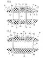
- eine Schnittdarstellung des Implantats gemäß
Figur 1 bei fixierten Knochenplatten, wobei ein Knoten in einer Ausnehmung versenkt ist; - Figur 3
- die gleiche Ansicht wie
Figur 2 , wobei der Knoten in einen Trennspalt zwischen fixierten Knochenplatten gebracht ist; - Figur 4
- eine Schnittansicht eines zweiten Ausführungsbeispiels;
- Figur 5
- eine Schnittansicht eines dritten Ausführungsbeispiels;
- Figur 6
- eine perspektivische Darstellung einer Variante eines Anlageelements und des Implantats gemäß
Figur 1 und - Figur 7
- eine schematische Darstellung eines Ausführungsbeispiels eines Implantats und eines Rutschknotenapplikators.
- FIG. 1
- a schematic perspective view of a first embodiment of an implant according to the invention;
- FIG. 2
- a sectional view of the implant according to
FIG. 1 in fixed bone plates, wherein a node is recessed in a recess; - FIG. 3
- the same view as
FIG. 2 wherein the node is placed in a separation gap between fixed bone plates; - FIG. 4
- a sectional view of a second embodiment;
- FIG. 5
- a sectional view of a third embodiment;
- FIG. 6
- a perspective view of a variant of a contact element and the implant according to
FIG. 1 and - FIG. 7
- a schematic representation of an embodiment of an implant and a slide node applicator.
Ein erstes Ausführungsbeispiels eines erfindungsgemäßen Implantats ist in den
Die Knochenplatten 12, 14 weisen jeweils eine Innenseite 16 und eine gegenüberliegende Außenseite 18 auf. Die Innenseite 16 weist dem Körperinneren zu; bei einer Schädelknochenplatte weist die Innenseite 16 dem Gehirn zu.The
Das Implantat 10 umfasst ein inneres Anlageelement 20 zur Anlage an die Innenseite 16 der Knochenplatten 12 und 14. Ferner umfasst das Implantat 10 ein äußeres Anlageelement 22 zur Anlage an die Außenseiten 18 der Knochenplatten 12 und 14.The
Bei dem gezeigten Ausführungsbeispiel haben das innere Anlageelement 20 und das äußere Anlageelement 22 einen kreisförmigen Querschnitt. Sie sind bezüglich ihrer Formgestaltung im Wesentlichen gleich ausgebildet.In the embodiment shown, the
Das innere Anlageelement 20 sowie das äußere Anlageelement 22 hat einen ringförmigen Anlagebereich, mit dem es an der Innenseite 16 der Knochenplatten 12, 14 anliegt. Dieser Anlagebereich 24 umfasst eine Grifffläche 26, welche "nicht-glatt" ausgebildet ist. Diese Grifffläche 26 dient dazu, den Angriff des inneren Anlageelements 20 an der Innenseite 16 der Knochenplatten 12, 14 bzw. des äußeren Anlageelements 22 an den Außenseiten 18 der Knochenplatten 12, 14 zu verbessern und insbesondere dazu, ein Abrutschen zu verhindern. Beispielsweise ist die Grifffläche 26 mittels einer umlaufenden Verzahnung, Riffelung oder Aufrauhung gebildet.The
Das innere Anlageelement 20 (und bei dem gezeigten Ausführungsbeispiel auch das äußeren Anlageelement 22) sind gewölbt ausgebildet, und zwar derart, dass zwischen dem Anlagebereich 24 und einem diesen insbesondere einstückig haltenden Bereich 28 ein Zwischenraum 30 ausgebildet ist.The inner contact element 20 (and in the embodiment shown, the outer contact element 22) are curved, in such a way that between the
Es kann vorgesehen sein, dass das innere Anlageelement 20 und/oder das äußere Anlageelement 22 bezogen auf eine Verbindungsrichtung 32 zwischen den beiden Anlageelementen 20 und 22 elastisch ausgebildet sind. Dies kann die Fixierung der Anlageelemente 20 und 22 aneinander und damit die Fixierung von zwischen den Anlageelementen 20 und 22 liegenden Knochenplatten 12 und 14 verbessern.It can be provided that the
Zur Verbindung des inneren Anlageelements 20 und des äußeren Anlageelements 22 ist (mindestens) ein linearflexibles Spannelement 34 vorgesehen. Bei dem Spannelement handelt es sich insbesondere um einen chirurgischen Faden oder um einen Draht. Das Spannelement dient dazu, die beiden Anlageelemente 20 und 22 so miteinander zu verbinden, dass diese nicht mehr voneinander entfernbar sind (und damit die Knochenplatten 12 und 14 relativ zueinander zu fixieren), wobei bei Zug am Spannelement 34 das innere Anlageelement 20 gegen das äußeren Anlageelement 22 verschiebbar ist.To connect the
Das Spannelement 34 ist insbesondere aus einem im Körper resorbierbaren Material hergestellt.The
Das Spannelement 34 durchsetzt zur Fixierung der Knochenplatten 12, 14 einen Trennspalt 36 zwischen den benachbarten Knochenplatten.The clamping
Es kann dabei vorgesehen sein, dass das innere Anlageelement 20 und/oder das äußere Anlageelement 22 mindestens einen Abstandshalter 38a, 38b aufweist (
Der oder die Abstandshalter 38a, 38b liegen insbesondere auf einer Linie mit unten noch näher beschriebenen Durchführungsausnehmungen für das Spannelement 34.The spacer or
Der bzw. die Abstandshalter 38a, 38b sind insbesondere einstückig an dem zugeordneten Anlageelement 20, 22 ausgebildet.The spacer or
Das innere Anlageelement 20 des Implantats 10 weist ein erstes Paar 44 beabstandeter benachbarter Durchführungsausnehmungen 46a, 46b auf und weist ein zweites Paar 48 beabstandeter benachbarter Durchführungsausnehmungen 50a, 50b auf. Die Durchführungsausnehmungen 46b und 50a sind innenliegende Durchführungsausnehmungen und die Durchführungsausnehmungen 46a, 50b sind außenliegende Durchführungsausnehmungen. Die Durchführungsausnehmung 46b ist benachbart zu der Durchführungsausnehmung 50a. Die Durchführungsausnehmungen 46a und 50b weisen zueinander den größten Abstand zwischen Durchführungsausnehmungen auf. Zwischen den Durchführungsausnehmungen 46a und 50b liegen die Durchführungsausnehmungen 46b und 50a.The
Die Durchführungsausnehmungen 46a, 46b, 50a und 50b sind insbesondere auf einer Linie (gemeinsam mit dem oder den Abstandshaltern 38a, 38b) angeordnet, so dass Spannelementbereiche des Spannelements 34, welche zwischen dem inneren Anlageelement 20 und dem äußeren Anlageelement 22 in dem Trennspalt 36 liegen, parallel ausgerichtet zueinander und fluchtend zueinander ausgerichtet positionierbar sind.The feedthrough recesses 46a, 46b, 50a and 50b are in particular arranged in a line (together with the spacer or
Das äußere Anlageelement 22 weist ein erstes Paar 52 von beabstandeten benachbarten Durchführungsausnehmungen 54a, 54b auf. Ferner weist das äußere Anlageelement 22 ein zweites Paar 56 von beabstandeten Durchführungsausnehmungen 58a, 58b auf. Das erste Paar 52 der Durchführungsausnehmungen 54a und 54b liegt dabei zwischen den Durchführungsausnehmungen 58a und 58b. Die Durchführungsausnehmungen 58a, 58b des zweiten Paars 56 sind außenliegenden Durchführungsausnehmungen; die Durchführungsausnehmungen 54a, 54b des ersten Paars 52 sind innenliegende Durchführungsausnehmungen. Die Durchführungsausnehmungen 54a und 58a sind benachbart und die Durchführungsausnehmungen 54b und 58b sind benachbart. Die Durchführungsausnehmungen 58a und 58b des zweiten Paars 56 weisen zueinander den maximalen Abstand zwischen Durchführungsausnehmungen am äußeren Anlageelement 22 auf.The
Die Durchführungsausnehmungen 54a, 54b, 58a und 58b des äußeren Anlageelements 22 sind angepasst an die Anordnung der Durchführungsausnehmungen 46a, 46b, 50a, 50b des inneren Anlageelements 20 ausgebildet. Insbesondere weisen benachbarte Durchführungsausnehmungen (58a und 54a; 54a und 54b; 54b und 58b) am äußeren Anlageelement 22 den gleichen Abstand auf wie entsprechende Durchführungsausnehmungen (46a und 46b; 46b und 50a; 50a und 50b) am inneren Anlageelement 20. Weiterhin liegen die Durchführungsausnehmungen 54a, 54b, 58a, 58b des äußeren Anlageelements 22 bevorzugt auf einer Linie.The feedthrough recesses 54a, 54b, 58a and 58b of the
Durch die angepasste Ausbildung der Durchführungsausnehmungen des inneren Anlageelements 20 und des äußeren Anlageelements 22 lässt sich eine parallele und fluchtende Führung des Spannelements 34 zwischen den Anlageelementen 20 und 22 erreichen.Due to the adapted design of the feed-through recesses of the
Das Spannelement 34 ist bei dem in den
Von der Durchführungsausnehmung 54a ist das Spannelement 34 zu der benachbarten Durchführungsausnehmung 54b geführt und durch diese hindurchgeführt. Zwischen den Durchführungsausnehmungen 54a, 54b liegt das Spannelement 34 in einem dritten Anlegebereich 62 an einer äußeren Oberfläche des äußeren Anlageelements 22 an, welche dem inneren Anlageelement 20 abgewandt ist.Of the
Das Spannelement 34 ist durch die Durchführungsausnehmung 54b bis zur Durchführungsausnehmung 50a geführt und durch diese hindurchgeführt. Von der Durchführungsausnehmung 50a ist das Spannelement 34 zur Durchführungsausnehmung 50b geführt und durch diese hindurchgeführt. Zwischen der Durchführungsausnehmung 50a und 50b liegt das Spannelement in einem zweiten Anlegebereich 64 an der äußeren Oberfläche des inneren Anlageelements 20 an.The clamping
Von der Durchführungsausnehmung 50b ist das Spannelement 34 zu der Durchführungsausnehmung 58b geführt und durch diese hindurchgeführt.Of the
Ausgehend von den Durchführungsausnehmungen 58a und 58b hat das Spannelement 34 freie Stränge, nämlich einen ersten freien Strang 66a (ausgehend von der Durchführungsausnehmung 58a) und einem freien Strang 66b (ausgehend von der Durchführungsausnehmung 58b).Starting from the feed-through
Wenn über das Implantat 10 die benachbarten Knochenplatten 12 und 14 miteinander fixiert sind, dann liegen die Bereiche des Spannelements 34, welche zwischen den Durchführungsausnehmungen 58a und 46a, 46b und 54a, 54b und 50a sowie 50b und 58b geführt sind, zum größten Teil im Trennspalt 36. Das Spannelement 34 ist über das erste Paar 44 von Durchführungsausnehmungen 46a, 46b am inneren Anlageelement 20 in einer ersten Schlaufe oder Kehre geführt, und das Spannelement 34 von dem inneren Anlageelement 20 ausgehend zu dem äußeren Anlageelement 22 umzulenken.When the neighboring
Durch das erste Paar 52 der Durchführungsausnehmungen 54a, 54b ist das Spannelement 34 in einer zweiten Schlaufe oder Kehre geführt, um das Spannelement 34 vom äußeren Anlageelement 22 zum inneren Anlageelement 20 umzulenken.By the
Durch das zweite Paar 48 der Durchführungsausnehmungen 50a, 50b am inneren Anlageelement 20 ist das Spannelement 34 in einer dritten Schlaufe oder Kehre geführt, um das Spannelement 34 wiederum vom inneren Anlageelement 20 zum äußeren Anlageelement 22 hin umzulenken.By the
Die freien Stränge 66a, 66b sind dann über das zweite Paar 56 der Durchführungsausnehmungen 58a, 58b am äußeren Anlageelement 22 aus diesem herausgeführt.The
Durch diese Führung des Spannelements 34 an den Anlageelementen 20 und 22 und zwischen den Anlageelementen 20 und 22 ist ein Flaschenzugsystem ausgebildet; wenn beispielsweise an den freien Strängen 66a, 66b gezogen wird (beispielsweise in der Richtung 32), dann wird dadurch das innere Anlageelement 20 in Richtung des äußeren Anlageelements 22 verschoben. Dadurch lässt sich eine Klemmkraft auf zwischen den Anlageelementen 20, 22 liegenden Knochenplatten 12, 14 ausüben, um diese miteinander zu fixieren.By this guidance of the clamping
Zur Feststellung dieser Verklemmung derart, dass die Knochenplatten 12, 14 nicht mehr voneinander entfernbar sind, das heißt das innere Anlageelement 20 und das äußere Anlageelement 22 nicht mehr voneinander entfernbar sind, ist eine Verbindung der freien Stränge 66a, 66b des Spannelements 34 vorgesehen. Diese Verbindung erfolgt in einem Verbindungsbereich 68, welcher insbesondere mittels eines Knotens 70 gebildet ist.To detect this jamming such that the
Der Knoten 70 ist vorzugsweise als Rutschknoten ausgebildet, welcher beispielsweise über einen Rutschknotenapplikator (
Ein Beispiel eines verwendbaren Rutschknotens ist ein Röder Knoten.An example of a usable slip knot is a Röder knot.
Es ist vorzugsweise vorgesehen, dass bei dem Implantat 10 der Knoten 70 und insbesondere Rutschknoten vorgefertigt ist, das heißt das Implantat 10 mit dem inneren Anlageelement 20, dem äußeren Anlageelement 22 und dem wie oben beschrieben geführten Spannelement 34 ausgeführt ist. Ferner sind die freien Stränge 66a, 66b bereits über einen Rutschknoten miteinander verbunden.It is preferably provided that in the
Über den Rutschknotenapplikator lässt sich der (Rutsch) Knoten 70 auf das äußere Anlageelement 22 zu verschieben und durch Festziehen beispielsweise über ein freies Ende des Spannelements 34 lassen sich die beiden Anlageelemente 20 und 22 relativ zueinander fixieren.Via the slip knot applicator, the (slide)
Wenn das innere Anlageelement 20 und/oder das äußere Anlageelement 22 elastisch ausgebildet sind, dann kann bei der Fixierung eine Kraft ausgeübt werden, welche den Abstand zwischen äußeren Oberflächen des inneren Anlageelements 20 und des äußeren Anlageelements 22 aufgrund elastischer Verformung verringert. Wenn diese Kraft weggenommen ist, dann vergrößert sich dieser Abstand leicht. Es lässt sich dadurch eine Art von Vorspannung ausüben.If the
Das äußere Anlageelement 22 weist eine Ausnehmung 74 auf, welche zum Aufnehmen bzw. Durchschieben des Verbindungsbereiches 68 des Spannelements 34, das heißt zur Aufnahme bzw. zum Durchschieben des Knotens 70 dient. Die Ausnehmung 74 ist so ausgebildet, dass der Verbindungsbereich 68 mindestens teilweise unterhalb einer äußeren Oberfläche des äußeren Anlageelements 22 positionierbar ist. Dadurch ragt der Verbindungsbereich 68 (insbesondere der Knoten 70) nicht oder nur wenig über diese Oberfläche hinaus. Es lassen sich dann Irritationen des umliegendes Gewebes aufgrund eines auf dem Implantat 10 liegenden Knotens 70 vermeiden, da der Knoten 70 durch die Ausnehmung 74 "versenkbar" ist. Weiterhin ist die Gefahr vermieden, dass der Knoten 70 (als Verbindungsbereich 68) für einen Patienten nach einer bestimmten Zeit fühlbar wird.The
Die Ausnehmung 74 ist vorzugsweise an einem äußeren Bereich des äußeren Anlageelements 22 angeordnet, in dem das äußere Anlageelement 22 verstärkt ausgebildet ist. Dadurch ist gewährleistet, dass die Ausnehmung 74 nicht die mechanische Stabilität des äußeren Anlageelements 22 beeinträchtigt.The
Vorzugsweise liegt die Ausnehmung 74 an der Durchführungsausnehmung 58b bzw. bildet diese. Die Ausnehmung 74 kann dann direkt als Durchführungsausnehmung genutzt werden. Dadurch verringert sich der Herstellungsaufwand. Weiterhin ist die mechanische Stabilität gewährleistet.Preferably, the
Es ist möglich, dass das äußere Anlageelement 22 auch eine Mehrzahl von solchen Ausnehmungen 74 aufweist. Dies kann beispielsweise notwendig sein, wenn zwei getrennte Spannelemente zur Verbindung der beiden Anlageelemente vorgesehen sind.It is possible that the
Grundsätzlich ist es auch möglich, dass das innere Anlageelement 20 mit einer solchen Ausnehmung 74 oder mehreren Ausnehmungen versehen ist. Es kann vorgesehen sein, dass das innere Anlageelement 20 und das äußere Anlageelement 22 identisch ausgebildet sind. Am inneren Anlageelement 20 hat eine Ausnehmung 74 keine Funktion, wobei sie jedoch auch nicht schädlich für die Fixierung der benachbarten Knochenplatten 12 und 14 ist. Wenn nur ein Typ von Anlageelement hergestellt werden muss, lassen sich die Herstellungskosten verringern und die Herstellung vereinfachen.In principle, it is also possible that the
Bei dem in den
In
Das Implantat 10 funktioniert wie folgt:
Die Anlageelemente 20 und 22 sind überdas Spannelement 34 "lose" miteinander verbunden, wobei vorzugsweiseein Rutschknoten 70 anden freien Strängen Das innere Anlageelement 20 wird, wenndie benachbarten Knochenplatten Knochenplatten
- The
contact elements tensioning element 34, wherein preferably aslip knot 70 is prefabricated on thefree strands adjacent bone plates inner abutment element 20 is placed under thebone plates inner abutment element 20.
Das Spannelement 34 verläuft dann in dem Trennspalt 36.The clamping
An den freien Strängen 66a, 66b wird gezogen, um den Abstand zwischen dem äußeren Anlageelement 22 und dem inneren Anlageelement 20 zu verringern. Dadurch lässt sich das innere Anlageelement 20 gegen die Innenseiten 16 der Knochenplatten 12, 14 drücken und das äußere Anlageelement 22 gegen die Außenseiten 18 der Knochenplatten 12 und 14.The
Zur Fixierung dieser Stellung wird der Rutschknoten 70 beispielsweise über einen Rutschknotenapplikator auf das äußere Anlageelement 22 zu geschoben und dabei in die Ausnehmung 74 verschoben. Von dort aus kann der Knoten 70 in den Trennspalt 36 verschoben werden, so dass er nicht über das äußere Anlageelement 22 hinausragt.To fix this position, the
Durch Ziehen an einem freien Ende des Spannelements 34 wird der Knoten 70 zugezogen.By pulling on a free end of the clamping
Überstehende Bereiche des Spannelements 34 können dann abgeschnitten werden.Overhanging portions of the
Bei einem zweiten Ausführungsbeispiel 81, welches in einer Schnittdarstellung schematisch in
Der Ausnehmung 82 und damit dem Aufnahmeraum 84 ist ein Boden 86 zugeordnet, welcher den Aufnahmeraum 84 zu der Unterseite 78 des äußeren Anlageelements 22 verschließt.The
In dem Boden 86 ist eine Durchführungsausnehmung 88 gebildet, durch die das Spannelement 34 geführt ist, durch die jedoch der Knoten 70 nicht durchtauchen kann. (Die Durchführungsausnehmung 88 entspricht der Durchführungsausnehmung 58b gemäß dem Ausführungsbeispiel der
Ansonsten funktioniert das Implantat 81 gemäß diesem Ausführungsbeispiel wie oben beschrieben.Otherwise, the
Bei einem dritten Ausführungsbeispiel eines Implantats, welches in einer schematischen Schnittdarstellung in
Das äußere Anlageelement 94 weist angepasst an die Anordnung der Durchführungsausnehmungen 96a, 96b im inneren Anlageelement 92 eine erste Durchführungsausnehmung 102a und eine zweite beabstandete benachbarte Durchführungsausnehmung 102b auf.The
Das Spannelement 98 ist von der Durchführungsausnehmung 102a von dem äußeren Anlageelement 94 zu der Durchführungsausnehmung 96a des inneren Anlageelements 92 geführt und durch diese Durchführungsausnehmung 96a durchgeführt. Es ist weiterhin zwischen den Durchführungsausnehmungen 96a und 96b in einer Schlaufe oder Kehre geführt und liegt in dem Anlegebereich 100 an dem inneren Anlageelement 92 an. Es wird an der Durchführungsausnehmung 96b, durch welche es geführt ist, umgelenkt in Richtung des äußeren Anlageelements 94. Dort ist es durch die Durchführungsausnehmung 102b geführt.The clamping
Freie Stränge 104a, 104b des Spannelements 98 sind aus den jeweiligen Durchführungsausnehmungen 102a und 102b herausgeführt. Sie sind über einen Verbindungsbereich 106 und insbesondere einen Knoten 108 miteinander verbunden, um die freien Stränge 104a, 104b miteinander zu verbinden und eine Fixierungsstellung der beiden Anlageelemente 92 und 94 zueinander zu sichern.
Zwischen den Durchführungsausnehmungen 102a und 102b ist an dem äußeren Anlageelement 94 eine insbesondere muldenförmige Ausnehmung 110 gebildet. In diese Ausnehmung 110 lässt sich der Knoten 108 einlegen, so dass er nicht oder höchstens teilweise über eine Oberseite 112 des äußeren Anlageelements 94 hinausragt.Between the feed-through
Ansonsten funktioniert das Implantat 90 so wie oben anhand der anderen Ausführungsbeispiele beschrieben.Otherwise, the
In
Das Implantat 124 ist grundsätzlich so ausgebildet, wie oben beschrieben.The
Beispielsweise sitzt die Applikatorspitze 118 an einem Schiebeglied 126 des Rutschknotenapplikators 114. Mit dem Schiebeglied 126 ist ein Griffelement 128 verbunden. Bei einem Ausführungsbeispiel ist die Verbindung derart, dass beim Überschreiten einer bestimmten Verschiebekraft die Verbindung zwischen dem Griffelement 128 und dem Schiebeglied 126 gelöst wird. Ein solcher Rutschknotenapplikator (Vorrichtung zum Zusammenschieben einer Schlaufe eines Fadens, die durch einen längs des Fadens verschiebbaren Rutschknoten des distalen freien Endes des Fadens gebildet wird) ist in der
Claims (15)
Translated fromGermandadurch gekennzeichnet , dass das äußere Anlageelement (22; 94) mindestens eine Ausnehmung (74; 82; 110) zur mindestens teilweisen Aufnahme eines Verbindungsbereiches (68; 106) zwischen freien Strängen (66a, 66b; 104a, 104b) des Spannelements (34; 98) oder zur Durchführung des Verbindungsbereichs (68) in einen Trennspalt (36) zwischen den benachbarten Knochenplatten (12, 14) aufweist, wobei die mindestens eine Ausnehmung (74; 82; 110) so ausgebildet ist, dass der Verbindungsbereich (68; 106) mindestens teilweise unterhalb einer äußeren Oberfläche des äußeren Anlageelements (22; 94) positionierbar ist.An implant for fixing adjacent bone plates (12, 14), in particular adjacent cranial bone plates, wherein the bone plates (12, 14) each have an inner side (16) and an outer side (18), comprising an inner abutment element (20; 92) for abutment with the Inner sides (16) of the adjacent bone plates (12, 14), an outer abutment element (22, 94) for engaging the outer sides (18) of the adjacent bone plates (12, 14) and a linearly flexible clamping element (34, 98) for connecting the inner Contact element (20; 92) and the outer abutment element (22; 94) such that they are no longer removable from each other,
characterized in that the outer contact element (22; 94) has at least one recess (74; 82; 110) for at least partially receiving a connecting region (68; 106) between free strands (66a, 66b; 104a, 104b) of the clamping element (34; 98) or for passing the connection region (68) into a separating gap (36) between the adjacent bone plates (12, 14), wherein the at least one recess (74; 82; 110) is formed such that the connection region (68; ) is at least partially positionable below an outer surface of the outer abutment member (22; 94).
Applications Claiming Priority (2)
| Application Number | Priority Date | Filing Date | Title |
|---|---|---|---|
| DE102004038823ADE102004038823B3 (en) | 2004-08-04 | 2004-08-04 | Implant for fixing adjacent bone plates |
| EP05754309AEP1773221B1 (en) | 2004-08-04 | 2005-05-27 | Implant for securing neighbouring bone plates |
Related Parent Applications (1)
| Application Number | Title | Priority Date | Filing Date |
|---|---|---|---|
| EP05754309.2Division | 2005-05-27 |
Publications (2)
| Publication Number | Publication Date |
|---|---|
| EP2361569A1true EP2361569A1 (en) | 2011-08-31 |
| EP2361569B1 EP2361569B1 (en) | 2013-07-31 |
Family
ID=34970863
Family Applications (2)
| Application Number | Title | Priority Date | Filing Date |
|---|---|---|---|
| EP05754309AExpired - LifetimeEP1773221B1 (en) | 2004-08-04 | 2005-05-27 | Implant for securing neighbouring bone plates |
| EP11166542.8AExpired - LifetimeEP2361569B1 (en) | 2004-08-04 | 2005-05-27 | Implant for securing neighbouring bone plates |
Family Applications Before (1)
| Application Number | Title | Priority Date | Filing Date |
|---|---|---|---|
| EP05754309AExpired - LifetimeEP1773221B1 (en) | 2004-08-04 | 2005-05-27 | Implant for securing neighbouring bone plates |
Country Status (7)
| Country | Link |
|---|---|
| US (2) | US8403929B2 (en) |
| EP (2) | EP1773221B1 (en) |
| JP (1) | JP5080253B2 (en) |
| KR (1) | KR100928957B1 (en) |
| DE (1) | DE102004038823B3 (en) |
| ES (2) | ES2428517T3 (en) |
| WO (1) | WO2006015635A1 (en) |
Cited By (1)
| Publication number | Priority date | Publication date | Assignee | Title |
|---|---|---|---|---|
| EP3388008A4 (en)* | 2016-10-13 | 2019-03-13 | Suzhou Ship Biological Technology Co., Ltd. | Absorbable skull fixation lock system and method for using same |
Families Citing this family (92)
| Publication number | Priority date | Publication date | Assignee | Title |
|---|---|---|---|---|
| US8758400B2 (en) | 2000-01-05 | 2014-06-24 | Integrated Vascular Systems, Inc. | Closure system and methods of use |
| DE60144328D1 (en) | 2000-09-08 | 2011-05-12 | Abbott Vascular Inc | Surgical clamp |
| US6623510B2 (en) | 2000-12-07 | 2003-09-23 | Integrated Vascular Systems, Inc. | Closure device and methods for making and using them |
| US6695867B2 (en) | 2002-02-21 | 2004-02-24 | Integrated Vascular Systems, Inc. | Plunger apparatus and methods for delivering a closure device |
| US8690910B2 (en) | 2000-12-07 | 2014-04-08 | Integrated Vascular Systems, Inc. | Closure device and methods for making and using them |
| IES20030424A2 (en) | 2002-06-04 | 2003-12-10 | Robert Stevenson | Blood vessel closure clip and delivery device |
| US8398656B2 (en) | 2003-01-30 | 2013-03-19 | Integrated Vascular Systems, Inc. | Clip applier and methods of use |
| US8202293B2 (en) | 2003-01-30 | 2012-06-19 | Integrated Vascular Systems, Inc. | Clip applier and methods of use |
| DE10326690B4 (en)* | 2003-06-04 | 2005-04-28 | Aesculap Ag & Co Kg | Sternum closure |
| US7749250B2 (en) | 2006-02-03 | 2010-07-06 | Biomet Sports Medicine, Llc | Soft tissue repair assembly and associated method |
| US9801708B2 (en) | 2004-11-05 | 2017-10-31 | Biomet Sports Medicine, Llc | Method and apparatus for coupling soft tissue to a bone |
| US7658751B2 (en) | 2006-09-29 | 2010-02-09 | Biomet Sports Medicine, Llc | Method for implanting soft tissue |
| US7905904B2 (en) | 2006-02-03 | 2011-03-15 | Biomet Sports Medicine, Llc | Soft tissue repair device and associated methods |
| US8361113B2 (en) | 2006-02-03 | 2013-01-29 | Biomet Sports Medicine, Llc | Method and apparatus for coupling soft tissue to a bone |
| US8298262B2 (en) | 2006-02-03 | 2012-10-30 | Biomet Sports Medicine, Llc | Method for tissue fixation |
| US8128658B2 (en) | 2004-11-05 | 2012-03-06 | Biomet Sports Medicine, Llc | Method and apparatus for coupling soft tissue to bone |
| US9017381B2 (en) | 2007-04-10 | 2015-04-28 | Biomet Sports Medicine, Llc | Adjustable knotless loops |
| US8303604B2 (en) | 2004-11-05 | 2012-11-06 | Biomet Sports Medicine, Llc | Soft tissue repair device and method |
| US7909851B2 (en) | 2006-02-03 | 2011-03-22 | Biomet Sports Medicine, Llc | Soft tissue repair device and associated methods |
| US8137382B2 (en) | 2004-11-05 | 2012-03-20 | Biomet Sports Medicine, Llc | Method and apparatus for coupling anatomical features |
| US8118836B2 (en) | 2004-11-05 | 2012-02-21 | Biomet Sports Medicine, Llc | Method and apparatus for coupling soft tissue to a bone |
| US8840645B2 (en) | 2004-11-05 | 2014-09-23 | Biomet Sports Medicine, Llc | Method and apparatus for coupling soft tissue to a bone |
| US8088130B2 (en) | 2006-02-03 | 2012-01-03 | Biomet Sports Medicine, Llc | Method and apparatus for coupling soft tissue to a bone |
| US8998949B2 (en) | 2004-11-09 | 2015-04-07 | Biomet Sports Medicine, Llc | Soft tissue conduit device |
| US8313497B2 (en) | 2005-07-01 | 2012-11-20 | Abbott Laboratories | Clip applier and methods of use |
| US11259792B2 (en) | 2006-02-03 | 2022-03-01 | Biomet Sports Medicine, Llc | Method and apparatus for coupling anatomical features |
| US8506597B2 (en) | 2011-10-25 | 2013-08-13 | Biomet Sports Medicine, Llc | Method and apparatus for interosseous membrane reconstruction |
| US8652172B2 (en) | 2006-02-03 | 2014-02-18 | Biomet Sports Medicine, Llc | Flexible anchors for tissue fixation |
| US11311287B2 (en) | 2006-02-03 | 2022-04-26 | Biomet Sports Medicine, Llc | Method for tissue fixation |
| US9538998B2 (en) | 2006-02-03 | 2017-01-10 | Biomet Sports Medicine, Llc | Method and apparatus for fracture fixation |
| US8968364B2 (en) | 2006-02-03 | 2015-03-03 | Biomet Sports Medicine, Llc | Method and apparatus for fixation of an ACL graft |
| US8801783B2 (en) | 2006-09-29 | 2014-08-12 | Biomet Sports Medicine, Llc | Prosthetic ligament system for knee joint |
| US9271713B2 (en) | 2006-02-03 | 2016-03-01 | Biomet Sports Medicine, Llc | Method and apparatus for tensioning a suture |
| US10517587B2 (en) | 2006-02-03 | 2019-12-31 | Biomet Sports Medicine, Llc | Method and apparatus for forming a self-locking adjustable loop |
| US8597327B2 (en) | 2006-02-03 | 2013-12-03 | Biomet Manufacturing, Llc | Method and apparatus for sternal closure |
| US8574235B2 (en) | 2006-02-03 | 2013-11-05 | Biomet Sports Medicine, Llc | Method for trochanteric reattachment |
| US9408599B2 (en) | 2006-02-03 | 2016-08-09 | Biomet Sports Medicine, Llc | Method and apparatus for coupling soft tissue to a bone |
| US8652171B2 (en) | 2006-02-03 | 2014-02-18 | Biomet Sports Medicine, Llc | Method and apparatus for soft tissue fixation |
| US8562645B2 (en) | 2006-09-29 | 2013-10-22 | Biomet Sports Medicine, Llc | Method and apparatus for forming a self-locking adjustable loop |
| US8562647B2 (en) | 2006-09-29 | 2013-10-22 | Biomet Sports Medicine, Llc | Method and apparatus for securing soft tissue to bone |
| US9149267B2 (en) | 2006-02-03 | 2015-10-06 | Biomet Sports Medicine, Llc | Method and apparatus for coupling soft tissue to a bone |
| US8771352B2 (en) | 2011-05-17 | 2014-07-08 | Biomet Sports Medicine, Llc | Method and apparatus for tibial fixation of an ACL graft |
| US9468433B2 (en) | 2006-02-03 | 2016-10-18 | Biomet Sports Medicine, Llc | Method and apparatus for forming a self-locking adjustable loop |
| US9078644B2 (en) | 2006-09-29 | 2015-07-14 | Biomet Sports Medicine, Llc | Fracture fixation device |
| DE102006021025B3 (en)* | 2006-04-28 | 2008-01-03 | Aesculap Ag & Co. Kg | Surgical fixation device for two bone parts |
| US8556930B2 (en) | 2006-06-28 | 2013-10-15 | Abbott Laboratories | Vessel closure device |
| DE102006046424B3 (en) | 2006-09-22 | 2007-11-08 | Aesculap Ag & Co. Kg | Sternum closure comprises pairs of plates with L-shaped cross-section positioned on inner surface of sternum and plates with C-shaped cross-section on its outer surface, plates being fastened together by pins passing through them |
| DE102006046428A1 (en) | 2006-09-22 | 2008-04-03 | Aesculap Ag & Co. Kg | sternal closure |
| US8672969B2 (en)* | 2006-09-29 | 2014-03-18 | Biomet Sports Medicine, Llc | Fracture fixation device |
| US11259794B2 (en) | 2006-09-29 | 2022-03-01 | Biomet Sports Medicine, Llc | Method for implanting soft tissue |
| US9918826B2 (en) | 2006-09-29 | 2018-03-20 | Biomet Sports Medicine, Llc | Scaffold for spring ligament repair |
| US8500818B2 (en) | 2006-09-29 | 2013-08-06 | Biomet Manufacturing, Llc | Knee prosthesis assembly with ligament link |
| US9282965B2 (en) | 2008-05-16 | 2016-03-15 | Abbott Laboratories | Apparatus and methods for engaging tissue |
| US8282674B2 (en)* | 2008-07-18 | 2012-10-09 | Suspension Orthopaedic Solutions, Inc. | Clavicle fixation |
| US9271706B2 (en)* | 2008-08-12 | 2016-03-01 | Covidien Lp | Medical device for wound closure and method of use |
| US12245759B2 (en) | 2008-08-22 | 2025-03-11 | Biomet Sports Medicine, Llc | Method and apparatus for coupling soft tissue to bone |
| US12419632B2 (en) | 2008-08-22 | 2025-09-23 | Biomet Sports Medicine, Llc | Method and apparatus for coupling anatomical features |
| US9486191B2 (en) | 2009-01-09 | 2016-11-08 | Abbott Vascular, Inc. | Closure devices |
| US9414820B2 (en) | 2009-01-09 | 2016-08-16 | Abbott Vascular Inc. | Closure devices, systems, and methods |
| US20100179589A1 (en) | 2009-01-09 | 2010-07-15 | Abbott Vascular Inc. | Rapidly eroding anchor |
| US20100185234A1 (en)* | 2009-01-16 | 2010-07-22 | Abbott Vascular Inc. | Closure devices, systems, and methods |
| US8343227B2 (en) | 2009-05-28 | 2013-01-01 | Biomet Manufacturing Corp. | Knee prosthesis assembly with ligament link |
| US12096928B2 (en) | 2009-05-29 | 2024-09-24 | Biomet Sports Medicine, Llc | Method and apparatus for coupling soft tissue to a bone |
| US20110054492A1 (en) | 2009-08-26 | 2011-03-03 | Abbott Laboratories | Medical device for repairing a fistula |
| US8740949B2 (en) | 2011-02-24 | 2014-06-03 | Spinal Elements, Inc. | Methods and apparatus for stabilizing bone |
| US12329373B2 (en) | 2011-05-02 | 2025-06-17 | Biomet Sports Medicine, Llc | Method and apparatus for soft tissue fixation |
| US9357991B2 (en) | 2011-11-03 | 2016-06-07 | Biomet Sports Medicine, Llc | Method and apparatus for stitching tendons |
| US9314241B2 (en) | 2011-11-10 | 2016-04-19 | Biomet Sports Medicine, Llc | Apparatus for coupling soft tissue to a bone |
| US9381013B2 (en) | 2011-11-10 | 2016-07-05 | Biomet Sports Medicine, Llc | Method for coupling soft tissue to a bone |
| US9370350B2 (en) | 2011-11-10 | 2016-06-21 | Biomet Sports Medicine, Llc | Apparatus for coupling soft tissue to a bone |
| US9332976B2 (en) | 2011-11-30 | 2016-05-10 | Abbott Cardiovascular Systems, Inc. | Tissue closure device |
| US9433438B2 (en) | 2012-11-15 | 2016-09-06 | DePuy Synthes Products, Inc. | Locking member for a bone fixation device |
| US9364209B2 (en) | 2012-12-21 | 2016-06-14 | Abbott Cardiovascular Systems, Inc. | Articulating suturing device |
| US9795426B2 (en)* | 2013-03-07 | 2017-10-24 | DePuy Synthes Products, Inc. | Implants |
| US9757119B2 (en) | 2013-03-08 | 2017-09-12 | Biomet Sports Medicine, Llc | Visual aid for identifying suture limbs arthroscopically |
| US9918827B2 (en) | 2013-03-14 | 2018-03-20 | Biomet Sports Medicine, Llc | Scaffold for spring ligament repair |
| US9839450B2 (en) | 2013-09-27 | 2017-12-12 | Spinal Elements, Inc. | Device and method for reinforcement of a facet |
| CN103479421A (en)* | 2013-10-05 | 2014-01-01 | 王学建 | Defect reconstruction instrument for endoscopic endonasal operation of neurosurgery development |
| US10136886B2 (en) | 2013-12-20 | 2018-11-27 | Biomet Sports Medicine, Llc | Knotless soft tissue devices and techniques |
| US9615822B2 (en) | 2014-05-30 | 2017-04-11 | Biomet Sports Medicine, Llc | Insertion tools and method for soft anchor |
| US9700291B2 (en) | 2014-06-03 | 2017-07-11 | Biomet Sports Medicine, Llc | Capsule retractor |
| US10039543B2 (en) | 2014-08-22 | 2018-08-07 | Biomet Sports Medicine, Llc | Non-sliding soft anchor |
| US11478275B2 (en) | 2014-09-17 | 2022-10-25 | Spinal Elements, Inc. | Flexible fastening band connector |
| US9955980B2 (en) | 2015-02-24 | 2018-05-01 | Biomet Sports Medicine, Llc | Anatomic soft tissue repair |
| US9974534B2 (en) | 2015-03-31 | 2018-05-22 | Biomet Sports Medicine, Llc | Suture anchor with soft anchor of electrospun fibers |
| US10758224B2 (en) | 2017-03-27 | 2020-09-01 | Trimed, Incorporated | System and method controlling a relationship between first and second bodies on a person |
| CA3099263C (en)* | 2018-05-04 | 2022-05-10 | Paragon 28, Inc. | Soft tissue retention device, instrumentation and related methods |
| WO2021163313A1 (en) | 2020-02-14 | 2021-08-19 | Spinal Elements, Inc. | Bone tie methods |
| JP7736699B2 (en)* | 2020-04-30 | 2025-09-09 | アキュームド・エルエルシー | Friction-reduced knotless suture routing |
| US12369952B2 (en) | 2021-12-10 | 2025-07-29 | Spinal Elements, Inc. | Bone tie and portal |
| CN116370052B (en)* | 2023-06-07 | 2023-08-18 | 杭州锐健马斯汀医疗器材有限公司 | Titanium plate, titanium plate assembly and titanium plate implantation system |
| CN118319563B (en)* | 2024-06-14 | 2024-08-23 | 北京爱康宜诚医疗器材有限公司 | Self-locking type patch prosthesis |
Citations (4)
| Publication number | Priority date | Publication date | Assignee | Title |
|---|---|---|---|---|
| US5921986A (en) | 1998-02-06 | 1999-07-13 | Bonutti; Peter M. | Bone suture |
| DE19952359C1 (en) | 1999-10-30 | 2001-03-22 | Aesculap Ag & Co Kg | Surgical connection has coupling element, two placement elements, bone plates, and holders |
| DE10128917C1 (en) | 2001-06-15 | 2002-10-24 | Aesculap Ag & Co Kg | Surgical implant for fixing bone plates for repair of broken bone has two discs with crenellated edges, interengaging toothed projections and holes for fastening cord |
| DE10161724A1 (en) | 2001-12-15 | 2003-07-10 | Aesculap Ag & Co Kg | Surgical device for pushing a thread loop together |
Family Cites Families (49)
| Publication number | Priority date | Publication date | Assignee | Title |
|---|---|---|---|---|
| DE7802791U1 (en) | 1978-05-24 | Semm, Kurt, Prof. Dr.Med., 2300 Kiel | Device for tying off biological tissue | |
| US261501A (en) | 1882-07-18 | Bag and sail tie | ||
| US2576649A (en)* | 1949-03-12 | 1951-11-27 | Milo W Slind | Skull clamp |
| DE912619C (en) | 1952-03-22 | 1954-05-31 | Walter Hirsch | Device for producing and tightening a knot formed from loops of thread and comprising a body |
| US2856933A (en)* | 1958-01-27 | 1958-10-21 | Hildebrand Herbert | Surgical snare |
| NL133643C (en)* | 1967-01-10 | 1900-01-01 | ||
| DE2125556B1 (en) | 1971-05-22 | 1972-07-06 | Fischer, Artur, 7241 Tumlingen | Connector for kneecap fractures |
| US3910281A (en)* | 1973-10-09 | 1975-10-07 | Bio Medicus Inc | Suture anchor |
| US4177813A (en)* | 1978-01-09 | 1979-12-11 | Med General, Inc. | Vessel occluder |
| DE2804070A1 (en) | 1978-01-31 | 1979-08-02 | Kurt Prof Dr Med Semm | Biological tissue ligature forming instrument - has insertion sleeve accommodating sliding sleeve containing looped thread |
| US4754529A (en)* | 1980-07-14 | 1988-07-05 | Dennison Manufacturing Company | Bundling of objects |
| US5258011A (en)* | 1987-01-12 | 1993-11-02 | Drews Robert C | Corneal rivet |
| DE3709067A1 (en) | 1987-03-19 | 1988-09-29 | Ewald Hensler | Medical, especially surgical, instrument |
| US4802477A (en)* | 1987-05-07 | 1989-02-07 | Shlomo Gabbay | Sternum closure device |
| US4765329A (en)* | 1987-10-19 | 1988-08-23 | Cumming, Redwitz & Wilson, Inc. | Intraocular lens insertion instrument |
| US4966600A (en)* | 1989-01-26 | 1990-10-30 | Songer Robert J | Surgical securance method |
| DE8910462U1 (en) | 1989-09-01 | 1990-01-04 | Hensler, Ewald, 7717 Immendingen | Medical, especially surgical instrument |
| US5021059A (en)* | 1990-05-07 | 1991-06-04 | Kensey Nash Corporation | Plug device with pulley for sealing punctures in tissue and methods of use |
| EP0520177B1 (en)* | 1991-05-24 | 1995-12-13 | Synthes AG, Chur | Resorbable tendon and bone augmentation device |
| CA2078530A1 (en)* | 1991-09-23 | 1993-03-24 | Jay Erlebacher | Percutaneous arterial puncture seal device and insertion tool therefore |
| US5250049A (en)* | 1992-01-10 | 1993-10-05 | Michael Roger H | Bone and tissue connectors |
| JPH0613038B2 (en) | 1992-02-10 | 1994-02-23 | 島 由美子 | Skull bone valve fixation device |
| US5242459A (en)* | 1992-07-10 | 1993-09-07 | Laparomed Corporation | Device and method for applying a ligating loop |
| US5330491A (en) | 1992-09-18 | 1994-07-19 | Ethicon, Inc. | Endoscopic suturing device |
| DE4243427C1 (en)* | 1992-12-15 | 1994-03-10 | Ethicon Gmbh | System for applying knots in surgical sutures |
| FR2704132B1 (en)* | 1993-04-23 | 1995-07-13 | Ethnor | System for ligature and / or suture for endoscopic surgery. |
| US5423858A (en)* | 1993-09-30 | 1995-06-13 | United States Surgical Corporation | Septoplasty fasteners and device for applying same |
| US5569250A (en)* | 1994-03-01 | 1996-10-29 | Sarver; David R. | Method and apparatus for securing adjacent bone portions |
| US5433727A (en)* | 1994-08-16 | 1995-07-18 | Sideris; Eleftherios B. | Centering buttoned device for the occlusion of large defects for occluding |
| US5549620A (en)* | 1994-12-06 | 1996-08-27 | Bremer; Paul | Brain surgery with craniotomy pin |
| DE19603887C2 (en)* | 1996-02-03 | 1998-07-02 | Lerch Karl Dieter | Arrangement for fixing a piece of bone that has been removed from the skull capsule for the purpose of the surgical intervention to the remaining skull leg |
| US5707373A (en)* | 1996-04-26 | 1998-01-13 | Ikonos Corporation | Bone fastener and instrument for insertion thereof |
| DE29724567U1 (en)* | 1996-02-14 | 2003-01-16 | Walter Lorenz Surgical, Inc., Jacksonville, Fla. | Bone fixation device and instrument for inserting the bone fixation device |
| DE29614921U1 (en) | 1996-08-28 | 1996-10-17 | Aesculap Ag, 78532 Tuttlingen | Surgical connecting element for fixing a segment of the calotte |
| DE19636976C2 (en)* | 1996-09-12 | 2003-05-15 | Wolf Gmbh Richard | Endoscopic instrument with an operating rod |
| DE19731453C2 (en)* | 1997-07-22 | 1999-07-22 | Storz Karl Gmbh & Co | Device for limiting the transmission of force on surgical instruments |
| US6063106A (en)* | 1997-09-19 | 2000-05-16 | Gibson; William Frits Stewart | Surgical spacer |
| DE19832797C1 (en) | 1998-07-21 | 2000-02-24 | Aesculap Ag & Co Kg | Fixture device for adjacent bone plates, comprises first plate-shaped locating component with centrally vertically extending shaft and second plate-shaped locating component with central aperture |
| US6022351A (en)* | 1999-02-23 | 2000-02-08 | Bremer; Paul W. | Skull closure device and procedure |
| US6379363B1 (en)* | 1999-09-24 | 2002-04-30 | Walter Lorenz Surgical, Inc. | Method and apparatus for reattachment of a cranial flap using a cranial clamp |
| DE29919090U1 (en) | 1999-10-30 | 2000-01-13 | Aesculap AG & Co. KG, 78532 Tuttlingen | Surgical connecting element for fixing adjacent bone plates |
| US7153312B1 (en)* | 1999-12-02 | 2006-12-26 | Smith & Nephew Inc. | Closure device and method for tissue repair |
| US6514274B1 (en)* | 2000-02-25 | 2003-02-04 | Arthrotek, Inc. | Method and apparatus for rotator cuff repair |
| AU2001296265A1 (en)* | 2000-09-15 | 2002-03-26 | Macropore, Inc. | Cranial flap fixation device |
| US7670361B2 (en)* | 2001-06-15 | 2010-03-02 | Aesculap Ag | Implant for fixing bone plates |
| US6685707B2 (en)* | 2001-09-25 | 2004-02-03 | Walter Lorenz Surgical, Inc. | Cranial clamp and method for fixating a bone plate |
| US7048737B2 (en)* | 2002-06-11 | 2006-05-23 | Bioplate, Inc. | Cranial bone flap fixation system and method |
| US7387633B2 (en)* | 2003-04-04 | 2008-06-17 | Osteomed L.P. | Cranial flap fixation system and method |
| US7455683B2 (en)* | 2004-02-26 | 2008-11-25 | Depuy Mitek, Inc. | Methods and devices for repairing triangular fibrocartilage complex tears |
- 2004
- 2004-08-04DEDE102004038823Apatent/DE102004038823B3/ennot_activeExpired - Fee Related
- 2005
- 2005-05-27ESES11166542Tpatent/ES2428517T3/ennot_activeExpired - Lifetime
- 2005-05-27EPEP05754309Apatent/EP1773221B1/ennot_activeExpired - Lifetime
- 2005-05-27KRKR1020077002726Apatent/KR100928957B1/ennot_activeExpired - Lifetime
- 2005-05-27EPEP11166542.8Apatent/EP2361569B1/ennot_activeExpired - Lifetime
- 2005-05-27JPJP2007524186Apatent/JP5080253B2/ennot_activeExpired - Lifetime
- 2005-05-27ESES05754309Tpatent/ES2401337T3/ennot_activeExpired - Lifetime
- 2005-05-27WOPCT/EP2005/005738patent/WO2006015635A1/enactiveApplication Filing
- 2007
- 2007-02-05USUS11/702,258patent/US8403929B2/enactiveActive
- 2013
- 2013-02-25USUS13/775,818patent/US8986352B2/ennot_activeExpired - Lifetime
Patent Citations (4)
| Publication number | Priority date | Publication date | Assignee | Title |
|---|---|---|---|---|
| US5921986A (en) | 1998-02-06 | 1999-07-13 | Bonutti; Peter M. | Bone suture |
| DE19952359C1 (en) | 1999-10-30 | 2001-03-22 | Aesculap Ag & Co Kg | Surgical connection has coupling element, two placement elements, bone plates, and holders |
| DE10128917C1 (en) | 2001-06-15 | 2002-10-24 | Aesculap Ag & Co Kg | Surgical implant for fixing bone plates for repair of broken bone has two discs with crenellated edges, interengaging toothed projections and holes for fastening cord |
| DE10161724A1 (en) | 2001-12-15 | 2003-07-10 | Aesculap Ag & Co Kg | Surgical device for pushing a thread loop together |
Cited By (1)
| Publication number | Priority date | Publication date | Assignee | Title |
|---|---|---|---|---|
| EP3388008A4 (en)* | 2016-10-13 | 2019-03-13 | Suzhou Ship Biological Technology Co., Ltd. | Absorbable skull fixation lock system and method for using same |
Also Published As
| Publication number | Publication date |
|---|---|
| US20070250059A1 (en) | 2007-10-25 |
| EP2361569B1 (en) | 2013-07-31 |
| JP2008508067A (en) | 2008-03-21 |
| JP5080253B2 (en) | 2012-11-21 |
| WO2006015635A1 (en) | 2006-02-16 |
| US20130190763A1 (en) | 2013-07-25 |
| EP1773221A1 (en) | 2007-04-18 |
| KR20070058444A (en) | 2007-06-08 |
| DE102004038823B3 (en) | 2006-03-30 |
| ES2401337T3 (en) | 2013-04-18 |
| EP1773221B1 (en) | 2013-01-30 |
| ES2428517T3 (en) | 2013-11-08 |
| US8403929B2 (en) | 2013-03-26 |
| KR100928957B1 (en) | 2009-11-30 |
| US8986352B2 (en) | 2015-03-24 |
Similar Documents
| Publication | Publication Date | Title |
|---|---|---|
| EP2361569B1 (en) | Implant for securing neighbouring bone plates | |
| EP1223874B1 (en) | Surgical connecting element for fixing adjacent bone plates | |
| DE3879025T2 (en) | COMPRESSION BONE CLAMP. | |
| DE4102462C2 (en) | Stabilizing element for osteosynthesis of bone fragments, especially for the fixation of bone fractures | |
| DE69424197T2 (en) | Two-part surgical clip | |
| DE3855621T2 (en) | Surgical fastening device made of polymeric material | |
| EP1460951B1 (en) | Implant for fixing bone plates | |
| EP1631207B1 (en) | Sternum closure | |
| DE69705489T2 (en) | Surgical clip | |
| EP1613225B1 (en) | Bone fixation device | |
| EP0635246A1 (en) | Dowel for fusing vertebral bodies | |
| DE4021246A1 (en) | Holding fractured bone in place - involves use of pipe clip with tensioning screw | |
| EP1395187B1 (en) | Implant for fixing adjacent osseous plates | |
| DE29919090U1 (en) | Surgical connecting element for fixing adjacent bone plates | |
| EP0876798A2 (en) | Strapping apparatus for fixing bone fractures | |
| DE102011002412A1 (en) | retraction | |
| DE9417019U1 (en) | Bone fragment fixation plate | |
| DE202004012491U1 (en) | Implant for fixing adjacent bone plates, especially skull bone plates, comprises an outer contact element with a recess for a holder of a connecting region between free branches of a tension element | |
| DE8703654U1 (en) | Through-hole anchor with locking disc for compression connection of bony fragments in human and animal bodies | |
| DE602004008885T2 (en) | The bone | |
| DE102006036117B4 (en) | Surgical instrument for spreading two mutually adjacent surgical openings | |
| DE10347173B3 (en) | Surgical coupling element for fixing adjacent bone plates with opposing bearing plates between which bone plates are clamped and locking element securing bearing plates in clamping position | |
| DE20109894U1 (en) | Implant to fix adjacent bone plates | |
| EP2036510B1 (en) | Device for correcting kyphotic deformations of the spine | |
| DE10030730A1 (en) | Bone fragment join by screws uses convergibly jawed screw head clamps taking wires tightenably joining respective screws against displacement. |
Legal Events
| Date | Code | Title | Description |
|---|---|---|---|
| PUAI | Public reference made under article 153(3) epc to a published international application that has entered the european phase | Free format text:ORIGINAL CODE: 0009012 | |
| AC | Divisional application: reference to earlier application | Ref document number:1773221 Country of ref document:EP Kind code of ref document:P | |
| AK | Designated contracting states | Kind code of ref document:A1 Designated state(s):AT BE BG CH CY CZ DE DK EE ES FI FR GB GR HU IE IS IT LI LT LU MC NL PL PT RO SE SI SK TR | |
| RIN1 | Information on inventor provided before grant (corrected) | Inventor name:LERCH, DR. KARL-DIETER Inventor name:STEINHILPER, KLAUS-DIETER Inventor name:WEISSHAUPT, DIETER | |
| 17P | Request for examination filed | Effective date:20111201 | |
| GRAP | Despatch of communication of intention to grant a patent | Free format text:ORIGINAL CODE: EPIDOSNIGR1 | |
| INTG | Intention to grant announced | Effective date:20130328 | |
| GRAS | Grant fee paid | Free format text:ORIGINAL CODE: EPIDOSNIGR3 | |
| GRAA | (expected) grant | Free format text:ORIGINAL CODE: 0009210 | |
| AC | Divisional application: reference to earlier application | Ref document number:1773221 Country of ref document:EP Kind code of ref document:P | |
| AK | Designated contracting states | Kind code of ref document:B1 Designated state(s):AT BE BG CH CY CZ DE DK EE ES FI FR GB GR HU IE IS IT LI LT LU MC NL PL PT RO SE SI SK TR | |
| REG | Reference to a national code | Ref country code:GB Ref legal event code:FG4D Free format text:NOT ENGLISH Ref country code:CH Ref legal event code:EP | |
| REG | Reference to a national code | Ref country code:AT Ref legal event code:REF Ref document number:624150 Country of ref document:AT Kind code of ref document:T Effective date:20130815 | |
| REG | Reference to a national code | Ref country code:IE Ref legal event code:FG4D Free format text:LANGUAGE OF EP DOCUMENT: GERMAN | |
| REG | Reference to a national code | Ref country code:DE Ref legal event code:R096 Ref document number:502005013891 Country of ref document:DE Effective date:20130919 | |
| REG | Reference to a national code | Ref country code:ES Ref legal event code:FG2A Ref document number:2428517 Country of ref document:ES Kind code of ref document:T3 Effective date:20131108 | |
| REG | Reference to a national code | Ref country code:NL Ref legal event code:VDEP Effective date:20130731 | |
| REG | Reference to a national code | Ref country code:LT Ref legal event code:MG4D | |
| PG25 | Lapsed in a contracting state [announced via postgrant information from national office to epo] | Ref country code:SE Free format text:LAPSE BECAUSE OF FAILURE TO SUBMIT A TRANSLATION OF THE DESCRIPTION OR TO PAY THE FEE WITHIN THE PRESCRIBED TIME-LIMIT Effective date:20130731 Ref country code:LT Free format text:LAPSE BECAUSE OF FAILURE TO SUBMIT A TRANSLATION OF THE DESCRIPTION OR TO PAY THE FEE WITHIN THE PRESCRIBED TIME-LIMIT Effective date:20130731 Ref country code:IS Free format text:LAPSE BECAUSE OF FAILURE TO SUBMIT A TRANSLATION OF THE DESCRIPTION OR TO PAY THE FEE WITHIN THE PRESCRIBED TIME-LIMIT Effective date:20131130 Ref country code:PT Free format text:LAPSE BECAUSE OF FAILURE TO SUBMIT A TRANSLATION OF THE DESCRIPTION OR TO PAY THE FEE WITHIN THE PRESCRIBED TIME-LIMIT Effective date:20131202 Ref country code:CY Free format text:LAPSE BECAUSE OF FAILURE TO SUBMIT A TRANSLATION OF THE DESCRIPTION OR TO PAY THE FEE WITHIN THE PRESCRIBED TIME-LIMIT Effective date:20130626 | |
| PG25 | Lapsed in a contracting state [announced via postgrant information from national office to epo] | Ref country code:FI Free format text:LAPSE BECAUSE OF FAILURE TO SUBMIT A TRANSLATION OF THE DESCRIPTION OR TO PAY THE FEE WITHIN THE PRESCRIBED TIME-LIMIT Effective date:20130731 Ref country code:GR Free format text:LAPSE BECAUSE OF FAILURE TO SUBMIT A TRANSLATION OF THE DESCRIPTION OR TO PAY THE FEE WITHIN THE PRESCRIBED TIME-LIMIT Effective date:20131101 Ref country code:SI Free format text:LAPSE BECAUSE OF FAILURE TO SUBMIT A TRANSLATION OF THE DESCRIPTION OR TO PAY THE FEE WITHIN THE PRESCRIBED TIME-LIMIT Effective date:20130731 Ref country code:NL Free format text:LAPSE BECAUSE OF FAILURE TO SUBMIT A TRANSLATION OF THE DESCRIPTION OR TO PAY THE FEE WITHIN THE PRESCRIBED TIME-LIMIT Effective date:20130731 Ref country code:PL Free format text:LAPSE BECAUSE OF FAILURE TO SUBMIT A TRANSLATION OF THE DESCRIPTION OR TO PAY THE FEE WITHIN THE PRESCRIBED TIME-LIMIT Effective date:20130731 | |
| PG25 | Lapsed in a contracting state [announced via postgrant information from national office to epo] | Ref country code:CY Free format text:LAPSE BECAUSE OF FAILURE TO SUBMIT A TRANSLATION OF THE DESCRIPTION OR TO PAY THE FEE WITHIN THE PRESCRIBED TIME-LIMIT Effective date:20130731 | |
| PG25 | Lapsed in a contracting state [announced via postgrant information from national office to epo] | Ref country code:CZ Free format text:LAPSE BECAUSE OF FAILURE TO SUBMIT A TRANSLATION OF THE DESCRIPTION OR TO PAY THE FEE WITHIN THE PRESCRIBED TIME-LIMIT Effective date:20130731 Ref country code:DK Free format text:LAPSE BECAUSE OF FAILURE TO SUBMIT A TRANSLATION OF THE DESCRIPTION OR TO PAY THE FEE WITHIN THE PRESCRIBED TIME-LIMIT Effective date:20130731 Ref country code:EE Free format text:LAPSE BECAUSE OF FAILURE TO SUBMIT A TRANSLATION OF THE DESCRIPTION OR TO PAY THE FEE WITHIN THE PRESCRIBED TIME-LIMIT Effective date:20130731 Ref country code:RO Free format text:LAPSE BECAUSE OF FAILURE TO SUBMIT A TRANSLATION OF THE DESCRIPTION OR TO PAY THE FEE WITHIN THE PRESCRIBED TIME-LIMIT Effective date:20130731 Ref country code:SK Free format text:LAPSE BECAUSE OF FAILURE TO SUBMIT A TRANSLATION OF THE DESCRIPTION OR TO PAY THE FEE WITHIN THE PRESCRIBED TIME-LIMIT Effective date:20130731 | |
| PLBE | No opposition filed within time limit | Free format text:ORIGINAL CODE: 0009261 | |
| STAA | Information on the status of an ep patent application or granted ep patent | Free format text:STATUS: NO OPPOSITION FILED WITHIN TIME LIMIT | |
| 26N | No opposition filed | Effective date:20140502 | |
| REG | Reference to a national code | Ref country code:DE Ref legal event code:R097 Ref document number:502005013891 Country of ref document:DE Effective date:20140502 | |
| PG25 | Lapsed in a contracting state [announced via postgrant information from national office to epo] | Ref country code:LU Free format text:LAPSE BECAUSE OF FAILURE TO SUBMIT A TRANSLATION OF THE DESCRIPTION OR TO PAY THE FEE WITHIN THE PRESCRIBED TIME-LIMIT Effective date:20140527 | |
| REG | Reference to a national code | Ref country code:CH Ref legal event code:PL | |
| PG25 | Lapsed in a contracting state [announced via postgrant information from national office to epo] | Ref country code:LI Free format text:LAPSE BECAUSE OF NON-PAYMENT OF DUE FEES Effective date:20140531 Ref country code:CH Free format text:LAPSE BECAUSE OF NON-PAYMENT OF DUE FEES Effective date:20140531 Ref country code:MC Free format text:LAPSE BECAUSE OF FAILURE TO SUBMIT A TRANSLATION OF THE DESCRIPTION OR TO PAY THE FEE WITHIN THE PRESCRIBED TIME-LIMIT Effective date:20130731 | |
| REG | Reference to a national code | Ref country code:IE Ref legal event code:MM4A | |
| PG25 | Lapsed in a contracting state [announced via postgrant information from national office to epo] | Ref country code:IE Free format text:LAPSE BECAUSE OF NON-PAYMENT OF DUE FEES Effective date:20140527 | |
| REG | Reference to a national code | Ref country code:AT Ref legal event code:MM01 Ref document number:624150 Country of ref document:AT Kind code of ref document:T Effective date:20140527 | |
| REG | Reference to a national code | Ref country code:DE Ref legal event code:R082 Ref document number:502005013891 Country of ref document:DE Representative=s name:HOEGER, STELLRECHT & PARTNER PATENTANWAELTE MB, DE | |
| PG25 | Lapsed in a contracting state [announced via postgrant information from national office to epo] | Ref country code:AT Free format text:LAPSE BECAUSE OF NON-PAYMENT OF DUE FEES Effective date:20140527 | |
| REG | Reference to a national code | Ref country code:FR Ref legal event code:PLFP Year of fee payment:12 | |
| PG25 | Lapsed in a contracting state [announced via postgrant information from national office to epo] | Ref country code:BG Free format text:LAPSE BECAUSE OF FAILURE TO SUBMIT A TRANSLATION OF THE DESCRIPTION OR TO PAY THE FEE WITHIN THE PRESCRIBED TIME-LIMIT Effective date:20130731 | |
| PG25 | Lapsed in a contracting state [announced via postgrant information from national office to epo] | Ref country code:BE Free format text:LAPSE BECAUSE OF FAILURE TO SUBMIT A TRANSLATION OF THE DESCRIPTION OR TO PAY THE FEE WITHIN THE PRESCRIBED TIME-LIMIT Effective date:20140531 Ref country code:HU Free format text:LAPSE BECAUSE OF FAILURE TO SUBMIT A TRANSLATION OF THE DESCRIPTION OR TO PAY THE FEE WITHIN THE PRESCRIBED TIME-LIMIT; INVALID AB INITIO Effective date:20050527 | |
| REG | Reference to a national code | Ref country code:FR Ref legal event code:PLFP Year of fee payment:13 | |
| PGFP | Annual fee paid to national office [announced via postgrant information from national office to epo] | Ref country code:TR Payment date:20170525 Year of fee payment:13 | |
| REG | Reference to a national code | Ref country code:FR Ref legal event code:PLFP Year of fee payment:14 | |
| REG | Reference to a national code | Ref country code:DE Ref legal event code:R082 Ref document number:502005013891 Country of ref document:DE Representative=s name:HOEGER, STELLRECHT & PARTNER PATENTANWAELTE MB, DE | |
| PGFP | Annual fee paid to national office [announced via postgrant information from national office to epo] | Ref country code:GB Payment date:20240522 Year of fee payment:20 | |
| PGFP | Annual fee paid to national office [announced via postgrant information from national office to epo] | Ref country code:DE Payment date:20240517 Year of fee payment:20 | |
| PGFP | Annual fee paid to national office [announced via postgrant information from national office to epo] | Ref country code:ES Payment date:20240614 Year of fee payment:20 | |
| PGFP | Annual fee paid to national office [announced via postgrant information from national office to epo] | Ref country code:FR Payment date:20240522 Year of fee payment:20 | |
| PG25 | Lapsed in a contracting state [announced via postgrant information from national office to epo] | Ref country code:TR Free format text:LAPSE BECAUSE OF NON-PAYMENT OF DUE FEES Effective date:20180527 | |
| PGFP | Annual fee paid to national office [announced via postgrant information from national office to epo] | Ref country code:IT Payment date:20240531 Year of fee payment:20 | |
| REG | Reference to a national code | Ref country code:DE Ref legal event code:R071 Ref document number:502005013891 Country of ref document:DE | |
| REG | Reference to a national code | Ref country code:ES Ref legal event code:FD2A Effective date:20250603 | |
| REG | Reference to a national code | Ref country code:GB Ref legal event code:PE20 Expiry date:20250526 | |
| PG25 | Lapsed in a contracting state [announced via postgrant information from national office to epo] | Ref country code:ES Free format text:LAPSE BECAUSE OF EXPIRATION OF PROTECTION Effective date:20250528 Ref country code:GB Free format text:LAPSE BECAUSE OF EXPIRATION OF PROTECTION Effective date:20250526 |