EP2359776B1 - Prosthesis Deployment System - Google Patents
Prosthesis Deployment SystemDownload PDFInfo
- Publication number
- EP2359776B1 EP2359776B1EP11162697.4AEP11162697AEP2359776B1EP 2359776 B1EP2359776 B1EP 2359776B1EP 11162697 AEP11162697 AEP 11162697AEP 2359776 B1EP2359776 B1EP 2359776B1
- Authority
- EP
- European Patent Office
- Prior art keywords
- prosthesis
- introducer
- elongate
- proximal
- distal
- Prior art date
- Legal status (The legal status is an assumption and is not a legal conclusion. Google has not performed a legal analysis and makes no representation as to the accuracy of the status listed.)
- Active
Links
Images


Classifications
- A—HUMAN NECESSITIES
- A61—MEDICAL OR VETERINARY SCIENCE; HYGIENE
- A61F—FILTERS IMPLANTABLE INTO BLOOD VESSELS; PROSTHESES; DEVICES PROVIDING PATENCY TO, OR PREVENTING COLLAPSING OF, TUBULAR STRUCTURES OF THE BODY, e.g. STENTS; ORTHOPAEDIC, NURSING OR CONTRACEPTIVE DEVICES; FOMENTATION; TREATMENT OR PROTECTION OF EYES OR EARS; BANDAGES, DRESSINGS OR ABSORBENT PADS; FIRST-AID KITS
- A61F2/00—Filters implantable into blood vessels; Prostheses, i.e. artificial substitutes or replacements for parts of the body; Appliances for connecting them with the body; Devices providing patency to, or preventing collapsing of, tubular structures of the body, e.g. stents
- A61F2/95—Instruments specially adapted for placement or removal of stents or stent-grafts
- A61F2/9517—Instruments specially adapted for placement or removal of stents or stent-grafts handle assemblies therefor
- A—HUMAN NECESSITIES
- A61—MEDICAL OR VETERINARY SCIENCE; HYGIENE
- A61F—FILTERS IMPLANTABLE INTO BLOOD VESSELS; PROSTHESES; DEVICES PROVIDING PATENCY TO, OR PREVENTING COLLAPSING OF, TUBULAR STRUCTURES OF THE BODY, e.g. STENTS; ORTHOPAEDIC, NURSING OR CONTRACEPTIVE DEVICES; FOMENTATION; TREATMENT OR PROTECTION OF EYES OR EARS; BANDAGES, DRESSINGS OR ABSORBENT PADS; FIRST-AID KITS
- A61F2/00—Filters implantable into blood vessels; Prostheses, i.e. artificial substitutes or replacements for parts of the body; Appliances for connecting them with the body; Devices providing patency to, or preventing collapsing of, tubular structures of the body, e.g. stents
- A61F2/95—Instruments specially adapted for placement or removal of stents or stent-grafts
- A61F2002/9505—Instruments specially adapted for placement or removal of stents or stent-grafts having retaining means other than an outer sleeve, e.g. male-female connector between stent and instrument
- A61F2002/9511—Instruments specially adapted for placement or removal of stents or stent-grafts having retaining means other than an outer sleeve, e.g. male-female connector between stent and instrument the retaining means being filaments or wires
- A—HUMAN NECESSITIES
- A61—MEDICAL OR VETERINARY SCIENCE; HYGIENE
- A61F—FILTERS IMPLANTABLE INTO BLOOD VESSELS; PROSTHESES; DEVICES PROVIDING PATENCY TO, OR PREVENTING COLLAPSING OF, TUBULAR STRUCTURES OF THE BODY, e.g. STENTS; ORTHOPAEDIC, NURSING OR CONTRACEPTIVE DEVICES; FOMENTATION; TREATMENT OR PROTECTION OF EYES OR EARS; BANDAGES, DRESSINGS OR ABSORBENT PADS; FIRST-AID KITS
- A61F2/00—Filters implantable into blood vessels; Prostheses, i.e. artificial substitutes or replacements for parts of the body; Appliances for connecting them with the body; Devices providing patency to, or preventing collapsing of, tubular structures of the body, e.g. stents
- A61F2/95—Instruments specially adapted for placement or removal of stents or stent-grafts
- A61F2/962—Instruments specially adapted for placement or removal of stents or stent-grafts having an outer sleeve
- A61F2/966—Instruments specially adapted for placement or removal of stents or stent-grafts having an outer sleeve with relative longitudinal movement between outer sleeve and prosthesis, e.g. using a push rod
- A61F2002/9665—Instruments specially adapted for placement or removal of stents or stent-grafts having an outer sleeve with relative longitudinal movement between outer sleeve and prosthesis, e.g. using a push rod with additional retaining means
Definitions
- This inventionrelates to a medical device and, in particular an introducer and a means for retaining and releasing an expandable, intraluminal prosthesis for the endovascular repair of diseased or damaged vessels.
- distal and distallyare used for a position or direction towards the patient's heart and the terms proximal and proximally are used for a position or direction away from the patient's heart.
- United States Published Patent Application No. 20050060018 entitled "Prosthesis Deployment System,”discloses an introducer for an expandable endovascular prosthesis.
- a self-expanding prosthesisis radially disposed within a distal portion of an outer sheath.
- a dilator or positioneris radially disposed within a proximal portion of the outer sheath so that the dilator distal end engages the prosthesis proximal end.
- the operatorwithdraws the outer sheath over the dilator portion and the prosthesis while holding the dilator portion steady, thereby exposing the prosthesis and allowing the prosthesis to expand radially outwardly.
- the outer sheathfits tightly over the dilator.
- the outer sheath of a prosthesis deployment systemshould be flexible and capable of conforming to highly tortuous body lumen systems without deforming or kinking.
- the outer sheathshould also be strong and capable of maintaining its shape during delivery.
- United States Patent No. 5,380,304 entitled “Flexible, Kink-Resistant, introducer Sheath and Method of Manufacture”discloses an apparatus and method of manufacturing an introducer sheath for percutaneous vascular access.
- United States Published Patent Application No. 20010034514 entitled “Introducer Sheath”discloses an improved introducer sheath apparatus. There is a need in the art for an improved prosthesis deployment system that addresses this issue.
- endoluminal prosthesesare radially self-expanding. Radially self-expanding prostheses are advantageous because they do not require complicated and bulky balloon catheter systems for deployment. Such prostheses present a challenge, however, in that once a prosthesis end is released and anchored into the body lumen, subsequent positioning can be difficult. This is particularly the case if the ends of the prosthesis include anchoring mechanisms to secure the prosthesis to the body lumen. As a consequence, many deployment devices have been proposed that allow the self-expanding prosthesis to be partially expanded while providing a mechanism for retaining the prosthesis ends until the prosthesis has been properly positioned.
- the introducercomprises a retention section for retaining a proximal end of the prosthesis thereto.
- the proximal end of the prosthesisis retained by a trigger wire.
- the trigger wirecan be removed from the introducer to release the proximal end of the prosthesis into the body lumen.
- the deployment system disclosed in United States Published Patent Application No. 20050060018has various advantages over other delivery systems including that it provides the operator with greater control over the prosthesis during deployment before the proximal prosthesis end is released into the body lumen. However, it can be inconvenient and awkward for the operator to have to remove and store the trigger wire during a procedure. There is a need in the art for a prosthesis deployment system that has a trigger wire mechanism for retaining a prosthesis end, wherein the prosthesis end can be deployed without having to remove the trigger wire.
- United States Published Patent Application No. 20050085890 entitled “Prosthesis Deployment System Retention Device,”discloses another introducer for an expandable endovascular prosthesis.
- the introducercomprises a retention section for retaining a proximal end of the prosthesis thereto, similar to that of United States Published Patent Application No, 20050060018 .
- the introducercomprises an additional retention section for retaining a distal end of the prosthesis thereto.
- the prosthesisis retained in the distal retention section by a second trigger wire.
- the second trigger wireis removed from the introducer to release the distal end of the prosthesis into the body lumen.
- the invention disclosed in United States Published Patent Application No. 20050085890has many of the same advantages and challenges of United States Published Patent Application No. 20050060018 described above.
- Valve assembliesare disposed on the introducer and are adapted to provide a radial seal about various interventional devices used during the procedure.
- Valve sealing assembliesmay comprise disk type automatic or self closing valves.
- Disk type valveshave various advantages including that they are relatively inexpensive and they provide an adequate seal around a variety of interventional devices having a range of diameters. However, no single disk valve is capable of sealing over the entire range of interventional device diameters, for example between 0.089cm (0.035 inches) and 0.635cm (0.250 inches).
- United States Published Patent Application No. 20050171479 entitled "Hemostatic Valve Assembly"discloses an iris-type valve assembly for controlling a flow of liquid. There is a need in the art for a prosthesis deployment system having an improved haemostatic valve assembly that addresses this issue.
- a trigger wire release mechanismfor releasing a retained end of a prosthesis, the trigger wire release mechanism comprising: a prosthesis retaining device arranged to engage an end of the prosthesis; a trigger wire having a distal end and a proximal end, the distal end being arranged to selectively couple the prosthesis retaining device to the prosthesis; a control mechanism comprising an elongate body member and a guide member, the elongate body member having a proximal end and a distal end, an exterior surface, and an interior surface, the interior surface defining a chamber extending longitudinally with the elongate body member; wherein the trigger wire proximal end is operably coupled to the guide member in the chamber and the guide member is slidably disposed between a generally distal position and a generally proximal position along the elongate body member to selectively disengage the prosthesis retaining device from the prosthesis.
- the trigger wire release mechanismmay comprise a locking mechanism to selectively limit axial displacement of the guide member on the elongate body member.
- the trigger wire release mechanismmay comprise a stop disposed on the distal end of the elongate body member to retain the guide member on the elongate body member.
- the trigger wire release mechanismmay comprise first and second trigger wires attached to respective first and second prosthesis retaining devices located at opposite ends of the prosthesis.
- an introducer for a prosthesiscomprising a trigger wire release mechanism according to the first aspect as defined in claim 1, the invention defines an introducer for a prosthesis, the introducer comprising: an elongate pusher having a distal end in communication with a proximal end of the prosthesis; a flexible sheath slidably disposed over the elongate pusher, the flexible sheath releasably covering the prosthesis in a compressed state, wherein the prosthesis is arranged to be released by withdrawing the flexible sheath proximally over the elongate pusher while controlling the position of the prosthesis; and a control member disposed on a proximal portion of the elongate pusher capable of transferring a force between an operator and the elongate pusher for controlling the position of the prosthesis while the sheath is withdrawn from the prosthesis.
- the control membercomprises a generally deformable tubular body disposed about the elongate pusher.
- the control memberis capable of transferring force between an operator and the elongate pusher by comprising an inner lumen surface adapted to grip the elongate member.
- the control membermay be slidably disposed along the elongate pusher.
- the introducermay comprise a haemostatic valve assembly for controlling blood loss during a procedure.
- the haemostatic valve assemblyis radially disposed about a proximal end of the flexible sheath.;
- the haemostatic valve assemblyincludes a disc valve and an iris-type valve.
- the introducermay comprise a flexible sheath that releasably covers the prosthesis in a compressed state and an elongate pusher disposed within the flexible sheath and having a distal end in communication, with a proximal end of the prosthesis.
- a distal portion of the flexible sheathmay comprise a kink-resistant sandwich construction including an elongate inner tube having a passageway extending longitudinally therethrough, a coil having a plurality of longitudinally-positioned turns defining a plurality of spaces therebetween, and an elongate outer tube disposed longitudinally around the coil and the inner tube. The inner tube and the outer tube are connected through the spaces between the coil turns.
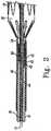
- FIG 1shows an endovascular deployment system, also known as an introducer, for deploying a prosthesis 20 in a lumen of a patient during a medical procedure.
- the introducerincludes an external manipulation section 1, a proximal positioning mechanism or attachment region 2, and a distal positioning mechanism or attachment region 3.
- the external manipulation section 1which is acted upon by a user to manipulate the introducer, remains outside of the patient throughout the procedure.
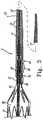
- the prosthesis 20can comprise a tubular graft material, such as Dacron, with self-expanding stents 19 attached thereto as shown in FIGS 2 and 3 .
- the self-expanding stents 19cause the prosthesis 20 to expand during its release from the introducer.
- the prosthesis 20also includes an exposed self-expanding zigzag stent 21 which is a bare wire stent having barbs 26 that extend from the stent distal end. When the self-expanding stent 21 is released, the barbs 26 anchor the distal end of the prosthesis 20 to the surrounding lumen (not shown).
- the prosthesis 20is retained in a compressed condition by a sheath 30.
- the sheath 30radially compresses the prosthesis 20 over a distal portion of a thin walled tube 15.
- the thin walled tube 15is generally flexible and may comprise metal.
- a tube 41which can be made of plastic, is coaxial with and radially outside the thin walled tube 15. The distal end of the tube 41 is adjacent the proximal end of the prosthesis 20.
- the tube 41acts as a pusher to release the prosthesis 20 from the introducer during delivery.
- the tube 41is "thick walled", which is to say the thickness of the wall of tube 41 is several times that of the thin walled tube 15. Preferably, the tube 41 is five or more times thicker than the thin walled tube 15.
- the thick walled tubemay otherwise be known as an elongate pusher.
- the sheath 30is coaxial with and radially outside the thick walled tube 41.
- the thick walled tube 41 and the sheath 30extend proximally to the manipulation region 1, as shown in FIG 5 .
- the thin walled tube 15extends proximally to the proximal end of the introducer, as shown in FIG 7 .
- the introducerfurther includes haemostatic sealing means 31 radially disposed about the sheath and the thick walled tube 41. The haemostatic sealing means 31 control the loss of blood through the introducer during a procedure.
- FIG 2Ashows a sheath 30 according to an aspect of the present invention.
- the sheath 30comprises an outer tube 71, an inner tube 74, and a flat wire coil 75.
- the inner tube 74has a roughened outer surface.
- the flat wire coil 75is compression fitted around the inner tube 74 within the outer tube 71.
- the inner tube 74is made of polytetrafluoro-ethylene (PTFE) and is lubricious and slippery to facilitate insertion and withdrawal of the thick walled tube 41 and of catheters and the like therethrough.
- the outer tube 71may be joined to the roughened outer surface of inner tube 74 between the spacings of the coil in accordance either with the disclosure of U.S. Pat. No. 5,380,304 or U.S. Published Patent Application No.120010034514 .
- the flat wire coil 75provides the sheath 30 with superior kink-resistance.
- the outer tube 71may include a single tube section extending from the proximal to the distal end of the sheath 30.
- the outer tube 71comprises, for example, nylon having a durometer of between about 50 D and 60 D (Shore D hardness). In certain applications, however it may be desirable for the tube section to have a hardness of up to 80D.
- outer tube 71may comprise multiple tube sections of varying hardness arranged axially with the sheath 30.
- outer tube 71comprises a first tube section 72 located on a generally distal portion of the sheath 30 and a second tube section 73 located on a generally proximal portion of the sheath 30.
- the first and second tube sections 72, 73are made of a suitable material, such as Nylon.
- the second tube section 73can comprise, for example, nylon having a durometer of between about 50 D and 60 D, or as high as 80 D.
- the first tube section 72comprises a generally lower durometer material than the second tube section 73.
- the first tube section 72may have a durometer of as low as about 10 D.
- FIG 2illustrates a proximal prosthesis retention and release mechanism of the introducer.
- the proximal retention section 40retains a proximal end 42 of the prosthesis 20 during the procedure.
- the proximal retention section 40is coupled to the thick walled tube 41.
- the proximal retention section 40may be formed in the thick walled tube 41.
- the proximal end 42 of the prosthesis 20comprises an aperture defining a loop 43.
- a proximal trigger wire 44extends through the loop 43 and through an aperture 45 in the proximal attachment section 40 into the annular region between the thin walled tube 15 and the thick walled tube 41.
- the proximal trigger wire 44extends proximally through the introducer from the proximal retention section 40 to the release wire actuation section located in the external manipulation section 1 (See FIG 1 ).
- the trigger wire 44couples the proximal end of the prosthesis 20 to the proximal retention section 40 during deployment.
- the prosthesis 20can be selectively released into the body lumen by disengaging the trigger wire 44 from the loop 43.
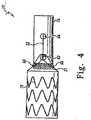
- FIGS 3 and 4illustrate a distal retention and release mechanism of the introducer.
- the distal attachment region 3includes a retention device 10.
- the retention device 10holds the distal end of the self-expanding zigzag stent 21 in a compressed state.
- the self-expanding zigzag stent 21is retained in the retention device 10 by suture loops 66 and a distal trigger wire 22.
- the distal retention device 10includes apertures 62 and 64 to accommodate the distal trigger wire 22.
- the suture loops 66are coupled to the body of the prosthesis 20, and hold the self-expanding zigzag stent 21 in the retention device 10 until the trigger wire 22 is removed.
- the trigger wire 22While the trigger wire 22 is in place, the suture loops 66 prevent the retention device 10 and the prosthesis 20 from separating.
- the trigger wire 22retains the suture loops 66 against an outer surface of the retention device 10.
- the distal trigger wire 22extends proximally through the introducer from the distal retention device 10 to a release wire actuation section located in the manipulation section 1 (See FIG 1 ).
- the suture loops 66are attached to opposing sides of the prosthesis 20, for example separated by 90 to 180 degrees.
- the suture loops 66are generally, inelastic and do not stretch. Since the suture loops 66 do not stretch, they provide opposing torques that prevent the prosthesis 20 from rotating within the retention device 10.
- This configurationdiffers from introducers that have a single point of attachment. Such introducers may allow the stent to rotate within the retention device and lead to entanglement of the stent's struts.
- the suture loops 66are free to move.
- the retention device 10may then be released from the self-expanding zigzag stent 21 by sliding the retention device 10 distally away from the prosthesis 20.
- the retention device 10has at its distal end a long tapered flexible extension 11.
- the flexible extension 11comprises an internal longitudinal aperture 12.
- the longitudinal aperture 12facilitates advancement of the tapered flexible extension 11 along a previously inserted insertion wire 13.
- the longitudinal aperture 12also provides a channel for the introduction of medical reagents. For example, it may be desirable to supply a contrast agent to allow angiography to be performed during placement and deployment phases of the medical procedure.
- the distal end of the thin walled tube 15is coupled to the flexible extension 11.
- the thin walled tube 15is flexible so that the introducer can be advanced within a relatively tortuous vessel, such as a femoral artery.
- the thin walled tubeextends proximally through the introducer to the manipulation section 1, terminating at a connection means 16, as shown in FIG 7 .
- the thin walled tube 15is in mechanical communication with the flexible extension, allowing the operator to axially and rotationally manipulate the distal attachment region 3 with respect to the prosthesis 20.
- the connection means 16is adapted to accept a syringe to facilitate the introduction of reagents into the thin walled tube 15.
- the thin walled tube 15is in fluid communication with the aperture 12 of the flexible extension 11. Therefore, reagents introduced into connection means 16 may pass through aperture 12 and can emanate from lateral apertures 14 into the body lumen.
- FIG 6shows the release wire actuation section of the external manipulation section 1.
- the release wire actuation sectioncomprises an elongate body 36.
- Distal and proximal wire release mechanisms 24, 25are disposed on the elongate body 36.
- End caps 38are disposed on proximal and distal ends of the elongate body 36.
- End caps 38comprise longitudinally-facing laterally opposed surfaces defining distal and proximal stops 88, 89.
- Distal and proximal wire release mechanisms 24, 25are slidably disposed on the elongate body 36 between distal and proximal stops 88, 89.
- Distal and proximal stops 88, 89retain the distal and proximal wire release mechanisms 24, 25 on the elongate body 36.
- the release wire actuation sectioncomprises a locking mechanism 120 for limiting the axial displacement of wire release mechanisms 24, 25 on the elongate body 36.
- the elongate body 36is coupled to and extends longitudinally from the thick walled tube 41.
- the thin walled tube 15passes through a chamber 35 formed longitudinally through the elongate body 36.
- Distal and proximal trigger wires 22, 44extend proximally from the annular space between the thick walled tube 41 and the thin walled tube 15 and into the chamber 35.
- the proximal end of the distal trigger wire 22is coupled to distal wire release mechanism 24.
- the proximal end of the proximal trigger wire 44is coupled to proximal wire release mechanism 25.
- the suture loops 66, the trigger wire 22, and the distal wire release mechanism 24form a control member to selectively release the retention device 10 from the prosthesis 20.
- the proximal trigger wire 44 and the proximal wire release mechanism 25form a control member to selectively release the proximal retention section 40 from the prosthesis 20.
- the distal control memberis actuated by moving the distal wire release mechanism 24 from a distal end to a proximal end of the elongate body 36, thereby disengaging the distal trigger wire 22 from the retention device 10.
- the distal attachment region 3, including the retention device 10can then be slid distally away from the prosthesis 20 allowing the self-expanding stent 21 to expand into the body lumen.
- the proximal control memberis actuated by moving the I proximal wire release mechanism 25 from a distal end to a proximal end of the elongate body 36, thereby disengaging the proximal trigger wire 44 from the prosthesis 20.
- FIG 6Ashows a longitudinal cross-section view of the release wire actuation section in a pre-deployment state.
- Collar 37couples thick walled tube 41 to the elongate body 36.
- Compression member 90 and gasket 92are disposed between the thick walled tube 41 and the elongate body 36 to provide a seal.
- Gasket 92may comprise silicone rubber.
- Distal trigger wire 22is coupled to distal wire release mechanism 24 with a securing member 93.
- proximal trigger wire 44is coupled to proximal wire release mechanism 25 with a securing member 94.
- Securing members 93, 94are adapted to fixedly secure the trigger wires 22, 44 to the respective wire release mechanism 24, 25.
- securing members 93, 94may comprise a pair of clamp blocks 96, 97 and a compression bolt 98 as shown in FIG 6A , wherein the trigger wire is sandwiched between opposed faces of clamp blocks 96, 97 and secured therebetween by the compression bolt 98.
- Alternative designs for securing members 93, 94are contemplated and may be utilized.
- Securing members 93, 94form guide members for guiding trigger wires 22, 44 along the elongate body 36.
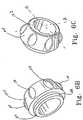
- knob 100may comprise a single unitary body. Alternatively, knob 100 may comprise multiple components. As shown in FIGS 6 and 6A , knob 100 may comprise a body portion 102 and a head portion 104, wherein the head portion 104 is rotatably coupled to the body portion 102 about a longitudinal axis.
- FIG 6Billustrates a perspective view of the distal end of head portion 104.
- the head portion 104comprises a generally cylindrical body having an interior surface and an exterior surface.
- the distal end of head portion 104includes an engaging structure 106 for rotatably coupling the head portion 104 to the body portion 102.
- the engaging structure 106includes an annular flange 108 extending radially from the distal end of the head portion 104.
- the annular flange 108is adapted to engage an annular retaining groove in an inner surface of the body portion proximal end 102 (not shown).
- the head portion 104may include a tactile member 110 on the exterior surface.
- head portion 104may include a plurality of tactile members 110 radially disposed about the exterior surface.
- Tactile members 110may comprise a depression in the surface of the head portion 104.
- tactile members 110may comprise a projection on the surface of the head portion 104.
- Tactile membersmay comprise any shape or size so as to create a textured or non-uniform surface on the head portion 104, thereby giving the operator greater leverage to facilitate rotation of the head portion 104 with respect to the body portion 102.
- the release wire actuation sectionmay comprise a locking mechanism 120 for limiting the axial displacement of wire release mechanism 24, 25 on the elongate body 36.
- Figure 6Aillustrates a locking mechanism 120.
- the rotatable head portion 104 of the wire release mechanism 24, 25is adapted to engage the elongate body 36.
- the locking mechanism 120includes an engageable projection 122 disposed radially inward from the inner radial surface of the head portion 104.
- the locking mechanism 120also includes a recessed portion 124 formed in an exterior surface of the elongate member 36 and adapted to receive the engageable projection 122.
- the head portion 104can be rotated to selectively engage or disengage the engageable projection 122 within the recessed portion 124.
- FIG 6Cillustrates a perspective view of the proximal end of the head portion 104 comprising a portion of a locking mechanism 120.
- the head portion 104comprises a quarter-turn locking mechanism.
- the head portion 104can be rotated ninety degrees in a first direction from a locked position into an unlocked i position.
- the head portion 104can be rotated ninety degrees in a second direction, opposite the first direction from the unlocked position into the locked position.
- the locked positionis indicated by orientation A in which the engageable projection 122 is aligned within the recessed portion 124 of the elongate body 36 (not shown).
- the wire release mechanism 24, 25When the engageable projection 122 engages the recessed portion 124, the wire release mechanism 24, 25 is locked in place, thereby preventing actuation of the respective proximal or distal control member.
- the unlocked positionis indicated by orientation B in which the recessed portion 124 of the elongate body is free of the engageable projection 122, thereby allowing actuation of the respective proximal or distal control member.
- orientation Bthe wire release mechanism 24, 25 is free to slide along the elongate body 36.
- the engageable projectionmay be disposed on the elongate body and the recessed portion may be disposed in the head portion 104.
- FIG 6illustrates a locking mechanism 120 according to another aspect of the present invention.
- the locking mechanismis adapted to limit axial displacement of the wire release mechanisms 24, 25 on the elongate body 36.
- Locking mechanism 120comprises a stay 130.
- Stay 130extends radially through an aperture 132 formed in the elongate body 36.
- the stay 130is coupled to the elongate body 36 through a biasing member 134. Biasing member 134 biases the stay 130 so that a portion of the stay 130 normally extends radially outward of the exterior surface of the elongate body 36.
- Locking mechanism 120allows wire release mechanisms 24, 25 to slide over the stay 130 in a first direction, but prevents wire release mechanisms 24, 25 from sliding over the stay 130 in a second, opposite direction.
- the locking mechanism 120 of FIG 6is configured to allow wire release mechanism 24, 25 to slide from a distal end of the elongate body 36 over the stay 130 to a proximal end of the elongate body 36.
- the locking mechanismprevents the wire release mechanism 24, 25 from returning to the distal end of the elongate body 36 once the wire release mechanism 24, 25 has traversed the stay 130.
- the stay 130comprises a distal contact surface 136 and a proximal contact surface 138.
- the proximal contact surface 138is generally normal to the surface of the elongate member 36 through which the stay 130 extends.
- the distal contact surface 136has an angle relative to the surface of the elongate member 36 through which the stay 130 extends such that when wire release mechanism 24, 25 contacts the stay from a distal end of the elongate member 36, the wire release mechanism 24, 25 exerts a radially inward force on the stay. The force acts on the biasing member, causing the stay 130 to retract into the aperture 132. The release mechanism 24, 25 may thereby traverse the stay 130.
- wire release mechanism 24, 25contacts the stay from a proximal end of the elongate member 36, the wire release mechanism 24, 25 exerts only an axial force on the stay, preventing the stay 130 from retracting through the aperture 132 and the wire release mechanism 24, 25 from traversing the stay 130. Wire release mechanism 24, 25 is thereby prevented from returning to the distal end of the elongate body 36.
- the distal and proximal wire release mechanisms 24, 25Prior to deployment of the prosthesis 20, the distal and proximal wire release mechanisms 24, 25 are positioned on a distal end of the body 36 as shown in FIG 6A .
- the distal wire release mechanism 24is in a generally proximal position with respect to the proximal wire release mechanism 25.
- the positioning of the distal and proximal wire release mechanisms 24 and 25is such that the distal wire release mechanism 24 must be moved before the proximal wire release mechanism 25 can be moved. Therefore, the proximal end 42 of the prosthesis 20 cannot be released until the self-expanding zigzag stent 21 has been released and anchored to the lumen.
- FIG 5shows the haemostatic sealing means 31 of the external manipulation section 1 in greater detail.
- the haemostatic sealing means 31includes a haemostatic seal 27 and a clamping collar 32 that clamps the sheath 30 to the haemostatic seal 27.
- the haemostatic seal 27may also include a seal ring 28 which may be made of silicone.
- the seal ring 28forms a haemostatic seal around the thick walled tube 41.
- the haemostatic sealalso includes a side tube 29 that facilitates the introduction of medical reagents between the thick walled tube 41 and the sheath 30.
- the haemostatic sealing means 31may comprise a haemostatic valve assembly 51 as shown in Figure 5A .
- the haemostatic valve assembly 51includes a cannula body 52, a base member 53 and a rotatable member 54.
- the cannula body 52is positioned at a generally distal portion of the device and the rotatable member 54 is positioned at a generally proximal portion of the device.
- a check valveis disposed longitudinally between cannula body 52 and base member 53.
- the check valvecomprises one or more (three are shown in the embodiment) valve disks 55.
- Valve disks 55are preferably conventional check flow disks. Such valve disks are commercially available, and may be obtained, for example, from Cook, Inc., of Bloomington, Ind., under the name CHECK-FLO® valves. Valve disks 55 include a slit for passage of an interventional device (not shown) therethrough. Preferably, valve disks 55 have a slit on each face thereof. The slits may extend either partially or fully through the disk. Disks of this type are well known in the art. Three valve disks may be stacked and arranged such that the slits are aligned. However, those skilled in the art will appreciate that other numbers of disks may be utilized, and that the slits in the disks need not be aligned.
- An elastomeric valve sheath 56 of the "iris"-typeis disposed between base member 53 and rotatable member 54.
- the rotatable member 54is rotatably coupled with respect to and around a common axis with the base member 53. Iris valves are known in the art and are described, for example,
- a washer 57is provided to secure a distal flange 58 of the iris valve to the base member 53.
- An end cap 60is provided at the proximal end of the device. The end cap 60 secures a proximal flange 59 of the iris valve to the rotatable member 54.
- the elastomeric valve sheath 56comprises a generally cylindrical body 61.
- the valve sheath 56may include a ribbed structure that projects radially into the center of the valve sheath.
- the projecting ribbed structureis believed to enhance the seal formed by the valve sheath by inhibiting the possibility of gap formation when the iris valve is closed.
- the formation of the longitudinal gapscan be problematic with conventional iris seals, particularly when smaller diameter interventional devices are inserted therethrough.
- the ribbed structurecomprises one or more segments that extend circumferentially along part, or all, of the internal circumference of the valve member.
- the ribbed structureis positioned substantially at or near the axial midpoint of the valve sheath.
- the ribbed structurecomprises a plurality of rib members 67. Rib members 67 are circumferentially spaced along inner valve surface 63, and are slightly axially offset from each other. In the embodiment illustrated, three rib members 67 are employed. Each of the rib members 67 spans about one-third of the inner circumference of the valve member, such that in combination as shown, the rib members substantially span the entire inner circumference of the valve member.
- each of the rib members 67preferably overlap slightly as the members are spaced along the circumference of the inner surface of the valve sheath.
- the ribbed membersPreferably, have a generally triangular shape in cross-section, although other shapes may be substituted.
- the iris valveis closed, the presence of the rib members 67 interact to comprise a lock (similar to that provided in well-known plastic locked bags) that is capable of providing a substantially gap-free seal. Further aspects of the haemostatic valve assembly 51 are provided in U.S. Published Patent Application No. 20050171479 .
- blood-lossmay generally be controlled by the check valve by one or more valve disks 55.
- the check valvemay not effectively control blood loss over a wide range of interventional device diameters (for example, 0.0089cm (0.035 in.) to 0.635cm (0.250 in.)).
- the iris-type valvemay be manually adjusted as a backup.
- the iris-type valvemay be adjusted between an open state and a constricted state by manually rotating the rotatable member 54 with respect to the base member 53. Because the distal flange 58 and the proximal flange 59 of the elastomeric Valve sheath 56 are secured to the base member 53 and the rotatable member 54 respectively, rotation of the rotatable member 54 causes an axially intermediate portion (existing between the fixed distal and proximal flanges, 58, 59) of the valve sheath 56 to twist on itself from the open state to the constricted state. As the center opening of the valve is twisted, the valve constricts around the interventional device. Such constriction results in the formation of a haemostatic seal between the valve and the interventional device inserted therethrough.
- FIG 7shows a proximal portion of the external manipulation section 1.
- a pin vise 39is mounted onto the proximal end of the elongate body 36.
- the pin vise 39has a screw cap 46.
- the vise jaws 47clamp against (engage) the thin walled metal tube 15.
- the thin walled tube 15can only move with the body 36, and hence the thin walled tube 15 can only move with the thick walled tube 41 (not shown).
- the introducerincludes a prosthesis control member 81 as illustrated in FIG 1 .
- the prosthesis control member 81is disposed on the dilator portion 34 of the external manipulation section 1.
- the sheath 30is withdrawn proximally over the thick walled tube 41.
- the haemostatic sealing means 31generally fits tightly about the sheath 30, resulting in a great amount of friction between the sheath 30 and the thick walled tube 41.
- withdrawal of the sheath 30 over the thick walled tube 41can be difficult.
- the operatorIn order to overcome the friction, the operator must have a very tight grip on the thick walled tube 41. Axial positioning of the prosthesis 20 may be compromised by the difficulty in gripping the thick walled tube 41.
- the control member 81solves this problem by providing the operator with a better grip on the dilator and by decreasing the force that the operator must exert to control and stabilize the thick walled tube 41 during sheath withdrawal.
- the control member 81is generally tubular and comprises an inner dilator facing surface 82 and.an outer grip surface 83.
- the control member 81is slidably disposed on the thick walled tube 41 between the haemostatic sealing means 31 and the release wire actuation section. This allows the operator to slide the control member 81 (before gripping or squeezing it against dilator portion 34) so that it can be used at any position along the dilator.
- the outer grip surface 83is adapted so that the control member 81 fits the operator's hand comfortably and securely. As such, the outer grip surface 83 may have a diameter that greatly exceeds the diameter of the thick walled tube 41.
- the outer grip surface 83may be generally axially uniform. Alternately, the outer grip surface 83 may be generally axially non-uniform, resulting in a contoured gripping surface.
- FIG 1illustrates a control member 81 having a generally non-uniform outer grip surface 83, wherein the control member is generally shaped like an hour glass.
- the outer grip surface 83may comprise a smooth surface finish, or alternately, the outer grip surface may comprise a rough or textured surface finish. Rough or textured surface finishes are beneficial because they provide increased surface area contact between the operator and the control member 81, thereby increasing the operator's leverage. Multiple surface finishes may be selected to provide various utilitarian and tactile benefits.
- the control member 81is generally deformable so that when the operator grips the control member 81, the control member 81 compresses against the thick walled tube 41.
- the control member 81transfers the force exerted by the operator to the thick walled tube 41.
- the dilator facing surface 82may comprise a generally smooth surface.
- the dilator facing surface 82may have a rough or textured surface. A rough or textured surface may create a more "sticky" or “tacky” contact between the control member 81 and the thick walled tube 41, thereby increasing the force that is transferred by the operator to the dilator.
- the dilator facing surface 82may comprise a generally uniform surface. Alternately, the dilator facing surface 82 may comprise a generally non-uniform surface.
- the dilator gripping surface 82may comprise a plurality of engageable projections that extend radially inward towards the thick walled tube 41. When the operator grips the control member 81 against the thick walled tube 41, engageable projections engage the surface of the thick walled tube. Engageable projections increase the surface contact area between the control member 81 and the thick walled tube, thereby increasing the force that the control member transfers from the operator to the thick walled tube 41.
- Engageable projectionsmay comprise any geometric or non-geometric shape. For example, engageable projections may include "O" shapes, lines, dashes, "V" shapes, or the like.
- Gripping member 81comprises a soft, deformable, or generally low durometer material.
- the gripping member 81may comprise a material with generally tacky surface properties. Accordingly, the gripping member 81 may be made of silicone rubber. Alternatively, in accordance with the present invention, the gripping member may be made of any suitable natural, thermoplastic, or thermoset material known in the art.
- a guide wire 13is introduced, for example, into the femoral artery and advanced until the tip of the guide wire 13 is beyond the region into which the prosthesis 20 is to be deployed.
- the introducer assemblyis then inserted through the femoral artery over the guide wire 13, and positioned by radiographic techniques, generally known in the art.
- the ends of the prosthesis 20are retained by the distal and proximal retaining assemblies respectively and the sheath 30 is disposed over and covers the length of the prosthesis 20.
- the operatorwithdraws the external sheath 30 in a proximal direction from its original position to a position just distal of the proximal attachment section 40.
- the operatorpulls the haemostatic valve assembly 51, and consequently the sheath 30 in a proximal direction while holding the dilator portion 34 steady.
- the surgeonmay grasp the control member 81.
- the control member 81may be slidably positioned at any position along the dilator portion 34 according to the operator's requirements.
- the surgeonBy withdrawing the external sheath 30, the surgeon releases the middle portion of the prosthesis 20 so that the middle portion can expand radially.
- the distal self-expanding stent 21, however,is still retained within the retention device 10 as shown in FIG 3 .
- the proximal end 42 of the prosthesis 20is still retained within the sheath 30 as shown in FIG 2 .
- the operatormay release the pin vise 39, shown in FIG 7 , to allow movement of the thin walled tube 15 with respect to the thick walled tube 41.
- the operatormay make small movements of the thin walled tube to lengthen, shorten, rotate, or compress the prosthesis 20 for accurate placement in the desired location within the lumen.
- X-ray opaque markers(not shown) may be placed along the prosthesis 20 to assist with placement of the prosthesis.
- the distal trigger wife 22is disengaged so that the retention device 10 can separate from the self-expanding zigzag stent 21.
- the distal trigger wire release mechanism 24is disengaged from the elongate body 36 by actuating the locking mechanism 120, shown in FIG 6A .
- the operatorturns the head portion 104 of the knob 100 to release the engageable projection 122 from the recessed portion 124 of the elongate body 36, allowing the release mechanism 24 to move freely along the elongate body 36.
- the operatorslides the knob 100 proximally to a proximal end of the elongate body 36.
- the proximal stop 89retains the release mechanism 24 on the elongate body 36.
- the knob 100moves the distal wire guide proximally in the chamber 35, causing the trigger wire 22 to disengage from the retention device 10 (shown in FIG 3 ).
- the knob 120traverses the stay 130. Once the distal trigger wire release mechanism 24 is slid to the proximal end of the body 36, as shown in FIG 6 , the locking mechanism 120 prevents the distal trigger wire release mechanism 24 from returning to its original position.
- the screw cap 46 of the pin vise 39(shown in FIG 7 ) is loosened so that the thin walled tube 15 can be pushed in a distal direction, thereby moving the retention device 10 in a distal direction.
- the distal attachment means 10no longer surrounds the self-expanding stent 21 at the distal end of the prosthesis 20, the self-expanding stent 21 can expand.
- the hooks or barbs 26 on the self-expanding stent 21grip onto the walls of the lumen to hold the distal end of the prosthesis 20 in place.
- the proximal end 42 of the prosthesis 20is still retained by the proximal retention section 40.
- the proximal trigger wire 44extends through the loop 43, retaining the prosthesis 20 to the delivery system, as shown in FIG 2 .
- the external sheath 30is withdrawn to proximal of the proximal attachment section 40 to allow the proximal end 42 of the prosthesis 20 to expand.
- the proximal end 42 of the prosthesis 20is not anchored in the body lumen and may still be moved. Consequently, the prosthesis 20 can be rotated or lengthened or shortened or otherwise moved for accurate positioning. Where the prosthesis 20 to be deployed is a bifurcated graft, the movement at this stage may ensure that the shorter leg is directed in the direction of the contra-iliac artery.
- the proximal end 42 of the prosthesis 20is released by disengaging the proximal trigger wire 44.
- the proximal trigger wire release mechanism 25(shown in FIG 6A ) is disengaged from the elongate body 36 by actuating the locking mechanism 120 as described above with respect to the distal wire release mechanism 24.
- the operatorslides the knob 100, proximally from its initial position at the distal end of the elongate body 36 (shown in FIG 6 ) to a proximal end of the body 36.
- the knob 100moves the proximal wire guide proximally in the chamber 35, causing the trigger wire 44 to disengage from the prosthesis 20.
- the knob 100traverses the stay 130. Once the proximal trigger wire release mechanism 25 is slid to the proximal end of the body 36, the locking mechanism 129 prevents the release mechanism 25 from returning to its original position. At this point, the proximal trigger wire release mechanism 25 is situated adjacent the distal trigger wire release mechanism 24. The loop 43 of the terminal distal self-expanding zigzag stent 19 is hence released, and the prosthesis 20 is free and expands to the walls of the vessel.
- the introduceris ready to be removed.
- the proximal attachment section 40is advanced until it is received in the rear of the distal attachment device 10.
- the distal attachment device 10, the tapered flexible extension 11, the proximal attachment device 40, and the sheathmay then be removed together. Alternatively, the sheath can be removed at a later time than ,the other items.
- An advantage of the release wire mechanisms of the above-described embodimentsis that the release of each of the prosthesis retaining devices is relatively convenient quick and simple. This contrasts with prior art arrangements comprising removable rings with set screws in which a relatively long and complicated procedure is necessary to remove the set screw, to pull and remove the ring and then to pull the entire release wire from the introducer.
- An advantage of the flexible sheath 30is that it can maintain a round, smooth shape even in areas where it constricts or holds the stent graft in the tightly packed, folded configuration. This allows a smoother, easier retraction of the sheath from off the prosthesis at deployment. In addition, the sheath 30 is kink resistant due to its coil reinforcement in the wall.
- sheath 30substantially eliminates the chance for sheath kinking while remaining flexible enough to negotiate tortuous anatomy and the aortic arch. Flexibility and the ability to contain a folded or collapsed stent graft or other prosthesis are opposing constraints.
- the usual PTFE sheath materialis a compromise for both requirements.
- the construction of sheath 30has increased flexibility with increased resistance to kinking and diametrical deformation (ability to maintain a round shape and a smooth lumen).
- An advantage of the different types of control elements for the various mechanisms of the introducer devicemakes it possible to an operator to manipulate the delivery system without having to look directly at the various parts of the device.
- Each componenthas a feel that communicates to the operator what it is and what motions it requires. This is important to the operator because he or she normally watches the progress of the stent graft placement and deployment on a fluoroscope which is above the patient usually at the operator's eye level. Not having to look back and forth between the fluoroscope and the delivery system allows the operator to concentrate without interruption on the actual placement and deployment of the stent graft.
- valve 56in addition to valve assembly 51 is to control any blood seepage around assembly 51.
- the extra valvealso provides safety redundancy in that if one valve fails, the other valve can control bleeding to a safe amount.
- the prosthesis 20may not be self-expanding; it could be a balloon-expandable I prosthesis, although this would require a more complicated introducer arrangement.
- the inventionis not limited to any one of these but may reside in two or more of these combined together. Accordingly, the invention is not to be restricted except in light of the attached claims and their equivalents.
Landscapes
- Health & Medical Sciences (AREA)
- Engineering & Computer Science (AREA)
- Biomedical Technology (AREA)
- Cardiology (AREA)
- Oral & Maxillofacial Surgery (AREA)
- Transplantation (AREA)
- Heart & Thoracic Surgery (AREA)
- Vascular Medicine (AREA)
- Life Sciences & Earth Sciences (AREA)
- Animal Behavior & Ethology (AREA)
- General Health & Medical Sciences (AREA)
- Public Health (AREA)
- Veterinary Medicine (AREA)
- Prostheses (AREA)
- Media Introduction/Drainage Providing Device (AREA)
Description
- This invention relates to a medical device and, in particular an introducer and a means for retaining and releasing an expandable, intraluminal prosthesis for the endovascular repair of diseased or damaged vessels.
- Throughout this specification the terms distal and distally are used for a position or direction towards the patient's heart and the terms proximal and proximally are used for a position or direction away from the patient's heart.
- The deployment of intraluminal prostheses into the lumen of a patient from a remote location by the use of a deployment device or introducer has been disclosed in a number of patents and patent applications. For example, United States Patent No.
4,562,596 entitled "Aortic Graft, Device and Method for Performing an Intraluminal Abdominal Aortic Aneurysm Repair", proposes the retention of a self expanding graft within a sleeve until it is to be deployed, at which time the sleeve is withdrawn and the graft is allowed to expand. United States Patent No.4,665,918 entitled "Prosthesis System and Method", proposes a system and method for the deployment of a prosthesis in a blood vessel. The prosthesis is positioned between a delivery catheter and an outer sheath and expands outwardly upon removal of the sheath. - United States Published Patent Application No.
20050060018 entitled "Prosthesis Deployment System," discloses an introducer for an expandable endovascular prosthesis. A self-expanding prosthesis is radially disposed within a distal portion of an outer sheath. A dilator or positioner is radially disposed within a proximal portion of the outer sheath so that the dilator distal end engages the prosthesis proximal end. To deploy the prosthesis, the operator withdraws the outer sheath over the dilator portion and the prosthesis while holding the dilator portion steady, thereby exposing the prosthesis and allowing the prosthesis to expand radially outwardly. In practice, the outer sheath fits tightly over the dilator. Because of the tight fit, withdrawal of the sheath can be difficult, requiring a very tight grip on the dilator by the operator. However, the dilator has a relatively small diameter and does not provide an adequate gripping surface. There is a need in the art for an improved prosthesis deployment system that addresses this issue. - The outer sheath of a prosthesis deployment system should be flexible and capable of conforming to highly tortuous body lumen systems without deforming or kinking. The outer sheath should also be strong and capable of maintaining its shape during delivery. United States Patent No.
5,380,304 entitled "Flexible, Kink-Resistant, introducer Sheath and Method of Manufacture," discloses an apparatus and method of manufacturing an introducer sheath for percutaneous vascular access. United States Published Patent Application No.20010034514 entitled "Introducer Sheath," discloses an improved introducer sheath apparatus. There is a need in the art for an improved prosthesis deployment system that addresses this issue. - Today, many endoluminal prostheses are radially self-expanding. Radially self-expanding prostheses are advantageous because they do not require complicated and bulky balloon catheter systems for deployment. Such prostheses present a challenge, however, in that once a prosthesis end is released and anchored into the body lumen, subsequent positioning can be difficult. This is particularly the case if the ends of the prosthesis include anchoring mechanisms to secure the prosthesis to the body lumen. As a consequence, many deployment devices have been proposed that allow the self-expanding prosthesis to be partially expanded while providing a mechanism for retaining the prosthesis ends until the prosthesis has been properly positioned.
- For example, in United States Published Patent Application No.
20050060018 , discussed above, the introducer comprises a retention section for retaining a proximal end of the prosthesis thereto. The proximal end of the prosthesis is retained by a trigger wire. The trigger wire can be removed from the introducer to release the proximal end of the prosthesis into the body lumen. The deployment system disclosed in United States Published Patent Application No.20050060018 has various advantages over other delivery systems including that it provides the operator with greater control over the prosthesis during deployment before the proximal prosthesis end is released into the body lumen. However, it can be inconvenient and awkward for the operator to have to remove and store the trigger wire during a procedure. There is a need in the art for a prosthesis deployment system that has a trigger wire mechanism for retaining a prosthesis end, wherein the prosthesis end can be deployed without having to remove the trigger wire. - United States Published Patent Application No.
20050085890 entitled "Prosthesis Deployment System Retention Device," discloses another introducer for an expandable endovascular prosthesis. The introducer comprises a retention section for retaining a proximal end of the prosthesis thereto, similar to that of United States Published Patent Application No,20050060018 . The introducer comprises an additional retention section for retaining a distal end of the prosthesis thereto. The prosthesis is retained in the distal retention section by a second trigger wire. The second trigger wire is removed from the introducer to release the distal end of the prosthesis into the body lumen. The invention disclosed in United States Published Patent Application No.20050085890 has many of the same advantages and challenges of United States Published Patent Application No.20050060018 described above. PCT Patent Publication Number No. WO98/53761 20030233140 entitled "Trigger Wire System," and United States Published Patent Application No.20040098079 entitled "Thoracic Aortic Stent Graft Deployment Device" each disclose introducer devices having trigger wires that are adapted for retaining a portion of a prosthesis during deployment.- Many prosthesis delivery systems have haemostatic valve assemblies for controlling blood loss through the system during the procedure. Valve assemblies are disposed on the introducer and are adapted to provide a radial seal about various interventional devices used during the procedure. Valve sealing assemblies may comprise disk type automatic or self closing valves. Disk type valves have various advantages including that they are relatively inexpensive and they provide an adequate seal around a variety of interventional devices having a range of diameters. However, no single disk valve is capable of sealing over the entire range of interventional device diameters, for example between 0.089cm (0.035 inches) and 0.635cm (0.250 inches). United States Published Patent Application No.
20050171479 entitled "Hemostatic Valve Assembly" discloses an iris-type valve assembly for controlling a flow of liquid. There is a need in the art for a prosthesis deployment system having an improved haemostatic valve assembly that addresses this issue. - Finally, various published patent applications and patents disclose features that relate to various aspects of prosthesis deployment systems. These include, but are not limited to:
- a. United States Published Patent Application No.
20040054396 entitled "Stent-Graft Fastening," discloses arrangements for fastening stents onto grafts particularly for exposed stents. - b.
PCT Patent Publication Number No. WO031053287 - c. United States Patent No.
5,720,776 entitled "Expandable Transluminal Graft Prosthesis for Repair of Aneurysm," discloses improved barbs with various forms of mechanical attachment to a stent. - d. United States Patent No.
6,206,931 entitled "Graft Prosthesis Materials," discloses graft prosthesis materials and a method for implanting, transplanting replacing and repairing a part of a patient and particularly the manufacture and use of a purified, collagen based matrix structure removed from a submucosa tissue source. - e.
PCT Patent Publication Number No. WO99/29262 - f.
PCT Patent Publication Number No. WO03/034948 - g.
EP0972536 discloses a surgical catheter having an auxiliary grip which can clamp onto the area of the catheter not inserted into the body. The auxiliary grip provides additional support to the main grip. The auxiliary grip can be released and expanded for movement. - The invention is defined as in claim 1; in a further aspect, there is provided a trigger wire release mechanism for releasing a retained end of a prosthesis, the trigger wire release mechanism comprising:a prosthesis retaining device arranged to engage an end of the prosthesis;a trigger wire having a distal end and a proximal end, the distal end being arranged to selectively couple the prosthesis retaining device to the prosthesis; a control mechanism comprising an elongate body member and a guide member, the elongate body member having a proximal end and a distal end, an exterior surface, and an interior surface, the interior surface defining a chamber extending longitudinally with the elongate body member; wherein the trigger wire proximal end is operably coupled to the guide member in the chamber and the guide member is slidably disposed between a generally distal position and a generally proximal position along the elongate body member to selectively disengage the prosthesis retaining device from the prosthesis. The trigger wire release mechanism may comprise a locking mechanism to selectively limit axial displacement of the guide member on the elongate body member. The trigger wire release mechanism may comprise a stop disposed on the distal end of the elongate body member to retain the guide member on the elongate body member. The trigger wire release mechanism may comprise first and second trigger wires attached to respective first and second prosthesis retaining devices located at opposite ends of the prosthesis.
- In accordance with a second aspect, there is provided an introducer for a prosthesis, the introducer comprising a trigger wire release mechanism according to the first aspect as defined in claim 1, the invention defines an introducer for a prosthesis, the introducer comprising: an elongate pusher having a distal end in communication with a proximal end of the prosthesis; a flexible sheath slidably disposed over the elongate pusher, the flexible sheath releasably covering the prosthesis in a compressed state, wherein the prosthesis is arranged to be released by withdrawing the flexible sheath proximally over the elongate pusher while controlling the position of the prosthesis; and a control member disposed on a proximal portion of the elongate pusher capable of transferring a force between an operator and the elongate pusher for controlling the position of the prosthesis while the sheath is withdrawn from the prosthesis.
- The control member comprises a generally deformable tubular body disposed about the elongate pusher. The control member is capable of transferring force between an operator and the elongate pusher by comprising an inner lumen surface adapted to grip the elongate member. The control member may be slidably disposed along the elongate pusher.
- In another aspect of the invention, the introducer may comprise a haemostatic valve assembly for controlling blood loss during a procedure. The haemostatic valve assembly is radially disposed about a proximal end of the flexible sheath.; The haemostatic valve assembly includes a disc valve and an iris-type valve.
- In another aspect of the invention, the introducer may comprise a flexible sheath that releasably covers the prosthesis in a compressed state and an elongate pusher disposed within the flexible sheath and having a distal end in communication, with a proximal end of the prosthesis. A distal portion of the flexible sheath may comprise a kink-resistant sandwich construction including an elongate inner tube having a passageway extending longitudinally therethrough, a coil having a plurality of longitudinally-positioned turns defining a plurality of spaces therebetween, and an elongate outer tube disposed longitudinally around the coil and the inner tube. The inner tube and the outer tube are connected through the spaces between the coil turns.
FIG 1 is a perspective view of selected segments of an introducer of the present invention with a prosthesis partially deployed.FIG 2 is a sectional detail view of a portion of the introducer illustrating the proximal end of the prosthesis.FIG 2A is a sectional cutaway view of a portion of an introducer sheath.FIG 3 is a sectional detail view of a portion of the introducer illustrating the distal end of the prosthesis.FIG 4 is a sectional view of a distal retention device of the introducer.FIG 5 is a sectional view of a portion of the introducer illustrating the i haemostatic sealing means.FIG 5A is a sectional view of a haemostatic valve assembly.FIG 6 is a perspective view of a trigger wire release mechanism of an introducer.FIG 6A is a sectional detail view of a trigger wire release mechanism of an introducer.FIG 6B is a perspective view of a portion of a trigger wire knob.FIG 6C is another perspective view of a portion of a trigger wire knob.FIG 7 is a sectional view of a portion of the introducer illustrating the pin vise clamp and the medical reagent introduction tube.FIG 1 shows an endovascular deployment system, also known as an introducer, for deploying aprosthesis 20 in a lumen of a patient during a medical procedure. The introducer includes an external manipulation section 1, a proximal positioning mechanism or attachment region 2, and a distal positioning mechanism or attachment region 3. During a medical procedure to deploy theprosthesis 20, the proximal and distal attachment regions 2 and 3 will travel through the lumen to a desired deployment site. The external manipulation section 1, which is acted upon by a user to manipulate the introducer, remains outside of the patient throughout the procedure.- The
prosthesis 20 can comprise a tubular graft material, such as Dacron, with self-expandingstents 19 attached thereto as shown inFIGS 2 and3 . The self-expandingstents 19 cause theprosthesis 20 to expand during its release from the introducer. Theprosthesis 20 also includes an exposed self-expandingzigzag stent 21 which is a bare wire stent having barbs 26 that extend from the stent distal end. When the self-expandingstent 21 is released, the barbs 26 anchor the distal end of theprosthesis 20 to the surrounding lumen (not shown). - The
prosthesis 20 is retained in a compressed condition by asheath 30. Thesheath 30 radially compresses theprosthesis 20 over a distal portion of a thinwalled tube 15. The thinwalled tube 15 is generally flexible and may comprise metal. Atube 41, which can be made of plastic, is coaxial with and radially outside the thinwalled tube 15. The distal end of thetube 41 is adjacent the proximal end of theprosthesis 20. Thetube 41 acts as a pusher to release theprosthesis 20 from the introducer during delivery. - The
tube 41 is "thick walled", which is to say the thickness of the wall oftube 41 is several times that of the thinwalled tube 15. Preferably, thetube 41 is five or more times thicker than the thinwalled tube 15. The thick walled tube may otherwise be known as an elongate pusher. Thesheath 30 is coaxial with and radially outside the thickwalled tube 41. The thickwalled tube 41 and thesheath 30 extend proximally to the manipulation region 1, as shown inFIG 5 . The thinwalled tube 15 extends proximally to the proximal end of the introducer, as shown inFIG 7 . The introducer further includes haemostatic sealing means 31 radially disposed about the sheath and the thickwalled tube 41. The haemostatic sealing means 31 control the loss of blood through the introducer during a procedure. FIG 2A shows asheath 30 according to an aspect of the present invention. Thesheath 30 comprises anouter tube 71, aninner tube 74, and aflat wire coil 75. Theinner tube 74 has a roughened outer surface. Theflat wire coil 75 is compression fitted around theinner tube 74 within theouter tube 71. Theinner tube 74 is made of polytetrafluoro-ethylene (PTFE) and is lubricious and slippery to facilitate insertion and withdrawal of the thickwalled tube 41 and of catheters and the like therethrough. Theouter tube 71 may be joined to the roughened outer surface ofinner tube 74 between the spacings of the coil in accordance either with the disclosure ofU.S. Pat. No. 5,380,304 orU.S. Published Patent Application No.120010034514 flat wire coil 75 provides thesheath 30 with superior kink-resistance.- The
outer tube 71 may include a single tube section extending from the proximal to the distal end of thesheath 30. In this case, theouter tube 71 comprises, for example, nylon having a durometer of between about 50 D and 60 D (Shore D hardness). In certain applications, however it may be desirable for the tube section to have a hardness of up to 80D. - Alternatively, in applications where it is desirable to have a highly flexible leading end of the
sheath 30, for example where thesheath 30 must negotiate small, tortuous vessels,outer tube 71 may comprise multiple tube sections of varying hardness arranged axially with thesheath 30. For example, inFIG 2A ,outer tube 71 comprises afirst tube section 72 located on a generally distal portion of thesheath 30 and asecond tube section 73 located on a generally proximal portion of thesheath 30. The first andsecond tube sections second tube section 73 can comprise, for example, nylon having a durometer of between about 50 D and 60 D, or as high as 80 D. Thefirst tube section 72 comprises a generally lower durometer material than thesecond tube section 73. For example, thefirst tube section 72 may have a durometer of as low as about 10 D. FIG 2 illustrates a proximal prosthesis retention and release mechanism of the introducer. Theproximal retention section 40 retains aproximal end 42 of theprosthesis 20 during the procedure. Theproximal retention section 40 is coupled to the thickwalled tube 41. Alternatively, theproximal retention section 40 may be formed in the thickwalled tube 41. Theproximal end 42 of theprosthesis 20 comprises an aperture defining aloop 43. Aproximal trigger wire 44 extends through theloop 43 and through anaperture 45 in theproximal attachment section 40 into the annular region between the thinwalled tube 15 and the thickwalled tube 41. Theproximal trigger wire 44 extends proximally through the introducer from theproximal retention section 40 to the release wire actuation section located in the external manipulation section 1 (SeeFIG 1 ). Thetrigger wire 44 couples the proximal end of theprosthesis 20 to theproximal retention section 40 during deployment. Theprosthesis 20 can be selectively released into the body lumen by disengaging thetrigger wire 44 from theloop 43.FIGS 3 and4 illustrate a distal retention and release mechanism of the introducer. The distal attachment region 3 includes aretention device 10. Theretention device 10 holds the distal end of the self-expandingzigzag stent 21 in a compressed state. The self-expandingzigzag stent 21 is retained in theretention device 10 bysuture loops 66 and adistal trigger wire 22. Thedistal retention device 10 includesapertures distal trigger wire 22. Thesuture loops 66 are coupled to the body of theprosthesis 20, and hold the self-expandingzigzag stent 21 in theretention device 10 until thetrigger wire 22 is removed. While thetrigger wire 22 is in place, thesuture loops 66 prevent theretention device 10 and theprosthesis 20 from separating. Thetrigger wire 22 retains thesuture loops 66 against an outer surface of theretention device 10. Thedistal trigger wire 22 extends proximally through the introducer from thedistal retention device 10 to a release wire actuation section located in the manipulation section 1 (SeeFIG 1 ).- As shown in
FIG 4 , thesuture loops 66 are attached to opposing sides of theprosthesis 20, for example separated by 90 to 180 degrees. Thesuture loops 66 are generally, inelastic and do not stretch. Since thesuture loops 66 do not stretch, they provide opposing torques that prevent theprosthesis 20 from rotating within theretention device 10. This configuration differs from introducers that have a single point of attachment. Such introducers may allow the stent to rotate within the retention device and lead to entanglement of the stent's struts. When thetrigger wire 22 is removed, thesuture loops 66 are free to move. Theretention device 10 may then be released from the self-expandingzigzag stent 21 by sliding theretention device 10 distally away from theprosthesis 20. - The
retention device 10 has at its distal end a long taperedflexible extension 11. Theflexible extension 11 comprises an internallongitudinal aperture 12. Thelongitudinal aperture 12 facilitates advancement of the taperedflexible extension 11 along a previously insertedinsertion wire 13. Thelongitudinal aperture 12 also provides a channel for the introduction of medical reagents. For example, it may be desirable to supply a contrast agent to allow angiography to be performed during placement and deployment phases of the medical procedure. - The distal end of the thin
walled tube 15 is coupled to theflexible extension 11. The thinwalled tube 15 is flexible so that the introducer can be advanced within a relatively tortuous vessel, such as a femoral artery. The thin walled tube extends proximally through the introducer to the manipulation section 1, terminating at a connection means 16, as shown inFIG 7 . The thinwalled tube 15 is in mechanical communication with the flexible extension, allowing the operator to axially and rotationally manipulate the distal attachment region 3 with respect to theprosthesis 20. The connection means 16 is adapted to accept a syringe to facilitate the introduction of reagents into the thinwalled tube 15. The thinwalled tube 15 is in fluid communication with theaperture 12 of theflexible extension 11. Therefore, reagents introduced into connection means 16 may pass throughaperture 12 and can emanate from lateral apertures 14 into the body lumen. FIG 6 shows the release wire actuation section of the external manipulation section 1. The release wire actuation section comprises anelongate body 36. Distal and proximalwire release mechanisms elongate body 36. End caps 38 are disposed on proximal and distal ends of theelongate body 36. End caps 38 comprise longitudinally-facing laterally opposed surfaces defining distal andproximal stops wire release mechanisms elongate body 36 between distal andproximal stops proximal stops wire release mechanisms elongate body 36. The release wire actuation section comprises alocking mechanism 120 for limiting the axial displacement ofwire release mechanisms elongate body 36.- The
elongate body 36 is coupled to and extends longitudinally from the thickwalled tube 41. The thinwalled tube 15 passes through achamber 35 formed longitudinally through theelongate body 36. Distal andproximal trigger wires 22, 44 (FIGS 3 and2 , respectively) extend proximally from the annular space between the thickwalled tube 41 and the thinwalled tube 15 and into thechamber 35. The proximal end of thedistal trigger wire 22 is coupled to distalwire release mechanism 24. The proximal end of theproximal trigger wire 44 is coupled to proximalwire release mechanism 25. - The
suture loops 66, thetrigger wire 22, and the distalwire release mechanism 24 form a control member to selectively release theretention device 10 from theprosthesis 20. Theproximal trigger wire 44 and the proximalwire release mechanism 25 form a control member to selectively release theproximal retention section 40 from theprosthesis 20. To release theretention device 10 from the prosthesis, the distal control member is actuated by moving the distalwire release mechanism 24 from a distal end to a proximal end of theelongate body 36, thereby disengaging thedistal trigger wire 22 from theretention device 10. The distal attachment region 3, including theretention device 10 can then be slid distally away from theprosthesis 20 allowing the self-expandingstent 21 to expand into the body lumen. To release theprosthesis 20 from theproximal retention section 40, the proximal control member is actuated by moving the I proximalwire release mechanism 25 from a distal end to a proximal end of theelongate body 36, thereby disengaging theproximal trigger wire 44 from theprosthesis 20. FIG 6A shows a longitudinal cross-section view of the release wire actuation section in a pre-deployment state.Collar 37 couples thickwalled tube 41 to theelongate body 36. Compression member 90 andgasket 92 are disposed between the thickwalled tube 41 and theelongate body 36 to provide a seal.Gasket 92 may comprise silicone rubber.Distal trigger wire 22 is coupled to distalwire release mechanism 24 with a securingmember 93. Similarly,proximal trigger wire 44 is coupled to proximalwire release mechanism 25 with a securingmember 94. Securingmembers trigger wires wire release mechanism members compression bolt 98 as shown inFIG 6A , wherein the trigger wire is sandwiched between opposed faces of clamp blocks 96, 97 and secured therebetween by thecompression bolt 98. Alternative designs for securingmembers members trigger wires elongate body 36.- Distal and proximal
wire release mechanisms elongate body 36 to form aknob 100.Knob 100 may comprise a single unitary body. Alternatively,knob 100 may comprise multiple components. As shown inFIGS 6 and6A ,knob 100 may comprise abody portion 102 and ahead portion 104, wherein thehead portion 104 is rotatably coupled to thebody portion 102 about a longitudinal axis.FIG 6B illustrates a perspective view of the distal end ofhead portion 104. Thehead portion 104 comprises a generally cylindrical body having an interior surface and an exterior surface. The distal end ofhead portion 104 includes an engagingstructure 106 for rotatably coupling thehead portion 104 to thebody portion 102. The engagingstructure 106 includes anannular flange 108 extending radially from the distal end of thehead portion 104. Theannular flange 108 is adapted to engage an annular retaining groove in an inner surface of the body portion proximal end 102 (not shown). - The
head portion 104 may include atactile member 110 on the exterior surface. Alternately,head portion 104 may include a plurality oftactile members 110 radially disposed about the exterior surface.Tactile members 110 may comprise a depression in the surface of thehead portion 104. Alternately,tactile members 110 may comprise a projection on the surface of thehead portion 104. Tactile members may comprise any shape or size so as to create a textured or non-uniform surface on thehead portion 104, thereby giving the operator greater leverage to facilitate rotation of thehead portion 104 with respect to thebody portion 102. - The release wire actuation section may comprise a
locking mechanism 120 for limiting the axial displacement ofwire release mechanism elongate body 36.Figure 6A illustrates alocking mechanism 120. Therotatable head portion 104 of thewire release mechanism elongate body 36. Thelocking mechanism 120 includes anengageable projection 122 disposed radially inward from the inner radial surface of thehead portion 104. Thelocking mechanism 120 also includes a recessedportion 124 formed in an exterior surface of theelongate member 36 and adapted to receive theengageable projection 122. Thehead portion 104 can be rotated to selectively engage or disengage theengageable projection 122 within the recessedportion 124. FIG 6C illustrates a perspective view of the proximal end of thehead portion 104 comprising a portion of alocking mechanism 120. Thehead portion 104 comprises a quarter-turn locking mechanism. Thehead portion 104 can be rotated ninety degrees in a first direction from a locked position into an unlocked i position. Similarly, thehead portion 104 can be rotated ninety degrees in a second direction, opposite the first direction from the unlocked position into the locked position. The locked position is indicated by orientation A in which theengageable projection 122 is aligned within the recessedportion 124 of the elongate body 36 (not shown). When theengageable projection 122 engages the recessedportion 124, thewire release mechanism portion 124 of the elongate body is free of theengageable projection 122, thereby allowing actuation of the respective proximal or distal control member. In orientation B, thewire release mechanism elongate body 36.- Alternative locking mechanisms within the scope of the present invention are contemplated. For example, the engageable projection may be disposed on the elongate body and the recessed portion may be disposed in the
head portion 104. FIG 6 illustrates alocking mechanism 120 according to another aspect of the present invention. The locking mechanism is adapted to limit axial displacement of thewire release mechanisms elongate body 36.Locking mechanism 120 comprises astay 130. Stay 130 extends radially through anaperture 132 formed in theelongate body 36. Thestay 130 is coupled to theelongate body 36 through a biasing member 134. Biasing member 134 biases thestay 130 so that a portion of thestay 130 normally extends radially outward of the exterior surface of theelongate body 36.Locking mechanism 120 allowswire release mechanisms stay 130 in a first direction, but preventswire release mechanisms stay 130 in a second, opposite direction. For example, thelocking mechanism 120 ofFIG 6 is configured to allowwire release mechanism elongate body 36 over thestay 130 to a proximal end of theelongate body 36. However, the locking mechanism prevents thewire release mechanism elongate body 36 once thewire release mechanism stay 130.- The
stay 130 comprises adistal contact surface 136 and aproximal contact surface 138. Theproximal contact surface 138 is generally normal to the surface of theelongate member 36 through which thestay 130 extends. Thedistal contact surface 136 has an angle relative to the surface of theelongate member 36 through which thestay 130 extends such that whenwire release mechanism elongate member 36, thewire release mechanism stay 130 to retract into theaperture 132. Therelease mechanism stay 130. Conversely, whenwire release mechanism elongate member 36, thewire release mechanism stay 130 from retracting through theaperture 132 and thewire release mechanism stay 130.Wire release mechanism elongate body 36. - Prior to deployment of the
prosthesis 20, the distal and proximalwire release mechanisms body 36 as shown inFIG 6A . The distalwire release mechanism 24 is in a generally proximal position with respect to the proximalwire release mechanism 25. The positioning of the distal and proximalwire release mechanisms wire release mechanism 24 must be moved before the proximalwire release mechanism 25 can be moved. Therefore, theproximal end 42 of theprosthesis 20 cannot be released until the self-expandingzigzag stent 21 has been released and anchored to the lumen. FIG 5 shows the haemostatic sealing means 31 of the external manipulation section 1 in greater detail. The haemostatic sealing means 31 includes ahaemostatic seal 27 and aclamping collar 32 that clamps thesheath 30 to thehaemostatic seal 27. Thehaemostatic seal 27 may also include aseal ring 28 which may be made of silicone. Theseal ring 28 forms a haemostatic seal around the thickwalled tube 41. The haemostatic seal also includes aside tube 29 that facilitates the introduction of medical reagents between the thickwalled tube 41 and thesheath 30.- The haemostatic sealing means 31 may comprise a
haemostatic valve assembly 51 as shown inFigure 5A . Thehaemostatic valve assembly 51 includes acannula body 52, abase member 53 and a rotatable member 54. Thecannula body 52 is positioned at a generally distal portion of the device and the rotatable member 54 is positioned at a generally proximal portion of the device. A check valve is disposed longitudinally betweencannula body 52 andbase member 53. In the embodiment shown, the check valve comprises one or more (three are shown in the embodiment)valve disks 55. Valve disks 55 are preferably conventional check flow disks. Such valve disks are commercially available, and may be obtained, for example, from Cook, Inc., of Bloomington, Ind., under the name CHECK-FLO® valves.Valve disks 55 include a slit for passage of an interventional device (not shown) therethrough. Preferably,valve disks 55 have a slit on each face thereof. The slits may extend either partially or fully through the disk. Disks of this type are well known in the art. Three valve disks may be stacked and arranged such that the slits are aligned. However, those skilled in the art will appreciate that other numbers of disks may be utilized, and that the slits in the disks need not be aligned.- An
elastomeric valve sheath 56 of the "iris"-type is disposed betweenbase member 53 and rotatable member 54. The rotatable member 54 is rotatably coupled with respect to and around a common axis with thebase member 53. Iris valves are known in the art and are described, for example, U.S. Pat. No. 5,158,553 . Awasher 57 is provided to secure adistal flange 58 of the iris valve to thebase member 53. Anend cap 60 is provided at the proximal end of the device. Theend cap 60 secures aproximal flange 59 of the iris valve to the rotatable member 54.- The
elastomeric valve sheath 56 comprises a generallycylindrical body 61. Thevalve sheath 56 may include a ribbed structure that projects radially into the center of the valve sheath. The projecting ribbed structure is believed to enhance the seal formed by the valve sheath by inhibiting the possibility of gap formation when the iris valve is closed. The formation of the longitudinal gaps can be problematic with conventional iris seals, particularly when smaller diameter interventional devices are inserted therethrough. - The ribbed structure comprises one or more segments that extend circumferentially along part, or all, of the internal circumference of the valve member. Preferably, the ribbed structure is positioned substantially at or near the axial midpoint of the valve sheath. In the embodiment shown, the ribbed structure comprises a plurality of
rib members 67.Rib members 67 are circumferentially spaced alonginner valve surface 63, and are slightly axially offset from each other. In the embodiment illustrated, threerib members 67 are employed. Each of therib members 67 spans about one-third of the inner circumference of the valve member, such that in combination as shown, the rib members substantially span the entire inner circumference of the valve member. The longitudinal ends of each of therib members 67 preferably overlap slightly as the members are spaced along the circumference of the inner surface of the valve sheath. Preferably, the ribbed members have a generally triangular shape in cross-section, although other shapes may be substituted. When the iris valve is closed, the presence of therib members 67 interact to comprise a lock (similar to that provided in well-known plastic locked bags) that is capable of providing a substantially gap-free seal. Further aspects of thehaemostatic valve assembly 51 are provided inU.S. Published Patent Application No. 20050171479 . - During a procedure, blood-loss may generally be controlled by the check valve by one or
more valve disks 55. The check valve, however may not effectively control blood loss over a wide range of interventional device diameters (for example, 0.0089cm (0.035 in.) to 0.635cm (0.250 in.)). Where the check valve is insufficient to control blood loss, the iris-type valve may be manually adjusted as a backup. - The iris-type valve may be adjusted between an open state and a constricted state by manually rotating the rotatable member 54 with respect to the
base member 53. Because thedistal flange 58 and theproximal flange 59 of theelastomeric Valve sheath 56 are secured to thebase member 53 and the rotatable member 54 respectively, rotation of the rotatable member 54 causes an axially intermediate portion (existing between the fixed distal and proximal flanges, 58, 59) of thevalve sheath 56 to twist on itself from the open state to the constricted state. As the center opening of the valve is twisted, the valve constricts around the interventional device. Such constriction results in the formation of a haemostatic seal between the valve and the interventional device inserted therethrough. - Constriction of a center passageway of an iris valve in this manner is known in the art, and is further described and illustrated in
U.S. Pat. No. 5,158,553 and inU.S. Published Patent Application No. 20050171479 . FIG 7 shows a proximal portion of the external manipulation section 1. Apin vise 39 is mounted onto the proximal end of theelongate body 36. Thepin vise 39 has ascrew cap 46. When screwed in, thevise jaws 47 clamp against (engage) the thinwalled metal tube 15. When thevise jaws 47 are engaged, the thinwalled tube 15 can only move with thebody 36, and hence the thinwalled tube 15 can only move with the thick walled tube 41 (not shown). With thescrew cap 46 tightened, the entire assembly can be moved as one with respect to thesheath 30. According to the invention, the introducer includes a prosthesis control member 81 as illustrated inFIG 1 . The prosthesis control member 81 is disposed on the dilator portion 34 of the external manipulation section 1. During deployment of theprosthesis 20, thesheath 30 is withdrawn proximally over the thickwalled tube 41. The haemostatic sealing means 31 generally fits tightly about thesheath 30, resulting in a great amount of friction between thesheath 30 and the thickwalled tube 41. As a result, withdrawal of thesheath 30 over the thickwalled tube 41 can be difficult. In order to overcome the friction, the operator must have a very tight grip on the thickwalled tube 41. Axial positioning of theprosthesis 20 may be compromised by the difficulty in gripping the thickwalled tube 41.- The control member 81 solves this problem by providing the operator with a better grip on the dilator and by decreasing the force that the operator must exert to control and stabilize the thick
walled tube 41 during sheath withdrawal. The control member 81 is generally tubular and comprises an inner dilator facing surface 82 and.an outer grip surface 83. The control member 81 is slidably disposed on the thickwalled tube 41 between the haemostatic sealing means 31 and the release wire actuation section. This allows the operator to slide the control member 81 (before gripping or squeezing it against dilator portion 34) so that it can be used at any position along the dilator. - The outer grip surface 83 is adapted so that the control member 81 fits the operator's hand comfortably and securely. As such, the outer grip surface 83 may have a diameter that greatly exceeds the diameter of the thick
walled tube 41. The outer grip surface 83 may be generally axially uniform. Alternately, the outer grip surface 83 may be generally axially non-uniform, resulting in a contoured gripping surface.FIG 1 illustrates a control member 81 having a generally non-uniform outer grip surface 83, wherein the control member is generally shaped like an hour glass. - The outer grip surface 83 may comprise a smooth surface finish, or alternately, the outer grip surface may comprise a rough or textured surface finish. Rough or textured surface finishes are beneficial because they provide increased surface area contact between the operator and the control member 81, thereby increasing the operator's leverage. Multiple surface finishes may be selected to provide various utilitarian and tactile benefits.
- The control member 81 is generally deformable so that when the operator grips the control member 81, the control member 81 compresses against the thick
walled tube 41. The control member 81 transfers the force exerted by the operator to the thickwalled tube 41. The dilator facing surface 82 may comprise a generally smooth surface. Alternatively, the dilator facing surface 82 may have a rough or textured surface. A rough or textured surface may create a more "sticky" or "tacky" contact between the control member 81 and the thickwalled tube 41, thereby increasing the force that is transferred by the operator to the dilator. - The dilator facing surface 82 may comprise a generally uniform surface. Alternately, the dilator facing surface 82 may comprise a generally non-uniform surface. For example, the dilator gripping surface 82 may comprise a plurality of engageable projections that extend radially inward towards the thick
walled tube 41. When the operator grips the control member 81 against the thickwalled tube 41, engageable projections engage the surface of the thick walled tube. Engageable projections increase the surface contact area between the control member 81 and the thick walled tube, thereby increasing the force that the control member transfers from the operator to the thickwalled tube 41. Engageable projections may comprise any geometric or non-geometric shape. For example, engageable projections may include "O" shapes, lines, dashes, "V" shapes, or the like. - Gripping member 81 comprises a soft, deformable, or generally low durometer material. The gripping member 81 may comprise a material with generally tacky surface properties. Accordingly, the gripping member 81 may be made of silicone rubber. Alternatively, in accordance with the present invention, the gripping member may be made of any suitable natural, thermoplastic, or thermoset material known in the art.
- The various stages of deployment of the
prosthesis 20 will now be explained. Aguide wire 13 is introduced, for example, into the femoral artery and advanced until the tip of theguide wire 13 is beyond the region into which theprosthesis 20 is to be deployed. The introducer assembly is then inserted through the femoral artery over theguide wire 13, and positioned by radiographic techniques, generally known in the art. At this stage, the ends of theprosthesis 20 are retained by the distal and proximal retaining assemblies respectively and thesheath 30 is disposed over and covers the length of theprosthesis 20. - Once the introducer assembly is in a desired position for deployment of the
prosthesis 20, the operator withdraws theexternal sheath 30 in a proximal direction from its original position to a position just distal of theproximal attachment section 40. The operator pulls thehaemostatic valve assembly 51, and consequently thesheath 30 in a proximal direction while holding the dilator portion 34 steady. To hold the dilator portion steady, and thereby control the position of theprosthesis 20, the surgeon may grasp the control member 81. The control member 81 may be slidably positioned at any position along the dilator portion 34 according to the operator's requirements. - By withdrawing the
external sheath 30, the surgeon releases the middle portion of theprosthesis 20 so that the middle portion can expand radially. The distal self-expandingstent 21, however, is still retained within theretention device 10 as shown inFIG 3 . Also, theproximal end 42 of theprosthesis 20 is still retained within thesheath 30 as shown inFIG 2 . - Next, the operator may release the
pin vise 39, shown inFIG 7 , to allow movement of the thinwalled tube 15 with respect to the thickwalled tube 41. The operator may make small movements of the thin walled tube to lengthen, shorten, rotate, or compress theprosthesis 20 for accurate placement in the desired location within the lumen. X-ray opaque markers (not shown) may be placed along theprosthesis 20 to assist with placement of the prosthesis. - When the
prosthesis 20 has been properly located in the body lumen, thedistal trigger wife 22 is disengaged so that theretention device 10 can separate from the self-expandingzigzag stent 21. First, the distal triggerwire release mechanism 24 is disengaged from theelongate body 36 by actuating thelocking mechanism 120, shown inFIG 6A . The operator turns thehead portion 104 of theknob 100 to release theengageable projection 122 from the recessedportion 124 of theelongate body 36, allowing therelease mechanism 24 to move freely along theelongate body 36. The operator then slides theknob 100 proximally to a proximal end of theelongate body 36. Theproximal stop 89 retains therelease mechanism 24 on theelongate body 36. Theknob 100 moves the distal wire guide proximally in thechamber 35, causing thetrigger wire 22 to disengage from the retention device 10 (shown inFIG 3 ). Theknob 120 traverses thestay 130. Once the distal triggerwire release mechanism 24 is slid to the proximal end of thebody 36, as shown inFIG 6 , thelocking mechanism 120 prevents the distal triggerwire release mechanism 24 from returning to its original position. - Next, the
screw cap 46 of the pin vise 39 (shown inFIG 7 ) is loosened so that the thinwalled tube 15 can be pushed in a distal direction, thereby moving theretention device 10 in a distal direction. When the distal attachment means 10 no longer surrounds the self-expandingstent 21 at the distal end of theprosthesis 20, the self-expandingstent 21 can expand. When the self-expandingstent 21 expands, the hooks or barbs 26 on the self-expandingstent 21 grip onto the walls of the lumen to hold the distal end of theprosthesis 20 in place. - At this point, the
proximal end 42 of theprosthesis 20 is still retained by theproximal retention section 40. Theproximal trigger wire 44 extends through theloop 43, retaining theprosthesis 20 to the delivery system, as shown inFIG 2 . Theexternal sheath 30 is withdrawn to proximal of theproximal attachment section 40 to allow theproximal end 42 of theprosthesis 20 to expand. At this point, theproximal end 42 of theprosthesis 20 is not anchored in the body lumen and may still be moved. Consequently, theprosthesis 20 can be rotated or lengthened or shortened or otherwise moved for accurate positioning. Where theprosthesis 20 to be deployed is a bifurcated graft, the movement at this stage may ensure that the shorter leg is directed in the direction of the contra-iliac artery. - Next, the
proximal end 42 of theprosthesis 20 is released by disengaging theproximal trigger wire 44. First, the proximal trigger wire release mechanism 25 (shown inFIG 6A ) is disengaged from theelongate body 36 by actuating thelocking mechanism 120 as described above with respect to the distalwire release mechanism 24. Once therelease mechanism 25 is unlocked from theelongate body 36, the operator slides theknob 100, proximally from its initial position at the distal end of the elongate body 36 (shown inFIG 6 ) to a proximal end of thebody 36. Theknob 100 moves the proximal wire guide proximally in thechamber 35, causing thetrigger wire 44 to disengage from theprosthesis 20. Theknob 100 traverses thestay 130. Once the proximal triggerwire release mechanism 25 is slid to the proximal end of thebody 36, the locking mechanism 129 prevents therelease mechanism 25 from returning to its original position. At this point, the proximal triggerwire release mechanism 25 is situated adjacent the distal triggerwire release mechanism 24. Theloop 43 of the terminal distal self-expandingzigzag stent 19 is hence released, and theprosthesis 20 is free and expands to the walls of the vessel. - At this ppint, the introducer is ready to be removed. To remove the introducer, the
proximal attachment section 40 is advanced until it is received in the rear of thedistal attachment device 10. Thedistal attachment device 10, the taperedflexible extension 11, theproximal attachment device 40, and the sheath may then be removed together. Alternatively, the sheath can be removed at a later time than ,the other items. - An advantage of the release wire mechanisms of the above-described embodiments is that the release of each of the prosthesis retaining devices is relatively convenient quick and simple. This contrasts with prior art arrangements comprising removable rings with set screws in which a relatively long and complicated procedure is necessary to remove the set screw, to pull and remove the ring and then to pull the entire release wire from the introducer. An advantage of the
flexible sheath 30 is that it can maintain a round, smooth shape even in areas where it constricts or holds the stent graft in the tightly packed, folded configuration. This allows a smoother, easier retraction of the sheath from off the prosthesis at deployment. In addition, thesheath 30 is kink resistant due to its coil reinforcement in the wall. Large diameter, thin walled sheaths are prone to kinking when exposed to bending forces when a small or no device is in the lumen of the sheath. A kinked sheath is un-useable and must be replaced. Thesheath 30 substantially eliminates the chance for sheath kinking while remaining flexible enough to negotiate tortuous anatomy and the aortic arch. Flexibility and the ability to contain a folded or collapsed stent graft or other prosthesis are opposing constraints. The usual PTFE sheath material is a compromise for both requirements. The construction ofsheath 30 has increased flexibility with increased resistance to kinking and diametrical deformation (ability to maintain a round shape and a smooth lumen). An advantage of the different types of control elements for the various mechanisms of the introducer device makes it possible to an operator to manipulate the delivery system without having to look directly at the various parts of the device. Each component has a feel that communicates to the operator what it is and what motions it requires. This is important to the operator because he or she normally watches the progress of the stent graft placement and deployment on a fluoroscope which is above the patient usually at the operator's eye level. Not having to look back and forth between the fluoroscope and the delivery system allows the operator to concentrate without interruption on the actual placement and deployment of the stent graft. This is important because it is critical that the stent graft be placed as close to the renal arteries as possible without having any portion of the stent graft across the origin of the renal arteries. Restricted or loss of blood flow to the kidneys would result. Any instantaneous lack of attention or interruption in the deployment process could result in slight movement of the stent graft at the moment of deployment. An advantage of Includingvalve 56 in addition tovalve assembly 51 is to control any blood seepage aroundassembly 51. The extra valve also provides safety redundancy in that if one valve fails, the other valve can control bleeding to a safe amount. Throughout this specification, unless the context requires otherwise, the words "comprise" and "include" and variations such as "comprising" and "including" will be understood to imply the inclusion of an item or group of items, but not the exclusion of any other item or group items. - While various embodiments of the invention have been described, it will be apparent to those of ordinary skill in the art that many more embodiments and implementations are possible within the scope of the invention. For example the
prosthesis 20 may not be self-expanding; it could be a balloon-expandable I prosthesis, although this would require a more complicated introducer arrangement. Furthermore, although various indications have been given as to the scope of this invention, the invention is not limited to any one of these but may reside in two or more of these combined together. Accordingly, the invention is not to be restricted except in light of the attached claims and their equivalents.
Claims (9)
- An introducer (1, 2, 3) for a prosthesis (20), the introducer comprising:an elongate pusher (41) having a distal end in communication with a proximal end of the prosthesis;a flexible sheath (30) slidably disposed over the elongate pusher, the flexible sheath releasably covering the prosthesis in a compressed state, wherein the prosthesis is arranged to be released by withdrawing the flexible sheath proximally over the elongate pusher while controlling the position of the prosthesis;characterised in that it further comprises a control member (81) disposed on a proximal portion of the elongate pusher (41) capable of transferring a force between an operator and the elongate pusher, for controlling the position of the prosthesis while the sheath is withdrawn from the prosthesis, wherein the control member (81) comprises a generally deformable tubular body disposed around the elongate pusher (41), the tubular body comprising an inner lumen surface (82) adapted to grip the elongate pusher.
- The introducer of claim 1, wherein the inner lumen surface (82) has a smooth surface finish.
- The introducer of claim 1 wherein the tubular body comprises an outer surface (83), and wherein the inner lumen surface has a rough surface finish.
- The introducer of any of claims 1 to 3 wherein the control member (81) is slidably disposed on the proximal portion of the elongate pusher (41).
- The introducer of any of claims 1 to 4 wherein the control member (81) comprises silicone rubber.
- The introducer of any of claims 1 to 5 wherein the introducer (1, 2, 3) comprises trigger wire release mechanism (24, 25) for releasing a retained end of the prosthesis (20), the trigger wire release mechanism) (24, 25) comprising:a prosthesis retaining device (40, 10) arranged to engage an end of the prosthesis; a trigger wire (22, 44) having a distal end and a proximal end, the distal end being arranged to selectively couple the prosthesis retaining device (40, 10) to the prosthesis;a control mechanism comprising an elongate body member (36) and a guide member (93, 94), the elongate body member having a proximal end and a distal end, an exterior surface, and an interior surface, the interior surface defining a chamber extending longitudinally with the elongate body member;wherein the trigger wire proximal end is operably coupled to the guide member (93, 94) in the chamber and the guide member is slidably disposed between a generally distal position and a generally proximal position along the elongate body member (36) to selectively disengage the prosthesis retaining device from the prosthesis.
- The introducer according to any of claims 1 to 6 further comprising a haemostatic valve assembly (51) radially disposed about a proximal end of the flexible sheath (30), wherein the haemostatic valve assembly comprises a disc valve and an iris-type valve.
- The introducer of any of claims 1 to 7 wherein the flexible sheath (30) comprises a portion comprising:an elongate inner tube (74) having a passageway extending longitudinally therethrough;a coil (75) having a plurality of longitudinally-positioned turns defining a plurality of spaces therebetween, the coil being disposed radially about the inner tube; andan elongate outer tube (71) positioned around the coil and the inner tube, the outer tube being connected to the inner tube through the plurality of spaces between the turns.
- The introducer of claim 1, wherein the control member (81) comprises a generally deformable tubular body slidably disposed about the elongate pusher, the tubular body comprising an inner lumen surface (82) adapted to grip the elongate pusher and capable of transferring force between an operator and the elongate pusher, the introducer further comprising:a trigger wire release mechanism for releasing a retained end of the prosthesis, the trigger wire release mechanism (24, 25) comprising:a prosthesis retaining device (40,10) arranged to engage an end of the prosthesis; a trigger wire (22, 44) having a distal end and a proximal end, the distal end being arranged to selectively couple the prosthesis retaining device to the prosthesis;a control mechanism comprising an elongate body member (36) and a guide member (93, 94), the elongate body member having a proximal end and a distal end, an exterior surface, and an interior surface, the interior surface defining a chamber extending longitudinally with the elongate body member;wherein the trigger wire proximal end is operably coupled to the guide member in the chamber and the guide member is slidably disposed between a generally distal position and a generally proximal position along the elongate body member to selectively disengage the prosthesis retaining device from the prosthesis;a haemostatic valve assembly (31) radially disposed about a proximal end of the flexible sheath and comprising a disc valve (55) and an iris-type valve (56);wherein the flexible sheath (30) comprises a portion comprising:an elongate inner tube (74) having a passageway extending longitudinally therethrough;a coil (75) having a plurality of longitudinally-positioned turns defining a plurality of spaces therebetween, the coil disposed radially about the inner tube; andan elongate outer tube positioned around the coil and the inner tube, the outer tube (71) connected to the inner tube through the plurality of spaces between the turns.
Applications Claiming Priority (2)
| Application Number | Priority Date | Filing Date | Title |
|---|---|---|---|
| US75350205P | 2005-12-23 | 2005-12-23 | |
| EP06848143.1AEP1973500B1 (en) | 2005-12-23 | 2006-12-22 | Prosthesis deployment system |
Related Parent Applications (3)
| Application Number | Title | Priority Date | Filing Date |
|---|---|---|---|
| EP06848143.1ADivisionEP1973500B1 (en) | 2005-12-23 | 2006-12-22 | Prosthesis deployment system |
| EP06848143.1ADivision-IntoEP1973500B1 (en) | 2005-12-23 | 2006-12-22 | Prosthesis deployment system |
| EP06848143.1Division | 2006-12-22 |
Publications (2)
| Publication Number | Publication Date |
|---|---|
| EP2359776A1 EP2359776A1 (en) | 2011-08-24 |
| EP2359776B1true EP2359776B1 (en) | 2018-01-17 |
Family
ID=38205679
Family Applications (3)
| Application Number | Title | Priority Date | Filing Date |
|---|---|---|---|
| EP11162699.0AActiveEP2359777B1 (en) | 2005-12-23 | 2006-12-22 | Prosthesis Deployment System |
| EP11162697.4AActiveEP2359776B1 (en) | 2005-12-23 | 2006-12-22 | Prosthesis Deployment System |
| EP06848143.1AActiveEP1973500B1 (en) | 2005-12-23 | 2006-12-22 | Prosthesis deployment system |
Family Applications Before (1)
| Application Number | Title | Priority Date | Filing Date |
|---|---|---|---|
| EP11162699.0AActiveEP2359777B1 (en) | 2005-12-23 | 2006-12-22 | Prosthesis Deployment System |
Family Applications After (1)
| Application Number | Title | Priority Date | Filing Date |
|---|---|---|---|
| EP06848143.1AActiveEP1973500B1 (en) | 2005-12-23 | 2006-12-22 | Prosthesis deployment system |
Country Status (6)
| Country | Link |
|---|---|
| US (1) | US8709060B2 (en) |
| EP (3) | EP2359777B1 (en) |
| JP (1) | JP5181211B2 (en) |
| AU (1) | AU2006330816B2 (en) |
| CA (1) | CA2634771C (en) |
| WO (1) | WO2007076114A2 (en) |
Families Citing this family (42)
| Publication number | Priority date | Publication date | Assignee | Title |
|---|---|---|---|---|
| US7763063B2 (en) | 2003-09-03 | 2010-07-27 | Bolton Medical, Inc. | Self-aligning stent graft delivery system, kit, and method |
| US8292943B2 (en) | 2003-09-03 | 2012-10-23 | Bolton Medical, Inc. | Stent graft with longitudinal support member |
| US11259945B2 (en) | 2003-09-03 | 2022-03-01 | Bolton Medical, Inc. | Dual capture device for stent graft delivery system and method for capturing a stent graft |
| JP5181211B2 (en)* | 2005-12-23 | 2013-04-10 | クック・メディカル・テクノロジーズ・リミテッド・ライアビリティ・カンパニー | Trigger wire release mechanism and introducer for prosthesis including the same |
| US8808346B2 (en)* | 2006-01-13 | 2014-08-19 | C. R. Bard, Inc. | Stent delivery system |
| US9408607B2 (en) | 2009-07-02 | 2016-08-09 | Edwards Lifesciences Cardiaq Llc | Surgical implant devices and methods for their manufacture and use |
| US9585743B2 (en)* | 2006-07-31 | 2017-03-07 | Edwards Lifesciences Cardiaq Llc | Surgical implant devices and methods for their manufacture and use |
| EP3360509B1 (en) | 2006-07-31 | 2022-06-22 | Syntheon TAVR, LLC | Sealable endovascular implants |
| DE102008012113A1 (en)* | 2008-03-02 | 2009-09-03 | Transcatheter Technologies Gmbh | Implant e.g. heart-valve-carrying stent, for e.g. arresting blood vessel, has fiber by which section of implant is reducible according to increasing of implant at extended diameter by unfolding or expansion of diameter with expansion unit |
| US9750625B2 (en) | 2008-06-11 | 2017-09-05 | C.R. Bard, Inc. | Catheter delivery device |
| GB0810749D0 (en) | 2008-06-11 | 2008-07-16 | Angiomed Ag | Catherter delivery device |
| CN102076281B (en)* | 2008-06-30 | 2014-11-05 | 波顿医疗公司 | Systems and methods for abdominal aortic aneurysm |
| EP3284447B1 (en) | 2009-03-13 | 2020-05-20 | Bolton Medical Inc. | System for deploying an endoluminal prosthesis at a surgical site |
| WO2011025981A1 (en) | 2009-08-28 | 2011-03-03 | 3F Therapeutics, Inc. | Transapical delivery device and method of use |
| WO2011059707A1 (en)* | 2009-10-29 | 2011-05-19 | William A. Cook Australia Pty. Ltd. | Stent delivery system with nitinol trigger wire |
| US8419783B2 (en)* | 2010-07-07 | 2013-04-16 | Cook Medical Technologies Llc | Graft deployment assist tool |
| GB201109316D0 (en) | 2011-06-03 | 2011-07-20 | Vascutek Ltd | Apparatus for implanting a device |
| GB201109305D0 (en)* | 2011-06-03 | 2011-07-20 | Vascutek Ltd | Method and apparatus for controlling the deployment of a stent |
| EP2535025A1 (en) | 2011-06-17 | 2012-12-19 | Cook Medical Technologies LLC | Trigger wire release mechanism |
| EP2753250B1 (en) | 2011-09-10 | 2019-03-20 | Cook Medical Technologies LLC | Control handles for medical devices |
| US12364596B2 (en) | 2011-10-21 | 2025-07-22 | Edwards Lifesciences Cardiaq Llc | Actively controllable stent, stent graft, heart valve and method of controlling same |
| US9827093B2 (en) | 2011-10-21 | 2017-11-28 | Edwards Lifesciences Cardiaq Llc | Actively controllable stent, stent graft, heart valve and method of controlling same |
| US9510945B2 (en)* | 2011-12-20 | 2016-12-06 | Boston Scientific Scimed Inc. | Medical device handle |
| US9629737B2 (en) | 2011-12-23 | 2017-04-25 | Cook Medical Technologies Llc | Delivery system for staged stent release |
| EP3424469A1 (en) | 2012-02-22 | 2019-01-09 | Syntheon TAVR, LLC | Actively controllable stent, stent graft and heart valve |
| EP2818139A4 (en)* | 2012-02-24 | 2015-10-21 | Terumo Corp | Stent-graft delivery device |
| US10349958B2 (en) | 2012-03-27 | 2019-07-16 | Cook Medical Technologies Llc | Lithotripsy probes and methods for performing lithotripsy |
| US9439796B2 (en) | 2013-03-15 | 2016-09-13 | Cook Medical Technologies Llc | Prosthesis delivery device |
| US9827121B2 (en)* | 2013-03-15 | 2017-11-28 | Cook Medical Technologies Llc | Quick release deployment handle for medical devices |
| EP3058901B1 (en) | 2013-03-15 | 2018-08-01 | Cook Medical Technologies LLC | Implant introducer with helical trigger wire |
| US9439751B2 (en) | 2013-03-15 | 2016-09-13 | Bolton Medical, Inc. | Hemostasis valve and delivery systems |
| US9554930B2 (en) | 2014-04-25 | 2017-01-31 | Cook Medical Technologies Llc | Powered medical device deployment system |
| US10058441B2 (en) | 2015-05-20 | 2018-08-28 | Cook Medical Technologies Llc | Deployment handle for a pre-loaded iliac prosthesis delivery device |
| US10779940B2 (en) | 2015-09-03 | 2020-09-22 | Boston Scientific Scimed, Inc. | Medical device handle |
| US10252035B2 (en) | 2015-12-07 | 2019-04-09 | Cook Medical Techonologies Llc | Rotatable control handles for medical devices and methods of using rotatable control handles |
| US10610393B2 (en) | 2016-03-24 | 2020-04-07 | Cook Medical Technologies Llc | Wire retention and release mechanisms |
| US10660776B2 (en) | 2016-04-11 | 2020-05-26 | Boston Scientific Scimed, Inc. | Stent delivery system with collapsible loading frame |
| US10583005B2 (en) | 2016-05-13 | 2020-03-10 | Boston Scientific Scimed, Inc. | Medical device handle |
| DE102017108521A1 (en)* | 2017-04-21 | 2018-10-25 | Biotronik Ag | Catheter device with rotatable distal tip |
| JP6483784B2 (en)* | 2017-10-31 | 2019-03-13 | ボルトン メディカル インコーポレイテッド | Hemostatic valve and delivery system |
| KR102489167B1 (en) | 2018-04-09 | 2023-01-17 | 보스톤 싸이엔티픽 싸이메드 인코포레이티드 | Stent delivery system with reduced deployment force |
| CN120225147A (en) | 2022-09-23 | 2025-06-27 | 里弗马克医疗公司 | Intraluminal stent with handle for treating benign prostatic hyperplasia |
Family Cites Families (105)
| Publication number | Priority date | Publication date | Assignee | Title |
|---|---|---|---|---|
| US3502527A (en) | 1967-05-12 | 1970-03-24 | Goodall Rubber Co | Method of making a helically grooved reinforced hose |
| US4362150A (en) | 1980-09-10 | 1982-12-07 | Kontron Cardiovascular Inc. | Percutaneous intra-aortic balloon apparatus |
| US4690175A (en) | 1981-11-17 | 1987-09-01 | Kabushiki Kaisha Medos Kenkyusho | Flexible tube for endoscope |
| US4512351A (en) | 1982-11-19 | 1985-04-23 | Cordis Corporation | Percutaneous lead introducing system and method |
| US5669936A (en) | 1983-12-09 | 1997-09-23 | Endovascular Technologies, Inc. | Endovascular grafting system and method for use therewith |
| US5275622A (en) | 1983-12-09 | 1994-01-04 | Harrison Medical Technologies, Inc. | Endovascular grafting apparatus, system and method and devices for use therewith |
| US4562596A (en) | 1984-04-25 | 1986-01-07 | Elliot Kornberg | Aortic graft, device and method for performing an intraluminal abdominal aortic aneurysm repair |
| US4569347A (en) | 1984-05-30 | 1986-02-11 | Advanced Cardiovascular Systems, Inc. | Catheter introducing device, assembly and method |
| DE3442736C2 (en) | 1984-11-23 | 1987-03-05 | Tassilo Dr.med. 7800 Freiburg Bonzel | Dilatation catheter |
| US4615472A (en)* | 1985-06-19 | 1986-10-07 | Intravascular Surgical Instruments, Inc. | Catheter placement device |
| US4665918A (en) | 1986-01-06 | 1987-05-19 | Garza Gilbert A | Prosthesis system and method |
| US5425711A (en) | 1988-02-29 | 1995-06-20 | Scimed Life Systems, Inc. | Intravascular catheter with distal guide wire lumen and transition member |
| US4921484A (en) | 1988-07-25 | 1990-05-01 | Cordis Corporation | Mesh balloon catheter device |
| US5092877A (en) | 1988-09-01 | 1992-03-03 | Corvita Corporation | Radially expandable endoprosthesis |
| US5728067A (en) | 1989-01-30 | 1998-03-17 | C. R. Bard, Inc. | Rapidly exchangeable coronary catheter |
| US4960410A (en) | 1989-03-31 | 1990-10-02 | Cordis Corporation | Flexible tubular member for catheter construction |
| DE9010130U1 (en)* | 1989-07-13 | 1990-09-13 | American Medical Systems, Inc., Minnetonka, Minn. | Instrument for attaching an expansion implant |
| US5078720A (en) | 1990-05-02 | 1992-01-07 | American Medical Systems, Inc. | Stent placement instrument and method |
| US5217482A (en) | 1990-08-28 | 1993-06-08 | Scimed Life Systems, Inc. | Balloon catheter with distal guide wire lumen |
| US5158553A (en) | 1990-12-26 | 1992-10-27 | Cardiopulmonics | Rotatably actuated constricting catheter valve |
| CA2060067A1 (en) | 1991-01-28 | 1992-07-29 | Lilip Lau | Stent delivery system |
| US5221270A (en) | 1991-06-28 | 1993-06-22 | Cook Incorporated | Soft tip guiding catheter |
| US5380304A (en)* | 1991-08-07 | 1995-01-10 | Cook Incorporated | Flexible, kink-resistant, introducer sheath and method of manufacture |
| US5387557A (en)* | 1991-10-23 | 1995-02-07 | F. T. L. Co., Ltd. | Method for manufacturing semiconductor devices using heat-treatment vertical reactor with temperature zones |
| US5720776A (en) | 1991-10-25 | 1998-02-24 | Cook Incorporated | Barb and expandable transluminal graft prosthesis for repair of aneurysm |
| US5201757A (en) | 1992-04-03 | 1993-04-13 | Schneider (Usa) Inc. | Medial region deployment of radially self-expanding stents |
| JPH08500757A (en) | 1992-12-30 | 1996-01-30 | シュナイダー・(ユーエスエイ)・インコーポレーテッド | Device for deploying a stent implantable in the body |
| EP0746375B1 (en) | 1993-10-22 | 2005-02-02 | SciMed Life Systems, Inc. | Improved stent delivery apparatus and method |
| US5445646A (en)* | 1993-10-22 | 1995-08-29 | Scimed Lifesystems, Inc. | Single layer hydraulic sheath stent delivery apparatus and method |
| US5507769A (en)* | 1994-10-18 | 1996-04-16 | Stentco, Inc. | Method and apparatus for forming an endoluminal bifurcated graft |
| US5415664A (en) | 1994-03-30 | 1995-05-16 | Corvita Corporation | Method and apparatus for introducing a stent or a stent-graft |
| US5683451A (en) | 1994-06-08 | 1997-11-04 | Cardiovascular Concepts, Inc. | Apparatus and methods for deployment release of intraluminal prostheses |
| IT1268777B1 (en) | 1994-10-05 | 1997-03-06 | Fogazzi Di Venturelli Andrea & | HYDRAULIC STENT INTRODUCER |
| US5599305A (en) | 1994-10-24 | 1997-02-04 | Cardiovascular Concepts, Inc. | Large-diameter introducer sheath having hemostasis valve and removable steering mechanism |
| US5534007A (en) | 1995-05-18 | 1996-07-09 | Scimed Life Systems, Inc. | Stent deployment catheter with collapsible sheath |
| US5749357A (en) | 1995-05-19 | 1998-05-12 | Linder; Gerald S. | Malleable introducer |
| US6287315B1 (en) | 1995-10-30 | 2001-09-11 | World Medical Manufacturing Corporation | Apparatus for delivering an endoluminal prosthesis |
| US5843050A (en) | 1995-11-13 | 1998-12-01 | Micro Therapeutics, Inc. | Microcatheter |
| PL331765A1 (en) | 1996-08-23 | 1999-08-02 | Cook Biotech Inc | Trnsplant prosthesis, materials and methods |
| US5772669A (en) | 1996-09-27 | 1998-06-30 | Scimed Life Systems, Inc. | Stent deployment catheter with retractable sheath |
| US5776142A (en)* | 1996-12-19 | 1998-07-07 | Medtronic, Inc. | Controllable stent delivery system and method |
| US5817101A (en) | 1997-03-13 | 1998-10-06 | Schneider (Usa) Inc | Fluid actuated stent delivery system |
| AUPO700897A0 (en)* | 1997-05-26 | 1997-06-19 | William A Cook Australia Pty Ltd | A method and means of deploying a graft |
| US6206888B1 (en) | 1997-10-01 | 2001-03-27 | Scimed Life Systems, Inc. | Stent delivery system using shape memory retraction |
| US6048338A (en) | 1997-10-15 | 2000-04-11 | Scimed Life Systems, Inc. | Catheter with spiral cut transition member |
| AUPP083597A0 (en) | 1997-12-10 | 1998-01-08 | William A Cook Australia Pty Ltd | Endoluminal aortic stents |
| EP1067882A1 (en) | 1998-03-31 | 2001-01-17 | Salviac Limited | A delivery catheter |
| DE19826746C1 (en)* | 1998-06-16 | 1999-11-25 | Sulzer Osypka Gmbh | Handgrip for surgical catheter |
| EP1447057A1 (en) | 1998-09-30 | 2004-08-18 | Bard Peripheral Vascular, Inc. | Delivery mechanism for implantable stent |
| US6113608A (en) | 1998-11-20 | 2000-09-05 | Scimed Life Systems, Inc. | Stent delivery device |
| US6346092B1 (en) | 1998-12-14 | 2002-02-12 | Datascope Investment Corp. | Intra-aortic balloon catheter and insertion sheath |
| US6102932A (en) | 1998-12-15 | 2000-08-15 | Micrus Corporation | Intravascular device push wire delivery system |
| US6648854B1 (en) | 1999-05-14 | 2003-11-18 | Scimed Life Systems, Inc. | Single lumen balloon-tipped micro catheter with reinforced shaft |
| US6858034B1 (en) | 1999-05-20 | 2005-02-22 | Scimed Life Systems, Inc. | Stent delivery system for prevention of kinking, and method of loading and using same |
| US6168617B1 (en) | 1999-06-14 | 2001-01-02 | Scimed Life Systems, Inc. | Stent delivery system |
| FR2797761B1 (en)* | 1999-08-24 | 2002-03-22 | Novatech Inc | DEVICE FOR PROVIDING RELEASE IN A HUMAN OR ANIMAL CONDUIT OF AN OBJECT, IN PARTICULAR A PROSTHESIS, AND IMPLANTATION SYSTEM COMPRISING A CATHETER AND SUCH A DEVICE |
| US6613075B1 (en) | 1999-10-27 | 2003-09-02 | Cordis Corporation | Rapid exchange self-expanding stent delivery catheter system |
| US6475235B1 (en) | 1999-11-16 | 2002-11-05 | Iowa-India Investments Company, Limited | Encapsulated stent preform |
| US6368344B1 (en) | 1999-12-16 | 2002-04-09 | Advanced Cardiovascular Systems, Inc. | Stent deployment system with reinforced inner member |
| EP1409058A2 (en) | 2000-01-28 | 2004-04-21 | William Cook Europe ApS | Endovascular medical device with plurality of wires |
| JP2003521334A (en) | 2000-02-04 | 2003-07-15 | ウィルソン−クック メディカル インコーポレイテッド | Stent introducer device |
| DE60128663T2 (en) | 2000-03-23 | 2008-01-31 | Cook Inc., Bloomington | CATHETER INTRODUCTION SLEEVE |
| US6648857B1 (en) | 2000-07-21 | 2003-11-18 | Barbara K. Pedigo | Disposable needle stick prevention aid to prevent needle stick injury |
| US7163552B2 (en) | 2000-10-13 | 2007-01-16 | Medtronic Vascular, Inc. | Stent delivery system with hydraulic deployment |
| US6926732B2 (en) | 2001-06-01 | 2005-08-09 | Ams Research Corporation | Stent delivery device and method |
| US20030109886A1 (en) | 2001-06-27 | 2003-06-12 | Martin Keegan | Catheter |
| US6645238B2 (en) | 2001-07-09 | 2003-11-11 | Scimed Life Systems, Inc. | Skids stent delivery system |
| AUPR847301A0 (en) | 2001-10-26 | 2001-11-15 | Cook Incorporated | Endoluminal prostheses for curved lumens |
| US7037291B2 (en) | 2001-12-04 | 2006-05-02 | Advanced Cardiovascular Systems, Inc. | Catheter shaft junction having a polymeric reinforcing member with a high glass transition temperature |
| AUPR961701A0 (en) | 2001-12-19 | 2002-01-24 | Cook Incorporated | Improving graft adhesion |
| US6911039B2 (en) | 2002-04-23 | 2005-06-28 | Medtronic Vascular, Inc. | Integrated mechanical handle with quick slide mechanism |
| DE60302459T2 (en)* | 2002-05-29 | 2006-08-03 | Cook Inc., Bloomington | TRIGGER WIRE SYSTEM FOR A PROSTHESIS PLASMA DEVICE |
| WO2003101347A1 (en) | 2002-05-31 | 2003-12-11 | Wilson-Cook Medical Inc. | Stent introducer apparatus |
| CA2487462C (en) | 2002-06-26 | 2012-05-15 | Cook Incorporated | Stent-graft fastening |
| JP3813112B2 (en) | 2002-06-26 | 2006-08-23 | テルモ株式会社 | Catheter and medical tubing |
| EP1779810B1 (en)* | 2002-06-28 | 2011-11-16 | Cook Medical Technologies LLC | Thoracic deployment device |
| US7232459B2 (en) | 2002-06-28 | 2007-06-19 | Cook Incorporated | Thoracic aortic aneurysm stent graft |
| US6881201B1 (en) | 2002-12-18 | 2005-04-19 | Advanced Cardiovascular Systems, Inc. | Balloon catheter having a spiral cut distal end |
| US6849084B2 (en) | 2002-12-31 | 2005-02-01 | Intek Technology L.L.C. | Stent delivery system |
| US7611528B2 (en)* | 2003-01-24 | 2009-11-03 | Medtronic Vascular, Inc. | Stent-graft delivery system |
| US20040230286A1 (en) | 2003-03-10 | 2004-11-18 | Moore Scott T. | Stent introducer apparatus |
| AU2004241870B2 (en) | 2003-05-23 | 2009-11-05 | Kabushikikaisha Igaki Iryo Sekkei | Stent supplying device |
| US8500792B2 (en)* | 2003-09-03 | 2013-08-06 | Bolton Medical, Inc. | Dual capture device for stent graft delivery system and method for capturing a stent graft |
| US7651519B2 (en) | 2003-09-16 | 2010-01-26 | Cook Incorporated | Prosthesis deployment system |
| EP1691720B1 (en) | 2003-10-10 | 2011-06-08 | William Cook Europe ApS | Stent graft retention system |
| EP1691719B1 (en) | 2003-10-14 | 2016-09-14 | Cook Medical Technologies LLC | Introducer for an iliac side branch device |
| US7666219B2 (en) | 2003-10-15 | 2010-02-23 | Cook Incorporated | Prosthesis deployment system retention device |
| US7635382B2 (en) | 2003-10-22 | 2009-12-22 | Medtronic Vascular, Inc. | Delivery system for long self-expanding stents |
| EP3424463A1 (en)* | 2003-11-08 | 2019-01-09 | Cook Medical Technologies LLC | Aorta and branch vessel stent grafts and system |
| EP1691884B1 (en) | 2003-12-11 | 2011-03-23 | Cook Incorporated | Hemostatic valve assembly |
| US7326236B2 (en) | 2003-12-23 | 2008-02-05 | Xtent, Inc. | Devices and methods for controlling and indicating the length of an interventional element |
| JP4713573B2 (en) | 2004-03-31 | 2011-06-29 | クック・インコーポレイテッド | Stent deployment device |
| US20050273151A1 (en) | 2004-06-04 | 2005-12-08 | John Fulkerson | Stent delivery system |
| AU2005262541B2 (en)* | 2004-06-16 | 2011-04-21 | Cook Incorporated | Thoracic deployment device and stent graft |
| US9289576B2 (en) | 2004-06-17 | 2016-03-22 | W. L. Gore & Associates, Inc. | Catheter assembly |
| US7166100B2 (en) | 2004-06-29 | 2007-01-23 | Cordis Neurovascular, Inc. | Balloon catheter shaft design |
| US7727187B2 (en) | 2005-04-04 | 2010-06-01 | Cook Incorporated | Scored catheter device |
| ATE459312T1 (en) | 2005-08-17 | 2010-03-15 | Bard Inc C R | VARIABLE SPEED STENT DELIVERY SYSTEM |
| JP5181211B2 (en) | 2005-12-23 | 2013-04-10 | クック・メディカル・テクノロジーズ・リミテッド・ライアビリティ・カンパニー | Trigger wire release mechanism and introducer for prosthesis including the same |
| EP2366364B1 (en)* | 2006-04-27 | 2014-09-10 | Cook Medical Technologies LLC | Deploying medical implants |
| US8118853B2 (en)* | 2006-06-19 | 2012-02-21 | Cook Medical Technologies Llc | Prosthesis delivery and deployment device |
| US9119742B2 (en)* | 2007-07-16 | 2015-09-01 | Cook Medical Technologies Llc | Prosthesis delivery and deployment device |
| US8858608B2 (en)* | 2007-12-10 | 2014-10-14 | Cook Medical Technologies Llc | Lubrication apparatus for a delivery and deployment device |
| US8876879B2 (en)* | 2008-06-04 | 2014-11-04 | Cook Medical Technologies Llc | Introducer |
| AU2009200350B1 (en)* | 2009-02-02 | 2009-07-16 | Cook Incorporated | Preloaded stent graft delivery device |
- 2006
- 2006-12-22JPJP2008547656Apatent/JP5181211B2/ennot_activeExpired - Fee Related
- 2006-12-22CACA2634771Apatent/CA2634771C/enactiveActive
- 2006-12-22WOPCT/US2006/049240patent/WO2007076114A2/enactiveApplication Filing
- 2006-12-22EPEP11162699.0Apatent/EP2359777B1/enactiveActive
- 2006-12-22EPEP11162697.4Apatent/EP2359776B1/enactiveActive
- 2006-12-22USUS12/158,400patent/US8709060B2/enactiveActive
- 2006-12-22EPEP06848143.1Apatent/EP1973500B1/enactiveActive
- 2006-12-22AUAU2006330816Apatent/AU2006330816B2/enactiveActive
Non-Patent Citations (1)
| Title |
|---|
| None* |
Also Published As
| Publication number | Publication date |
|---|---|
| EP2359777A1 (en) | 2011-08-24 |
| AU2006330816B2 (en) | 2012-05-24 |
| EP1973500B1 (en) | 2016-02-03 |
| CA2634771C (en) | 2015-03-17 |
| US20110054585A1 (en) | 2011-03-03 |
| CA2634771A1 (en) | 2007-07-05 |
| JP2009521281A (en) | 2009-06-04 |
| US8709060B2 (en) | 2014-04-29 |
| WO2007076114A2 (en) | 2007-07-05 |
| WO2007076114A3 (en) | 2007-12-06 |
| EP2359776A1 (en) | 2011-08-24 |
| JP5181211B2 (en) | 2013-04-10 |
| AU2006330816A1 (en) | 2007-07-05 |
| EP2359777B1 (en) | 2015-09-02 |
| EP1973500A2 (en) | 2008-10-01 |
Similar Documents
| Publication | Publication Date | Title |
|---|---|---|
| EP2359776B1 (en) | Prosthesis Deployment System | |
| US12239558B2 (en) | Catheter system and methods of using same | |
| US11096811B2 (en) | Deployment handle for an introducer | |
| US10292850B2 (en) | Deployment handle for a prosthesis delivery device | |
| CA2212286C (en) | Expandable transluminal graft prosthesis for repair of aneurysm and method for implanting | |
| EP1358903B1 (en) | Integrated mechanical handle with quick slide mechanism | |
| US10383753B2 (en) | Deployment handle for delivery device with mechanism for quick release of a prosthesis and re-sheathing of device tip | |
| US20120136425A1 (en) | Slotted pusher rod for flexible delivery system | |
| US20080114435A1 (en) | Flexible delivery system | |
| AU2012211487B2 (en) | Introducer for a prosthesis |
Legal Events
| Date | Code | Title | Description |
|---|---|---|---|
| PUAI | Public reference made under article 153(3) epc to a published international application that has entered the european phase | Free format text:ORIGINAL CODE: 0009012 | |
| 17P | Request for examination filed | Effective date:20110415 | |
| AC | Divisional application: reference to earlier application | Ref document number:1973500 Country of ref document:EP Kind code of ref document:P | |
| AK | Designated contracting states | Kind code of ref document:A1 Designated state(s):AT BE BG CH CY CZ DE DK EE ES FI FR GB GR HU IE IS IT LI LT LU LV MC NL PL PT RO SE SI SK TR | |
| RAP1 | Party data changed (applicant data changed or rights of an application transferred) | Owner name:COOK MEDICAL TECHNOLOGIES LLC | |
| RAP1 | Party data changed (applicant data changed or rights of an application transferred) | Owner name:COOK MEDICAL TECHNOLOGIES LLC | |
| 17Q | First examination report despatched | Effective date:20120228 | |
| REG | Reference to a national code | Ref country code:DE Ref legal event code:R079 Ref document number:602006054594 Country of ref document:DE Free format text:PREVIOUS MAIN CLASS: A61F0002840000 Ipc:A61F0002950000 | |
| RIC1 | Information provided on ipc code assigned before grant | Ipc:A61F 2/962 20130101ALI20170301BHEP Ipc:A61F 2/95 20130101AFI20170301BHEP | |
| GRAP | Despatch of communication of intention to grant a patent | Free format text:ORIGINAL CODE: EPIDOSNIGR1 | |
| STAA | Information on the status of an ep patent application or granted ep patent | Free format text:STATUS: GRANT OF PATENT IS INTENDED | |
| INTG | Intention to grant announced | Effective date:20170906 | |
| GRAS | Grant fee paid | Free format text:ORIGINAL CODE: EPIDOSNIGR3 | |
| GRAA | (expected) grant | Free format text:ORIGINAL CODE: 0009210 | |
| STAA | Information on the status of an ep patent application or granted ep patent | Free format text:STATUS: THE PATENT HAS BEEN GRANTED | |
| AC | Divisional application: reference to earlier application | Ref document number:1973500 Country of ref document:EP Kind code of ref document:P | |
| AK | Designated contracting states | Kind code of ref document:B1 Designated state(s):AT BE BG CH CY CZ DE DK EE ES FI FR GB GR HU IE IS IT LI LT LU LV MC NL PL PT RO SE SI SK TR | |
| REG | Reference to a national code | Ref country code:GB Ref legal event code:FG4D | |
| REG | Reference to a national code | Ref country code:CH Ref legal event code:EP | |
| REG | Reference to a national code | Ref country code:IE Ref legal event code:FG4D | |
| REG | Reference to a national code | Ref country code:AT Ref legal event code:REF Ref document number:963894 Country of ref document:AT Kind code of ref document:T Effective date:20180215 | |
| REG | Reference to a national code | Ref country code:DE Ref legal event code:R096 Ref document number:602006054594 Country of ref document:DE | |
| REG | Reference to a national code | Ref country code:NL Ref legal event code:MP Effective date:20180117 | |
| REG | Reference to a national code | Ref country code:LT Ref legal event code:MG4D | |
| REG | Reference to a national code | Ref country code:AT Ref legal event code:MK05 Ref document number:963894 Country of ref document:AT Kind code of ref document:T Effective date:20180117 | |
| PG25 | Lapsed in a contracting state [announced via postgrant information from national office to epo] | Ref country code:NL Free format text:LAPSE BECAUSE OF FAILURE TO SUBMIT A TRANSLATION OF THE DESCRIPTION OR TO PAY THE FEE WITHIN THE PRESCRIBED TIME-LIMIT Effective date:20180117 | |
| PG25 | Lapsed in a contracting state [announced via postgrant information from national office to epo] | Ref country code:CY Free format text:LAPSE BECAUSE OF FAILURE TO SUBMIT A TRANSLATION OF THE DESCRIPTION OR TO PAY THE FEE WITHIN THE PRESCRIBED TIME-LIMIT Effective date:20180117 Ref country code:ES Free format text:LAPSE BECAUSE OF FAILURE TO SUBMIT A TRANSLATION OF THE DESCRIPTION OR TO PAY THE FEE WITHIN THE PRESCRIBED TIME-LIMIT Effective date:20180117 Ref country code:LT Free format text:LAPSE BECAUSE OF FAILURE TO SUBMIT A TRANSLATION OF THE DESCRIPTION OR TO PAY THE FEE WITHIN THE PRESCRIBED TIME-LIMIT Effective date:20180117 Ref country code:FI Free format text:LAPSE BECAUSE OF FAILURE TO SUBMIT A TRANSLATION OF THE DESCRIPTION OR TO PAY THE FEE WITHIN THE PRESCRIBED TIME-LIMIT Effective date:20180117 | |
| PG25 | Lapsed in a contracting state [announced via postgrant information from national office to epo] | Ref country code:SE Free format text:LAPSE BECAUSE OF FAILURE TO SUBMIT A TRANSLATION OF THE DESCRIPTION OR TO PAY THE FEE WITHIN THE PRESCRIBED TIME-LIMIT Effective date:20180117 Ref country code:AT Free format text:LAPSE BECAUSE OF FAILURE TO SUBMIT A TRANSLATION OF THE DESCRIPTION OR TO PAY THE FEE WITHIN THE PRESCRIBED TIME-LIMIT Effective date:20180117 Ref country code:LV Free format text:LAPSE BECAUSE OF FAILURE TO SUBMIT A TRANSLATION OF THE DESCRIPTION OR TO PAY THE FEE WITHIN THE PRESCRIBED TIME-LIMIT Effective date:20180117 Ref country code:PL Free format text:LAPSE BECAUSE OF FAILURE TO SUBMIT A TRANSLATION OF THE DESCRIPTION OR TO PAY THE FEE WITHIN THE PRESCRIBED TIME-LIMIT Effective date:20180117 Ref country code:BG Free format text:LAPSE BECAUSE OF FAILURE TO SUBMIT A TRANSLATION OF THE DESCRIPTION OR TO PAY THE FEE WITHIN THE PRESCRIBED TIME-LIMIT Effective date:20180417 Ref country code:GR Free format text:LAPSE BECAUSE OF FAILURE TO SUBMIT A TRANSLATION OF THE DESCRIPTION OR TO PAY THE FEE WITHIN THE PRESCRIBED TIME-LIMIT Effective date:20180418 Ref country code:IS Free format text:LAPSE BECAUSE OF FAILURE TO SUBMIT A TRANSLATION OF THE DESCRIPTION OR TO PAY THE FEE WITHIN THE PRESCRIBED TIME-LIMIT Effective date:20180517 | |
| REG | Reference to a national code | Ref country code:DE Ref legal event code:R097 Ref document number:602006054594 Country of ref document:DE | |
| PG25 | Lapsed in a contracting state [announced via postgrant information from national office to epo] | Ref country code:EE Free format text:LAPSE BECAUSE OF FAILURE TO SUBMIT A TRANSLATION OF THE DESCRIPTION OR TO PAY THE FEE WITHIN THE PRESCRIBED TIME-LIMIT Effective date:20180117 Ref country code:RO Free format text:LAPSE BECAUSE OF FAILURE TO SUBMIT A TRANSLATION OF THE DESCRIPTION OR TO PAY THE FEE WITHIN THE PRESCRIBED TIME-LIMIT Effective date:20180117 Ref country code:IT Free format text:LAPSE BECAUSE OF FAILURE TO SUBMIT A TRANSLATION OF THE DESCRIPTION OR TO PAY THE FEE WITHIN THE PRESCRIBED TIME-LIMIT Effective date:20180117 | |
| PLBE | No opposition filed within time limit | Free format text:ORIGINAL CODE: 0009261 | |
| STAA | Information on the status of an ep patent application or granted ep patent | Free format text:STATUS: NO OPPOSITION FILED WITHIN TIME LIMIT | |
| PG25 | Lapsed in a contracting state [announced via postgrant information from national office to epo] | Ref country code:DK Free format text:LAPSE BECAUSE OF FAILURE TO SUBMIT A TRANSLATION OF THE DESCRIPTION OR TO PAY THE FEE WITHIN THE PRESCRIBED TIME-LIMIT Effective date:20180117 Ref country code:CZ Free format text:LAPSE BECAUSE OF FAILURE TO SUBMIT A TRANSLATION OF THE DESCRIPTION OR TO PAY THE FEE WITHIN THE PRESCRIBED TIME-LIMIT Effective date:20180117 Ref country code:SK Free format text:LAPSE BECAUSE OF FAILURE TO SUBMIT A TRANSLATION OF THE DESCRIPTION OR TO PAY THE FEE WITHIN THE PRESCRIBED TIME-LIMIT Effective date:20180117 | |
| 26N | No opposition filed | Effective date:20181018 | |
| PG25 | Lapsed in a contracting state [announced via postgrant information from national office to epo] | Ref country code:SI Free format text:LAPSE BECAUSE OF FAILURE TO SUBMIT A TRANSLATION OF THE DESCRIPTION OR TO PAY THE FEE WITHIN THE PRESCRIBED TIME-LIMIT Effective date:20180117 | |
| REG | Reference to a national code | Ref country code:CH Ref legal event code:PL | |
| PG25 | Lapsed in a contracting state [announced via postgrant information from national office to epo] | Ref country code:MC Free format text:LAPSE BECAUSE OF FAILURE TO SUBMIT A TRANSLATION OF THE DESCRIPTION OR TO PAY THE FEE WITHIN THE PRESCRIBED TIME-LIMIT Effective date:20180117 Ref country code:LU Free format text:LAPSE BECAUSE OF NON-PAYMENT OF DUE FEES Effective date:20181222 | |
| REG | Reference to a national code | Ref country code:BE Ref legal event code:MM Effective date:20181231 | |
| PG25 | Lapsed in a contracting state [announced via postgrant information from national office to epo] | Ref country code:FR Free format text:LAPSE BECAUSE OF NON-PAYMENT OF DUE FEES Effective date:20181231 | |
| PG25 | Lapsed in a contracting state [announced via postgrant information from national office to epo] | Ref country code:BE Free format text:LAPSE BECAUSE OF NON-PAYMENT OF DUE FEES Effective date:20181231 | |
| PG25 | Lapsed in a contracting state [announced via postgrant information from national office to epo] | Ref country code:LI Free format text:LAPSE BECAUSE OF NON-PAYMENT OF DUE FEES Effective date:20181231 Ref country code:CH Free format text:LAPSE BECAUSE OF NON-PAYMENT OF DUE FEES Effective date:20181231 | |
| PG25 | Lapsed in a contracting state [announced via postgrant information from national office to epo] | Ref country code:TR Free format text:LAPSE BECAUSE OF FAILURE TO SUBMIT A TRANSLATION OF THE DESCRIPTION OR TO PAY THE FEE WITHIN THE PRESCRIBED TIME-LIMIT Effective date:20180117 | |
| PG25 | Lapsed in a contracting state [announced via postgrant information from national office to epo] | Ref country code:PT Free format text:LAPSE BECAUSE OF FAILURE TO SUBMIT A TRANSLATION OF THE DESCRIPTION OR TO PAY THE FEE WITHIN THE PRESCRIBED TIME-LIMIT Effective date:20180117 | |
| PG25 | Lapsed in a contracting state [announced via postgrant information from national office to epo] | Ref country code:HU Free format text:LAPSE BECAUSE OF FAILURE TO SUBMIT A TRANSLATION OF THE DESCRIPTION OR TO PAY THE FEE WITHIN THE PRESCRIBED TIME-LIMIT; INVALID AB INITIO Effective date:20061222 | |
| P01 | Opt-out of the competence of the unified patent court (upc) registered | Effective date:20230602 | |
| PGFP | Annual fee paid to national office [announced via postgrant information from national office to epo] | Ref country code:IE Payment date:20231128 Year of fee payment:18 | |
| PGFP | Annual fee paid to national office [announced via postgrant information from national office to epo] | Ref country code:GB Payment date:20241217 Year of fee payment:19 | |
| PGFP | Annual fee paid to national office [announced via postgrant information from national office to epo] | Ref country code:DE Payment date:20241227 Year of fee payment:19 |