EP2359188B1 - Multifunctional image acquisition device - Google Patents
Multifunctional image acquisition deviceDownload PDFInfo
- Publication number
- EP2359188B1 EP2359188B1EP09760546.3AEP09760546AEP2359188B1EP 2359188 B1EP2359188 B1EP 2359188B1EP 09760546 AEP09760546 AEP 09760546AEP 2359188 B1EP2359188 B1EP 2359188B1
- Authority
- EP
- European Patent Office
- Prior art keywords
- acquisition
- photodiode
- energy
- received
- detection photodiode
- Prior art date
- Legal status (The legal status is an assumption and is not a legal conclusion. Google has not performed a legal analysis and makes no representation as to the accuracy of the status listed.)
- Active
Links
Images


Classifications
- G—PHYSICS
- G03—PHOTOGRAPHY; CINEMATOGRAPHY; ANALOGOUS TECHNIQUES USING WAVES OTHER THAN OPTICAL WAVES; ELECTROGRAPHY; HOLOGRAPHY
- G03B—APPARATUS OR ARRANGEMENTS FOR TAKING PHOTOGRAPHS OR FOR PROJECTING OR VIEWING THEM; APPARATUS OR ARRANGEMENTS EMPLOYING ANALOGOUS TECHNIQUES USING WAVES OTHER THAN OPTICAL WAVES; ACCESSORIES THEREFOR
- G03B42/00—Obtaining records using waves other than optical waves; Visualisation of such records by using optical means
- G03B42/02—Obtaining records using waves other than optical waves; Visualisation of such records by using optical means using X-rays
- G03B42/04—Holders for X-ray films
- H—ELECTRICITY
- H04—ELECTRIC COMMUNICATION TECHNIQUE
- H04N—PICTORIAL COMMUNICATION, e.g. TELEVISION
- H04N25/00—Circuitry of solid-state image sensors [SSIS]; Control thereof
- H04N25/30—Circuitry of solid-state image sensors [SSIS]; Control thereof for transforming X-rays into image signals
- H—ELECTRICITY
- H05—ELECTRIC TECHNIQUES NOT OTHERWISE PROVIDED FOR
- H05G—X-RAY TECHNIQUE
- H05G1/00—X-ray apparatus involving X-ray tubes; Circuits therefor
- H05G1/08—Electrical details
- H05G1/10—Power supply arrangements for feeding the X-ray tube
- H05G1/22—Power supply arrangements for feeding the X-ray tube with single pulses
- H05G1/24—Obtaining pulses by using energy storage devices
- H—ELECTRICITY
- H05—ELECTRIC TECHNIQUES NOT OTHERWISE PROVIDED FOR
- H05G—X-RAY TECHNIQUE
- H05G1/00—X-ray apparatus involving X-ray tubes; Circuits therefor
- H05G1/08—Electrical details
- H05G1/26—Measuring, controlling or protecting
- H05G1/30—Controlling
- H05G1/38—Exposure time
- H05G1/42—Exposure time using arrangements for switching when a predetermined dose of radiation has been applied, e.g. in which the switching instant is determined by measuring the electrical energy supplied to the tube
Definitions
- the present inventionrelates to the general field of image acquisition sensors and the control of such sensors.
- the inventionrelates to an image acquisition device for obtaining a dental radiological image, comprising a matrix sensor and a control module of this sensor.
- the inventionis concerned with devices in which the matrix sensor comprises a plurality of photodiodes, called image acquisition, sensitive to irradiation, and at least one so-called detection photodiode, also sensitive to irradiation.
- Such sensorsexist, especially in CMOS technology that easily allows the integration of photodiodes of different geometric characteristics on the same substrate. It is indeed useful for the detection photodiodes to have, for example, a size different from that of the acquisition photodiodes in order to offer a higher sensitivity enabling the rapid detection of radiation.
- the devicefurther comprises a control module of the matrix sensor, able to periodically read the detection photodiode and to switch the sensor between at least two modes: a standby mode in which the acquisition photodiodes are inhibited and an acquisition mode in which the energy received by the acquisition photodiodes is used for acquiring an image.
- inhibitoris understood as meaning that the photons possibly received are not charged whether it is by periodic purge of the acquisition photodiodes or by blocking the reception of the photons on the acquisition photodiodes.
- the switchoveris triggered as soon as the detection photodiode detects irradiation by a generator.
- receiving a predetermined amount of lightmeans detecting the irradiation.
- the existing embodimentsthus make it possible to trigger the image acquisition as soon as the photodiode has received a given quantity of energy during the time between two readings of the detection photodiode.
- image acquisitionis generally done during the entire duration of the irradiation or for a predetermined duration regardless of the amount of energy that is actually sent to the sensor.
- EP 0429977 A2discloses an image acquisition device using photodiodes.
- the present inventiontherefore has the main purpose of completing the functions of the image acquisition devices by means of an image acquisition device according to independent claim 1, making it possible to obtain a dental radiological image according to the introductory part. of said claim, by proposing that such a device be such that the detection photodiode is able to supply the control module, including during the irradiation and the image acquisition by the acquisition photodiodes, with a signal of periodic value output representative of the instantaneous energy received and in that the control module uses this periodic output signal to analyze the energy received during the acquisition.
- Such integrated matrix sensormakes it possible to monitor the energy received by the sensor during the acquisition of the image since the diode is able to supply, including during the acquisition, a signal representative of the energy received and therefore quantitative.
- a quantizing or quantifying signalwe will speak of a quantizing or quantifying signal.
- the control moduleis aware of the amount of energy received on the sensor including during the irradiation period.
- the inventionmakes it possible in particular to make a quantitative analysis of the instantaneous energy received continuously. By following this instantaneous received energy, it is possible to detect malfunctions of the generator. It is thus made possible according to the invention to know the quality of the generator without using dedicated devices able to measure the amount of energy actually emitted.
- control moduleis able to insert a curve for monitoring the energy received in a dedicated area of the acquired image.
- This characteristicmakes it possible, by analyzing any image acquired with a sensor according to the invention under the irradiation of a particular generator, to extract from this image the curve for monitoring the energy received. This makes it possible to evaluate the emission quality of the generator in question since it has its emission curve.
- the dedicated zone where the oscillogram curve of the received energy is insertedis preferentially masked in the image. It is either taken on the image itself by constituting, for example the first or the last line of the image, or be an additional line called zero added to the image.
- the inventiontherefore proposes, according to this advantageous characteristic, to thus condemn a very small part of the image to insert and memorize data relating to the characteristics of the generator since relating to the energy received, and thus emitted.
- the inventiondetermines whether the degraded quality is due to a degraded emission of the generator or whether to look for other reasons, for example a moving the sensor during acquisition.
- the standby mode in which the acquisition photodiodes are inhibitedmeans that the photons are not charged by means of a periodic purge or by blocking on reception of the photons.
- the standby modeone purges or blocks as long as the detection photodiode has not detected the irradiation. This makes it possible to obtain a good signal-to-noise ratio in the final image. Otherwise the parasitic lights received during the waiting time would create a phenomenon of background noise on the image that would affect its quality.
- the detection photodiodemust be larger than the acquisition photodiodes in order to be sensitive enough to detect the irradiation very quickly when in standby mode. In such a case, it is then very easily subject to saturation.
- Goldaccording to the functional characteristic of the invention, the photodiode must continue to provide a quantizing signal even during the acquisition.
- control moduleis able to modify the resolution of the detection photodiode, as a function of the output signal of the detection photodiode, in order to ensure the absence of saturation of the detection photodiode during irradiation. .
- This characteristiccan, according to the invention, be implemented in two particular ways acting on two distinct saturation phenomena.
- the first phenomenonis the phenomenon of saturation of the photodiode itself which saturates physically if it receives a quantity of energy higher than a quantity of energy called saturation between two readings. If the energy received between two readings is greater than the amount of saturation energy, the reading signal of the photodiode can not be quantitative.
- This reading signal of the photodiodeis then typically amplified by an electronic processing stage before being generally sampled in the output signal of the photodiode.
- the second phenomenonis the saturation phenomenon because of the amplification of the reading signal of the detection diode. Indeed, the amplification can not produce an output signal of the photodiode greater than the voltage which supplies it. If the amplification of a reading signal of the unsaturated photodiode, and therefore quantitative, leads to an output signal greater than this supply voltage, the output signal is not quantitative.
- control modulein order to modify the resolution, is able to increase the reading frequency of the detection photodiode after detection of the irradiation.
- the processing capacity of the energy received from the photodiodeis increased. Indeed, by increasing the reading frequency, the detection photodiode can absorb more energy in the same period of time and the saturation phenomenon can then not be observed.
- the detection elementdoes not quantify the energy flow received and it is therefore equal that, during irradiation, this detection element is in saturation. This is what is observed in practice in the earlier arts. However, this is contrary to the object of the invention, which allows the quantity of energy received to be known by the control module permanently and in a quantitative manner.
- An increase in reading frequencymay correspond to multiplying it by ten, for example. Such an increase in reading frequency makes it possible to obtain the saturation of the photodiode only for an energy received in the same period of time 10 times greater than with the initial frequency.
- This featuremakes it possible to ensure that the output signal remains quantizing since the photodiode is not, moreover, saturated.
- the gain used during the standby modeis very high in order to detect the irradiation as quickly as possible. If it is kept at this value during irradiation, the output signal of the photodiode which is the amplified read signal will probably exceed the power supply voltage of the amplification stage and will no longer be quantifying, even in the presence of an increase in the reading frequency of the detection photodiode.
- This featureresolves the conflict between the detection fineness during the standby mode and the need to remain quantizing during the acquisition mode.
- the gain modificationwill therefore take place as soon as irradiation is detected.
- the read frequency changeis intended to be dependent on the energy level received at the beginning of the irradiation, it will be advantageous for the change in gain to occur before the read frequency change. It is therefore advantageously used in addition and in combination with the modification of the reading frequency of the photodiode.
- the extremal gain levelscan be dedicated, one, the highest, to the resolution of the quantities of energy read between 0 and 10 mV, the other, the lowest, to the resolution of the quantities of energy. energy read between 0 and 1000 mV.
- the output signal of the detection photodiodeis quantized continuously between two analog values.
- This characteristiccorresponds to the sampling of the output signal which is then known as a numerical value allowing a fine knowledge of the energy received. Such sampling is advantageously performed on 8 bits.
- the detection photodiodeis integrated on the periphery of the matrix sensor.
- CMOS technologyallows such integration.
- control moduleis able to stop the acquisition mode as soon as a fall of the output signal of the detection photodiode is observed.
- This characteristicmakes it possible to control the acquisition of images as a function of the energy received. This provides good quality images, ensuring that sufficient and optimal energy is received by ensuring the absence of saturation effect penalizing the acquisition photodiodes.
- the term "drop of the output signal"means an absence of an output signal during more than one period of the generator.
- the analysis of the received energymakes it possible to calculate, during the acquisition, the quantity of energy received by the sensor in order to compare it with an optimal amount of energy to be received for the sensor.
- This characteristicmakes it possible to know when the energy received by the sensor corresponds to the optimum energy for obtaining an image of good quality. This may make it possible to stop the acquisition mode once this optimum energy has been reached and / or a command can be sent to the generator so that it stops.
- control moduleis able to send a command to an irradiation generator so that it stops irradiation when the analysis of the energy received shows an optimum amount of energy has been received.
- This advantageous characteristicmakes it possible to optimize the amount of irradiation received by the patient since the generator, itself, is stopped as soon as a quantity useful for obtaining a quality image has been received on the sensor.
- control moduleis able to stop the acquisition mode as soon as the analysis of the received energy shows that the optimum amount of energy energy has been received.
- the inventionalso relates to a method for controlling an image acquisition device according to independent claim 9.
- This methodmonitors the energy received by the matrix sensor before irradiation and throughout the irradiation.
- the various steps of the methodare determined by computer program instructions.
- the inventionalso aims at a computer program according to independent claim 10, on an information medium, this program being able to be implemented in a control module and comprising instructions adapted to the implementation of steps of the method according to the invention.
- This programcan use any programming language and be in the form of source codes, object codes, or intermediate codes between source codes and object codes, such as in a partially compiled form or in any other form. another desirable form.
- the inventionalso relates to an information carrier according to independent claim 11, readable by a control module and comprising instructions of a computer program as mentioned above.
- the information carriermay be any entity or device capable of storing the program.
- the mediummay be a hardware element or a transmissible medium, which may be notably downloaded on an Internet-type network.
- the information carriermay be an integrated circuit in which the program is embedded.
- the figure 1represents a sensor C according to the invention schematically.
- This matrix sensor Cis in the form of a central rectangular matrix on which are integrated photodiodes known as DA acquisition.
- a single detection photodiode referenced DDOn the periphery of the acquisition photodiodes DA is preferably integrated a single detection photodiode referenced DD.
- the size of the DD detection photodiodesbe much larger than the size of the DA acquisition photodiodes constituting the center of the matrix sensor. Indeed, it is thus ensured that the detection photodiode saturates faster and therefore has a suitable sensitivity for the detection of irradiation. It is therefore preferable, for the same surface used, to integrate a single detection diode.
- such a single detection photodiode DDwill be integrated on the periphery of the DA acquisition photodiodes.
- the acquisition and / or detection photodiodescan be replaced by any type of photosensitive element, such as phototransistors for example.
- the matrix sensor Cis therefore integrated so as to include these two types of diodes, for example in CMOS technology. It is sensitive to radiological irradiation through a scintillator that transforms the amount of energy received in the form of X-rays into a quantity of light.
- the energy received on the detection photodiode DDis then read periodically according to the reading frequency.
- the analog data read on the photodiodeis a read signal of the SL photodiode. Periodic SL read signals are thus obtained during successive readings of the detection photodiode. They are representative of the energy received.
- the sensor Cis associated with an electronic processing unit AD for transferring the analog data SL read on the sensor into digital data which constitutes, at the output of the processing unit AD, an output signal of the detection photodiode , noted NDD.
- This output signal NDDis also periodic.
- the analog-digital processing unit ADimplements an electronic processing gain, denoted GAD, during the transfer of the analog data as read on the detection photodiode DD to a digital quantity.
- the unit ADthus performs an amplification of the read signal using the GAD gain and then a sampling of the amplified analog value obtained.
- the samplingis such that one obtains a value for the almost analog NDD output signal between two extremal values, this signal being representative of the energy received on the sensor.
- the unit ADis advantageously an integral part of the matrix sensor C as schematically represented on the figure 1 . It can also be deported on a controller component which would advantageously also include the control module M. Moreover, it is also noted that the control module M can also be integrated on the same integrated circuit as the sensor C or be integrated on a separate element, for example, as stipulated above, a controller component of the sensor C.
- the sensor C of the figure 1 including the unit ADis implemented in relation with a control module M, all of them forming an image acquisition device according to the invention.
- the control module M and the sensor Cexchange signals with each other. The nature of these signals is explained below with reference to the figure 3 .
- the figure 3represents a flowchart of the method according to the invention.
- This methodimplemented in the control module M of the image acquisition device according to the invention, comprises periodic steps for sending read command of the detection photodiode DD. Reading commands of the detection photodiode DD are sent regularly and permanently.
- the figure 3is divided into three parts where we find the steps relating, respectively, to the operation of the DD detection diode, the operation of the control module M and the operation of the DA acquisition diodes. Indeed, all the steps being controlled by the control module M, but being carried out either by the detection diode DD, or by the module M itself, or by the acquisition diodes DA, it seemed more convenient to visually separate these steps.
- the periodic reading of the detection diode DD under control of the module Mis represented by a step E1, according to which an output signal NDD is obtained at a Ti instant.
- the periodicity of this readingis schematically illustrated on the figure 3 by an incrementation step E'1 of the instant Ti to Ti + 1.
- the signal NDDis sent to the control module M so as to be used in a step E0 whose object is to detect the occurrence of an irradiation.
- the acquisition diodes DAare subject to an inhibition command, noted IDA on the figure 3 .
- the acquisition diodes DAare then either purged periodically, or the transfer of the received energy is inhibited, the photons not being transmitted.
- step E2In the case where an irradiation is detected in the step E0 (case O: saturation of the diode DD or exceeding a detection threshold or observation of a received energy rise dynamic), a step E2 of switching is triggered.
- This step E2has the effect of sending an SBA switching command from standby mode ACQ acquisition mode to DA acquisition diodes.
- This step E2 of failovercan also generate a command destined for the detection diode DD so as to modify its resolution.
- an FDD command for modifying the reading frequency of the detection photodiode DDcan then be sent.
- a GAD gain control command for electronic processing of the read signal SL of the detection photodiode DDis also generated at this time.
- control Min which the quantity of energy received and the energy reception dynamics are analyzed in the control module M.
- the ANA unitthus operates advantageously continuously. However, it can also be activated only in step E2. As a function of the dynamics and the quantity of energy received, this unit ANA is able to decide, and possibly to calculate, a change in FDD frequency of reading of the detection diode DD and / or a modification of the electronic processing gain GAD. This analysis unit ANA is also able to determine whether an optimum amount of energy has been received or, possibly, to determine an optimal duration for the acquisition of the image as a function of the energy received and the dynamics receiving this energy.
- control module Mis adapted, in a step E3, to send an IDA inhibition signal to the acquisition diodes DA, so as to stop the acquisition by these diodes.
- This signalcan be sent at the end of an optimal duration calculated by the ANA unit, after a predetermined fixed duration or once an optimal amount of energy received on the sensor.
- the value read on the acquisition diodes, denoted VDA,is then sent to a memory MEM, as represented on the figure 3 .
- the analysis step ANAcan also lead to a step E3 ', simultaneous with the step E3 and represented in dashed lines, and which generates the stop of the generator, denoted GEN here, which irradiates the sensor C when an optimum amount of energy has been received.
- This step E3 'generates the sending of an STG stop command from the GEN generator.
- FIGS. 4 to 8show time diagrams of the various relevant quantities showing the operation of several embodiments of a device according to the invention.
- the figure 4is concerned with the operation of the device according to the invention when a gen generator AC AC irradiation is used.
- Energyalso noted GEN on the figure 4 , emitted by the AC generator as a function of time is represented on the Figure 4A .
- Such an AC type generatoremits for example X-rays every 20 ms, therefore at a frequency of 50 Hz.
- the width of the pulsesis generally about 10 ms.
- the device whose operation is illustrated on the figure 4is able to detect the end of the radiation before a predetermined received energy threshold is reached SPD.
- This predetermined threshold SPDis a function of the size of the sensor and corresponds to an optimal amount of energy received by the sensor for obtaining a good quality image.
- the detection photodiode DDis periodically read at a frequency much greater than the frequency of the irradiation pulses, here at an FDD frequency of 100 KHz as presented on the Figure 4B .
- the clock frequency at 100 KHzcorresponds to a sampling rate of the detection photodiode producing a measurement every 10 ⁇ s.
- thiscorresponds to a gain of the GDD detection photodiode 4 times greater than at 400 kHz, with a constant exposure of X-rays, as well as presented on the figure 4C .
- the output signal NDD of the detection photodiode DDis represented on the figure 4E . It can be seen that the NDD value is non-zero and constant as long as the AC generator does not emit. Step E0 is then looped on itself, as represented on the figure 3 .
- the output signal of the NDD detection photodiodeincreases sharply and rapidly, as represented by an enlarged vertical line on the figure 4E . Since the X-ray emissions last about 10 ms, the reading frequency of the detection photodiode makes it possible to obtain 80 measurement samples over a single transmission period of the GEN generator. Such sampling makes it possible to obtain a correct measurement according to the NYQUIST-SHANNON Law.
- the detection of the beginning of the irradiationis thus carried out on a small number of read samples of the detection photodiode DD and is therefore not representative on the temporal diagrams of the figure 4E otherwise than, schematically, by an enlarged line. It can be seen here that the detection of the X-ray emission is thus almost instantaneous with respect to the dynamics of the generator and to that of the measurement.
- irradiationis detected from the moment when the output signal NDD for at least one sample of measurements exceeds a threshold value of received energy intensity.
- the goalis to trigger as quickly as possible, it is useful that the gain is as large as possible and the sampling rate as low as possible by respecting the laws of sampling.
- the sampling frequencyeven the smallest possible, remains, in any case, much higher than the frequency of the radiation and therefore allows, in any case, a very fast detection of the radiation with respect to the dynamic clean of this radiation.
- This embodimentavoids triggering the acquisition mode when the sensor is irradiated with parasitic energies other than that resulting from the scintillator and corresponding to the X-rays emitted by the generator.
- step E2Since the emission by the X-ray generator has been detected, in accordance with the figure 3 , step E2 generates an SBA control signal for acquisition diodes, to trigger the start of ACQ acquisition. Simultaneously, when the analysis unit ANA, which has also received the values of the output signal of the detection photodiode NDD, knows, for example, according to the upward signature of the generator, that the intensity of the the received energy exceeds or will exceed the saturation threshold of the detection photodiode DD, this unit ANA is able to send a control signal to the sensor C so as to increase the FDD reading frequency of the detection diode DD, as well as represented on the Figure 4B where the frequency goes from 100 to 400 KHz.
- the GDD gain of the photodiode DDis then divided by 4, and this allows that no saturation of the detection photodiode DD is observed throughout the acquisition step.
- the analysis unit ANAconsiders that the received energy will exceed the saturation threshold when at least 70% of the energy corresponding to the saturation threshold VSAT of the photodiode has been received. This ensures a quantifiable value.
- This exposure limitis determined advantageously by means of a summation signal of the instantaneous received energies S.
- This signal represented on the figure 4Fis incremented with each pulse sent by the generator GEN.
- stopping the acquisition of the imageis not controlled by the signal S.
- the energy receivedis therefore monitored but is not used to optimize the exposure of the acquired image. Indeed, it is here the detection of the end of the GEN generator transmission that triggers the end of the acquisition of the image.
- the detection photodiode DDis advantageously used to detect this stopping of the emission of the generator. Indeed, when the signal NDD drops below a given value for a duration greater than the half-period of emission of the generator, the analysis unit ANA is advantageously able to generate a command to stop the acquisition by the DA acquisition diodes.
- the gain of the electronic amplification GADis not modified by the control module M. This means that the reading signals of the amplified detection photodiode do not exceed 70% of the supply voltage VAL of the amplification unit AD.
- the analysis unit ANAis such that, if a voltage less than 30% of the saturation threshold VSAT of the photodiode, the reading frequency FDD is then decreased and the gain GAD is increases. This characteristic makes it possible to return to the conditions favorable to the detection of a new radiation by the detection photodiode DD.
- the figure 5presents time diagrams similar to those of the figure 4 , for the use of the same generator, whose irradiation emission GEN is again represented on the Figure 5A .
- the resolution of the detection photodiode DDis also modified by the increase of the reading frequency of the detection photodiode DD during the detection of the irradiation as well as visible on the Figures 5B and 5C .
- the difference with the figure 4consists of an inhibition of image acquisition when the sum of the received energies S has reached an optimal threshold of predetermined received energy SPD for obtaining a correct and optimal image from the point of view of exposure.
- the sensor Cthen receives, following the switching on of the step E3, as represented on the figure 3 , an IDA control signal that will inhibit DA acquisition photodiodes.
- the transfer of the imagetakes about one second. It is noted here that the detection photodiode DD can also be inhibited.
- the Figure 5A and the GEN curvethat the generator then continues to emit two pulses despite the end of the acquisition of the image.
- control module Mcontrolling the sensor C, is able to send to the generator a command so that the latter stops transmitting when the predetermined optimal threshold SPD was reached and the acquisition was stopped.
- the figure 6shows time diagrams obtained with the use of the same generator as that of the Figures 4 and 5 but with, this time, a modification of the electronic gain GAD to ensure the absence of saturation at the amplification of the read signal by exceeding the supply voltage of the unit AD.
- the GAD gainis multiplied by 4. This is useful for increasing the sensitivity of the detection.
- This GAD gain of 4also applies to the saturation voltage VSAT of the detection photodiode which therefore appears higher on the output signal NDD.
- the 70% VSATare not represented at the beginning and at the end of the figure 4D because outside the scale represented.
- the level of saturation of the output signal with respect to the supply voltage VALis not modified by the application of the gain GAD. It is noted here that it is the exceeding of the value 70% VAL by the output signal NDD which is prevailing to trigger a modification of the resolution of the photodiode or the amplification instead of exceeding the value 70% VSAT observed in the previous figures.
- the gain GADis divided by 4.
- This modification of the gain GADmakes it possible to sample on a different interval of energy levels as read on the detection photodiode DD. Indeed, this modification makes it possible to preserve the quantization character of the output signal NDD for energies read on the photodiode more important than the gain of 4 where a small amount of energy read on the photodiode DD could be located very quickly, which is useful during the standby mode.
- the amplified voltage NDDwould exceed the supply voltage VAL and this would cause the loss of the quantizer character of the output signal NDD.
- the frequency usedis directly 400 kHz, this frequency giving the lowest resolution to the diode, including during the standby mode but the largest capacity of energy reception without saturation .
- the frequency of the detection diode DDwas 100 KHz, the intensity received on the detection photodiode DD would cause the saturation thereof. We would then observe a clipping of the pulses observed on the figure 6 , whatever the gain GAD used in the processing of the signal from the detection photodiode DD.
- the amplification gain and read frequency changesare used in combination.
- the gainis advantageously reduced as soon as the irradiation is detected, the frequency being subsequently or simultaneously increased.
- the control module Mis such that the modification of the reading frequency is determined in each case as a function of the energy received, it is very useful for the gain to be reduced in a very important way, for example by going from 1000 to 1, so that the saturation of the electronic amplification does not mask the quantizing signal as read on the photodiode.
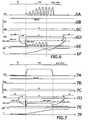
- FIG 7On the figure 7 are shown time diagrams of the simultaneous behaviors of the relevant quantities observed when a DC irradiation generator DC is used.
- the GEN generation profile of the DC generatoris represented on the Figure 7A .
- the reading FDD frequency of the photodiodeis fixed at 400 KHz and that, according to the embodiment corresponding to the figure 7 it is the electronic gain GAD which is modified to modify the resolution of the detection photodiode DD.
- the gain GADswitches in order to reduce the resolution of the detection photodiode DD and ensure a quantizing output signal NDD, as shown in FIG. figure 7E .
- the sum signal Sis here linear, of constant slope as represented on the figure 7F .
- stopping the generatorcauses the ACQ acquisition to stop by the acquisition diodes DA.
- the detection of the shutdown of the generatoris carried out by analysis of the signal NDD, as represented on the figure 7E .
- the shutdown of the DC generatoris here detected when the received energy decreases below a predetermined floor.
- the resolution modifications of the detection photodiode DDcan be realized, not only at the moment of switching to the acquisition mode of the acquisition diodes DA, but also during the ACQ acquisition by the diodes D. DA acquisition. This is useful when the generator is getting louder than expected.
- the FDD frequencyis increased, here multiplied by 4. Note, however, that this is not enough from the fourth pulse of the generator since the NDD signal reaches the voltage of 70% the supply voltage VAL. It is noted here that, nevertheless, the Diode DD does not saturate physically, the read signal SL remaining, moreover, quantifying the energy received by decreasing the reading frequency.
- the deviceis then able, thanks to the analysis of the instantaneous energy received by the analysis unit ANA, to further modify the resolution of the detection photodiode DD by further increasing the reading frequency of the detection photodiode DD here by multiplying it by 1.5 as soon as the NDD signal reaches 70% VAL.
- the NDD signalWith this new increase in the FDD read frequency, the NDD signal remains well below 70% of the supply voltage VAL.
- the output signal NDDthen remains in the energy interval read on the photodiode which can be amplified with the gain GAD without reaching the supply voltage VAL. This makes it possible to keep a quantification of the energy received which makes it possible to determine when the energy received corresponds to obtaining an image of correct quality.
Landscapes
- Physics & Mathematics (AREA)
- General Physics & Mathematics (AREA)
- Engineering & Computer Science (AREA)
- Multimedia (AREA)
- Signal Processing (AREA)
- General Health & Medical Sciences (AREA)
- Health & Medical Sciences (AREA)
- Toxicology (AREA)
- Transforming Light Signals Into Electric Signals (AREA)
- Measurement Of Radiation (AREA)
- Photometry And Measurement Of Optical Pulse Characteristics (AREA)
- Apparatus For Radiation Diagnosis (AREA)
- Solid State Image Pick-Up Elements (AREA)
- Studio Devices (AREA)
Description
Translated fromFrenchLa présente invention se rapporte au domaine général des capteurs d'acquisition d'images et de la commande de tels capteurs.The present invention relates to the general field of image acquisition sensors and the control of such sensors.
Plus précisément, l'invention concerne un dispositif d'acquisition d'images permettant d'obtenir une image radiologique dentaire, comprenant un capteur matriciel et un module de commande de ce capteur. L'invention s'intéresse aux dispositifs dans lesquels le capteur matriciel comprend une pluralité de photodiodes, dites d'acquisition d'images, sensibles à une irradiation, et au moins une photodiode dite de détection, également sensible à l'irradiation.More specifically, the invention relates to an image acquisition device for obtaining a dental radiological image, comprising a matrix sensor and a control module of this sensor. The invention is concerned with devices in which the matrix sensor comprises a plurality of photodiodes, called image acquisition, sensitive to irradiation, and at least one so-called detection photodiode, also sensitive to irradiation.
De tels capteurs existent, notamment en technologie CMOS qui autorise facilement l'intégration de photodiodes de caractéristiques géométriques différentes sur un même substrat. Il est en effet utile que la ou les photodiodes de détection présentent par exemple une taille différente de celle des photodiodes d'acquisition afin d'offrir une sensibilité plus élevée permettant la détection rapide d'un rayonnement.Such sensors exist, especially in CMOS technology that easily allows the integration of photodiodes of different geometric characteristics on the same substrate. It is indeed useful for the detection photodiodes to have, for example, a size different from that of the acquisition photodiodes in order to offer a higher sensitivity enabling the rapid detection of radiation.
Le dispositif selon l'invention comprend en outre un module de commande du capteur matriciel, apte à lire périodiquement la photodiode de détection et à basculer le capteur entre au moins deux modes : un mode d'attente dans lequel les photodiodes d'acquisition sont inhibées et un mode d'acquisition dans lequel l'énergie reçue par les photodiodes d'acquisition est utilisée pour l'acquisition d'une image.The device according to the invention further comprises a control module of the matrix sensor, able to periodically read the detection photodiode and to switch the sensor between at least two modes: a standby mode in which the acquisition photodiodes are inhibited and an acquisition mode in which the energy received by the acquisition photodiodes is used for acquiring an image.
Le terme « inhibition » s'entend comme signifiant que l'on ne charge pas les photons éventuellement reçus que ce soit par purge périodique des photodiodes d'acquisition ou par blocage de la réception des photons sur les photodiodes d'acquisition.The term "inhibition" is understood as meaning that the photons possibly received are not charged whether it is by periodic purge of the acquisition photodiodes or by blocking the reception of the photons on the acquisition photodiodes.
Dans les dispositifs connus, le basculement est déclenché dès lors que la photodiode de détection détecte une irradiation par un générateur. Généralement, la réception d'une quantité de lumière prédéterminée signifie la détection de l'irradiation.In known devices, the switchover is triggered as soon as the detection photodiode detects irradiation by a generator. Generally, receiving a predetermined amount of light means detecting the irradiation.
Les réalisations existantes permettent donc de déclencher l'acquisition d'image dès lors que la photodiode a reçu une quantité d'énergie donnée pendant la durée entre deux lectures de la photodiode de détection.The existing embodiments thus make it possible to trigger the image acquisition as soon as the photodiode has received a given quantity of energy during the time between two readings of the detection photodiode.
Avec les dispositifs connus, l'acquisition de l'image est généralement faite pendant toute la durée de l'irradiation ou durant une durée prédéterminée indépendamment de la quantité d'énergie qui est effectivement envoyée vers le capteur.With the known devices, image acquisition is generally done during the entire duration of the irradiation or for a predetermined duration regardless of the amount of energy that is actually sent to the sensor.
La présente invention a donc pour but principal de compléter les fonctions des dispositifs d'acquisition d'image par moyen d'un dispositif d'acquisition d'image selon la revendication indépendante 1, permettant d'obtenir une image radiologique dentaire selon la partie introductive de ladite revendication, en proposant qu'un tel dispositif soit tel que la photodiode de détection est apte à fournir au module de commande, y compris pendant l'irradiation et l'acquisition d'image par les photodiodes d'acquisition, un signal de sortie périodique de valeur représentative de l'énergie instantanée reçue et en ce que le module de commande utilise ce signal de sortie périodique pour analyser l'énergie reçue pendant l'acquisition.The present invention therefore has the main purpose of completing the functions of the image acquisition devices by means of an image acquisition device according to
Un tel capteur matriciel intégré permet de réaliser un suivi de l'énergie reçue par le capteur pendant l'acquisition de l'image puisque la diode est apte à fournir, y compris pendant l'acquisition, un signal représentatif de l'énergie reçue et donc quantitatif. On parlera, dans la suite, de signal quantifiant ou quantificateur.Such integrated matrix sensor makes it possible to monitor the energy received by the sensor during the acquisition of the image since the diode is able to supply, including during the acquisition, a signal representative of the energy received and therefore quantitative. In the following, we will speak of a quantizing or quantifying signal.
Avec un tel dispositif d'acquisition d'images, le module de commande est en connaissance de la quantité d'énergie reçue sur le capteur y compris pendant la période d'irradiation. La caractéristique selon laquelle la photodiode de détection est apte à fournir un signal périodique, la période de ce signal périodique étant définie par la période de lecture de la photodiode de détection, permet toute sorte d'implémentation de contrôle d'irradiation, jusque là non accessible avec les dispositifs connus.With such an image acquisition device, the control module is aware of the amount of energy received on the sensor including during the irradiation period. The characteristic according to which the detection photodiode is able to supply a periodic signal, the period of this periodic signal being defined by the reading period of the detection photodiode, allows any kind of implementation of irradiation control, until now no accessible with known devices.
L'invention permet en particulier de faire une analyse quantitative de l'énergie instantanée reçue en permanence. En suivant cette énergie reçue instantanée, il est possible de détecter des dysfonctionnements du générateur. Il est ainsi rendu possible selon l'invention de connaître la qualité du générateur sans faire appel à des appareils dédiés aptes à mesurer la quantité d'énergie effectivement émise.The invention makes it possible in particular to make a quantitative analysis of the instantaneous energy received continuously. By following this instantaneous received energy, it is possible to detect malfunctions of the generator. It is thus made possible according to the invention to know the quality of the generator without using dedicated devices able to measure the amount of energy actually emitted.
Ainsi, selon une caractéristique avantageuse, le module de commande est apte à insérer une courbe de suivi de l'énergie reçue dans une zone dédiée de l'image acquise.Thus, according to an advantageous characteristic, the control module is able to insert a curve for monitoring the energy received in a dedicated area of the acquired image.
Cette caractéristique permet, en analysant n'importe quelle image acquise avec un capteur selon l'invention sous l'irradiation d'un générateur particulier, d'extraire de cette image la courbe de suivi de l'énergie reçue. Cela permet d'évaluer la qualité d'émission du générateur en question puisqu'on dispose de sa courbe d'émission.This characteristic makes it possible, by analyzing any image acquired with a sensor according to the invention under the irradiation of a particular generator, to extract from this image the curve for monitoring the energy received. This makes it possible to evaluate the emission quality of the generator in question since it has its emission curve.
La zone dédiée où est insérée la courbe oscillogramme de l'énergie reçue est préférentiellement masquée dans l'image. Elle est soit prise sur l'image elle-même en constituant, par exemple la première ou la dernière ligne de l'image, ou encore être une ligne additionnelle dite zéro ajoutée à l'image.The dedicated zone where the oscillogram curve of the received energy is inserted is preferentially masked in the image. It is either taken on the image itself by constituting, for example the first or the last line of the image, or be an additional line called zero added to the image.
L'invention propose donc, selon cette caractéristique avantageuse, de condamner ainsi une très faible partie de l'image pour y insérer et mémoriser des données relatives aux caractéristiques du générateur puisque relatives à l'énergie reçue, et donc émise. Ainsi, lorsqu'une image de mauvaise qualité est obtenue, il est toujours possible, avec l'invention, de déterminer si la qualité dégradée est due à une émission dégradée du générateur ou s'il faut chercher d'autres raisons, par exemple un bougé du capteur pendant l'acquisition.The invention therefore proposes, according to this advantageous characteristic, to thus condemn a very small part of the image to insert and memorize data relating to the characteristics of the generator since relating to the energy received, and thus emitted. Thus, when an image of poor quality is obtained, it is always possible, with the invention, to determine whether the degraded quality is due to a degraded emission of the generator or whether to look for other reasons, for example a moving the sensor during acquisition.
On rappelle ici que le mode d'attente dans lequel les photodiodes d'acquisition sont inhibées signifie que l'on ne charge pas les photons grâce à une purge périodique ou grâce à un blocage à la réception des photons. Ainsi, dans le mode d'attente, on purge ou on bloque tant que la photodiode de détection n'a pas détecté l'irradiation. Cela permet d'obtenir un bon rapport signal sur bruit dans l'image finale. Sinon les lumières parasites reçues pendant le temps d'attente créeraient un phénomène de bruit de fond sur l'image qui nuirait à sa qualité.It is recalled here that the standby mode in which the acquisition photodiodes are inhibited means that the photons are not charged by means of a periodic purge or by blocking on reception of the photons. Thus, in the standby mode, one purges or blocks as long as the detection photodiode has not detected the irradiation. This makes it possible to obtain a good signal-to-noise ratio in the final image. Otherwise the parasitic lights received during the waiting time would create a phenomenon of background noise on the image that would affect its quality.
Il est par ailleurs nécessaire et connu que la photodiode de détection doit être plus grande que les photodiodes d'acquisition afin d'être suffisamment sensible pour détecter l'irradiation très rapidement quand on est en mode d'attente. Dans un tel cas, elle est alors très aisément sujette à saturation. Or, selon la caractéristique fonctionnelle de l'invention, la photodiode doit continuer de fournir un signal quantifiant y compris pendant l'acquisition.It is also necessary and known that the detection photodiode must be larger than the acquisition photodiodes in order to be sensitive enough to detect the irradiation very quickly when in standby mode. In such a case, it is then very easily subject to saturation. Gold, according to the functional characteristic of the invention, the photodiode must continue to provide a quantizing signal even during the acquisition.
Ainsi avantageusement, le module de commande est apte à modifier la résolution de la photodiode de détection, en fonction du signal de sortie de la photodiode de détection, afin d'assurer l'absence de saturation de la photodiode de détection lors de l'irradiation.Thus, advantageously, the control module is able to modify the resolution of the detection photodiode, as a function of the output signal of the detection photodiode, in order to ensure the absence of saturation of the detection photodiode during irradiation. .
Une telle modification de résolution est utile lorsque la sensibilité requise pour réaliser la détection de l'irradiation ne permet pas l'absence de saturation lors de l'irradiation.Such a modification of resolution is useful when the sensitivity required to achieve the detection of irradiation does not allow the absence of saturation during irradiation.
Cette caractéristique permet que la diode de détection présente une taille suffisante pour être assez sensible lors du mode d'attente et qu'elle soit néanmoins apte à fournir un signal quantitatif représentatif de l'énergie reçue tout au long de l'irradiation puisque c'est la fonction originale et nouvelle de l'invention.This characteristic makes it possible for the detection diode to be of sufficient size to be sensitive enough during the standby mode and that it nevertheless be able to provide a quantitative signal representative of the energy received throughout the irradiation since this is the original and novel function of the invention.
Cette caractéristique peut, selon l'invention, être mise en oeuvre de deux façons particulières agissant sur deux phénomènes de saturation distincts.This characteristic can, according to the invention, be implemented in two particular ways acting on two distinct saturation phenomena.
Le premier phénomène est le phénomène de saturation de la photodiode elle-même qui sature physiquement si elle reçoit une quantité d'énergie supérieure à une quantité d'énergie dite de saturation entre deux lectures. Si l'énergie reçue entre deux lectures est supérieure à la quantité d'énergie de saturation, le signal de lecture de la photodiode ne peut pas être quantitatif.The first phenomenon is the phenomenon of saturation of the photodiode itself which saturates physically if it receives a quantity of energy higher than a quantity of energy called saturation between two readings. If the energy received between two readings is greater than the amount of saturation energy, the reading signal of the photodiode can not be quantitative.
Ce signal de lecture de la photodiode est ensuite typiquement amplifié par un étage de traitement électronique avant d'être généralement échantillonné en le signal de sortie de la photodiode.This reading signal of the photodiode is then typically amplified by an electronic processing stage before being generally sampled in the output signal of the photodiode.
On comprend ici que l'on désigne par « signal de lecture de la photodiode », le signal tel que lu sur la photodiode et par « signal de sortie de la photodiode », le signal tel qu'obtenu après amplification.It is understood here that the term "read signal of the photodiode", the signal as read on the photodiode and "output signal of the photodiode", the signal as obtained after amplification.
Le second phénomène est le phénomène de saturation à cause de l'amplification du signal de lecture de la diode de détection. En effet, l'amplification ne peut pas produire un signal de sortie de la photodiode supérieur à la tension qui l'alimente. Si l'amplification d'un signal de lecture de la photodiode non saturée, et donc quantitatif, mène à un signal de sortie supérieur à cette tension d'alimentation, le signal de sortie n'est alors pas quantitatif.The second phenomenon is the saturation phenomenon because of the amplification of the reading signal of the detection diode. Indeed, the amplification can not produce an output signal of the photodiode greater than the voltage which supplies it. If the amplification of a reading signal of the unsaturated photodiode, and therefore quantitative, leads to an output signal greater than this supply voltage, the output signal is not quantitative.
Selon une caractéristique particulière de l'invention, pour modifier la résolution, le module de commande est apte à augmenter la fréquence de lecture de la photodiode de détection après détection de l'irradiation.According to a particular characteristic of the invention, in order to modify the resolution, the control module is able to increase the reading frequency of the detection photodiode after detection of the irradiation.
Dans ce cas, la capacité de traitement de l'énergie reçue de la photodiode est augmentée. En effet, en augmentant la fréquence de lecture, la photodiode de détection peut absorber plus d'énergie dans un même laps de temps et le phénomène de saturation peut alors ne pas être observé.In this case, the processing capacity of the energy received from the photodiode is increased. Indeed, by increasing the reading frequency, the detection photodiode can absorb more energy in the same period of time and the saturation phenomenon can then not be observed.
Dans les arts antérieurs connus, l'élément de détection ne quantifie pas le flux d'énergie reçue et il est donc égal que, pendant l'irradiation, cet élément de détection soit en saturation. C'est ce qui est d'ailleurs observé en pratique dans les arts antérieurs. Or cela est contraire à l'objet de l'invention, qui permet que la quantité d'énergie reçue soit connue par le module de commande en permanence et ce de manière quantitative.In the prior art known, the detection element does not quantify the energy flow received and it is therefore equal that, during irradiation, this detection element is in saturation. This is what is observed in practice in the earlier arts. However, this is contrary to the object of the invention, which allows the quantity of energy received to be known by the control module permanently and in a quantitative manner.
Augmenter la fréquence revient donc à diminuer la résolution de la photodiode puisque, pour une même puissance reçue, la lecture de la photodiode de détection interviendra pour des charges de la photodiode de détection moins importantes. Cela ne nuit néanmoins pas à la précision de la lecture pendant l'irradiation puisque des quantités importantes d'énergie sont reçues et que l'augmentation de fréquence permet précisément que les quantités lues soient représentatives de l'énergie réellement reçue.Increasing the frequency therefore amounts to decreasing the resolution of the photodiode since, for the same received power, the reading of the detection photodiode will occur for loads of the lower detection photodiode. This does not, however, affect the accuracy of reading during irradiation since large amounts of energy are received and the increase in frequency allows precisely that the quantities read are representative of the energy actually received.
Une augmentation de fréquence de lecture peut correspondre à multiplier celle-ci par dix, par exemple. Une telle augmentation de fréquence de lecture permet d'obtenir la saturation de la photodiode uniquement pour une énergie reçue dans un même laps de temps 10 fois plus importante qu'avec la fréquence initiale.An increase in reading frequency may correspond to multiplying it by ten, for example. Such an increase in reading frequency makes it possible to obtain the saturation of the photodiode only for an energy received in the same period of time 10 times greater than with the initial frequency.
Selon une autre caractéristique particulière de l'invention, chaque signal lu sur la photodiode de détection étant amplifié au sein d'une unité de traitement selon un gain dit électronique pour former le signal de sortie du capteur, le module de commande est apte à modifier ce gain électronique.According to another particular characteristic of the invention, each signal read on the detection photodiode being amplified within a processing unit according to a so-called electronic gain to form the output signal of the sensor, the control module is able to modify this electronic gain.
Cette caractéristique permet d'assurer que le signal de sortie reste quantifiant dès lors que la photodiode n'est pas, par ailleurs, saturée.This feature makes it possible to ensure that the output signal remains quantizing since the photodiode is not, moreover, saturated.
En effet, typiquement, le gain utilisé lors du mode d'attente est très élevé afin de pouvoir détecter l'irradiation le plus rapidement possible. S'il est conservé à cette valeur lors d'une irradiation, le signal de sortie de la photodiode qui est le signal de lecture amplifié dépassera vraisemblablement la tension d'alimentation de l'étage d'amplification et ne sera plus quantifiant et ce, même en présence d'une augmentation de fréquence de lecture de la photodiode de détection.Indeed, typically, the gain used during the standby mode is very high in order to detect the irradiation as quickly as possible. If it is kept at this value during irradiation, the output signal of the photodiode which is the amplified read signal will probably exceed the power supply voltage of the amplification stage and will no longer be quantifying, even in the presence of an increase in the reading frequency of the detection photodiode.
Cette caractéristique permet de résoudre le conflit entre la finesse de détection pendant le mode d'attente et la nécessité de rester quantifiant pendant le mode d'acquisition.This feature resolves the conflict between the detection fineness during the standby mode and the need to remain quantizing during the acquisition mode.
Avantageusement, la modification de gain aura donc lieu dès lors qu'une irradiation sera détectée. Dans le cas où la modification de fréquence de lecture est prévue pour être dépendante du niveau d'énergie reçue au début de l'irradiation, il sera avantageux que la modification du gain intervienne avant la modification de fréquence de lecture. Elle est donc avantageusement utilisée en complément et en combinaison avec la modification de la fréquence de lecture de la photodiode.Advantageously, the gain modification will therefore take place as soon as irradiation is detected. In the case where the read frequency change is intended to be dependent on the energy level received at the beginning of the irradiation, it will be advantageous for the change in gain to occur before the read frequency change. It is therefore advantageously used in addition and in combination with the modification of the reading frequency of the photodiode.
L'utilisation d'une photodiode de détection intégrée sur la même structure physique que les photodiodes d'acquisition de l'image, facilite la réalisation du contrôle de la fréquence de lecture ou de la modification du gain.The use of an integrated detection photodiode on the same physical structure as the image acquisition photodiodes, facilitates the realization of the control of the reading frequency or the modification of the gain.
Avantageusement, quatre niveaux de gain électronique sont prévus selon l'invention. Cette caractéristique offre quatre niveaux de résolution de la quantité d'énergie lue sur la photodiode et autorise l'obtention d'un signal de sortie quantificateur pour des quantités d'énergie lue très variées. En effet, les niveaux de gains extrémaux pourront être dédiés, l'un, le plus élevé, à la résolution des quantités d'énergie lues comprises entre 0 et 10 mV, l'autre, le plus faible, à la résolution des quantités d'énergie lues comprise entre 0 et 1000 mV.Advantageously, four levels of electronic gain are provided according to the invention. This characteristic offers four levels of resolution of the amount of energy read on the photodiode and allows obtaining a quantizer output signal for very varied amounts of energy read. In fact, the extremal gain levels can be dedicated, one, the highest, to the resolution of the quantities of energy read between 0 and 10 mV, the other, the lowest, to the resolution of the quantities of energy. energy read between 0 and 1000 mV.
Selon une autre caractéristique, le signal de sortie de la photodiode de détection est quantifié de manière continue entre deux valeurs analogiques.According to another characteristic, the output signal of the detection photodiode is quantized continuously between two analog values.
Cette caractéristique correspond à l'échantillonnage du signal de sortie qui est alors connu sous forme d'une valeur numérique permettant une connaissance fine de l'énergie reçue. Un tel échantillonnage est avantageusement réalisé sur 8 bits.This characteristic corresponds to the sampling of the output signal which is then known as a numerical value allowing a fine knowledge of the energy received. Such sampling is advantageously performed on 8 bits.
Dans une réalisation avantageuse, la photodiode de détection est intégrée sur la périphérie du capteur matriciel.In an advantageous embodiment, the detection photodiode is integrated on the periphery of the matrix sensor.
Cette caractéristique permet d'intégrer une photodiode rectangulaire de grande taille sur le contour des photodiodes d'acquisition qui sont, elles, intégrées sous forme d'une matrice. La technologie CMOS autorise une telle intégration.This feature makes it possible to integrate a large rectangular photodiode on the contour of the acquisition photodiodes which are themselves integrated in the form of a matrix. CMOS technology allows such integration.
Dans une application particulière, le module de commande est apte à arrêter le mode d'acquisition dès lors qu'une chute du signal de sortie de la photodiode de détection est observée.In a particular application, the control module is able to stop the acquisition mode as soon as a fall of the output signal of the detection photodiode is observed.
Cette caractéristique permet de contrôler l'acquisition d'images en fonction de l'énergie reçue. Cela permet d'obtenir des images de bonne qualité, en assurant qu'une énergie suffisante et optimale est reçue en assurant l'absence d'effet de saturation pénalisant sur les photodiodes d'acquisition. Dans le cas de l'utilisation d'un générateur AC, on entend par chute du signal de sortie, une absence de signal de sortie durant plus d'une période du générateur.En particulier, selon une caractéristique avantageuse, l'analyse de l'énergie reçue permet de calculer, pendant l'acquisition, la quantité d'énergie reçue par le capteur afin de la comparer avec une quantité d'énergie optimale à recevoir pour le capteur.This characteristic makes it possible to control the acquisition of images as a function of the energy received. This provides good quality images, ensuring that sufficient and optimal energy is received by ensuring the absence of saturation effect penalizing the acquisition photodiodes. In the case of the use of an AC generator, the term "drop of the output signal" means an absence of an output signal during more than one period of the generator. In particular, according to an advantageous characteristic, the analysis of the received energy makes it possible to calculate, during the acquisition, the quantity of energy received by the sensor in order to compare it with an optimal amount of energy to be received for the sensor.
Cette caractéristique permet de savoir à quel moment l'énergie reçue par le capteur correspond à l'énergie optimale pour l'obtention d'une image de bonne qualité. Cela pourra permettre d'arrêter le mode d'acquisition une fois cette énergie optimale atteinte et/ou une commande pourra être envoyée au générateur pour qu'il s'arrête.This characteristic makes it possible to know when the energy received by the sensor corresponds to the optimum energy for obtaining an image of good quality. This may make it possible to stop the acquisition mode once this optimum energy has been reached and / or a command can be sent to the generator so that it stops.
Ainsi, selon une caractéristique avantageuse de l'invention, le module de commande est apte à envoyer une commande à destination d'un générateur d'irradiation afin qu'il cesse l'irradiation dès lors que l'analyse de l'énergie reçue montre qu'une quantité d'énergie optimale à été reçue.Thus, according to an advantageous characteristic of the invention, the control module is able to send a command to an irradiation generator so that it stops irradiation when the analysis of the energy received shows an optimum amount of energy has been received.
Cette caractéristique avantageuse permet d'optimiser la quantité d'irradiation reçue par le patient puisque le générateur, lui-même, est arrêté dès lors qu'une quantité utile à l'obtention d'une image de qualité a été reçue sur le capteur.This advantageous characteristic makes it possible to optimize the amount of irradiation received by the patient since the generator, itself, is stopped as soon as a quantity useful for obtaining a quality image has been received on the sensor.
Avantageusement aussi, le module de commande est apte à arrêter le mode d'acquisition dès lors que l'analyse de l'énergie reçue montre que la quantité d'énergie énergie optimale a été reçue.Advantageously also, the control module is able to stop the acquisition mode as soon as the analysis of the received energy shows that the optimum amount of energy energy has been received.
L'invention concerne egalement un procédé de commande d'un dispositif d'acquisition d'image selon la revendication indépendante 9.The invention also relates to a method for controlling an image acquisition device according to independent claim 9.
Ce procédé assure un suivi de l'énergie reçue par le capteur matriciel avant l'irradiation et tout au long de l'irradiation.This method monitors the energy received by the matrix sensor before irradiation and throughout the irradiation.
Selon une implémentation préférée, les différentes étapes du procédé sont déterminées par des instructions de programmes d'ordinateur.According to a preferred implementation, the various steps of the method are determined by computer program instructions.
En conséquence, l'invention vise aussi une programme d'ordinateur selon la revendication indépendante 10, sur un support d'informations, ce programme étant susceptible d'être mis en oeuvre dans un module de commande et comportant des instructions adaptées à la mise en oeuvre des étapes du procédé selon l'invention. Ce programme peut utiliser n'importe quel langage de programmation et être sous la forme de codes-source, codes-objet ou de codes intermédiaires entre codes-source et codes-objet, tels que dans une forme partiellement compilée ou dans n'importe quelle autre forme souhaitable.Consequently, the invention also aims at a computer program according to independent claim 10, on an information medium, this program being able to be implemented in a control module and comprising instructions adapted to the implementation of steps of the method according to the invention. This program can use any programming language and be in the form of source codes, object codes, or intermediate codes between source codes and object codes, such as in a partially compiled form or in any other form. another desirable form.
L'invention vise aussi un support d'informations selon la revendication indépendante 11, lisible par un module de commande et comportant des instructions d'un programme d'ordinateur tel que mentionné ci-dessus. Le support d'informations peut être n'importe quel entité ou dispositif capable de stocker le programme. Le support peut être un élément matériel ou un support transmissible, pouvant être notamment téléchargé sur un réseau de type internet. Alternativement, le support d'informations peut être un circuit intégré dans lequel le programme est incorporé.The invention also relates to an information carrier according to independent claim 11, readable by a control module and comprising instructions of a computer program as mentioned above. The information carrier may be any entity or device capable of storing the program. The medium may be a hardware element or a transmissible medium, which may be notably downloaded on an Internet-type network. Alternatively, the information carrier may be an integrated circuit in which the program is embedded.
D'autres caractéristiques et avantages de la présente invention ressortiront de la description faite ci-dessous en référence aux figures annexées qui en illustrent un exemple de réalisation dépourvue de tout caractère limitatif, figures sur lesquelles :
- la
figure 1 représente schématiquement un capteur tel qu'utilisé dans un dispositif d'acquisition d'images selon l'invention; - la
figure 2 montre schématiquement la relation entre un module de commande, tel qu'implémenté dans un dispositif selon l'invention, et le capteur d'acquisition d'images; - la
figure 3 montre un organigramme d'un procédé selon l'invention ; - les
figures 4A à 4F montrent des diagrammes temporels des comportements simultanés respectivement d'un générateur d'irradiation à courant alternatif, d'une fréquence de lecture de la photodiode de détection dans un dispositif selon l'invention apte à modifier la résolution de la photodiode de détection par une augmentation de la fréquence de lecture de la photodiode de détection et à détecter l'arrêt du rayonnement, du gain de la photodiode, du gain électronique mis en oeuvre dans un module de commande du dispositif, du signal de sortie de la photodiode de détection et une lecture cumulée du signal de sortie ; - les
figures 5A à 5F montrent des diagrammes temporels des comportements simultanés respectivement d'un générateur d'irradiation à courant alternatif, d'une fréquence de lecture de la photodiode de détection dans un dispositif selon l'invention apte à modifier la résolution de la photodiode de détection par une augmentation de la fréquence de lecture de la photodiode de détection, à détecter qu'un seuil d'énergie reçue prédéterminé a été atteint et à inhiber l'acquisition d'image sur le capteur matriciel, du gain de la photodiode, du gain électronique mis en oeuvre dans un module de commande du dispositif, du signal de sortie de la photodiode de détection et une lecture cumulée du signal de sortie ; - les
figures 6A à 6F montrent des diagrammes temporels des comportements simultanés respectivement d'un générateur d'irradiation à courant alternatif, d'une fréquence de lecture de la photodiode de détection dans un dispositif selon l'invention apte à modifier la résolution de la photodiode en modifiant un gain électronique de traitement du signal de sortie de la photodiode de détection, à détecter qu'un seuil d'énergie reçue prédéterminé a été atteint et
- the
figure 1 schematically represents a sensor as used in an image acquisition device according to the invention; - the
figure 2 shows schematically the relation between a control module, as implemented in a device according to the invention, and the image acquisition sensor; - the
figure 3 shows a flowchart of a method according to the invention; - the
Figures 4A to 4F show temporal diagrams of the simultaneous behaviors respectively of an AC irradiation generator, a reading frequency of the detection photodiode in a device according to the invention capable of modifying the resolution of the detection photodiode by an increase of the reading frequency of the detection photodiode and detecting the radiation stop, the gain of the photodiode, the electronic gain implemented in a control module of the device, the output signal of the detection photodiode and a cumulative reading of the output signal; - the
Figures 5A to 5F show temporal diagrams of the simultaneous behaviors respectively of an AC irradiation generator, a reading frequency of the detection photodiode in a device according to the invention capable of modifying the resolution of the detection photodiode by an increase of the reading frequency of the detection photodiode, detecting that a predetermined received energy threshold has been reached and inhibiting the image acquisition on the matrix sensor, the gain of the photodiode, the electronic gain put in operating in a control module of the device, the output signal of the detection photodiode and a cumulative reading of the output signal; - the
Figures 6A to 6F show temporal diagrams of the simultaneous behaviors respectively of an AC irradiation generator, a reading frequency of the detection photodiode in a device according to the invention capable of modifying the resolution of the photodiode by modifying an electronic gain processing the output signal of the detection photodiode, detecting that a predetermined received energy threshold has been reached and
apte à inhiber l'acquisition d'image sur le capteur matriciel, du gain de la photodiode, du gain électronique mis en oeuvre dans un module de commande du dispositif, du signal de sortie de la photodiode de détection et une lecture cumulée du signal de sortie ;
- les
figures 7A à 7F montrent des diagrammes temporels des comportements simultanés respectivement d'un générateur d'irradiation à courant continu, d'une fréquence de lecture de la photodiode de détection dans un dispositif selon l'invention apte à modifier la résolution de la photodiode en modifiant un gain électronique de traitement du signal de sortie de la photodiode de détection, à détecter qu'un seuil d'énergie reçue prédéterminé a été atteint et apte à inhiber l'acquisition d'image sur le capteur matriciel, du gain de la photodiode, du gain électronique mis en oeuvre dans un module de commande du dispositif, du signal de sortie de la photodiode de détection et une lecture cumulée du signal de sortie ; - les
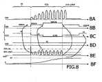
figures 8A à 8F montrent des diagrammes temporels des comportements simultanés respectivement d'un générateur d'irradiation à courant alternatif, d'une fréquence de lecture de la photodiode de détection dans un dispositif selon l'invention apte à modifier la résolution de la photodiode de détection par une augmentation de la fréquence de lecture de la photodiode de détection à tout moment de l'irradiation, à détecter qu'un seuil d'énergie reçue prédéterminé a été atteint et apte à inhiber l'acquisition d'image sur le capteur matriciel, du gain de la photodiode, du gain électronique mis en oeuvre dans un module de commande du dispositif, du signal de sortie de la photodiode de détection et une lecture cumulée du signal de sortie.
- the
Figures 7A to 7F show time diagrams of the simultaneous behaviors respectively of a DC irradiation generator, a reading frequency of the detection photodiode in a device according to the invention capable of modifying the resolution of the photodiode by modifying an electronic gain for processing the output signal of the detection photodiode, for detecting that a predetermined received energy threshold has been reached and able to inhibit the image acquisition on the matrix sensor, the gain of the photodiode, the electronic gain implemented in a control module of the device, the output signal of the detection photodiode and a cumulative reading of the output signal; - the
Figures 8A to 8F show temporal diagrams of the simultaneous behaviors respectively of an AC irradiation generator, a reading frequency of the detection photodiode in a device according to the invention capable of modifying the resolution of the detection photodiode by an increase of the reading frequency of the detection photodiode at any moment of the irradiation, detecting that a predetermined received energy threshold has been reached and able to inhibit the image acquisition on the matrix sensor, of the gain of the photodiode, the electronic gain implemented in a control module of the device, the output signal of the detection photodiode and a cumulative reading of the output signal.
La
Sur la périphérie des photodiodes d'acquisition DA est intégrée préférentiellement une unique photodiode de détection référencée DD.On the periphery of the acquisition photodiodes DA is preferably integrated a single detection photodiode referenced DD.
Dans une autre réalisation moins favorable, il pourrait être envisagé d'intégrer une pluralité de photodiodes de détection implémentées de manière à être lues périodiquement à la manière de l'invention. Néanmoins il est souhaitable que la taille des photodiodes de détection DD soit bien plus importante que la taille des photodiodes d'acquisition DA constituant le centre du capteur matriciel. En effet, on s'assure ainsi que la photodiode de détection sature plus rapidement et qu'elle a donc une sensibilité idoine pour la détection de l'irradiation. Il est donc préférable, pour une même surface utilisée, de n'intégrer qu'une unique diode de détection. Avantageusement une telle unique photodiode de détection DD sera intégrée sur la périphérie des photodiodes d'acquisition DA.In another less favorable embodiment, it could be envisaged to integrate a plurality of detection photodiodes implemented so as to be read periodically in the manner of the invention. Nevertheless, it is desirable that the size of the DD detection photodiodes be much larger than the size of the DA acquisition photodiodes constituting the center of the matrix sensor. Indeed, it is thus ensured that the detection photodiode saturates faster and therefore has a suitable sensitivity for the detection of irradiation. It is therefore preferable, for the same surface used, to integrate a single detection diode. Advantageously, such a single detection photodiode DD will be integrated on the periphery of the DA acquisition photodiodes.
Il va de soi qu'en variante, les photodiodes d'acquisition et/ou de détection peuvent être remplacées par tout type d'éléments photosensibles, comme des phototransistors par exemple.It goes without saying that, alternatively, the acquisition and / or detection photodiodes can be replaced by any type of photosensitive element, such as phototransistors for example.
Le capteur matriciel C est donc intégré de manière à pouvoir inclure ces deux types de diodes, par exemple en technologie CMOS. Il est sensible aux irradiations radiologiques au travers d'un scintillateur qui transforme la quantité d'énergie reçue sous forme de rayons X en une quantité de lumière.The matrix sensor C is therefore integrated so as to include these two types of diodes, for example in CMOS technology. It is sensitive to radiological irradiation through a scintillator that transforms the amount of energy received in the form of X-rays into a quantity of light.
L'énergie reçue sur la photodiode de détection DD est alors lue périodiquement selon la fréquence de lecture. Les données analogiques lues sur la photodiode constituent un signal de lecture de la photodiode SL. Des signaux de lecture SL périodiques sont ainsi obtenus lors des lectures successives de la photodiode de détection. Ils sont représentatifs de l'énergie reçue.The energy received on the detection photodiode DD is then read periodically according to the reading frequency. The analog data read on the photodiode is a read signal of the SL photodiode. Periodic SL read signals are thus obtained during successive readings of the detection photodiode. They are representative of the energy received.
Ainsi que représenté schématiquement sur la
L'unité de traitement analogique-numérique AD met en oeuvre un gain de traitement électronique, noté GAD, lors du transfert des données analogiques telles que lues sur la photodiode de détection DD vers une quantité numérique. L'unité AD réalise donc une amplification du signal de lecture en utilisant le gain GAD puis un échantillonnage de la valeur analogique amplifiée obtenue.The analog-digital processing unit AD implements an electronic processing gain, denoted GAD, during the transfer of the analog data as read on the detection photodiode DD to a digital quantity. The unit AD thus performs an amplification of the read signal using the GAD gain and then a sampling of the amplified analog value obtained.
Avantageusement, l'échantillonnage est tel que l'on obtient une valeur pour le signal de sortie NDD quasiment analogique entre deux valeurs extrémales, ce signal étant représentatif de l'énergie reçue sur le capteur.Advantageously, the sampling is such that one obtains a value for the almost analog NDD output signal between two extremal values, this signal being representative of the energy received on the sensor.
L'unité AD est avantageusement partie intégrante du capteur matriciel C ainsi que schématiquement représenté sur la
Ainsi que représenté sur la
La
Pour faciliter sa lecture, la
Ainsi, la lecture périodique de la diode de détection DD sous commande du module M est représentée par une étape E1, selon laquelle un signal de sortie NDD est obtenu à un instant Ti. La périodicité de cette lecture est illustrée schématiquement sur la
Lorsque le capteur matriciel C est en mode d'attente, le signal NDD est envoyé vers le module de commande M afin d'être utilisé dans une étape E0 dont l'objet est de détecter l'occurrence d'une irradiation.When the matrix sensor C is in standby mode, the signal NDD is sent to the control module M so as to be used in a step E0 whose object is to detect the occurrence of an irradiation.
Dans le cas où aucune irradiation n'est détectée (cas N : pas de saturation de la diode DD ou dépassement d'un seuil de détection ou observation d'une dynamique de montée d'énergie reçue), les diodes d'acquisition DA sont soumises à une commande d'inhibition, notée IDA sur la
Dans le cas où une irradiation est détectée dans l'étape E0 (cas O : saturation de la diode DD ou dépassement d'un seuil de détection ou observation d'une dynamique de montée d'énergie reçue), une étape E2 de basculement est déclenchée. Cette étape E2 a pour effet l'envoi d'une commande de basculement SBA du mode d'attente au mode d'acquisition ACQ vers les diodes d'acquisition DA.In the case where an irradiation is detected in the step E0 (case O: saturation of the diode DD or exceeding a detection threshold or observation of a received energy rise dynamic), a step E2 of switching is triggered. This step E2 has the effect of sending an SBA switching command from standby mode ACQ acquisition mode to DA acquisition diodes.
Cette étape E2 de basculement peut également générer une commande à destination de la diode de détection DD de manière à modifier sa résolution. En particulier, une commande FDD de modification de la fréquence de lecture de la photodiode de détection DD peut alors être envoyée. Avantageusement, et même de manière préalable à la commande de modification de fréquence de lecture FDD, une commande de modification du gain GAD de traitement électronique du signal de lecture SL de la photodiode de détection DD est aussi générée à ce moment-là.This step E2 of failover can also generate a command destined for the detection diode DD so as to modify its resolution. In particular, an FDD command for modifying the reading frequency of the detection photodiode DD can then be sent. Advantageously, and even before the FDD read frequency change control, a GAD gain control command for electronic processing of the read signal SL of the detection photodiode DD is also generated at this time.
Aussi, afin de déterminer la pertinence d'une commande de modification de résolution de la photodiode de détection DD, il est utile que la valeur du signal de sortie NDD soit aussi envoyé, en permanence, vers une unité d'analyse ANA du module de commande M, dans lequel la quantité d'énergie reçue et la dynamique de réception de l'énergie sont analysées au sein du module de commande M.Also, in order to determine the relevance of a resolution modification command of the detection photodiode DD, it is useful that the value of the output signal NDD is also sent, permanently, to an analysis unit ANA of the module. control M, in which the quantity of energy received and the energy reception dynamics are analyzed in the control module M.
L'unité ANA fonctionne ainsi avantageusement en permanence. Elle peut cependant aussi être activée seulement lors de l'étape E2. En fonction de la dynamique et de la quantité d'énergie reçue, cette unité ANA est apte à décider, et éventuellement à calculer, une modification de fréquence FDD de lecture de la diode de détection DD et/ou une modification du gain de traitement électronique GAD. Cette unité d'analyse ANA est également apte à déterminer si une quantité d'énergie optimale a été reçue ou encore, éventuellement, à déterminer une durée optimale pour l'acquisition de l'image en fonction de l'énergie reçue et de la dynamique de réception de cette énergie.The ANA unit thus operates advantageously continuously. However, it can also be activated only in step E2. As a function of the dynamics and the quantity of energy received, this unit ANA is able to decide, and possibly to calculate, a change in FDD frequency of reading of the detection diode DD and / or a modification of the electronic processing gain GAD. This analysis unit ANA is also able to determine whether an optimum amount of energy has been received or, possibly, to determine an optimal duration for the acquisition of the image as a function of the energy received and the dynamics receiving this energy.
Dans le mode de réalisation présenté sur la
Selon une caractéristique avantageuse, l'étape d'analyse ANA peut aussi mener à une étape E3', simultanée à l'étape E3 et représentée en traits pointillés, et qui engendre l'arrêt du générateur, noté GEN ici, qui irradie le capteur C dès lors qu'une quantité d'énergie optimale a été reçue. Cette étape E3' engendre l'envoi d'une commande d'arrêt STG du générateur GEN.According to an advantageous characteristic, the analysis step ANA can also lead to a step E3 ', simultaneous with the step E3 and represented in dashed lines, and which generates the stop of the generator, denoted GEN here, which irradiates the sensor C when an optimum amount of energy has been received. This step E3 'generates the sending of an STG stop command from the GEN generator.
Les
La
Selon l'invention, la photodiode de détection DD est lue périodiquement à une fréquence très supérieure à la fréquence des impulsions d'irradiation, ici à une fréquence FDD de 100 KHz ainsi que présenté sur la
Lorsque le générateur AC commence à émettre, le signal de sortie de la photodiode de détection NDD augmente fortement et rapidement, ainsi que représenté par un trait vertical élargi sur la
La détection du début de l'irradiation est donc réalisée sur un petit nombre d'échantillons de lecture de la photodiode de détection DD et n'est donc pas représentable sur les diagrammes temporels de la
Il existe divers modes de réalisation pour détecter l'occurrence de l'irradiation. Il est possible de considérer qu'une irradiation est détectée à partir du moment où le signal de sortie NDD pour au moins un échantillon de mesures dépasse une valeur seuil d'intensité d'énergie reçue. Le but étant de déclencher le plus rapidement possible, il est utile que le gain soit le plus important possible et la fréquence d'échantillonnage la plus faible possible en respectant les lois de l'échantillonnage. On remarque ici que la fréquence d'échantillonnage, même la plus faible possible reste, de toutes façons, très supérieure à la fréquence du rayonnement et permet donc, quoi qu'il en soit, une détection très rapide du rayonnement par rapport à la dynamique propre de ce rayonnement.There are various embodiments for detecting the occurrence of irradiation. It is possible to consider that irradiation is detected from the moment when the output signal NDD for at least one sample of measurements exceeds a threshold value of received energy intensity. The goal is to trigger as quickly as possible, it is useful that the gain is as large as possible and the sampling rate as low as possible by respecting the laws of sampling. It should be noted here that the sampling frequency, even the smallest possible, remains, in any case, much higher than the frequency of the radiation and therefore allows, in any case, a very fast detection of the radiation with respect to the dynamic clean of this radiation.
Il est également possible de ne détecter l'occurrence d'une irradiation qu'après avoir suivi un petit nombre d'échantillons de mesures du signal NDD, sur lesquels la dynamique de montée de l'énergie reçue a été analysée. La détection de l'irradiation est alors réalisée par un suivi de la dynamique de l'énergie reçue.It is also possible to detect the occurrence of an irradiation only after having followed a small number of samples of NDD signal measurements, on which the upward momentum of the received energy has been analyzed. The detection of the irradiation is then carried out by monitoring the dynamics of the energy received.
Cela permet d'utiliser la signature en montée d'irradiation du générateur pour déclencher le basculement vers le mode d'acquisition. Cette réalisation évite de déclencher le mode d'acquisition quand le capteur est irradié avec des énergies parasites autres que celle issue du scintillateur et correspondant aux rayons X émis par le générateur.This makes it possible to use the irradiation up sign of the generator to trigger the switchover to the acquisition mode. This embodiment avoids triggering the acquisition mode when the sensor is irradiated with parasitic energies other than that resulting from the scintillator and corresponding to the X-rays emitted by the generator.
Dès lors que l'émission par le générateur de rayons X a été détectée, conformément à la
En effet, la saturation de la photodiode de détection DD pendant l'acquisition d'une image empêcherait d'être quantitatif pour la mesure de l'énergie reçue et empêcherait donc de déterminer avec précision la limite d'exposition.Indeed, the saturation of the detection photodiode DD during the acquisition of an image would make it impossible to be quantitative for the measurement of the energy received and thus prevent the precise determination of the exposure limit.
Cette limite d'exposition est déterminée avantageusement grâce à un signal de somme des énergies reçues instantanées S. Ce signal représenté sur la
Sur la
La photodiode de détection DD est avantageusement utilisée pour détecter cet arrêt de l'émission du générateur. En effet, lorsque le signal NDD chute en dessous d'une valeur donnée pendant une durée supérieure à la demi-période d'émission du générateur, l'unité d'analyse ANA est avantageusement apte à générer une commande pour arrêter l'acquisition par les diodes d'acquisition DA.The detection photodiode DD is advantageously used to detect this stopping of the emission of the generator. Indeed, when the signal NDD drops below a given value for a duration greater than the half-period of emission of the generator, the analysis unit ANA is advantageously able to generate a command to stop the acquisition by the DA acquisition diodes.
On remarque ici que le gain de l'amplification électronique GAD n'est pas modifié par le module de commande M. Cela signifie que les signaux de lecture de la photodiode de détection amplifiés ne dépassent pas 70% de la tension d'alimentation VAL de l'unité d'amplification AD.It should be noted here that the gain of the electronic amplification GAD is not modified by the control module M. This means that the reading signals of the amplified detection photodiode do not exceed 70% of the supply voltage VAL of the amplification unit AD.
Suite à l'arrêt du rayonnement, avantageusement, l'unité d'analyse ANA est telle que, si une tension inférieure à 30% du seuil de saturation VSAT de la photodiode, la fréquence de lecture FDD est alors diminuée et le gain GAD est augmenté. Cette caractéristique permet de retourner aux conditions favorables à la détection d'un nouveau rayonnement par la photodiode de détection DD.Following the radiation stop, advantageously, the analysis unit ANA is such that, if a voltage less than 30% of the saturation threshold VSAT of the photodiode, the reading frequency FDD is then decreased and the gain GAD is increases. This characteristic makes it possible to return to the conditions favorable to the detection of a new radiation by the detection photodiode DD.
La
La différence avec la
Dans un mode de réalisation avantageux de l'invention non illustré ici, le module de commande M, commandant le capteur C, est apte à envoyer vers le générateur une commande pour que celui-ci arrête l'émission dès lors que le seuil optimal prédéterminé SPD a été atteint et que l'acquisition a été arrêtée.In an advantageous embodiment of the invention not illustrated here, the control module M, controlling the sensor C, is able to send to the generator a command so that the latter stops transmitting when the predetermined optimal threshold SPD was reached and the acquisition was stopped.
La
Ici, en mode d'attente, le gain GAD est multiplié par 4. Cela est utile pour augmenter la sensibilité de la détection. Ce gain GAD de 4 s'applique aussi à la tension de saturation VSAT de la photodiode de détection qui apparaît donc plus élevée sur le signal de sortie NDD. On remarque ainsi que les 70% VSAT ne sont pas représentés au début et à la fin de la
Sur la
En absence de la modification du gain GAD, la tension amplifiée NDD dépasserait la tension d'alimentation VAL et cela entrainerait la perte du caractère quantificateur du signal de sortie NDD.In the absence of the modification of the gain GAD, the amplified voltage NDD would exceed the supply voltage VAL and this would cause the loss of the quantizer character of the output signal NDD.
Pour que soit mise en oeuvre seulement la modification du gain électronique GAD, il est nécessaire que la photodiode ne sature pas à la fréquence utilisée. C'est pourquoi, sur cette figure, la fréquence utilisée est directement de 400 KHz, cette fréquence donnant la résolution la plus faible à la diode, y compris pendant le mode d'attente mais la plus grande capacité de réception d'énergie sans saturation.To implement only the modification of the electronic gain GAD, it is necessary that the photodiode does not saturate at the frequency used. Therefore, in this figure, the frequency used is directly 400 kHz, this frequency giving the lowest resolution to the diode, including during the standby mode but the largest capacity of energy reception without saturation .
Si la fréquence de la diode de détection DD était de 100 KHz, l'intensité reçue sur la photodiode de détection DD provoquerait la saturation de celle-ci. On observerait alors un écrêtage des impulsions observées sur la
En pratique, les modifications de gain d'amplification et de fréquence de lecture sont utilisées en combinaison. Le gain est avantageusement diminué dès la détection de l'irradiation, la fréquence étant subséquemment ou simultanément augmentée. Lorsque le module de commande M est tel que la modification de la fréquence de lecture est déterminé à chaque fois en fonction de l'énergie reçue, il est très utile que le gain soit de suite diminué de manière très importante, par exemple en passant de 1000 à 1, afin que la saturation de l'amplification électronique ne masque pas le signal quantificateur tel que lu sur la photodiode.In practice, the amplification gain and read frequency changes are used in combination. The gain is advantageously reduced as soon as the irradiation is detected, the frequency being subsequently or simultaneously increased. When the control module M is such that the modification of the reading frequency is determined in each case as a function of the energy received, it is very useful for the gain to be reduced in a very important way, for example by going from 1000 to 1, so that the saturation of the electronic amplification does not mask the quantizing signal as read on the photodiode.
En effet, il peut arriver qu'un gain important entraine qu'un signal quantificateur lu sur la photodiode non saturée, ne soit plus quantificateur après l'amplification car ayant atteint la tension d'alimentation VAL. Cela est dommageable quand justement le signal de sortie NDD, qui est le signal de lecture amplifié, est utilisé pour définir la fréquence de lecture FDD de la photodiode de détection DD. Il faudra en effet alors diminuer beaucoup plus cette fréquence FDD pour obtenir un signal quantificateur que si on diminue d'office, dès le début de l'irradiation, le gain d'amplification GAD. Cela est illustré dans la suite sur la
Sur la
Sur cette
Le signal somme S est ici linéaire, de pente constante ainsi que représenté sur la
Enfin, il faut remarquer que les modifications de résolution de la photodiode de détection DD peuvent être réalisées, non seulement au moment du basculement vers le mode d'acquisition des diodes d'acquisition DA, mais également pendant l'acquisition ACQ par les diodes d'acquisition DA. Cela est utile quand le générateur monte davantage en intensité qu'attendu.Finally, it should be noted that the resolution modifications of the detection photodiode DD can be realized, not only at the moment of switching to the acquisition mode of the acquisition diodes DA, but also during the ACQ acquisition by the diodes D. DA acquisition. This is useful when the generator is getting louder than expected.
Cela est représenté sur la
Dès que celle-ci est détectée, selon l'invention, la fréquence FDD est augmentée, ici multipliée par 4. On remarque, néanmoins, que cela ne suffit pas dès la quatrième impulsion du générateur puisque le signal NDD atteint la tension de 70% de la tension d'alimentation VAL. On note ici que, néanmoins, la diode DD ne sature pas physiquement, le signal de lecture SL restant, par ailleurs, quantificateur de l'énergie reçue grâce à la diminution de la fréquence de lecture.As soon as this is detected, according to the invention, the FDD frequency is increased, here multiplied by 4. Note, however, that this is not enough from the fourth pulse of the generator since the NDD signal reaches the voltage of 70% the supply voltage VAL. It is noted here that, nevertheless, the Diode DD does not saturate physically, the read signal SL remaining, moreover, quantifying the energy received by decreasing the reading frequency.
Le dispositif est alors apte, grâce à l'analyse de l'énergie instantanée reçue par l'unité d'analyse ANA, de modifier encore la résolution de la photodiode de détection DD en augmentant encore la fréquence de lecture de la photodiode de détection DD, ici en la multipliant par 1,5 dès que le signal NDD atteint 70% VAL.The device is then able, thanks to the analysis of the instantaneous energy received by the analysis unit ANA, to further modify the resolution of the detection photodiode DD by further increasing the reading frequency of the detection photodiode DD here by multiplying it by 1.5 as soon as the NDD signal reaches 70% VAL.
Avec cette nouvelle augmentation de la fréquence de lecture FDD, le signal NDD reste alors bien en-dessous de 70% de la tension d'alimentation VAL. Le signal de sortie NDD reste alors dans l'intervalle d'énergie lue sur la photodiode pouvant être amplifiée avec le gain GAD sans atteindre la tension d'alimentation VAL. Cela permet de conserver une quantification de l'énergie reçue qui permet de déterminer à quel moment l'énergie reçue correspond à l'obtention d'une image de qualité correcte.With this new increase in the FDD read frequency, the NDD signal remains well below 70% of the supply voltage VAL. The output signal NDD then remains in the energy interval read on the photodiode which can be amplified with the gain GAD without reaching the supply voltage VAL. This makes it possible to keep a quantification of the energy received which makes it possible to determine when the energy received corresponds to obtaining an image of correct quality.
Claims (11)
- An image acquisition device (C) enabling a dental radiological image to be obtained, the device comprising :a matrix sensor (C) integrating :a plurality of image acquisition photodiodes (DA) that are integrated in the form of a matrix and are sensitive to radiation; andat least one detection photodiode (DD) that is distinct from the image acquisition photodiodes, integrated at the periphery of the matrix of the matrix sensor, and likewise sensitive to radiation; anda control module (M) of the sensor (C) adapted to periodically read the detection photodiode (DD) and to cause the sensor (C) to switch between at least two modes: a standby mode in which the acquisition photodiodes are inhibited; and an acquisition mode (ACQ) in which the energy received by the acquisition photodiodes (DA) is used for the acquisition of an image; the switch being triggered (SBA) as soon as the detection photodiode (DD) detects radiation from a generator,characterized in that the detection photodiode (DD) is suitable for supplying a periodic output signal (NDD) to the control module (M), including during irradiation and image acquisition by the acquisition photodiodes (DA), the periodic output signal (NDD) having a value that is representative of the instantaneous received energy, andin that the control module (M) uses this periodic output signal (NDD) to analyze (ANA) the energy received during acquisition (ACQ), the control module (M) being further suitable for modifying the resolution of the detection photodiode (DD) as a function of the output signal (NDD) of the detection photodiode (DD), in order to ensure that the detection photodiode (DD) does not saturate during the irradiation.
- A device according to claim 1,characterized in that the control module (M) is suitable for inserting, in a dedicated zone of the acquired image, a curve tracking the quantity of energy received (S).
- A device according to one of claims 1 and 2,characterized in that, to modify the resolution, the control module (M) is suitable for increasing the read frequency (NDD) of the detection photodiode (DD) after radiation has been detected.
- A device according to one of claims 1 to 3,characterized in that each signal read from the detection photodiode (DD) is amplified within a processing unit (AD) by an electronic gain (GAD) to form the output signal (NDD) from the sensor (C), the control module (M) being suitable for modifying this electronic gain (GAD).
- A device according to one of claims 1 to 4,characterized in that the control module (M) is suitable for stopping the acquisition mode (ACQ) as soon as a drop is observed in the output signal (NDD) from the detection photodiode (DD).
- A device according to one of claims 1 to 5,characterized in that the analysis (ANA) of the received energy makes it possible, during the acquisition (ACQ), to calculate the quantity of energy received (S) by the sensor (C) so as to compare it with an optimum quantity (SPD) of energy to be received by the sensor (C).
- A device according to claim 6,characterized in that the control module (M) is suitable for sending a command (STG) to an irradiation generator (GEN) so that it stops irradiating as soon as the analysis (ANA) of the received energy (S) shows that the optimum quantity (SPD) of energy has been received.
- A device according to one of claims 6 and 7,characterized in that the control module (M) is suitable for stopping the acquisition mode (ACQ) as soon as the analysis (ANA) of the received energy shows that the optimum quantity (SPD) of energy has been received.
- A method of controlling an image acquisition device according to one of claims 1 to 8, comprising the steps of:- periodic sending (E1) of read commands of the detection photodiode (DD) before and during irradiation and image acquisition (ACQ) by the acquisition photodiodes (DA), and- providing, by the detection photodiode, a periodic output signal (NDD) of a value that is representative of the instantaneous received energy, and- receiving the output signal (NDD), and- commanding (E2) the sensor (C) to switch (SBA) between the standby mode and the acquisition mode (ACQ), the switch being triggered when the detection photodiode detects (E0) irradiation from a generator (GEN), and- analyzing (ANA) the energy received during acquisition by using the periodic output signal (NDD), and- modifying, by the control module (M), the resolution of the detection photodiode (DD) as a function of the output signal (NDD) of the detection photodiode (DD), in order to ensure that the detection photodiode (DD) does not saturate during the irradiation.
- A computer program including instructions for executing steps of the control method of claim 9 when said program is executed by a control module (M) as well as implemented in an image acquisition device according to any one of claims 1 to 8.
- A computer-readable recording medium having recorded thereon a computer program including instructions for executing steps of the control method according to claim 9.
Priority Applications (1)
| Application Number | Priority Date | Filing Date | Title |
|---|---|---|---|
| PL09760546TPL2359188T3 (en) | 2008-11-25 | 2009-10-28 | Multifunctional device for acquiring images |
Applications Claiming Priority (2)
| Application Number | Priority Date | Filing Date | Title |
|---|---|---|---|
| FR0858011AFR2938936B1 (en) | 2008-11-25 | 2008-11-25 | MULTIFUNCTION IMAGE ACQUISITION DEVICE |
| PCT/FR2009/052080WO2010061086A1 (en) | 2008-11-25 | 2009-10-28 | Multifunctional image acquisition device |
Publications (2)
| Publication Number | Publication Date |
|---|---|
| EP2359188A1 EP2359188A1 (en) | 2011-08-24 |
| EP2359188B1true EP2359188B1 (en) | 2015-01-21 |
Family
ID=40671143
Family Applications (1)
| Application Number | Title | Priority Date | Filing Date |
|---|---|---|---|
| EP09760546.3AActiveEP2359188B1 (en) | 2008-11-25 | 2009-10-28 | Multifunctional image acquisition device |
Country Status (15)
| Country | Link |
|---|---|
| US (1) | US8637829B2 (en) |
| EP (1) | EP2359188B1 (en) |
| JP (1) | JP5715960B2 (en) |
| KR (1) | KR101597323B1 (en) |
| CN (1) | CN102224457B (en) |
| AU (1) | AU2009321433B2 (en) |
| BR (1) | BRPI0920900B1 (en) |
| DK (1) | DK2359188T3 (en) |
| ES (1) | ES2534932T3 (en) |
| FR (1) | FR2938936B1 (en) |
| IL (1) | IL212408B (en) |
| PL (1) | PL2359188T3 (en) |
| RU (1) | RU2514149C2 (en) |
| TW (1) | TWI467314B (en) |
| WO (1) | WO2010061086A1 (en) |
Families Citing this family (8)
| Publication number | Priority date | Publication date | Assignee | Title |
|---|---|---|---|---|
| US9301569B2 (en) | 2010-06-22 | 2016-04-05 | Nike, Inc. | Article of footwear with color change portion and method of changing color |
| US8474146B2 (en) | 2010-06-22 | 2013-07-02 | Nike, Inc. | Article of footwear with color change portion and method of changing color |
| JP5745085B2 (en)* | 2011-11-01 | 2015-07-08 | 富士フイルム株式会社 | Radiographic apparatus, radiographic system, and radiographic method |
| JP6272046B2 (en)* | 2014-01-22 | 2018-01-31 | キヤノン株式会社 | Radiation imaging apparatus, control method therefor, and radiation inspection apparatus |
| US9993221B2 (en) | 2014-11-19 | 2018-06-12 | Samsung Electronics Co., Ltd. | X-ray apparatus and system |
| JP6039782B2 (en)* | 2015-11-18 | 2016-12-07 | 富士フイルム株式会社 | Radiation image detection apparatus and irradiation detection method used for radiation image detection apparatus |
| JP7266052B2 (en)* | 2021-02-12 | 2023-04-27 | 浜松ホトニクス株式会社 | Intraoral imaging system and imaging device |
| JP7744139B2 (en) | 2021-02-15 | 2025-09-25 | 浜松ホトニクス株式会社 | Intraoral imaging device |
Family Cites Families (23)
| Publication number | Priority date | Publication date | Assignee | Title |
|---|---|---|---|---|
| JP2890553B2 (en)* | 1989-11-24 | 1999-05-17 | 株式会社島津製作所 | X-ray imaging device |
| SE469104B (en)* | 1991-06-03 | 1993-05-10 | Regam Medical Systems Ab | PROCEDURE AND DEVICE FOR X-ray apparatus with electronic image detection |
| JPH05130990A (en)* | 1991-10-25 | 1993-05-28 | Hamamatsu Photonics Kk | Medical X-ray image detector with automatic exposure function |
| DE4235527C2 (en)* | 1991-10-25 | 1998-07-09 | Morita Mfg | Device for the acquisition of medical X-ray images with automatic exposure |
| GB2289983B (en)* | 1994-06-01 | 1996-10-16 | Simage Oy | Imaging devices,systems and methods |
| US5510623A (en)* | 1995-02-24 | 1996-04-23 | Loral Fairchild Corp. | Center readout intra-oral image sensor |
| FR2750821B1 (en)* | 1996-07-05 | 1998-09-11 | Commissariat Energie Atomique | METHOD AND DEVICE FOR TAKING DIGITAL IMAGES WITH CONTROL AND OPTIMIZATION OF THE TIME OF EXPOSURE OF THE OBJECT TO X OR Y RADIATION |
| US5887049A (en)* | 1996-11-12 | 1999-03-23 | California Institute Of Technology | Self-triggered X-ray sensor |
| JPH11188033A (en)* | 1997-12-26 | 1999-07-13 | Hamamatsu Photonics Kk | Dental X-ray image capturing apparatus and module for dental X-ray image capturing apparatus |
| JP2001299734A (en)* | 2000-04-27 | 2001-10-30 | Matsushita Electric Ind Co Ltd | X-ray equipment |
| US6404854B1 (en)* | 2000-06-26 | 2002-06-11 | Afp Imaging Corporation | Dental x-ray imaging system |
| JP4004761B2 (en)* | 2001-01-18 | 2007-11-07 | シャープ株式会社 | Flat panel image sensor |
| JP4217506B2 (en)* | 2002-03-01 | 2009-02-04 | キヤノン株式会社 | Radiation imaging device |
| JP4164282B2 (en)* | 2002-04-16 | 2008-10-15 | キヤノン株式会社 | Radiation imaging apparatus, radiation imaging method, and computer program |
| JP2004023654A (en)* | 2002-06-19 | 2004-01-22 | Canon Inc | Radiation imaging apparatus and radiation imaging method |
| FR2842300A1 (en) | 2002-07-11 | 2004-01-16 | Sopro | METHOD AND DEVICE FOR SELECTING THE SHADE OF A DENTAL TEEN |
| JP4501383B2 (en)* | 2003-09-12 | 2010-07-14 | パナソニック株式会社 | X-ray equipment |
| TWI239829B (en)* | 2003-09-26 | 2005-09-21 | Ebm Technologies Inc | Method for manufacturing guiding device for surgical operation with tomography and reverse engineering |
| DE60334915D1 (en)* | 2003-11-26 | 2010-12-23 | Carestream Health Inc | Method for signal processing in a dental radiology device |
| US7006600B1 (en)* | 2004-01-15 | 2006-02-28 | Progeny, Inc. | Integrated digital dental x-ray system |
| JP4536556B2 (en)* | 2005-03-08 | 2010-09-01 | 浜松ホトニクス株式会社 | X-ray imaging device |
| GB0517741D0 (en)* | 2005-08-31 | 2005-10-12 | E2V Tech Uk Ltd | Image sensor |
| JP4800045B2 (en)* | 2006-01-30 | 2011-10-26 | 浜松ホトニクス株式会社 | Solid-state imaging device |
- 2008
- 2008-11-25FRFR0858011Apatent/FR2938936B1/enactiveActive
- 2009
- 2009-10-28CNCN200980147254.3Apatent/CN102224457B/enactiveActive
- 2009-10-28JPJP2011536922Apatent/JP5715960B2/enactiveActive
- 2009-10-28EPEP09760546.3Apatent/EP2359188B1/enactiveActive
- 2009-10-28WOPCT/FR2009/052080patent/WO2010061086A1/enactiveApplication Filing
- 2009-10-28BRBRPI0920900Apatent/BRPI0920900B1/enactiveIP Right Grant
- 2009-10-28USUS13/129,461patent/US8637829B2/enactiveActive
- 2009-10-28RURU2011123698/28Apatent/RU2514149C2/enactive
- 2009-10-28KRKR1020117011849Apatent/KR101597323B1/enactiveActive
- 2009-10-28PLPL09760546Tpatent/PL2359188T3/enunknown
- 2009-10-28ESES09760546.3Tpatent/ES2534932T3/enactiveActive
- 2009-10-28AUAU2009321433Apatent/AU2009321433B2/enactiveActive
- 2009-10-28DKDK09760546Tpatent/DK2359188T3/enactive
- 2009-11-23TWTW98139762Apatent/TWI467314B/enactive
- 2011
- 2011-04-17ILIL212408Apatent/IL212408B/enactiveIP Right Grant
Also Published As
| Publication number | Publication date |
|---|---|
| TW201102750A (en) | 2011-01-16 |
| CN102224457A (en) | 2011-10-19 |
| US20110233416A1 (en) | 2011-09-29 |
| AU2009321433A1 (en) | 2010-06-03 |
| KR20110091518A (en) | 2011-08-11 |
| US8637829B2 (en) | 2014-01-28 |
| DK2359188T3 (en) | 2015-04-20 |
| JP5715960B2 (en) | 2015-05-13 |
| TWI467314B (en) | 2015-01-01 |
| RU2011123698A (en) | 2013-01-10 |
| RU2514149C2 (en) | 2014-04-27 |
| JP2012509696A (en) | 2012-04-26 |
| IL212408B (en) | 2019-02-28 |
| WO2010061086A1 (en) | 2010-06-03 |
| CN102224457B (en) | 2014-07-23 |
| AU2009321433B2 (en) | 2014-05-29 |
| FR2938936B1 (en) | 2016-01-15 |
| IL212408A0 (en) | 2011-06-30 |
| ES2534932T3 (en) | 2015-04-30 |
| BRPI0920900A2 (en) | 2015-12-29 |
| BRPI0920900B1 (en) | 2020-05-19 |
| PL2359188T3 (en) | 2015-06-30 |
| KR101597323B1 (en) | 2016-02-24 |
| HK1161756A1 (en) | 2012-08-03 |
| EP2359188A1 (en) | 2011-08-24 |
| FR2938936A1 (en) | 2010-05-28 |
Similar Documents
| Publication | Publication Date | Title |
|---|---|---|
| EP2359188B1 (en) | Multifunctional image acquisition device | |
| EP1704422B1 (en) | Radiation detecting system with double resetting pulse count | |
| EP2484011B1 (en) | Device for the processing of a signal generated by a radiation detector | |
| EP2356810B1 (en) | Imaging device with double charge transfer for high dynamic range and the corresponding driving method | |
| FR2837053A1 (en) | BI OR MULTI-ENERGY IMAGING METHOD AND SYSTEM | |
| FR2973162A1 (en) | VERY HIGH DYNAMIC IMAGE SENSOR | |
| EP2732617B1 (en) | Method for controlling a photoelectric detector by automatically detecting the incoming light | |
| EP2541280A2 (en) | Device for detecting ionising radiation with semiconductor detector with improved spectrometric response | |
| EP2383980A1 (en) | CMOS Image sensor having a wide linear dynamic range | |
| FR3025086A1 (en) | METHOD AND SYSTEM FOR TAKING MEDICAL RADIOLOGICAL IMAGES WITH STOP CONTROL OF THE X-RAY SOURCE | |
| FR2914463A1 (en) | METHOD FOR CORRECTING REMANENT LOADS IN AN X-RAY FLAT PANEL DETECTOR | |
| FR2847676A1 (en) | Spectrometry chain processing circuit, has differentiator stage that receives signal from pre-amplifier stage and delivers image signal of detector current to integrator stage, which delivers image of quantity of charge emitted by particle | |
| JP5027932B2 (en) | Active pixel sensor device used for star lacquer device | |
| WO2009068526A1 (en) | Image sensor having four-transistor or five-transistor pixels with reset noise reduction | |
| EP1402285B1 (en) | Device for reducing the lag and the dark current in a particle detector, in particular a photon detector | |
| EP3984461B1 (en) | Method for monitoring the real-time exposure of a dose of x-rays | |
| US11606549B1 (en) | Methods and systems for mitigating persistence in photodetectors | |
| EP1573362B1 (en) | Device for correcting a signal derived from a detector | |
| WO2005022898A1 (en) | Wide-dynamic-range radiation detector | |
| EP3123462A1 (en) | Display control method and device for implementing said method | |
| HK1161756B (en) | Multifunctional image acquisition device |
Legal Events
| Date | Code | Title | Description |
|---|---|---|---|
| PUAI | Public reference made under article 153(3) epc to a published international application that has entered the european phase | Free format text:ORIGINAL CODE: 0009012 | |
| 17P | Request for examination filed | Effective date:20110406 | |
| AK | Designated contracting states | Kind code of ref document:A1 Designated state(s):AT BE BG CH CY CZ DE DK EE ES FI FR GB GR HR HU IE IS IT LI LT LU LV MC MK MT NL NO PL PT RO SE SI SK SM TR | |
| DAX | Request for extension of the european patent (deleted) | ||
| 17Q | First examination report despatched | Effective date:20120726 | |
| GRAP | Despatch of communication of intention to grant a patent | Free format text:ORIGINAL CODE: EPIDOSNIGR1 | |
| INTG | Intention to grant announced | Effective date:20140305 | |
| GRAP | Despatch of communication of intention to grant a patent | Free format text:ORIGINAL CODE: EPIDOSNIGR1 | |
| INTG | Intention to grant announced | Effective date:20140617 | |
| GRAP | Despatch of communication of intention to grant a patent | Free format text:ORIGINAL CODE: EPIDOSNIGR1 | |
| GRAS | Grant fee paid | Free format text:ORIGINAL CODE: EPIDOSNIGR3 | |
| INTG | Intention to grant announced | Effective date:20141119 | |
| GRAA | (expected) grant | Free format text:ORIGINAL CODE: 0009210 | |
| AK | Designated contracting states | Kind code of ref document:B1 Designated state(s):AT BE BG CH CY CZ DE DK EE ES FI FR GB GR HR HU IE IS IT LI LT LU LV MC MK MT NL NO PL PT RO SE SI SK SM TR | |
| REG | Reference to a national code | Ref country code:GB Ref legal event code:FG4D Free format text:NOT ENGLISH | |
| REG | Reference to a national code | Ref country code:CH Ref legal event code:EP | |
| REG | Reference to a national code | Ref country code:IE Ref legal event code:FG4D Free format text:LANGUAGE OF EP DOCUMENT: FRENCH | |
| REG | Reference to a national code | Ref country code:DE Ref legal event code:R096 Ref document number:602009029112 Country of ref document:DE Effective date:20150305 | |
| REG | Reference to a national code | Ref country code:AT Ref legal event code:REF Ref document number:709441 Country of ref document:AT Kind code of ref document:T Effective date:20150315 | |
| REG | Reference to a national code | Ref country code:DK Ref legal event code:T3 Effective date:20150417 | |
| REG | Reference to a national code | Ref country code:SE Ref legal event code:TRGR | |
| REG | Reference to a national code | Ref country code:ES Ref legal event code:FG2A Ref document number:2534932 Country of ref document:ES Kind code of ref document:T3 Effective date:20150430 Ref country code:CH Ref legal event code:NV Representative=s name:BOVARD AG, CH | |
| REG | Reference to a national code | Ref country code:LT Ref legal event code:MG4D | |
| REG | Reference to a national code | Ref country code:PL Ref legal event code:T3 | |
| PG25 | Lapsed in a contracting state [announced via postgrant information from national office to epo] | Ref country code:BG Free format text:LAPSE BECAUSE OF FAILURE TO SUBMIT A TRANSLATION OF THE DESCRIPTION OR TO PAY THE FEE WITHIN THE PRESCRIBED TIME-LIMIT Effective date:20150421 Ref country code:HR Free format text:LAPSE BECAUSE OF FAILURE TO SUBMIT A TRANSLATION OF THE DESCRIPTION OR TO PAY THE FEE WITHIN THE PRESCRIBED TIME-LIMIT Effective date:20150121 Ref country code:LT Free format text:LAPSE BECAUSE OF FAILURE TO SUBMIT A TRANSLATION OF THE DESCRIPTION OR TO PAY THE FEE WITHIN THE PRESCRIBED TIME-LIMIT Effective date:20150121 Ref country code:NO Free format text:LAPSE BECAUSE OF FAILURE TO SUBMIT A TRANSLATION OF THE DESCRIPTION OR TO PAY THE FEE WITHIN THE PRESCRIBED TIME-LIMIT Effective date:20150421 | |
| PG25 | Lapsed in a contracting state [announced via postgrant information from national office to epo] | Ref country code:IS Free format text:LAPSE BECAUSE OF FAILURE TO SUBMIT A TRANSLATION OF THE DESCRIPTION OR TO PAY THE FEE WITHIN THE PRESCRIBED TIME-LIMIT Effective date:20150521 Ref country code:LV Free format text:LAPSE BECAUSE OF FAILURE TO SUBMIT A TRANSLATION OF THE DESCRIPTION OR TO PAY THE FEE WITHIN THE PRESCRIBED TIME-LIMIT Effective date:20150121 Ref country code:GR Free format text:LAPSE BECAUSE OF FAILURE TO SUBMIT A TRANSLATION OF THE DESCRIPTION OR TO PAY THE FEE WITHIN THE PRESCRIBED TIME-LIMIT Effective date:20150422 | |
| REG | Reference to a national code | Ref country code:SK Ref legal event code:T3 Ref document number:E 18882 Country of ref document:SK | |
| REG | Reference to a national code | Ref country code:DE Ref legal event code:R097 Ref document number:602009029112 Country of ref document:DE | |
| REG | Reference to a national code | Ref country code:FR Ref legal event code:PLFP Year of fee payment:7 | |
| PG25 | Lapsed in a contracting state [announced via postgrant information from national office to epo] | Ref country code:CZ Free format text:LAPSE BECAUSE OF FAILURE TO SUBMIT A TRANSLATION OF THE DESCRIPTION OR TO PAY THE FEE WITHIN THE PRESCRIBED TIME-LIMIT Effective date:20150121 Ref country code:EE Free format text:LAPSE BECAUSE OF FAILURE TO SUBMIT A TRANSLATION OF THE DESCRIPTION OR TO PAY THE FEE WITHIN THE PRESCRIBED TIME-LIMIT Effective date:20150121 Ref country code:RO Free format text:LAPSE BECAUSE OF FAILURE TO SUBMIT A TRANSLATION OF THE DESCRIPTION OR TO PAY THE FEE WITHIN THE PRESCRIBED TIME-LIMIT Effective date:20150121 | |
| PLBE | No opposition filed within time limit | Free format text:ORIGINAL CODE: 0009261 | |
| STAA | Information on the status of an ep patent application or granted ep patent | Free format text:STATUS: NO OPPOSITION FILED WITHIN TIME LIMIT | |
| 26N | No opposition filed | Effective date:20151022 | |
| PG25 | Lapsed in a contracting state [announced via postgrant information from national office to epo] | Ref country code:SI Free format text:LAPSE BECAUSE OF FAILURE TO SUBMIT A TRANSLATION OF THE DESCRIPTION OR TO PAY THE FEE WITHIN THE PRESCRIBED TIME-LIMIT Effective date:20150121 | |
| REG | Reference to a national code | Ref country code:AT Ref legal event code:UEP Ref document number:709441 Country of ref document:AT Kind code of ref document:T Effective date:20150121 | |
| PG25 | Lapsed in a contracting state [announced via postgrant information from national office to epo] | Ref country code:MC Free format text:LAPSE BECAUSE OF FAILURE TO SUBMIT A TRANSLATION OF THE DESCRIPTION OR TO PAY THE FEE WITHIN THE PRESCRIBED TIME-LIMIT Effective date:20150121 | |
| REG | Reference to a national code | Ref country code:IE Ref legal event code:MM4A | |
| REG | Reference to a national code | Ref country code:FR Ref legal event code:PLFP Year of fee payment:8 | |
| PG25 | Lapsed in a contracting state [announced via postgrant information from national office to epo] | Ref country code:IE Free format text:LAPSE BECAUSE OF NON-PAYMENT OF DUE FEES Effective date:20151028 | |
| PG25 | Lapsed in a contracting state [announced via postgrant information from national office to epo] | Ref country code:HU Free format text:LAPSE BECAUSE OF FAILURE TO SUBMIT A TRANSLATION OF THE DESCRIPTION OR TO PAY THE FEE WITHIN THE PRESCRIBED TIME-LIMIT; INVALID AB INITIO Effective date:20091028 Ref country code:SM Free format text:LAPSE BECAUSE OF FAILURE TO SUBMIT A TRANSLATION OF THE DESCRIPTION OR TO PAY THE FEE WITHIN THE PRESCRIBED TIME-LIMIT Effective date:20150121 | |
| PG25 | Lapsed in a contracting state [announced via postgrant information from national office to epo] | Ref country code:CY Free format text:LAPSE BECAUSE OF FAILURE TO SUBMIT A TRANSLATION OF THE DESCRIPTION OR TO PAY THE FEE WITHIN THE PRESCRIBED TIME-LIMIT Effective date:20150121 | |
| PG25 | Lapsed in a contracting state [announced via postgrant information from national office to epo] | Ref country code:MT Free format text:LAPSE BECAUSE OF FAILURE TO SUBMIT A TRANSLATION OF THE DESCRIPTION OR TO PAY THE FEE WITHIN THE PRESCRIBED TIME-LIMIT Effective date:20150121 | |
| REG | Reference to a national code | Ref country code:FR Ref legal event code:PLFP Year of fee payment:9 | |
| PG25 | Lapsed in a contracting state [announced via postgrant information from national office to epo] | Ref country code:PT Free format text:LAPSE BECAUSE OF FAILURE TO SUBMIT A TRANSLATION OF THE DESCRIPTION OR TO PAY THE FEE WITHIN THE PRESCRIBED TIME-LIMIT Effective date:20150121 Ref country code:MK Free format text:LAPSE BECAUSE OF FAILURE TO SUBMIT A TRANSLATION OF THE DESCRIPTION OR TO PAY THE FEE WITHIN THE PRESCRIBED TIME-LIMIT Effective date:20150121 | |
| REG | Reference to a national code | Ref country code:FR Ref legal event code:PLFP Year of fee payment:10 | |
| REG | Reference to a national code | Ref country code:DE Ref legal event code:R082 Ref document number:602009029112 Country of ref document:DE Representative=s name:CBDL PATENTANWAELTE GBR, DE Ref country code:DE Ref legal event code:R082 Ref document number:602009029112 Country of ref document:DE Representative=s name:CBDL PATENTANWAELTE EGBR, DE | |
| PGFP | Annual fee paid to national office [announced via postgrant information from national office to epo] | Ref country code:DK Payment date:20240925 Year of fee payment:16 | |
| PGFP | Annual fee paid to national office [announced via postgrant information from national office to epo] | Ref country code:LU Payment date:20240925 Year of fee payment:16 | |
| PGFP | Annual fee paid to national office [announced via postgrant information from national office to epo] | Ref country code:NL Payment date:20240925 Year of fee payment:16 | |
| PGFP | Annual fee paid to national office [announced via postgrant information from national office to epo] | Ref country code:PL Payment date:20240912 Year of fee payment:16 | |
| PGFP | Annual fee paid to national office [announced via postgrant information from national office to epo] | Ref country code:SK Payment date:20240910 Year of fee payment:16 | |
| PGFP | Annual fee paid to national office [announced via postgrant information from national office to epo] | Ref country code:TR Payment date:20240919 Year of fee payment:16 | |
| PGFP | Annual fee paid to national office [announced via postgrant information from national office to epo] | Ref country code:DE Payment date:20241010 Year of fee payment:16 | |
| PGFP | Annual fee paid to national office [announced via postgrant information from national office to epo] | Ref country code:BE Payment date:20241016 Year of fee payment:16 | |
| PGFP | Annual fee paid to national office [announced via postgrant information from national office to epo] | Ref country code:GB Payment date:20241028 Year of fee payment:16 | |
| PGFP | Annual fee paid to national office [announced via postgrant information from national office to epo] | Ref country code:FR Payment date:20241021 Year of fee payment:16 Ref country code:AT Payment date:20240919 Year of fee payment:16 | |
| PGFP | Annual fee paid to national office [announced via postgrant information from national office to epo] | Ref country code:IT Payment date:20241010 Year of fee payment:16 Ref country code:ES Payment date:20241108 Year of fee payment:16 | |
| PGFP | Annual fee paid to national office [announced via postgrant information from national office to epo] | Ref country code:SE Payment date:20241023 Year of fee payment:16 | |
| PGFP | Annual fee paid to national office [announced via postgrant information from national office to epo] | Ref country code:CH Payment date:20241101 Year of fee payment:16 | |
| PGFP | Annual fee paid to national office [announced via postgrant information from national office to epo] | Ref country code:FI Payment date:20250922 Year of fee payment:17 |