EP2355930B1 - Cuvette and method for authenticating a cuvette - Google Patents
Cuvette and method for authenticating a cuvetteDownload PDFInfo
- Publication number
- EP2355930B1 EP2355930B1EP09756181.5AEP09756181AEP2355930B1EP 2355930 B1EP2355930 B1EP 2355930B1EP 09756181 AEP09756181 AEP 09756181AEP 2355930 B1EP2355930 B1EP 2355930B1
- Authority
- EP
- European Patent Office
- Prior art keywords
- cuvette
- unique pattern
- label
- biological sample
- particles
- Prior art date
- Legal status (The legal status is an assumption and is not a legal conclusion. Google has not performed a legal analysis and makes no representation as to the accuracy of the status listed.)
- Active
Links
Images

Classifications
- B—PERFORMING OPERATIONS; TRANSPORTING
- B01—PHYSICAL OR CHEMICAL PROCESSES OR APPARATUS IN GENERAL
- B01L—CHEMICAL OR PHYSICAL LABORATORY APPARATUS FOR GENERAL USE
- B01L3/00—Containers or dishes for laboratory use, e.g. laboratory glassware; Droppers
- B01L3/54—Labware with identification means
- B01L3/545—Labware with identification means for laboratory containers
- B—PERFORMING OPERATIONS; TRANSPORTING
- B01—PHYSICAL OR CHEMICAL PROCESSES OR APPARATUS IN GENERAL
- B01L—CHEMICAL OR PHYSICAL LABORATORY APPARATUS FOR GENERAL USE
- B01L3/00—Containers or dishes for laboratory use, e.g. laboratory glassware; Droppers
- B01L3/50—Containers for the purpose of retaining a material to be analysed, e.g. test tubes
- B01L3/508—Containers for the purpose of retaining a material to be analysed, e.g. test tubes rigid containers not provided for above
- B01L3/5082—Test tubes per se
- G—PHYSICS
- G01—MEASURING; TESTING
- G01N—INVESTIGATING OR ANALYSING MATERIALS BY DETERMINING THEIR CHEMICAL OR PHYSICAL PROPERTIES
- G01N21/00—Investigating or analysing materials by the use of optical means, i.e. using sub-millimetre waves, infrared, visible or ultraviolet light
- G01N21/01—Arrangements or apparatus for facilitating the optical investigation
- G01N21/03—Cuvette constructions
- G—PHYSICS
- G06—COMPUTING OR CALCULATING; COUNTING
- G06V—IMAGE OR VIDEO RECOGNITION OR UNDERSTANDING
- G06V20/00—Scenes; Scene-specific elements
- G06V20/80—Recognising image objects characterised by unique random patterns
- B—PERFORMING OPERATIONS; TRANSPORTING
- B01—PHYSICAL OR CHEMICAL PROCESSES OR APPARATUS IN GENERAL
- B01L—CHEMICAL OR PHYSICAL LABORATORY APPARATUS FOR GENERAL USE
- B01L2300/00—Additional constructional details
- B01L2300/02—Identification, exchange or storage of information
- B01L2300/021—Identification, e.g. bar codes
- B—PERFORMING OPERATIONS; TRANSPORTING
- B01—PHYSICAL OR CHEMICAL PROCESSES OR APPARATUS IN GENERAL
- B01L—CHEMICAL OR PHYSICAL LABORATORY APPARATUS FOR GENERAL USE
- B01L2300/00—Additional constructional details
- B01L2300/16—Surface properties and coatings
- B01L2300/168—Specific optical properties, e.g. reflective coatings
- G—PHYSICS
- G01—MEASURING; TESTING
- G01N—INVESTIGATING OR ANALYSING MATERIALS BY DETERMINING THEIR CHEMICAL OR PHYSICAL PROPERTIES
- G01N21/00—Investigating or analysing materials by the use of optical means, i.e. using sub-millimetre waves, infrared, visible or ultraviolet light
- G01N21/01—Arrangements or apparatus for facilitating the optical investigation
- G01N21/03—Cuvette constructions
- G01N2021/0321—One time use cells, e.g. integrally moulded
- G—PHYSICS
- G01—MEASURING; TESTING
- G01N—INVESTIGATING OR ANALYSING MATERIALS BY DETERMINING THEIR CHEMICAL OR PHYSICAL PROPERTIES
- G01N35/00—Automatic analysis not limited to methods or materials provided for in any single one of groups G01N1/00 - G01N33/00; Handling materials therefor
- G01N35/00584—Control arrangements for automatic analysers
- G01N35/00722—Communications; Identification
- G01N35/00732—Identification of carriers, materials or components in automatic analysers
- G01N2035/00742—Type of codes
Definitions
- the present inventionrelates to a cuvette for storing a biological sample to be analyzed by a measuring device.
- the inventionalso relates to a method for authentication of a cuvette.
- WO 90/05903discloses a coded cuvette for holding a biological sample for automated photometric testing.
- WO 2006/020363discloses a test tube containing particles embedded within the tube for authentication purposes.
- a general object of the present inventionis to provide a cuvette that cannot be easily reproduced, and which is adapted to be authenticated.
- This and other objectsare achieved through a cuvette for storing a biological sample to be analyzed by means of a predefined detection technique, the cuvette being formed from a moldable material, such as a plastic material, containing particles at a concentration within a predefined range.
- the particlesare randomly distributed, in order to form a unique pattern, and the particles have measurable physical properties, so that the unique pattern is detectable using the predefined detection technique.
- the unique pattern of the present inventionis used as an identifier of the cuvette, and is integrated in the material from which the cuvette is formed, by means of randomly distributed particles.
- the unique properties obtained by the randomly distributed particlesrender copying nearly impossible, since it is more complicated to distribute the particles in a predetermined pattern than to let them distribute randomly.
- the physical properties of the particles being measurablerenders the unique pattern detectable, and by that means each cuvette holds a unique detectable identity.
- the pattern being detectable using the same detection technique as for detecting the biological sampleforms a basis for a simple authentication of the cuvette using the same technique as when analyzing the biological sample.
- the cuvette of the present inventionis less laborious to give the unique properties to, more complicated to copy than cuvettes of prior art, and adapted to easily be authenticated without requiring additional equipment.
- the cuvettemay moreover have a handle portion and an introducible portion adapted to be introduced into a measuring device, at least a portion of the introducible portion being a sample holding portion for storing of a biological sample, wherein the unique pattern is comprised in the introducible portion outside the sample holding portion with the result that the unique pattern may be introduced to a measuring device together with the biological sample.
- the unique pattern being separated from the sample holding portionforms a basis for a correct analysis result as well as a correctly executed authentication of the cuvette.
- the size of the particlesmay be in the order of micrometers, preferably ranging from 1 to 10 micrometers, such as micro beads, having the properties to be easily detected by detection techniques used for sample analysis. Furthermore, the particles may have such properties so that they easily distribute in the moldable material, which hence simplifies the manufacturing process, and the achievement of the unique pattern.
- An example of particle materialis glass.
- the cuvettemay be provided with a readable label, wherein the label contains a stored digital representation of the unique pattern, which forms a basis for a reliable authentication of the cuvette, where the stored digital representation may be compared to the unique pattern of the cuvette.
- the labelmay be readable using the same detection technique.
- the labelis preferably arranged adjacent to the unique pattern, so that only one image is enough to both read the label and detect the unique pattern.
- the physical propertiesmay be at least one of reflectivity and transmittivity, in which case the detection technique may be optical detection of an image.
- Thisis a suitable technique for obtaining a representation of the unique pattern and to read the stored representation of the label, which technique is also a common technique for analyzing a biological sample.
- Other detection techniquesinclude for example chemical analysis.
- a method for manufacturing a cuvette for storing a biological sample to be analyzed by means of a predefined detection techniquecomprises the steps of providing a moldable material containing particles at a concentration within a predefined range, which particles have measurable physical properties; and forming a cuvette from the material, so that the particles are randomly distributed, in order to form a unique pattern, which is detectable using the detection technique.
- Providing the particles constituting the unique properties already in the manufacturing processis a relatively simple way to achieve unique properties, since it belongs to the nature of such particles, such as micro beams, to distribute randomly in the moldable material. Moreover, as described in relation to the cuvette according to the present invention copying such a cuvette is nearly impossible, since it is much more complicated to manufacture a cuvette by inserting particles in a predetermined pattern, than to let them distribute randomly.
- a method for authenticating a cuvette formed from a moldable materialcomprising particles having measurable physical properties, the particles being randomly distributed, in order to form a unique, detectable pattern.
- the methodcomprises the steps of introducing the cuvette into a measuring device that is intended to analyze a biological sample, such as a blood sample; and detecting the unique pattern of the cuvette using the measuring device.
- Re-using a measuring device that is intended for performing an analysis of a biological sample for also detecting the unique pattern of the cuvetteis efficient and practical. No additional detection device is hence required for this purpose, and the effect of with certainty preventing usage of copied products in a measuring device is obtained.
- the methodmay further comprise the steps of reading the stored digital representation from the label to be verified; and comparing the stored digital representation with the detected unique pattern to thereby achieve a reliable result of authentication.
- the labelmay be readable using equipment used to detect the unique pattern, so as to be readable by the measuring device.
- the labelis preferably provided adjacent to the unique pattern, so that only one image is enough to both read the label and detect the unique pattern.
- the present inventionwill be mainly described hereinafter with reference to a cuvette 10 illustrated in Fig. 1 .
- the cuvette 10is formed from a moldable material, e.g. a plastic material, that comprises particles 15a-b, such as glass micro beads, that are randomly distributed in the moldable material before the cuvette 10 is molded.
- a moldable materiale.g. a plastic material
- particles 15a-bsuch as glass micro beads
- the cuvette 10comprises a handle portion 11 and an introducible portion 12.
- the handle portion 11 of the cuvette 10is adapted to be held by a user when storing a blood sample from a patient, and for simplifying insertion of the introducible portion 12 of the cuvette 10 into a measuring device.
- the introducible portion 12 of the cuvette 10is further divided into a sample holding portion 13, where the blood sample is stored, and an authentication portion 14, adapted to uniquely identify the cuvette 10, by the properties achieved by particles 15a-b.
- the particles 15a-bform a unique pattern due to the unique location and orientation in relation to each other of these particles 15a-b for each cuvette 10. Since the properties of the particles 15a-b are measurable the unique pattern may be both detected and stored, for example by means of taking an image of the pattern.
- the unique pattern of the authentication portion 14 of the cuvette 10is as mentioned dedicated for the purpose of identifying the cuvette.
- the label 16there is a label 16 provided on the cuvette, that contains a stored digital representation of the unique pattern of the cuvette, and alternatively also a digital signature.
- the labelmay for example have been produced by first taking an image of the authentication portion 14 of the unique pattern, which image has been transformed into a compact digital representation.
- the signaturehas then been generated from the digital representation for example by means of using a signing algorithm. Signing may be performed by using for example a private key of a certification authority.
- the digital representation and the digital signaturehas thereafter been combined into so called enrolment data, which is printed or otherwise provided as a label 16 on the cuvette 10, in the form of for example a bar code, a block code, or an electronic identifier, such as an RFID.
- the digital representationis stored e.g. in a database in the device that performs the authentication method.
- a system for analyzing a blood sample that is stored on the cuvette and for authenticating the cuvettecomprises a measuring device 20 intended to perform blood sample analysis, an authentication device 30 connected to the measuring device 20, and a reader 40 connected to the authentication device 30.
- the measuring device 20has a display 21 for displaying analysis data etc, and an opening 22 in which the cuvette 10 may be inserted.
- the measuring device 20is intended for analyzing a blood sample, which is achieved through image detection techniques. As an alternative to optical detection of an image, the detection may be based on for example electrical or chemical techniques.
- the cuvette 10is inserted to the measuring device 20, whereby the unique pattern of the authentication portion 14 may be detected and the blood sample which is stored on the sample holding portion 13 of the cuvette 10 may be analyzed using the same detection technique, performed by the measuring device 20.
- the reader 40is adapted to read the label of the cuvette 10, and depending on the type of label 16, the reader 40 may be for example a bar code reader or a block code reader.
- the authentication device 30is arranged to receive data which is read by the reader 40 and to authenticate the cuvette 10 using this information, which is further described in relation to Figs. 3 and 4 .
- the authentication device 30may be a micro processor.
- the reader 40 and the authentication device 30are part of the measuring device.
- Fig. 3is a flow chart schematically illustrating such a method.
- step 301a blood sample is taken from a patient at a point of care, and is stored at the sample holding portion of the cuvette 10. Thereafter, in step 302, the cuvette 10 is inserted to the opening 22 of the measuring device 20.
- step 303the cuvette is authenticated by means of an authentication method that will be further described with reference to Fig. 4 . If the authentication is successful, meaning that the cuvette 10 is an original cuvette that is to be used in the measuring device 20 in question, step 204 is performed.
- step 304the blood sample is analyzed according to conventional methods performed by the measuring device 20.
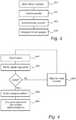
- Fig. 4is a flow chart schematically illustrating such a method.
- the methodmay be implemented in the authentication device 30 by storing computer program code portions in the device 30, a processor controlling the method described hereinafter
- step 401the reader 40 reads the label 16 provided on the cuvette 10.
- step 402the authentication device 30 verifies the digital signature comprised in the label 16.
- the verificationis performed by using the public key corresponding to the private key used when producing the digital signature. Only if this verification is valid, the next step 403 is performed, otherwise the program control proceeds to step 405, waiting for next cuvette to be verified.
- step 403after a valid verification of the digital signature and the cuvette has been inserted into the measuring device 20, the unique pattern is detected for example by means of taking an image of the pattern from a designated authentication portion 14 outside the sample holding portion of the cuvette 10. A representation of the detected unique pattern is transmitted to the authentication device.
- step 404the digital representation that was read from the label 16 in step 301 is compared to the detected unique pattern, by the authentication device 30. If the consistency between these two is not sufficient the cuvette 10 is considered to be fake, and is not compatible with the measuring device 20 in question.
- Step 401 and 403 of reading the label 16 and detecting the unique patternmay moreover be executed at the same time, by the measuring device 20, if the properties of the cuvette 10 allow that the same technique is used for both reading the label and detecting the unique pattern, for example by taking an image using a microscope. This may be achieved by using a photoactive dye inside the cuvette 10 which can be modified with a laser. Moreover, it requires that the label 16 and the unique pattern 14 be arranged adjacent to each other.
- the particle propertiesmay be of any measurable kind, such as intensity, or color
- the unique patternmay be measured by various detection techniques and combinations of these, such as only reflective measurements, or both reflective and transmission measurements, etc.
Landscapes
- Chemical & Material Sciences (AREA)
- Health & Medical Sciences (AREA)
- Analytical Chemistry (AREA)
- Engineering & Computer Science (AREA)
- General Physics & Mathematics (AREA)
- Physics & Mathematics (AREA)
- General Health & Medical Sciences (AREA)
- Chemical Kinetics & Catalysis (AREA)
- Clinical Laboratory Science (AREA)
- Theoretical Computer Science (AREA)
- Biochemistry (AREA)
- Multimedia (AREA)
- Immunology (AREA)
- Pathology (AREA)
- Life Sciences & Earth Sciences (AREA)
- Hematology (AREA)
- Automatic Analysis And Handling Materials Therefor (AREA)
- Investigating Or Analysing Biological Materials (AREA)
- Optical Measuring Cells (AREA)
- Immobilizing And Processing Of Enzymes And Microorganisms (AREA)
Description
- The present invention relates to a cuvette for storing a biological sample to be analyzed by a measuring device. The invention also relates to a method for authentication of a cuvette.
- In health care today an increasing amount of analysis of biological samples are performed instantly at the point of care due to for example developed techniques in this area. The increasing use of biological analysis causes usage of an increased amount of disposable cuvettes on which a biological sample, such as a blood sample, is stored. When performing the analysis the cuvette is introduced to a measuring device that generates an analysis result.
- Low cost producers have noticed that the profit is made through selling such disposable cuvettes, rather than selling the actual measuring device to which a cuvette is introduced, whereby copying of cuvettes by low cost producers has become a problem. Cuvettes being produced by low cost producers impacts on the quality of cuvettes that leads to decreased reliability of analysis results when the copied cuvettes are used in measuring devices intended for the original cuvettes.
- In an attempt to give a unique identity to a known cuvette it could be labeled with an identifier, such as a bar code. However, labeling requires additional steps in the manufacturing process and such a label is moreover relatively easy to reproduce. Therefore, there is a need for a cuvette that cannot be easily reproduced to thereby obtain reliable test results and that can be easily authenticated to its corresponding measuring device.
WO 90/05903 WO 2006/020363 discloses a test tube containing particles embedded within the tube for authentication purposes. - In view of the above mentioned need, a general object of the present invention is to provide a cuvette that cannot be easily reproduced, and which is adapted to be authenticated. This and other objects are achieved through a cuvette for storing a biological sample to be analyzed by means of a predefined detection technique, the cuvette being formed from a moldable material, such as a plastic material, containing particles at a concentration within a predefined range. The particles are randomly distributed, in order to form a unique pattern, and the particles have measurable physical properties, so that the unique pattern is detectable using the predefined detection technique.
- The unique pattern of the present invention is used as an identifier of the cuvette, and is integrated in the material from which the cuvette is formed, by means of randomly distributed particles. The unique properties obtained by the randomly distributed particles render copying nearly impossible, since it is more complicated to distribute the particles in a predetermined pattern than to let them distribute randomly.
- Furthermore, the physical properties of the particles being measurable renders the unique pattern detectable, and by that means each cuvette holds a unique detectable identity. In addition, the pattern being detectable using the same detection technique as for detecting the biological sample forms a basis for a simple authentication of the cuvette using the same technique as when analyzing the biological sample. In other words, the cuvette of the present invention is less laborious to give the unique properties to, more complicated to copy than cuvettes of prior art, and adapted to easily be authenticated without requiring additional equipment.
- The cuvette may moreover have a handle portion and an introducible portion adapted to be introduced into a measuring device, at least a portion of the introducible portion being a sample holding portion for storing of a biological sample, wherein the unique pattern is comprised in the introducible portion outside the sample holding portion with the result that the unique pattern may be introduced to a measuring device together with the biological sample. The unique pattern being separated from the sample holding portion forms a basis for a correct analysis result as well as a correctly executed authentication of the cuvette.
- Further, the size of the particles may be in the order of micrometers, preferably ranging from 1 to 10 micrometers, such as micro beads, having the properties to be easily detected by detection techniques used for sample analysis. Furthermore, the particles may have such properties so that they easily distribute in the moldable material, which hence simplifies the manufacturing process, and the achievement of the unique pattern. An example of particle material is glass.
- The cuvette may be provided with a readable label, wherein the label contains a stored digital representation of the unique pattern, which forms a basis for a reliable authentication of the cuvette, where the stored digital representation may be compared to the unique pattern of the cuvette.
- The label may be readable using the same detection technique. In this case, the label is preferably arranged adjacent to the unique pattern, so that only one image is enough to both read the label and detect the unique pattern.
- Further, the physical properties may be at least one of reflectivity and transmittivity, in which case the detection technique may be optical detection of an image. This is a suitable technique for obtaining a representation of the unique pattern and to read the stored representation of the label, which technique is also a common technique for analyzing a biological sample. Other detection techniques include for example chemical analysis.
- According to a second aspect of the present invention there is provided a method for manufacturing a cuvette for storing a biological sample to be analyzed by means of a predefined detection technique. The method comprises the steps of providing a moldable material containing particles at a concentration within a predefined range, which particles have measurable physical properties; and forming a cuvette from the material, so that the particles are randomly distributed, in order to form a unique pattern, which is detectable using the detection technique.
- Providing the particles constituting the unique properties already in the manufacturing process is a relatively simple way to achieve unique properties, since it belongs to the nature of such particles, such as micro beams, to distribute randomly in the moldable material. Moreover, as described in relation to the cuvette according to the present invention copying such a cuvette is nearly impossible, since it is much more complicated to manufacture a cuvette by inserting particles in a predetermined pattern, than to let them distribute randomly.
- According to a third aspect of the present invention, there is provided a method for authenticating a cuvette formed from a moldable material comprising particles having measurable physical properties, the particles being randomly distributed, in order to form a unique, detectable pattern. The method comprises the steps of introducing the cuvette into a measuring device that is intended to analyze a biological sample, such as a blood sample; and detecting the unique pattern of the cuvette using the measuring device.
- Re-using a measuring device that is intended for performing an analysis of a biological sample for also detecting the unique pattern of the cuvette is efficient and practical. No additional detection device is hence required for this purpose, and the effect of with certainty preventing usage of copied products in a measuring device is obtained.
- When the cuvette is provided with a label comprising a stored digital representation of the unique pattern the method may further comprise the steps of reading the stored digital representation from the label to be verified; and comparing the stored digital representation with the detected unique pattern to thereby achieve a reliable result of authentication.
- Moreover, the label may be readable using equipment used to detect the unique pattern, so as to be readable by the measuring device. In this case, the label is preferably provided adjacent to the unique pattern, so that only one image is enough to both read the label and detect the unique pattern.
- In the following, embodiments of the present invention will be described in detail, with reference to the accompanying, exemplifying drawings on which:
Fig. 1 is a perspective view of a cuvette and a measuring device according to the present invention.Fig. 2 is a perspective view of a system for analyzing a biological sample and for authenticating a cuvette.Fig. 3 is a flow chart schematically illustrating an exemplary method for analyzing a biological sample of the present invention.Fig. 4 is a flow chart schematically illustrating an exemplary method for authenticating a cuvette performed by the measuring device.- The present invention will be mainly described hereinafter with reference to a
cuvette 10 illustrated inFig. 1 . - The
cuvette 10 is formed from a moldable material, e.g. a plastic material, that comprisesparticles 15a-b, such as glass micro beads, that are randomly distributed in the moldable material before thecuvette 10 is molded. The properties of theparticles 15a-b are moreover measurable. - The
cuvette 10 comprises ahandle portion 11 and anintroducible portion 12. Thehandle portion 11 of thecuvette 10 is adapted to be held by a user when storing a blood sample from a patient, and for simplifying insertion of theintroducible portion 12 of thecuvette 10 into a measuring device. Theintroducible portion 12 of thecuvette 10 is further divided into asample holding portion 13, where the blood sample is stored, and anauthentication portion 14, adapted to uniquely identify thecuvette 10, by the properties achieved byparticles 15a-b. Theparticles 15a-b form a unique pattern due to the unique location and orientation in relation to each other of theseparticles 15a-b for eachcuvette 10. Since the properties of theparticles 15a-b are measurable the unique pattern may be both detected and stored, for example by means of taking an image of the pattern. The unique pattern of theauthentication portion 14 of thecuvette 10 is as mentioned dedicated for the purpose of identifying the cuvette. - There is a
label 16 provided on the cuvette, that contains a stored digital representation of the unique pattern of the cuvette, and alternatively also a digital signature. In more detail the label may for example have been produced by first taking an image of theauthentication portion 14 of the unique pattern, which image has been transformed into a compact digital representation. The signature has then been generated from the digital representation for example by means of using a signing algorithm. Signing may be performed by using for example a private key of a certification authority. The digital representation and the digital signature has thereafter been combined into so called enrolment data, which is printed or otherwise provided as alabel 16 on thecuvette 10, in the form of for example a bar code, a block code, or an electronic identifier, such as an RFID. Alternatively, the digital representation is stored e.g. in a database in the device that performs the authentication method. - By digitally signing the digital representation it is more difficult for a malicious party to generate valid data, since it also requires a valid signature.
- In
Fig. 2 a system for analyzing a blood sample that is stored on the cuvette and for authenticating the cuvette is illustrated. The system comprises a measuringdevice 20 intended to perform blood sample analysis, anauthentication device 30 connected to the measuringdevice 20, and areader 40 connected to theauthentication device 30. - The measuring
device 20 has adisplay 21 for displaying analysis data etc, and anopening 22 in which thecuvette 10 may be inserted. The measuringdevice 20 is intended for analyzing a blood sample, which is achieved through image detection techniques. As an alternative to optical detection of an image, the detection may be based on for example electrical or chemical techniques. In operation thecuvette 10 is inserted to the measuringdevice 20, whereby the unique pattern of theauthentication portion 14 may be detected and the blood sample which is stored on thesample holding portion 13 of thecuvette 10 may be analyzed using the same detection technique, performed by the measuringdevice 20. - The
reader 40 is adapted to read the label of thecuvette 10, and depending on the type oflabel 16, thereader 40 may be for example a bar code reader or a block code reader. - The
authentication device 30 is arranged to receive data which is read by thereader 40 and to authenticate thecuvette 10 using this information, which is further described in relation toFigs. 3 and 4 . Theauthentication device 30 may be a micro processor. - Alternatively the
reader 40 and theauthentication device 30 are part of the measuring device. - An example of a method for analyzing a biological sample, here a blood sample, will now be described with reference to
Fig. 3 which is a flow chart schematically illustrating such a method. - First, in
step 301, a blood sample is taken from a patient at a point of care, and is stored at the sample holding portion of thecuvette 10. Thereafter, instep 302, thecuvette 10 is inserted to theopening 22 of the measuringdevice 20. - In
step 303 the cuvette is authenticated by means of an authentication method that will be further described with reference toFig. 4 . If the authentication is successful, meaning that thecuvette 10 is an original cuvette that is to be used in the measuringdevice 20 in question, step 204 is performed. - In
step 304 the blood sample is analyzed according to conventional methods performed by the measuringdevice 20. - An example of a method for authenticating a cuvette will now be described with reference to
Fig. 4 which is a flow chart schematically illustrating such a method. The method may be implemented in theauthentication device 30 by storing computer program code portions in thedevice 30, a processor controlling the method described hereinafter - First, in
step 401, thereader 40 reads thelabel 16 provided on thecuvette 10. - The digital signature and the digital representation are transmitted to the
authentication device 30. Thereafter, instep 402, theauthentication device 30 verifies the digital signature comprised in thelabel 16. The verification is performed by using the public key corresponding to the private key used when producing the digital signature. Only if this verification is valid, thenext step 403 is performed, otherwise the program control proceeds to step 405, waiting for next cuvette to be verified. - In
step 403, after a valid verification of the digital signature and the cuvette has been inserted into the measuringdevice 20, the unique pattern is detected for example by means of taking an image of the pattern from a designatedauthentication portion 14 outside the sample holding portion of thecuvette 10. A representation of the detected unique pattern is transmitted to the authentication device. - Next, in
step 404, the digital representation that was read from thelabel 16 instep 301 is compared to the detected unique pattern, by theauthentication device 30. If the consistency between these two is not sufficient thecuvette 10 is considered to be fake, and is not compatible with the measuringdevice 20 in question. - In case there is no digital signature the steps concerning the digital signature may accordingly be left out of the method.
- Step 401 and 403 of reading the
label 16 and detecting the unique pattern may moreover be executed at the same time, by the measuringdevice 20, if the properties of thecuvette 10 allow that the same technique is used for both reading the label and detecting the unique pattern, for example by taking an image using a microscope. This may be achieved by using a photoactive dye inside thecuvette 10 which can be modified with a laser. Moreover, it requires that thelabel 16 and theunique pattern 14 be arranged adjacent to each other. - The person skilled in the art realizes that the present invention is not limited to the preferred embodiments. For example the particle properties may be of any measurable kind, such as intensity, or color, the unique pattern may be measured by various detection techniques and combinations of these, such as only reflective measurements, or both reflective and transmission measurements, etc.
- Such and other obvious modifications must be considered to be within the scope of the present invention, as it is defined by the appended claims. It should be noted that the above-mentioned embodiments illustrate rather than limit the invention, and that those skilled in the art will be able to design many alternative embodiments without departing from the scope of the appended claims. In the claims, any reference signs placed between parentheses shall not be construed as limiting to the claim. The word "comprising" does not exclude the presence of other elements or steps than those listed in the claim. The word "a" or "an" preceding an element does not exclude the presence of a plurality of such elements. Further, a single unit may perform the functions of several means recited in the claims.
Claims (15)
- A cuvette (10) for storing a biological sample, arranged such that this biological sample can be analyzed by means of a predefined detection technique, said cuvette (10) being formed from a moldable material containing particles (15a-b) at a concentration within a predefined range, said particles (15a-b) being randomly distributed in order to form a unique pattern (14),
said particles (15a-b) having measurable physical properties so that said unique pattern (14) is detectable using said predefined detection technique. - The cuvette (10) according to claim 1, having a handle portion (11) and an introducible portion (12) adapted to be introduced into a measuring device (12), at least a portion of said introducible portion (12) being a sample holding portion (13) for storing of a biological sample, wherein said unique pattern (14) is comprised in said introducible portion (12) outside said sample holding portion (13).
- The cuvette (10) according to claim 1, wherein the size of said particles (15a-b) are in the order of micrometers, preferably ranging from 1 to 10 micrometers.
- The cuvette (10) according to claim 1, further provided with a readable label (16), wherein said label (16) contains a stored digital representation of said unique pattern (14).
- The cuvette (10) according to claim 4, wherein said label (16) is readable using said detection technique, and arranged adjacent to said unique pattern (14).
- The cuvette (10) according to claim 1, wherein the physical properties are at least one of reflectivity and transmittivity.
- The cuvette (10) according to claim 6, wherein said detection technique is optical detection of an image.
- A method for manufacturing a cuvette (10) for storing a biological sample to be analyzed by means of a predefined detection technique, comprising the steps of:providing a moldable material containing particles (15a-b) at a concentration within a predefined range, which particles (15a-b) have measurable physical properties; andforming a cuvette (10) from said material, so that said particles (15a-b) are randomly distributed, in order to form a unique pattern (14), which is detectable using said detection technique.
- The method for manufacturing a cuvette (10) further comprising the step of providing said cuvette (10) with a readable label (16) containing a stored digital representation of said unique pattern (14).
- The method of claim 9, wherein said label (16) is provided adjacent to said unique pattern (14), and is readable using said detection technique.
- A method for authenticating a cuvette (10) according to claim 1, which method comprises the steps of:introducing (302) the cuvette (10) into a measuring device (20) that is intended to analyze the biological sample, such as a blood sample;detecting (403) the unique pattern (14) using said measuring device (20).
- The method according to claim 11, wherein the cuvette (10) is provided with a label (16), said label (16) comprising a stored digital representation of the unique pattern (14) the method further comprising the steps of
reading (401) said stored digital representation from the label (16); and
comparing (404) the stored digital representation with the detected unique pattern (14). - A method for analyzing a biological sample, such as a blood sample, comprising the steps of:storing (301) the biological sample in a cuvette as claimed in claim 1;authenticating (303) the cuvette (10) by means of the method of claim 11; andanalyzing (304) said biological sample with said measuring device.
- A system for analyzing a biological sample comprising:a measuring device (20) adapted to analyze (304) a biological sample stored in the cuvette (10) of claim 1, and to detect (403) the unique pattern (14) of randomly-distributed particles in the moldable material of the cuvette; andan authentication device (30) adapted to receive information from the measuring device (20); and to authenticate (303) said cuvette (10) based on said information.
- The system in claim 14, further comprising:a reader (40) adapted to read a label (16) provided on said cuvette (10) and storing a digital representation of the unique pattern (14);said authentication device (30) further being adapted to receive information from the reader (40).
Priority Applications (1)
| Application Number | Priority Date | Filing Date | Title |
|---|---|---|---|
| EP09756181.5AEP2355930B1 (en) | 2008-11-06 | 2009-11-02 | Cuvette and method for authenticating a cuvette |
Applications Claiming Priority (3)
| Application Number | Priority Date | Filing Date | Title |
|---|---|---|---|
| EP08168446 | 2008-11-06 | ||
| EP09756181.5AEP2355930B1 (en) | 2008-11-06 | 2009-11-02 | Cuvette and method for authenticating a cuvette |
| PCT/IB2009/054859WO2010052634A2 (en) | 2008-11-06 | 2009-11-02 | Cuvette and method for authenticating a cuvette |
Publications (2)
| Publication Number | Publication Date |
|---|---|
| EP2355930A2 EP2355930A2 (en) | 2011-08-17 |
| EP2355930B1true EP2355930B1 (en) | 2018-01-10 |
Family
ID=41531537
Family Applications (1)
| Application Number | Title | Priority Date | Filing Date |
|---|---|---|---|
| EP09756181.5AActiveEP2355930B1 (en) | 2008-11-06 | 2009-11-02 | Cuvette and method for authenticating a cuvette |
Country Status (9)
| Country | Link |
|---|---|
| US (1) | US8665431B2 (en) |
| EP (1) | EP2355930B1 (en) |
| JP (1) | JP2012507705A (en) |
| CN (2) | CN106040330B (en) |
| AP (1) | AP2011005741A0 (en) |
| BR (1) | BRPI0916111A2 (en) |
| RU (1) | RU2509296C2 (en) |
| WO (1) | WO2010052634A2 (en) |
| ZA (1) | ZA201104159B (en) |
Families Citing this family (10)
| Publication number | Priority date | Publication date | Assignee | Title |
|---|---|---|---|---|
| DE102010033181A1 (en)* | 2010-08-03 | 2012-02-09 | Eppendorf Ag | A method of recognizing a confusable item |
| EP2511691A1 (en)* | 2011-04-14 | 2012-10-17 | Qiagen GmbH | System and method for calibration of an optical measuring apparatus |
| US9213043B2 (en) | 2012-05-15 | 2015-12-15 | Wellstat Diagnostics, Llc | Clinical diagnostic system including instrument and cartridge |
| US9075042B2 (en) | 2012-05-15 | 2015-07-07 | Wellstat Diagnostics, Llc | Diagnostic systems and cartridges |
| US9625465B2 (en) | 2012-05-15 | 2017-04-18 | Defined Diagnostics, Llc | Clinical diagnostic systems |
| US10421956B2 (en) | 2014-01-17 | 2019-09-24 | General Electric Company | Electric pulse generation systems using capacitive coupling |
| US9708597B2 (en)* | 2014-01-17 | 2017-07-18 | General Electric Company | Electric pulse generation systems using capacitive coupling |
| WO2016188738A1 (en)* | 2015-05-26 | 2016-12-01 | F. Hoffmann-La Roche Ag | Point of care testing poct system |
| EP3347694B8 (en)* | 2015-07-01 | 2021-04-21 | Horiba Instruments Incorporated | Cuvette assembly for optical microscopy of nanoparticles in liquids |
| US10088468B2 (en)* | 2016-02-04 | 2018-10-02 | Nova Biomedical Corporation | Analyte system and method for determining hemoglobin parameters in whole blood |
Family Cites Families (13)
| Publication number | Priority date | Publication date | Assignee | Title |
|---|---|---|---|---|
| GB8713649D0 (en)* | 1987-06-11 | 1987-07-15 | Pa Consulting Services | Biological assay |
| US5098661A (en)* | 1988-11-16 | 1992-03-24 | Medical Laboratory Automation, Inc. | Coded cuvette for use in testing apparatus |
| EP1586379B1 (en)* | 2000-04-19 | 2007-06-13 | Corning Incorporated | Method of manufacture of a multi-well plate |
| WO2003026558A2 (en) | 2001-09-24 | 2003-04-03 | Scott Laboratories, Inc. | Methods and apparatuses for assuring quality and safety of drug administration and medical products and kits |
| US7619819B2 (en)* | 2002-08-20 | 2009-11-17 | Illumina, Inc. | Method and apparatus for drug product tracking using encoded optical identification elements |
| DE60323941D1 (en)* | 2003-04-30 | 2008-11-20 | Hewlett Packard Development Co | Authentication method and system |
| EP1882239A1 (en) | 2005-05-11 | 2008-01-30 | Koninklijke Philips Electronics N.V. | Authenticating banknotes or other physical objects |
| US7677438B2 (en) | 2005-06-29 | 2010-03-16 | Microsoft Corporation | Radio frequency certificates of authenticity |
| WO2007023420A1 (en) | 2005-08-23 | 2007-03-01 | Koninklijke Philips Electronics N.V. | Information carrier authentication with a physical one-way function |
| US20080200838A1 (en) | 2005-11-28 | 2008-08-21 | Daniel Goldberger | Wearable, programmable automated blood testing system |
| GB0609411D0 (en)* | 2006-05-12 | 2006-06-21 | Diasys Europ Ltd | Combination of automated apparatus and container for use therewith |
| RU2321638C2 (en)* | 2006-05-23 | 2008-04-10 | Закрытое акционерное общество "Молекулярно-медицинские технологии" | Method for preparing multifunctional multichip, multichip for successive or parallel screening biopolymers, method for analysis of biopolymers and set for realization of method |
| EP2150345A1 (en)* | 2007-04-20 | 2010-02-10 | Bioinnovatons Oy | Vessel for accurate analysis |
- 2009
- 2009-11-02EPEP09756181.5Apatent/EP2355930B1/enactiveActive
- 2009-11-02RURU2011122674/05Apatent/RU2509296C2/ennot_activeIP Right Cessation
- 2009-11-02BRBRPI0916111Apatent/BRPI0916111A2/ennot_activeApplication Discontinuation
- 2009-11-02CNCN201610520983.0Apatent/CN106040330B/enactiveActive
- 2009-11-02APAP2011005741Apatent/AP2011005741A0/enunknown
- 2009-11-02CNCN2009801443748Apatent/CN102209589A/enactivePending
- 2009-11-02USUS13/126,329patent/US8665431B2/enactiveActive
- 2009-11-02WOPCT/IB2009/054859patent/WO2010052634A2/enactiveApplication Filing
- 2009-11-02JPJP2011533917Apatent/JP2012507705A/enactivePending
- 2011
- 2011-06-03ZAZA2011/04159Apatent/ZA201104159B/enunknown
Also Published As
| Publication number | Publication date |
|---|---|
| RU2011122674A (en) | 2012-12-20 |
| WO2010052634A2 (en) | 2010-05-14 |
| CN102209589A (en) | 2011-10-05 |
| WO2010052634A3 (en) | 2010-09-30 |
| ZA201104159B (en) | 2012-11-28 |
| AP2011005741A0 (en) | 2011-06-30 |
| CN106040330B (en) | 2018-09-18 |
| US8665431B2 (en) | 2014-03-04 |
| US20110259091A1 (en) | 2011-10-27 |
| RU2509296C2 (en) | 2014-03-10 |
| JP2012507705A (en) | 2012-03-29 |
| BRPI0916111A2 (en) | 2015-11-03 |
| CN106040330A (en) | 2016-10-26 |
| EP2355930A2 (en) | 2011-08-17 |
Similar Documents
| Publication | Publication Date | Title |
|---|---|---|
| EP2355930B1 (en) | Cuvette and method for authenticating a cuvette | |
| CN111919215B (en) | Authentication of packaged products | |
| US8996878B2 (en) | Controlling an analysis system of biological samples | |
| EP2313787B1 (en) | Apparatus, method and article to perform assays using assay strips | |
| JP5130103B2 (en) | System setting method for color test chip analyzer | |
| JP6081917B2 (en) | Guided systematic inspection kit | |
| EP1669910A2 (en) | Biometric system | |
| BRPI0818877B1 (en) | METHOD AND SYSTEM FOR SEMI-QUANTITATIVE OR QUANTITATIVE TEST ANALYSIS | |
| CA3091428A1 (en) | Secure machine readable code-embedded diagnostic test | |
| US11955239B2 (en) | Systems, methods, and devices for non-human readable diagnostic tests | |
| USRE39226E1 (en) | Changeable machine readable assaying indicia | |
| CN101776583B (en) | Method and system for preventing copy of platform | |
| US10340032B2 (en) | Rapidly configurable drug detection system with enhanced confidentiality | |
| EP3680804B1 (en) | System and method for reading information code | |
| AU5782001A (en) | Quality control method and apparatus for automated analyses of biologic matter | |
| JP7153807B2 (en) | Genuine product automatic authentication method | |
| CN112597810A (en) | Identity document authentication method and system | |
| US20240410910A1 (en) | Machine testing quality verification | |
| US20220157415A1 (en) | System and method for examining test samples on a virtual platform | |
| JP2007207150A (en) | Biological information processing apparatus, abnormality determination program for biological information processing apparatus, and abnormality determination method thereof | |
| KR20100127705A (en) | Identification device | |
| CN117934801A (en) | Anti-counterfeiting method and device for concrete test piece, computer equipment and storage medium | |
| CA3146421A1 (en) | Virtual authentication detection | |
| Interoperable | Federal Identity, Credentialing, and Access Management | |
| CN101413879A (en) | System setting method of color generation chip analyzer |
Legal Events
| Date | Code | Title | Description |
|---|---|---|---|
| PUAI | Public reference made under article 153(3) epc to a published international application that has entered the european phase | Free format text:ORIGINAL CODE: 0009012 | |
| 17P | Request for examination filed | Effective date:20110606 | |
| AK | Designated contracting states | Kind code of ref document:A2 Designated state(s):AT BE BG CH CY CZ DE DK EE ES FI FR GB GR HR HU IE IS IT LI LT LU LV MC MK MT NL NO PL PT RO SE SI SK SM TR | |
| DAX | Request for extension of the european patent (deleted) | ||
| RAP1 | Party data changed (applicant data changed or rights of an application transferred) | Owner name:KONINKLIJKE PHILIPS N.V. | |
| 17Q | First examination report despatched | Effective date:20141008 | |
| GRAP | Despatch of communication of intention to grant a patent | Free format text:ORIGINAL CODE: EPIDOSNIGR1 | |
| INTG | Intention to grant announced | Effective date:20170719 | |
| GRAS | Grant fee paid | Free format text:ORIGINAL CODE: EPIDOSNIGR3 | |
| GRAA | (expected) grant | Free format text:ORIGINAL CODE: 0009210 | |
| AK | Designated contracting states | Kind code of ref document:B1 Designated state(s):AT BE BG CH CY CZ DE DK EE ES FI FR GB GR HR HU IE IS IT LI LT LU LV MC MK MT NL NO PL PT RO SE SI SK SM TR | |
| REG | Reference to a national code | Ref country code:GB Ref legal event code:FG4D | |
| REG | Reference to a national code | Ref country code:CH Ref legal event code:EP Ref country code:AT Ref legal event code:REF Ref document number:961805 Country of ref document:AT Kind code of ref document:T Effective date:20180115 | |
| REG | Reference to a national code | Ref country code:IE Ref legal event code:FG4D | |
| REG | Reference to a national code | Ref country code:DE Ref legal event code:R096 Ref document number:602009050335 Country of ref document:DE | |
| REG | Reference to a national code | Ref country code:NL Ref legal event code:MP Effective date:20180110 | |
| REG | Reference to a national code | Ref country code:AT Ref legal event code:MK05 Ref document number:961805 Country of ref document:AT Kind code of ref document:T Effective date:20180110 | |
| PG25 | Lapsed in a contracting state [announced via postgrant information from national office to epo] | Ref country code:NL Free format text:LAPSE BECAUSE OF FAILURE TO SUBMIT A TRANSLATION OF THE DESCRIPTION OR TO PAY THE FEE WITHIN THE PRESCRIBED TIME-LIMIT Effective date:20180110 | |
| PG25 | Lapsed in a contracting state [announced via postgrant information from national office to epo] | Ref country code:FI Free format text:LAPSE BECAUSE OF FAILURE TO SUBMIT A TRANSLATION OF THE DESCRIPTION OR TO PAY THE FEE WITHIN THE PRESCRIBED TIME-LIMIT Effective date:20180110 Ref country code:LT Free format text:LAPSE BECAUSE OF FAILURE TO SUBMIT A TRANSLATION OF THE DESCRIPTION OR TO PAY THE FEE WITHIN THE PRESCRIBED TIME-LIMIT Effective date:20180110 Ref country code:CY Free format text:LAPSE BECAUSE OF FAILURE TO SUBMIT A TRANSLATION OF THE DESCRIPTION OR TO PAY THE FEE WITHIN THE PRESCRIBED TIME-LIMIT Effective date:20180110 Ref country code:NO Free format text:LAPSE BECAUSE OF FAILURE TO SUBMIT A TRANSLATION OF THE DESCRIPTION OR TO PAY THE FEE WITHIN THE PRESCRIBED TIME-LIMIT Effective date:20180410 Ref country code:ES Free format text:LAPSE BECAUSE OF FAILURE TO SUBMIT A TRANSLATION OF THE DESCRIPTION OR TO PAY THE FEE WITHIN THE PRESCRIBED TIME-LIMIT Effective date:20180110 Ref country code:HR Free format text:LAPSE BECAUSE OF FAILURE TO SUBMIT A TRANSLATION OF THE DESCRIPTION OR TO PAY THE FEE WITHIN THE PRESCRIBED TIME-LIMIT Effective date:20180110 | |
| PG25 | Lapsed in a contracting state [announced via postgrant information from national office to epo] | Ref country code:IS Free format text:LAPSE BECAUSE OF FAILURE TO SUBMIT A TRANSLATION OF THE DESCRIPTION OR TO PAY THE FEE WITHIN THE PRESCRIBED TIME-LIMIT Effective date:20180510 Ref country code:BG Free format text:LAPSE BECAUSE OF FAILURE TO SUBMIT A TRANSLATION OF THE DESCRIPTION OR TO PAY THE FEE WITHIN THE PRESCRIBED TIME-LIMIT Effective date:20180410 Ref country code:AT Free format text:LAPSE BECAUSE OF FAILURE TO SUBMIT A TRANSLATION OF THE DESCRIPTION OR TO PAY THE FEE WITHIN THE PRESCRIBED TIME-LIMIT Effective date:20180110 Ref country code:PL Free format text:LAPSE BECAUSE OF FAILURE TO SUBMIT A TRANSLATION OF THE DESCRIPTION OR TO PAY THE FEE WITHIN THE PRESCRIBED TIME-LIMIT Effective date:20180110 Ref country code:SE Free format text:LAPSE BECAUSE OF FAILURE TO SUBMIT A TRANSLATION OF THE DESCRIPTION OR TO PAY THE FEE WITHIN THE PRESCRIBED TIME-LIMIT Effective date:20180110 Ref country code:LV Free format text:LAPSE BECAUSE OF FAILURE TO SUBMIT A TRANSLATION OF THE DESCRIPTION OR TO PAY THE FEE WITHIN THE PRESCRIBED TIME-LIMIT Effective date:20180110 Ref country code:GR Free format text:LAPSE BECAUSE OF FAILURE TO SUBMIT A TRANSLATION OF THE DESCRIPTION OR TO PAY THE FEE WITHIN THE PRESCRIBED TIME-LIMIT Effective date:20180411 | |
| REG | Reference to a national code | Ref country code:DE Ref legal event code:R097 Ref document number:602009050335 Country of ref document:DE | |
| PG25 | Lapsed in a contracting state [announced via postgrant information from national office to epo] | Ref country code:IT Free format text:LAPSE BECAUSE OF FAILURE TO SUBMIT A TRANSLATION OF THE DESCRIPTION OR TO PAY THE FEE WITHIN THE PRESCRIBED TIME-LIMIT Effective date:20180110 Ref country code:EE Free format text:LAPSE BECAUSE OF FAILURE TO SUBMIT A TRANSLATION OF THE DESCRIPTION OR TO PAY THE FEE WITHIN THE PRESCRIBED TIME-LIMIT Effective date:20180110 Ref country code:RO Free format text:LAPSE BECAUSE OF FAILURE TO SUBMIT A TRANSLATION OF THE DESCRIPTION OR TO PAY THE FEE WITHIN THE PRESCRIBED TIME-LIMIT Effective date:20180110 | |
| PLBE | No opposition filed within time limit | Free format text:ORIGINAL CODE: 0009261 | |
| STAA | Information on the status of an ep patent application or granted ep patent | Free format text:STATUS: NO OPPOSITION FILED WITHIN TIME LIMIT | |
| PG25 | Lapsed in a contracting state [announced via postgrant information from national office to epo] | Ref country code:DK Free format text:LAPSE BECAUSE OF FAILURE TO SUBMIT A TRANSLATION OF THE DESCRIPTION OR TO PAY THE FEE WITHIN THE PRESCRIBED TIME-LIMIT Effective date:20180110 Ref country code:SK Free format text:LAPSE BECAUSE OF FAILURE TO SUBMIT A TRANSLATION OF THE DESCRIPTION OR TO PAY THE FEE WITHIN THE PRESCRIBED TIME-LIMIT Effective date:20180110 Ref country code:SM Free format text:LAPSE BECAUSE OF FAILURE TO SUBMIT A TRANSLATION OF THE DESCRIPTION OR TO PAY THE FEE WITHIN THE PRESCRIBED TIME-LIMIT Effective date:20180110 Ref country code:CZ Free format text:LAPSE BECAUSE OF FAILURE TO SUBMIT A TRANSLATION OF THE DESCRIPTION OR TO PAY THE FEE WITHIN THE PRESCRIBED TIME-LIMIT Effective date:20180110 | |
| 26N | No opposition filed | Effective date:20181011 | |
| PG25 | Lapsed in a contracting state [announced via postgrant information from national office to epo] | Ref country code:SI Free format text:LAPSE BECAUSE OF FAILURE TO SUBMIT A TRANSLATION OF THE DESCRIPTION OR TO PAY THE FEE WITHIN THE PRESCRIBED TIME-LIMIT Effective date:20180110 | |
| REG | Reference to a national code | Ref country code:CH Ref legal event code:PL | |
| PG25 | Lapsed in a contracting state [announced via postgrant information from national office to epo] | Ref country code:LU Free format text:LAPSE BECAUSE OF NON-PAYMENT OF DUE FEES Effective date:20181102 Ref country code:MC Free format text:LAPSE BECAUSE OF FAILURE TO SUBMIT A TRANSLATION OF THE DESCRIPTION OR TO PAY THE FEE WITHIN THE PRESCRIBED TIME-LIMIT Effective date:20180110 | |
| REG | Reference to a national code | Ref country code:BE Ref legal event code:MM Effective date:20181130 | |
| REG | Reference to a national code | Ref country code:IE Ref legal event code:MM4A | |
| PG25 | Lapsed in a contracting state [announced via postgrant information from national office to epo] | Ref country code:LI Free format text:LAPSE BECAUSE OF NON-PAYMENT OF DUE FEES Effective date:20181130 Ref country code:CH Free format text:LAPSE BECAUSE OF NON-PAYMENT OF DUE FEES Effective date:20181130 | |
| PG25 | Lapsed in a contracting state [announced via postgrant information from national office to epo] | Ref country code:IE Free format text:LAPSE BECAUSE OF NON-PAYMENT OF DUE FEES Effective date:20181102 | |
| PG25 | Lapsed in a contracting state [announced via postgrant information from national office to epo] | Ref country code:BE Free format text:LAPSE BECAUSE OF NON-PAYMENT OF DUE FEES Effective date:20181130 | |
| PG25 | Lapsed in a contracting state [announced via postgrant information from national office to epo] | Ref country code:MT Free format text:LAPSE BECAUSE OF NON-PAYMENT OF DUE FEES Effective date:20181102 | |
| PG25 | Lapsed in a contracting state [announced via postgrant information from national office to epo] | Ref country code:TR Free format text:LAPSE BECAUSE OF FAILURE TO SUBMIT A TRANSLATION OF THE DESCRIPTION OR TO PAY THE FEE WITHIN THE PRESCRIBED TIME-LIMIT Effective date:20180110 | |
| PG25 | Lapsed in a contracting state [announced via postgrant information from national office to epo] | Ref country code:PT Free format text:LAPSE BECAUSE OF FAILURE TO SUBMIT A TRANSLATION OF THE DESCRIPTION OR TO PAY THE FEE WITHIN THE PRESCRIBED TIME-LIMIT Effective date:20180110 | |
| PG25 | Lapsed in a contracting state [announced via postgrant information from national office to epo] | Ref country code:HU Free format text:LAPSE BECAUSE OF FAILURE TO SUBMIT A TRANSLATION OF THE DESCRIPTION OR TO PAY THE FEE WITHIN THE PRESCRIBED TIME-LIMIT; INVALID AB INITIO Effective date:20091102 Ref country code:MK Free format text:LAPSE BECAUSE OF NON-PAYMENT OF DUE FEES Effective date:20180110 | |
| PGFP | Annual fee paid to national office [announced via postgrant information from national office to epo] | Ref country code:DE Payment date:20241128 Year of fee payment:16 | |
| PGFP | Annual fee paid to national office [announced via postgrant information from national office to epo] | Ref country code:GB Payment date:20241126 Year of fee payment:16 | |
| PGFP | Annual fee paid to national office [announced via postgrant information from national office to epo] | Ref country code:FR Payment date:20241126 Year of fee payment:16 |