EP2355732B1 - Reduction tool for spinal rod - Google Patents
Reduction tool for spinal rodDownload PDFInfo
- Publication number
- EP2355732B1 EP2355732B1EP09792475.7AEP09792475AEP2355732B1EP 2355732 B1EP2355732 B1EP 2355732B1EP 09792475 AEP09792475 AEP 09792475AEP 2355732 B1EP2355732 B1EP 2355732B1
- Authority
- EP
- European Patent Office
- Prior art keywords
- outer tube
- inner tube
- distal end
- tool
- bone fixation
- Prior art date
- Legal status (The legal status is an assumption and is not a legal conclusion. Google has not performed a legal analysis and makes no representation as to the accuracy of the status listed.)
- Active
Links
- 230000009467reductionEffects0.000titledescription30
- 210000000988bone and boneAnatomy0.000claimsdescription94
- 230000008878couplingEffects0.000claimsdescription5
- 238000010168coupling processMethods0.000claimsdescription5
- 238000005859coupling reactionMethods0.000claimsdescription5
- 238000000034methodMethods0.000description11
- 238000003780insertionMethods0.000description4
- 230000037431insertionEffects0.000description4
- 210000003205muscleAnatomy0.000description4
- 238000013459approachMethods0.000description3
- 239000007943implantSubstances0.000description2
- 208000014674injuryDiseases0.000description2
- 239000007787solidSubstances0.000description2
- 230000007480spreadingEffects0.000description2
- 210000001519tissueAnatomy0.000description2
- 230000008733traumaEffects0.000description2
- 208000004550Postoperative PainDiseases0.000description1
- 206010058907Spinal deformityDiseases0.000description1
- 230000007850degenerationEffects0.000description1
- 239000000835fiberSubstances0.000description1
- 238000002513implantationMethods0.000description1
- 230000008676importEffects0.000description1
- 230000013011matingEffects0.000description1
- 238000012986modificationMethods0.000description1
- 230000004048modificationEffects0.000description1
- 230000000399orthopedic effectEffects0.000description1
- 230000002980postoperative effectEffects0.000description1
- 230000008569processEffects0.000description1
- 230000002035prolonged effectEffects0.000description1
- 238000011084recoveryMethods0.000description1
- 238000002271resectionMethods0.000description1
- 238000000926separation methodMethods0.000description1
- 210000004872soft tissueAnatomy0.000description1
- 238000001356surgical procedureMethods0.000description1
- 210000000115thoracic cavityAnatomy0.000description1
- 238000012800visualizationMethods0.000description1
Images


Classifications
- A—HUMAN NECESSITIES
- A61—MEDICAL OR VETERINARY SCIENCE; HYGIENE
- A61B—DIAGNOSIS; SURGERY; IDENTIFICATION
- A61B17/00—Surgical instruments, devices or methods
- A61B17/56—Surgical instruments or methods for treatment of bones or joints; Devices specially adapted therefor
- A61B17/58—Surgical instruments or methods for treatment of bones or joints; Devices specially adapted therefor for osteosynthesis, e.g. bone plates, screws or setting implements
- A61B17/88—Osteosynthesis instruments; Methods or means for implanting or extracting internal or external fixation devices
- A—HUMAN NECESSITIES
- A61—MEDICAL OR VETERINARY SCIENCE; HYGIENE
- A61B—DIAGNOSIS; SURGERY; IDENTIFICATION
- A61B17/00—Surgical instruments, devices or methods
- A61B17/56—Surgical instruments or methods for treatment of bones or joints; Devices specially adapted therefor
- A61B17/58—Surgical instruments or methods for treatment of bones or joints; Devices specially adapted therefor for osteosynthesis, e.g. bone plates, screws or setting implements
- A61B17/68—Internal fixation devices, including fasteners and spinal fixators, even if a part thereof projects from the skin
- A61B17/70—Spinal positioners or stabilisers, e.g. stabilisers comprising fluid filler in an implant
- A61B17/7074—Tools specially adapted for spinal fixation operations other than for bone removal or filler handling
- A61B17/7083—Tools for guidance or insertion of tethers, rod-to-anchor connectors, rod-to-rod connectors, or longitudinal elements
- A61B17/7086—Rod reducers, i.e. devices providing a mechanical advantage to allow a user to force a rod into or onto an anchor head other than by means of a rod-to-bone anchor locking element; rod removers
- A—HUMAN NECESSITIES
- A61—MEDICAL OR VETERINARY SCIENCE; HYGIENE
- A61B—DIAGNOSIS; SURGERY; IDENTIFICATION
- A61B17/00—Surgical instruments, devices or methods
- A61B17/56—Surgical instruments or methods for treatment of bones or joints; Devices specially adapted therefor
- A61B17/58—Surgical instruments or methods for treatment of bones or joints; Devices specially adapted therefor for osteosynthesis, e.g. bone plates, screws or setting implements
- A61B17/68—Internal fixation devices, including fasteners and spinal fixators, even if a part thereof projects from the skin
- A61B17/70—Spinal positioners or stabilisers, e.g. stabilisers comprising fluid filler in an implant
- A61B17/7074—Tools specially adapted for spinal fixation operations other than for bone removal or filler handling
- A61B17/7091—Tools specially adapted for spinal fixation operations other than for bone removal or filler handling for applying, tightening or removing longitudinal element-to-bone anchor locking elements, e.g. caps, set screws, nuts or wedges
- A—HUMAN NECESSITIES
- A61—MEDICAL OR VETERINARY SCIENCE; HYGIENE
- A61B—DIAGNOSIS; SURGERY; IDENTIFICATION
- A61B17/00—Surgical instruments, devices or methods
- A61B17/56—Surgical instruments or methods for treatment of bones or joints; Devices specially adapted therefor
- A61B17/58—Surgical instruments or methods for treatment of bones or joints; Devices specially adapted therefor for osteosynthesis, e.g. bone plates, screws or setting implements
- A61B17/68—Internal fixation devices, including fasteners and spinal fixators, even if a part thereof projects from the skin
- A61B17/84—Fasteners therefor or fasteners being internal fixation devices
- A61B17/86—Pins or screws or threaded wires; nuts therefor
- A—HUMAN NECESSITIES
- A61—MEDICAL OR VETERINARY SCIENCE; HYGIENE
- A61F—FILTERS IMPLANTABLE INTO BLOOD VESSELS; PROSTHESES; DEVICES PROVIDING PATENCY TO, OR PREVENTING COLLAPSING OF, TUBULAR STRUCTURES OF THE BODY, e.g. STENTS; ORTHOPAEDIC, NURSING OR CONTRACEPTIVE DEVICES; FOMENTATION; TREATMENT OR PROTECTION OF EYES OR EARS; BANDAGES, DRESSINGS OR ABSORBENT PADS; FIRST-AID KITS
- A61F2/00—Filters implantable into blood vessels; Prostheses, i.e. artificial substitutes or replacements for parts of the body; Appliances for connecting them with the body; Devices providing patency to, or preventing collapsing of, tubular structures of the body, e.g. stents
- A61F2/02—Prostheses implantable into the body
- A61F2/30—Joints
- A61F2/44—Joints for the spine, e.g. vertebrae, spinal discs
- A—HUMAN NECESSITIES
- A61—MEDICAL OR VETERINARY SCIENCE; HYGIENE
- A61B—DIAGNOSIS; SURGERY; IDENTIFICATION
- A61B17/00—Surgical instruments, devices or methods
- A61B17/56—Surgical instruments or methods for treatment of bones or joints; Devices specially adapted therefor
- A61B17/58—Surgical instruments or methods for treatment of bones or joints; Devices specially adapted therefor for osteosynthesis, e.g. bone plates, screws or setting implements
- A61B17/68—Internal fixation devices, including fasteners and spinal fixators, even if a part thereof projects from the skin
- A61B17/70—Spinal positioners or stabilisers, e.g. stabilisers comprising fluid filler in an implant
- A61B17/7001—Screws or hooks combined with longitudinal elements which do not contact vertebrae
- A61B17/7032—Screws or hooks with U-shaped head or back through which longitudinal rods pass
- A—HUMAN NECESSITIES
- A61—MEDICAL OR VETERINARY SCIENCE; HYGIENE
- A61B—DIAGNOSIS; SURGERY; IDENTIFICATION
- A61B17/00—Surgical instruments, devices or methods
- A61B17/56—Surgical instruments or methods for treatment of bones or joints; Devices specially adapted therefor
- A61B17/58—Surgical instruments or methods for treatment of bones or joints; Devices specially adapted therefor for osteosynthesis, e.g. bone plates, screws or setting implements
- A61B17/68—Internal fixation devices, including fasteners and spinal fixators, even if a part thereof projects from the skin
- A61B17/70—Spinal positioners or stabilisers, e.g. stabilisers comprising fluid filler in an implant
- A61B17/7001—Screws or hooks combined with longitudinal elements which do not contact vertebrae
- A61B17/7035—Screws or hooks, wherein a rod-clamping part and a bone-anchoring part can pivot relative to each other
- A61B17/7037—Screws or hooks, wherein a rod-clamping part and a bone-anchoring part can pivot relative to each other wherein pivoting is blocked when the rod is clamped
Definitions
- the present inventionrelates generally to orthopedics. More specifically, the present invention relates to a reduction tool and associated method for facilitating insertion of a longitudinal spinal rod into a rod-receiving channel formed in a bone fixation element.
- Spinal fixation systemswhich are used to correct spinal deformities and treat spinal degenerations generally include a plurality of bone fixation elements anchored in, for example, the pedicle of adjacent vertebrae.
- the bone fixation elementsare interconnected to one another by, for example, one or more elongated spinal rods.
- open approach surgical techniqueshave traditionally been employed. These open procedures generally involve large skin incisions and extensive tissue retraction and resection, all which may result in considerable post-operative pain and prolonged recovery time.
- a paraspinal approachis one form of minimally invasive technique and involves muscle splitting or muscle sparing in order to gain access to the posterior elements of the spine. Such a technique minimizes trauma to tissues adjacent the spine. Unlike open procedures where muscles and other soft tissue are cut, split, stripped and dissected, the paraspinal approach involves separation or splitting of the muscles along their fibers.
- Implanting a spinal rod fixation systemgenerally involves at least two steps: (i) placing bone fixation elements into the spine and (ii) inserting a rod between the bone fixation elements.
- Bone fixation elementsgenerally include a screw portion and a body portion. The screw portion is inserted into the spine and the body portion generally includes a rod-receiving channel for receiving and securing the spinal rod.
- the rodmay be inserted through an incision in the skin, which may be separate and distinct from the incision through which the bone fixation element(s) is placed. Alternatively, the rod may be inserted through the same incision as the bone fixation element(s).
- US 2005/0149036 A1discloses an instrument for engaging a bone fixation element, comprising an outer tube having an engagement feature for engaging the body portion of a bone fixation element.
- the instrumentfurther comprises an inner tube having an engagement member for engaging a locking cap of the bone fixation element.
- a threaded outer surface of the inner tubeengages a threaded inner surface of the outer tube when the inner tube is slidably disposed within the outer tube.
- the present inventionis directed to a reduction tool according to claim 1. It can be used for posterior spinal fixation to facilitate insertion of a longitudinal spinal rod into a rod-receiving channel formed in a bone fixation element.
- the reduction toolincludes an outer tube, an inner tube and a rotatable sleeve.
- the outer tubeis preferably sized and configured to transversely receive the spinal rod therethrough and is operatively coupled to the bone fixation element.
- the inner tubeis operatively coupled to a locking cap and is slidably disposed within the outer tube.
- the rotatable sleeveis operatively associated with the inner tube and the outer tube such that rotation of the sleeve moves the inner tube with respect to the outer tube thereby advancing the spinal rod into the rod-receiving channel formed in the bone fixation element and thereby coupling the locking cap to the bone fixation element to secure the rod to the bone fixation element.
- the reduction toolincludes an outer tube, an inner tube and a rotatable sleeve.
- the outer tubeincludes a proximal end, a distal end and a lumen defining an inner surface, the lumen extending from the proximal end to the distal end.
- the distal endincluding an engagement feature for engaging a body portion of a bone fixation element.
- the inner surfaceincluding a plurality of threads.
- the inner tubeincludes a proximal end, a distal end and a lumen extending from the proximal end to the distal end, the inner tube being slidably disposed within the lumen formed in the outer tube.
- the distal end of the inner tubeincluding an engagement member for engaging a locking cap.
- the rotatable sleeveincluding a proximal end, a distal end and a lumen extending from the proximal end to the distal end, the rotatable sleeve being rotatably coupled to the proximal end of the inner tube.
- the rotatable sleevefurther including a plurality of external threads for threadably engaging the threads formed on the inner surface of the outer tube such that rotation of the sleeve advances the inner tube with respect to the outer tube and hence downwardly and non-rotationally forces the locking cap and the elongated spinal rod into engagement with the body portion of the bone fixation element to provisionally lock the locking cap to the body portion of the bone fixation element and thus secure the spinal rod within the rod-receiving channel formed in the body portion of the bone fixation element.
- the outer tubepreferably also includes a pair of diametrically opposed slots extending from the distal end of the outer tube such that when the outer tube is engaged to the body portion of the bone fixation element, the diametrically opposed slots align with the rod-receiving channel formed in the bone fixation element.
- the diametrically opposed slotsbeing sized and configured to enable the elongated spinal rod to transversely extend therethrough.
- the outer tubepreferably also includes a pair of diametrically opposed guide slots extending from the proximal end of the outer tube for receiving one or more pins protruding from an outer surface of the inner tube. The guide slots being substantially aligned with the diametrically opposed slots extending from the distal end of the outer tube.
- the outer tubepreferably also includes a pivot point located longitudinally between each of the diametrically opposed slots extending from the distal end of the outer tube and each of the diametrically opposed guide slots extending from the proximal end of the outer tube so that the distal end of the outer tube can be spread apart to facilitate engagement with the body portion of the bone fixation element.
- the outer tubemay also include one or more guide recesses formed in the inner surface of the outer tube, the guide recesses extending from the proximal end of the outer tube. The guide recesses slidably receiving the engagement feature formed on the inner tube.
- the surgeonpreferably forms an incision at a desired location in a patient to access the patient's bones, for example, to access adjacent vertebral bodies.
- the surgeonimplants two or more bone fixation elements into the patient's bones through the incision, for example, the surgeon may insert one bone fixation element into each of the adjacent vertebral bodies.
- the outer tube of one of the reduction toolsis then coupled to each of the pre-implanted bone fixation elements.
- the spinal rodis then transversely inserted through each of the outer tubes.
- the surgeonthen inserts one of the inner tubes with the locking cap coupled thereto into each of the lumens formed in the outer tubes until the threads formed on the rotatable sleeves engage the corresponding threads formed on the outer tubes.
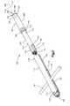
- a reduction tool 100for use in posterior spinal fixation to facilitate insertion of a longitudinal spinal rod 45 into a rod-receiving channel 26 formed in a bone fixation element 10.
- the inventionmay have other applications and uses and should not be limited to the structure or use described and illustrated.
- the reduction tool 100preferably includes an outer tube 110 sized and configured to transversely receive the spinal rod 45 therethrough, the outer tube 110 being operatively coupled to the bone fixation element 10, an inner tube 150 operatively coupled to a locking cap 40 and slidably disposed within the outer tube 110, and a rotatable sleeve 180 for rotatably advancing the inner tube 150 with respect to the outer tube 110 to advance the spinal rod 45 into the rod-receiving channel 26 formed in the bone fixation element 10 and to couple the locking cap 40 to the bone fixation element 10 to secure the rod 45 to the bone fixation element 10.
- the reduction tool 100will be described as and may generally be used in the spine (for example, in the lumbar, thoracic or cervical regions), those skilled in the art will appreciate that the reduction tool 100 may be used for fixation of other parts of the body such as, for example, joints, long bones or bones in the hand, face, feet, extremities, cranium, etc .
- the reduction tool 100may be used to facilitate insertion of the longitudinal spinal rod 45 into the rod-receiving channel 26 formed in the bone fixation element 10.
- the spinal rod 45may include, but not limited to, a solid rod, a non-solid rod, a flexible or dynamic rod, etc. It should be understood that the reduction tool 100 is not limited in use to any particular type of spinal rod 45.
- bone fixation element 10is used generally and may include, but are not limited to, poly-axial or mono-axial pedicle screws, hooks (both mono-axial and poly-axial) including pedicle hooks, transverse process hooks, sublaminar hook, or other fasteners, clamps or implants.
- the bone fixation element 10may include a bone anchor 12 (shown as a bone screw) having an enlarged, spherically-shaped head portion 14, a body portion 20 (shown as a top loading body portion) having an upper end 22, a lower end 24, a rod-receiving channel 26 (shown as a top loading U-shaped rod-receiving channel) defining a pair of spaced apart arms 28, 30, a sleeve 35 and a collet 36 slidably disposed within the body portion 20, at least a portion of the collet 36 being slidably disposed within the sleeve 35, and a locking cap 40 such as, for example, a set screw or a partial turn closure cap such as, for example, a quarter-turn closure cap or cam lock.
- a bone anchor 12shown as a bone screw
- body portion 20shown as a top loading body portion
- a rod-receiving channel 26shown as a top loading U-shaped rod-receiving channel
- the enlarged head portion 14 of the bone anchor 12may be separate from and be disposed within the lower end 24 of the body portion 20 so that the bone anchor 12 can poly-axial rotate with respect to the body portion 20.
- the bone anchor 12may be formed integral with the body portion 20 to form a monolithic structure which is sometimes referred to as a mono-axial pedicle screw or hook.
- the surgeoncan secure the position of the rod 45 with respect to the body portion 20 and the position of the bone anchor 12 with respect to the body portion 20 by, for example, rotating the locking cap 40.
- Rotation of the locking cap 40preferably causes the locking cap 40 to exert a downward force onto the spinal rod 45, which is received within the rod-receiving channel 26, which, in turn, causes the rod 45 to exert a downward force onto the sleeve 35 with causes the sleeve 35 to move with respect to the collet 36, which in turn causes the collet 36 to compress around the enlarged head portion 14 of the bone anchor 12 thereby securing the position of the bone anchor 12 with respect to the body portion 20.
- the reduction tool 100is not limited in use to any particular type of bone fixation element 10.
- Exemplary embodiments of bone fixation elements 10include those described in WO 2009/015100 A2 , WO 2006/116437 A2 WO 1998/052 482 A1 . It should be understood however that the present invention is not limited in use to any particular type of bone fixation element 10.
- the reduction tool 100includes an outer tube 110, an inner tube 150 and a rotatable sleeve 180.
- the outer tube 110is operably coupled to the inner tube 150, which is operatively coupled to the rotatable sleeve 180. More preferably, at least a portion of the inner tube 150 is slidably received within the outer tube 110 and at least a portion of the inner tube 150 is disposed within the rotatable sleeve 180 so that the rotatable sleeve 180 can operatively engage the outer tube 110 after the inner tube 150 has been advanced a sufficient distance into the outer tube 150, as will be described in greater detail below.
- the outer tube 110includes a longitudinal axis 112, a proximal end 114, a distal end 116 and a lumen 118 extending from the proximal end 114 to the distal end 116.
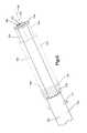
- the outer tube 110preferably also includes a pair of diametrically opposed slots 120 extending from the distal end 116 of the outer tube 110 such that when the outer tube 110 is coupled to the body portion 20 of the bone fixation element 10, the diametrically opposed slots 120 align with the rod-receiving channel 26 formed in the bone fixation element 10 so that the spinal rod 45 can pass from the reduction tool 100 into the rod-receiving channel 26.
- the diametrically opposed slots 120preferably extend approximately halfway between the distal end 116 and the proximal end 114.
- the distal end 116 of the outer tube 110preferably includes an engagement feature 130 for engaging a corresponding feature 31 formed on the outer surface of the body portion 20 of the bone fixation element 10.
- the engagement feature 130can be any feature or element now or hereafter known in the art including, for example, threads, etc.
- the outer tube 110includes one or more projections for mating with one or more shoulders or recesses formed on the outer surface of the body portion 20, or vice versa.
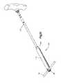
- the outer tube 110preferably also includes a pivot point 135. More preferably, the outer tube 110 includes a pivot point 135 disposed at approximately a half way point between the proximal and distal ends 114, 116 of the outer tube 110. The pivot point 135 is preferably located between the diametrically opposed slots 120 extending from the distal end 116 of the outer tube 110 and the diametrically opposed guide slots 140 extending from the proximal end 114 of the outer tube 110, as will be described in greater detail below.
- the pivot points 135serve as a fulcrum about which an inwardly applied force to the proximal end 114 of the outer tube 110 across the guide slots 140 is transmitted as an outwardly spreading force to the distal end 116 of the outer tube 110 across the diametrically opposed slots 120 so that the engagement features 130 formed on the distal end 116 of the outer tube 110 can surround and engage the corresponding features 31 disposed on the outer surface of the body portion 20 of the bone fixation element 10. That is, in use, the surgeon preferably applies an inwardly directed force to the proximal end 114 of the outer tube 110 thereby at least partially closing the guide slots 140 extending from the proximal end 114 of the outer tube 110.
- the inwardly directed forceis transmitted through the pivot points 135 or fulcrum resulting in an outwardly spreading force to the distal end 116 of the outer tube 110 so that the distal end 116 of the outer tube 110 can surround and engage the body portion 20 of the bone fixation element 10. More specifically, to allow the distal end 116 of the outer tube 110 to spread open so that the engagement features 130 ( e . g ., projections, etc .) formed on the distal end 116 of the outer tube 110 can engage the features 31 (e.g., recess, etc.) formed on the outer surface of the body portion 20 on the bone fixation element 10.
- the engagement features 130e . g ., projections, etc .
- Removal of the inwardly directed force at the proximal end 114 of the outer tube 110preferably results in the automatic closing of the distal end 116 of the outer tube 110 and the engagement of the engagement features 130 formed on the outer tube 110 to the features 31 formed on the bone fixation element 10.
- the distal end 116 of the outer tube 110can be sized and configured to snap over the body portion 20 as a result of the flexibility allowed by the diametrically opposed slots 120 and the engagement features 130 can couple to features 31 as a result thereof.
- the outer tube 110preferably also includes one or more guide recesses 145 formed in an inner surface of the outer tube 110. More preferably, the outer tube 110 includes a pair of diametrically opposed guide recesses 145.
- the guide recesses 145preferably extend from the proximal end 114 of the outer tube 110 parallel to the longitudinal axis 112.
- the guide recesses 145are sized and configured to mate with one or more protrusions 162 formed on an outer surface 151 of the inner tube 150 and with one or more cantilever engagement members 170, as will be described in greater detail below.
- the outer tube 110preferably also includes one or more guide slots 140, and more preferably a pair of diametrically opposed guide slots 140 disposed in the outer surface of the outer tube 110 and extending from the proximal end 114 along the longitudinal axis 112 for receiving and guiding one or more pins 177 protruding from an outer surface 151 of the inner tube 150, as will be described in greater detail below.
- the diametrically opposed guide slots 140are preferably aligned with the pair of diametrically opposed slots 120 but separated therefrom via the pivot points 135 or fulcrum on either side of the outer tube 110.
- each guide slot 140is preferably parallel to and collinear with a longitudinal axis of each slot 120. Furthermore, the pair of diametrically opposed guide slots 140 are preferably aligned with and overlapping with the pair of diametrically opposed guide recesses 145.
- the outer tube 110also preferably includes a pin stop 148 at the distal end of the guide slots 140, which is preferably located near or proximal to the halfway point between the proximal and distal ends 114, 116.
- the pin stop 148extends transversely through the outer tube 110 and is sized and configured to contact the one or more pins 177 protruding from the outer surface 151 of the inner tube 150 to prevent over advancement of the inner tube 150 with respect to the outer tube 110, as will be described in greater detail below.
- the pin stop 148may be nothing more than the pivot pin point so that over advancement of the inner tube 150 with respect to the outer tube 110 is prevented by the pin stop 148 contacting the pivot point 135.
- the pin stop 148may be a surface separate and distinct from the pivot point 135.
- the inner tube 150includes a longitudinal axis 152, a proximal end 154, a distal end 156 and a lumen 158 extending from the proximal end 154 to the distal end 156.
- the inner tube 150also includes one or more engagement features 160 at or near the distal end 156 of the inner tube 150 for engaging the locking cap 40 of the bone fixation element 10.
- the engagement feature 160may be any feature now or hereafter known for coupling the locking cap 40 to the distal end 156 of the inner tube 150.
- the distal end 156 of the inner tube 150may include a pair of protrusions 162 formed on an outer surface 151 of the inner tube 150.
- the protrusions 162incorporating and/or separated by a channel 164 for engaging a cantilever engagement member 170.
- the cantilever engagement members 170are preferably sized and configured to extend beyond the distal end 156 of the inner tube 150 and to snap lock over the locking cap 40 by aligning the cantilever engagement member 170 over the locking cap 40 and applying a downward force. That is, an interior surface of the cantilever engagement member 170 may be sized and configured to snap lock over an external surface of the locking cap 40 for securely coupling the locking cap 40 to the distal end 156 of the inner tube 150.
- the protrusions 162 and cantilever engagement member 170are slidably received within the guide recesses 145 formed in the inner surface of the outer tube 110.
- the proximal end 154 of the inner tube 150is operatively coupled to the rotatable sleeve 180.
- the rotatable sleeve 180is preferably disposed about the inner tube 150. That is, the inner tube 150 is preferably disposed within a lumen 188 formed in the rotatable sleeve 180, as will be described in greater detail below.
- the inner tube 150is coupled to the rotatable sleeve 180 such that rotation of the rotatable sleeve 180 about the longitudinal axis 152 of the inner tube 150 does not rotate the inner tube 150.
- the inner tube 150does not rotate while the surgeon is rotating the rotatable sleeve 180.
- the outer surface 151 of the inner tube 150preferably includes a shoulder or lip 175 formed thereon for reasons described below.
- the rotatable sleeve 180includes a longitudinal axis 182, a proximal end 184, a distal end 186 and a lumen 188 extending from the proximal end 184 to the distal end 186.
- the rotatable sleeve 180preferably also includes an engagement feature 189 disposed adjacent to or at the proximal end 184 thereof to enable the surgeon to impart a rotational force to the rotatable sleeve 180.
- the engagement feature 189can be any feature known in the art including but not limited to, an external hex, an internal hex, threads, etc.
- the distal end 186 of the rotatable sleeve 180preferably terminates adjacent to and preferably contacts the shoulder or lip 175 formed on the outer surface 151 of the inner tube 150 when the rotatable sleeve 180 is disposed over the outer surface 151 of the inner tube 150.
- Threading 190is disposed on the outer surface 181 of the rotatable sleeve 180. The threading 190 preferably extends from the distal end 186 of the rotatable sleeve 180.
- the threading 190is sized and configured to engage corresponding threading (not shown) formed on the inner surface, preferably adjacent to the proximal end 114, of the outer tube 110 when the inner tube 150 and the rotatable sleeve 180 are disposed within the lumen 118 formed in the outer tube 110.
- an exemplary method of using the reduction tool 100will now be described.
- An incisionis made in the patient as required.
- two or more bone fixation elements 10are implanted into the patient's vertebrae, as required, through the incision.
- the distal end 116 of the outer tube 110is coupled to each of the pre-implanted body portions 20 of the bone fixation elements 10, as previously described.
- the outer tubes 110may be coupled to the bone fixation elements 10 prior to the bone fixation elements 10 being implanted into the patient's vertebrae.
- the distal end 156 of the inner tubes 150are coupled to the locking caps 40 as previously described.
- the spinal rod 45is inserted through the diametrically opposed slots 120 extending from the distal end 116 of the outer tubes 110, transversely to the longitudinal axis 112 of the outer tubes 110.
- the spinal rod 45may be inserted through the diametrically opposed slots 120 prior to the locking caps 40 being coupled to the inner tubes 150.
- the inner tube 150 with the locking cap 40 coupled theretoare then inserted into the lumen 118 formed in the outer tube 110.
- the inner tube 150is slidably advanced within the lumen 118 of the outer tube 150 until the external threading 190 formed on the outer surface 181 of the rotatable sleeve 180 engages corresponding threads formed on the inner surface of the outer tube 110, at which point further advancement of the inner tube 150 with respect to the outer tube 110 occurs via a rotational force that is imparted to the rotatable sleeve 180 via, for example, the engagement feature 189 formed at the proximal end 184 of the rotatable sleeve 180.
- Advancement of the inner tube 150 with respect to the outer tube 110 resulting from the rotation of the rotatable sleeve 180causes the distal end 186 of the rotatable sleeve 180 to impart a force to the shoulder or lip 175 formed on the outer surface 151 of the inner tube 150, which in turn, causes non-rotational, advancement of the inner tube 150 with respect to the outer tube 110.
- Thisadvances the locking cap 40 coupled to the distal end 156 of the inner tube 150 into contact with the spinal rod 45, which in turn, advances the spinal rod 45 into the rod-receiving channel 26 formed in the body portion 20 of the bone fixation element 10.
- advancement of the inner tube 150 with respect to the outer tube 110provisionally couples the locking cap 40 to the body portion 20 of the bone fixation element 10 thereby retaining the spinal rod 45 within the rod-receiving channel 26.
- Over advancement of the locking cap 40 and the spinal rod 45 with respect to the body portion 20is prevented by the engagement of the pin 177 extending from the outer surface 151 of the inner tube 150 with the pin stop 148 formed in the outer tube 110.
- Final securement of the locking cap 40 to the body portion 20 and securement of the spinal rod 45 within the rod-receiving channel 26 of the bone fixation element 10may be achieved by a drive tool 200, such as a screw driver, a star drive, a hex drive, etc ., inserted through the lumens 188, 158, 118 formed in the rotatable sleeve 180, inner tube 150 and outer tube 110, respectively.
- Rotation of the drive tool 200preferably secures the locking cap 40 to the body portion 20 of the bone fixation element 10 as well as decouples the inner tube 150 from the locking cap 40.
- the drive tool 200 and the inner tube 150are then removed and the outer tube 110 is decoupled from the body portion 20 by, for example, imparting a force to the proximal end 114 of the outer tube 110 as discussed above. Leaving the spinal rod 45 secured within the rod-receiving channel 26 formed in the bone fixation element 10, which is secured to the patient's bone.
Landscapes
- Health & Medical Sciences (AREA)
- Orthopedic Medicine & Surgery (AREA)
- Neurology (AREA)
- Life Sciences & Earth Sciences (AREA)
- Surgery (AREA)
- Engineering & Computer Science (AREA)
- Biomedical Technology (AREA)
- General Health & Medical Sciences (AREA)
- Veterinary Medicine (AREA)
- Heart & Thoracic Surgery (AREA)
- Public Health (AREA)
- Animal Behavior & Ethology (AREA)
- Molecular Biology (AREA)
- Medical Informatics (AREA)
- Nuclear Medicine, Radiotherapy & Molecular Imaging (AREA)
- Cardiology (AREA)
- Oral & Maxillofacial Surgery (AREA)
- Transplantation (AREA)
- Vascular Medicine (AREA)
- Surgical Instruments (AREA)
- Prostheses (AREA)
Description
- The present invention relates generally to orthopedics. More specifically, the present invention relates to a reduction tool and associated method for facilitating insertion of a longitudinal spinal rod into a rod-receiving channel formed in a bone fixation element.
- Spinal fixation systems which are used to correct spinal deformities and treat spinal degenerations generally include a plurality of bone fixation elements anchored in, for example, the pedicle of adjacent vertebrae. The bone fixation elements are interconnected to one another by, for example, one or more elongated spinal rods. In order to access the spinal area for implantation of these spinal fixation systems and their individual components, open approach surgical techniques have traditionally been employed. These open procedures generally involve large skin incisions and extensive tissue retraction and resection, all which may result in considerable post-operative pain and prolonged recovery time.
- More recently, surgeons have used minimally invasive techniques to reduce the post-operative effects of spinal fixation procedures. A paraspinal approach is one form of minimally invasive technique and involves muscle splitting or muscle sparing in order to gain access to the posterior elements of the spine. Such a technique minimizes trauma to tissues adjacent the spine. Unlike open procedures where muscles and other soft tissue are cut, split, stripped and dissected, the paraspinal approach involves separation or splitting of the muscles along their fibers.
- Implanting a spinal rod fixation system generally involves at least two steps: (i) placing bone fixation elements into the spine and (ii) inserting a rod between the bone fixation elements. Bone fixation elements generally include a screw portion and a body portion. The screw portion is inserted into the spine and the body portion generally includes a rod-receiving channel for receiving and securing the spinal rod. The rod may be inserted through an incision in the skin, which may be separate and distinct from the incision through which the bone fixation element(s) is placed. Alternatively, the rod may be inserted through the same incision as the bone fixation element(s).
- It is desirable to have a minimally invasive bone fixation element and rod introduction system which minimizes trauma to the body, provides for simplified and time saving instrumentation for rod reduction, enables a rod to be readily connected to multiple bone fixation elements anchored at varying depths in the body, is generally simple to use, enhances direct visualization of the rod as the rod is being inserted into the bone fixation elements and facilitates securement of the rod to the bone fixation elements.
US 2005/0149036 A1 discloses an instrument for engaging a bone fixation element, comprising an outer tube having an engagement feature for engaging the body portion of a bone fixation element. The instrument further comprises an inner tube having an engagement member for engaging a locking cap of the bone fixation element. A threaded outer surface of the inner tube engages a threaded inner surface of the outer tube when the inner tube is slidably disposed within the outer tube.- The present invention is directed to a reduction tool according to
claim 1. It can be used for posterior spinal fixation to facilitate insertion of a longitudinal spinal rod into a rod-receiving channel formed in a bone fixation element. The reduction tool includes an outer tube, an inner tube and a rotatable sleeve. The outer tube is preferably sized and configured to transversely receive the spinal rod therethrough and is operatively coupled to the bone fixation element. The inner tube is operatively coupled to a locking cap and is slidably disposed within the outer tube. The rotatable sleeve is operatively associated with the inner tube and the outer tube such that rotation of the sleeve moves the inner tube with respect to the outer tube thereby advancing the spinal rod into the rod-receiving channel formed in the bone fixation element and thereby coupling the locking cap to the bone fixation element to secure the rod to the bone fixation element. - The reduction tool includes an outer tube, an inner tube and a rotatable sleeve. The outer tube includes a proximal end, a distal end and a lumen defining an inner surface, the lumen extending from the proximal end to the distal end. The distal end including an engagement feature for engaging a body portion of a bone fixation element. The inner surface including a plurality of threads. The inner tube includes a proximal end, a distal end and a lumen extending from the proximal end to the distal end, the inner tube being slidably disposed within the lumen formed in the outer tube. The distal end of the inner tube including an engagement member for engaging a locking cap. The rotatable sleeve including a proximal end, a distal end and a lumen extending from the proximal end to the distal end, the rotatable sleeve being rotatably coupled to the proximal end of the inner tube. The rotatable sleeve further including a plurality of external threads for threadably engaging the threads formed on the inner surface of the outer tube such that rotation of the sleeve advances the inner tube with respect to the outer tube and hence downwardly and non-rotationally forces the locking cap and the elongated spinal rod into engagement with the body portion of the bone fixation element to provisionally lock the locking cap to the body portion of the bone fixation element and thus secure the spinal rod within the rod-receiving channel formed in the body portion of the bone fixation element.
- The outer tube preferably also includes a pair of diametrically opposed slots extending from the distal end of the outer tube such that when the outer tube is engaged to the body portion of the bone fixation element, the diametrically opposed slots align with the rod-receiving channel formed in the bone fixation element. The diametrically opposed slots being sized and configured to enable the elongated spinal rod to transversely extend therethrough. The outer tube preferably also includes a pair of diametrically opposed guide slots extending from the proximal end of the outer tube for receiving one or more pins protruding from an outer surface of the inner tube. The guide slots being substantially aligned with the diametrically opposed slots extending from the distal end of the outer tube. The outer tube preferably also includes a pivot point located longitudinally between each of the diametrically opposed slots extending from the distal end of the outer tube and each of the diametrically opposed guide slots extending from the proximal end of the outer tube so that the distal end of the outer tube can be spread apart to facilitate engagement with the body portion of the bone fixation element. The outer tube may also include one or more guide recesses formed in the inner surface of the outer tube, the guide recesses extending from the proximal end of the outer tube. The guide recesses slidably receiving the engagement feature formed on the inner tube.
- In one exemplary method of use, the surgeon preferably forms an incision at a desired location in a patient to access the patient's bones, for example, to access adjacent vertebral bodies. Next, the surgeon implants two or more bone fixation elements into the patient's bones through the incision, for example, the surgeon may insert one bone fixation element into each of the adjacent vertebral bodies. The outer tube of one of the reduction tools is then coupled to each of the pre-implanted bone fixation elements. The spinal rod is then transversely inserted through each of the outer tubes. The surgeon then inserts one of the inner tubes with the locking cap coupled thereto into each of the lumens formed in the outer tubes until the threads formed on the rotatable sleeves engage the corresponding threads formed on the outer tubes. The surgeon then rotates the rotatable sleeve to further advance the inner tubes with respect to the outer tubes until the spinal rod is seated within the rod-receiving channels formed in the body portions of the bone fixation elements and the locking caps engage the body portions of the bone fixation elements.
- The foregoing summary, as well as the following detailed description of the preferred embodiments of the application, will be better understood when read in conjunction with the appended drawings. For the purposes of illustrating the reduction tool and associated method of use, there is shown in the drawings a preferred embodiment. It should be understood, however, that the application is not limited to the precise arrangements and instrumentalities shown. In the drawings:
Fig. 1 is a perspective view of an exemplary, prior art bone fixation element;Fig. 2 is a cross-sectional view of the bone fixation element shown inFig. 1 ;Fig. 3 illustrates an exploded, perspective view of a preferred embodiment of a reduction tool in accordance with the present invention, the reduction tool including an outer tube, an inner tube and a rotatable sleeve, the outer tube being operatively coupled to a body portion of the bone fixation element shown inFig. 1 and illustrating an unreduced spinal rod extending transversely through the outer tube;Fig. 4 illustrates a perspective view of the outer tube shown inFig. 3 , the outer tube being decoupled from the body portion of the bone fixation element shown inFig. 1 and including an unreduced spinal rod extending therethrough;Fig. 5 illustrates an alternate perspective view of the outer tube shown inFig. 3 , the outer tube being operatively coupled to the body portion of the bone fixation element shown inFig. 1 and including an unreduced spinal rod extending therethrough;Fig. 6 illustrates a side view of the outer tube shown inFig. 3 , the outer tube being decoupled from the body portion of the bone fixation element shown inFig. 1 and including an unreduced spinal rod extending therethrough;Fig. 7 illustrates an alternate side view of the outer tube shown inFig. 3 , the outer tube being decoupled from the body portion of the bone fixation element shown inFig. 1 and including an unreduced spinal rod extending therethrough, a proximal end of the outer tube being subjected to a force to expand a distal end of the outer tube;Fig. 8 illustrates a detailed, perspective view of a proximal end of the outer tube decoupled from a distal end of the inner tube;Fig. 8A illustrates a detailed view of an exemplary, partial embodiment of a locking cap engagement feature formed on the distal end of the inner tube for coupling the locking cap to the inner tube;Fig. 9 illustrates a detailed, perspective view of the distal end of the inner tube being slidably received within a lumen formed in the proximal end of the outer tube;Fig. 10 illustrates a side view of the rotatable sleeve coupled to the proximal end of the inner tube;Fig. 11 illustrates a perspective view of the reduction tool shown inFig. 3 during reduction of the spinal rod, the reduction tool being coupled to the body portion of the bone fixation element shown inFig. 1 and including a spinal rod extending transversely therethrough;Fig. 12 illustrates a perspective view of the reduction tool shown inFig. 3 after reduction of the spinal rod into the rod-receiving channel formed in the bone fixation element and provisional locking of the locking cap to the body portion;Fig. 13 illustrates a perspective view of the reduction tool shown inFig. 12 in combination with an exemplary drive tool;Fig. 14 illustrates a perspective view of the reduction tool shown inFig. 12 during final securement of the locking cap to the bone fixation element using the driver tool shown inFig. 13 ; andFig. 15 illustrates an exploded, perspective view of the reduction tool and drive tool shown inFig. 14 subsequent to final securement of the locking cap to the body portion of the bone fixation element and during removal of the outer tube, inner tube, rotatable sleeve and drive tool.- Certain terminology is used in the following description for convenience only and is not limiting. The words "right", "left", "lower" and "upper" designate directions in the drawings to which reference is made. The words "inwardly" or "distally" and "outwardly" or "proximally" refer to directions toward and away from, respectively, the geometric center of the reduction tool and related parts thereof. The words, "anterior", "posterior", "superior", "inferior" and related words and/or phrases designate preferred positions and orientations in the human body to which reference is made and are not meant to be limiting. The terminology includes the above-listed words, derivatives thereof and words of similar import.
- An exemplary embodiment of the invention will now be described with reference to the drawings. In general, such embodiment relates to a
reduction tool 100, by way of non-limiting example, areduction tool 100 for use in posterior spinal fixation to facilitate insertion of a longitudinalspinal rod 45 into a rod-receivingchannel 26 formed in abone fixation element 10. The invention may have other applications and uses and should not be limited to the structure or use described and illustrated. - As will be described in greater detail below, the
reduction tool 100 preferably includes anouter tube 110 sized and configured to transversely receive thespinal rod 45 therethrough, theouter tube 110 being operatively coupled to thebone fixation element 10, aninner tube 150 operatively coupled to alocking cap 40 and slidably disposed within theouter tube 110, and arotatable sleeve 180 for rotatably advancing theinner tube 150 with respect to theouter tube 110 to advance thespinal rod 45 into the rod-receivingchannel 26 formed in thebone fixation element 10 and to couple the lockingcap 40 to thebone fixation element 10 to secure therod 45 to thebone fixation element 10. - While the
reduction tool 100 will be described as and may generally be used in the spine (for example, in the lumbar, thoracic or cervical regions), those skilled in the art will appreciate that thereduction tool 100 may be used for fixation of other parts of the body such as, for example, joints, long bones or bones in the hand, face, feet, extremities, cranium,etc. - As previously mentioned and as will be described in greater detail below, the
reduction tool 100 may be used to facilitate insertion of the longitudinalspinal rod 45 into the rod-receivingchannel 26 formed in thebone fixation element 10. It should be understood that thespinal rod 45 may include, but not limited to, a solid rod, a non-solid rod, a flexible or dynamic rod,etc. It should be understood that thereduction tool 100 is not limited in use to any particular type ofspinal rod 45. - In addition, as generally understood by one of ordinary skill in the art, it should be understood that
bone fixation element 10 is used generally and may include, but are not limited to, poly-axial or mono-axial pedicle screws, hooks (both mono-axial and poly-axial) including pedicle hooks, transverse process hooks, sublaminar hook, or other fasteners, clamps or implants. - Referring to
Figs. 1 and2 , an exemplarybone fixation element 10 is shown. Thebone fixation element 10 may include a bone anchor 12 (shown as a bone screw) having an enlarged, spherically-shapedhead portion 14, a body portion 20 (shown as a top loading body portion) having anupper end 22, alower end 24, a rod-receiving channel 26 (shown as a top loading U-shaped rod-receiving channel) defining a pair of spaced apartarms sleeve 35 and acollet 36 slidably disposed within thebody portion 20, at least a portion of thecollet 36 being slidably disposed within thesleeve 35, and a lockingcap 40 such as, for example, a set screw or a partial turn closure cap such as, for example, a quarter-turn closure cap or cam lock. In use, theenlarged head portion 14 of thebone anchor 12 may be separate from and be disposed within thelower end 24 of thebody portion 20 so that thebone anchor 12 can poly-axial rotate with respect to thebody portion 20. Alternatively, thebone anchor 12 may be formed integral with thebody portion 20 to form a monolithic structure which is sometimes referred to as a mono-axial pedicle screw or hook. - Once the
spinal rod 45 is inserted into the rod-receivingchannel 26, the surgeon can secure the position of therod 45 with respect to thebody portion 20 and the position of thebone anchor 12 with respect to thebody portion 20 by, for example, rotating the lockingcap 40. Rotation of the lockingcap 40 preferably causes the lockingcap 40 to exert a downward force onto thespinal rod 45, which is received within the rod-receivingchannel 26, which, in turn, causes therod 45 to exert a downward force onto thesleeve 35 with causes thesleeve 35 to move with respect to thecollet 36, which in turn causes thecollet 36 to compress around theenlarged head portion 14 of thebone anchor 12 thereby securing the position of thebone anchor 12 with respect to thebody portion 20. In addition, rotation of the lockingcap 40 may cause thespinal rod 45 to be sandwiched in-between the lockingcap 40 and thesleeve 35 thereby securing the position of therod 45 with respect to thebody portion 20. It should be understood however that thereduction tool 100 is not limited in use to any particular type ofbone fixation element 10. - Exemplary embodiments of
bone fixation elements 10 include those described inWO 2009/015100 A2 ,WO 2006/116437 A2 WO 1998/052 482 A1 . It should be understood however that the present invention is not limited in use to any particular type ofbone fixation element 10. - Referring to
Fig. 3 , thereduction tool 100 includes anouter tube 110, aninner tube 150 and arotatable sleeve 180. Theouter tube 110 is operably coupled to theinner tube 150, which is operatively coupled to therotatable sleeve 180. More preferably, at least a portion of theinner tube 150 is slidably received within theouter tube 110 and at least a portion of theinner tube 150 is disposed within therotatable sleeve 180 so that therotatable sleeve 180 can operatively engage theouter tube 110 after theinner tube 150 has been advanced a sufficient distance into theouter tube 150, as will be described in greater detail below. - Referring to
Figs. 3-7 , theouter tube 110 includes alongitudinal axis 112, aproximal end 114, adistal end 116 and alumen 118 extending from theproximal end 114 to thedistal end 116. Theouter tube 110 preferably also includes a pair of diametricallyopposed slots 120 extending from thedistal end 116 of theouter tube 110 such that when theouter tube 110 is coupled to thebody portion 20 of thebone fixation element 10, the diametricallyopposed slots 120 align with the rod-receivingchannel 26 formed in thebone fixation element 10 so that thespinal rod 45 can pass from thereduction tool 100 into the rod-receivingchannel 26. As shown, the diametricallyopposed slots 120 preferably extend approximately halfway between thedistal end 116 and theproximal end 114. - The
distal end 116 of theouter tube 110 preferably includes anengagement feature 130 for engaging acorresponding feature 31 formed on the outer surface of thebody portion 20 of thebone fixation element 10. Theengagement feature 130 can be any feature or element now or hereafter known in the art including, for example, threads,etc. Preferably however theouter tube 110 includes one or more projections for mating with one or more shoulders or recesses formed on the outer surface of thebody portion 20, or vice versa. - The
outer tube 110 preferably also includes apivot point 135. More preferably, theouter tube 110 includes apivot point 135 disposed at approximately a half way point between the proximal anddistal ends outer tube 110. Thepivot point 135 is preferably located between the diametricallyopposed slots 120 extending from thedistal end 116 of theouter tube 110 and the diametricallyopposed guide slots 140 extending from theproximal end 114 of theouter tube 110, as will be described in greater detail below. The pivot points 135 serve as a fulcrum about which an inwardly applied force to theproximal end 114 of theouter tube 110 across theguide slots 140 is transmitted as an outwardly spreading force to thedistal end 116 of theouter tube 110 across the diametricallyopposed slots 120 so that the engagement features 130 formed on thedistal end 116 of theouter tube 110 can surround and engage the corresponding features 31 disposed on the outer surface of thebody portion 20 of thebone fixation element 10. That is, in use, the surgeon preferably applies an inwardly directed force to theproximal end 114 of theouter tube 110 thereby at least partially closing theguide slots 140 extending from theproximal end 114 of theouter tube 110. The inwardly directed force is transmitted through the pivot points 135 or fulcrum resulting in an outwardly spreading force to thedistal end 116 of theouter tube 110 so that thedistal end 116 of theouter tube 110 can surround and engage thebody portion 20 of thebone fixation element 10. More specifically, to allow thedistal end 116 of theouter tube 110 to spread open so that the engagement features 130 (e.g., projections,etc.) formed on thedistal end 116 of theouter tube 110 can engage the features 31 (e.g., recess, etc.) formed on the outer surface of thebody portion 20 on thebone fixation element 10. Removal of the inwardly directed force at theproximal end 114 of theouter tube 110 preferably results in the automatic closing of thedistal end 116 of theouter tube 110 and the engagement of the engagement features 130 formed on theouter tube 110 to thefeatures 31 formed on thebone fixation element 10. - It should be noted that it is not necessary for an inwardly directed force to be applied to the
proximal end 114 of theouter tube 110 for theouter tube 110 to engage thebody portion 20; instead, thedistal end 116 of theouter tube 110 can be sized and configured to snap over thebody portion 20 as a result of the flexibility allowed by the diametricallyopposed slots 120 and the engagement features 130 can couple tofeatures 31 as a result thereof. - Referring to
Figs. 8 and9 , theouter tube 110 preferably also includes one or more guide recesses 145 formed in an inner surface of theouter tube 110. More preferably, theouter tube 110 includes a pair of diametrically opposed guide recesses 145. The guide recesses 145 preferably extend from theproximal end 114 of theouter tube 110 parallel to thelongitudinal axis 112. The guide recesses 145 are sized and configured to mate with one ormore protrusions 162 formed on anouter surface 151 of theinner tube 150 and with one or morecantilever engagement members 170, as will be described in greater detail below. - In addition, referring to
Figs. 3-9 and as previously mentioned, theouter tube 110 preferably also includes one ormore guide slots 140, and more preferably a pair of diametricallyopposed guide slots 140 disposed in the outer surface of theouter tube 110 and extending from theproximal end 114 along thelongitudinal axis 112 for receiving and guiding one ormore pins 177 protruding from anouter surface 151 of theinner tube 150, as will be described in greater detail below. The diametricallyopposed guide slots 140 are preferably aligned with the pair of diametricallyopposed slots 120 but separated therefrom via the pivot points 135 or fulcrum on either side of theouter tube 110. That is, a longitudinal axis of eachguide slot 140 is preferably parallel to and collinear with a longitudinal axis of eachslot 120. Furthermore, the pair of diametricallyopposed guide slots 140 are preferably aligned with and overlapping with the pair of diametrically opposed guide recesses 145. - The
outer tube 110 also preferably includes apin stop 148 at the distal end of theguide slots 140, which is preferably located near or proximal to the halfway point between the proximal anddistal ends pin stop 148 extends transversely through theouter tube 110 and is sized and configured to contact the one ormore pins 177 protruding from theouter surface 151 of theinner tube 150 to prevent over advancement of theinner tube 150 with respect to theouter tube 110, as will be described in greater detail below. As shown, thepin stop 148 may be nothing more than the pivot pin point so that over advancement of theinner tube 150 with respect to theouter tube 110 is prevented by the pin stop 148 contacting thepivot point 135. Alternatively, thepin stop 148 may be a surface separate and distinct from thepivot point 135. - Referring to
Figs. 3 ,8 ,8a and9 , theinner tube 150 includes alongitudinal axis 152, aproximal end 154, adistal end 156 and alumen 158 extending from theproximal end 154 to thedistal end 156. Theinner tube 150 also includes one or more engagement features 160 at or near thedistal end 156 of theinner tube 150 for engaging the lockingcap 40 of thebone fixation element 10. Theengagement feature 160 may be any feature now or hereafter known for coupling the lockingcap 40 to thedistal end 156 of theinner tube 150. For example, thedistal end 156 of theinner tube 150 may include a pair ofprotrusions 162 formed on anouter surface 151 of theinner tube 150. Theprotrusions 162 incorporating and/or separated by achannel 164 for engaging acantilever engagement member 170. Thecantilever engagement members 170 are preferably sized and configured to extend beyond thedistal end 156 of theinner tube 150 and to snap lock over the lockingcap 40 by aligning thecantilever engagement member 170 over the lockingcap 40 and applying a downward force. That is, an interior surface of thecantilever engagement member 170 may be sized and configured to snap lock over an external surface of the lockingcap 40 for securely coupling the lockingcap 40 to thedistal end 156 of theinner tube 150. In use and as previously mentioned, theprotrusions 162 andcantilever engagement member 170 are slidably received within the guide recesses 145 formed in the inner surface of theouter tube 110. - Referring to
Figs. 3 and10 , theproximal end 154 of theinner tube 150 is operatively coupled to therotatable sleeve 180. Therotatable sleeve 180 is preferably disposed about theinner tube 150. That is, theinner tube 150 is preferably disposed within alumen 188 formed in therotatable sleeve 180, as will be described in greater detail below. Theinner tube 150 is coupled to therotatable sleeve 180 such that rotation of therotatable sleeve 180 about thelongitudinal axis 152 of theinner tube 150 does not rotate theinner tube 150. Theinner tube 150 does not rotate while the surgeon is rotating therotatable sleeve 180. Theouter surface 151 of theinner tube 150 preferably includes a shoulder orlip 175 formed thereon for reasons described below. - Referring to
Figs. 3 and10 , therotatable sleeve 180 includes alongitudinal axis 182, aproximal end 184, adistal end 186 and alumen 188 extending from theproximal end 184 to thedistal end 186. Therotatable sleeve 180 preferably also includes anengagement feature 189 disposed adjacent to or at theproximal end 184 thereof to enable the surgeon to impart a rotational force to therotatable sleeve 180. Theengagement feature 189 can be any feature known in the art including but not limited to, an external hex, an internal hex, threads,etc. Thedistal end 186 of therotatable sleeve 180 preferably terminates adjacent to and preferably contacts the shoulder orlip 175 formed on theouter surface 151 of theinner tube 150 when therotatable sleeve 180 is disposed over theouter surface 151 of theinner tube 150.Threading 190 is disposed on theouter surface 181 of therotatable sleeve 180. The threading 190 preferably extends from thedistal end 186 of therotatable sleeve 180. The threading 190 is sized and configured to engage corresponding threading (not shown) formed on the inner surface, preferably adjacent to theproximal end 114, of theouter tube 110 when theinner tube 150 and therotatable sleeve 180 are disposed within thelumen 118 formed in theouter tube 110. - Referring to
Figs. 11-15 , an exemplary method of using thereduction tool 100 will now be described. An incision is made in the patient as required. Preferably, two or morebone fixation elements 10 are implanted into the patient's vertebrae, as required, through the incision. Thedistal end 116 of theouter tube 110 is coupled to each of thepre-implanted body portions 20 of thebone fixation elements 10, as previously described. Alternatively, theouter tubes 110 may be coupled to thebone fixation elements 10 prior to thebone fixation elements 10 being implanted into the patient's vertebrae. Thedistal end 156 of theinner tubes 150 are coupled to the locking caps 40 as previously described. Thespinal rod 45 is inserted through the diametricallyopposed slots 120 extending from thedistal end 116 of theouter tubes 110, transversely to thelongitudinal axis 112 of theouter tubes 110. Alternatively, thespinal rod 45 may be inserted through the diametricallyopposed slots 120 prior to the locking caps 40 being coupled to theinner tubes 150. Theinner tube 150 with the lockingcap 40 coupled thereto are then inserted into thelumen 118 formed in theouter tube 110. Theinner tube 150 is slidably advanced within thelumen 118 of theouter tube 150 until theexternal threading 190 formed on theouter surface 181 of therotatable sleeve 180 engages corresponding threads formed on the inner surface of theouter tube 110, at which point further advancement of theinner tube 150 with respect to theouter tube 110 occurs via a rotational force that is imparted to therotatable sleeve 180 via, for example, theengagement feature 189 formed at theproximal end 184 of therotatable sleeve 180. - Advancement of the
inner tube 150 with respect to theouter tube 110 resulting from the rotation of therotatable sleeve 180 causes thedistal end 186 of therotatable sleeve 180 to impart a force to the shoulder orlip 175 formed on theouter surface 151 of theinner tube 150, which in turn, causes non-rotational, advancement of theinner tube 150 with respect to theouter tube 110. This in turn advances the lockingcap 40 coupled to thedistal end 156 of theinner tube 150 into contact with thespinal rod 45, which in turn, advances thespinal rod 45 into the rod-receivingchannel 26 formed in thebody portion 20 of thebone fixation element 10. In addition, advancement of theinner tube 150 with respect to theouter tube 110 provisionally couples the lockingcap 40 to thebody portion 20 of thebone fixation element 10 thereby retaining thespinal rod 45 within the rod-receivingchannel 26. Over advancement of the lockingcap 40 and thespinal rod 45 with respect to thebody portion 20 is prevented by the engagement of thepin 177 extending from theouter surface 151 of theinner tube 150 with the pin stop 148 formed in theouter tube 110. - Final securement of the locking
cap 40 to thebody portion 20 and securement of thespinal rod 45 within the rod-receivingchannel 26 of thebone fixation element 10 may be achieved by adrive tool 200, such as a screw driver, a star drive, a hex drive,etc., inserted through thelumens rotatable sleeve 180,inner tube 150 andouter tube 110, respectively. Rotation of thedrive tool 200 preferably secures the lockingcap 40 to thebody portion 20 of thebone fixation element 10 as well as decouples theinner tube 150 from the lockingcap 40. Thedrive tool 200 and theinner tube 150 are then removed and theouter tube 110 is decoupled from thebody portion 20 by, for example, imparting a force to theproximal end 114 of theouter tube 110 as discussed above. Leaving thespinal rod 45 secured within the rod-receivingchannel 26 formed in thebone fixation element 10, which is secured to the patient's bone. - It will be appreciated by those skilled in the art that changes could be made to the embodiments described above without departing from the broad inventive concept thereof. It is understood, therefore, that this invention is not limited to the particular embodiments disclosed, but it is intended to cover modifications within the scope of the present invention as defined by the appended claims
Claims (13)
- A rod-reduction and locking cap advancement tool (100) for reducing an elongated spinal rod (45) into a rod-receiving channel (26) formed in a body portion (20) of a bone fixation element (10) and for engaging a locking cap (40) to the body portion (20), the tool (100) comprising:an outer tube (110) including a proximal end (114), a distal end (116) and a lumen (118) defining an inner surface, the lumen (118) extending from the proximal end (114) to the distal end (116), the distal end (116) including an engagement feature (130) for engaging the body portion (20) of the bone fixation element (10), the inner surface including a plurality of threads; andan inner tube (150) including a proximal end (154), a distal end (156) and a lumen (158) extending from the proximal end (154) to the distal end (156), the inner tube (150) being slidably disposed within the lumen (118) formed in the outer tube (110), the distal end (156) of the inner tube (150) including an engagement member (160) for engaging the locking cap (40);characterized in that the tool (100) further comprises:a rotatable sleeve (180) including a proximal end (184), a distal end (186) and a lumen (188) extending from the proximal end (184) to the distal end (186), the rotatable sleeve (180) being rotatably coupled to the proximal end (154) of the inner tube (150), the sleeve (180) including a plurality of external threads (190) for threadably engaging the threads formed on the inner surface of the outer tube (110) such that rotation of the sleeve (180) advances the inner tube (150) with respect to the outer tube (110) and hence downwardly and non-rotationally forces the locking cap (40) and the elongated spinal rod (45) into engagement with the body portion (20) of the bone fixation element (10) to provisionally lock the locking cap (40) to the body portion (20) of the bone fixation element (10) and thus secure the spinal rod (45) within the rod-receiving channel (26) formed in the body portion (20) of the bone fixation element (10).
- The tool of claim 1, wherein the outer tube (110) further comprises:a pair of diametrically opposed slots (120) extending from the distal end (116) of the outer tube (110) such that when the outer tube (110) is engaged to the body portion (20) of the bone fixation element (10), the diametrically opposed slots (120) align with the rod-receiving channel (26) formed in the bone fixation element (10), the diametrically opposed slots (120) being sized and configured to enable the elongated spinal rod (45) to transversely extend therethrough;a pair of diametrically opposed guide slots (140) extending from the proximal end (114) of the outer tube (110) for receiving one or more pins (177) protruding from an outer surface (151) of the inner tube (150), the guide slots (140) being substantially aligned with the slots (120); anda pivot point (135) located longitudinally between each of the diametrically opposed slots (120) extending from the distal end (116) of the outer tube (110) and each of the diametrically opposed guide slots (140) extending from the proximal end (114) of the outer tube (110) so that the distal end (116) of the outer tube (110) can be spread apart to facilitate engagement with the body portion (20) of the bone fixation element (10).
- The tool of claim 2, wherein the pivot points (135) are located approximately half way between the proximal end (114) and the distal end (116) of the outer tube (110).
- The tool of claim 2 or 3, further comprising a pin stop (148) formed in the outer tube (110) for contacting the one or more pins (177) protruding from the outer surface (151) of the inner tube (150) to prevent over advancement of the inner tube (150) with respect to the outer tube (110).
- The tool of any one of claims 1 to 4, wherein the outer tube (110) further comprises one or more guide recesses (145) formed in the inner surface of the outer tube (110), the guide recesses (145) extending from the proximal end (114) of the outer tube (110).
- The tool of claim 5, wherein the inner tube (150) further comprises one or more protrusions (162) formed on an outer surface (151) thereof, the protrusions (162) being slidably received within the guide recesses (145).
- The tool of any one of claims 1 to 4, wherein the engagement feature (160) formed on the distal end (156) of the inner tube (150) includes a pair of protrusions (162) formed on an outer surface (151) of the inner tube (151), the protrusion (162) being spaced apart via a channel (164), the channel (164) being operatively coupled to an engagement member (170) for coupling the locking cap (40) to the inner tube (150).
- The tool of claim 7, wherein the pair of protrusions (162) and the engagement member (170) are slidably received within the one or more guide recesses (145) formed in the inner surface of the outer tube (110).
- The tool of any one of claims 1 to 8, wherein the rotatable sleeve (180) includes a lumen (188) for receiving at least a portion of the inner tube (150).
- The tool of any one of claims 1 to 9, wherein the rotatable sleeve (180) is operatively coupled to the inner tube (150) such that rotation of the rotatable sleeve (180) does not rotate the inner tube (150).
- The tool of claim 10, wherein the inner tube (150) further comprises a shoulder (175) formed on an outer surface (151) thereof for contacting the distal end (186) of the rotatable sleeve (180) when the rotatable sleeve (180) is disposed over the outer surface (151) of the inner tube (150).
- The tool of any one of claims 1 to 11, further comprising a drive tool (200) advancable through the lumens (118, 158, 188) formed in the outer tube (110), the inner tube (150) and the rotatable sleeve (180) so that the drive tool (200) engages the locking cap (40) to secure the locking cap (40) to the body portion (20) of the bone fixation element (10).
- The tool of any one of claims 1 to 12, wherein the sleeve (180) further comprises a distal instrument engagement feature (189) for imparting rotational force to the sleeve (180).
Applications Claiming Priority (2)
| Application Number | Priority Date | Filing Date | Title |
|---|---|---|---|
| US9661208P | 2008-09-12 | 2008-09-12 | |
| PCT/US2009/056706WO2010030916A2 (en) | 2008-09-12 | 2009-09-11 | Reduction tool |
Publications (2)
| Publication Number | Publication Date |
|---|---|
| EP2355732A2 EP2355732A2 (en) | 2011-08-17 |
| EP2355732B1true EP2355732B1 (en) | 2015-07-29 |
Family
ID=41821900
Family Applications (1)
| Application Number | Title | Priority Date | Filing Date |
|---|---|---|---|
| EP09792475.7AActiveEP2355732B1 (en) | 2008-09-12 | 2009-09-11 | Reduction tool for spinal rod |
Country Status (8)
| Country | Link |
|---|---|
| US (1) | US8317796B2 (en) |
| EP (1) | EP2355732B1 (en) |
| JP (1) | JP2012501809A (en) |
| KR (1) | KR20110068998A (en) |
| CN (1) | CN102149344A (en) |
| BR (1) | BRPI0916992A2 (en) |
| CA (1) | CA2736269A1 (en) |
| WO (1) | WO2010030916A2 (en) |
Families Citing this family (103)
| Publication number | Priority date | Publication date | Assignee | Title |
|---|---|---|---|---|
| US7833250B2 (en) | 2004-11-10 | 2010-11-16 | Jackson Roger P | Polyaxial bone screw with helically wound capture connection |
| US7862587B2 (en) | 2004-02-27 | 2011-01-04 | Jackson Roger P | Dynamic stabilization assemblies, tool set and method |
| US8876868B2 (en) | 2002-09-06 | 2014-11-04 | Roger P. Jackson | Helical guide and advancement flange with radially loaded lip |
| US7377923B2 (en) | 2003-05-22 | 2008-05-27 | Alphatec Spine, Inc. | Variable angle spinal screw assembly |
| US7766915B2 (en) | 2004-02-27 | 2010-08-03 | Jackson Roger P | Dynamic fixation assemblies with inner core and outer coil-like member |
| US8926670B2 (en) | 2003-06-18 | 2015-01-06 | Roger P. Jackson | Polyaxial bone screw assembly |
| US7776067B2 (en) | 2005-05-27 | 2010-08-17 | Jackson Roger P | Polyaxial bone screw with shank articulation pressure insert and method |
| US7967850B2 (en) | 2003-06-18 | 2011-06-28 | Jackson Roger P | Polyaxial bone anchor with helical capture connection, insert and dual locking assembly |
| US7179261B2 (en) | 2003-12-16 | 2007-02-20 | Depuy Spine, Inc. | Percutaneous access devices and bone anchor assemblies |
| US11419642B2 (en) | 2003-12-16 | 2022-08-23 | Medos International Sarl | Percutaneous access devices and bone anchor assemblies |
| US9451990B2 (en)* | 2004-02-17 | 2016-09-27 | Globus Medical, Inc. | Facet joint replacement instruments and methods |
| US7160300B2 (en) | 2004-02-27 | 2007-01-09 | Jackson Roger P | Orthopedic implant rod reduction tool set and method |
| JP2007525274A (en) | 2004-02-27 | 2007-09-06 | ロジャー・ピー・ジャクソン | Orthopedic implant rod reduction instrument set and method |
| US11241261B2 (en) | 2005-09-30 | 2022-02-08 | Roger P Jackson | Apparatus and method for soft spinal stabilization using a tensionable cord and releasable end structure |
| US8152810B2 (en) | 2004-11-23 | 2012-04-10 | Jackson Roger P | Spinal fixation tool set and method |
| US8926672B2 (en) | 2004-11-10 | 2015-01-06 | Roger P. Jackson | Splay control closure for open bone anchor |
| US9980753B2 (en) | 2009-06-15 | 2018-05-29 | Roger P Jackson | pivotal anchor with snap-in-place insert having rotation blocking extensions |
| US9168069B2 (en) | 2009-06-15 | 2015-10-27 | Roger P. Jackson | Polyaxial bone anchor with pop-on shank and winged insert with lower skirt for engaging a friction fit retainer |
| WO2006057837A1 (en) | 2004-11-23 | 2006-06-01 | Jackson Roger P | Spinal fixation tool attachment structure |
| US8444681B2 (en) | 2009-06-15 | 2013-05-21 | Roger P. Jackson | Polyaxial bone anchor with pop-on shank, friction fit retainer and winged insert |
| US7901437B2 (en) | 2007-01-26 | 2011-03-08 | Jackson Roger P | Dynamic stabilization member with molded connection |
| WO2007121271A2 (en) | 2006-04-11 | 2007-10-25 | Synthes (U.S.A) | Minimally invasive fixation system |
| CA2670988C (en) | 2006-12-08 | 2014-03-25 | Roger P. Jackson | Tool system for dynamic spinal implants |
| US8979904B2 (en) | 2007-05-01 | 2015-03-17 | Roger P Jackson | Connecting member with tensioned cord, low profile rigid sleeve and spacer with torsion control |
| US8439922B1 (en) | 2008-02-06 | 2013-05-14 | NiVasive, Inc. | Systems and methods for holding and implanting bone anchors |
| AU2010260521C1 (en) | 2008-08-01 | 2013-08-01 | Roger P. Jackson | Longitudinal connecting member with sleeved tensioned cords |
| WO2010030916A2 (en) | 2008-09-12 | 2010-03-18 | Synthes Usa, Llc | Reduction tool |
| CN102497828B (en) | 2009-05-20 | 2015-09-09 | 斯恩蒂斯有限公司 | What patient installed retracts part |
| US8998959B2 (en) | 2009-06-15 | 2015-04-07 | Roger P Jackson | Polyaxial bone anchors with pop-on shank, fully constrained friction fit retainer and lock and release insert |
| US9668771B2 (en) | 2009-06-15 | 2017-06-06 | Roger P Jackson | Soft stabilization assemblies with off-set connector |
| US11229457B2 (en) | 2009-06-15 | 2022-01-25 | Roger P. Jackson | Pivotal bone anchor assembly with insert tool deployment |
| CN103826560A (en) | 2009-06-15 | 2014-05-28 | 罗杰.P.杰克逊 | Polyaxial Bone Anchor with Socket Stem and Winged Inserts with Friction Fit Compression Collars |
| US20150105831A1 (en)* | 2009-10-09 | 2015-04-16 | Synthes Usa, Lla | Tightening device for spine surgery |
| US9655658B2 (en) | 2009-10-14 | 2017-05-23 | Ebi, Llc | Deformable device for minimally invasive fixation |
| US8475467B2 (en)* | 2009-12-07 | 2013-07-02 | Globus Medical, Inc. | Derotation apparatus for treating spinal irregularities |
| FR2954689B1 (en)* | 2009-12-28 | 2012-12-21 | Sterispine | DEVICE AND METHOD FOR SPINAL SURGERY. |
| US8545505B2 (en)* | 2010-01-15 | 2013-10-01 | Pioneer Surgical Technology, Inc. | Low friction rod persuader |
| CN102843984A (en)* | 2010-04-23 | 2012-12-26 | 斯恩蒂斯有限公司 | Spine surgery instrument set and method |
| US8535318B2 (en) | 2010-04-23 | 2013-09-17 | DePuy Synthes Products, LLC | Minimally invasive instrument set, devices and related methods |
| US9198698B1 (en) | 2011-02-10 | 2015-12-01 | Nuvasive, Inc. | Minimally invasive spinal fixation system and related methods |
| JP5865479B2 (en) | 2011-03-24 | 2016-02-17 | ロジャー・ピー・ジャクソン | Multiaxial bone anchor with compound joint and pop-mounted shank |
| US9907582B1 (en) | 2011-04-25 | 2018-03-06 | Nuvasive, Inc. | Minimally invasive spinal fixation system and related methods |
| CN103717159B (en) | 2011-05-27 | 2016-08-17 | 新特斯有限责任公司 | Minimally Invasive Spinal Fixation System Including Vertebral Alignment Features |
| US9993269B2 (en)* | 2011-07-15 | 2018-06-12 | Globus Medical, Inc. | Orthopedic fixation devices and methods of installation thereof |
| US20130066385A1 (en)* | 2011-09-14 | 2013-03-14 | Warsaw Orthopedic, Inc. | Connecting element reduction instrument and methods for using same |
| US9750548B2 (en)* | 2011-10-11 | 2017-09-05 | Globus Medical, Inc. | Rod-reducing apparatus and associated methods |
| CN103120598B (en)* | 2011-11-18 | 2015-07-29 | 北京纳通科技集团有限公司 | Spinal orthopedic bar apparatus for placing |
| US8740950B2 (en) | 2011-12-08 | 2014-06-03 | Spine Wave, Inc. | Methods for percutaneously attaching a cross connector to contralateral spinal constructs |
| US8911479B2 (en) | 2012-01-10 | 2014-12-16 | Roger P. Jackson | Multi-start closures for open implants |
| EP2846718B1 (en) | 2012-05-11 | 2019-11-20 | OrthoPediatrics Corp. | Surgical connectors and instrumentation |
| US8911478B2 (en) | 2012-11-21 | 2014-12-16 | Roger P. Jackson | Splay control closure for open bone anchor |
| US10058354B2 (en) | 2013-01-28 | 2018-08-28 | Roger P. Jackson | Pivotal bone anchor assembly with frictional shank head seating surfaces |
| US8852239B2 (en) | 2013-02-15 | 2014-10-07 | Roger P Jackson | Sagittal angle screw with integral shank and receiver |
| WO2014134534A2 (en)* | 2013-02-28 | 2014-09-04 | Alphatec Spine, Inc. | Spinal deformity correction instruments and methods |
| US10206723B2 (en)* | 2013-03-14 | 2019-02-19 | Stryker European Holdings I, Llc | Rod inserter and insertion tube |
| US9216043B2 (en)* | 2013-03-14 | 2015-12-22 | Medos International Sarl | Devices and methods for monoaxial screw conversion |
| CA2846149C (en) | 2013-03-14 | 2018-03-20 | Stryker Spine | Systems and methods for percutaneous spinal fusion |
| US9668789B2 (en) | 2013-03-15 | 2017-06-06 | Ebi, Llc | Reduction instrument, surgical assembly including a reduction instrument and related method |
| US9486256B1 (en) | 2013-03-15 | 2016-11-08 | Nuvasive, Inc. | Rod reduction assemblies and related methods |
| US10136927B1 (en) | 2013-03-15 | 2018-11-27 | Nuvasive, Inc. | Rod reduction assemblies and related methods |
| KR101640373B1 (en)* | 2013-03-28 | 2016-07-19 | (주)티디엠 | A device for fixing a screw on spine |
| CN114983546A (en)* | 2013-05-13 | 2022-09-02 | 尼奥医疗公司 | Orthopedic implant kit |
| DE102013108362A1 (en) | 2013-08-02 | 2015-02-05 | Aesculap Ag | Medical instrument for holding and manipulating a surgical fastener and spinal stabilization system |
| US9265533B2 (en)* | 2013-09-04 | 2016-02-23 | Aesculap Implant Systems, Llc | Rod persuader, system and method |
| US9247819B2 (en)* | 2013-09-14 | 2016-02-02 | Chien-Ming Lu | Tube fixing device |
| US9566092B2 (en) | 2013-10-29 | 2017-02-14 | Roger P. Jackson | Cervical bone anchor with collet retainer and outer locking sleeve |
| TWM482369U (en)* | 2013-11-04 | 2014-07-21 | Baui Biotech Co Ltd | Bone screw of minimally invasive fixation device for lumbar |
| KR101497898B1 (en)* | 2013-11-15 | 2015-03-05 | (주)티디엠 | A coupling device for a spine rod |
| US9717533B2 (en) | 2013-12-12 | 2017-08-01 | Roger P. Jackson | Bone anchor closure pivot-splay control flange form guide and advancement structure |
| US9451993B2 (en) | 2014-01-09 | 2016-09-27 | Roger P. Jackson | Bi-radial pop-on cervical bone anchor |
| EP2918236B1 (en)* | 2014-03-14 | 2018-10-10 | Biedermann Technologies GmbH & Co. KG | Device for placing a receiving part onto a head of a bone anchoring element |
| WO2015145343A1 (en) | 2014-03-26 | 2015-10-01 | Medacta International Sa | Device for implanting a surgical screw |
| US10064658B2 (en) | 2014-06-04 | 2018-09-04 | Roger P. Jackson | Polyaxial bone anchor with insert guides |
| US9597119B2 (en) | 2014-06-04 | 2017-03-21 | Roger P. Jackson | Polyaxial bone anchor with polymer sleeve |
| WO2015194898A1 (en)* | 2014-06-18 | 2015-12-23 | 인석신 | Rod clamping device |
| CN106460474A (en) | 2014-06-18 | 2017-02-22 | 印锡信 | Rod clamping device |
| JP6475449B2 (en)* | 2014-09-18 | 2019-02-27 | 賢 石井 | Spine surgery instrument |
| EP3229703B1 (en)* | 2014-12-10 | 2024-08-28 | Edwards Lifesciences AG | Multiple-firing securing device |
| EP3047811B1 (en) | 2015-01-15 | 2022-05-18 | K2M, Inc. | Rod reducer |
| EP3092965B1 (en)* | 2015-05-15 | 2020-11-18 | Biedermann Technologies GmbH & Co. KG | Instrument for use with a bone anchoring device in spinal surgery and system including the instrument and a bone anchoring device |
| US9974577B1 (en) | 2015-05-21 | 2018-05-22 | Nuvasive, Inc. | Methods and instruments for performing leveraged reduction during single position spine surgery |
| ZA201603814B (en)* | 2015-06-04 | 2019-08-28 | Minimal Invasive Tech Pty Ltd | Pedicle mountable retractor system |
| EP3103406B1 (en) | 2015-06-10 | 2017-10-04 | Biedermann Technologies GmbH & Co. KG | Receiving part of a bone anchoring device and bone anchoring device with such a receiving part |
| WO2017059941A1 (en)* | 2015-10-06 | 2017-04-13 | Joimax Gmbh | Device for securing a rod to a bone |
| JP7037487B2 (en)* | 2016-02-02 | 2022-03-16 | エースクラップ アーゲー | A device that guides the rod into the implant holder |
| EP3287088B1 (en)* | 2016-08-24 | 2019-01-09 | Biedermann Technologies GmbH & Co. KG | Instrument for locking and unlocking a head of a bone anchor in a polyaxial bone anchoring device |
| US10398481B2 (en) | 2016-10-03 | 2019-09-03 | Nuvasive, Inc. | Spinal fixation system |
| US12239493B2 (en) | 2016-10-12 | 2025-03-04 | Medical AccuFix, LLC | Methods and devices for medical device placement |
| CN107157530B (en)* | 2017-04-28 | 2019-09-20 | 中国人民解放军第二军医大学第二附属医院 | vertebral disc spacer |
| US11051861B2 (en) | 2018-06-13 | 2021-07-06 | Nuvasive, Inc. | Rod reduction assemblies and related methods |
| CN113795211B (en) | 2019-03-26 | 2024-11-29 | 尼奥医疗公司 | System for tightening an orthopedic set screw at two different torque levels |
| US10980577B2 (en)* | 2019-04-01 | 2021-04-20 | Aesculap Implant Systems, Llc | Spinal deformity derotation instrument |
| ES2988747T3 (en) | 2019-07-02 | 2024-11-21 | Neo Medical Sa | System to prevent lateral tension on bone structures resulting from off-axis forces caused by the screwdriver and screw extender |
| US11553947B2 (en) | 2019-07-16 | 2023-01-17 | Aesculap Implant Systems, Llc | Spinal deformity sequential persuader |
| EP3838196B1 (en) | 2019-12-18 | 2024-01-31 | Biedermann Technologies GmbH & Co. KG | Coupling device and instrument for placing a coupling device to a head of a bone anchor |
| US11191574B2 (en) | 2020-03-17 | 2021-12-07 | Warsaw Orthopedic, Inc. | Set screw reducer for modular reduction screws |
| US11617602B2 (en)* | 2020-04-16 | 2023-04-04 | Medtronic, Inc. | Systems, methods of use and surgical instruments employing a secure slide lock to fasten a head |
| US11439442B2 (en)* | 2020-04-16 | 2022-09-13 | Warsaw Orthopedic, Inc. | Modular screw system with head locker and derotator |
| KR102689316B1 (en)* | 2022-01-26 | 2024-07-30 | 주식회사 에어스 | Push-type uni-cortical bone fixation anchor |
| CN117179869A (en)* | 2022-06-01 | 2023-12-08 | 硕果生医科技有限公司 | Bone screw set |
| WO2024237679A1 (en)* | 2023-05-18 | 2024-11-21 | (주)시지바이오 | Pedicle screw assembly |
| WO2024237678A1 (en)* | 2023-05-18 | 2024-11-21 | (주)시지바이오 | Pedicle screw assembly |
| WO2025163480A1 (en)* | 2024-01-29 | 2025-08-07 | Warsaw Orthopedic, Inc. | Devices facilitating spinal rod reduction |
Family Cites Families (7)
| Publication number | Priority date | Publication date | Assignee | Title |
|---|---|---|---|---|
| DE19720782B4 (en) | 1997-05-17 | 2004-12-09 | Synthes Ag Chur, Chur | Device for connecting a side member to a pedicle screw |
| CN2598518Y (en)* | 2003-01-29 | 2004-01-14 | 邱贵兴 | Vertebral column vertebral arch pedicle internal fixing device and special instrument |
| ATE441376T1 (en)* | 2003-12-17 | 2009-09-15 | Depuy Spine Inc | INSTRUMENTS AND PROCEDURES FOR BONE ANCHOR PROCEDURES AND SPINAL BAR REDUCTION |
| TWI375545B (en) | 2005-04-25 | 2012-11-01 | Synthes Gmbh | Bone anchor with locking cap and method of spinal fixation |
| US8679128B2 (en)* | 2006-12-07 | 2014-03-25 | Zimmer Spine, Inc. | Apparatus and methods for reduction of vertebral bodies in a spine |
| PL2170192T3 (en) | 2007-07-20 | 2011-07-29 | Synthes Gmbh | Polyaxial bone fixation element |
| WO2010030916A2 (en) | 2008-09-12 | 2010-03-18 | Synthes Usa, Llc | Reduction tool |
- 2009
- 2009-09-11WOPCT/US2009/056706patent/WO2010030916A2/enactiveApplication Filing
- 2009-09-11CACA2736269Apatent/CA2736269A1/ennot_activeAbandoned
- 2009-09-11JPJP2011527003Apatent/JP2012501809A/enactivePending
- 2009-09-11BRBRPI0916992Apatent/BRPI0916992A2/ennot_activeIP Right Cessation
- 2009-09-11EPEP09792475.7Apatent/EP2355732B1/enactiveActive
- 2009-09-11USUS13/062,848patent/US8317796B2/enactiveActive
- 2009-09-11CNCN2009801352310Apatent/CN102149344A/enactivePending
- 2009-09-11KRKR1020117005515Apatent/KR20110068998A/ennot_activeWithdrawn
Also Published As
| Publication number | Publication date |
|---|---|
| WO2010030916A3 (en) | 2010-05-14 |
| BRPI0916992A2 (en) | 2015-11-24 |
| KR20110068998A (en) | 2011-06-22 |
| JP2012501809A (en) | 2012-01-26 |
| US8317796B2 (en) | 2012-11-27 |
| CN102149344A (en) | 2011-08-10 |
| US20110166606A1 (en) | 2011-07-07 |
| CA2736269A1 (en) | 2010-03-18 |
| EP2355732A2 (en) | 2011-08-17 |
| WO2010030916A2 (en) | 2010-03-18 |
Similar Documents
| Publication | Publication Date | Title |
|---|---|---|
| EP2355732B1 (en) | Reduction tool for spinal rod | |
| US11241262B2 (en) | Methods and devices for spinal fixation element placement | |
| US20200069345A1 (en) | Methods and devices for minimally invasive spinal fixation element placement | |
| US8262662B2 (en) | Break-off screw extensions | |
| US9198692B1 (en) | Spinal fixation anchor | |
| EP2265202B1 (en) | Bone fixation element with reduction tabs | |
| CA2548729C (en) | Methods and devices for minimally invasive spinal fixation element placement |
Legal Events
| Date | Code | Title | Description |
|---|---|---|---|
| PUAI | Public reference made under article 153(3) epc to a published international application that has entered the european phase | Free format text:ORIGINAL CODE: 0009012 | |
| 17P | Request for examination filed | Effective date:20110408 | |
| AK | Designated contracting states | Kind code of ref document:A2 Designated state(s):AT BE BG CH CY CZ DE DK EE ES FI FR GB GR HR HU IE IS IT LI LT LU LV MC MK MT NL NO PL PT RO SE SI SK SM TR | |
| DAX | Request for extension of the european patent (deleted) | ||
| REG | Reference to a national code | Ref country code:DE Ref legal event code:R079 Ref document number:602009032556 Country of ref document:DE Free format text:PREVIOUS MAIN CLASS: A61B0017880000 Ipc:A61B0017700000 | |
| GRAJ | Information related to disapproval of communication of intention to grant by the applicant or resumption of examination proceedings by the epo deleted | Free format text:ORIGINAL CODE: EPIDOSDIGR1 | |
| GRAP | Despatch of communication of intention to grant a patent | Free format text:ORIGINAL CODE: EPIDOSNIGR1 | |
| GRAP | Despatch of communication of intention to grant a patent | Free format text:ORIGINAL CODE: EPIDOSNIGR1 | |
| RIC1 | Information provided on ipc code assigned before grant | Ipc:A61B 17/70 20060101AFI20150121BHEP | |
| INTG | Intention to grant announced | Effective date:20150212 | |
| GRAS | Grant fee paid | Free format text:ORIGINAL CODE: EPIDOSNIGR3 | |
| GRAA | (expected) grant | Free format text:ORIGINAL CODE: 0009210 | |
| AK | Designated contracting states | Kind code of ref document:B1 Designated state(s):AT BE BG CH CY CZ DE DK EE ES FI FR GB GR HR HU IE IS IT LI LT LU LV MC MK MT NL NO PL PT RO SE SI SK SM TR | |
| REG | Reference to a national code | Ref country code:GB Ref legal event code:FG4D | |
| REG | Reference to a national code | Ref country code:CH Ref legal event code:EP Ref country code:CH Ref legal event code:NV Representative=s name:E. BLUM AND CO. AG PATENT- UND MARKENANWAELTE , CH | |
| REG | Reference to a national code | Ref country code:AT Ref legal event code:REF Ref document number:738648 Country of ref document:AT Kind code of ref document:T Effective date:20150815 | |
| REG | Reference to a national code | Ref country code:IE Ref legal event code:FG4D | |
| REG | Reference to a national code | Ref country code:DE Ref legal event code:R096 Ref document number:602009032556 Country of ref document:DE | |
| REG | Reference to a national code | Ref country code:AT Ref legal event code:MK05 Ref document number:738648 Country of ref document:AT Kind code of ref document:T Effective date:20150729 | |
| REG | Reference to a national code | Ref country code:LT Ref legal event code:MG4D | |
| REG | Reference to a national code | Ref country code:NL Ref legal event code:MP Effective date:20150729 | |
| PG25 | Lapsed in a contracting state [announced via postgrant information from national office to epo] | Ref country code:GR Free format text:LAPSE BECAUSE OF FAILURE TO SUBMIT A TRANSLATION OF THE DESCRIPTION OR TO PAY THE FEE WITHIN THE PRESCRIBED TIME-LIMIT Effective date:20151030 Ref country code:NO Free format text:LAPSE BECAUSE OF FAILURE TO SUBMIT A TRANSLATION OF THE DESCRIPTION OR TO PAY THE FEE WITHIN THE PRESCRIBED TIME-LIMIT Effective date:20151029 Ref country code:LT Free format text:LAPSE BECAUSE OF FAILURE TO SUBMIT A TRANSLATION OF THE DESCRIPTION OR TO PAY THE FEE WITHIN THE PRESCRIBED TIME-LIMIT Effective date:20150729 Ref country code:FI Free format text:LAPSE BECAUSE OF FAILURE TO SUBMIT A TRANSLATION OF THE DESCRIPTION OR TO PAY THE FEE WITHIN THE PRESCRIBED TIME-LIMIT Effective date:20150729 Ref country code:LV Free format text:LAPSE BECAUSE OF FAILURE TO SUBMIT A TRANSLATION OF THE DESCRIPTION OR TO PAY THE FEE WITHIN THE PRESCRIBED TIME-LIMIT Effective date:20150729 | |
| PG25 | Lapsed in a contracting state [announced via postgrant information from national office to epo] | Ref country code:ES Free format text:LAPSE BECAUSE OF FAILURE TO SUBMIT A TRANSLATION OF THE DESCRIPTION OR TO PAY THE FEE WITHIN THE PRESCRIBED TIME-LIMIT Effective date:20150729 Ref country code:PL Free format text:LAPSE BECAUSE OF FAILURE TO SUBMIT A TRANSLATION OF THE DESCRIPTION OR TO PAY THE FEE WITHIN THE PRESCRIBED TIME-LIMIT Effective date:20150729 Ref country code:AT Free format text:LAPSE BECAUSE OF FAILURE TO SUBMIT A TRANSLATION OF THE DESCRIPTION OR TO PAY THE FEE WITHIN THE PRESCRIBED TIME-LIMIT Effective date:20150729 Ref country code:IS Free format text:LAPSE BECAUSE OF FAILURE TO SUBMIT A TRANSLATION OF THE DESCRIPTION OR TO PAY THE FEE WITHIN THE PRESCRIBED TIME-LIMIT Effective date:20151129 Ref country code:SE Free format text:LAPSE BECAUSE OF FAILURE TO SUBMIT A TRANSLATION OF THE DESCRIPTION OR TO PAY THE FEE WITHIN THE PRESCRIBED TIME-LIMIT Effective date:20150729 Ref country code:HR Free format text:LAPSE BECAUSE OF FAILURE TO SUBMIT A TRANSLATION OF THE DESCRIPTION OR TO PAY THE FEE WITHIN THE PRESCRIBED TIME-LIMIT Effective date:20150729 Ref country code:PT Free format text:LAPSE BECAUSE OF FAILURE TO SUBMIT A TRANSLATION OF THE DESCRIPTION OR TO PAY THE FEE WITHIN THE PRESCRIBED TIME-LIMIT Effective date:20151130 | |
| PG25 | Lapsed in a contracting state [announced via postgrant information from national office to epo] | Ref country code:NL Free format text:LAPSE BECAUSE OF FAILURE TO SUBMIT A TRANSLATION OF THE DESCRIPTION OR TO PAY THE FEE WITHIN THE PRESCRIBED TIME-LIMIT Effective date:20150729 | |
| PG25 | Lapsed in a contracting state [announced via postgrant information from national office to epo] | Ref country code:DK Free format text:LAPSE BECAUSE OF FAILURE TO SUBMIT A TRANSLATION OF THE DESCRIPTION OR TO PAY THE FEE WITHIN THE PRESCRIBED TIME-LIMIT Effective date:20150729 Ref country code:LU Free format text:LAPSE BECAUSE OF FAILURE TO SUBMIT A TRANSLATION OF THE DESCRIPTION OR TO PAY THE FEE WITHIN THE PRESCRIBED TIME-LIMIT Effective date:20150911 Ref country code:EE Free format text:LAPSE BECAUSE OF FAILURE TO SUBMIT A TRANSLATION OF THE DESCRIPTION OR TO PAY THE FEE WITHIN THE PRESCRIBED TIME-LIMIT Effective date:20150729 Ref country code:CZ Free format text:LAPSE BECAUSE OF FAILURE TO SUBMIT A TRANSLATION OF THE DESCRIPTION OR TO PAY THE FEE WITHIN THE PRESCRIBED TIME-LIMIT Effective date:20150729 Ref country code:SK Free format text:LAPSE BECAUSE OF FAILURE TO SUBMIT A TRANSLATION OF THE DESCRIPTION OR TO PAY THE FEE WITHIN THE PRESCRIBED TIME-LIMIT Effective date:20150729 Ref country code:IT Free format text:LAPSE BECAUSE OF FAILURE TO SUBMIT A TRANSLATION OF THE DESCRIPTION OR TO PAY THE FEE WITHIN THE PRESCRIBED TIME-LIMIT Effective date:20150729 Ref country code:MC Free format text:LAPSE BECAUSE OF FAILURE TO SUBMIT A TRANSLATION OF THE DESCRIPTION OR TO PAY THE FEE WITHIN THE PRESCRIBED TIME-LIMIT Effective date:20150729 | |
| REG | Reference to a national code | Ref country code:DE Ref legal event code:R097 Ref document number:602009032556 Country of ref document:DE | |
| PG25 | Lapsed in a contracting state [announced via postgrant information from national office to epo] | Ref country code:RO Free format text:LAPSE BECAUSE OF FAILURE TO SUBMIT A TRANSLATION OF THE DESCRIPTION OR TO PAY THE FEE WITHIN THE PRESCRIBED TIME-LIMIT Effective date:20150729 | |
| PLBE | No opposition filed within time limit | Free format text:ORIGINAL CODE: 0009261 | |
| STAA | Information on the status of an ep patent application or granted ep patent | Free format text:STATUS: NO OPPOSITION FILED WITHIN TIME LIMIT | |
| REG | Reference to a national code | Ref country code:IE Ref legal event code:MM4A | |
| REG | Reference to a national code | Ref country code:FR Ref legal event code:ST Effective date:20160531 | |
| 26N | No opposition filed | Effective date:20160502 | |
| PG25 | Lapsed in a contracting state [announced via postgrant information from national office to epo] | Ref country code:IE Free format text:LAPSE BECAUSE OF NON-PAYMENT OF DUE FEES Effective date:20150911 | |
| PG25 | Lapsed in a contracting state [announced via postgrant information from national office to epo] | Ref country code:FR Free format text:LAPSE BECAUSE OF NON-PAYMENT OF DUE FEES Effective date:20150930 Ref country code:SI Free format text:LAPSE BECAUSE OF FAILURE TO SUBMIT A TRANSLATION OF THE DESCRIPTION OR TO PAY THE FEE WITHIN THE PRESCRIBED TIME-LIMIT Effective date:20150729 | |
| PG25 | Lapsed in a contracting state [announced via postgrant information from national office to epo] | Ref country code:BE Free format text:LAPSE BECAUSE OF FAILURE TO SUBMIT A TRANSLATION OF THE DESCRIPTION OR TO PAY THE FEE WITHIN THE PRESCRIBED TIME-LIMIT Effective date:20150729 | |
| PG25 | Lapsed in a contracting state [announced via postgrant information from national office to epo] | Ref country code:MT Free format text:LAPSE BECAUSE OF FAILURE TO SUBMIT A TRANSLATION OF THE DESCRIPTION OR TO PAY THE FEE WITHIN THE PRESCRIBED TIME-LIMIT Effective date:20150729 | |
| PG25 | Lapsed in a contracting state [announced via postgrant information from national office to epo] | Ref country code:BG Free format text:LAPSE BECAUSE OF FAILURE TO SUBMIT A TRANSLATION OF THE DESCRIPTION OR TO PAY THE FEE WITHIN THE PRESCRIBED TIME-LIMIT Effective date:20150729 Ref country code:SM Free format text:LAPSE BECAUSE OF FAILURE TO SUBMIT A TRANSLATION OF THE DESCRIPTION OR TO PAY THE FEE WITHIN THE PRESCRIBED TIME-LIMIT Effective date:20150729 Ref country code:HU Free format text:LAPSE BECAUSE OF FAILURE TO SUBMIT A TRANSLATION OF THE DESCRIPTION OR TO PAY THE FEE WITHIN THE PRESCRIBED TIME-LIMIT; INVALID AB INITIO Effective date:20090911 | |
| PG25 | Lapsed in a contracting state [announced via postgrant information from national office to epo] | Ref country code:CY Free format text:LAPSE BECAUSE OF FAILURE TO SUBMIT A TRANSLATION OF THE DESCRIPTION OR TO PAY THE FEE WITHIN THE PRESCRIBED TIME-LIMIT Effective date:20150729 | |
| REG | Reference to a national code | Ref country code:DE Ref legal event code:R082 Ref document number:602009032556 Country of ref document:DE Representative=s name:KLUNKER IP PATENTANWAELTE PARTG MBB, DE | |
| PG25 | Lapsed in a contracting state [announced via postgrant information from national office to epo] | Ref country code:TR Free format text:LAPSE BECAUSE OF FAILURE TO SUBMIT A TRANSLATION OF THE DESCRIPTION OR TO PAY THE FEE WITHIN THE PRESCRIBED TIME-LIMIT Effective date:20150729 | |
| PG25 | Lapsed in a contracting state [announced via postgrant information from national office to epo] | Ref country code:MK Free format text:LAPSE BECAUSE OF FAILURE TO SUBMIT A TRANSLATION OF THE DESCRIPTION OR TO PAY THE FEE WITHIN THE PRESCRIBED TIME-LIMIT Effective date:20150729 | |
| PGFP | Annual fee paid to national office [announced via postgrant information from national office to epo] | Ref country code:DE Payment date:20240730 Year of fee payment:16 | |
| PGFP | Annual fee paid to national office [announced via postgrant information from national office to epo] | Ref country code:GB Payment date:20240801 Year of fee payment:16 | |
| PGFP | Annual fee paid to national office [announced via postgrant information from national office to epo] | Ref country code:CH Payment date:20241001 Year of fee payment:16 |