EP2355637B1 - Frontal cabling connection unit of at least one electronic device in an aircraft - Google Patents
Frontal cabling connection unit of at least one electronic device in an aircraftDownload PDFInfo
- Publication number
- EP2355637B1 EP2355637B1EP11153451.7AEP11153451AEP2355637B1EP 2355637 B1EP2355637 B1EP 2355637B1EP 11153451 AEP11153451 AEP 11153451AEP 2355637 B1EP2355637 B1EP 2355637B1
- Authority
- EP
- European Patent Office
- Prior art keywords
- wiring
- support means
- connection
- box
- aircraft
- Prior art date
- Legal status (The legal status is an assumption and is not a legal conclusion. Google has not performed a legal analysis and makes no representation as to the accuracy of the status listed.)
- Active
Links
- 230000000295complement effectEffects0.000description3
- 238000001816coolingMethods0.000description3
- 238000009434installationMethods0.000description2
- 241001644893Entandrophragma utileSpecies0.000description1
- 240000008042Zea maysSpecies0.000description1
- 230000000712assemblyEffects0.000description1
- 238000000429assemblyMethods0.000description1
- 230000007613environmental effectEffects0.000description1
- 238000003780insertionMethods0.000description1
- 230000037431insertionEffects0.000description1
- 230000010354integrationEffects0.000description1
- 238000012986modificationMethods0.000description1
- 230000004048modificationEffects0.000description1
- 230000001681protective effectEffects0.000description1
- 239000003351stiffenerSubstances0.000description1
- 238000012800visualizationMethods0.000description1
Images

Classifications
- H—ELECTRICITY
- H05—ELECTRIC TECHNIQUES NOT OTHERWISE PROVIDED FOR
- H05K—PRINTED CIRCUITS; CASINGS OR CONSTRUCTIONAL DETAILS OF ELECTRIC APPARATUS; MANUFACTURE OF ASSEMBLAGES OF ELECTRICAL COMPONENTS
- H05K7/00—Constructional details common to different types of electric apparatus
- H05K7/14—Mounting supporting structure in casing or on frame or rack
- H05K7/1438—Back panels or connecting means therefor; Terminals; Coding means to avoid wrong insertion
- H05K7/1447—External wirings; Wiring ducts; Laying cables
- H05K7/1448—External wirings; Wiring ducts; Laying cables with connections to the front board
Definitions
- the present inventionrelates to a connection assembly of at least one electronic equipment in an aircraft.
- connection assemblywherein at least one electronic equipment is disposed in a support means.
- This support meansis attached to a mobile support structure.
- the carrier structurecomprises a connection interface on which the support means is connected. The assembly thus formed is brought into the desired area, next to other separately formed assemblies and the wiring of the aircraft is attached to each connection interface integral with a support means.
- the document FR 2 927 222describes a rack arrangement of electronic equipment in an aircraft.
- the rack structureconsists of cabinets housing both function modules receiving electrical equipment and interface modules.
- the interface modulesprovide, through the cabinet. the connection to the motherboard arranged in the function modules.
- the document EP 1 793 659discloses an electrical cabinet having a wiring support.
- This supportcomprises crossed support elements in which bundles of cables are grouped together.
- the aim of the inventionis to propose a connection assembly of simplified electronic equipment with respect to the prior art, particularly in installation, wiring, and subsequent handling of the electronic assembly.
- the inventionrelates to a connection assembly of at least one electronic equipment to the wiring of an aircraft, wherein said at least one electronic equipment is disposed in a support means and comprises suitable connection means to be connected to the wiring of the aircraft via at least one connection interface, said at least one connection interface being connected to the wiring via a wiring box interposed between said interface and the wiring, said wiring box being disposed in the support means for providing connection between the connection interface and the wiring through said support means, the support means having a front face and a rear face at which said support means is disposed at least one connection interface, characterized in that the connection assembly rests on a surface and comprises a box in which the wiring is arranged and i extends in the vicinity of the front face of the support means, the box being disposed above an opening in said surface and the wiring passing through the opening to enter the box, in that said at least one connection interface is fixed to the aircraft structure, and in that guide means are arranged on the aircraft structure to guide the support means facing the connection interface.
- connection setadvantageously reduces the size of the wiring of the aircraft due to the integration of a portion of this wiring in modules incorporated in the support means. It allows a simplified layout of the areas of the aircraft in which electronic equipment must be connected to the wiring.
- the inventionalso relates to an aircraft comprising at least one connection assembly of electronic equipment according to the invention.
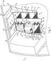
- connection assembly 1 of an electronic equipment 2comprises at least one support means 4 and a connection interface 6.
- the connection assembly 1is arranged in an aircraft, and connects the electronic equipment 2 to the wiring 3 of the aircraft.
- the support means 4forms a kind of furniture that includes modules 8 of substantially rectangular section.
- Each piece of furniture 4comprises, for example, a lower shelf 10, an intermediate shelf 11 and an upper shelf 12, connected by two lateral walls 14, which thus delimit a front face 16 and a rear face 18.
- the front face and the rear face of each moduleare open, without walls for easy access and handling.
- modules 8are here stacked on each other, to form a support means 4 of determined height.
- two support means 4are arranged side by side.
- the six modules 8have the same dimensions and are aligned, so that each rear face 18 is included in the same vertical plane.
- each support means 4may comprise a number of modules different from three and more than two means may be arranged adjacently.
- Sliding means 20are arranged on the faces facing the lower shelf 10 of the intermediate shelf 11 and of the upper shelf 12 of the same module 8.
- Each module 8is adapted to receive at least one electronic equipment 2 and a wiring box 30.
- the electronic equipment 2 and the wiring box 30 of each module 8are arranged for example vertically on each of the lower shelves 10, intermediate 11 and upper 12 of said furniture 4.
- the electronic equipment 2comprises a cover 22 for protection.
- the covercomprises ribs 24 forming complementary guide means adapted to cooperate with the slide means 20 arranged on the faces facing the shelves of the support means 4. Said ribs 24 extend axially on an upper face and a lower face of the hood 22.
- the electronic equipment 2further comprises, on a face of its cover 22 perpendicular to its upper and lower faces and perpendicular to the axial direction of extension of the ribs, first connection means.
- first connection meansWhen each electronic equipment 2 is inserted into a module 8 of the support means 4, said first connection means of each electronic equipment opens onto the rear face 18 of said module 8.
- the wiring box 30comprises a protective cover which has dimensions equivalent to the dimensions of the cover 22 of the electronic equipment 2.
- the wiring box 30comprises complementary guide means (not visible in the figures) adapted to cooperate with the sliding means 20 arranged on the faces facing the shelves of the support means 4. Two opposite faces, said front and rear of this wiring box comprise means for connecting the wiring 32, so that when the housing of wiring 30 is inserted into a module 8 of the support means 4, said wiring connection means open on the front face 16 and on the rear face 18 of said module 8.
- the opposite front and rear faces of the wiring box 30are arranged perpendicularly to the insertion direction of the housing in the module and perpendicular to the faces of the housing which comprise the complementary guide means.
- At least one connection interface 6is provided for connecting the wiring of the aircraft to the first connection means of the electronic equipment 2 carried by the modules 8 of the support means 4.
- connection interface moduleit is for example possible to have a connection interface module.
- an interfacecould be common to several modules.
- connection interfaceis for example made in the form of a substantially flat electronic card mounted at the rear face 18 of the furniture ( Figure 2 ), in an embodiment useful for understanding the invention but which is not part of it.
- the interfacehas for example an L-shape which is adapted to the arrangement of the wiring box 30 and the electronic equipment 2 in each module. Since there is a greater number of connection / wiring points between the wiring box 30 and the interface than between the electronic equipment and the interface, the interface extends substantially the entire dimension of the interface. rear panel of the wiring box but not along the entire back of the electronic equipment 2.
- the interfacehas an L shape whose vertical leg is facing the rear face of the wiring box 30, while the horizontal leg is facing only a portion of the rear face of the electronic equipment 2.
- DOther forms of interface can be envisaged depending on the arrangement of the elements in the modules 8, as a function of the connection requirements and the elements (nature, shape, number, etc.).
- connection interface 6is positioned substantially in line with the rear face 18 of the modules 8 (it is integral with each module 8), and has second connection means (not shown on the Figure 2 as they are oriented towards the interior of each module) which are partly adapted to be connected to the first connection means carried by the electronic equipment 2.
- a second part of these second connecting meansis also adapted to be connected to the wiring connection means 32 (connectors) of the wiring box 30 which are arranged on the rear face of the latter. This corresponds to an embodiment useful for understanding the invention but which is not part of it.
- connection interface 6is fixed to the structure 28 of the aircraft.
- the support means 4comprises two vertical lateral edges 41 formed by the respective lateral walls of the superposed modules 8, and a horizontal upper edge 42 formed by the upper shelf of the module disposed at the top of the support means 4.
- a passage or cable guide 31is formed of a box in which cables or bundles of cables 3 of the aircraft are arranged.
- the cable passage 31extends vertically along a vertical lateral edge 41 of the support means 4.
- said cable passage 31extends horizontally along the horizontal upper edge 42 of the support means .
- the horizontal boxis attached to a vertical wall of the aircraft from which the wiring comes out, or is connected to another vertical box which is provided with an internal opening at the connection so as to form a global box in the shape of an inverted L.
- the cable passage 31extends in the vicinity of the front face 16 of the support means 4, said cable passage 31 being connected to the wiring box 30 near this front face 16 of the support means 4 .
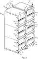
- a vertical upright 23is fixed against the structure 28 of the aircraft and guide rails 17a, 17b, 17c, 17d (two pairs, one pair for each piece of furniture) are fixed to the floor 25 of the aircraft, perpendicular to the amount 23 ( Figure 3 ).
- connection interface 6is installed in each module 8 of a first support means 4 (first furniture) at the rear face 18 and the stiffeners 19 are mounted between the side walls of the modules.
- the three modules 8are mounted one above the other.
- the first support means 4is brought against the upright 23 of the structure 28 of the aircraft, close to an opening 27 formed in the floor 25 to allow the passage of cables from the wiring of the aircraft and is, for example, secured to the structure 28.
- the electronic equipment 2 and the wiring box 30are already in place in the support means 4.
- the support meansis brought against the structure 28, and the electronic equipment and the wiring boxes are inserted after into the support means.
- the first support means 4may comprise means capable of facilitating its movement, not shown, such as wheels, or gripping means for a handling device.
- guide meansdisposed in the vicinity of the structure 28.
- these guide meansare here vertical walls 43, 44, integral with the structure 28 of the aircraft and which s' extending perpendicularly to the interior of the aircraft from this structure. These walls frame the amount 23.
- the first support means 4is arranged in a first direction between the lateral structure 28 of the aircraft and the passage of cables 31 and in a second direction perpendicular between said passage of cables 31 and a first wall 43 of the structure 28.
- a second support means 4(second piece of furniture) is similarly brought against the upright 23 of the structure 28.
- the second support meansis arranged in a first direction between the lateral structure 28 and the passage of cables 31, and in a second perpendicular direction, between said passage of cables 31 and a second wall 44 of the structure 28.
- the two support means 4are here positioned side by side so that the cable passage 31 extends in the vicinity of the front face of each support means and for example, more precisely, in the vicinity of a vertical lateral edge 41. .
- the casing 31, also called sheath,is placed above the opening 27 and the wire bundles 3 through are installed inside the box and are positioned appropriately at the different holes 29 provided in the box to come out of said box through them for their connection.
- the holesare made for example over substantially the entire height of the box (or alternatively according to a portion of the height) in order to distribute the bundles of cables at different heights for different modules 8.
- the holes 29are for example made on two opposite sides of the box with only one face visible on the figures 1 and 3 .
- holescould be made on each side to facilitate the installation of the box on the floor.
- the cable harnesses 3 of the cable passage 31are then connected to a first end (front face) of at least one wiring box 30, by means of the wiring connection means 32 (connectors) carried by this first end. and which open on the front face 16 of module 8 ( Figure 1 ).
- connection interface 6The other end (rear face) of this wiring box 30 being connected to the connection interface 6, thus makes a connection of the electronic equipment 2 to the wiring 3 of the aircraft via, successively, a connection interface 6 and a wiring box 30.
- a cable guideis common to two furniture and, alternatively, could be used with more than two furniture depending on the shape and dimensions of the cable guide and the layout of the cable guide in relation to the furniture.
- connection interface 6is arranged in the support means 4, so that the connection between the connection interface 6 and the wiring 3 of the aircraft is ensured through said support means 4.
Landscapes
- Engineering & Computer Science (AREA)
- Microelectronics & Electronic Packaging (AREA)
- Connection Or Junction Boxes (AREA)
Description
Translated fromFrenchLa présente invention concerne un ensemble de connexion d'au moins un équipement électronique dans un aéronef.The present invention relates to a connection assembly of at least one electronic equipment in an aircraft.
Dans un aéronef, de nombreux équipements électroniques sont localisés dans une zone située sous le cockpit de l'aéronef, qui offre aux équipements des conditions environnementales privilégiées telles qu'une pression ambiante raisonnable et une température ambiante maîtrisée. Des moyens de support sont disposés dans cette zone et permettent de fixer les équipements, de les connecter aux câbles de l'aéronef et de les ventiler.In an aircraft, many electronic equipment is located in an area under the cockpit of the aircraft, which provides the equipment with preferred environmental conditions such as a reasonable ambient pressure and a controlled ambient temperature. Support means are arranged in this area and allow to fix the equipment, connect to the cables of the aircraft and ventilate them.
Le document
Le document
Le document
L'invention vise à proposer un ensemble de connexion d'un équipement électronique simplifié par rapport à l'art antérieur, notamment dans les opérations d'installation, de câblage, et de manutention ultérieure de l'ensemble électronique.The aim of the invention is to propose a connection assembly of simplified electronic equipment with respect to the prior art, particularly in installation, wiring, and subsequent handling of the electronic assembly.
A cet effet, l'invention a pour objet un ensemble de connexion d'au moins un équipement électronique au câblage d'un aéronef, dans lequel ledit au moins un équipement électronique est disposé dans un moyen de support et comporte des moyens de connexion aptes à être raccordés au câblage de l'aéronef par l'intermédiaire d'au moins une interface de connexion ladite au moins une interface de connexion étant raccordée au câblage par l'intermédiaire d'un boîtier de câblage interposé entre ladite interface et le câblage, ledit boîtier de câblage étant disposé dans le moyen de support pour assurer la connexion entre l'interface de connexion et le câblage à travers ledit moyen de support, le moyen de support comportant une face avant et une face arrière au niveau de laquelle est disposée ladite au moins une interface de connexion, caractérisée en ce que l'ensemble de connexion repose sur une surface et comporte un caisson dans lequel est disposé le câblage et qui s'étend au voisinage de la face avant du moyen de support, le caisson étant disposé au-dessus d'une ouverture pratiquée dans ladite surface et le câblage traversant l'ouverture pour pénétrer dans le caisson, en ce que ladite au moins une interface de connexion est fixée à la structure de l'aéronef, et en ce que des moyens de guidage sont disposés sur la structure de l'aéronef pour guider le moyen de support en regard de l'interface de connexion.For this purpose, the invention relates to a connection assembly of at least one electronic equipment to the wiring of an aircraft, wherein said at least one electronic equipment is disposed in a support means and comprises suitable connection means to be connected to the wiring of the aircraft via at least one connection interface, said at least one connection interface being connected to the wiring via a wiring box interposed between said interface and the wiring, said wiring box being disposed in the support means for providing connection between the connection interface and the wiring through said support means, the support means having a front face and a rear face at which said support means is disposed at least one connection interface, characterized in that the connection assembly rests on a surface and comprises a box in which the wiring is arranged and i extends in the vicinity of the front face of the support means, the box being disposed above an opening in said surface and the wiring passing through the opening to enter the box, in that said at least one connection interface is fixed to the aircraft structure, and in that guide means are arranged on the aircraft structure to guide the support means facing the connection interface.
Un tel ensemble de connexion permet avantageusement de réduire l'encombrement du câblage de l'aéronef du fait de l'intégration d'une partie de ce câblage dans des modules incorporés dans le moyen de support. Il permet un aménagement simplifié des zones de l'aéronef dans lesquelles des équipements électroniques doivent être raccordés au câblage.Such connection set advantageously reduces the size of the wiring of the aircraft due to the integration of a portion of this wiring in modules incorporated in the support means. It allows a simplified layout of the areas of the aircraft in which electronic equipment must be connected to the wiring.
En outre, la présence d'un passage de câbles en face avant du moyen de support permet notamment de protéger les câbles lors d'éventuelles manipulations par un opérateur et d'éviter que ce dernier ne trébuche sur le câblage. En effet, les abords de cette face avant sont susceptibles d'être plus fréquentés lors des manipulations. Le fait de rassembler les câbles offre également un gain de place non négligeable, ce qui est utile en face avant du moyen de support. Enfin, le passage de câbles permet de dissimuler les câbles ce qui, d'un point de vue esthétique, est appréciable.In addition, the presence of a cable passage in front of the support means in particular to protect the cables during any manipulation by an operator and to prevent it from tripping over the wiring. Indeed, the surroundings of this front face are likely to be more frequent during handling. Assembling the cables offers also a significant space saving, which is useful in the front face of the support means. Finally, the passage of cables makes it possible to conceal the cables which, from an aesthetic point of view, is appreciable.
Cette disposition en face avant rend la connexion du câblage de l'aéronef plus simple à réaliser et à contrôler (grâce à une visualisation des connexions). Par ailleurs, d'éventuelles modifications à apporter à la connexion, voire au câblage lui-même, sont plus simples à effectuer. Selon différentes caractéristiques :
- Le moyen de support comporte au moins un module de section sensiblement rectangulaire, dont le fond est en regard de l'interface de connexion, et dont la face avant est ouverte, ledit au moins un équipement électronique et le boîtier de câblage étant adaptés pour être insérés dans ledit au moins un module.
- Ledit au moins un module est adapté pour recevoir au moins un équipement électronique et un unique boîtier de câblage.
- Le boîtier de câblage est raccordé par une extrémité au câblage de l'aéronef au voisinage de la face avant dudit au moins un module, l'extrémité opposée dudit boîtier de câblage étant connectée dans le fond dudit au moins un module à ladite au moins une interface de connexion.
- Le moyen de support comporte plusieurs modules disposés les uns au dessus des autres.
- Ladite au moins une interface de connexion est intégrée au moyen de support.
- Deux moyens de support sont disposés côte à côte, un unique passage de câbles s'étendant au voisinage des deux moyens de support.
- Le meuble présente un système de refroidissement intégré ; le système de refroidissement du meuble est autonome, ou interconnecté avec le réseau de refroidissement de l'aéronef.
- Ladite au moins une interface de connexion s'étend sensiblement verticalement le long de la structure de l'aéronef.
- Le passage de câbles comprend un caisson dans lequel est disposé le câblage.
- Le câblage est disposé à la verticale, le caisson s'étendant verticalement.
- Le caisson est pourvu de trous disposés de façon à ce que les câbles ou faisceaux de câbles constituant le câblage ressortent du caisson à travers les trous en vue de leur raccordement à un ou plusieurs boîtiers de câblage disposés sensiblement au voisinage des trous.
- Le caisson est disposé au-dessus d'une ouverture pratiquée dans une surface (par exemple le plancher) sur laquelle repose l'ensemble de connexion. Le câblage de l'aéronef traverse ainsi l'ouverture pour pénétrer dans le caisson.
- Des moyens de guidage sont disposés sur la structure de l'aéronef, pour guider le moyen de support en regard de l'interface de connexion.
- The support means comprises at least one module of substantially rectangular section, whose bottom is opposite the connection interface, and whose front face is open, said at least one electronic equipment and the wiring box being adapted to be inserted into said at least one module.
- The at least one module is adapted to receive at least one electronic equipment and a single wiring box.
- The wiring box is connected at one end to the wiring of the aircraft in the vicinity of the front face of said at least one module, the opposite end of said wiring box being connected in the bottom of said at least one module to said at least one connection interface.
- The support means comprises a plurality of modules arranged one above the other.
- Said at least one connection interface is integrated in the support means.
- Two support means are arranged side by side, a single cable passage extending in the vicinity of the two support means.
- The cabinet has an integrated cooling system; the furniture cooling system is autonomous, or interconnected with the cooling network of the aircraft.
- Said at least one connection interface extends substantially vertically along the structure of the aircraft.
- The passage of cables comprises a box in which the wiring is arranged.
- The wiring is arranged vertically, the box extending vertically.
- The box is provided with holes arranged so that the cables or wiring harnesses constituting the wiring out of the box through the holes for their connection to one or more wiring boxes disposed substantially in the vicinity of the holes.
- The box is disposed above an opening in a surface (eg the floor) on which the connection assembly rests. The wiring of the aircraft thus passes through the opening to enter the box.
- Guiding means are arranged on the structure of the aircraft, to guide the support means facing the connection interface.
L'invention porte également sur un aéronef comportant au moins un ensemble de connexion d'un équipement électronique selon l'invention.The invention also relates to an aircraft comprising at least one connection assembly of electronic equipment according to the invention.
Les caractéristiques et avantages de l'invention ressortiront de la description qui suit, donnée à titre d'exemple préféré, mais non limitatif, en référence aux dessins annexés, sur lesquels :
- la
figure 1 est une représentation d'un ensemble de connexion selon l'invention; - la
figure 2 est une représentation schématique du moyen de support, vue de trois quart arrière, dans un mode de réalisation utile à la compréhension de l'invention mais qui n'en fait pas partie ; - la
figure 3 est une représentation de l'ensemble de connexion de lafigure 1 , dans une position alternative dans laquelle le moyen de support est en retrait par rapport à la structure de l'aéronef;
- the
figure 1 is a representation of a connection assembly according to the invention; - the
figure 2 is a schematic representation of the support means, seen from three quarter back, in an embodiment useful for understanding the invention but which is not part of it; - the
figure 3 is a representation of the connection set of thefigure 1 in an alternative position in which the support means is recessed relative to the aircraft structure;
L'ensemble de connexion 1 d'un équipement électronique 2 comporte au moins un moyen de support 4 et une interface de connexion 6. L'ensemble de connexion 1 est disposé dans un aéronef, et assure le raccordement de l'équipement électronique 2 au câblage 3 de l'aéronef.The connection assembly 1 of an
Le moyen de support 4 forme en quelque sorte un meuble qui comporte des modules 8 de section sensiblement rectangulaire. Chaque meuble 4 comporte par exemple une étagère inférieure 10, une étagère intermédiaire 11 et une étagère supérieure 12, reliées par deux parois latérales 14, qui délimitent ainsi une face avant 16 et une face arrière 18. La face avant et la face arrière de chaque module sont ouvertes, sans parois pour faciliter l'accès et les manipulations.The support means 4 forms a kind of furniture that includes
Tel qu'illustré, trois modules 8 sont ici empilés les uns sur les autres, pour former un moyen de support 4 de hauteur déterminée. En outre, ici, deux moyens de support 4 sont disposés côte à côte. Les six modules 8 ont les mêmes dimensions et sont alignés, de sorte que chaque face arrière 18 est comprise dans un même plan vertical.As illustrated, three
On notera que chaque moyen de support 4 peut comprendre un nombre de modules différent de trois et plus de deux moyens peuvent être disposés de façon adjacente.Note that each support means 4 may comprise a number of modules different from three and more than two means may be arranged adjacently.
Des moyens formant glissière 20 sont aménagés sur les faces en vis-à-vis de l'étagère inférieure 10 de l'étagère intermédiaire 11 et de l'étagère supérieure 12 d'un même module 8.Sliding means 20 are arranged on the faces facing the
Chaque module 8 est adapté pour recevoir au moins un équipement électronique 2 et un boîtier de câblage 30. L'équipement électronique 2 et le boîtier de câblage 30 de chaque module 8 sont disposés par exemple verticalement sur chacune des étagères inférieure 10, intermédiaire 11 et supérieure 12 dudit meuble 4.Each
L'équipement électronique 2 comporte un capot 22 de protection. Le capot comporte des nervures 24 formant des moyens de guidage complémentaires adaptés pour coopérer avec les moyens formant glissières 20 aménagés sur les faces en vis-à-vis des étagères du moyen de support 4. Lesdites nervures 24 s'étendent axialement sur une face supérieure et une face inférieure du capot 22.The
L'équipement électronique 2 comporte en outre, sur une face de son capot 22 perpendiculaire à ses faces supérieure et inférieure et perpendiculaire à la direction axiale d'extension des nervures, des premiers moyens de connexion. Lorsque chaque équipement électronique 2 est inséré dans un module 8 du moyen de support 4, lesdits premiers moyens de connexion de chaque équipement électronique débouchent sur la face arrière 18 dudit module 8.The
Le boîtier de câblage 30 comporte un capot de protection qui présente des dimensions équivalentes aux dimensions du capot 22 de l'équipement électronique 2. Le boîtier de câblage 30 comporte des moyens de guidage complémentaires (non visibles sur les figures) adaptés à coopérer avec les moyens formant glissières 20 aménagés sur les faces en vis-à-vis des étagères du moyen de support 4. Deux faces opposées dites avant et arrière de ce boîtier de câblage comportent des moyens de raccordement du câblage 32, de sorte que lorsque le boîtier de câblage 30 est inséré dans un module 8 du moyen de support 4, lesdits moyens de raccordement de câblage débouchent sur la face avant 16 et sur la face arrière 18 dudit module 8.The
Les faces avant et arrière opposées du boîtier de câblage 30 sont agencées perpendiculairement à la direction d'insertion du boîtier dans le module et perpendiculairement aux faces du boîtier qui comportent les moyens de guidage complémentaires.The opposite front and rear faces of the
Au moins une interface de connexion 6 est prévue pour le raccordement du câblage de l'aéronef aux premiers moyens de connexion des équipements électroniques 2 portés par les modules 8 du moyen de support 4.At least one
Il est par exemple envisageable de disposer d'une interface de connexion par module. Alternativement, une interface pourrait être commune à plusieurs modules.It is for example possible to have a connection interface module. Alternatively, an interface could be common to several modules.
Une telle interface de connexion est par exemple réalisée sous la forme d'une carte électronique, sensiblement plane, montée au niveau de la face arrière 18 du meuble (
L'interface a par exemple une forme en L qui est adaptée à l'agencement du boîtier de câblage 30 et des équipements électroniques 2 dans chaque module. Dans la mesure où il y a un plus grand nombre de points de connexion/câblage entre le boîtier de câblage 30 et l'interface qu'entre les équipements électroniques et l'interface, cette dernière s'étend suivant sensiblement toute la dimension de la face arrière du boîtier de câblage mais pas suivant toute la face arrière des équipements électroniques 2.The interface has for example an L-shape which is adapted to the arrangement of the
C'est pourquoi l'interface n'arrive qu'à mi-hauteur de cette face arrière comme représenté sur la
Ainsi, l'interface a une forme en L dont la branche verticale est en regard de la face arrière du boîtier de câblage 30, tandis que la branche horizontale est en regard d'une partie seulement de la face arrière des équipements électroniques 2. D'autres formes d'interface sont envisageables selon l'agencement des éléments dans les modules 8, en fonction des nécessités de connexion et des éléments (nature, forme, nombre ...).Thus, the interface has an L shape whose vertical leg is facing the rear face of the
Chaque interface de connexion 6 est positionnée sensiblement au droit de la face arrière 18 des modules 8 (elle est solidaire de chaque module 8), et présente des deuxièmes moyens de connexion (non représentés sur la
Selon une variante non représentée, l'interface de connexion 6 est fixée à la structure 28 de l'aéronef.According to a variant not shown, the
Comme illustré, le moyen de support 4 comporte deux bords latéraux verticaux 41 formés par les parois latérales respectives des modules 8 superposés, et un bord supérieur horizontal 42 formé par l'étagère supérieure du module disposé au sommet du moyen de support 4.As illustrated, the support means 4 comprises two vertical lateral edges 41 formed by the respective lateral walls of the superposed
Un passage ou guide de câbles 31 est formé d'un caisson dans lequel sont disposés des câbles ou faisceaux de câbles 3 de l'aéronef. Ici, le passage de câbles 31 s'étend verticalement, le long d'un bord latéral vertical 41 du moyen de support 4. En variante, ledit passage de câbles 31 s'étend horizontalement le long du bord supérieur horizontal 42 du moyen de support. Selon d'autres variantes, le caisson horizontal est fixé à une paroi verticale de l'aéronef d'où sort le câblage, ou est raccordé à un autre caisson vertical qui est muni d'une ouverture interne au niveau du raccordement de sorte à former un caisson global en forme de L inversé. Dans tous les cas, le passage de câbles 31 s'étend au voisinage de la face avant 16 du moyen de support 4, ledit passage de câbles 31 étant raccordé au boîtier de câblage 30 à proximité de cette face avant 16 du moyen de support 4.A passage or
On va maintenant décrire la mise en place et l'utilisation d'un tel ensemble de connexion.We will now describe the establishment and use of such a connection set.
Préalablement, un montant vertical 23 est fixé contre la structure 28 de l'aéronef et des rails de guidage 17a, 17b, 17c, 17d, (soit deux paires, une paire pour chaque meuble) sont fixés au plancher 25 de l'aéronef, perpendiculairement au montant 23 (
Une interface de connexion 6 est installée dans chaque module 8 d'un premier moyen de support 4 (premier meuble) au niveau de la face arrière 18 et des raidisseurs 19 sont montés entre les parois latérales des modules. Les trois modules 8 sont montés les uns au-dessus des autres.A
Le premier moyen de support 4 est amené contre le montant 23 de la structure 28 de l'aéronef, à proximité d'une ouverture 27 pratiquée dans le plancher 25 pour permettre la traversée de câbles du câblage de l'aéronef et est, par exemple, rendu solidaire de la structure 28. Lors de cette mise en place du premier moyen de support, l'équipement électronique 2 et le boîtier de câblage 30 sont déjà en place dans le moyen de support 4. En variante, le moyen de support est amené contre la structure 28, et les équipements électroniques et les boîtiers de câblage sont insérés après dans le moyen de support.The first support means 4 is brought against the
On notera dans ces deux cas que l'établissement des connexions, d'une part, entre les équipements électroniques 2 et l'interface de connexion 6 et, d'autre part, entre le boîtier de câblage 30 et l'interface de connexion 6 peut être réalisée très simplement « en aveugle » : on insère chacune des unités 2 et 30 à l'intérieur d'un module jusqu'à venir en contact au fond avec l'interface, emboîtant ainsi les connecteurs mâles de l'un des éléments avec les connecteurs femelles de l'autre élément. On réalise ainsi simplement de cette façon l'établissement des connexions électriques.It will be noted in these two cases that the establishment of the connections, on the one hand, between the
On notera qu'un verrouillage mécanique des unités avec l'interface peut être également effectué.It will be noted that a mechanical locking of the units with the interface can also be performed.
Le premier moyen de support 4 peut comporter des moyens aptes à faciliter son déplacement, non représentés, comme des roulettes, ou des moyens de prise pour un appareil de manutention.The first support means 4 may comprise means capable of facilitating its movement, not shown, such as wheels, or gripping means for a handling device.
Le guidage en translation est facilité par la présence de moyens de guidage disposés au voisinage de la structure 28. Comme illustré, ces moyens de guidage sont ici des parois verticales 43, 44, solidaires de la structure 28 de l'aéronef et qui s'étendant perpendiculairement vers l'intérieur de l'aéronef à partir de cette structure. Ces parois encadrent le montant 23.The guidance in translation is facilitated by the presence of guide means disposed in the vicinity of the
Le premier moyen de support 4 est disposé selon une première direction entre la structure latérale 28 de l'aéronef et le passage de câbles 31 et selon une deuxième direction perpendiculaire entre ledit passage de câbles 31 et une première paroi 43 de la structure 28.The first support means 4 is arranged in a first direction between the
Un deuxième moyen de support 4 (deuxième meuble) est amené de façon similaire contre le montant 23 de la structure 28. Le deuxième moyen de support est disposé selon une première direction entre la structure latérale 28 et le passage de câbles 31, et selon une deuxième direction perpendiculaire, entre ledit passage de câbles 31 et une deuxième paroi 44 de la structure 28.A second support means 4 (second piece of furniture) is similarly brought against the
Les deux moyens de support 4 sont ici positionnés côte à côte de sorte que le passage de câbles 31 s'étend au voisinage de la face avant de chaque moyen de support et par exemple, plus précisément, au voisinage d'un bord latéral vertical 41.The two support means 4 are here positioned side by side so that the
Le caisson 31, également appelé fourreau, est mis en place au dessus de l'ouverture 27 et les faisceaux de câbles 3 traversants sont installés à l'intérieur du caisson et sont positionnés de façon appropriée au niveau des différents trous 29 prévus dans le caisson pour ressortir dudit caisson à travers ceux-ci en vue de leur raccordement.The
Les trous sont pratiqués par exemple sur sensiblement toute la hauteur du caisson (ou alternativement selon une partie de la hauteur) afin de distribuer les faisceaux de câbles à différentes hauteurs pour différents modules 8. Les trous 29 sont par exemple réalisés sur deux faces opposées du caisson dont seule une face est visible sur les
Alternativement, des trous pourraient être pratiqués sur chaque face pour faciliter l'installation du caisson sur le plancher.Alternatively, holes could be made on each side to facilitate the installation of the box on the floor.
Dès lors les faisceaux de câbles munis de leurs connecteurs débouchent en dehors des trous du caisson et pendent le long de celui-ci, prêts pour le raccordement.Then the bundles of cables with their connectors open out of the holes of the box and hang along it, ready for connection.
On raccorde alors les faisceaux de câbles 3 du passage de câbles 31 à une première extrémité (face avant) d'au moins un boîtier de câblage 30, par l'intermédiaire des moyens de raccordement au câblage 32 (connecteurs) portés par cette première extrémité et qui débouchent sur la face avant 16 du module 8 (
L'autre extrémité (face arrière) de ce boîtier de câblage 30 étant connectée à l'interface de connexion 6, on réalise ainsi une connexion des équipements électroniques 2 au câblage 3 de l'aéronef par l'intermédiaire, successivement, d'une interface de connexion 6 et d'un boîtier de câblage 30.The other end (rear face) of this
Par ailleurs, dans l'exemple un guide de câbles est commun à deux meubles et, alternativement, pourrait être utilisé avec plus de deux meubles selon la forme, et les dimensions du guide de câbles et selon la disposition de ce dernier par rapport aux meubles.By the way, in the example a cable guide is common to two furniture and, alternatively, could be used with more than two furniture depending on the shape and dimensions of the cable guide and the layout of the cable guide in relation to the furniture.
On notera que les boîtiers de câblage 30 sont disposés dans le moyen de support 4, de sorte que la connexion entre l'interface de connexion 6 et le câblage 3 de l'aéronef est assurée à travers ledit moyen de support 4.It will be noted that the
Claims (10)
- Connection assembly (1) for at least one item of electronic equipment (2) to the wiring (3) of an aircraft, in which the said at least one item of electronic equipment (2) is disposed in a support means (4) and comprises connection means able to be connected to the wiring (3) of the aircraft through at least one connection interface (6), the said at least one connection interface (6) being connected to the wiring (3) through a wiring box (30) interposed between the said interface (6) and the wiring (3), the said wiring box (30) being disposed in the support means (4) to provide the connection between the connection interface (6) and the wiring (3) through the said support means (4), the support means (4) comprising a front face (16) and a rear face (18) on which there is disposed at least one connection interface (6),characterized in that the connection assembly (1) rests on a surface and comprises a box (31) in which the wiring (3) is disposed and which extends to the vicinity of the front face (16) of the support means, the box (31) being disposed above an opening (27) made in said surface and the wiring (3) passing through said opening in order to enter the box (31),in that said at least one connection interface (6) is attached to the structure of the aircraft, andin that guide means (17, 43, 44) are disposed on the structure of the aircraft in order to guide the support means (4) opposite the connection interface (6).
- Connection assembly according to claim 1,characterized in that the support means (4) comprises at least one module (8) with more or less rectangular section, the back of which is opposite the connection interface (6), and the front face (16) of which is open, the said at least one item of electronic equipment (2) and the wiring box (30) being adapted for being inserted into the said at least one module (8).
- Connection assembly according to claim 2,characterized in that the said at least one module (8) is adapted for accommodating at least one item of electronic equipment (2) and a sole wiring box (30).
- Connection assembly according to claim 2 or 3,characterized in that the wiring box (30) is connected by one end to the wiring (3) of the aircraft in the vicinity of the front face (16) of the said at least one module (8), the opposite end of the said wiring box (30) being connected in the back of the said at least one module (8) to the said at least one connection interface (6) .
- Connection assembly according to one of claims 2 to 4,characterized in that the support means (4) comprises several modules (8) disposed one on top of the other.
- Connection assembly according to one of the preceding claims,characterized in that the said at least one connection interface (6) is integrated into the support means (4).
- Connection assembly according to claim 1,characterized in that the wiring is disposed vertically, the box extending vertically.
- Connection assembly according to claim 1 or 7,characterized in that the box is provided with holes disposed so that the cables or cable bundles making up the wiring (3) emerge from the said box through the said holes with a view to their connection to at least one wiring box.
- Connection assembly according to one of claims 1 to 8,characterized in that two support means (4) are disposed side by side, a sole cable passage (31) extending to the vicinity of the two support means (4).
- Aircraftcharacterized in that it comprises at least one connection assembly for an item of electronic equipment according to one of claims 1 to 9.
Applications Claiming Priority (1)
| Application Number | Priority Date | Filing Date | Title |
|---|---|---|---|
| FR1050838AFR2956279B1 (en) | 2010-02-05 | 2010-02-05 | FRONT WIRING CONNECTION ASSEMBLY OF AT LEAST ONE ELECTRONIC EQUIPMENT IN AN AIRCRAFT |
Publications (2)
| Publication Number | Publication Date |
|---|---|
| EP2355637A1 EP2355637A1 (en) | 2011-08-10 |
| EP2355637B1true EP2355637B1 (en) | 2019-01-23 |
Family
ID=42133706
Family Applications (1)
| Application Number | Title | Priority Date | Filing Date |
|---|---|---|---|
| EP11153451.7AActiveEP2355637B1 (en) | 2010-02-05 | 2011-02-04 | Frontal cabling connection unit of at least one electronic device in an aircraft |
Country Status (3)
| Country | Link |
|---|---|
| US (1) | US20110194269A1 (en) |
| EP (1) | EP2355637B1 (en) |
| FR (1) | FR2956279B1 (en) |
Families Citing this family (10)
| Publication number | Priority date | Publication date | Assignee | Title |
|---|---|---|---|---|
| FR2956278A1 (en)* | 2010-02-05 | 2011-08-12 | Airbus Operations Sas | CONNECTION ASSEMBLY OF AT LEAST ONE ELECTRONIC EQUIPMENT IN AN AIRCRAFT |
| FR2974682B1 (en)* | 2011-04-26 | 2014-01-10 | Airbus Operations Sas | ELECTRIC DISTRIBUTION HEART AND VEHICLE COMPRISING SUCH A HEART |
| FR2980459B1 (en) | 2011-09-22 | 2014-06-27 | Airbus Operations Sas | MODULE OF ELECTRICAL DEVICES FOR AVIONIC BAY |
| CN103843475B (en)* | 2011-09-30 | 2016-10-26 | 空中客车运营简化股份公司 | The electric power maincenter of airborne vehicle |
| CN105109702A (en)* | 2015-08-13 | 2015-12-02 | 中国航空工业集团公司西安飞机设计研究所 | Side cabinet |
| FR3073119A1 (en)* | 2017-10-31 | 2019-05-03 | Airbus Operations | ASSEMBLY COMPRISING A CARRIER STRUCTURE COMPRISING VERTICAL STRUCTURAL ELEMENTS AND A MODULE COMPRISING ELECTRONIC EQUIPMENT FIXED ON THE FRONT PANEL OF THE VERTICAL STRUCTURAL ELEMENTS |
| US11760283B2 (en)* | 2019-04-05 | 2023-09-19 | 901D, Llc | Modular packaging for rugged electronics enclosures |
| US11943891B2 (en)* | 2020-05-08 | 2024-03-26 | Gulfstream Aerospace Corporation | Method and apparatus for electronics rack assembly and transportation |
| CN112706935B (en)* | 2020-12-29 | 2022-11-01 | 中国航空工业集团公司西安飞机设计研究所 | A maintenance-friendly limit equipment box |
| US12363846B1 (en)* | 2023-02-14 | 2025-07-15 | Amazon Technologies, Inc. | Cartridge for interconnectivity among rack-mounted computing components |
Family Cites Families (39)
| Publication number | Priority date | Publication date | Assignee | Title |
|---|---|---|---|---|
| US2938686A (en)* | 1957-02-04 | 1960-05-31 | Boeing Co | Aircraft electronic equipment assembly |
| US3541395A (en)* | 1968-11-15 | 1970-11-17 | Lockheed Aircraft Corp | Aviation rack with cooling ducts |
| US3676746A (en)* | 1970-12-23 | 1972-07-11 | Honeywell Inf Systems | Compatible modular circuit board connector |
| US4089040A (en)* | 1976-01-28 | 1978-05-09 | The Boeing Company | Electrical/electronic rack and plug-in modules therefor |
| US5216579A (en)* | 1992-01-29 | 1993-06-01 | International Business Machines Corporation | Rack based packaging system for computers with cable, cooling and power management module |
| US5348482A (en)* | 1993-06-11 | 1994-09-20 | The Whitaker Corporation | High density integrated backplane assembly |
| US5396405A (en)* | 1993-10-05 | 1995-03-07 | Thomas & Betts Corporation | Wiring cabinet having vertically aligned patch panels |
| US5854904A (en)* | 1996-10-15 | 1998-12-29 | Brown; Erik Lee | Object-oriented modular electronic component system |
| US6016252A (en)* | 1997-06-30 | 2000-01-18 | Emc Corporation | Cable management system |
| US6011221A (en)* | 1998-03-02 | 2000-01-04 | 3Com Corp. | Cable management apparatus and method |
| FR2783392B1 (en)* | 1998-09-15 | 2000-12-08 | Sextant Avionique | CONNECTION DEVICE FOR AN ASSEMBLY OF MODULAR ELECTRONIC CARD HOLDER STRUCTURES AND RACK EQUIPPED WITH SUCH A DEVICE, HOSTING SUCH AN ASSEMBLY |
| US6667891B2 (en)* | 2000-02-18 | 2003-12-23 | Rackable Systems, Inc. | Computer chassis for dual offset opposing main boards |
| US6571047B1 (en)* | 2000-04-18 | 2003-05-27 | Sprint Spectrum, L.P. | Inter-bay fiber management assembly |
| US6452789B1 (en)* | 2000-04-29 | 2002-09-17 | Hewlett-Packard Company | Packaging architecture for 32 processor server |
| US6541705B1 (en)* | 2000-07-28 | 2003-04-01 | Panduit Corp. | Cable management rack |
| US6489565B1 (en)* | 2000-09-15 | 2002-12-03 | Chatsworth Products, Inc. | Vertical cable management rack |
| FR2822130B1 (en)* | 2001-03-14 | 2003-06-27 | Labinal | AIRCRAFT WITH ELECTRIC WIRING |
| US6535382B2 (en)* | 2001-04-12 | 2003-03-18 | Johnson Controls Technology Company | Cooling system for electronic equipment cabinets |
| JP4041985B2 (en)* | 2001-10-30 | 2008-02-06 | エゲネラ,インク. | Simple structure power and data connector for use in chassis devices containing multiple processors |
| US6845206B2 (en)* | 2002-06-11 | 2005-01-18 | Alcoa Fujikura Limited | Interbay housing assembly for fiber optic management systems |
| US6975511B1 (en)* | 2002-07-18 | 2005-12-13 | Rockwell Collins | Ruggedized electronic module cooling system |
| US6797879B2 (en) | 2002-09-17 | 2004-09-28 | The Boeing Company | Avionics tray assembly and seal assembly |
| US6842334B2 (en)* | 2002-09-18 | 2005-01-11 | Verari Systems, Inc. | Portable diagnostic apparatus for computer components and systems and method of using same |
| US7289334B2 (en)* | 2003-08-27 | 2007-10-30 | Epicenter, Inc. | Rack architecture and management system |
| US7408772B2 (en)* | 2004-05-14 | 2008-08-05 | Hewlett-Packard Development Company, L.P. | Fan tray electronics enclosure |
| US7417188B2 (en)* | 2004-09-13 | 2008-08-26 | Leviton Manufacturing Co., Inc. | Cable management system |
| US7087840B2 (en)* | 2004-12-03 | 2006-08-08 | Hubbell Incorporated | Cable management system with patch panel |
| US7813143B2 (en)* | 2005-04-15 | 2010-10-12 | Adc Telecommunications, Inc. | Conversion module and chassis arrangement, and related methods |
| US7437048B2 (en)* | 2005-08-18 | 2008-10-14 | Tellabs Operations, Inc. | Equipment bay cable management system |
| US7724516B2 (en)* | 2005-08-26 | 2010-05-25 | The Boeing Company | Cooling enclosure for maintaining commercial-off-the-shelf (COTS) equipment in vehicles |
| FR2894085B1 (en)* | 2005-11-30 | 2011-04-29 | Labinal | ELECTRICAL CABINET HAVING WIRING SUPPORT. |
| US8061534B2 (en)* | 2006-09-08 | 2011-11-22 | Leviton Manufacturing Co., Inc. | Equipment rack panel system and method |
| US8328026B2 (en)* | 2007-02-22 | 2012-12-11 | Tellabs Operations, Inc. | Apparatus and method for configuring a dual rack-mountable chassis |
| US7751206B2 (en)* | 2007-04-04 | 2010-07-06 | Dell Products L.P. | Cable management system |
| US7573708B2 (en)* | 2007-06-28 | 2009-08-11 | Sun Microsystems, Inc. | Upstream dust filters by retrofitting parallel path PCB cooling |
| FR2927222B1 (en)* | 2008-02-05 | 2010-10-15 | Thales Sa | ARRANGEMENT OF AVIONIC RACK |
| US8215498B2 (en)* | 2008-04-30 | 2012-07-10 | Raytheon Company | Modular rack system |
| US8040693B2 (en)* | 2008-10-02 | 2011-10-18 | Panduit Corp. | Universal expandable patch panel bracket |
| US20100110628A1 (en)* | 2008-10-30 | 2010-05-06 | Mark Barrenechea | Apparatus and Method for Enhancing the Maintainability and Cooling of Computer Components on Trays in a Cabinet |
- 2010
- 2010-02-05FRFR1050838Apatent/FR2956279B1/ennot_activeExpired - Fee Related
- 2011
- 2011-02-04USUS13/021,511patent/US20110194269A1/ennot_activeAbandoned
- 2011-02-04EPEP11153451.7Apatent/EP2355637B1/enactiveActive
Non-Patent Citations (1)
| Title |
|---|
| None* |
Also Published As
| Publication number | Publication date |
|---|---|
| FR2956279A1 (en) | 2011-08-12 |
| FR2956279B1 (en) | 2013-01-04 |
| EP2355637A1 (en) | 2011-08-10 |
| US20110194269A1 (en) | 2011-08-11 |
Similar Documents
| Publication | Publication Date | Title |
|---|---|---|
| EP2355637B1 (en) | Frontal cabling connection unit of at least one electronic device in an aircraft | |
| EP2779334B1 (en) | Electrical enclosure with improved mechanical arrangement | |
| FR2711454A1 (en) | Angle connection for a cabinet, and electrical cabinet including such connections. | |
| EP2355636B1 (en) | Device for connecting at least one electronic device in an aircraft | |
| FR2980459A1 (en) | MODULE OF ELECTRICAL DEVICES FOR AVIONIC BAY | |
| FR3032991B1 (en) | EVENEMENTIAL STRUCTURE OF PARALLELEPIPEDIC FORM | |
| FR2623029A1 (en) | DISTRIBUTION SLAB FOR BUILDING WIRING AND METHOD FOR WIRING SLIDING ASSEMBLY | |
| FR2958829A1 (en) | MODULAR ASSEMBLY FOR FIXING ELECTRONIC MODULES | |
| EP2605349A1 (en) | Support structure of an electric control or protection apparatus of a medium-voltage electric cubicle | |
| FR3069564B1 (en) | TRANSPORTABLE STATIONARY SHELTER FOR THE STORAGE OF ELECTRIC ENERGY STORAGE MODULES | |
| EP2364075B1 (en) | Computer module for transportable IT hosting centre | |
| EP0921617B1 (en) | Holder for apparatus to be fastened alongside a channel | |
| EP0593362B1 (en) | Profile device for cabling of electrical apparatuses in a wall, appropriate frame and channel for assembling such a device | |
| EP2456031B1 (en) | Electric facility including switchgear translatably mounted in an opening made in a wall | |
| EP2190275A1 (en) | Housing for an electronic module for controlling a machine | |
| EP0573367B1 (en) | Electrical distribution raceway | |
| EP3182537B1 (en) | Articulated cable duct | |
| EP2805524B1 (en) | Support device used for the wiring of a patch panel in a patch closet | |
| EP4109689B1 (en) | Electrical cabinet comprising an electrically insulating element | |
| FR3060882A1 (en) | COLUMN FOR SUPPORTING AT LEAST ONE ELECTRICAL EQUIPMENT | |
| FR2667633A1 (en) | Partition panel and dismantleable partition comprising at least one such panel | |
| FR3002250A1 (en) | Building, has receiving frame comprising upper cross-piece and lower cross-piece, where opening of upper cross-piece defined between arms has clearance that is wider than width of bottom of U-shaped section of lower cross-piece | |
| EP0884815A1 (en) | Cableduct for a sealing or floor | |
| EP1342879A2 (en) | Single-piece metallic cabinet with a vertical curtain and reinforced base and support with rollers | |
| FR2683435A1 (en) | Supporting arrangement for high units, as in a fitted kitchen |
Legal Events
| Date | Code | Title | Description |
|---|---|---|---|
| PUAI | Public reference made under article 153(3) epc to a published international application that has entered the european phase | Free format text:ORIGINAL CODE: 0009012 | |
| AK | Designated contracting states | Kind code of ref document:A1 Designated state(s):AL AT BE BG CH CY CZ DE DK EE ES FI FR GB GR HR HU IE IS IT LI LT LU LV MC MK MT NL NO PL PT RO RS SE SI SK SM TR | |
| AX | Request for extension of the european patent | Extension state:BA ME | |
| 17P | Request for examination filed | Effective date:20120125 | |
| 17Q | First examination report despatched | Effective date:20160718 | |
| GRAP | Despatch of communication of intention to grant a patent | Free format text:ORIGINAL CODE: EPIDOSNIGR1 | |
| STAA | Information on the status of an ep patent application or granted ep patent | Free format text:STATUS: GRANT OF PATENT IS INTENDED | |
| INTG | Intention to grant announced | Effective date:20181018 | |
| GRAS | Grant fee paid | Free format text:ORIGINAL CODE: EPIDOSNIGR3 | |
| GRAA | (expected) grant | Free format text:ORIGINAL CODE: 0009210 | |
| STAA | Information on the status of an ep patent application or granted ep patent | Free format text:STATUS: THE PATENT HAS BEEN GRANTED | |
| AK | Designated contracting states | Kind code of ref document:B1 Designated state(s):AL AT BE BG CH CY CZ DE DK EE ES FI FR GB GR HR HU IE IS IT LI LT LU LV MC MK MT NL NO PL PT RO RS SE SI SK SM TR | |
| REG | Reference to a national code | Ref country code:GB Ref legal event code:FG4D Free format text:NOT ENGLISH | |
| REG | Reference to a national code | Ref country code:CH Ref legal event code:EP | |
| REG | Reference to a national code | Ref country code:AT Ref legal event code:REF Ref document number:1092479 Country of ref document:AT Kind code of ref document:T Effective date:20190215 | |
| REG | Reference to a national code | Ref country code:IE Ref legal event code:FG4D Free format text:LANGUAGE OF EP DOCUMENT: FRENCH | |
| REG | Reference to a national code | Ref country code:DE Ref legal event code:R096 Ref document number:602011055846 Country of ref document:DE | |
| REG | Reference to a national code | Ref country code:NL Ref legal event code:MP Effective date:20190123 | |
| PG25 | Lapsed in a contracting state [announced via postgrant information from national office to epo] | Ref country code:NL Free format text:LAPSE BECAUSE OF FAILURE TO SUBMIT A TRANSLATION OF THE DESCRIPTION OR TO PAY THE FEE WITHIN THE PRESCRIBED TIME-LIMIT Effective date:20190123 | |
| PG25 | Lapsed in a contracting state [announced via postgrant information from national office to epo] | Ref country code:NO Free format text:LAPSE BECAUSE OF FAILURE TO SUBMIT A TRANSLATION OF THE DESCRIPTION OR TO PAY THE FEE WITHIN THE PRESCRIBED TIME-LIMIT Effective date:20190423 Ref country code:PL Free format text:LAPSE BECAUSE OF FAILURE TO SUBMIT A TRANSLATION OF THE DESCRIPTION OR TO PAY THE FEE WITHIN THE PRESCRIBED TIME-LIMIT Effective date:20190123 Ref country code:ES Free format text:LAPSE BECAUSE OF FAILURE TO SUBMIT A TRANSLATION OF THE DESCRIPTION OR TO PAY THE FEE WITHIN THE PRESCRIBED TIME-LIMIT Effective date:20190123 Ref country code:LT Free format text:LAPSE BECAUSE OF FAILURE TO SUBMIT A TRANSLATION OF THE DESCRIPTION OR TO PAY THE FEE WITHIN THE PRESCRIBED TIME-LIMIT Effective date:20190123 Ref country code:SE Free format text:LAPSE BECAUSE OF FAILURE TO SUBMIT A TRANSLATION OF THE DESCRIPTION OR TO PAY THE FEE WITHIN THE PRESCRIBED TIME-LIMIT Effective date:20190123 Ref country code:FI Free format text:LAPSE BECAUSE OF FAILURE TO SUBMIT A TRANSLATION OF THE DESCRIPTION OR TO PAY THE FEE WITHIN THE PRESCRIBED TIME-LIMIT Effective date:20190123 Ref country code:PT Free format text:LAPSE BECAUSE OF FAILURE TO SUBMIT A TRANSLATION OF THE DESCRIPTION OR TO PAY THE FEE WITHIN THE PRESCRIBED TIME-LIMIT Effective date:20190523 | |
| REG | Reference to a national code | Ref country code:AT Ref legal event code:MK05 Ref document number:1092479 Country of ref document:AT Kind code of ref document:T Effective date:20190123 | |
| PG25 | Lapsed in a contracting state [announced via postgrant information from national office to epo] | Ref country code:RS Free format text:LAPSE BECAUSE OF FAILURE TO SUBMIT A TRANSLATION OF THE DESCRIPTION OR TO PAY THE FEE WITHIN THE PRESCRIBED TIME-LIMIT Effective date:20190123 Ref country code:LV Free format text:LAPSE BECAUSE OF FAILURE TO SUBMIT A TRANSLATION OF THE DESCRIPTION OR TO PAY THE FEE WITHIN THE PRESCRIBED TIME-LIMIT Effective date:20190123 Ref country code:IS Free format text:LAPSE BECAUSE OF FAILURE TO SUBMIT A TRANSLATION OF THE DESCRIPTION OR TO PAY THE FEE WITHIN THE PRESCRIBED TIME-LIMIT Effective date:20190523 Ref country code:BG Free format text:LAPSE BECAUSE OF FAILURE TO SUBMIT A TRANSLATION OF THE DESCRIPTION OR TO PAY THE FEE WITHIN THE PRESCRIBED TIME-LIMIT Effective date:20190423 Ref country code:HR Free format text:LAPSE BECAUSE OF FAILURE TO SUBMIT A TRANSLATION OF THE DESCRIPTION OR TO PAY THE FEE WITHIN THE PRESCRIBED TIME-LIMIT Effective date:20190123 Ref country code:GR Free format text:LAPSE BECAUSE OF FAILURE TO SUBMIT A TRANSLATION OF THE DESCRIPTION OR TO PAY THE FEE WITHIN THE PRESCRIBED TIME-LIMIT Effective date:20190424 | |
| REG | Reference to a national code | Ref country code:CH Ref legal event code:PL | |
| REG | Reference to a national code | Ref country code:DE Ref legal event code:R097 Ref document number:602011055846 Country of ref document:DE | |
| PG25 | Lapsed in a contracting state [announced via postgrant information from national office to epo] | Ref country code:MC Free format text:LAPSE BECAUSE OF FAILURE TO SUBMIT A TRANSLATION OF THE DESCRIPTION OR TO PAY THE FEE WITHIN THE PRESCRIBED TIME-LIMIT Effective date:20190123 Ref country code:AL Free format text:LAPSE BECAUSE OF FAILURE TO SUBMIT A TRANSLATION OF THE DESCRIPTION OR TO PAY THE FEE WITHIN THE PRESCRIBED TIME-LIMIT Effective date:20190123 Ref country code:SK Free format text:LAPSE BECAUSE OF FAILURE TO SUBMIT A TRANSLATION OF THE DESCRIPTION OR TO PAY THE FEE WITHIN THE PRESCRIBED TIME-LIMIT Effective date:20190123 Ref country code:RO Free format text:LAPSE BECAUSE OF FAILURE TO SUBMIT A TRANSLATION OF THE DESCRIPTION OR TO PAY THE FEE WITHIN THE PRESCRIBED TIME-LIMIT Effective date:20190123 Ref country code:CZ Free format text:LAPSE BECAUSE OF FAILURE TO SUBMIT A TRANSLATION OF THE DESCRIPTION OR TO PAY THE FEE WITHIN THE PRESCRIBED TIME-LIMIT Effective date:20190123 Ref country code:DK Free format text:LAPSE BECAUSE OF FAILURE TO SUBMIT A TRANSLATION OF THE DESCRIPTION OR TO PAY THE FEE WITHIN THE PRESCRIBED TIME-LIMIT Effective date:20190123 Ref country code:IT Free format text:LAPSE BECAUSE OF FAILURE TO SUBMIT A TRANSLATION OF THE DESCRIPTION OR TO PAY THE FEE WITHIN THE PRESCRIBED TIME-LIMIT Effective date:20190123 Ref country code:LU Free format text:LAPSE BECAUSE OF NON-PAYMENT OF DUE FEES Effective date:20190204 Ref country code:EE Free format text:LAPSE BECAUSE OF FAILURE TO SUBMIT A TRANSLATION OF THE DESCRIPTION OR TO PAY THE FEE WITHIN THE PRESCRIBED TIME-LIMIT Effective date:20190123 | |
| REG | Reference to a national code | Ref country code:BE Ref legal event code:MM Effective date:20190228 | |
| REG | Reference to a national code | Ref country code:IE Ref legal event code:MM4A | |
| PG25 | Lapsed in a contracting state [announced via postgrant information from national office to epo] | Ref country code:SM Free format text:LAPSE BECAUSE OF FAILURE TO SUBMIT A TRANSLATION OF THE DESCRIPTION OR TO PAY THE FEE WITHIN THE PRESCRIBED TIME-LIMIT Effective date:20190123 | |
| PLBE | No opposition filed within time limit | Free format text:ORIGINAL CODE: 0009261 | |
| STAA | Information on the status of an ep patent application or granted ep patent | Free format text:STATUS: NO OPPOSITION FILED WITHIN TIME LIMIT | |
| PG25 | Lapsed in a contracting state [announced via postgrant information from national office to epo] | Ref country code:CH Free format text:LAPSE BECAUSE OF NON-PAYMENT OF DUE FEES Effective date:20190228 Ref country code:AT Free format text:LAPSE BECAUSE OF FAILURE TO SUBMIT A TRANSLATION OF THE DESCRIPTION OR TO PAY THE FEE WITHIN THE PRESCRIBED TIME-LIMIT Effective date:20190123 Ref country code:LI Free format text:LAPSE BECAUSE OF NON-PAYMENT OF DUE FEES Effective date:20190228 | |
| 26N | No opposition filed | Effective date:20191024 | |
| PG25 | Lapsed in a contracting state [announced via postgrant information from national office to epo] | Ref country code:IE Free format text:LAPSE BECAUSE OF NON-PAYMENT OF DUE FEES Effective date:20190204 | |
| PG25 | Lapsed in a contracting state [announced via postgrant information from national office to epo] | Ref country code:BE Free format text:LAPSE BECAUSE OF NON-PAYMENT OF DUE FEES Effective date:20190228 Ref country code:SI Free format text:LAPSE BECAUSE OF FAILURE TO SUBMIT A TRANSLATION OF THE DESCRIPTION OR TO PAY THE FEE WITHIN THE PRESCRIBED TIME-LIMIT Effective date:20190123 | |
| PG25 | Lapsed in a contracting state [announced via postgrant information from national office to epo] | Ref country code:TR Free format text:LAPSE BECAUSE OF FAILURE TO SUBMIT A TRANSLATION OF THE DESCRIPTION OR TO PAY THE FEE WITHIN THE PRESCRIBED TIME-LIMIT Effective date:20190123 | |
| PG25 | Lapsed in a contracting state [announced via postgrant information from national office to epo] | Ref country code:MT Free format text:LAPSE BECAUSE OF FAILURE TO SUBMIT A TRANSLATION OF THE DESCRIPTION OR TO PAY THE FEE WITHIN THE PRESCRIBED TIME-LIMIT Effective date:20190123 | |
| PG25 | Lapsed in a contracting state [announced via postgrant information from national office to epo] | Ref country code:CY Free format text:LAPSE BECAUSE OF FAILURE TO SUBMIT A TRANSLATION OF THE DESCRIPTION OR TO PAY THE FEE WITHIN THE PRESCRIBED TIME-LIMIT Effective date:20190123 | |
| PG25 | Lapsed in a contracting state [announced via postgrant information from national office to epo] | Ref country code:HU Free format text:LAPSE BECAUSE OF FAILURE TO SUBMIT A TRANSLATION OF THE DESCRIPTION OR TO PAY THE FEE WITHIN THE PRESCRIBED TIME-LIMIT; INVALID AB INITIO Effective date:20110204 | |
| PGFP | Annual fee paid to national office [announced via postgrant information from national office to epo] | Ref country code:DE Payment date:20220217 Year of fee payment:12 | |
| PG25 | Lapsed in a contracting state [announced via postgrant information from national office to epo] | Ref country code:MK Free format text:LAPSE BECAUSE OF FAILURE TO SUBMIT A TRANSLATION OF THE DESCRIPTION OR TO PAY THE FEE WITHIN THE PRESCRIBED TIME-LIMIT Effective date:20190123 | |
| REG | Reference to a national code | Ref country code:DE Ref legal event code:R119 Ref document number:602011055846 Country of ref document:DE | |
| PG25 | Lapsed in a contracting state [announced via postgrant information from national office to epo] | Ref country code:DE Free format text:LAPSE BECAUSE OF NON-PAYMENT OF DUE FEES Effective date:20230901 | |
| PGFP | Annual fee paid to national office [announced via postgrant information from national office to epo] | Ref country code:GB Payment date:20240219 Year of fee payment:14 | |
| PGFP | Annual fee paid to national office [announced via postgrant information from national office to epo] | Ref country code:FR Payment date:20240221 Year of fee payment:14 |