EP2353978B1 - Telescopic bicycle kickstand structure - Google Patents
Telescopic bicycle kickstand structureDownload PDFInfo
- Publication number
- EP2353978B1 EP2353978B1EP20110152363EP11152363AEP2353978B1EP 2353978 B1EP2353978 B1EP 2353978B1EP 20110152363EP20110152363EP 20110152363EP 11152363 AEP11152363 AEP 11152363AEP 2353978 B1EP2353978 B1EP 2353978B1
- Authority
- EP
- European Patent Office
- Prior art keywords
- leg
- tubular
- bicycle
- sleeve
- foot
- Prior art date
- Legal status (The legal status is an assumption and is not a legal conclusion. Google has not performed a legal analysis and makes no representation as to the accuracy of the status listed.)
- Active
Links
Images

Classifications
- B—PERFORMING OPERATIONS; TRANSPORTING
- B62—LAND VEHICLES FOR TRAVELLING OTHERWISE THAN ON RAILS
- B62H—CYCLE STANDS; SUPPORTS OR HOLDERS FOR PARKING OR STORING CYCLES; APPLIANCES PREVENTING OR INDICATING UNAUTHORIZED USE OR THEFT OF CYCLES; LOCKS INTEGRAL WITH CYCLES; DEVICES FOR LEARNING TO RIDE CYCLES
- B62H1/00—Supports or stands forming part of or attached to cycles
- B62H1/02—Articulated stands, e.g. in the shape of hinged arms
Definitions
- the present inventionrelates to a telescopic bicycle kickstand structure.
- telescopic bicycle kickstandswhich are constituted by a bracket for fixing to the lower part of a bicycle frame, such as a city bike, mountain bike and the like, which bracket is articulated to a telescopic leg with a foot for resting on the ground.
- the legis constituted by a first tubular element, which is hinged to the bracket, and a second tubular element, which has such resting foot; the second tubular element is partly inserted into the first tubular element and it can be extracted therefrom and inserted therein for elongating or shortening, at will, the telescopic leg.
- Such a telescopic bicycle standhas reversible means for locking the position of the second tubular element with respect to the first.
- Such locking meansare provided by a screw which is located so as to pass, at a certain point and in a substantially radial direction, through the wall of the first tubular element, so as to be pressed against the underlying second tubular element, thus retaining it in the selected position.
- Such telescopic bicycle kickstandsalthough they are widespread and appreciated, present some room for improvement.
- Telescopic bicycle kickstandsare in and of themselves already quite complex compared to normal, non-extendable bicycle kickstands, and they require the use of a screw to lock the selected extended configuration; this screw presents a relatively hazardous element for a user, since if it is badly positioned and protrudes excessively, it can cause injury to the user who uses the bicycle kickstand improperly, or it can become entangled with a shoelace or the hem of a trouser leg or other garment.
- NL1032207discloses a telescopic bicycle kickstand having a combination of features as set forth in the pre-characterizing portion of the amended claim 1.
- the aim of the present inventionis to provide a telescopic bicycle kickstand structure that is better protected from impacts by the pedal crank and at the same time is safer than similar known bicycle kickstands.
- an object of the inventionis to provide a telescopic bicycle kickstand structure with levels of performance at least as high as those of known similar bicycle kickstands, which at the same time is simpler and cheaper than known similar bicycle kickstands.
- Another object of the inventionis to provide a telescopic bicycle kickstand structure, which can be extended or shortened with the same ease as known bicycle kickstands.
- Another object of the inventionis to provide a telescopic bicycle kickstand structure that can be produced using known systems and techniques.
- a telescopic bicycle kickstand structure according to the inventionis generally indicated by the reference numeral 10.
- the telescopic bicycle kickstand structure 10comprises a bracket 11 for fixing to the lower part of a bicycle frame, which bracket 11 is articulated to a telescopic leg 12 with a foot 13 for resting on the ground.
- the telescopic leg 12comprises a first element 14 which is coupled to the bracket 11, and a second element 15 which can be telescopically extended from the first element 14 and comprises the resting foot 13.
- the first element 14comprises a first part 16 which is hinged to the bracket 11, which first part 16 is constituted in turn by a hinged head 17 from which a clutch portion 18 extends which is shaped for pressing into a second, tubular part 19 of the first element 14.
- the sleeve 20has one end 21 which is shaped so as to complement an abutment portion 22 which is defined on the hinged head 17, and has corresponding contiguous tubular seats on its inside, a first seat 23 for the section 18a of the clutch portion 18 which remains outside the second part 19, and a second seat 24 for an end section 25 of the second part 19.
- the inner shoulder 26which is provided by the difference in section between the tubular seats 23 and 24, clearly visible in the sectional view in Figure 3 , defines an anti-unthreading abutment for the sleeve 20 in the direction of unthreading from the hinged head 17.
- the upper protection sleeve 20 of the leg 13is therefore retained on the leg 13 not by means of screws, but simply by interposition between two abutments that prevent it from performing a translational motion both in one direction and in the opposite direction, i.e. the abutment portion 22 in the hinged head 17 and the inner shoulder 26.
- This upper sleeve 20 for protecting the leg 13is made by molding of plastic material.
- the reversible means for locking the position of the second element 15 with respect to the first 14are provided by a screw 34 which is screwed, in a substantially radial direction, into a corresponding complementarily threaded hole 28 defined on a wall 27 of the tubular second part 19, so as to be screwed against a tubular element 29 of the second element 15 of the leg 13.
- the head of the screw 34is arranged so as to slide inside a protective slot 30 which is defined on a lower sleeve 31 associated with the foot 13.
- This protective slot 30accommodates the relative sliding of the head of the screw 34, which protrudes barely if at all from the wall of the lower sleeve 31 in which the slot 30 is defined; in this way the head of the screw 34 is never in a position that is hazardous to the user and it cannot represent an element in which a user's laces, or trouser legs, or other garment can become entangled.
- the tubular element 29 of the second element 15 of the leg 13is pressed, with an end 32 thereof, onto a corresponding clutch 33 which is defined inside the lower sleeve 31.
- the lower sleeve 31 and the foot 13form a single body, made of plastic material.
- a telescopic bicycle kickstand structurehas been provided which is quicker to assemble, although with the upper sleeve it comprises a novel and very useful component for protection against impacts by the pedal crank.
- the assembly sequenceis simple and quick and simply requires pressing of the second tubular part 19 of the first element 14 onto the clutch portion 18 of the first part 16, with the upper sleeve 20 interposed, then composing the second element 15 of the leg 13 by pressing the tubular element 29 onto the corresponding clutch 33 in the lower sleeve 31, and then coupling the first element 14 to the second element 15 to compose the leg 13, locking them with the screw 34.
- a telescopic bicycle kickstand structurewhich is free from protruding screws or other dangerous protrusions, and therefore safer and less hazardous even for a user who is not very careful.
- a bicycle kickstand structurehas been provided with levels of performance at least as high as those of known similar bicycle kickstands.
- a telescopic bicycle kickstand structurewhich can be extended or shortened with the same ease as known bicycle kickstands.
Landscapes
- Engineering & Computer Science (AREA)
- Mechanical Engineering (AREA)
- Footwear And Its Accessory, Manufacturing Method And Apparatuses (AREA)
- Mutual Connection Of Rods And Tubes (AREA)
- Vehicle Body Suspensions (AREA)
- Helmets And Other Head Coverings (AREA)
- Golf Clubs (AREA)
Description
- The present invention relates to a telescopic bicycle kickstand structure.
- Nowadays telescopic bicycle kickstands are known which are constituted by a bracket for fixing to the lower part of a bicycle frame, such as a city bike, mountain bike and the like, which bracket is articulated to a telescopic leg with a foot for resting on the ground.
- The leg is constituted by a first tubular element, which is hinged to the bracket, and a second tubular element, which has such resting foot; the second tubular element is partly inserted into the first tubular element and it can be extracted therefrom and inserted therein for elongating or shortening, at will, the telescopic leg.
- Such a telescopic bicycle stand has reversible means for locking the position of the second tubular element with respect to the first.
- Such locking means are provided by a screw which is located so as to pass, at a certain point and in a substantially radial direction, through the wall of the first tubular element, so as to be pressed against the underlying second tubular element, thus retaining it in the selected position.
- Such telescopic bicycle kickstands, although they are widespread and appreciated, present some room for improvement.
- Indeed, such bicycle kickstands do not offer any protection against impacts caused by the pedal crank which abuts against the leg when it is in the lowered configuration of use.
- Such impacts, even if they do not immediately endanger the leg, can immediately damage its aesthetic impact, especially with bicycle kickstands of a certain level of quality, and scratch it or break it after frequent impacts.
- Telescopic bicycle kickstands are in and of themselves already quite complex compared to normal, non-extendable bicycle kickstands, and they require the use of a screw to lock the selected extended configuration; this screw presents a relatively hazardous element for a user, since if it is badly positioned and protrudes excessively, it can cause injury to the user who uses the bicycle kickstand improperly, or it can become entangled with a shoelace or the hem of a trouser leg or other garment.
- The addition of a protective element to the leg of the bicycle kickstand, if such addition is implemented with one or more additional threaded elements, would make assembling the bicycle kickstand even more complex and burdensome, and the bicycle kickstand itself potentially more dangerous.
NL1032207 - The aim of the present invention is to provide a telescopic bicycle kickstand structure that is better protected from impacts by the pedal crank and at the same time is safer than similar known bicycle kickstands.
- Within this aim, an object of the invention is to provide a telescopic bicycle kickstand structure with levels of performance at least as high as those of known similar bicycle kickstands, which at the same time is simpler and cheaper than known similar bicycle kickstands.
- Another object of the invention is to provide a telescopic bicycle kickstand structure, which can be extended or shortened with the same ease as known bicycle kickstands.
- Another object of the invention is to provide a telescopic bicycle kickstand structure that can be produced using known systems and techniques.
- In accordance with the invention, there is provided a telescopic bicycle kickstand structure as defined in the appended claims.
- Further characteristics and advantages of the invention will become better apparent from the following detailed description of a preferred, but not exclusive, embodiment of the telescopic bicycle kickstand structure according to the invention, illustrated by way of non-limiting example in the accompanying drawings, wherein:
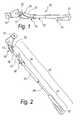
Figure 1 is a perspective view of a bicycle kickstand structure according to the invention;Figure 2 is an exploded view ofFigure 1 ;Figure 3 is a sectional side view of a first detail of the bicycle kickstand structure according to the invention;Figure 4 is another perspective view of the bicycle kickstand structure according to the invention;Figure 5 is a sectional side view of a second detail of the bicycle kickstand structure according to the invention.- A telescopic bicycle kickstand structure according to the invention is generally indicated by the
reference numeral 10. - The telescopic
bicycle kickstand structure 10 comprises abracket 11 for fixing to the lower part of a bicycle frame, whichbracket 11 is articulated to atelescopic leg 12 with afoot 13 for resting on the ground. - The
telescopic leg 12 comprises afirst element 14 which is coupled to thebracket 11, and asecond element 15 which can be telescopically extended from thefirst element 14 and comprises theresting foot 13. - There are reversible means for locking the position of the
second element 15 with respect to thefirst element 14. - The
first element 14 comprises afirst part 16 which is hinged to thebracket 11, whichfirst part 16 is constituted in turn by ahinged head 17 from which aclutch portion 18 extends which is shaped for pressing into a second,tubular part 19 of thefirst element 14. - Locked between the
first part 16 and thesecond part 19 of thefirst element 14, so as to surround the region of coupling between theclutch portion 18 and a first section of thesecond part 19, there is anupper sleeve 20, for protecting theleg 13, in the lowered configuration of use, from being struck by an improperly-rotated pedal crank of the bicycle. - The
sleeve 20 has oneend 21 which is shaped so as to complement anabutment portion 22 which is defined on thehinged head 17, and has corresponding contiguous tubular seats on its inside, afirst seat 23 for thesection 18a of theclutch portion 18 which remains outside thesecond part 19, and asecond seat 24 for anend section 25 of thesecond part 19. - The
inner shoulder 26 which is provided by the difference in section between thetubular seats Figure 3 , defines an anti-unthreading abutment for thesleeve 20 in the direction of unthreading from thehinged head 17. - The
upper protection sleeve 20 of theleg 13 is therefore retained on theleg 13 not by means of screws, but simply by interposition between two abutments that prevent it from performing a translational motion both in one direction and in the opposite direction, i.e. theabutment portion 22 in thehinged head 17 and theinner shoulder 26. - This
upper sleeve 20 for protecting theleg 13 is made by molding of plastic material. - The reversible means for locking the position of the
second element 15 with respect to the first 14 are provided by ascrew 34 which is screwed, in a substantially radial direction, into a corresponding complementarily threadedhole 28 defined on awall 27 of the tubularsecond part 19, so as to be screwed against atubular element 29 of thesecond element 15 of theleg 13. - In particular, advantageously, the head of the
screw 34 is arranged so as to slide inside aprotective slot 30 which is defined on alower sleeve 31 associated with thefoot 13. - This
protective slot 30 accommodates the relative sliding of the head of thescrew 34, which protrudes barely if at all from the wall of thelower sleeve 31 in which theslot 30 is defined; in this way the head of thescrew 34 is never in a position that is hazardous to the user and it cannot represent an element in which a user's laces, or trouser legs, or other garment can become entangled. - The
tubular element 29 of thesecond element 15 of theleg 13 is pressed, with anend 32 thereof, onto acorresponding clutch 33 which is defined inside thelower sleeve 31. - The
lower sleeve 31 and thefoot 13 form a single body, made of plastic material. - In practice it has been found that the invention fully achieves the intended aim and objects.
- In particular, with the invention a telescopic bicycle kickstand structure has been provided which is quicker to assemble, although with the upper sleeve it comprises a novel and very useful component for protection against impacts by the pedal crank.
- Indeed, the assembly sequence is simple and quick and simply requires pressing of the second
tubular part 19 of thefirst element 14 onto theclutch portion 18 of thefirst part 16, with theupper sleeve 20 interposed, then composing thesecond element 15 of theleg 13 by pressing thetubular element 29 onto thecorresponding clutch 33 in thelower sleeve 31, and then coupling thefirst element 14 to thesecond element 15 to compose theleg 13, locking them with thescrew 34. - In addition, with the invention a telescopic bicycle kickstand structure has been provided which is free from protruding screws or other dangerous protrusions, and therefore safer and less hazardous even for a user who is not very careful.
- Moreover, with the invention a bicycle kickstand structure has been provided with levels of performance at least as high as those of known similar bicycle kickstands.
- Also, with the invention a telescopic bicycle kickstand structure has been provided which can be extended or shortened with the same ease as known bicycle kickstands.
- Last but not least, with the invention a telescopic bicycle kickstand structure has been provided that can be produced using known systems and techniques.
- The invention thus conceived is susceptible of numerous modifications and variations, if these are within the scope of the appended claims.
- Where technical features mentioned in any claim are followed by reference signs, such reference signs have been inserted for the sole purpose of increasing the intelligibility of the claims and accordingly such reference signs do not have any limiting effect on the interpretation of each element identified by way of example by such reference signs.
Claims (5)
- A telescopic bicycle kickstand structure (10), of the type comprising a bracket (11) for fixing to the lower part of a bicycle frame, the bracket (11) being articulated to a telescopic leg (12) with a foot (13) for resting on the ground, said telescopic leg (12) comprising a first element (14) which is coupled to said bracket (11), and a second element (15) which can be telescopically extended from said first element (14) and comprises said foot (13), reversible means (34) being present for locking the position of the second element (15) with respect to the first (14), said first element (14) comprising a first part (16) which is hinged to the bracket (11); said first part (16) being constituted in turn by a hinged head (17) from which a clutch portion (18) extends which is shaped to be pressed into a second, tubular part (19) of said first element (14), an upper sleeve (20) being provided for protecting the leg (12), in the lowered configuration of use, from impacts by an improperly-rotated pedal crank of the bicycle, the bicycle kickstand structure beingcharacterized in that said upper sleeve (20) is locked between said first part (16) and said second part (19) of said first element (14), so as to surround the region of coupling between said clutch portion (18) and a first section of said second part (19), said sleeve (20) having one end (21) which is shaped so as to complement an abutment portion (22) which is defined on said hinged head (17), and on its inside having corresponding contiguous tubular seats (23, 24), a first seat (23) for the section (18a) of said clutch portion (18) which remains outside said second part (19), and a second seat (24) for an end section (25) of said second part (19), the inner shoulder (26) which is formed by the difference in section between said tubular seats (23, 24) defining an anti-unthreading abutment for said sleeve (20) in the direction of removal from the hinged head (17).
- The structure according to the claim 1,characterized in that said locking means are formed by a screw (34) which is screwed in a substantially radial direction into a corresponding complementarily threaded hole (28) defined on a wall (27) of said tubular second part (19), so as to be screwed against a tubular element (29) of the second element (15) of the leg (13), the head of said screw (34) being arranged so as to slide inside a protective slot (30) which is defined in a lower sleeve (31) which is associated with said foot (13).
- The structure according to the preceding claims,characterized in that said tubular element (29) of the second element (15) of the leg (13) is pressed, with an end (32) thereof, onto a corresponding clutch (33) which is defined inside said lower sleeve (31).
- The structure according to the preceding claims,characterized in that said lower sleeve (31) and said foot (13) form a single body, made of plastic material.
- The structure according to the preceding claims,characterized in that said upper sleeve (20) for protecting the foot (13) is made by molding of plastic material.
Applications Claiming Priority (1)
| Application Number | Priority Date | Filing Date | Title |
|---|---|---|---|
| ITPD20100002ITPD20100002U1 (en) | 2010-02-03 | 2010-02-03 | PERFECT STRUCTURE OF TELESCOPIC LOOP |
Publications (2)
| Publication Number | Publication Date |
|---|---|
| EP2353978A1 EP2353978A1 (en) | 2011-08-10 |
| EP2353978B1true EP2353978B1 (en) | 2013-10-23 |
Family
ID=43733741
Family Applications (1)
| Application Number | Title | Priority Date | Filing Date |
|---|---|---|---|
| EP20110152363ActiveEP2353978B1 (en) | 2010-02-03 | 2011-01-27 | Telescopic bicycle kickstand structure |
Country Status (2)
| Country | Link |
|---|---|
| EP (1) | EP2353978B1 (en) |
| IT (1) | ITPD20100002U1 (en) |
Cited By (30)
| Publication number | Priority date | Publication date | Assignee | Title |
|---|---|---|---|---|
| US8570725B2 (en) | 2012-03-02 | 2013-10-29 | Microsoft Corporation | Flexible hinge and removable attachment |
| US8654030B1 (en) | 2012-10-16 | 2014-02-18 | Microsoft Corporation | Antenna placement |
| US8719603B2 (en) | 2012-03-02 | 2014-05-06 | Microsoft Corporation | Accessory device authentication |
| US8733423B1 (en) | 2012-10-17 | 2014-05-27 | Microsoft Corporation | Metal alloy injection molding protrusions |
| US8749529B2 (en) | 2012-03-01 | 2014-06-10 | Microsoft Corporation | Sensor-in-pixel display system with near infrared filter |
| US8786767B2 (en) | 2012-11-02 | 2014-07-22 | Microsoft Corporation | Rapid synchronized lighting and shuttering |
| US8873227B2 (en) | 2012-03-02 | 2014-10-28 | Microsoft Corporation | Flexible hinge support layer |
| US8949477B2 (en) | 2012-05-14 | 2015-02-03 | Microsoft Technology Licensing, Llc | Accessory device architecture |
| US8947353B2 (en) | 2012-06-12 | 2015-02-03 | Microsoft Corporation | Photosensor array gesture detection |
| US8952892B2 (en) | 2012-11-01 | 2015-02-10 | Microsoft Corporation | Input location correction tables for input panels |
| US8964379B2 (en) | 2012-08-20 | 2015-02-24 | Microsoft Corporation | Switchable magnetic lock |
| US9019615B2 (en) | 2012-06-12 | 2015-04-28 | Microsoft Technology Licensing, Llc | Wide field-of-view virtual image projector |
| US9027631B2 (en) | 2012-10-17 | 2015-05-12 | Microsoft Technology Licensing, Llc | Metal alloy injection molding overflows |
| US9052414B2 (en) | 2012-02-07 | 2015-06-09 | Microsoft Technology Licensing, Llc | Virtual image device |
| US9064654B2 (en) | 2012-03-02 | 2015-06-23 | Microsoft Technology Licensing, Llc | Method of manufacturing an input device |
| US9073123B2 (en) | 2012-06-13 | 2015-07-07 | Microsoft Technology Licensing, Llc | Housing vents |
| US9075566B2 (en) | 2012-03-02 | 2015-07-07 | Microsoft Technoogy Licensing, LLC | Flexible hinge spine |
| US9152173B2 (en) | 2012-10-09 | 2015-10-06 | Microsoft Technology Licensing, Llc | Transparent display device |
| US9176538B2 (en) | 2013-02-05 | 2015-11-03 | Microsoft Technology Licensing, Llc | Input device configurations |
| US9256089B2 (en) | 2012-06-15 | 2016-02-09 | Microsoft Technology Licensing, Llc | Object-detecting backlight unit |
| US9317072B2 (en) | 2014-01-28 | 2016-04-19 | Microsoft Technology Licensing, Llc | Hinge mechanism with preset positions |
| US9355345B2 (en) | 2012-07-23 | 2016-05-31 | Microsoft Technology Licensing, Llc | Transparent tags with encoded data |
| US9354748B2 (en) | 2012-02-13 | 2016-05-31 | Microsoft Technology Licensing, Llc | Optical stylus interaction |
| US9360893B2 (en) | 2012-03-02 | 2016-06-07 | Microsoft Technology Licensing, Llc | Input device writing surface |
| US9426905B2 (en) | 2012-03-02 | 2016-08-23 | Microsoft Technology Licensing, Llc | Connection device for computing devices |
| US9448631B2 (en) | 2013-12-31 | 2016-09-20 | Microsoft Technology Licensing, Llc | Input device haptics and pressure sensing |
| US9447620B2 (en) | 2014-09-30 | 2016-09-20 | Microsoft Technology Licensing, Llc | Hinge mechanism with multiple preset positions |
| US9459160B2 (en) | 2012-06-13 | 2016-10-04 | Microsoft Technology Licensing, Llc | Input device sensor configuration |
| US9513748B2 (en) | 2012-12-13 | 2016-12-06 | Microsoft Technology Licensing, Llc | Combined display panel circuit |
| US9552777B2 (en) | 2013-05-10 | 2017-01-24 | Microsoft Technology Licensing, Llc | Phase control backlight |
Families Citing this family (22)
| Publication number | Priority date | Publication date | Assignee | Title |
|---|---|---|---|---|
| US9201185B2 (en) | 2011-02-04 | 2015-12-01 | Microsoft Technology Licensing, Llc | Directional backlighting for display panels |
| US9706089B2 (en) | 2012-03-02 | 2017-07-11 | Microsoft Technology Licensing, Llc | Shifted lens camera for mobile computing devices |
| US9870066B2 (en) | 2012-03-02 | 2018-01-16 | Microsoft Technology Licensing, Llc | Method of manufacturing an input device |
| USRE48963E1 (en) | 2012-03-02 | 2022-03-08 | Microsoft Technology Licensing, Llc | Connection device for computing devices |
| US10031556B2 (en) | 2012-06-08 | 2018-07-24 | Microsoft Technology Licensing, Llc | User experience adaptation |
| US9684382B2 (en) | 2012-06-13 | 2017-06-20 | Microsoft Technology Licensing, Llc | Input device configuration having capacitive and pressure sensors |
| WO2014059618A1 (en) | 2012-10-17 | 2014-04-24 | Microsoft Corporation | Graphic formation via material ablation |
| US10578499B2 (en) | 2013-02-17 | 2020-03-03 | Microsoft Technology Licensing, Llc | Piezo-actuated virtual buttons for touch surfaces |
| US9638835B2 (en) | 2013-03-05 | 2017-05-02 | Microsoft Technology Licensing, Llc | Asymmetric aberration correcting lens |
| US9304549B2 (en) | 2013-03-28 | 2016-04-05 | Microsoft Technology Licensing, Llc | Hinge mechanism for rotatable component attachment |
| US9759854B2 (en) | 2014-02-17 | 2017-09-12 | Microsoft Technology Licensing, Llc | Input device outer layer and backlighting |
| US10120420B2 (en) | 2014-03-21 | 2018-11-06 | Microsoft Technology Licensing, Llc | Lockable display and techniques enabling use of lockable displays |
| US10324733B2 (en) | 2014-07-30 | 2019-06-18 | Microsoft Technology Licensing, Llc | Shutdown notifications |
| US9424048B2 (en) | 2014-09-15 | 2016-08-23 | Microsoft Technology Licensing, Llc | Inductive peripheral retention device |
| US10416799B2 (en) | 2015-06-03 | 2019-09-17 | Microsoft Technology Licensing, Llc | Force sensing and inadvertent input control of an input device |
| US10222889B2 (en) | 2015-06-03 | 2019-03-05 | Microsoft Technology Licensing, Llc | Force inputs and cursor control |
| US9752361B2 (en) | 2015-06-18 | 2017-09-05 | Microsoft Technology Licensing, Llc | Multistage hinge |
| US9864415B2 (en) | 2015-06-30 | 2018-01-09 | Microsoft Technology Licensing, Llc | Multistage friction hinge |
| US10061385B2 (en) | 2016-01-22 | 2018-08-28 | Microsoft Technology Licensing, Llc | Haptic feedback for a touch input device |
| US10344797B2 (en) | 2016-04-05 | 2019-07-09 | Microsoft Technology Licensing, Llc | Hinge with multiple preset positions |
| US10037057B2 (en) | 2016-09-22 | 2018-07-31 | Microsoft Technology Licensing, Llc | Friction hinge |
| CN112323371B (en)* | 2020-11-28 | 2025-09-23 | 珠海格力电器股份有限公司 | Pipeline installation structure and clothing processing equipment including the same |
Family Cites Families (7)
| Publication number | Priority date | Publication date | Assignee | Title |
|---|---|---|---|---|
| GB699252A (en)* | 1950-12-27 | 1953-11-04 | J A Phillips And Company Ltd | Bicycle prop or strut |
| CN2693608Y (en)* | 2004-03-18 | 2005-04-20 | 财荣压铸股份有限公司 | Stilt structure for bicycle parking |
| TWM268259U (en)* | 2004-12-30 | 2005-06-21 | Moderne Tech Corp | Retractable positioning stand for bicycle |
| US7097191B2 (en)* | 2005-01-17 | 2006-08-29 | Griggs Terrance M | Adjustable kickstand with reinforced parking position lock |
| ITPD20050059U1 (en)* | 2005-07-22 | 2007-01-23 | Ursus Spa | PERFECT CYCLING |
| CN2818283Y (en)* | 2005-09-02 | 2006-09-20 | 优利工业股份有限公司 | Bicycle stand adjustment structure |
| NL1031037C2 (en)* | 2006-01-31 | 2007-08-01 | Spanninga Metaal | Bicycle stand. |
- 2010
- 2010-02-03ITITPD20100002patent/ITPD20100002U1/enunknown
- 2011
- 2011-01-27EPEP20110152363patent/EP2353978B1/enactiveActive
Cited By (69)
| Publication number | Priority date | Publication date | Assignee | Title |
|---|---|---|---|---|
| US9052414B2 (en) | 2012-02-07 | 2015-06-09 | Microsoft Technology Licensing, Llc | Virtual image device |
| US9354748B2 (en) | 2012-02-13 | 2016-05-31 | Microsoft Technology Licensing, Llc | Optical stylus interaction |
| US8749529B2 (en) | 2012-03-01 | 2014-06-10 | Microsoft Corporation | Sensor-in-pixel display system with near infrared filter |
| US9098117B2 (en) | 2012-03-02 | 2015-08-04 | Microsoft Technology Licensing, Llc | Classifying the intent of user input |
| US9116550B2 (en) | 2012-03-02 | 2015-08-25 | Microsoft Technology Licensing, Llc | Device kickstand |
| US8570725B2 (en) | 2012-03-02 | 2013-10-29 | Microsoft Corporation | Flexible hinge and removable attachment |
| US8719603B2 (en) | 2012-03-02 | 2014-05-06 | Microsoft Corporation | Accessory device authentication |
| US8724302B2 (en) | 2012-03-02 | 2014-05-13 | Microsoft Corporation | Flexible hinge support layer |
| US9465412B2 (en) | 2012-03-02 | 2016-10-11 | Microsoft Technology Licensing, Llc | Input device layers and nesting |
| US8646999B2 (en) | 2012-03-02 | 2014-02-11 | Microsoft Corporation | Pressure sensitive key normalization |
| US8780541B2 (en) | 2012-03-02 | 2014-07-15 | Microsoft Corporation | Flexible hinge and removable attachment |
| US8780540B2 (en) | 2012-03-02 | 2014-07-15 | Microsoft Corporation | Flexible hinge and removable attachment |
| US9460029B2 (en) | 2012-03-02 | 2016-10-04 | Microsoft Technology Licensing, Llc | Pressure sensitive keys |
| US8791382B2 (en) | 2012-03-02 | 2014-07-29 | Microsoft Corporation | Input device securing techniques |
| US8830668B2 (en) | 2012-03-02 | 2014-09-09 | Microsoft Corporation | Flexible hinge and removable attachment |
| US8850241B2 (en) | 2012-03-02 | 2014-09-30 | Microsoft Corporation | Multi-stage power adapter configured to provide low power upon initial connection of the power adapter to the host device and high power thereafter upon notification from the host device to the power adapter |
| US8854799B2 (en) | 2012-03-02 | 2014-10-07 | Microsoft Corporation | Flux fountain |
| US8873227B2 (en) | 2012-03-02 | 2014-10-28 | Microsoft Corporation | Flexible hinge support layer |
| US8896993B2 (en) | 2012-03-02 | 2014-11-25 | Microsoft Corporation | Input device layers and nesting |
| US8903517B2 (en) | 2012-03-02 | 2014-12-02 | Microsoft Corporation | Computer device and an apparatus having sensors configured for measuring spatial information indicative of a position of the computing devices |
| US8935774B2 (en) | 2012-03-02 | 2015-01-13 | Microsoft Corporation | Accessory device authentication |
| US8947864B2 (en) | 2012-03-02 | 2015-02-03 | Microsoft Corporation | Flexible hinge and removable attachment |
| US9426905B2 (en) | 2012-03-02 | 2016-08-23 | Microsoft Technology Licensing, Llc | Connection device for computing devices |
| US9411751B2 (en) | 2012-03-02 | 2016-08-09 | Microsoft Technology Licensing, Llc | Key formation |
| US9360893B2 (en) | 2012-03-02 | 2016-06-07 | Microsoft Technology Licensing, Llc | Input device writing surface |
| US8610015B2 (en) | 2012-03-02 | 2013-12-17 | Microsoft Corporation | Input device securing techniques |
| US9304948B2 (en) | 2012-03-02 | 2016-04-05 | Microsoft Technology Licensing, Llc | Sensing user input at display area edge |
| US9304949B2 (en) | 2012-03-02 | 2016-04-05 | Microsoft Technology Licensing, Llc | Sensing user input at display area edge |
| US9298236B2 (en) | 2012-03-02 | 2016-03-29 | Microsoft Technology Licensing, Llc | Multi-stage power adapter configured to provide a first power level upon initial connection of the power adapter to the host device and a second power level thereafter upon notification from the host device to the power adapter |
| US9047207B2 (en) | 2012-03-02 | 2015-06-02 | Microsoft Technology Licensing, Llc | Mobile device power state |
| US8614666B2 (en) | 2012-03-02 | 2013-12-24 | Microsoft Corporation | Sensing user input at display area edge |
| US9064654B2 (en) | 2012-03-02 | 2015-06-23 | Microsoft Technology Licensing, Llc | Method of manufacturing an input device |
| US9275809B2 (en) | 2012-03-02 | 2016-03-01 | Microsoft Technology Licensing, Llc | Device camera angle |
| US9075566B2 (en) | 2012-03-02 | 2015-07-07 | Microsoft Technoogy Licensing, LLC | Flexible hinge spine |
| US9268373B2 (en) | 2012-03-02 | 2016-02-23 | Microsoft Technology Licensing, Llc | Flexible hinge spine |
| US8699215B2 (en) | 2012-03-02 | 2014-04-15 | Microsoft Corporation | Flexible hinge spine |
| US9176900B2 (en) | 2012-03-02 | 2015-11-03 | Microsoft Technology Licensing, Llc | Flexible hinge and removable attachment |
| US9176901B2 (en) | 2012-03-02 | 2015-11-03 | Microsoft Technology Licensing, Llc | Flux fountain |
| US9134807B2 (en) | 2012-03-02 | 2015-09-15 | Microsoft Technology Licensing, Llc | Pressure sensitive key normalization |
| US9134808B2 (en) | 2012-03-02 | 2015-09-15 | Microsoft Technology Licensing, Llc | Device kickstand |
| US9146620B2 (en) | 2012-03-02 | 2015-09-29 | Microsoft Technology Licensing, Llc | Input device assembly |
| US9111703B2 (en) | 2012-03-02 | 2015-08-18 | Microsoft Technology Licensing, Llc | Sensor stack venting |
| US9158383B2 (en) | 2012-03-02 | 2015-10-13 | Microsoft Technology Licensing, Llc | Force concentrator |
| US9158384B2 (en) | 2012-03-02 | 2015-10-13 | Microsoft Technology Licensing, Llc | Flexible hinge protrusion attachment |
| US9348605B2 (en) | 2012-05-14 | 2016-05-24 | Microsoft Technology Licensing, Llc | System and method for accessory device architecture that passes human interface device (HID) data via intermediate processor |
| US8949477B2 (en) | 2012-05-14 | 2015-02-03 | Microsoft Technology Licensing, Llc | Accessory device architecture |
| US9098304B2 (en) | 2012-05-14 | 2015-08-04 | Microsoft Technology Licensing, Llc | Device enumeration support method for computing devices that does not natively support device enumeration |
| US8947353B2 (en) | 2012-06-12 | 2015-02-03 | Microsoft Corporation | Photosensor array gesture detection |
| US9019615B2 (en) | 2012-06-12 | 2015-04-28 | Microsoft Technology Licensing, Llc | Wide field-of-view virtual image projector |
| US9459160B2 (en) | 2012-06-13 | 2016-10-04 | Microsoft Technology Licensing, Llc | Input device sensor configuration |
| US9073123B2 (en) | 2012-06-13 | 2015-07-07 | Microsoft Technology Licensing, Llc | Housing vents |
| US9256089B2 (en) | 2012-06-15 | 2016-02-09 | Microsoft Technology Licensing, Llc | Object-detecting backlight unit |
| US9355345B2 (en) | 2012-07-23 | 2016-05-31 | Microsoft Technology Licensing, Llc | Transparent tags with encoded data |
| US8964379B2 (en) | 2012-08-20 | 2015-02-24 | Microsoft Corporation | Switchable magnetic lock |
| US9152173B2 (en) | 2012-10-09 | 2015-10-06 | Microsoft Technology Licensing, Llc | Transparent display device |
| US9432070B2 (en) | 2012-10-16 | 2016-08-30 | Microsoft Technology Licensing, Llc | Antenna placement |
| US8654030B1 (en) | 2012-10-16 | 2014-02-18 | Microsoft Corporation | Antenna placement |
| US8733423B1 (en) | 2012-10-17 | 2014-05-27 | Microsoft Corporation | Metal alloy injection molding protrusions |
| US8991473B2 (en) | 2012-10-17 | 2015-03-31 | Microsoft Technology Holding, LLC | Metal alloy injection molding protrusions |
| US9027631B2 (en) | 2012-10-17 | 2015-05-12 | Microsoft Technology Licensing, Llc | Metal alloy injection molding overflows |
| US8952892B2 (en) | 2012-11-01 | 2015-02-10 | Microsoft Corporation | Input location correction tables for input panels |
| US8786767B2 (en) | 2012-11-02 | 2014-07-22 | Microsoft Corporation | Rapid synchronized lighting and shuttering |
| US9544504B2 (en) | 2012-11-02 | 2017-01-10 | Microsoft Technology Licensing, Llc | Rapid synchronized lighting and shuttering |
| US9513748B2 (en) | 2012-12-13 | 2016-12-06 | Microsoft Technology Licensing, Llc | Combined display panel circuit |
| US9176538B2 (en) | 2013-02-05 | 2015-11-03 | Microsoft Technology Licensing, Llc | Input device configurations |
| US9552777B2 (en) | 2013-05-10 | 2017-01-24 | Microsoft Technology Licensing, Llc | Phase control backlight |
| US9448631B2 (en) | 2013-12-31 | 2016-09-20 | Microsoft Technology Licensing, Llc | Input device haptics and pressure sensing |
| US9317072B2 (en) | 2014-01-28 | 2016-04-19 | Microsoft Technology Licensing, Llc | Hinge mechanism with preset positions |
| US9447620B2 (en) | 2014-09-30 | 2016-09-20 | Microsoft Technology Licensing, Llc | Hinge mechanism with multiple preset positions |
Also Published As
| Publication number | Publication date |
|---|---|
| ITPD20100002U1 (en) | 2011-08-04 |
| EP2353978A1 (en) | 2011-08-10 |
Similar Documents
| Publication | Publication Date | Title |
|---|---|---|
| EP2353978B1 (en) | Telescopic bicycle kickstand structure | |
| US9957009B2 (en) | Support element for the human body | |
| US9102376B1 (en) | Bicycle quick release lock | |
| US5899481A (en) | Telescopic element, particularly for frames of folding bicycles | |
| US11358665B2 (en) | Support for two-wheeled vehicles | |
| JP4678533B2 (en) | hurdle | |
| CA2643539A1 (en) | Extendable scaffold bracket | |
| CN106805364B (en) | An adjustment structure for ice skates | |
| EP2602175A1 (en) | Kickstand with adjustable length | |
| US9366078B2 (en) | Protection device for blind string | |
| CN105946726A (en) | Vehicle side stepping bar | |
| EP3037330A1 (en) | Kickstand with adjustable length | |
| CN209825337U (en) | Lens quick assembly disassembly structure and helmet | |
| JP3191915U (en) | Bed guard | |
| WO2014191293A1 (en) | Shoetree with high versatility of use | |
| WO2006076395A3 (en) | Visor system | |
| ITPD20110025A1 (en) | ATTACHMENT FOR REVERSIBLE FASTENING OF SNOW EQUIPMENT, TYPES OF SNOWSHOES, SKINS, AND THE LIKE, WITH CORRESPONDING SHOES OR CORRESPONDING ACCESSORIES FOR FOOTWEAR, RAMPONI TYPE, ANTI-SLIP SHOES AND THE LIKE. | |
| WO2019088811A1 (en) | Body with doors for two-wheeled vehicle | |
| EP2384957A1 (en) | Kickstand on a bicycle frame | |
| IT201800002886A1 (en) | IMPROVED STRUCTURE OF CYCLE HOLDER | |
| KR20170050759A (en) | umbrella | |
| CN209645757U (en) | Sports equipment with folding function | |
| DK9200076U3 (en) | Bicycle pump with built-in bicycle lock | |
| US20120139208A1 (en) | Auxiliary Motorcycle Parking Stand | |
| KR200469967Y1 (en) | A prodective screen for Taxi driver |
Legal Events
| Date | Code | Title | Description |
|---|---|---|---|
| PUAI | Public reference made under article 153(3) epc to a published international application that has entered the european phase | Free format text:ORIGINAL CODE: 0009012 | |
| AK | Designated contracting states | Kind code of ref document:A1 Designated state(s):AL AT BE BG CH CY CZ DE DK EE ES FI FR GB GR HR HU IE IS IT LI LT LU LV MC MK MT NL NO PL PT RO RS SE SI SK SM TR | |
| AX | Request for extension of the european patent | Extension state:BA ME | |
| 17P | Request for examination filed | Effective date:20120209 | |
| GRAP | Despatch of communication of intention to grant a patent | Free format text:ORIGINAL CODE: EPIDOSNIGR1 | |
| INTG | Intention to grant announced | Effective date:20130514 | |
| GRAS | Grant fee paid | Free format text:ORIGINAL CODE: EPIDOSNIGR3 | |
| GRAA | (expected) grant | Free format text:ORIGINAL CODE: 0009210 | |
| AK | Designated contracting states | Kind code of ref document:B1 Designated state(s):AL AT BE BG CH CY CZ DE DK EE ES FI FR GB GR HR HU IE IS IT LI LT LU LV MC MK MT NL NO PL PT RO RS SE SI SK SM TR | |
| REG | Reference to a national code | Ref country code:GB Ref legal event code:FG4D | |
| REG | Reference to a national code | Ref country code:CH Ref legal event code:EP | |
| REG | Reference to a national code | Ref country code:AT Ref legal event code:REF Ref document number:637404 Country of ref document:AT Kind code of ref document:T Effective date:20131115 | |
| REG | Reference to a national code | Ref country code:IE Ref legal event code:FG4D | |
| REG | Reference to a national code | Ref country code:DE Ref legal event code:R096 Ref document number:602011003427 Country of ref document:DE Effective date:20131219 | |
| REG | Reference to a national code | Ref country code:NL Ref legal event code:T3 | |
| REG | Reference to a national code | Ref country code:AT Ref legal event code:MK05 Ref document number:637404 Country of ref document:AT Kind code of ref document:T Effective date:20131023 | |
| REG | Reference to a national code | Ref country code:LT Ref legal event code:MG4D | |
| PG25 | Lapsed in a contracting state [announced via postgrant information from national office to epo] | Ref country code:LT Free format text:LAPSE BECAUSE OF FAILURE TO SUBMIT A TRANSLATION OF THE DESCRIPTION OR TO PAY THE FEE WITHIN THE PRESCRIBED TIME-LIMIT Effective date:20131023 Ref country code:NO Free format text:LAPSE BECAUSE OF FAILURE TO SUBMIT A TRANSLATION OF THE DESCRIPTION OR TO PAY THE FEE WITHIN THE PRESCRIBED TIME-LIMIT Effective date:20140123 Ref country code:FI Free format text:LAPSE BECAUSE OF FAILURE TO SUBMIT A TRANSLATION OF THE DESCRIPTION OR TO PAY THE FEE WITHIN THE PRESCRIBED TIME-LIMIT Effective date:20131023 Ref country code:BE Free format text:LAPSE BECAUSE OF FAILURE TO SUBMIT A TRANSLATION OF THE DESCRIPTION OR TO PAY THE FEE WITHIN THE PRESCRIBED TIME-LIMIT Effective date:20131023 Ref country code:HR Free format text:LAPSE BECAUSE OF FAILURE TO SUBMIT A TRANSLATION OF THE DESCRIPTION OR TO PAY THE FEE WITHIN THE PRESCRIBED TIME-LIMIT Effective date:20131023 Ref country code:SE Free format text:LAPSE BECAUSE OF FAILURE TO SUBMIT A TRANSLATION OF THE DESCRIPTION OR TO PAY THE FEE WITHIN THE PRESCRIBED TIME-LIMIT Effective date:20131023 Ref country code:IS Free format text:LAPSE BECAUSE OF FAILURE TO SUBMIT A TRANSLATION OF THE DESCRIPTION OR TO PAY THE FEE WITHIN THE PRESCRIBED TIME-LIMIT Effective date:20140223 | |
| PG25 | Lapsed in a contracting state [announced via postgrant information from national office to epo] | Ref country code:CY Free format text:LAPSE BECAUSE OF FAILURE TO SUBMIT A TRANSLATION OF THE DESCRIPTION OR TO PAY THE FEE WITHIN THE PRESCRIBED TIME-LIMIT Effective date:20131023 Ref country code:RS Free format text:LAPSE BECAUSE OF FAILURE TO SUBMIT A TRANSLATION OF THE DESCRIPTION OR TO PAY THE FEE WITHIN THE PRESCRIBED TIME-LIMIT Effective date:20131023 Ref country code:LV Free format text:LAPSE BECAUSE OF FAILURE TO SUBMIT A TRANSLATION OF THE DESCRIPTION OR TO PAY THE FEE WITHIN THE PRESCRIBED TIME-LIMIT Effective date:20131023 Ref country code:AT Free format text:LAPSE BECAUSE OF FAILURE TO SUBMIT A TRANSLATION OF THE DESCRIPTION OR TO PAY THE FEE WITHIN THE PRESCRIBED TIME-LIMIT Effective date:20131023 Ref country code:ES Free format text:LAPSE BECAUSE OF FAILURE TO SUBMIT A TRANSLATION OF THE DESCRIPTION OR TO PAY THE FEE WITHIN THE PRESCRIBED TIME-LIMIT Effective date:20131023 | |
| PG25 | Lapsed in a contracting state [announced via postgrant information from national office to epo] | Ref country code:PT Free format text:LAPSE BECAUSE OF FAILURE TO SUBMIT A TRANSLATION OF THE DESCRIPTION OR TO PAY THE FEE WITHIN THE PRESCRIBED TIME-LIMIT Effective date:20140224 | |
| REG | Reference to a national code | Ref country code:DE Ref legal event code:R097 Ref document number:602011003427 Country of ref document:DE | |
| PG25 | Lapsed in a contracting state [announced via postgrant information from national office to epo] | Ref country code:EE Free format text:LAPSE BECAUSE OF FAILURE TO SUBMIT A TRANSLATION OF THE DESCRIPTION OR TO PAY THE FEE WITHIN THE PRESCRIBED TIME-LIMIT Effective date:20131023 | |
| PG25 | Lapsed in a contracting state [announced via postgrant information from national office to epo] | Ref country code:SK Free format text:LAPSE BECAUSE OF FAILURE TO SUBMIT A TRANSLATION OF THE DESCRIPTION OR TO PAY THE FEE WITHIN THE PRESCRIBED TIME-LIMIT Effective date:20131023 Ref country code:PL Free format text:LAPSE BECAUSE OF FAILURE TO SUBMIT A TRANSLATION OF THE DESCRIPTION OR TO PAY THE FEE WITHIN THE PRESCRIBED TIME-LIMIT Effective date:20131023 Ref country code:CZ Free format text:LAPSE BECAUSE OF FAILURE TO SUBMIT A TRANSLATION OF THE DESCRIPTION OR TO PAY THE FEE WITHIN THE PRESCRIBED TIME-LIMIT Effective date:20131023 Ref country code:LU Free format text:LAPSE BECAUSE OF FAILURE TO SUBMIT A TRANSLATION OF THE DESCRIPTION OR TO PAY THE FEE WITHIN THE PRESCRIBED TIME-LIMIT Effective date:20140127 Ref country code:IT Free format text:LAPSE BECAUSE OF FAILURE TO SUBMIT A TRANSLATION OF THE DESCRIPTION OR TO PAY THE FEE WITHIN THE PRESCRIBED TIME-LIMIT Effective date:20131023 Ref country code:RO Free format text:LAPSE BECAUSE OF FAILURE TO SUBMIT A TRANSLATION OF THE DESCRIPTION OR TO PAY THE FEE WITHIN THE PRESCRIBED TIME-LIMIT Effective date:20131023 | |
| PLBE | No opposition filed within time limit | Free format text:ORIGINAL CODE: 0009261 | |
| REG | Reference to a national code | Ref country code:CH Ref legal event code:PL | |
| STAA | Information on the status of an ep patent application or granted ep patent | Free format text:STATUS: NO OPPOSITION FILED WITHIN TIME LIMIT | |
| PG25 | Lapsed in a contracting state [announced via postgrant information from national office to epo] | Ref country code:DK Free format text:LAPSE BECAUSE OF FAILURE TO SUBMIT A TRANSLATION OF THE DESCRIPTION OR TO PAY THE FEE WITHIN THE PRESCRIBED TIME-LIMIT Effective date:20131023 | |
| 26N | No opposition filed | Effective date:20140724 | |
| PG25 | Lapsed in a contracting state [announced via postgrant information from national office to epo] | Ref country code:LI Free format text:LAPSE BECAUSE OF NON-PAYMENT OF DUE FEES Effective date:20140131 Ref country code:CH Free format text:LAPSE BECAUSE OF NON-PAYMENT OF DUE FEES Effective date:20140131 | |
| REG | Reference to a national code | Ref country code:IE Ref legal event code:MM4A | |
| REG | Reference to a national code | Ref country code:DE Ref legal event code:R097 Ref document number:602011003427 Country of ref document:DE Effective date:20140724 | |
| PG25 | Lapsed in a contracting state [announced via postgrant information from national office to epo] | Ref country code:IE Free format text:LAPSE BECAUSE OF NON-PAYMENT OF DUE FEES Effective date:20140127 | |
| PG25 | Lapsed in a contracting state [announced via postgrant information from national office to epo] | Ref country code:SI Free format text:LAPSE BECAUSE OF FAILURE TO SUBMIT A TRANSLATION OF THE DESCRIPTION OR TO PAY THE FEE WITHIN THE PRESCRIBED TIME-LIMIT Effective date:20131023 | |
| PG25 | Lapsed in a contracting state [announced via postgrant information from national office to epo] | Ref country code:MC Free format text:LAPSE BECAUSE OF FAILURE TO SUBMIT A TRANSLATION OF THE DESCRIPTION OR TO PAY THE FEE WITHIN THE PRESCRIBED TIME-LIMIT Effective date:20131023 | |
| GBPC | Gb: european patent ceased through non-payment of renewal fee | Effective date:20150127 | |
| PG25 | Lapsed in a contracting state [announced via postgrant information from national office to epo] | Ref country code:GB Free format text:LAPSE BECAUSE OF NON-PAYMENT OF DUE FEES Effective date:20150127 | |
| REG | Reference to a national code | Ref country code:FR Ref legal event code:PLFP Year of fee payment:6 | |
| PG25 | Lapsed in a contracting state [announced via postgrant information from national office to epo] | Ref country code:MT Free format text:LAPSE BECAUSE OF FAILURE TO SUBMIT A TRANSLATION OF THE DESCRIPTION OR TO PAY THE FEE WITHIN THE PRESCRIBED TIME-LIMIT Effective date:20131023 | |
| PG25 | Lapsed in a contracting state [announced via postgrant information from national office to epo] | Ref country code:SM Free format text:LAPSE BECAUSE OF FAILURE TO SUBMIT A TRANSLATION OF THE DESCRIPTION OR TO PAY THE FEE WITHIN THE PRESCRIBED TIME-LIMIT Effective date:20131023 | |
| PGFP | Annual fee paid to national office [announced via postgrant information from national office to epo] | Ref country code:FR Payment date:20160114 Year of fee payment:6 | |
| PG25 | Lapsed in a contracting state [announced via postgrant information from national office to epo] | Ref country code:BG Free format text:LAPSE BECAUSE OF FAILURE TO SUBMIT A TRANSLATION OF THE DESCRIPTION OR TO PAY THE FEE WITHIN THE PRESCRIBED TIME-LIMIT Effective date:20131023 Ref country code:GR Free format text:LAPSE BECAUSE OF FAILURE TO SUBMIT A TRANSLATION OF THE DESCRIPTION OR TO PAY THE FEE WITHIN THE PRESCRIBED TIME-LIMIT Effective date:20140124 | |
| PG25 | Lapsed in a contracting state [announced via postgrant information from national office to epo] | Ref country code:TR Free format text:LAPSE BECAUSE OF FAILURE TO SUBMIT A TRANSLATION OF THE DESCRIPTION OR TO PAY THE FEE WITHIN THE PRESCRIBED TIME-LIMIT Effective date:20131023 Ref country code:HU Free format text:LAPSE BECAUSE OF FAILURE TO SUBMIT A TRANSLATION OF THE DESCRIPTION OR TO PAY THE FEE WITHIN THE PRESCRIBED TIME-LIMIT; INVALID AB INITIO Effective date:20110127 | |
| REG | Reference to a national code | Ref country code:FR Ref legal event code:ST Effective date:20170929 | |
| PG25 | Lapsed in a contracting state [announced via postgrant information from national office to epo] | Ref country code:FR Free format text:LAPSE BECAUSE OF NON-PAYMENT OF DUE FEES Effective date:20170131 | |
| PG25 | Lapsed in a contracting state [announced via postgrant information from national office to epo] | Ref country code:MK Free format text:LAPSE BECAUSE OF FAILURE TO SUBMIT A TRANSLATION OF THE DESCRIPTION OR TO PAY THE FEE WITHIN THE PRESCRIBED TIME-LIMIT Effective date:20131023 | |
| PG25 | Lapsed in a contracting state [announced via postgrant information from national office to epo] | Ref country code:AL Free format text:LAPSE BECAUSE OF FAILURE TO SUBMIT A TRANSLATION OF THE DESCRIPTION OR TO PAY THE FEE WITHIN THE PRESCRIBED TIME-LIMIT Effective date:20131023 | |
| REG | Reference to a national code | Ref country code:DE Ref legal event code:R082 Ref document number:602011003427 Country of ref document:DE Representative=s name:SCHIEBER - FARAGO PATENTANWAELTE, DE Ref country code:DE Ref legal event code:R082 Ref document number:602011003427 Country of ref document:DE Representative=s name:FARAGO PATENTANWALTSGESELLSCHAFT MBH, DE | |
| REG | Reference to a national code | Ref country code:DE Ref legal event code:R082 Ref document number:602011003427 Country of ref document:DE Representative=s name:SCHIEBER - FARAGO PATENTANWAELTE, DE | |
| P01 | Opt-out of the competence of the unified patent court (upc) registered | Effective date:20230527 | |
| PGFP | Annual fee paid to national office [announced via postgrant information from national office to epo] | Ref country code:NL Payment date:20240112 Year of fee payment:14 | |
| PGFP | Annual fee paid to national office [announced via postgrant information from national office to epo] | Ref country code:DE Payment date:20240112 Year of fee payment:14 | |
| REG | Reference to a national code | Ref country code:DE Ref legal event code:R119 Ref document number:602011003427 Country of ref document:DE | |
| REG | Reference to a national code | Ref country code:NL Ref legal event code:MM Effective date:20250201 |