EP2353533B1 - Square wave for vessel sealing - Google Patents
Square wave for vessel sealingDownload PDFInfo
- Publication number
- EP2353533B1 EP2353533B1EP11153503.5AEP11153503AEP2353533B1EP 2353533 B1EP2353533 B1EP 2353533B1EP 11153503 AEP11153503 AEP 11153503AEP 2353533 B1EP2353533 B1EP 2353533B1
- Authority
- EP
- European Patent Office
- Prior art keywords
- square wave
- wave generator
- output
- amplifier
- active terminal
- Prior art date
- Legal status (The legal status is an assumption and is not a legal conclusion. Google has not performed a legal analysis and makes no representation as to the accuracy of the status listed.)
- Active
Links
Images


Classifications
- A—HUMAN NECESSITIES
- A61—MEDICAL OR VETERINARY SCIENCE; HYGIENE
- A61B—DIAGNOSIS; SURGERY; IDENTIFICATION
- A61B18/00—Surgical instruments, devices or methods for transferring non-mechanical forms of energy to or from the body
- A61B18/04—Surgical instruments, devices or methods for transferring non-mechanical forms of energy to or from the body by heating
- A61B18/12—Surgical instruments, devices or methods for transferring non-mechanical forms of energy to or from the body by heating by passing a current through the tissue to be heated, e.g. high-frequency current
- A61B18/1206—Generators therefor
- A—HUMAN NECESSITIES
- A61—MEDICAL OR VETERINARY SCIENCE; HYGIENE
- A61B—DIAGNOSIS; SURGERY; IDENTIFICATION
- A61B18/00—Surgical instruments, devices or methods for transferring non-mechanical forms of energy to or from the body
- A61B18/04—Surgical instruments, devices or methods for transferring non-mechanical forms of energy to or from the body by heating
- A61B18/12—Surgical instruments, devices or methods for transferring non-mechanical forms of energy to or from the body by heating by passing a current through the tissue to be heated, e.g. high-frequency current
- A61B18/14—Probes or electrodes therefor
- A61B18/1477—Needle-like probes
- A—HUMAN NECESSITIES
- A61—MEDICAL OR VETERINARY SCIENCE; HYGIENE
- A61B—DIAGNOSIS; SURGERY; IDENTIFICATION
- A61B18/00—Surgical instruments, devices or methods for transferring non-mechanical forms of energy to or from the body
- A61B2018/00571—Surgical instruments, devices or methods for transferring non-mechanical forms of energy to or from the body for achieving a particular surgical effect
- A61B2018/00589—Coagulation
- A—HUMAN NECESSITIES
- A61—MEDICAL OR VETERINARY SCIENCE; HYGIENE
- A61B—DIAGNOSIS; SURGERY; IDENTIFICATION
- A61B18/00—Surgical instruments, devices or methods for transferring non-mechanical forms of energy to or from the body
- A61B2018/00571—Surgical instruments, devices or methods for transferring non-mechanical forms of energy to or from the body for achieving a particular surgical effect
- A61B2018/0063—Sealing
- A—HUMAN NECESSITIES
- A61—MEDICAL OR VETERINARY SCIENCE; HYGIENE
- A61B—DIAGNOSIS; SURGERY; IDENTIFICATION
- A61B18/00—Surgical instruments, devices or methods for transferring non-mechanical forms of energy to or from the body
- A61B2018/00636—Sensing and controlling the application of energy
- A61B2018/00696—Controlled or regulated parameters
- A61B2018/00714—Temperature
- A—HUMAN NECESSITIES
- A61—MEDICAL OR VETERINARY SCIENCE; HYGIENE
- A61B—DIAGNOSIS; SURGERY; IDENTIFICATION
- A61B18/00—Surgical instruments, devices or methods for transferring non-mechanical forms of energy to or from the body
- A61B2018/00636—Sensing and controlling the application of energy
- A61B2018/00773—Sensed parameters
- A61B2018/00779—Power or energy
- A—HUMAN NECESSITIES
- A61—MEDICAL OR VETERINARY SCIENCE; HYGIENE
- A61B—DIAGNOSIS; SURGERY; IDENTIFICATION
- A61B18/00—Surgical instruments, devices or methods for transferring non-mechanical forms of energy to or from the body
- A61B2018/00636—Sensing and controlling the application of energy
- A61B2018/00773—Sensed parameters
- A61B2018/00875—Resistance or impedance
- A—HUMAN NECESSITIES
- A61—MEDICAL OR VETERINARY SCIENCE; HYGIENE
- A61B—DIAGNOSIS; SURGERY; IDENTIFICATION
- A61B18/00—Surgical instruments, devices or methods for transferring non-mechanical forms of energy to or from the body
- A61B18/04—Surgical instruments, devices or methods for transferring non-mechanical forms of energy to or from the body by heating
- A61B18/12—Surgical instruments, devices or methods for transferring non-mechanical forms of energy to or from the body by heating by passing a current through the tissue to be heated, e.g. high-frequency current
- A61B18/14—Probes or electrodes therefor
- A61B2018/1405—Electrodes having a specific shape
- A61B2018/1425—Needle
Definitions
- the present disclosurerelates to systems for providing energy to biological tissue and, more particularly, to an apparatus that utilizes square waves to deliver energy to biological tissue.
- Electrosurgeryinvolves application of high radio frequency electrical current to a surgical site to cut, ablate, coagulate or seal tissue.
- a source or active electrodedelivers radio frequency energy from the electrosurgical generator to the tissue and a return electrode carries the current back to the generator.
- the source electrodeis typically part of the surgical instrument held by the surgeon and applied to the tissue to be treated.
- a patient return electrodeis placed remotely from the active electrode to carry the current back to the generator.
- Ablationis most commonly a monopolar procedure that is particularly useful in the field of cancer treatment, where one or more RF ablation needle electrodes (usually having elongated cylindrical geometry) are inserted into a living body and placed in the tumor region of an affected organ.
- a typical form of such needle electrodesincorporates an insulated sheath from which an exposed (uninsulated) tip extends.
- RF energyis provided between the return electrode and the inserted ablation electrode, RF current flows from the needle electrode through the body.
- the current densityis very high near the tip of the needle electrode, which tends to heat and destroy surrounding tissue.
- one of the electrodes of the hand-held instrumentfunctions as the active electrode and the other as the return electrode.
- the return electrodeis placed in close proximity to the active electrode such that an electrical circuit is formed between the two electrodes (e.g., electrosurgical forceps).
- an electrical circuitis formed between the two electrodes (e.g., electrosurgical forceps).
- the applied electrical currentis limited to the body tissue positioned immediately adjacent the electrodes.
- sinusoidal waveformsare used to deliver energy for a desired tissue effect in electrosurgical and vessel sealing applications.
- Creating sinusoidal waveformsrequires the use of low harmonic content linear drive or resonant switching amplifier topologies.
- linear drive electronicswhich use linear components such as resistors, capacitors and inductors, tend to be inefficient due to the power loss caused by such linear components.
- resonant amplifier topologiessuch topologies require large resonant components to shape the output waveform.
- the impedanceis calculated by measuring the root mean square (RMS) voltage and current of the radio frequency (RF) energy output to calculate the tissue impedance.
- RMSroot mean square
- RFradio frequency
- US 2003/0181898 A1describes an electrosurgical generator that comprises a circuit and method to produce a filtering technique that utilizes an output transformer as the inductive element of the filter and places two capacitors on the output of the transformer to produce the desired filtering.
- the output filter configurationeliminates the use of power inductors and still creates the filtering required in electrosurgical applications to generate a sinusoidal output.
- the filterutilizes the inductive properties of the output transformer along with several capacitors to form the band-pass filter.
- a square wave generatorsuitable for use with an electrosurgical instrument according to claim 1.
- a square wave generatorsuitable for use with an electrosurgical instrument according to claim 3.
- a square wave generatorsuitable for use with an electrosurgical instrument according to claim 7.
- the square wave generatorincludes a voltage source configured to output a waveform and a comparator operatively coupled to the voltage source and configured to output energy in the form of a square wave
- the generatormay also include at least one sensor configured to sense an operational parameter of the energy outputted from the comparator and to provide a sensor signal corresponding thereto, and a controller adapted to receive the at least one sensor signal and in response thereto control the voltage source.
- the square wave generatormay also include a positive high voltage direct current source coupled to the comparator and a negative high voltage direct current source coupled to the comparator.
- the controllermay control the output of the positive high voltage direct current source and the negative high voltage direct current source in response to the at least one sensor signal to control the outputs of the square wave generator.
- the operational parameter sensed by the circuitmay be peak voltage or current.
- a square wave generator suitable for use with an electrosurgical deviceincludes a waveform synthesizer configured to output a waveform and an amplifier operatively coupled to the waveform synthesizer and configured to output energy in the form of a square wave.
- the generatormay also include at least one sensor configured to sense an operational parameter of the energy outputted from the comparator and to provide a sensor signal corresponding thereto, and a controller adapted to receive the at least one sensor signal and in response thereto, control the voltage source.
- the square wave generatormay also include a positive high voltage direct current source coupled to the comparator and a negative high voltage direct current source coupled to the comparator.
- the controllermay control the output of the positive high voltage direct current source and the negative high voltage direct current source in response to the at least one sensor signal to control the output of the square wave generator.
- the operational parameter sensed by the circuitmay be peak voltage or current.
- the amplifiermay include at least two gain elements arranged in a push-pull configuration.
- the at least two gain elementsare selected from the group consisting of bipolar transistors, field-effect transistors, and laterally diffused metal oxide semiconductors.
- the square wave generatormay also have a gain stage coupled between the waveform synthesizer and the amplifier.
- the gain stagemay include a transformer.
- the generator according to the present disclosurecan perform ablation, monopolar and bipolar electrosurgical procedures, including vessel sealing procedures.
- the generatormay include a plurality of outputs for interfacing with various electrosurgical instruments (e.g., a monopolar active electrode, return electrode, bipolar electrosurgical forceps, footswitch, etc.).
- various electrosurgical instrumentse.g., a monopolar active electrode, return electrode, bipolar electrosurgical forceps, footswitch, etc.
- the generatorincludes electronic circuitry configured for generating radio frequency power specifically suited for various electrosurgical modes (e.g., cutting, blending, division, etc.) and procedures (e.g., monopolar, bipolar, vessel sealing).
- Fig. 1Ais a schematic illustration of a monopolar electrosurgical system 1 according to one embodiment of the present disclosure.
- the system 1includes an electrosurgical instrument 2. having one or more electrodes for treating tissue of a patient P.
- the instrument 2is a monopolar type instrument including one or more active electrodes (e.g., electrosurgical cutting probe, ablation electrode(s), etc.).
- Electrosurgical RF energyis supplied to the instrument 2 by a generator 20 via a supply line 4, which is connected to an active terminal ( Fig. 2 ) of the generator 20, allowing the instrument 2 to coagulate, ablate and/or otherwise treat tissue.
- the energyis returned to the generator 20 through a return electrode 6 via a return line 8 at a return terminal ( Fig. 2 ) of the generator 20.
- the active terminal and the return terminalare connectors configured to interface with plugs (not explicitly shown) of the instrument 2 and the return electrode 6, which are disposed at the ends of the supply line 4 and the return line 8, respectively.
- the system 1may include a plurality of return electrodes 6 that are arranged to minimize the chances of tissue damage by maximizing the overall contact area with the patient P.
- the generator 20 and the return electrode 6may be configured for monitoring so-called "tissue-to-patient" contact to insure that sufficient contact exists therebetween to further minimize chances of tissue damage.
- the active electrode 6may be used to operate in a liquid environment, wherein the tissue is submerged in an electrolyte solution.
- the generator 20includes suitable input controls (e.g., buttons, activators, switches, touch screen, etc.) for controlling the generator 20.
- the generator 20may include one or more display screens for providing the user with variety of output information (e.g., intensity settings, treatment complete indicators, etc.).
- the controlsallow the user to adjust power of the RF energy, waveform, as well as the level of maximum arc energy allowed which varies depending on desired tissue effects and other parameters to achieve the desired waveform suitable for a particular task (e.g., coagulating, tissue sealing, intensity setting, etc.).
- the instrument 2may also include a plurality of input controls that may be redundant with certain input controls of the generator 20. Placing the input controls at the instrument 2 allows for easier and faster modification of RF energy parameters during the surgical procedure without requiring interaction with the generator 20.
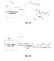
- Fig. 1Bis a schematic illustration of a bipolar electrosurgical system 3 according to the present disclosure.
- the system 3includes a bipolar electrosurgical forceps 10 having one or more electrodes for treating tissue of a patient P.
- the electrosurgical forceps 10include opposing jaw members having an active electrode 14 and a return electrode 16, respectively, disposed therein.
- the active electrode 14 and the return electrode 16are connected to the generator 20 through cable 18, which includes the supply and return lines 4, 8 coupled to the active and return terminals 112 and 114, respectively.
- the electrosurgical forceps 10are coupled to the generator 20 at a connector 21 having connections to the active and return terminals (e.g., pins) via a plug disposed at the end of the cable 18, wherein the plug includes contacts from the supply and return lines 4, 8.
- Fig. 2is a schematic block diagram of the generator 20 shown in Fig. 1 for use with an electrosurgical system according to an embodiment of the present disclosure.
- generator 20includes a square wave generator 100, active terminal 112, return terminal 114, sensor 122 and controller 124.
- Square wave generator 100is operatively coupled to active terminal 112 to provide electrosurgical energy in the form of a square wave to an electrosurgical instrument.
- the active terminal 112generates either continuous or pulsed square waveforms of high RF energy.
- the active terminal 112is configured to generate a plurality of waveforms having various duty cycles, peak voltages, crest factors, and other suitable parameters. Certain types of waveforms are suitable for specific electrosurgical modes.
- the active terminal 112generates a 100% duty cycle sinusoidal waveform in cut mode, which is best suited for ablating, fusing and dissecting tissue and a 1-25% duty cycle waveform in coagulation mode, which is best used for cauterizing tissue to stop bleeding.
- the generator 20may implement a closed and/or open loop control schemes that include a sensor circuit 122 having a plurality of sensors measuring a variety of tissue and energy properties (e.g., tissue impedance, tissue temperature, output current and/or voltage, etc.), and providing feedback to the controller 124.
- a current sensorcan be disposed at either the active or return current path or both and voltage can be sensed at the active electrode(s).
- the controller 124then transmits appropriate signals to the square wave generator 100, which then adjusts AC or DC power supply, respectively, by using a maximum allowable energy that varies according to the selected mode.
- the controller 124also receives input signals from the input controls of the generator 20 or the instrument 2.
- the controller 124utilizes the input signals to adjust power output by the generator 20 and/or performs other control functions thereon.
- the sensor circuit 122measures the electrical current (I) and voltage (V) supplied by the active terminal 112 in real time to characterize the electrosurgical process during application of electrosurgical energy to tissue. This allows for the measured electrical properties to be used as dynamic input control variables to achieve feedback control.
- the sensor circuit 122also measures properties of the current and voltage waveforms and determines the shape thereof.
- the controller 124includes a microprocessor operably connected to a memory, which may be volatile type memory (e.g., RAM) and/or non-volatile type memory (e.g., flash media, disk media, etc.).
- the controller 124includes an output port that is operably connected to the square wave generator 100 allowing the controller 124 to control the output of the generator 20 according to either open and/or closed control loop schemes.
- the microprocessormay be substituted by any logic processor or analog circuitry (e.g., control circuit) adapted to perform the calculations discussed herein.
- generator 20Because the output of generator 20 is a square wave, the RMS voltage and current is equal to the peak value of the square wave. As such, generator 20 does not need complicated sense hardware and/or signal processing that is usually required to accurately calculate RMS voltage and/or current for sinusoidal waveforms. Therefore, generator 20 has fewer components than the typical electrosurgical generator. Further, because the output of generator 20 is a square wave, generator 20 does not need large resonant components to shape the square wave.
- square wave generatorsare more efficient and can be made smaller than the typical electrosurgical generator in both the amplifier and sensor sections. Accordingly, a generator according to the above described embodiment may be incorporated into a portable handheld surgical device capable of being powered by a battery, battery pack or other portable power supply.
- Fig. 3is a schematic illustration of a generator 30 for use with an electrosurgical system according to another embodiment of the present disclosure.
- generator 30has a voltage source 102 that generates an output voltage that is transmitted to comparator 104.
- the output voltagemay be in the form of a sine wave, saw tooth wave or square wave.
- the output voltageis compared to a reference voltage at the negative input of comparator 104.
- Fig. 3shows the reference voltage as ground any other voltage may be used as a reference voltage.
- Comparator 104is supplied with a positive high voltage direct current (+HVDC) source 132 and a negative high voltage direct current (-HVDC) source 134. As such, when the output voltage from voltage source 102 is positive, the output of comparator 104 is +HVDC and when the output voltage from voltage source 102 is negative, the output of comparator 104 is - HVDC.
- the comparator outputis coupled to the active terminal 112 and provides energy in the form of a square wave to the electrosurgical instrument.
- Generator 30may implement a closed and/or open loop control schemes that include a sensor circuit 122 having a plurality of sensors measuring a variety of tissue and energy properties (e.g., tissue impedance, tissue temperature, output current and/or voltage, etc.), and providing feedback to the controller 124.
- a current sensorcan be disposed at either the active or return current path or both and voltage can be sensed at the active electrode(s).
- the controller 124then transmits appropriate signals to the voltage source 102, +HVDC source 132 and/or - HVDC source 134, which then adjusts AC or DC power supply, respectively, by using a maximum allowable energy that varies according to the selected mode,
- the controller 124also receives input signals from the input controls of the generator 30 or the instrument 2.
- the controller 124utilizes the input signals to adjust power output by the generator 30 and/or performs other control functions thereon.
- Fig. 4is a schematic illustration of a generator 40 according to another embodiment of the present disclosure.
- generator 40includes a waveform synthesizer 302 that generates waveforms having various duty cycles, peak voltages, crest factors, and other suitable parameters based on a selected mode for the electrosurgical device.
- Waveform synthesizer 302may include a pulse width modulated (PWM) controller that generates a PWM signal.
- PWMpulse width modulated
- Voltage gain stage 303amplifies the input voltage and provides the amplified voltage as an output to a class A/B amplifier 308.
- Voltage gain stage 303may include a transformer to provide patient isolation between the waveform synthesizer 302 and the patient.
- Voltage gain stage 303may also include a bias circuit that can be controlled by controller 124 to provide a bias voltage for the class A/B amplifier 308.
- the combined power amplifier formed by 303 and 308may be run open-loop or closed-loop.
- Amplifier 308may include two transistors 21 and 22 in a push-pull configuration and may be a part of the voltage gain stage 303 or be discrete components.
- the two transistors in amplifier 308may be bipolar transistors, field-effect transistors or laterally diffused metal oxide semiconductors.
- Generator 40also includes a sensor circuit 122 that measures the electrical current (I) and voltage (V) supplied by the active terminal 112 in real time to characterize the electrosurgical process for a predetermined sampling period.
- Sensor circuit 122provides a feedback signal to controller 124.
- Controller 124analyzes the feedback signal and controls the output of the waveform synthesizer 302, +HVDC source 132 and -HVDC source 132 based on the feedback signal.
- Fig. 5is a schematic illustration of a generator 50 according to another embodiment of the present disclosure.
- generator 50includes switching amplifier 504 in a push-pull configuration that generates waveforms having various duty cycles, peak voltages, crest factors, and other suitable parameters based on a selected mode for the electrosurgical device.
- Switching amplifier 504may include two transistors in a push-pull configuration.
- the two transistors in switching amplifier 504may be bipolar transistors, field-effect transistors or laterally diffused metal oxide semiconductors,
- the output of switching amplifier 504is fed into transformer 502.
- Transformer 502receives an input voltage from positive high voltage direct current (+HVDC) source 132 and provides an output voltage to active terminal 112.
- HVDCpositive high voltage direct current
- Generator 50also includes a sensor circuit 122 that measures the electrical current (I) and voltage (V) supplied by the active terminal 112 in real time to characterize the electrosurgical process for a predetermined sampling period.
- Sensor circuit 122provides a feedback signal to controller 124.
- Controller 124analyzes the feedback signal and controls the output of the switching amplifier 504 based on the feedback signal.
- Fig. 6is a schematic illustration of a generator 60 according to another embodiment of the present disclosure
- generator 60includes switching amplifier 604 in a full-bridge configuration that generates waveforms having various duty cycles, peak voltages, crest factors, and other suitable parameters based on a selected mode for the electrosurgical device.
- Switching amplifier 604may include four transistors that may be bipolar transistors, field-effect transistors or laterally diffused metal oxide semiconductors. The output of switching amplifier 604 is fed into transformer 602. Transformer 602 receives the input voltage and provides an output voltage to active terminal 112.
- Generator 60also includes a sensor circuit 122 that measures the electrical current (I) and voltage (V) supplied by the active terminal 112 in real time to characterize the electrosurgical process for a predetermined sampling period.
- Sensor circuit 122provides a feedback signal to controller 124.
- Controller 124analyzes the feedback signal and controls the output of the switching amplifier 604 based on the feedback signal.
- the generators described above with regard to Figs. 2-6include suitable input controls (e.g., buttons, activators, switches, touch screen, etc.) for controlling the generator.
- the generatormay include one or more display screens for providing the user with variety of output information (e.g., intensity settings, treatment complete indicators, etc.).
- the controlsallow the user to adjust power of the RF energy, waveform, as well as the level of maximum arc energy allowed which varies depending on desired tissue effects and other parameters to achieve the desired waveform suitable for a particular task (e.g., coagulating, tissue sealing, intensity setting, etc.).
- the instrument 2may also include a plurality of input controls that may be redundant with certain input controls of the generator. Placing the input controls at the instrument 2 allows for easier and faster modification of RF energy parameters during the surgical procedure without requiring interaction with the generator.
- the generatormay include a plurality of connectors to accommodate various types of electrosurgical instruments (e.g., instrument 2, electrosurgical forceps 10, etc.). Further, the generator may operate in monopolar or bipolar modes by including a switching mechanism (e.g., relays) to switch the supply of RF energy between the connectors, such that, for instance, when the instrument 2 is connected to the generator, only the monopolar plug receives RF energy.
- a switching mechanisme.g., relays
- Using square waves for treating tissuehas many advantages over using sinusoidal waves.
- Square waves generatorsdo not require additional resonant components to shape the waveform. Accordingly, a generator using a square wave output topology has a smaller implementation and a smaller component count than a generator that outputs a sinusoidal wave.
- complicated sensing hardware and/or signal processingmay be required to calculate the RMS voltage and/or current. For example, to calculate the RMS voltage of a sinusoidal wave, multiple samples of the voltage waveform have to be measured and then applied to complicated digital signal processing algorithms to obtain the RMS voltage value.
- a square wave outputa single sample may be used to obtain the RMS voltage value because the peak voltage value is equal to RMS voltage in a square wave.
- the simplified sensing method associated with square wave outputsreduces algorithm complexity thereby reducing required processor power and hardware costs.
- arcingmay be caused by high peak voltage and tends to have a negative impact on electrosurgical performance.
- Sinusoidal waveformshave a higher peak voltage compared to square waves with the same RMS value. For example, consider a waveform having a 100V RMS value. For a square wave output, the peak voltage would equal the RMS voltage so the peak value would be 100V. However, for a pure sinusoidal waveform, the peak voltage is equal to 1.414 times the RMS value so the peak voltage would be 141.4V. This discrepancy increases with the crest factor of the sinusoidal waveform. Accordingly, the lower peak voltage of the square wave output reduces the risk of arcing and improves performance of the electrosurgical device.
Landscapes
- Health & Medical Sciences (AREA)
- Surgery (AREA)
- Engineering & Computer Science (AREA)
- Life Sciences & Earth Sciences (AREA)
- Biomedical Technology (AREA)
- Otolaryngology (AREA)
- Nuclear Medicine, Radiotherapy & Molecular Imaging (AREA)
- Plasma & Fusion (AREA)
- Physics & Mathematics (AREA)
- Heart & Thoracic Surgery (AREA)
- Medical Informatics (AREA)
- Molecular Biology (AREA)
- Animal Behavior & Ethology (AREA)
- General Health & Medical Sciences (AREA)
- Public Health (AREA)
- Veterinary Medicine (AREA)
- Surgical Instruments (AREA)
Description
- The present disclosure relates to systems for providing energy to biological tissue and, more particularly, to an apparatus that utilizes square waves to deliver energy to biological tissue.
- Energy-based tissue treatment is well known in the art. Various types of energy (e.g., electrical, ultrasonic, microwave, cryogenic, thermal, laser, etc.) are applied to tissue to achieve a desired result. Electrosurgery involves application of high radio frequency electrical current to a surgical site to cut, ablate, coagulate or seal tissue. In monopolar electrosurgery, a source or active electrode delivers radio frequency energy from the electrosurgical generator to the tissue and a return electrode carries the current back to the generator. In monopolar electrosurgery, the source electrode is typically part of the surgical instrument held by the surgeon and applied to the tissue to be treated. A patient return electrode is placed remotely from the active electrode to carry the current back to the generator.
- Ablation is most commonly a monopolar procedure that is particularly useful in the field of cancer treatment, where one or more RF ablation needle electrodes (usually having elongated cylindrical geometry) are inserted into a living body and placed in the tumor region of an affected organ. A typical form of such needle electrodes incorporates an insulated sheath from which an exposed (uninsulated) tip extends. When RF energy is provided between the return electrode and the inserted ablation electrode, RF current flows from the needle electrode through the body. Typically, the current density is very high near the tip of the needle electrode, which tends to heat and destroy surrounding tissue.
- In bipolar electrosurgery, one of the electrodes of the hand-held instrument functions as the active electrode and the other as the return electrode. The return electrode is placed in close proximity to the active electrode such that an electrical circuit is formed between the two electrodes (e.g., electrosurgical forceps). In this manner, the applied electrical current is limited to the body tissue positioned immediately adjacent the electrodes. When the electrodes are sufficiently separated from one another, the electrical circuit is open and thus inadvertent contact with body tissue with either of the separated electrodes does not cause current to flow.
- Typically, sinusoidal waveforms are used to deliver energy for a desired tissue effect in electrosurgical and vessel sealing applications. Creating sinusoidal waveforms requires the use of low harmonic content linear drive or resonant switching amplifier topologies. However, linear drive electronics, which use linear components such as resistors, capacitors and inductors, tend to be inefficient due to the power loss caused by such linear components. With regard to resonant amplifier topologies, such topologies require large resonant components to shape the output waveform.
- Further, in order to achieve excellent tissue sealing performance, it is important to monitor the impedance of the tissue to which energy is being applied. The impedance is calculated by measuring the root mean square (RMS) voltage and current of the radio frequency (RF) energy output to calculate the tissue impedance. However, with sinusoidal waveforms, complicated sensing hardware and/or signal processing is required to accurately calculate RAMS voltage and/or current. Further, sinusoidal waveforms tend to have a peak voltage that is 1.414 times the RMS voltage of the waveform. The higher peak voltage may have a negative impact on certain tissue treatments.
US 2003/0181898 A1 describes an electrosurgical generator that comprises a circuit and method to produce a filtering technique that utilizes an output transformer as the inductive element of the filter and places two capacitors on the output of the transformer to produce the desired filtering. The output filter configuration eliminates the use of power inductors and still creates the filtering required in electrosurgical applications to generate a sinusoidal output. The filter utilizes the inductive properties of the output transformer along with several capacitors to form the band-pass filter.- According to a first aspect of the invention, there is provided a square wave generator suitable for use with an electrosurgical instrument according to
claim 1. - According to a second aspect of the invention, there is provided a square wave generator suitable for use with an electrosurgical instrument according to
claim 3. - According to a third aspect of the invention, there is provided a square wave generator suitable for use with an electrosurgical instrument according to claim 7.
- The above and other aspects, features, and advantages of the present disclosure will become more apparent in light of the following detailed description when taken in conjunction with the accompanying drawings in which:
Figs. 1A-1B are schematic block diagrams of an electrosurgical system according to the present disclosure for use with various instrument types;Fig. 2 is a schematic block diagram of a generator according to an embodiment of the present disclosure;Fig, 3 is a schematic diagram of a generator according to another embodiments of the present disclosure;Fig. 4 is a schematic diagram of a generator according to another embodiment of the present disclosure;Fig. 5 is a schematic diagram of a generator according to another embodiment of the present disclosure; andFig. 6 is a schematic diagram of a generator according to another embodiment of the present disclosure.- Particular embodiments of the present disclosure are described hereinbelow with reference to the accompanying drawings; however, it is to be understood that the disclosed embodiments are merely exemplary of the disclosure, which may be embodied in various form. Well-known functions or constructions are not described in detail to avoid obscuring the present disclosure in unnecessary detail. Therefore, specific structural and functional details disclosed herein are not to be interpreted as limiting, but merely as a basis for the claims and as a representative basis for teaching one skilled in the art to variously employ the present disclosure in virtually any appropriately detailed structure. Like reference numerals may refer to similar or identical elements throughout the description of the figures.
- The following describes a square wave generator suitable for use with an electrosurgical device. In one embodiment, the square wave generator includes a voltage source configured to output a waveform and a comparator operatively coupled to the voltage source and configured to output energy in the form of a square wave, The generator may also include at least one sensor configured to sense an operational parameter of the energy outputted from the comparator and to provide a sensor signal corresponding thereto, and a controller adapted to receive the at least one sensor signal and in response thereto control the voltage source.
- The square wave generator may also include a positive high voltage direct current source coupled to the comparator and a negative high voltage direct current source coupled to the comparator. The controller may control the output of the positive high voltage direct current source and the negative high voltage direct current source in response to the at least one sensor signal to control the outputs of the square wave generator.
- The operational parameter sensed by the circuit may be peak voltage or current.
- In another embodiment of the present disclosure, a square wave generator suitable for use with an electrosurgical device includes a waveform synthesizer configured to output a waveform and an amplifier operatively coupled to the waveform synthesizer and configured to output energy in the form of a square wave. The generator may also include at least one sensor configured to sense an operational parameter of the energy outputted from the comparator and to provide a sensor signal corresponding thereto, and a controller adapted to receive the at least one sensor signal and in response thereto, control the voltage source.
- The square wave generator may also include a positive high voltage direct current source coupled to the comparator and a negative high voltage direct current source coupled to the comparator. The controller may control the output of the positive high voltage direct current source and the negative high voltage direct current source in response to the at least one sensor signal to control the output of the square wave generator.
- The operational parameter sensed by the circuit may be peak voltage or current.
- The amplifier may include at least two gain elements arranged in a push-pull configuration. The at least two gain elements are selected from the group consisting of bipolar transistors, field-effect transistors, and laterally diffused metal oxide semiconductors.
- The square wave generator may also have a gain stage coupled between the waveform synthesizer and the amplifier. The gain stage may include a transformer.
- The generator according to the present disclosure can perform ablation, monopolar and bipolar electrosurgical procedures, including vessel sealing procedures. The generator may include a plurality of outputs for interfacing with various electrosurgical instruments (e.g., a monopolar active electrode, return electrode, bipolar electrosurgical forceps, footswitch, etc.). Further, the generator includes electronic circuitry configured for generating radio frequency power specifically suited for various electrosurgical modes (e.g., cutting, blending, division, etc.) and procedures (e.g., monopolar, bipolar, vessel sealing).
Fig. 1A is a schematic illustration of a monopolarelectrosurgical system 1 according to one embodiment of the present disclosure. Thesystem 1 includes anelectrosurgical instrument 2. having one or more electrodes for treating tissue of a patient P. Theinstrument 2 is a monopolar type instrument including one or more active electrodes (e.g., electrosurgical cutting probe, ablation electrode(s), etc.). Electrosurgical RF energy is supplied to theinstrument 2 by agenerator 20 via a supply line 4, which is connected to an active terminal (Fig. 2 ) of thegenerator 20, allowing theinstrument 2 to coagulate, ablate and/or otherwise treat tissue. The energy is returned to thegenerator 20 through a return electrode 6 via areturn line 8 at a return terminal (Fig. 2 ) of thegenerator 20. The active terminal and the return terminal are connectors configured to interface with plugs (not explicitly shown) of theinstrument 2 and the return electrode 6, which are disposed at the ends of the supply line 4 and thereturn line 8, respectively.- The
system 1 may include a plurality of return electrodes 6 that are arranged to minimize the chances of tissue damage by maximizing the overall contact area with the patient P. In addition, thegenerator 20 and the return electrode 6 may be configured for monitoring so-called "tissue-to-patient" contact to insure that sufficient contact exists therebetween to further minimize chances of tissue damage. In one embodiment, the active electrode 6 may be used to operate in a liquid environment, wherein the tissue is submerged in an electrolyte solution. - The
generator 20 includes suitable input controls (e.g., buttons, activators, switches, touch screen, etc.) for controlling thegenerator 20. In addition, thegenerator 20 may include one or more display screens for providing the user with variety of output information (e.g., intensity settings, treatment complete indicators, etc.). The controls allow the user to adjust power of the RF energy, waveform, as well as the level of maximum arc energy allowed which varies depending on desired tissue effects and other parameters to achieve the desired waveform suitable for a particular task (e.g., coagulating, tissue sealing, intensity setting, etc.). Theinstrument 2 may also include a plurality of input controls that may be redundant with certain input controls of thegenerator 20. Placing the input controls at theinstrument 2 allows for easier and faster modification of RF energy parameters during the surgical procedure without requiring interaction with thegenerator 20. Fig. 1B is a schematic illustration of abipolar electrosurgical system 3 according to the present disclosure. Thesystem 3 includes a bipolarelectrosurgical forceps 10 having one or more electrodes for treating tissue of a patient P. Theelectrosurgical forceps 10 include opposing jaw members having an active electrode 14 and areturn electrode 16, respectively, disposed therein. The active electrode 14 and thereturn electrode 16 are connected to thegenerator 20 throughcable 18, which includes the supply andreturn lines 4, 8 coupled to the active and returnterminals electrosurgical forceps 10 are coupled to thegenerator 20 at aconnector 21 having connections to the active and return terminals (e.g., pins) via a plug disposed at the end of thecable 18, wherein the plug includes contacts from the supply andreturn lines 4, 8.Fig. 2 is a schematic block diagram of thegenerator 20 shown inFig. 1 for use with an electrosurgical system according to an embodiment of the present disclosure. As shown inFig. 2 ,generator 20 includes asquare wave generator 100,active terminal 112, return terminal 114,sensor 122 andcontroller 124.Square wave generator 100 is operatively coupled toactive terminal 112 to provide electrosurgical energy in the form of a square wave to an electrosurgical instrument. In particular, theactive terminal 112 generates either continuous or pulsed square waveforms of high RF energy. Theactive terminal 112 is configured to generate a plurality of waveforms having various duty cycles, peak voltages, crest factors, and other suitable parameters. Certain types of waveforms are suitable for specific electrosurgical modes. For instance, theactive terminal 112 generates a 100% duty cycle sinusoidal waveform in cut mode, which is best suited for ablating, fusing and dissecting tissue and a 1-25% duty cycle waveform in coagulation mode, which is best used for cauterizing tissue to stop bleeding.- The
generator 20 may implement a closed and/or open loop control schemes that include asensor circuit 122 having a plurality of sensors measuring a variety of tissue and energy properties (e.g., tissue impedance, tissue temperature, output current and/or voltage, etc.), and providing feedback to thecontroller 124. A current sensor can be disposed at either the active or return current path or both and voltage can be sensed at the active electrode(s). Thecontroller 124 then transmits appropriate signals to thesquare wave generator 100, which then adjusts AC or DC power supply, respectively, by using a maximum allowable energy that varies according to the selected mode. Thecontroller 124 also receives input signals from the input controls of thegenerator 20 or theinstrument 2. Thecontroller 124 utilizes the input signals to adjust power output by thegenerator 20 and/or performs other control functions thereon. - When electrosurgical energy is applied to tissue, the impedance of the tissue changes. The
sensor circuit 122 measures the electrical current (I) and voltage (V) supplied by theactive terminal 112 in real time to characterize the electrosurgical process during application of electrosurgical energy to tissue. This allows for the measured electrical properties to be used as dynamic input control variables to achieve feedback control. The current and voltage values may also be used to derive other electrical parameters, such as power (P=V*I) and impedance (Z=V/I). Thesensor circuit 122 also measures properties of the current and voltage waveforms and determines the shape thereof. - The
controller 124 includes a microprocessor operably connected to a memory, which may be volatile type memory (e.g., RAM) and/or non-volatile type memory (e.g., flash media, disk media, etc.). Thecontroller 124 includes an output port that is operably connected to thesquare wave generator 100 allowing thecontroller 124 to control the output of thegenerator 20 according to either open and/or closed control loop schemes. Those skilled in the art will appreciate that the microprocessor may be substituted by any logic processor or analog circuitry (e.g., control circuit) adapted to perform the calculations discussed herein. - Because the output of
generator 20 is a square wave, the RMS voltage and current is equal to the peak value of the square wave. As such,generator 20 does not need complicated sense hardware and/or signal processing that is usually required to accurately calculate RMS voltage and/or current for sinusoidal waveforms. Therefore,generator 20 has fewer components than the typical electrosurgical generator. Further, because the output ofgenerator 20 is a square wave,generator 20 does not need large resonant components to shape the square wave. - Additionally, square wave generators are more efficient and can be made smaller than the typical electrosurgical generator in both the amplifier and sensor sections. Accordingly, a generator according to the above described embodiment may be incorporated into a portable handheld surgical device capable of being powered by a battery, battery pack or other portable power supply.
Fig. 3 is a schematic illustration of agenerator 30 for use with an electrosurgical system according to another embodiment of the present disclosure. As shown inFig. 3 ,generator 30 has avoltage source 102 that generates an output voltage that is transmitted tocomparator 104. The output voltage may be in the form of a sine wave, saw tooth wave or square wave. The output voltage is compared to a reference voltage at the negative input ofcomparator 104. AlthoughFig. 3 shows the reference voltage as ground any other voltage may be used as a reference voltage.Comparator 104 is supplied with a positive high voltage direct current (+HVDC)source 132 and a negative high voltage direct current (-HVDC)source 134. As such, when the output voltage fromvoltage source 102 is positive, the output ofcomparator 104 is +HVDC and when the output voltage fromvoltage source 102 is negative, the output ofcomparator 104 is - HVDC. The comparator output is coupled to theactive terminal 112 and provides energy in the form of a square wave to the electrosurgical instrument.Generator 30 may implement a closed and/or open loop control schemes that include asensor circuit 122 having a plurality of sensors measuring a variety of tissue and energy properties (e.g., tissue impedance, tissue temperature, output current and/or voltage, etc.), and providing feedback to thecontroller 124. A current sensor can be disposed at either the active or return current path or both and voltage can be sensed at the active electrode(s). Thecontroller 124 then transmits appropriate signals to thevoltage source 102, +HVDC source 132 and/or -HVDC source 134, which then adjusts AC or DC power supply, respectively, by using a maximum allowable energy that varies according to the selected mode, Thecontroller 124 also receives input signals from the input controls of thegenerator 30 or theinstrument 2. Thecontroller 124 utilizes the input signals to adjust power output by thegenerator 30 and/or performs other control functions thereon.Fig. 4 is a schematic illustration of agenerator 40 according to another embodiment of the present disclosure. As shown inFig. 4 ,generator 40 includes awaveform synthesizer 302 that generates waveforms having various duty cycles, peak voltages, crest factors, and other suitable parameters based on a selected mode for the electrosurgical device.Waveform synthesizer 302 may include a pulse width modulated (PWM) controller that generates a PWM signal.- The output of
waveform synthesizer 302 is fed intovoltage gain stage 303.Voltage gain stage 303 amplifies the input voltage and provides the amplified voltage as an output to a class A/B amplifier 308.Voltage gain stage 303 may include a transformer to provide patient isolation between thewaveform synthesizer 302 and the patient.Voltage gain stage 303 may also include a bias circuit that can be controlled bycontroller 124 to provide a bias voltage for the class A/B amplifier 308. The combined power amplifier formed by 303 and 308 may be run open-loop or closed-loop. Amplifier 308 may include twotransistors 21 and 22 in a push-pull configuration and may be a part of thevoltage gain stage 303 or be discrete components. The two transistors inamplifier 308 may be bipolar transistors, field-effect transistors or laterally diffused metal oxide semiconductors. When a positive voltage is applied to the base of Q1, a high positive voltage from +HVDC source 132 is supplied to theactive terminal 112. When a negative voltage is applied to the base of Q2, a high negative voltage from -HVDC source 134 is supplied toactive terminal 112.Generator 40 also includes asensor circuit 122 that measures the electrical current (I) and voltage (V) supplied by theactive terminal 112 in real time to characterize the electrosurgical process for a predetermined sampling period.Sensor circuit 122 provides a feedback signal tocontroller 124.Controller 124 analyzes the feedback signal and controls the output of thewaveform synthesizer 302, +HVDC source 132 and -HVDC source 132 based on the feedback signal.Fig. 5 is a schematic illustration of agenerator 50 according to another embodiment of the present disclosure. As shown inFig. 5 ,generator 50 includes switchingamplifier 504 in a push-pull configuration that generates waveforms having various duty cycles, peak voltages, crest factors, and other suitable parameters based on a selected mode for the electrosurgical device.Switching amplifier 504 may include two transistors in a push-pull configuration. The two transistors in switchingamplifier 504 may be bipolar transistors, field-effect transistors or laterally diffused metal oxide semiconductors, The output of switchingamplifier 504 is fed intotransformer 502.Transformer 502 receives an input voltage from positive high voltage direct current (+HVDC)source 132 and provides an output voltage toactive terminal 112.Generator 50 also includes asensor circuit 122 that measures the electrical current (I) and voltage (V) supplied by theactive terminal 112 in real time to characterize the electrosurgical process for a predetermined sampling period.Sensor circuit 122 provides a feedback signal tocontroller 124.Controller 124 analyzes the feedback signal and controls the output of the switchingamplifier 504 based on the feedback signal.Fig. 6 is a schematic illustration of agenerator 60 according to another embodiment of the present disclosure, As shown inFig. 6 ,generator 60 includes switchingamplifier 604 in a full-bridge configuration that generates waveforms having various duty cycles, peak voltages, crest factors, and other suitable parameters based on a selected mode for the electrosurgical device.Switching amplifier 604 may include four transistors that may be bipolar transistors, field-effect transistors or laterally diffused metal oxide semiconductors. The output of switchingamplifier 604 is fed intotransformer 602.Transformer 602 receives the input voltage and provides an output voltage toactive terminal 112.Generator 60 also includes asensor circuit 122 that measures the electrical current (I) and voltage (V) supplied by theactive terminal 112 in real time to characterize the electrosurgical process for a predetermined sampling period.Sensor circuit 122 provides a feedback signal tocontroller 124.Controller 124 analyzes the feedback signal and controls the output of the switchingamplifier 604 based on the feedback signal.- The generators described above with regard to
Figs. 2-6 include suitable input controls (e.g., buttons, activators, switches, touch screen, etc.) for controlling the generator. In addition, the generator may include one or more display screens for providing the user with variety of output information (e.g., intensity settings, treatment complete indicators, etc.). The controls allow the user to adjust power of the RF energy, waveform, as well as the level of maximum arc energy allowed which varies depending on desired tissue effects and other parameters to achieve the desired waveform suitable for a particular task (e.g., coagulating, tissue sealing, intensity setting, etc.). Theinstrument 2 may also include a plurality of input controls that may be redundant with certain input controls of the generator. Placing the input controls at theinstrument 2 allows for easier and faster modification of RF energy parameters during the surgical procedure without requiring interaction with the generator. - The generator may include a plurality of connectors to accommodate various types of electrosurgical instruments (e.g.,
instrument 2,electrosurgical forceps 10, etc.). Further, the generator may operate in monopolar or bipolar modes by including a switching mechanism (e.g., relays) to switch the supply of RF energy between the connectors, such that, for instance, when theinstrument 2 is connected to the generator, only the monopolar plug receives RF energy. - Using square waves for treating tissue has many advantages over using sinusoidal waves. Square waves generators do not require additional resonant components to shape the waveform. Accordingly, a generator using a square wave output topology has a smaller implementation and a smaller component count than a generator that outputs a sinusoidal wave. Further, when using sinusoidal waves, complicated sensing hardware and/or signal processing may be required to calculate the RMS voltage and/or current. For example, to calculate the RMS voltage of a sinusoidal wave, multiple samples of the voltage waveform have to be measured and then applied to complicated digital signal processing algorithms to obtain the RMS voltage value. On the other hand, with a square wave output, a single sample may be used to obtain the RMS voltage value because the peak voltage value is equal to RMS voltage in a square wave. The simplified sensing method associated with square wave outputs reduces algorithm complexity thereby reducing required processor power and hardware costs.
- Another consideration in certain tissue treatments using electrosurgical methods has to do with arcing between instrument jaws. Arcing may be caused by high peak voltage and tends to have a negative impact on electrosurgical performance. Sinusoidal waveforms have a higher peak voltage compared to square waves with the same RMS value. For example, consider a waveform having a 100V RMS value. For a square wave output, the peak voltage would equal the RMS voltage so the peak value would be 100V. However, for a pure sinusoidal waveform, the peak voltage is equal to 1.414 times the RMS value so the peak voltage would be 141.4V. This discrepancy increases with the crest factor of the sinusoidal waveform. Accordingly, the lower peak voltage of the square wave output reduces the risk of arcing and improves performance of the electrosurgical device.
- While several embodiments of the disclosure have been shown in the drawings and/or discussed herein, it is not intended that the disclosure be limited thereto, as it is intended that the disclosure be as broad in scope as the art will allow and that the specification be read likewise. Therefore, the above description should not be construed as limiting, but merely as exemplifications of particular embodiments. The claims can encompass embodiments in hardware, software, or a combination thereof. Those skilled in the art will envision other modifications within the scope of the claims appended hereto.
Claims (12)
- A square wave generator (20; 30) suitable for use with an electrosurgical instrument (2; 10), the square wave generator comprising:an active terminal (112) configured for connection to the electrosurgical instrument;a voltage source (102) configured to output a waveform;a comparator (104) operatively coupled to the voltage source (102) and to said active terminal (112) and configured to compare said waveform to a reference voltage to supply energy in the form of a square wave to said active terminal (112) for supply to said electrosurgical instrument;at least one sensor (122) configured to sense an operational parameter of the energy outputted from the comparator (104) and to provide a sensor signal corresponding thereto; anda controller (124) adapted to receive the at least one sensor signal and in response thereto controls the voltage source.
- The square wave generator according to claim 1, further comprising:a positive high voltage direct current source (132) coupled to the comparator (104); anda negative high voltage direct current source (134) coupled to the comparator, wherein the controller (124) is adapted to control the output of the positive high voltage direct current source (132) and the negative high voltage direct current source (134) in response to the at least one sensor signal to control the output of the square wave generator.
- A square wave generator (40) suitable for use with an electrosurgical instrument (2; 10), the square wave generator comprising:an active terminal (112) configured for connection to the electrosurgical instrument;a waveform synthesizer (302) configured to output a waveform;an amplifier (308) operatively coupled to the waveform synthesizer (302) and to said active terminal (112) and configured to amplify said waveform to output energy in the form of a square wave to said active terminal (112) for supply to said electrosurgical instrument;at least one sensor (122) configured to sense an operational parameter of the energy outputted from the amplifier and to provide a sensor signals corresponding thereto; anda controller (124) adapted to receive the at least one sensor signal and in response thereto control the waveform synthesizer (302).
- The square wave generator according to claim 3, further comprising:a positive high voltage direct current source (132) coupled to the amplifier (308); anda negative high voltage direct current source (134) coupled to the amplifier (308),wherein the controller (124) is adapted to control the output of the positive high voltage direct current source (132) and the negative high voltage direct current source (134) in response to the at least one sensor signal to control the output of the square wave generator.
- The square wave generator according to claim 3 or 4 further comprising a gain stage (303) coupled between the waveforms synthesizer (302) and the amplifier (308).
- The square wave generator according to claim 5, wherein the gain stage (303) further comprises a transformer.
- A square wave generator (50; 60) suitable for use with an electrosurgical instrument (2; 10), the square wave generator comprising:an active terminal (112) configured for connection to the electrosurgical instrument;an amplifier (504; 604) operatively coupled to a voltage source (132) and to the active terminal (112) and configured to output energy in the form of a square wave to said active terminal (112) in response to a control signal;at least one sensor (122) configured to sense an operational parameter of the energy outputted from the amplifier (504; 604) and to provide a sensor signal corresponding thereto; anda controller (124) adapted to receive the at least one sensor signal and in response thereto to generate said control signal to control the amplifier (504; 604) to produce said output energy in the form of a square wave at said active terminal (112) for supply to said electrosurgical instrument.
- The square wave generator according to claim 7, further comprising:a transformer (502; 602) coupled between the voltage source (132) and the amplifier (504; 604),wherein the controller (124) is adapted to control the current flow through the transformer (502; 602) in response to the at least one sensor signal to control the output of the square wave generator.
- The square wave generator according to any one of claims 3 to 8, wherein the amplifier (308; 504; 604) comprises at least two gain elements arranged in a push-pull configuration.
- The square wave generator according to claim 9, wherein the at least two gain elements are selected from the group consisting of bipolar transistors, field-effect transistors, and laterally diffused metal oxide semiconductors.
- The square wave generator according to any preceding claim, wherein the operational parameter is peak voltage.
- The square wave generator according to any one of claims 1 to 10, wherein the operational parameter is current.
Applications Claiming Priority (1)
| Application Number | Priority Date | Filing Date | Title |
|---|---|---|---|
| US12/700,856US9585709B2 (en) | 2010-02-05 | 2010-02-05 | Square wave for vessel sealing |
Publications (3)
| Publication Number | Publication Date |
|---|---|
| EP2353533A2 EP2353533A2 (en) | 2011-08-10 |
| EP2353533A3 EP2353533A3 (en) | 2012-07-25 |
| EP2353533B1true EP2353533B1 (en) | 2015-09-23 |
Family
ID=44064828
Family Applications (1)
| Application Number | Title | Priority Date | Filing Date |
|---|---|---|---|
| EP11153503.5AActiveEP2353533B1 (en) | 2010-02-05 | 2011-02-07 | Square wave for vessel sealing |
Country Status (5)
| Country | Link |
|---|---|
| US (1) | US9585709B2 (en) |
| EP (1) | EP2353533B1 (en) |
| JP (1) | JP2011161230A (en) |
| AU (1) | AU2011200472B2 (en) |
| CA (1) | CA2731002A1 (en) |
Families Citing this family (92)
| Publication number | Priority date | Publication date | Assignee | Title |
|---|---|---|---|---|
| US7364577B2 (en) | 2002-02-11 | 2008-04-29 | Sherwood Services Ag | Vessel sealing system |
| ES2262639T3 (en) | 2001-04-06 | 2006-12-01 | Sherwood Services Ag | SHUTTER AND DIVIDER OF GLASSES WITH BUMPER MEMBERS N OCONDUCTIVES. |
| US9848938B2 (en) | 2003-11-13 | 2017-12-26 | Covidien Ag | Compressible jaw configuration with bipolar RF output electrodes for soft tissue fusion |
| US7367976B2 (en) | 2003-11-17 | 2008-05-06 | Sherwood Services Ag | Bipolar forceps having monopolar extension |
| US7628791B2 (en) | 2005-08-19 | 2009-12-08 | Covidien Ag | Single action tissue sealer |
| CA2561034C (en) | 2005-09-30 | 2014-12-09 | Sherwood Services Ag | Flexible endoscopic catheter with an end effector for coagulating and transfecting tissue |
| US7722607B2 (en) | 2005-09-30 | 2010-05-25 | Covidien Ag | In-line vessel sealer and divider |
| US8475453B2 (en) | 2006-10-06 | 2013-07-02 | Covidien Lp | Endoscopic vessel sealer and divider having a flexible articulating shaft |
| US8142473B2 (en) | 2008-10-03 | 2012-03-27 | Tyco Healthcare Group Lp | Method of transferring rotational motion in an articulating surgical instrument |
| US8187273B2 (en) | 2009-05-07 | 2012-05-29 | Tyco Healthcare Group Lp | Apparatus, system, and method for performing an electrosurgical procedure |
| US8246618B2 (en) | 2009-07-08 | 2012-08-21 | Tyco Healthcare Group Lp | Electrosurgical jaws with offset knife |
| US8439911B2 (en) | 2009-09-09 | 2013-05-14 | Coviden Lp | Compact jaw including through bore pivot pin |
| US8133254B2 (en) | 2009-09-18 | 2012-03-13 | Tyco Healthcare Group Lp | In vivo attachable and detachable end effector assembly and laparoscopic surgical instrument and methods therefor |
| US8112871B2 (en) | 2009-09-28 | 2012-02-14 | Tyco Healthcare Group Lp | Method for manufacturing electrosurgical seal plates |
| US8480671B2 (en) | 2010-01-22 | 2013-07-09 | Covidien Lp | Compact jaw including split pivot pin |
| US8597295B2 (en) | 2010-04-12 | 2013-12-03 | Covidien Lp | Surgical instrument with non-contact electrical coupling |
| US8439913B2 (en) | 2010-04-29 | 2013-05-14 | Covidien Lp | Pressure sensing sealing plate |
| US10265118B2 (en) | 2010-05-04 | 2019-04-23 | Covidien Lp | Pinion blade drive mechanism for a laparoscopic vessel dissector |
| GB2480498A (en) | 2010-05-21 | 2011-11-23 | Ethicon Endo Surgery Inc | Medical device comprising RF circuitry |
| US11278345B2 (en) | 2010-05-25 | 2022-03-22 | Covidien Lp | Accurate jaw closure force in a catheter based instrument |
| US8672939B2 (en) | 2010-06-01 | 2014-03-18 | Covidien Lp | Surgical device for performing an electrosurgical procedure |
| US8409247B2 (en) | 2010-06-02 | 2013-04-02 | Covidien Lp | Apparatus for performing an electrosurgical procedure |
| US8469992B2 (en) | 2010-06-02 | 2013-06-25 | Covidien Lp | Apparatus for performing an electrosurgical procedure |
| US8491624B2 (en) | 2010-06-02 | 2013-07-23 | Covidien Lp | Apparatus for performing an electrosurgical procedure |
| US8469991B2 (en) | 2010-06-02 | 2013-06-25 | Covidien Lp | Apparatus for performing an electrosurgical procedure |
| US8585736B2 (en) | 2010-06-02 | 2013-11-19 | Covidien Lp | Apparatus for performing an electrosurgical procedure |
| US8430877B2 (en) | 2010-06-02 | 2013-04-30 | Covidien Lp | Apparatus for performing an electrosurgical procedure |
| US8409246B2 (en) | 2010-06-02 | 2013-04-02 | Covidien Lp | Apparatus for performing an electrosurgical procedure |
| US8491625B2 (en) | 2010-06-02 | 2013-07-23 | Covidien Lp | Apparatus for performing an electrosurgical procedure |
| US8540749B2 (en) | 2010-06-02 | 2013-09-24 | Covidien Lp | Apparatus for performing an electrosurgical procedure |
| US8647343B2 (en) | 2010-06-23 | 2014-02-11 | Covidien Lp | Surgical forceps for sealing and dividing tissue |
| US9028495B2 (en) | 2010-06-23 | 2015-05-12 | Covidien Lp | Surgical instrument with a separable coaxial joint |
| US8795269B2 (en) | 2010-07-26 | 2014-08-05 | Covidien Lp | Rotary tissue sealer and divider |
| US8814864B2 (en) | 2010-08-23 | 2014-08-26 | Covidien Lp | Method of manufacturing tissue sealing electrodes |
| US9005200B2 (en) | 2010-09-30 | 2015-04-14 | Covidien Lp | Vessel sealing instrument |
| US9017372B2 (en) | 2010-10-01 | 2015-04-28 | Covidien Lp | Blade deployment mechanisms for surgical forceps |
| US9655672B2 (en) | 2010-10-04 | 2017-05-23 | Covidien Lp | Vessel sealing instrument |
| US8932293B2 (en) | 2010-11-17 | 2015-01-13 | Covidien Lp | Method and apparatus for vascular tissue sealing with reduced energy consumption |
| US8945175B2 (en) | 2011-01-14 | 2015-02-03 | Covidien Lp | Latch mechanism for surgical instruments |
| US9113940B2 (en) | 2011-01-14 | 2015-08-25 | Covidien Lp | Trigger lockout and kickback mechanism for surgical instruments |
| US8900232B2 (en) | 2011-05-06 | 2014-12-02 | Covidien Lp | Bifurcated shaft for surgical instrument |
| US8939972B2 (en) | 2011-05-06 | 2015-01-27 | Covidien Lp | Surgical forceps |
| US8685009B2 (en) | 2011-05-16 | 2014-04-01 | Covidien Lp | Thread-like knife for tissue cutting |
| US8852185B2 (en) | 2011-05-19 | 2014-10-07 | Covidien Lp | Apparatus for performing an electrosurgical procedure |
| US9615877B2 (en) | 2011-06-17 | 2017-04-11 | Covidien Lp | Tissue sealing forceps |
| US8745840B2 (en) | 2011-07-11 | 2014-06-10 | Covidien Lp | Surgical forceps and method of manufacturing thereof |
| US9039732B2 (en) | 2011-07-11 | 2015-05-26 | Covidien Lp | Surgical forceps |
| US8852186B2 (en) | 2011-08-09 | 2014-10-07 | Covidien Lp | Microwave sensing for tissue sealing |
| US8845636B2 (en) | 2011-09-16 | 2014-09-30 | Covidien Lp | Seal plate with insulation displacement connection |
| US9333025B2 (en) | 2011-10-24 | 2016-05-10 | Ethicon Endo-Surgery, Llc | Battery initialization clip |
| USD680220S1 (en) | 2012-01-12 | 2013-04-16 | Coviden IP | Slider handle for laparoscopic device |
| US9192421B2 (en) | 2012-07-24 | 2015-11-24 | Covidien Lp | Blade lockout mechanism for surgical forceps |
| US9526564B2 (en) | 2012-10-08 | 2016-12-27 | Covidien Lp | Electric stapler device |
| US10729484B2 (en)* | 2013-07-16 | 2020-08-04 | Covidien Lp | Electrosurgical generator with continuously and arbitrarily variable crest factor |
| AU2013375909B2 (en) | 2013-08-07 | 2015-07-30 | Covidien Lp | Bipolar surgical instrument |
| AU2013397838B2 (en) | 2013-08-07 | 2018-08-16 | Covidien Lp | Bipolar surgical instrument with tissue stop |
| US10045812B2 (en) | 2014-08-11 | 2018-08-14 | Covidien Lp | Surgical instruments and methods for performing tonsillectomy and adenoidectomy procedures |
| US10159524B2 (en)* | 2014-12-22 | 2018-12-25 | Ethicon Llc | High power battery powered RF amplifier topology |
| US10363084B2 (en) | 2015-04-01 | 2019-07-30 | Covidien Lp | Interdigitation of waveforms for dual-output electrosurgical generators |
| WO2016183084A1 (en) | 2015-05-11 | 2016-11-17 | Stryker Corporation | System and method for driving an ultrasonic handpiece with a linear amplifier |
| US11446078B2 (en) | 2015-07-20 | 2022-09-20 | Megadyne Medical Products, Inc. | Electrosurgical wave generator |
| US10987159B2 (en) | 2015-08-26 | 2021-04-27 | Covidien Lp | Electrosurgical end effector assemblies and electrosurgical forceps configured to reduce thermal spread |
| US10959771B2 (en) | 2015-10-16 | 2021-03-30 | Ethicon Llc | Suction and irrigation sealing grasper |
| US10959806B2 (en) | 2015-12-30 | 2021-03-30 | Ethicon Llc | Energized medical device with reusable handle |
| US10426543B2 (en) | 2016-01-23 | 2019-10-01 | Covidien Lp | Knife trigger for vessel sealer |
| US10856934B2 (en) | 2016-04-29 | 2020-12-08 | Ethicon Llc | Electrosurgical instrument with electrically conductive gap setting and tissue engaging members |
| US10987156B2 (en) | 2016-04-29 | 2021-04-27 | Ethicon Llc | Electrosurgical instrument with electrically conductive gap setting member and electrically insulative tissue engaging members |
| US10188449B2 (en) | 2016-05-23 | 2019-01-29 | Covidien Lp | System and method for temperature enhanced irreversible electroporation |
| US10682154B2 (en) | 2016-08-02 | 2020-06-16 | Covidien Lp | Cutting mechanisms for surgical end effector assemblies, instruments, and systems |
| US10631887B2 (en) | 2016-08-15 | 2020-04-28 | Covidien Lp | Electrosurgical forceps for video assisted thoracoscopic surgery and other surgical procedures |
| US10751117B2 (en) | 2016-09-23 | 2020-08-25 | Ethicon Llc | Electrosurgical instrument with fluid diverter |
| US11033325B2 (en) | 2017-02-16 | 2021-06-15 | Cilag Gmbh International | Electrosurgical instrument with telescoping suction port and debris cleaner |
| US10799284B2 (en) | 2017-03-15 | 2020-10-13 | Ethicon Llc | Electrosurgical instrument with textured jaws |
| US11497546B2 (en) | 2017-03-31 | 2022-11-15 | Cilag Gmbh International | Area ratios of patterned coatings on RF electrodes to reduce sticking |
| US10973567B2 (en) | 2017-05-12 | 2021-04-13 | Covidien Lp | Electrosurgical forceps for grasping, treating, and/or dividing tissue |
| US11172980B2 (en) | 2017-05-12 | 2021-11-16 | Covidien Lp | Electrosurgical forceps for grasping, treating, and/or dividing tissue |
| USD843574S1 (en) | 2017-06-08 | 2019-03-19 | Covidien Lp | Knife for open vessel sealer |
| USD854149S1 (en) | 2017-06-08 | 2019-07-16 | Covidien Lp | End effector for open vessel sealer |
| USD854684S1 (en) | 2017-06-08 | 2019-07-23 | Covidien Lp | Open vessel sealer with mechanical cutter |
| US11490951B2 (en) | 2017-09-29 | 2022-11-08 | Cilag Gmbh International | Saline contact with electrodes |
| US11484358B2 (en) | 2017-09-29 | 2022-11-01 | Cilag Gmbh International | Flexible electrosurgical instrument |
| US11033323B2 (en) | 2017-09-29 | 2021-06-15 | Cilag Gmbh International | Systems and methods for managing fluid and suction in electrosurgical systems |
| US11376062B2 (en) | 2018-10-12 | 2022-07-05 | Covidien Lp | Electrosurgical forceps |
| US11471211B2 (en) | 2018-10-12 | 2022-10-18 | Covidien Lp | Electrosurgical forceps |
| US11350982B2 (en) | 2018-12-05 | 2022-06-07 | Covidien Lp | Electrosurgical forceps |
| US11523861B2 (en) | 2019-03-22 | 2022-12-13 | Covidien Lp | Methods for manufacturing a jaw assembly for an electrosurgical forceps |
| US12402934B2 (en) | 2019-09-15 | 2025-09-02 | Covidien Lp | Electrosurgical instrument for grasping, treating, and/or dividing tissue incorporating thermal management feature |
| US11622804B2 (en) | 2020-03-16 | 2023-04-11 | Covidien Lp | Forceps with linear trigger mechanism |
| US12295641B2 (en) | 2020-07-01 | 2025-05-13 | Covidien Lp | Electrosurgical forceps with swivel action nerve probe |
| US11660109B2 (en) | 2020-09-08 | 2023-05-30 | Covidien Lp | Cutting elements for surgical instruments such as for use in robotic surgical systems |
| EP4066765B1 (en)* | 2021-03-31 | 2025-09-03 | Erbe Elektromedizin GmbH | Active electrosurgical instrument |
| US11957342B2 (en) | 2021-11-01 | 2024-04-16 | Cilag Gmbh International | Devices, systems, and methods for detecting tissue and foreign objects during a surgical operation |
Family Cites Families (93)
| Publication number | Priority date | Publication date | Assignee | Title |
|---|---|---|---|---|
| SU401367A1 (en) | 1971-10-05 | 1973-10-12 | Тернопольский государственный медицинский институт | BIAKTIVNYE ELECTRO SURGICAL INSTRUMENT |
| JPS5241593B2 (en)* | 1972-12-29 | 1977-10-19 | ||
| DE2415263A1 (en) | 1974-03-29 | 1975-10-02 | Aesculap Werke Ag | Surgical H.F. coagulation probe has electrode tongs - with exposed ends of insulated conductors forming tong-jaws |
| US4016886A (en)* | 1974-11-26 | 1977-04-12 | The United States Of America As Represented By The United States Energy Research And Development Administration | Method for localizing heating in tumor tissue |
| DE2514501A1 (en) | 1975-04-03 | 1976-10-21 | Karl Storz | Bipolar coagulation instrument for endoscopes - has two high frequency electrodes looped over central insulating piece |
| FR2315286A2 (en) | 1975-06-26 | 1977-01-21 | Lamidey Marcel | H.F. blood coagulating dissecting forceps - with adjustable stops to vary clamping space and circuit making contacts |
| US4034762A (en)* | 1975-08-04 | 1977-07-12 | Electro Medical Systems, Inc. | Vas cautery apparatus |
| US4211230A (en)* | 1978-07-31 | 1980-07-08 | Sybron Corporation | Electrosurgical coagulation |
| USD263020S (en)* | 1980-01-22 | 1982-02-16 | Rau Iii David M | Retractable knife |
| US4559943A (en)* | 1981-09-03 | 1985-12-24 | C. R. Bard, Inc. | Electrosurgical generator |
| US4878493A (en)* | 1983-10-28 | 1989-11-07 | Ninetronix Venture I | Hand-held diathermy apparatus |
| US4671274A (en) | 1984-01-30 | 1987-06-09 | Kharkovsky Nauchno-Issledovatelsky Institut Obschei I | Bipolar electrosurgical instrument |
| DE3423356C2 (en) | 1984-06-25 | 1986-06-26 | Berchtold Medizin-Elektronik GmbH & Co, 7200 Tuttlingen | Electrosurgical high frequency cutting instrument |
| US4657016A (en) | 1984-08-20 | 1987-04-14 | Garito Jon C | Electrosurgical handpiece for blades, needles and forceps |
| USD295893S (en)* | 1985-09-25 | 1988-05-24 | Acme United Corporation | Disposable surgical clamp |
| USD295894S (en)* | 1985-09-26 | 1988-05-24 | Acme United Corporation | Disposable surgical scissors |
| DE8712328U1 (en) | 1987-09-11 | 1988-02-18 | Jakoubek, Franz, 7201 Emmingen-Liptingen | Endoscopy forceps |
| JP2806511B2 (en) | 1990-07-31 | 1998-09-30 | 松下電工株式会社 | Manufacturing method of sintered alloy |
| US5190541A (en) | 1990-10-17 | 1993-03-02 | Boston Scientific Corporation | Surgical instrument and method |
| JP2951418B2 (en) | 1991-02-08 | 1999-09-20 | トキコ株式会社 | Sample liquid component analyzer |
| MX9702434A (en)* | 1991-03-07 | 1998-05-31 | Masimo Corp | Signal processing apparatus. |
| USD348930S (en)* | 1991-10-11 | 1994-07-19 | Ethicon, Inc. | Endoscopic stapler |
| US5902272A (en)* | 1992-01-07 | 1999-05-11 | Arthrocare Corporation | Planar ablation probe and method for electrosurgical cutting and ablation |
| US5964759A (en)* | 1992-10-27 | 1999-10-12 | Ortho Development Corporation | Electroconvergent cautery system |
| US6059781A (en)* | 1992-10-27 | 2000-05-09 | Yamanashi; William S. | Electroconvergent cautery system |
| DE4303882C2 (en) | 1993-02-10 | 1995-02-09 | Kernforschungsz Karlsruhe | Combination instrument for separation and coagulation for minimally invasive surgery |
| GB9309142D0 (en) | 1993-05-04 | 1993-06-16 | Gyrus Medical Ltd | Laparoscopic instrument |
| GB9322464D0 (en) | 1993-11-01 | 1993-12-22 | Gyrus Medical Ltd | Electrosurgical apparatus |
| US5396194A (en)* | 1993-11-19 | 1995-03-07 | Carver Corporation | Audio frequency power amplifiers |
| DE4403252A1 (en) | 1994-02-03 | 1995-08-10 | Michael Hauser | Instrument shaft for min. invasive surgery |
| GB9413070D0 (en) | 1994-06-29 | 1994-08-17 | Gyrus Medical Ltd | Electrosurgical apparatus |
| USD384413S (en)* | 1994-10-07 | 1997-09-30 | United States Surgical Corporation | Endoscopic suturing instrument |
| GB9425781D0 (en) | 1994-12-21 | 1995-02-22 | Gyrus Medical Ltd | Electrosurgical instrument |
| DE19506363A1 (en) | 1995-02-24 | 1996-08-29 | Frost Lore Geb Haupt | Non-invasive thermometry in organs under hyperthermia and coagulation conditions |
| DE19515914C1 (en) | 1995-05-02 | 1996-07-25 | Aesculap Ag | Tong or scissor-shaped surgical instrument |
| US6293942B1 (en) | 1995-06-23 | 2001-09-25 | Gyrus Medical Limited | Electrosurgical generator method |
| JPH0964727A (en)* | 1995-08-23 | 1997-03-07 | Toshiba Corp | Synchronous circuit |
| US5776130A (en) | 1995-09-19 | 1998-07-07 | Valleylab, Inc. | Vascular tissue sealing pressure control |
| DE19608716C1 (en) | 1996-03-06 | 1997-04-17 | Aesculap Ag | Bipolar surgical holding instrument |
| CA2221414C (en)* | 1996-03-18 | 2006-05-02 | 688726 Alberta Ltd. | Electrotherapy device |
| US5777519A (en)* | 1996-07-18 | 1998-07-07 | Simopoulos; Anastasios V. | High efficiency power amplifier |
| DE29616210U1 (en) | 1996-09-18 | 1996-11-14 | Olympus Winter & Ibe Gmbh, 22045 Hamburg | Handle for surgical instruments |
| US5923475A (en) | 1996-11-27 | 1999-07-13 | Eastman Kodak Company | Laser printer using a fly's eye integrator |
| US5891142A (en) | 1996-12-06 | 1999-04-06 | Eggers & Associates, Inc. | Electrosurgical forceps |
| USH2037H1 (en) | 1997-05-14 | 2002-07-02 | David C. Yates | Electrosurgical hemostatic device including an anvil |
| DE19738457B4 (en) | 1997-09-03 | 2009-01-02 | Celon Ag Medical Instruments | Method and device for in vivo deep coagulation of biological tissue volumes while sparing the tissue surface with high frequency alternating current |
| DE19751108A1 (en) | 1997-11-18 | 1999-05-20 | Beger Frank Michael Dipl Desig | Electrosurgical operation tool, especially for diathermy |
| EP0923907A1 (en) | 1997-12-19 | 1999-06-23 | Gyrus Medical Limited | An electrosurgical instrument |
| NL1009568C2 (en)* | 1998-07-06 | 2000-01-10 | Raitec B V I O | Device for treating patients using electromagnetic radiation. |
| US6385265B1 (en)* | 1998-08-04 | 2002-05-07 | Cypress Semiconductor Corp. | Differential charge pump |
| USD424694S (en)* | 1998-10-23 | 2000-05-09 | Sherwood Services Ag | Forceps |
| USD425201S (en)* | 1998-10-23 | 2000-05-16 | Sherwood Services Ag | Disposable electrode assembly |
| USD449886S1 (en)* | 1998-10-23 | 2001-10-30 | Sherwood Services Ag | Forceps with disposable electrode |
| DE19858512C1 (en) | 1998-12-18 | 2000-05-25 | Storz Karl Gmbh & Co Kg | Bipolar medical instrument for minimally invasive surgery for endoscopic operations; has mutually insulated leads passing through tubular shaft to conductor elements on linked jaw parts |
| GB9911956D0 (en) | 1999-05-21 | 1999-07-21 | Gyrus Medical Ltd | Electrosurgery system and method |
| GB9911954D0 (en) | 1999-05-21 | 1999-07-21 | Gyrus Medical Ltd | Electrosurgery system and instrument |
| US20030181898A1 (en)* | 1999-05-28 | 2003-09-25 | Bowers William J. | RF filter for an electrosurgical generator |
| GB9912625D0 (en) | 1999-05-28 | 1999-07-28 | Gyrus Medical Ltd | An electrosurgical generator and system |
| GB9912627D0 (en) | 1999-05-28 | 1999-07-28 | Gyrus Medical Ltd | An electrosurgical instrument |
| GB9913652D0 (en) | 1999-06-11 | 1999-08-11 | Gyrus Medical Ltd | An electrosurgical generator |
| DE10003020C2 (en) | 2000-01-25 | 2001-12-06 | Aesculap Ag & Co Kg | Bipolar barrel instrument |
| DE10027727C1 (en) | 2000-06-03 | 2001-12-06 | Aesculap Ag & Co Kg | Scissors-shaped or forceps-shaped surgical instrument |
| DE10045375C2 (en) | 2000-09-14 | 2002-10-24 | Aesculap Ag & Co Kg | Medical instrument |
| US6620157B1 (en)* | 2000-12-28 | 2003-09-16 | Senorx, Inc. | High frequency power source |
| USD457958S1 (en)* | 2001-04-06 | 2002-05-28 | Sherwood Services Ag | Vessel sealer and divider |
| USD457959S1 (en)* | 2001-04-06 | 2002-05-28 | Sherwood Services Ag | Vessel sealer |
| US7041096B2 (en)* | 2002-10-24 | 2006-05-09 | Synergetics Usa, Inc. | Electrosurgical generator apparatus |
| CA2505727A1 (en)* | 2002-11-13 | 2004-05-27 | Artemis Medical, Inc. | Devices and methods for controlling initial movement of an electrosurgical electrode |
| USD493888S1 (en)* | 2003-02-04 | 2004-08-03 | Sherwood Services Ag | Electrosurgical pencil with pistol grip |
| US20050015125A1 (en)* | 2003-03-14 | 2005-01-20 | Mioduski Paul C. | Hyperthermia treatment systems and methods |
| USD499181S1 (en)* | 2003-05-15 | 2004-11-30 | Sherwood Services Ag | Handle for a vessel sealer and divider |
| USD496997S1 (en)* | 2003-05-15 | 2004-10-05 | Sherwood Services Ag | Vessel sealer and divider |
| ITVI20030110A1 (en)* | 2003-06-06 | 2004-12-07 | Telea Electronic Eng Srl | ELECTRONIC SCALPEL. |
| US7499315B2 (en)* | 2003-06-11 | 2009-03-03 | Ovonyx, Inc. | Programmable matrix array with chalcogenide material |
| USD509297S1 (en)* | 2003-10-17 | 2005-09-06 | Tyco Healthcare Group, Lp | Surgical instrument |
| GB2409115B (en)* | 2003-12-09 | 2006-11-01 | Nujira Ltd | Transformer based voltage supply |
| USD541938S1 (en)* | 2004-04-09 | 2007-05-01 | Sherwood Services Ag | Open vessel sealer with mechanical cutter |
| DE102004026179B4 (en) | 2004-05-14 | 2009-01-22 | Erbe Elektromedizin Gmbh | Electrosurgical instrument |
| USD533942S1 (en)* | 2004-06-30 | 2006-12-19 | Sherwood Services Ag | Open vessel sealer with mechanical cutter |
| USD531311S1 (en)* | 2004-10-06 | 2006-10-31 | Sherwood Services Ag | Pistol grip style elongated dissecting and dividing instrument |
| USD535027S1 (en)* | 2004-10-06 | 2007-01-09 | Sherwood Services Ag | Low profile vessel sealing and cutting mechanism |
| USD525361S1 (en)* | 2004-10-06 | 2006-07-18 | Sherwood Services Ag | Hemostat style elongated dissecting and dividing instrument |
| USD541418S1 (en)* | 2004-10-06 | 2007-04-24 | Sherwood Services Ag | Lung sealing device |
| USD567943S1 (en)* | 2004-10-08 | 2008-04-29 | Sherwood Services Ag | Over-ratchet safety for a vessel sealing instrument |
| USD564662S1 (en)* | 2004-10-13 | 2008-03-18 | Sherwood Services Ag | Hourglass-shaped knife for electrosurgical forceps |
| DE102005038442B4 (en)* | 2005-08-12 | 2011-11-17 | Siemens Ag | Push-pull amplifier with transformer negative feedback |
| US7898288B2 (en)* | 2006-12-07 | 2011-03-01 | Integrated Device Technology, Inc. | Input termination for delay locked loop feedback with impedance matching |
| USD575395S1 (en)* | 2007-02-15 | 2008-08-19 | Tyco Healthcare Group Lp | Hemostat style elongated dissecting and dividing instrument |
| CN101677812B (en)* | 2007-03-23 | 2013-06-12 | 显著外科技术公司 | Surgical device and method of use thereof |
| USD575401S1 (en)* | 2007-06-12 | 2008-08-19 | Tyco Healthcare Group Lp | Vessel sealer |
| DE202007009317U1 (en) | 2007-06-26 | 2007-08-30 | Aesculap Ag & Co. Kg | Surgical instrument |
| WO2009078204A1 (en)* | 2007-12-14 | 2009-06-25 | Sharp Kabushiki Kaisha | Counter electrode drive circuit and counter electrode driving method |
| US8137345B2 (en)* | 2009-01-05 | 2012-03-20 | Peak Surgical, Inc. | Electrosurgical devices for tonsillectomy and adenoidectomy |
- 2010
- 2010-02-05USUS12/700,856patent/US9585709B2/enactiveActive
- 2011
- 2011-02-03CACA2731002Apatent/CA2731002A1/ennot_activeAbandoned
- 2011-02-04AUAU2011200472Apatent/AU2011200472B2/ennot_activeExpired - Fee Related
- 2011-02-04JPJP2011023376Apatent/JP2011161230A/ennot_activeWithdrawn
- 2011-02-07EPEP11153503.5Apatent/EP2353533B1/enactiveActive
Also Published As
| Publication number | Publication date |
|---|---|
| EP2353533A2 (en) | 2011-08-10 |
| JP2011161230A (en) | 2011-08-25 |
| US9585709B2 (en) | 2017-03-07 |
| US20110193608A1 (en) | 2011-08-11 |
| EP2353533A3 (en) | 2012-07-25 |
| AU2011200472A1 (en) | 2011-08-25 |
| AU2011200472B2 (en) | 2015-06-11 |
| CA2731002A1 (en) | 2011-08-05 |
Similar Documents
| Publication | Publication Date | Title |
|---|---|---|
| EP2353533B1 (en) | Square wave for vessel sealing | |
| US8779852B2 (en) | Class resonant-H electrosurgical generators | |
| US9522038B2 (en) | Crest factor enhancement in electrosurgical generators | |
| CN103635157B (en) | An electrosurgical device with real-time radiofrequency tissue energy control | |
| US8617154B2 (en) | Current-fed push-pull converter with passive voltage clamp | |
| EP2105102A2 (en) | Electrosurgical apparatus with predictive RF source control | |
| US8668690B2 (en) | Apparatus and method for optimal tissue separation | |
| EP2499983B1 (en) | Isolated current sensor | |
| US9522039B2 (en) | Crest factor enhancement in electrosurgical generators |
Legal Events
| Date | Code | Title | Description |
|---|---|---|---|
| PUAI | Public reference made under article 153(3) epc to a published international application that has entered the european phase | Free format text:ORIGINAL CODE: 0009012 | |
| AK | Designated contracting states | Kind code of ref document:A2 Designated state(s):AL AT BE BG CH CY CZ DE DK EE ES FI FR GB GR HR HU IE IS IT LI LT LU LV MC MK MT NL NO PL PT RO RS SE SI SK SM TR | |
| AX | Request for extension of the european patent | Extension state:BA ME | |
| RIC1 | Information provided on ipc code assigned before grant | Ipc:A61B 18/12 20060101AFI20120228BHEP | |
| PUAL | Search report despatched | Free format text:ORIGINAL CODE: 0009013 | |
| AK | Designated contracting states | Kind code of ref document:A3 Designated state(s):AL AT BE BG CH CY CZ DE DK EE ES FI FR GB GR HR HU IE IS IT LI LT LU LV MC MK MT NL NO PL PT RO RS SE SI SK SM TR | |
| AX | Request for extension of the european patent | Extension state:BA ME | |
| RIC1 | Information provided on ipc code assigned before grant | Ipc:A61B 18/12 20060101AFI20120619BHEP | |
| RAP1 | Party data changed (applicant data changed or rights of an application transferred) | Owner name:COVIDIEN LP | |
| 17P | Request for examination filed | Effective date:20121221 | |
| 17Q | First examination report despatched | Effective date:20130531 | |
| GRAP | Despatch of communication of intention to grant a patent | Free format text:ORIGINAL CODE: EPIDOSNIGR1 | |
| INTG | Intention to grant announced | Effective date:20150424 | |
| GRAS | Grant fee paid | Free format text:ORIGINAL CODE: EPIDOSNIGR3 | |
| GRAA | (expected) grant | Free format text:ORIGINAL CODE: 0009210 | |
| AK | Designated contracting states | Kind code of ref document:B1 Designated state(s):AL AT BE BG CH CY CZ DE DK EE ES FI FR GB GR HR HU IE IS IT LI LT LU LV MC MK MT NL NO PL PT RO RS SE SI SK SM TR | |
| REG | Reference to a national code | Ref country code:GB Ref legal event code:FG4D | |
| REG | Reference to a national code | Ref country code:CH Ref legal event code:EP | |
| REG | Reference to a national code | Ref country code:AT Ref legal event code:REF Ref document number:750770 Country of ref document:AT Kind code of ref document:T Effective date:20151015 | |
| REG | Reference to a national code | Ref country code:IE Ref legal event code:FG4D | |
| REG | Reference to a national code | Ref country code:DE Ref legal event code:R096 Ref document number:602011019950 Country of ref document:DE | |
| REG | Reference to a national code | Ref country code:FR Ref legal event code:PLFP Year of fee payment:6 | |
| REG | Reference to a national code | Ref country code:NL Ref legal event code:MP Effective date:20150923 | |
| PG25 | Lapsed in a contracting state [announced via postgrant information from national office to epo] | Ref country code:GR Free format text:LAPSE BECAUSE OF FAILURE TO SUBMIT A TRANSLATION OF THE DESCRIPTION OR TO PAY THE FEE WITHIN THE PRESCRIBED TIME-LIMIT Effective date:20151224 Ref country code:NO Free format text:LAPSE BECAUSE OF FAILURE TO SUBMIT A TRANSLATION OF THE DESCRIPTION OR TO PAY THE FEE WITHIN THE PRESCRIBED TIME-LIMIT Effective date:20151223 Ref country code:LV Free format text:LAPSE BECAUSE OF FAILURE TO SUBMIT A TRANSLATION OF THE DESCRIPTION OR TO PAY THE FEE WITHIN THE PRESCRIBED TIME-LIMIT Effective date:20150923 Ref country code:FI Free format text:LAPSE BECAUSE OF FAILURE TO SUBMIT A TRANSLATION OF THE DESCRIPTION OR TO PAY THE FEE WITHIN THE PRESCRIBED TIME-LIMIT Effective date:20150923 Ref country code:LT Free format text:LAPSE BECAUSE OF FAILURE TO SUBMIT A TRANSLATION OF THE DESCRIPTION OR TO PAY THE FEE WITHIN THE PRESCRIBED TIME-LIMIT Effective date:20150923 | |
| REG | Reference to a national code | Ref country code:LT Ref legal event code:MG4D | |
| REG | Reference to a national code | Ref country code:AT Ref legal event code:MK05 Ref document number:750770 Country of ref document:AT Kind code of ref document:T Effective date:20150923 | |
| PG25 | Lapsed in a contracting state [announced via postgrant information from national office to epo] | Ref country code:SE Free format text:LAPSE BECAUSE OF FAILURE TO SUBMIT A TRANSLATION OF THE DESCRIPTION OR TO PAY THE FEE WITHIN THE PRESCRIBED TIME-LIMIT Effective date:20150923 Ref country code:RS Free format text:LAPSE BECAUSE OF FAILURE TO SUBMIT A TRANSLATION OF THE DESCRIPTION OR TO PAY THE FEE WITHIN THE PRESCRIBED TIME-LIMIT Effective date:20150923 Ref country code:HR Free format text:LAPSE BECAUSE OF FAILURE TO SUBMIT A TRANSLATION OF THE DESCRIPTION OR TO PAY THE FEE WITHIN THE PRESCRIBED TIME-LIMIT Effective date:20150923 | |
| PG25 | Lapsed in a contracting state [announced via postgrant information from national office to epo] | Ref country code:NL Free format text:LAPSE BECAUSE OF FAILURE TO SUBMIT A TRANSLATION OF THE DESCRIPTION OR TO PAY THE FEE WITHIN THE PRESCRIBED TIME-LIMIT Effective date:20150923 | |
| PG25 | Lapsed in a contracting state [announced via postgrant information from national office to epo] | Ref country code:CZ Free format text:LAPSE BECAUSE OF FAILURE TO SUBMIT A TRANSLATION OF THE DESCRIPTION OR TO PAY THE FEE WITHIN THE PRESCRIBED TIME-LIMIT Effective date:20150923 Ref country code:SK Free format text:LAPSE BECAUSE OF FAILURE TO SUBMIT A TRANSLATION OF THE DESCRIPTION OR TO PAY THE FEE WITHIN THE PRESCRIBED TIME-LIMIT Effective date:20150923 Ref country code:EE Free format text:LAPSE BECAUSE OF FAILURE TO SUBMIT A TRANSLATION OF THE DESCRIPTION OR TO PAY THE FEE WITHIN THE PRESCRIBED TIME-LIMIT Effective date:20150923 Ref country code:IS Free format text:LAPSE BECAUSE OF FAILURE TO SUBMIT A TRANSLATION OF THE DESCRIPTION OR TO PAY THE FEE WITHIN THE PRESCRIBED TIME-LIMIT Effective date:20160123 Ref country code:IT Free format text:LAPSE BECAUSE OF FAILURE TO SUBMIT A TRANSLATION OF THE DESCRIPTION OR TO PAY THE FEE WITHIN THE PRESCRIBED TIME-LIMIT Effective date:20150923 Ref country code:ES Free format text:LAPSE BECAUSE OF FAILURE TO SUBMIT A TRANSLATION OF THE DESCRIPTION OR TO PAY THE FEE WITHIN THE PRESCRIBED TIME-LIMIT Effective date:20150923 | |
| PG25 | Lapsed in a contracting state [announced via postgrant information from national office to epo] | Ref country code:RO Free format text:LAPSE BECAUSE OF FAILURE TO SUBMIT A TRANSLATION OF THE DESCRIPTION OR TO PAY THE FEE WITHIN THE PRESCRIBED TIME-LIMIT Effective date:20150923 Ref country code:PT Free format text:LAPSE BECAUSE OF FAILURE TO SUBMIT A TRANSLATION OF THE DESCRIPTION OR TO PAY THE FEE WITHIN THE PRESCRIBED TIME-LIMIT Effective date:20160125 Ref country code:BE Free format text:LAPSE BECAUSE OF NON-PAYMENT OF DUE FEES Effective date:20160229 Ref country code:AT Free format text:LAPSE BECAUSE OF FAILURE TO SUBMIT A TRANSLATION OF THE DESCRIPTION OR TO PAY THE FEE WITHIN THE PRESCRIBED TIME-LIMIT Effective date:20150923 Ref country code:PL Free format text:LAPSE BECAUSE OF FAILURE TO SUBMIT A TRANSLATION OF THE DESCRIPTION OR TO PAY THE FEE WITHIN THE PRESCRIBED TIME-LIMIT Effective date:20150923 | |
| REG | Reference to a national code | Ref country code:DE Ref legal event code:R097 Ref document number:602011019950 Country of ref document:DE | |
| PLBE | No opposition filed within time limit | Free format text:ORIGINAL CODE: 0009261 | |
| STAA | Information on the status of an ep patent application or granted ep patent | Free format text:STATUS: NO OPPOSITION FILED WITHIN TIME LIMIT | |
| 26N | No opposition filed | Effective date:20160624 | |
| PG25 | Lapsed in a contracting state [announced via postgrant information from national office to epo] | Ref country code:DK Free format text:LAPSE BECAUSE OF FAILURE TO SUBMIT A TRANSLATION OF THE DESCRIPTION OR TO PAY THE FEE WITHIN THE PRESCRIBED TIME-LIMIT Effective date:20150923 | |
| PG25 | Lapsed in a contracting state [announced via postgrant information from national office to epo] | Ref country code:MC Free format text:LAPSE BECAUSE OF FAILURE TO SUBMIT A TRANSLATION OF THE DESCRIPTION OR TO PAY THE FEE WITHIN THE PRESCRIBED TIME-LIMIT Effective date:20150923 Ref country code:LU Free format text:LAPSE BECAUSE OF FAILURE TO SUBMIT A TRANSLATION OF THE DESCRIPTION OR TO PAY THE FEE WITHIN THE PRESCRIBED TIME-LIMIT Effective date:20160207 | |
| REG | Reference to a national code | Ref country code:CH Ref legal event code:PL | |
| PG25 | Lapsed in a contracting state [announced via postgrant information from national office to epo] | Ref country code:LI Free format text:LAPSE BECAUSE OF NON-PAYMENT OF DUE FEES Effective date:20160229 Ref country code:CH Free format text:LAPSE BECAUSE OF NON-PAYMENT OF DUE FEES Effective date:20160229 | |
| PG25 | Lapsed in a contracting state [announced via postgrant information from national office to epo] | Ref country code:SI Free format text:LAPSE BECAUSE OF FAILURE TO SUBMIT A TRANSLATION OF THE DESCRIPTION OR TO PAY THE FEE WITHIN THE PRESCRIBED TIME-LIMIT Effective date:20150923 | |
| PG25 | Lapsed in a contracting state [announced via postgrant information from national office to epo] | Ref country code:BE Free format text:LAPSE BECAUSE OF FAILURE TO SUBMIT A TRANSLATION OF THE DESCRIPTION OR TO PAY THE FEE WITHIN THE PRESCRIBED TIME-LIMIT Effective date:20150923 | |
| REG | Reference to a national code | Ref country code:FR Ref legal event code:PLFP Year of fee payment:7 | |
| PG25 | Lapsed in a contracting state [announced via postgrant information from national office to epo] | Ref country code:MT Free format text:LAPSE BECAUSE OF FAILURE TO SUBMIT A TRANSLATION OF THE DESCRIPTION OR TO PAY THE FEE WITHIN THE PRESCRIBED TIME-LIMIT Effective date:20150923 | |
| REG | Reference to a national code | Ref country code:FR Ref legal event code:PLFP Year of fee payment:8 | |
| PG25 | Lapsed in a contracting state [announced via postgrant information from national office to epo] | Ref country code:CY Free format text:LAPSE BECAUSE OF FAILURE TO SUBMIT A TRANSLATION OF THE DESCRIPTION OR TO PAY THE FEE WITHIN THE PRESCRIBED TIME-LIMIT Effective date:20150923 Ref country code:SM Free format text:LAPSE BECAUSE OF FAILURE TO SUBMIT A TRANSLATION OF THE DESCRIPTION OR TO PAY THE FEE WITHIN THE PRESCRIBED TIME-LIMIT Effective date:20150923 Ref country code:HU Free format text:LAPSE BECAUSE OF FAILURE TO SUBMIT A TRANSLATION OF THE DESCRIPTION OR TO PAY THE FEE WITHIN THE PRESCRIBED TIME-LIMIT; INVALID AB INITIO Effective date:20110207 | |
| PG25 | Lapsed in a contracting state [announced via postgrant information from national office to epo] | Ref country code:MK Free format text:LAPSE BECAUSE OF FAILURE TO SUBMIT A TRANSLATION OF THE DESCRIPTION OR TO PAY THE FEE WITHIN THE PRESCRIBED TIME-LIMIT Effective date:20150923 Ref country code:MT Free format text:LAPSE BECAUSE OF FAILURE TO SUBMIT A TRANSLATION OF THE DESCRIPTION OR TO PAY THE FEE WITHIN THE PRESCRIBED TIME-LIMIT Effective date:20160229 Ref country code:TR Free format text:LAPSE BECAUSE OF FAILURE TO SUBMIT A TRANSLATION OF THE DESCRIPTION OR TO PAY THE FEE WITHIN THE PRESCRIBED TIME-LIMIT Effective date:20150923 | |
| PG25 | Lapsed in a contracting state [announced via postgrant information from national office to epo] | Ref country code:BG Free format text:LAPSE BECAUSE OF FAILURE TO SUBMIT A TRANSLATION OF THE DESCRIPTION OR TO PAY THE FEE WITHIN THE PRESCRIBED TIME-LIMIT Effective date:20150923 | |
| PG25 | Lapsed in a contracting state [announced via postgrant information from national office to epo] | Ref country code:AL Free format text:LAPSE BECAUSE OF FAILURE TO SUBMIT A TRANSLATION OF THE DESCRIPTION OR TO PAY THE FEE WITHIN THE PRESCRIBED TIME-LIMIT Effective date:20150923 | |
| PGFP | Annual fee paid to national office [announced via postgrant information from national office to epo] | Ref country code:IE Payment date:20210122 Year of fee payment:11 | |
| PGFP | Annual fee paid to national office [announced via postgrant information from national office to epo] | Ref country code:GB Payment date:20210120 Year of fee payment:11 | |
| GBPC | Gb: european patent ceased through non-payment of renewal fee | Effective date:20220207 | |
| PG25 | Lapsed in a contracting state [announced via postgrant information from national office to epo] | Ref country code:IE Free format text:LAPSE BECAUSE OF NON-PAYMENT OF DUE FEES Effective date:20220207 Ref country code:GB Free format text:LAPSE BECAUSE OF NON-PAYMENT OF DUE FEES Effective date:20220207 | |
| PGFP | Annual fee paid to national office [announced via postgrant information from national office to epo] | Ref country code:DE Payment date:20250122 Year of fee payment:15 | |
| PGFP | Annual fee paid to national office [announced via postgrant information from national office to epo] | Ref country code:FR Payment date:20250121 Year of fee payment:15 |