EP2352469B1 - An inserter - Google Patents
An inserterDownload PDFInfo
- Publication number
- EP2352469B1 EP2352469B1EP09736243AEP09736243AEP2352469B1EP 2352469 B1EP2352469 B1EP 2352469B1EP 09736243 AEP09736243 AEP 09736243AEP 09736243 AEP09736243 AEP 09736243AEP 2352469 B1EP2352469 B1EP 2352469B1
- Authority
- EP
- European Patent Office
- Prior art keywords
- inserter
- slider
- plunger
- insertion tube
- intrauterine system
- Prior art date
- Legal status (The legal status is an assumption and is not a legal conclusion. Google has not performed a legal analysis and makes no representation as to the accuracy of the status listed.)
- Active
Links
- 238000003780insertionMethods0.000claimsdescription99
- 230000037431insertionEffects0.000claimsdescription99
- 210000004291uterusAnatomy0.000description30
- 238000000034methodMethods0.000description10
- 230000001225therapeutic effectEffects0.000description9
- 230000000903blocking effectEffects0.000description5
- RYGMFSIKBFXOCR-UHFFFAOYSA-NCopperChemical compound[Cu]RYGMFSIKBFXOCR-UHFFFAOYSA-N0.000description2
- 238000004026adhesive bondingMethods0.000description2
- 230000006835compressionEffects0.000description2
- 238000007906compressionMethods0.000description2
- 239000003814drugSubstances0.000description2
- 229940079593drugDrugs0.000description2
- 239000000463materialSubstances0.000description2
- 239000000523sampleSubstances0.000description2
- 238000003860storageMethods0.000description2
- 238000003466weldingMethods0.000description2
- 239000011149active materialSubstances0.000description1
- 239000000853adhesiveSubstances0.000description1
- 210000003484anatomyAnatomy0.000description1
- 210000003679cervix uteriAnatomy0.000description1
- 238000010276constructionMethods0.000description1
- 238000005520cutting processMethods0.000description1
- 239000003292glueSubstances0.000description1
- 238000010438heat treatmentMethods0.000description1
- 238000007373indentationMethods0.000description1
- 230000014759maintenance of locationEffects0.000description1
- 230000001681protective effectEffects0.000description1
- 230000001105regulatory effectEffects0.000description1
- 238000007493shaping processMethods0.000description1
Images


Classifications
- A—HUMAN NECESSITIES
- A61—MEDICAL OR VETERINARY SCIENCE; HYGIENE
- A61F—FILTERS IMPLANTABLE INTO BLOOD VESSELS; PROSTHESES; DEVICES PROVIDING PATENCY TO, OR PREVENTING COLLAPSING OF, TUBULAR STRUCTURES OF THE BODY, e.g. STENTS; ORTHOPAEDIC, NURSING OR CONTRACEPTIVE DEVICES; FOMENTATION; TREATMENT OR PROTECTION OF EYES OR EARS; BANDAGES, DRESSINGS OR ABSORBENT PADS; FIRST-AID KITS
- A61F6/00—Contraceptive devices; Pessaries; Applicators therefor
- A61F6/06—Contraceptive devices; Pessaries; Applicators therefor for use by females
- A61F6/14—Contraceptive devices; Pessaries; Applicators therefor for use by females intra-uterine type
- A61F6/18—Inserters or removers
- A—HUMAN NECESSITIES
- A61—MEDICAL OR VETERINARY SCIENCE; HYGIENE
- A61F—FILTERS IMPLANTABLE INTO BLOOD VESSELS; PROSTHESES; DEVICES PROVIDING PATENCY TO, OR PREVENTING COLLAPSING OF, TUBULAR STRUCTURES OF THE BODY, e.g. STENTS; ORTHOPAEDIC, NURSING OR CONTRACEPTIVE DEVICES; FOMENTATION; TREATMENT OR PROTECTION OF EYES OR EARS; BANDAGES, DRESSINGS OR ABSORBENT PADS; FIRST-AID KITS
- A61F6/00—Contraceptive devices; Pessaries; Applicators therefor
- A61F6/06—Contraceptive devices; Pessaries; Applicators therefor for use by females
- A61F6/14—Contraceptive devices; Pessaries; Applicators therefor for use by females intra-uterine type
- A61F6/142—Wirelike structures, e.g. loops, rings, spirals
Definitions
- the present inventionis related to an inserter for positioning an intrauterine device or an intrauterine system in the uterus.
- Document EP-A-0798 999represents the closest prior art.
- IUDsmechanical and copper wire-containing intrauterine devices
- IUSsdrug containing cylinder
- insertersare constructed for introducing the device into the uterus in a contracted state. These inserters usually comprise an insertion tube having a relatively narrow diameter and a rounded, blunt end which will pass through the cervical canal easily and will not damage or injure the fundus upon contact therewith, and a plunger inside the insertion tube. Prior to insertion the device, whether an IUD or an IUS, is usually retracted into the insertion tube either by means of string(s) attached to the device and intended for the removal of the device from the uterus, or by pushing the device into the insertion tube by a plunger with inserters having a special window to adapt the device in the expanded shape (see for example GB 1 403 393 ).
- the insertion tube with the device thereinis introduced through the cervical canal into the uterus.
- the deviceis released either by pushing the plunger towards the uterus or by holding the plunger steady and by retracting the insertion tube outwards.
- the deviceis supposed to resume its original expanded shape.
- Simple rod-shaped insertershave been suggested for inserting relatively small or sufficiently flexible intrauterine devices in their original, expanded shape by using simple push-in technique. With these inserters the correct positioning and a secure attachment of an IUS or IUD on the inserter as well as a proper handling of the removal strings may be difficult. Therefore there is still need for an improved inserter.
- European patent application EP1 691 740relates to an inserter, with which the correct positioning and directional stiffness of the device in the inserter prior to and during insertion can be ensured, for instance, by shaping the forward end of the plunger such that the IUS assumes a specified constant configuration when drawn into the insertion tube. The IUS thus will not be twisted during insertion.
- European patent EP 798 999relates to an inserter, which allows the correct positioning of an IUS also in those cases in which the elongate member of a T-shaped device contains active material, which involves a diameter larger than that of an elongate member of a copper-wire IUD.
- the insertercomprises a plunger, a handle attached to the plunger, a string for the removal of the IUS, a cleft on the end of the handle to lock the string(s) in such a way that the IUS remains immobile in relation to the plunger, and an insertion tube around the plunger.
- the IUSis drawn into the insertion tube by pushing the tube over the device or by pulling on the removal threads where after the threads are manually locked in the cleft.
- the relative movement of the plunger and the protective tubeis restricted by a stop member or stop members to ascertain that the correct configuration of the IUS is achieved.
- the stop membersensure that the front edge of the insertion tube is stopped in a configuration in which the hemispherical tips of the T-wings remain partly uncovered by the insertion tube but the wings nevertheless remain pressed against each other. These stop members are however fixed on the handle.
- inserters described in these documentsovercome many of the problems encountered with the conventional inserters, but the string(s) still need to be handled and manually locked. Further, the inserters are designed primarily for the insertion of the conventional devices which are to be inserted in a compressed configuration. Therefore there is still need for an improved inserter, which can be used to insert in original expanded configuration intrauterine devices and systems having frames of various shapes.
- An object of the inventionis to provide a simple, easy to use inserter for the positioning of an intrauterine system in the uterus by solving at least partially at least some of the problems mentioned above.
- An object of the inventionis particularly to provide an inserter having an improved system for securing the simple and correct positioning of the intrauterine system in the uterus.
- a typical inserter for an intrauterine system according to the present inventioncomprises
- a typical inserter for an intrauterine system according to the present inventioncomprises
- the inventiontherefore provides an easy to use inserter, by which only few simple steps are needed to prepare for the insertion and to securely install and position an intrauterine system into the uterus.
- the longitudinal opening on the handlecan have be also quite narrow and does not need to be symmetrically positioned on the handle and with respect to the longitudinal axis
- the insertercomprises a flange arranged on the insertion tube at its first end.
- the aim of this flangeis to keep the intrauterine system in a correct position and to protect it prior to insertion.
- the flangealso functions as part of the means regulating the movement of the insertion tube.
- the insertermay further comprise means for holding and guiding the strings during the insertion so that no manual handling of said strings will be needed.
- the insertermay also comprise locking means for reversibly locking the strings to immobilize the intrauterine system in relation to the plunger, said locking means being controllable by the slider and/or by the insertion tube.
- the inserter according to the inventionis suitable for the positioning of intrauterine devices and intrauterine systems having different sizes and shapes.
- the inserteris especially suitable for installing intrauterine devices having a flexible frame with continuous curved shape, for example annular, circular, oval, spiral, toroidal, triangular, shield-like, almond-like, diamond-like, elliptical or polygonal shape.
- first endsare typically meant the ends that are closer to the uterus during the insertion of the intrauterine system.
- Second endsare the ends opposite to the first ends.
- IUS or IUD and removal stringsare used when describing the preferred embodiment of the present invention, but these are not to be construed as limiting the claims.
- a part of the handlecomprises an opening having a first end and a second end and running in the longitudinal direction of the plunger.
- the handlealso preferably has at its first end a channel in which the insertion tube can slide in the longitudinal direction.
- the handlecan have many shapes and is designed for easy handling of the inserter even by using only one hand.
- the plunger attached to the handleis advantageously hollow or has a groove or bore running in the axial direction thus allowing the string(s) to slide freely in it, without any risk of them getting jammed between the plunger and the insertion tube.
- the forward end of said plungeris shaped to the form of a a slot or an extension to adapt the reservoir of the intrauterine system.
- the IUSwill not drop or be twisted during insertion procedure and assumes a specified constant configuration when released.
- the forward part (part directed towards the uterus) of the inserteris preferably made of a flexible material to avoid perforation of the uterus, and can be straight or curved so as to conform to the anatomy of the uterus.
- the first end of the insertion tubecomprises a flange and both are made of a relatively flexible material, but are preferably stiffer than the plunger.
- the slider mechanismis preferably inside the handle and comprises at least one elongated element, which can be moved in the longitudinal direction of the insertion tube.
- the slidercomprises a means to move the slider, which preferably is a part of the slider.
- the slidercomprises at least two elements, preferably parallel, which are combined on at least one point by a transversal member.
- the transversal membermay form means, for example a knob or switch, by which the slider can be moved.
- the handlecan comprise one or more means to adapt the slider elements and to facilitate the movement of the slider, for example a support, a shoulder, a holder, a saddle, a groove or a slot.
- the slidermay also comprise at least one structural element, for example an extension, which is capable to generate the necessary operation of the possible locking means to keep the strings immobilized during storage or during preparatory steps before insertion and/or to release the string(s) when the slider is moved to the backward position.
- an extensionwhich is capable to generate the necessary operation of the possible locking means to keep the strings immobilized during storage or during preparatory steps before insertion and/or to release the string(s) when the slider is moved to the backward position.
- the slideris adjusted to correspond to the depth at which intrauterine system will be inserted, said depth being beforehand determined by using a sound or a probe.
- the slider comprising said means for locking it, which means are adjustable with respect to the opening of the handlecan be for example a self-locking button slider and movable in a stepwise way controlled for example by an indentation, a cogwheel or a rack and pinion mechanism positioned inside the handle.
- the outer side of the handlehas clear depth markings to facilitate the adjustment of the slider.
- the slider and/or the insertion tubemay additionally comprise at least one structural element, for example an extension, which is capable to generate the necessary operation of the locking means to keep the strings immobilized during storage or during preparatory steps before insertion or to release the string(s) when the slider is moved to the backward position.
- at least one structural elementfor example an extension, which is capable to generate the necessary operation of the locking means to keep the strings immobilized during storage or during preparatory steps before insertion or to release the string(s) when the slider is moved to the backward position.
- a therapeutic component of the intrauterine systemis connected to the frame in at least one point.
- the intrauterine systemcan be connected to the inserter for example via at least one connection part.
- the connection partis preferably designed such that it enhances the retention of the device on the inserter prior and during the insertion of the device.
- connection partcan be for example a hollow knob, adapted to receive a pin, one of these parts being arranged on the intrauterine system and the other on the inserter. Another option is to use a traditional ball joint. A person skilled in the art is readily able to find a suitable solution for this connection part.
- the first end of the plungercomprises at least one connection slot for receiving the connection part of the intrauterine system.
- the first end of the plungermay also comprise two diagonally symmetrical connection slots for receiving the connection part of the intrauterine system. It is naturally possible that there are more than two connection slots, such as three, four, five or six slots.
- the connection partthen preferably comprises suitable parts fitting to these connections slots.
- the first end of the plungercomprises at least one frame slot for receiving the frame of the intrauterine system.
- the first end of the plungermay also comprise two diagonally symmetrical frame slots for receiving the frame of the intrauterine system.
- the number of frame slotscan also be higher, such as three, four, five or six.
- the frame slotscan be parallel to the longitudinal axis of the plunger or non-parallel to it.
- the frame slotscan for example be straight or slightly curved with respect to the outer surface of the plunger, in order for allowing the frame to be released.
- the frame slotsare preferably narrow enough to prevent the therapeutic component from slipping out and long enough to allow the movement of the therapeutic component and the stretching/compression of the frame during the insertion step.
- the plunger or at least the first end of the plungeris large enough for containing the therapeutic component.
- the frame slot(s) together with connection parts and the flangeassure that the intrauterine system will be securely fitted and in the correct configuration during the insertion.
- the first end of the insertion tubecomprises at least one frame slot for receiving the frame of the intrauterine system.
- the first end of the insertion tubemay also comprise two diagonally symmetrical frame slots for receiving the frame of the intrauterine system.
- the number of frame slotscan also be higher, such as three, four, five or six.
- the frame slotscan be parallel to the longitudinal axis of the insertion tube or non-parallel to it.
- the frame slotscan for example be straight or slightly curved with respect to the outer surface of the insertion tube, in order for allowing the frame to be released.
- the frame slotsare preferably narrow enough to prevent the therapeutic component from slipping out and long enough to allow the movement of the therapeutic component and the stretching/compression of the frame.
- the inserter according to the present inventionmay also comprise locking means for reversibly locking the intrauterine system in relation to the plunger, said locking means being controllable by the slider and/or the insertion tube.
- This means that the locking meanscan also be controlled by a part of the slider and/or of the insertion tube, such as an extension of either or both of them.
- the locking meansis any arrangement which, induced by the movement of the slider, of the means to move the slider or of the insertion tube, can immobilize the removal string(s) to held IUS in stable position and again unlock the string(s) after insertion to release the IUS.
- the inventionrelates to a locking means which comprises an object capable of reversibly preventing the movement of the string(s) by at least partly moving or pivoting from the original position, for example rotating around a shaft or an axle, and vertically or horizontally attached to the handle.
- the objectmay have several shapes and may be for example round or rod-shaped, wedge, polygonal or rectangular with rounded or sharp corners.
- the surface of the objectpreferably comprises one or more extensions having variable size and shape, for example a knob, a rib or a switch.
- the objecthas a slot or pinhole through which the string(s) run.
- the locking meansmay also comprise at least one counterpart against which the string(s) are pressed by the object and thus reversibly immobilized in the locking position.
- the counterparthas a suitable shape adapted to fit at least some part of the surface of the object.
- An extension, or extensions of the objectcan be used to keep the object and the counterpart in a fixed configuration until the IUS is released.
- the counterpartpreferably has a suitable design to keep the string(s) in proper direction, for example a slot or pinhole through which the string(s) run.
- the object and said at least one counterparthave preferably a suitable length and diameter to fit inside the handle.
- the outer surface of the insertion tube or the handlecan have means to hold the strings until the intrauterine system has been inserted.
- the locking meansthus comprises
- the main partcomprises an opening or a slot in a diagonal direction through essentially the whole diameter of the main part, adapted to receive at least one removal string of the intrauterine system.
- the locking meanscomprises
- the main parthas essentially the shape of a cylinder, or it is of triangular shape, or of any other suitable shape.
- the insertion tubecomprises an extension adapted to abut on the abutment surface of the first extension of the main part of the locking means.
- the locking meanscomprises a main part comprising a first extension and a second extension arranged, in their initial position, to be essentially in contact with each other to from a blocking, wherein a part of the slider, the insertion tube or a part of the insertion tube is arranged to protrude into the main part of the locking means so as to separate the first and second extensions from each other.
- the locking meanscould also be welding, gluing, cutting, knot or adhesion.
- the stringscould thus be for example attached to the body of the inserter by welding (for example by heating), gluing with glue or attaching with an adhesive agent (such as sticker).
- the insertion tubewould then release the attachment when contacting the slider.
- Other optionscould be a knot or other mechanical hindrance, when the slot provided for the strings is larger in the releasing position.
- the insertion tubecould also comprise a blade that cuts the strings away from the inserter.
- the locking meanscan be of any other kind than those specifically listed above as well as a combination thereof.
- the inventionfurther relates to a kit comprising an intrauterine system and an inserter according to the present invention.
- the intrauterine systemcan be any intrauterine system known in the art. Any details and embodiments listed above naturally apply mutatis mutandis to the kit according to the invention.
- a method for positioning an intrauterine system in a uterus of a patient, wherein the method uses an inserter according to the present inventionis also disclosed.
- the methodcomprises the steps of
- the IUSis in a correct configuration relative to the inserter and there is no need to align the intrauterine system or for example to rearrange or correct the frame.
- the IUSis positioned at the forward end of the plunger with the reservoir of the intrauterine system protected by the extension of the plunger and the frame locating outside the plunger in the expanded configuration, secured and protected by the flange.
- the removal string(s) attached to the intrauterine systemare preferably immobilized by the locking means, by the means on the surface of the insertion tube, or by both, to keep the IUS at a steady and correct position until it is released in the uterus.
- the removal stringsdo however not necessarily need to be immobilized.
- the depth of the uterusPrior to the insertion procedure the depth of the uterus is measured by sounding.
- the slider mechanism or the means to move the slideris moved to correspond to the correct sounding depth.
- the sliderIn the simplest form the slider is equipped with a self-locking press down and slide back button to adjust the correct sounding depth.
- the handleis hold tightly and the inserter is introduced into the uterus until the flange touches the cervical opening.
- the insertion tubestarts moving backwards and the flexible plunger with the intrauterine system will go forwards into the uterus.
- the insertionis continued until the insertion tube meets the slider, when also the removal string(s), if locked, are released by the locking means or by the means on the insertion tube.
- IUSis in the correct location, as determined beforehand by using a sound as described above.
- the inserterthus allows easy and secure positioning of an IUS.
- the use of the slider mechanismis straightforward and the locking means to hold the string(s) and the IUS immobile long enough as well as the predetermined distances the insertion tubes can be moved in each step guarantee an accurate positioning of the IUS during insertion and its accurate release.
- slider and the corresponding reference numberare used to designate both the slider itself and the means to move the slider attached to the slider.
- the term slideris used for convenience of reading.
- FIG. 1illustrates a general overview of an inserter according to the invention.
- the insertercomprises a handle 3, a plunger 2 attached to the handle, a slider having means to move the slider 5, an insertion tube 6 around the plunger, an IUS and the string or strings (not shown here) for the removal of the IUS, means for reversibly locking the string(s) (not shown) in such a way that the IUS remains immobile in relation to the plunger during the necessary steps prior to and during insertion, and again for releasing the string(s) and the IUS after it has been inserted, an opening 8, a channel 9 in which the insertion tube slides in the longitudinal direction, and depth markings 19 on the handle which are used to adjust the slider to correspond the depth of the uterus.
- the forward part of the handle 3forms an opening 8, having the first end 8a and the second end 8b, which opening runs in the direction of the plunger 2 and has at the first end a channel 9 in which the insertion tube 6 slides in the longitudinal direction.
- the front surface of the means to move the slider 5ais set on the depth marking corresponding the depth od the uterus, i.e. the insertion depth, as determined before hand by using a sound or a probe.
- Figs. 2A , 2B , 2C and 2Dillustrate an operating principle of the inserter.
- Fig. 2Ashows an inserter and in this case an almond-shaped IUS 1 in a configuration as they are in the sterilized package.
- the IUSis placed in the front end (entry into the uterus) of the inserter so that the elongate member of the intrauterine system or the elongated member with a drug containing reservoir is inside the head of the plunger and the frame of the intrauterine system is in the expanded configuration and partly covered by the flange 4.
- the means to move the slider 5is on the basic position.
- the removal string(s)are inside the inserter, tightened and locked by the locking means (not shown in the Figure) or outside under the insertion tube hold by suitable means or extensions.
- Figure 2Billustrates the first step of insertion procedure. After the insertion depth has been determined by sounding, the slider is moved backwards until surface 5a is on a correct depth marking of the handle 3.
- Figure 2Cillustrates the procedure to insert the IUS.
- the intrauterine system in the configuration according to Figure 2Bis gently introduced into the uterus until the flange abuts the cervical opening.
- the frame of the IUSwill compress against the head of the plunger.
- Figure 2Dillustrates the final step of insertion procedure. Insertion is continued from the step of Figure 2C .
- the flange pressed against the cervical openingwill cause the insertion tube to move backwards, and only the plunger with the intrauterine system will move towards the uterus.
- the insertion tubewill move until the rear end of the tube meets the slider and at this point the intrauterine system is correctly positioned in the uterus.
- the inserteris retracted out of the uterus.
- the strings and the intrauterine systemare automatically released when the insertion tube meets the slider or when the inserter is drawn out. The distance the insertion tube can move has been selected to indicate clearly the moment at which the IUS has completely been positioned.
- Figures 3A and 3Billustrate a locking means according to an embodiment of the invention.
- the locking meansare arranged preferably at the inside of the handle 3, on any of the inside surfaces of the handle.
- the locking meansare used to immobilise and release the string(s) of the IUS.
- Figure 3Aillustrates a locking means according to an embodiment of the invention comprising a main part 10 having essentially the shape of a cylinder and comprising an opening 12 there through in a diagonal direction.
- the string(s) 7 of the IUSpass through the opening 12.
- the main part 10is rotatably mounted on the handle, on a shaft or an axle (not shown).
- the locking meansalso comprises a counterpart 11, such that in the locking position the string(s) are immobilized between the counterpart and the main part.
- the counterpartthus has a suitable shape adapted to fit to a part of the surface of the main part.
- Figures 4A and 4Billustrate a locking means according to another embodiment of the invention.
- Figure 4Aillustrates an object similar to the one presented in Figure 3A , but having a different construction of the extension 10a.
- FIGs 5A and 5Billustrate a locking means according to yet another embodiment of the invention.
- Thisis a side view of a cylindrically shaped locking means, having a main part 13 which comprises two extensions 13a and 13b.
- the locking meanscan rotate around a shaft or an axle 14 and is preferably attached to a shorter side of the inner surface of the handle.
- the locking meansalso comprises a counterpart 15 such that the string(s) 7 are immobilised between the counterpart 15 and the extension 13b.
- the counterpart 15has a suitable shape adapted to fit to a part of the surface of the extension 13b.
- the handlecan also comprise a groove in which the string(s) run (not shown).
- FIGs 6A and 6Billustrate a locking means according to an embodiment of the invention.
- the locking means 16comprises two extensions 16a and 16b to immobilize the strings as shown in Figure 6A .
- the slider 5 and the insertion tube 6move backwards the slider and/or the insertion tube protrudes into the locking means at least partly to expand the means enough to separate the extensions and to release the strings, as shown in Figure 6B .
- FIGs 7A and 7Billustrate a locking means according to a further embodiment of the invention.
- the locking meanscomprises two parts 17a and 17b to immobilize the strings as shown in Figure 7A , said parts being able to move or turn from the original position.
- the slider 5has two extensions 18a and 18b. When the slider 5 and the insertion tube 6 move backwards the slider extensions turn the locking parts 17a and 17b apart from each other enough to release the strings, as shown in Figure 7B .
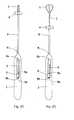
- FIGS 8A and 8Billustrate an intrauterine system and its positioning on the inserter according to an embodiment of the invention.
- the intrauterine systemhas a frame 1 a and a therapeutic component 1b and it is positioned in the plunger or in an extension of the plunger 2.
- the intrauterine systemis connected to the inserter via one connection part 19.
- the first end of the plunger 2comprises one connection slot 20 for receiving the connection part 19.
- the therapeutic componentis essentially completely and the frame essentially only partly positioned in a frame slot 21.
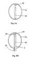
- Figures 8C and 8Dillustrate another intrauterine system and its positioning on the inserter according to an embodiment of the invention, which has the same parts 1a, 1b, 2, 19 and 20 as in Figures 8A and 8B .
- the therapeutic componentis essentially completely positioned inside the plunger and the frame is essentially completely outside the plunger.
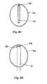
- Figures 9A and 9Billustrate some details of Figure 8B , namely the first end of the plunger 2 and the connection of the intrauterine system on the plunger.
Landscapes
- Health & Medical Sciences (AREA)
- Reproductive Health (AREA)
- Engineering & Computer Science (AREA)
- Biomedical Technology (AREA)
- Heart & Thoracic Surgery (AREA)
- Vascular Medicine (AREA)
- Life Sciences & Earth Sciences (AREA)
- Animal Behavior & Ethology (AREA)
- General Health & Medical Sciences (AREA)
- Public Health (AREA)
- Veterinary Medicine (AREA)
- Orthopedics, Nursing, And Contraception (AREA)
- Ropes Or Cables (AREA)
- Materials For Medical Uses (AREA)
- Coating Apparatus (AREA)
Description
- The present invention is related to an inserter for positioning an intrauterine device or an intrauterine system in the uterus. Document
EP-A-0798 999 represents the closest prior art. - Various types of inserters have been developed for the positioning of mechanical and copper wire-containing intrauterine devices (IUDs) as well as of intrauterine systems having a drug containing cylinder (IUSs). In the following, IUD and IUS can be used interchangeably and when one is mentioned, it is to be understood that either of them can be used.
- Most common inserters are constructed for introducing the device into the uterus in a contracted state. These inserters usually comprise an insertion tube having a relatively narrow diameter and a rounded, blunt end which will pass through the cervical canal easily and will not damage or injure the fundus upon contact therewith, and a plunger inside the insertion tube. Prior to insertion the device, whether an IUD or an IUS, is usually retracted into the insertion tube either by means of string(s) attached to the device and intended for the removal of the device from the uterus, or by pushing the device into the insertion tube by a plunger with inserters having a special window to adapt the device in the expanded shape (see for
example GB 1 403 393 - Simple rod-shaped inserters have been suggested for inserting relatively small or sufficiently flexible intrauterine devices in their original, expanded shape by using simple push-in technique. With these inserters the correct positioning and a secure attachment of an IUS or IUD on the inserter as well as a proper handling of the removal strings may be difficult. Therefore there is still need for an improved inserter.
- European patent application
EP1 691 740 relates to an inserter, with which the correct positioning and directional stiffness of the device in the inserter prior to and during insertion can be ensured, for instance, by shaping the forward end of the plunger such that the IUS assumes a specified constant configuration when drawn into the insertion tube. The IUS thus will not be twisted during insertion. - European patent
EP 798 999 - The inserters described in these documents overcome many of the problems encountered with the conventional inserters, but the string(s) still need to be handled and manually locked. Further, the inserters are designed primarily for the insertion of the conventional devices which are to be inserted in a compressed configuration. Therefore there is still need for an improved inserter, which can be used to insert in original expanded configuration intrauterine devices and systems having frames of various shapes.
- An object of the invention is to provide a simple, easy to use inserter for the positioning of an intrauterine system in the uterus by solving at least partially at least some of the problems mentioned above. An object of the invention is particularly to provide an inserter having an improved system for securing the simple and correct positioning of the intrauterine system in the uterus.
- A typical inserter for an intrauterine system according to the present invention, comprises
- a handle having a longitudinal opening at its first end, said opening having a longitudinal axis parallel to the longitudinal axis of the inserter, a first end and a second end,
- a movable slider arranged in said longitudinal opening and having a first end and a second end,
- a plunger attached to the handle and having a longitudinal axis,
- an insertion tube having a first end, a second end and a longitudinal axis essentially parallel to the longitudinal axis of the plunger, the insertion tube being, along said longitudinal axis, movably arranged around the plunger,
- a flange arranged on the insertion tube at its first end.
- The inserter is characterized in that it further comprises
- - means for locking the slider into a position showing the correct insertion depth for the intrauterine system, said means being adjustable with respect to the opening of the handle.
Figure 1 illustrates a general overview of an inserter according to an embodiment of the invention.Figures 2A, 2B ,2C and 2D illustrate an operating principle of an inserter according to an embodiment of the invention.Figures 3A and 3B illustrate a locking means according to an embodiment of the invention.Figures 4A and 4B illustrate a locking means according to another embodiment of the invention.Figures 5A and 5B illustrate a locking means according to yet another embodiment of the invention.Figures 6A and 6B illustrate a locking means according to a further embodiment of the invention.Figures 7A and 7B illustrate a locking means according to still a further embodiment of the invention.Figures 8A and 8B illustrate an intrauterine system and its positioning on the inserter according to an embodiment of the invention.Figures 8C and 8D illustrate another intrauterine system and its positioning on the inserter according to an embodiment of the invention,Figures 9A and 9B illustrate some details ofFigure 8B .- A typical inserter for an intrauterine system according to the present invention, comprises
- a handle having a longitudinal opening at its first end, said opening having a longitudinal axis parallel to the longitudinal axis of the inserter, a first end and a second end,
- a movable slider arranged in said longitudinal opening and having a first end and a second end,
- a plunger attached to the handle and having a longitudinal axis,
- an insertion tube having a first end, a second end and a longitudinal axis essentially parallel to the longitudinal axis of the plunger, the insertion tube being, along said longitudinal axis, movably arranged around the plunger,
- a flange arranged on the insertion tube at its first end.
- The inserter is characterized in that it further comprises
- means for locking the slider into a position showing the correct insertion depth for the intrauterine system, said means being adjustable with respect to the opening of the handle.
- The invention therefore provides an easy to use inserter, by which only few simple steps are needed to prepare for the insertion and to securely install and position an intrauterine system into the uterus.
- The longitudinal opening on the handle can have be also quite narrow and does not need to be symmetrically positioned on the handle and with respect to the longitudinal axis
- The inserter comprises a flange arranged on the insertion tube at its first end. The aim of this flange is to keep the intrauterine system in a correct position and to protect it prior to insertion. The flange also functions as part of the means regulating the movement of the insertion tube.
- The inserter may further comprise means for holding and guiding the strings during the insertion so that no manual handling of said strings will be needed. The inserter may also comprise locking means for reversibly locking the strings to immobilize the intrauterine system in relation to the plunger, said locking means being controllable by the slider and/or by the insertion tube.
- The inserter according to the invention is suitable for the positioning of intrauterine devices and intrauterine systems having different sizes and shapes. The inserter is especially suitable for installing intrauterine devices having a flexible frame with continuous curved shape, for example annular, circular, oval, spiral, toroidal, triangular, shield-like, almond-like, diamond-like, elliptical or polygonal shape.
- In the present description and claims, by first ends are typically meant the ends that are closer to the uterus during the insertion of the intrauterine system. Second ends are the ends opposite to the first ends. Moreover, the terms IUS or IUD and removal strings are used when describing the preferred embodiment of the present invention, but these are not to be construed as limiting the claims.
- A part of the handle comprises an opening having a first end and a second end and running in the longitudinal direction of the plunger. The handle also preferably has at its first end a channel in which the insertion tube can slide in the longitudinal direction.
- The handle can have many shapes and is designed for easy handling of the inserter even by using only one hand. The plunger attached to the handle is advantageously hollow or has a groove or bore running in the axial direction thus allowing the string(s) to slide freely in it, without any risk of them getting jammed between the plunger and the insertion tube. To enable the optimal and secure positioning of the intrauterine system in the inserter the forward end of said plunger is shaped to the form of a a slot or an extension to adapt the reservoir of the intrauterine system. Thus the IUS will not drop or be twisted during insertion procedure and assumes a specified constant configuration when released.
- The forward part (part directed towards the uterus) of the inserter is preferably made of a flexible material to avoid perforation of the uterus, and can be straight or curved so as to conform to the anatomy of the uterus. The first end of the insertion tube comprises a flange and both are made of a relatively flexible material, but are preferably stiffer than the plunger.
- The slider mechanism is preferably inside the handle and comprises at least one elongated element, which can be moved in the longitudinal direction of the insertion tube. According to an embodiment of the invention the slider comprises a means to move the slider, which preferably is a part of the slider. According to another embodiment of the invention the slider comprises at least two elements, preferably parallel, which are combined on at least one point by a transversal member. The transversal member may form means, for example a knob or switch, by which the slider can be moved. The handle can comprise one or more means to adapt the slider elements and to facilitate the movement of the slider, for example a support, a shoulder, a holder, a saddle, a groove or a slot. The slider may also comprise at least one structural element, for example an extension, which is capable to generate the necessary operation of the possible locking means to keep the strings immobilized during storage or during preparatory steps before insertion and/or to release the string(s) when the slider is moved to the backward position.
- To ensure the correct positioning of the intrauterine system in the uterus, the slider is adjusted to correspond to the depth at which intrauterine system will be inserted, said depth being beforehand determined by using a sound or a probe. The slider comprising said means for locking it, which means are adjustable with respect to the opening of the handle can be for example a self-locking button slider and movable in a stepwise way controlled for example by an indentation, a cogwheel or a rack and pinion mechanism positioned inside the handle. The outer side of the handle has clear depth markings to facilitate the adjustment of the slider.
- The slider and/or the insertion tube may additionally comprise at least one structural element, for example an extension, which is capable to generate the necessary operation of the locking means to keep the strings immobilized during storage or during preparatory steps before insertion or to release the string(s) when the slider is moved to the backward position.
- According to an embodiment of the invention relating to the kit comprising also an intrauterine system, a therapeutic component of the intrauterine system is connected to the frame in at least one point. Moreover, the intrauterine system can be connected to the inserter for example via at least one connection part. The connection part is preferably designed such that it enhances the retention of the device on the inserter prior and during the insertion of the device.
- The connection part can be for example a hollow knob, adapted to receive a pin, one of these parts being arranged on the intrauterine system and the other on the inserter. Another option is to use a traditional ball joint. A person skilled in the art is readily able to find a suitable solution for this connection part.
- Also in view of this, and according to an embodiment of the invention, the first end of the plunger comprises at least one connection slot for receiving the connection part of the intrauterine system. The first end of the plunger may also comprise two diagonally symmetrical connection slots for receiving the connection part of the intrauterine system. It is naturally possible that there are more than two connection slots, such as three, four, five or six slots. The connection part then preferably comprises suitable parts fitting to these connections slots.
- According to another embodiment of the invention, the first end of the plunger comprises at least one frame slot for receiving the frame of the intrauterine system. The first end of the plunger may also comprise two diagonally symmetrical frame slots for receiving the frame of the intrauterine system. The number of frame slots can also be higher, such as three, four, five or six. The frame slots can be parallel to the longitudinal axis of the plunger or non-parallel to it. The frame slots can for example be straight or slightly curved with respect to the outer surface of the plunger, in order for allowing the frame to be released. The frame slots are preferably narrow enough to prevent the therapeutic component from slipping out and long enough to allow the movement of the therapeutic component and the stretching/compression of the frame during the insertion step. The plunger or at least the first end of the plunger is large enough for containing the therapeutic component. The frame slot(s) together with connection parts and the flange assure that the intrauterine system will be securely fitted and in the correct configuration during the insertion.
- According to a further embodiment of the invention, the first end of the insertion tube comprises at least one frame slot for receiving the frame of the intrauterine system. The first end of the insertion tube may also comprise two diagonally symmetrical frame slots for receiving the frame of the intrauterine system. The number of frame slots can also be higher, such as three, four, five or six. The frame slots can be parallel to the longitudinal axis of the insertion tube or non-parallel to it. The frame slots can for example be straight or slightly curved with respect to the outer surface of the insertion tube, in order for allowing the frame to be released. The frame slots are preferably narrow enough to prevent the therapeutic component from slipping out and long enough to allow the movement of the therapeutic component and the stretching/compression of the frame.
- The inserter according to the present invention may also comprise locking means for reversibly locking the intrauterine system in relation to the plunger, said locking means being controllable by the slider and/or the insertion tube. This means that the locking means can also be controlled by a part of the slider and/or of the insertion tube, such as an extension of either or both of them. The locking means is any arrangement which, induced by the movement of the slider, of the means to move the slider or of the insertion tube, can immobilize the removal string(s) to held IUS in stable position and again unlock the string(s) after insertion to release the IUS. Particularly, the invention relates to a locking means which comprises an object capable of reversibly preventing the movement of the string(s) by at least partly moving or pivoting from the original position, for example rotating around a shaft or an axle, and vertically or horizontally attached to the handle. The object may have several shapes and may be for example round or rod-shaped, wedge, polygonal or rectangular with rounded or sharp corners. The surface of the object preferably comprises one or more extensions having variable size and shape, for example a knob, a rib or a switch.
- When the slider mechanism is pressed down and moved to adjust the correct insertion depth a part or an extension of the slider is pressed against at least one extension of the object thus changing its orientation enough relative to the original position to cause release of the string(s). As soon as the slider is released, the strings will lock again.
- Preferably the object has a slot or pinhole through which the string(s) run. The locking means may also comprise at least one counterpart against which the string(s) are pressed by the object and thus reversibly immobilized in the locking position. The counterpart has a suitable shape adapted to fit at least some part of the surface of the object. An extension, or extensions of the object can be used to keep the object and the counterpart in a fixed configuration until the IUS is released. The counterpart preferably has a suitable design to keep the string(s) in proper direction, for example a slot or pinhole through which the string(s) run. Further, the object and said at least one counterpart have preferably a suitable length and diameter to fit inside the handle.
- As an alternative or in addition to the locking means, the outer surface of the insertion tube or the handle can have means to hold the strings until the intrauterine system has been inserted.
- According to one embodiment of the invention, the locking means thus comprises
- a main part,
- a first extension of the main part having an abutment surface,
- a counterpart adapted to form a blocking together with the main part,
- According to another embodiment of the invention the main part comprises an opening or a slot in a diagonal direction through essentially the whole diameter of the main part, adapted to receive at least one removal string of the intrauterine system.
- According to yet another embodiment of the invention, the locking means comprises
- a main part,
- a first extension of the main part having an abutment surface,
- a second extension of the main part having a wedge-like shape,
- a counterpart adapted to form a blocking together with the main part,
- According to one embodiment of the invention, the main part has essentially the shape of a cylinder, or it is of triangular shape, or of any other suitable shape.
- According to one embodiment of the invention the insertion tube comprises an extension adapted to abut on the abutment surface of the first extension of the main part of the locking means.
- According to one other embodiment of the invention the locking means comprises a main part comprising a first extension and a second extension arranged, in their initial position, to be essentially in contact with each other to from a blocking, wherein a part of the slider, the insertion tube or a part of the insertion tube is arranged to protrude into the main part of the locking means so as to separate the first and second extensions from each other.
- According to yet one other embodiment of the invention the locking means comprises
- a first locking part and a second locking part movably mounted on the inserter and arranged, in their initial position, to be essentially in contact with each other to form a blocking, and
- a first protrusion and a second protrusion arranged on the inner surface of the outer insertion tube,
- The locking means could also be welding, gluing, cutting, knot or adhesion. The strings could thus be for example attached to the body of the inserter by welding (for example by heating), gluing with glue or attaching with an adhesive agent (such as sticker). The insertion tube would then release the attachment when contacting the slider. Other options could be a knot or other mechanical hindrance, when the slot provided for the strings is larger in the releasing position. The insertion tube could also comprise a blade that cuts the strings away from the inserter.
- It is obvious to a person skilled in the art that, in accordance with the above description, the locking means can be of any other kind than those specifically listed above as well as a combination thereof.
- During the preparatory steps the string(s) are hold tightly or locked but they are released automatically, when the slider is moved for example to adjust the insertion depth or when the second end of the insertion tube meets the slider or when the inserter is drawn out after insertion in order to release the IUS. As compared to previous inserters there is no need to manually handle the removal strings during the preparatory steps and during insertion, which increases security and hygiene and eliminates the possibility of user-made mistakes. Moreover, during the insertion the plunger and the medical device are protected by the insertion tube up to the cervix, which also increases hygiene. The invention further relates to a kit comprising an intrauterine system and an inserter according to the present invention. The intrauterine system can be any intrauterine system known in the art. Any details and embodiments listed above naturally apply mutatis mutandis to the kit according to the invention.
- A method for positioning an intrauterine system in a uterus of a patient, wherein the method uses an inserter according to the present invention is also disclosed. The method comprises the steps of
- sounding the depth of the uterus to obtain the correct positioning depth,
- moving the slider mechanism towards the second end of the opening until its position corresponds to said positioning depth, as shown by the depth markings of the handle,
- introducing the inserter into the uterus of the patient until the flange on the insertion tube abuts the cervical opening,
- introducing the plunger with the intrauterine system further into the uterus until the insertion tube meets the slider while moving backwards away from the uterus, which shows that the intrauterine system is in its correct location,
- removing the inserter from the uterus of the patient.
- An example of the method for positioning the intrauterine system is given hereafter. To insert the IUS only few steps are needed. To prepare for the insertion the sterile package is carefully opened. The IUS is in a correct configuration relative to the inserter and there is no need to align the intrauterine system or for example to rearrange or correct the frame. The IUS is positioned at the forward end of the plunger with the reservoir of the intrauterine system protected by the extension of the plunger and the frame locating outside the plunger in the expanded configuration, secured and protected by the flange. The removal string(s) attached to the intrauterine system are preferably immobilized by the locking means, by the means on the surface of the insertion tube, or by both, to keep the IUS at a steady and correct position until it is released in the uterus. The removal strings do however not necessarily need to be immobilized.
- Prior to the insertion procedure the depth of the uterus is measured by sounding. The slider mechanism or the means to move the slider is moved to correspond to the correct sounding depth. In the simplest form the slider is equipped with a self-locking press down and slide back button to adjust the correct sounding depth.
- Then, the handle is hold tightly and the inserter is introduced into the uterus until the flange touches the cervical opening. At this point the insertion tube starts moving backwards and the flexible plunger with the intrauterine system will go forwards into the uterus. The insertion is continued until the insertion tube meets the slider, when also the removal string(s), if locked, are released by the locking means or by the means on the insertion tube. At this point IUS is in the correct location, as determined beforehand by using a sound as described above.
- The inserter thus allows easy and secure positioning of an IUS. The use of the slider mechanism is straightforward and the locking means to hold the string(s) and the IUS immobile long enough as well as the predetermined distances the insertion tubes can be moved in each step guarantee an accurate positioning of the IUS during insertion and its accurate release.
- In the following description, the term slider and the corresponding reference number are used to designate both the slider itself and the means to move the slider attached to the slider. The term slider is used for convenience of reading.
Figure 1 illustrates a general overview of an inserter according to the invention. The inserter comprises ahandle 3, aplunger 2 attached to the handle, a slider having means to move theslider 5, aninsertion tube 6 around the plunger, an IUS and the string or strings (not shown here) for the removal of the IUS, means for reversibly locking the string(s) (not shown) in such a way that the IUS remains immobile in relation to the plunger during the necessary steps prior to and during insertion, and again for releasing the string(s) and the IUS after it has been inserted, anopening 8, achannel 9 in which the insertion tube slides in the longitudinal direction, anddepth markings 19 on the handle which are used to adjust the slider to correspond the depth of the uterus.- In this case the forward part of the
handle 3 forms anopening 8, having thefirst end 8a and thesecond end 8b, which opening runs in the direction of theplunger 2 and has at the first end achannel 9 in which theinsertion tube 6 slides in the longitudinal direction. The front surface of the means to move theslider 5a is set on the depth marking corresponding the depth od the uterus, i.e. the insertion depth, as determined before hand by using a sound or a probe. Figs. 2A , 2B ,2C and 2D illustrate an operating principle of the inserter.Fig. 2A shows an inserter and in this case an almond-shapedIUS 1 in a configuration as they are in the sterilized package. The IUS is placed in the front end (entry into the uterus) of the inserter so that the elongate member of the intrauterine system or the elongated member with a drug containing reservoir is inside the head of the plunger and the frame of the intrauterine system is in the expanded configuration and partly covered by theflange 4. The means to move theslider 5 is on the basic position. The removal string(s) are inside the inserter, tightened and locked by the locking means (not shown in the Figure) or outside under the insertion tube hold by suitable means or extensions.Figure 2B illustrates the first step of insertion procedure. After the insertion depth has been determined by sounding, the slider is moved backwards untilsurface 5a is on a correct depth marking of thehandle 3.Figure 2C illustrates the procedure to insert the IUS. The intrauterine system in the configuration according toFigure 2B is gently introduced into the uterus until the flange abuts the cervical opening. The frame of the IUS will compress against the head of the plunger.Figure 2D illustrates the final step of insertion procedure. Insertion is continued from the step ofFigure 2C . The flange pressed against the cervical opening will cause the insertion tube to move backwards, and only the plunger with the intrauterine system will move towards the uterus. The insertion tube will move until the rear end of the tube meets the slider and at this point the intrauterine system is correctly positioned in the uterus. The inserter is retracted out of the uterus. The strings and the intrauterine system are automatically released when the insertion tube meets the slider or when the inserter is drawn out. The distance the insertion tube can move has been selected to indicate clearly the moment at which the IUS has completely been positioned.Figures 3A and 3B illustrate a locking means according to an embodiment of the invention. The locking means are arranged preferably at the inside of thehandle 3, on any of the inside surfaces of the handle. The locking means are used to immobilise and release the string(s) of the IUS.Figure 3A illustrates a locking means according to an embodiment of the invention comprising amain part 10 having essentially the shape of a cylinder and comprising anopening 12 there through in a diagonal direction. The string(s) 7 of the IUS pass through theopening 12. Themain part 10 is rotatably mounted on the handle, on a shaft or an axle (not shown). The locking means also comprises acounterpart 11, such that in the locking position the string(s) are immobilized between the counterpart and the main part. The counterpart thus has a suitable shape adapted to fit to a part of the surface of the main part. When the slider is moving backwards, at a suitable point a part or an extension of the slider is pressed against theextension 10a of themain part 10 thus turning it enough to release the string(s), as shown inFigure 3B .Figures 4A and 4B illustrate a locking means according to another embodiment of the invention.Figure 4A illustrates an object similar to the one presented inFigure 3A , but having a different construction of theextension 10a.Figures 5A and 5B illustrate a locking means according to yet another embodiment of the invention. This is a side view of a cylindrically shaped locking means, having amain part 13 which comprises twoextensions axle 14 and is preferably attached to a shorter side of the inner surface of the handle. The locking means also comprises acounterpart 15 such that the string(s) 7 are immobilised between thecounterpart 15 and theextension 13b. Thecounterpart 15 has a suitable shape adapted to fit to a part of the surface of theextension 13b. When the slider is moving backwards, at a suitable point a part or an extension of the slider is pressed against theextension 13a thus turning it enough to release the string(s), as shown inFigure 5B . In this case the handle can also comprise a groove in which the string(s) run (not shown).Figures 6A and 6B illustrate a locking means according to an embodiment of the invention. The locking means 16 comprises twoextensions Figure 6A . When theslider 5 and theinsertion tube 6 move backwards the slider and/or the insertion tube protrudes into the locking means at least partly to expand the means enough to separate the extensions and to release the strings, as shown inFigure 6B .Figures 7A and 7B illustrate a locking means according to a further embodiment of the invention. The locking means comprises twoparts Figure 7A , said parts being able to move or turn from the original position. Theslider 5 has twoextensions slider 5 and theinsertion tube 6 move backwards the slider extensions turn thelocking parts Figure 7B .Figures 8A and 8B illustrate an intrauterine system and its positioning on the inserter according to an embodiment of the invention. The intrauterine system has aframe 1 a and atherapeutic component 1b and it is positioned in the plunger or in an extension of theplunger 2. The intrauterine system is connected to the inserter via oneconnection part 19. The first end of theplunger 2 comprises oneconnection slot 20 for receiving theconnection part 19. The therapeutic component is essentially completely and the frame essentially only partly positioned in aframe slot 21.Figures 8C and 8D illustrate another intrauterine system and its positioning on the inserter according to an embodiment of the invention, which has thesame parts Figures 8A and 8B . In this embodiment, the therapeutic component is essentially completely positioned inside the plunger and the frame is essentially completely outside the plunger.Figures 9A and 9B illustrate some details ofFigure 8B , namely the first end of theplunger 2 and the connection of the intrauterine system on the plunger.
Claims (5)
- An inserter for an intrauterine system comprising- a handle (3) having a longitudinal opening (8) at its first end, said opening (8) having a longitudinal axis parallel to the longitudinal axis of the inserter, a first end (8a) and a second end (8b),- a movable slider (5) arranged in said longitudinal opening (8) and having a first end (5a) and a second end (5b),- a plunger (2) attached to the handle (3) and having a longitudinal axis,- an insertion tube (6)having a first end, a second end and a longitudinal axis essentially parallel to the longitudinal axis of the plunger (2), the insertion tube being, along said longitudinal axis, movably arranged around the plunger (2), and comprising a flange,
characterized in that- the flange (4) is arranged on the insertion tube (6) at its first end, andin that the inserter further comprises- means for locking the slider (5) into a position showing the correct insertion depth for the intrauterine system, said means being adjustable with respect to the opening (8) of the handle. - An inserter according to claim 1,characterised in that the flange (4) is arranged to at least partially protect the intrauterine system before its insertion.
- An inserter according to claim 1 or 2,characterised in that the the means for locking the slider (5) comprises a self-locking button movable in a stepwise way.
- An inserter according to any of the preceding claims,characterised in that it further comprises means for holding and guiding the removal strings of the intrauterine system during its insertion.
- A kit comprising an intrauterine system and an inserter according to any of the claims 1-4.
Priority Applications (1)
| Application Number | Priority Date | Filing Date | Title |
|---|---|---|---|
| PL09736243TPL2352469T3 (en) | 2008-09-17 | 2009-09-11 | An inserter |
Applications Claiming Priority (2)
| Application Number | Priority Date | Filing Date | Title |
|---|---|---|---|
| FI20080524AFI20080524A0 (en) | 2008-09-17 | 2008-09-17 | An inserter |
| PCT/FI2009/050733WO2010031899A1 (en) | 2008-09-17 | 2009-09-11 | An inserter |
Publications (2)
| Publication Number | Publication Date |
|---|---|
| EP2352469A1 EP2352469A1 (en) | 2011-08-10 |
| EP2352469B1true EP2352469B1 (en) | 2012-11-14 |
Family
ID=39852187
Family Applications (1)
| Application Number | Title | Priority Date | Filing Date |
|---|---|---|---|
| EP09736243AActiveEP2352469B1 (en) | 2008-09-17 | 2009-09-11 | An inserter |
Country Status (13)
| Country | Link |
|---|---|
| US (5) | US20110172593A1 (en) |
| EP (1) | EP2352469B1 (en) |
| JP (1) | JP5571670B2 (en) |
| KR (1) | KR101604508B1 (en) |
| CN (1) | CN102159161B (en) |
| CA (1) | CA2735933C (en) |
| DK (1) | DK2352469T3 (en) |
| ES (1) | ES2399381T3 (en) |
| FI (1) | FI20080524A0 (en) |
| HR (1) | HRP20120970T1 (en) |
| PL (1) | PL2352469T3 (en) |
| PT (1) | PT2352469E (en) |
| WO (1) | WO2010031899A1 (en) |
Families Citing this family (39)
| Publication number | Priority date | Publication date | Assignee | Title |
|---|---|---|---|---|
| US11992431B2 (en) | 2008-09-17 | 2024-05-28 | Bayer Oy | Inserter |
| FI20080524A0 (en) | 2008-09-17 | 2008-09-17 | Bayer Schering Pharma Oy | An inserter |
| ES2424984T5 (en) | 2008-09-17 | 2017-02-16 | Bayer Oy | Inserter |
| FI20080523A0 (en) | 2008-09-17 | 2008-09-17 | Bayer Schering Pharma Oy | An inserter |
| FI122579B (en) | 2010-10-29 | 2012-03-30 | Bayer Oy | inserter |
| JP6068350B2 (en) | 2010-10-29 | 2017-01-25 | オディセア・ファルマ・ソシエテ・プリベ・ア・レスポンサビリテ・リミテOdyssea Pharma S.P.R.L. | Intrauterine insertion device |
| US8608738B2 (en) | 2010-12-06 | 2013-12-17 | Soulor Surgical, Inc. | Apparatus for treating a portion of a reproductive system and related methods of use |
| US9237925B2 (en) | 2011-04-22 | 2016-01-19 | Ablative Solutions, Inc. | Expandable catheter system for peri-ostial injection and muscle and nerve fiber ablation |
| US8663190B2 (en) | 2011-04-22 | 2014-03-04 | Ablative Solutions, Inc. | Expandable catheter system for peri-ostial injection and muscle and nerve fiber ablation |
| US10028858B2 (en)* | 2011-07-11 | 2018-07-24 | Medicines360 | Intrauterine systems, IUD insertion devices, and related methods and kits therefor |
| US20130053792A1 (en) | 2011-08-24 | 2013-02-28 | Ablative Solutions, Inc. | Expandable catheter system for vessel wall injection and muscle and nerve fiber ablation |
| US9056185B2 (en) | 2011-08-24 | 2015-06-16 | Ablative Solutions, Inc. | Expandable catheter system for fluid injection into and deep to the wall of a blood vessel |
| US9265652B2 (en) | 2012-08-14 | 2016-02-23 | Contramed, Llc | Intrauterine contraceptive device |
| US9089418B2 (en) | 2012-08-14 | 2015-07-28 | Contramed, Llc | Intrauterine contraceptive device |
| PT106603A (en)* | 2012-10-26 | 2014-04-28 | Beyondevices Lda | DISTRIBUTION MECHANISM FOR THE ADMINISTRATION OF PHARMACEUTICAL FORMS IN CORPORATE FORMS AND APPLICATOR UNDERSTANDING THE SAME |
| US10945787B2 (en) | 2012-10-29 | 2021-03-16 | Ablative Solutions, Inc. | Peri-vascular tissue ablation catheters |
| US10881458B2 (en) | 2012-10-29 | 2021-01-05 | Ablative Solutions, Inc. | Peri-vascular tissue ablation catheters |
| US9526827B2 (en) | 2012-10-29 | 2016-12-27 | Ablative Solutions, Inc. | Peri-vascular tissue ablation catheter with support structures |
| US10736656B2 (en) | 2012-10-29 | 2020-08-11 | Ablative Solutions | Method for painless renal denervation using a peri-vascular tissue ablation catheter with support structures |
| US9301795B2 (en) | 2012-10-29 | 2016-04-05 | Ablative Solutions, Inc. | Transvascular catheter for extravascular delivery |
| KR101287554B1 (en)* | 2013-03-19 | 2013-07-19 | 김재명 | Uterine elevator |
| CN105579000A (en)* | 2013-09-11 | 2016-05-11 | 拜耳股份有限公司 | training inserter |
| US10918516B2 (en) | 2013-10-14 | 2021-02-16 | Sebela Vlc Limited | Intrauterine device with controlled copper ion elution |
| US10188546B2 (en) | 2013-10-14 | 2019-01-29 | Sebela Vlc Limited | Intrauterine device with controlled copper ion elution |
| US9180040B2 (en) | 2013-10-18 | 2015-11-10 | Contramed, Llc | Intrauterine device with retrieval thread |
| US10517666B2 (en) | 2013-10-25 | 2019-12-31 | Ablative Solutions, Inc. | Apparatus for effective ablation and nerve sensing associated with denervation |
| US9931046B2 (en) | 2013-10-25 | 2018-04-03 | Ablative Solutions, Inc. | Intravascular catheter with peri-vascular nerve activity sensors |
| US9949652B2 (en) | 2013-10-25 | 2018-04-24 | Ablative Solutions, Inc. | Apparatus for effective ablation and nerve sensing associated with denervation |
| CN105055072B (en)* | 2015-07-09 | 2017-07-14 | 胡友斌 | A kind of contraceptive embedded device and its operating method |
| DE102016107886A1 (en)* | 2016-04-28 | 2017-11-02 | Hamid Huschmand Nia | Intrauterine device and method for introducing the intrauterine device |
| JOP20190071A1 (en)* | 2016-10-06 | 2019-04-04 | Bayer Oy | An arrangement for an intrauterine system and its inserter |
| US11571328B2 (en) | 2018-04-09 | 2023-02-07 | Medicines360 | IUD insertion devices |
| US10849685B2 (en) | 2018-07-18 | 2020-12-01 | Ablative Solutions, Inc. | Peri-vascular tissue access catheter with locking handle |
| CN109009646B (en)* | 2018-08-07 | 2020-05-12 | 浙江大学 | Uterine cavity barrier device |
| CA3160029A1 (en) | 2019-10-09 | 2021-04-15 | Steven R. Bacich | Apparatus and method for everting catheter for iud delivery and placement in the uterine cavity |
| US11571329B2 (en) | 2019-11-21 | 2023-02-07 | Coopersurgical, Inc. | Packaging systems for implantable devices and related methods |
| FR3128368B1 (en) | 2021-10-21 | 2025-07-11 | Patrick Choay Sas | Inserter for inserting an intrauterine device |
| USD1070085S1 (en)* | 2022-03-17 | 2025-04-08 | Pregna International Limited | Intra-uterine inserter |
| FR3138299B1 (en) | 2022-07-26 | 2025-04-18 | Patrick Choay Sas | Inserter for inserting an intrauterine device |
Family Cites Families (85)
| Publication number | Priority date | Publication date | Assignee | Title |
|---|---|---|---|---|
| BE642378A (en) | 1963-01-10 | |||
| US3678927A (en) | 1968-03-18 | 1972-07-25 | Samuel Soichet | Intra uterine device and injector thereof |
| US3533406A (en) | 1968-09-18 | 1970-10-13 | Population Council Inc | Intrauterine contraceptive device |
| US3896819A (en) | 1969-04-01 | 1975-07-29 | Alejandro Zaffaroni | IUD having a replenishing drug reservoir |
| US3656483A (en) | 1970-01-15 | 1972-04-18 | Biolog Concepts Inc | Intrauterine medicator |
| US3783861A (en)* | 1971-06-11 | 1974-01-08 | Searle & Co | Inserter for intrauterine devices |
| BE791734A (en)* | 1971-10-07 | 1973-03-16 | Robins Co Inc A H | UNIVERSAL DEVICE FOR INSERTION OF INTRA-UTERINE DEVICES |
| BE791739A (en) | 1971-10-07 | 1973-03-16 | Robins Co Inc A H | INTRA-UTERINE TREATMENT DEVICES |
| NL173707C (en) | 1974-02-14 | 1984-03-01 | Multilan Sa | COMPOSITION OF INTRA-UTERINE ANTI-CONCEPTION DEVICE AND ASSOCIATED INSERTS CASE. |
| US3918444A (en) | 1974-03-27 | 1975-11-11 | Alza Corp | Apparatus for inserting an intrauterine device |
| US3902483A (en) | 1974-08-21 | 1975-09-02 | Alza Corp | Intrauterine device with locator means for indicating uterine position of device |
| FR2317945A1 (en) | 1975-07-16 | 1977-02-11 | Searle Sa Laboratoires | INTRA-UTERINE INSERTER |
| NL7802043A (en)* | 1977-03-28 | 1978-10-02 | Ortho Pharma Corp | INSTRUMENT FOR THE INSERTION OF AN INTRA-UTERINE ANTI-CONCEPTION AGENT AND A METHOD FOR THE INSERTION OF AN INTRA-UTERINE ANTI-CONCEPTION AGENT. |
| ES239677Y (en) | 1978-11-23 | 1979-06-16 | Sopena Quesada Angel | INTRAUTERINE SPERM |
| US4341728A (en) | 1979-12-20 | 1982-07-27 | The Population Council, Inc. | Method for making an IUD with shrinking of a medicated attachment onto a support |
| US4413985A (en) | 1981-09-02 | 1983-11-08 | The United States Of America As Represented By The Dept. Of Health & Human Services | Hydrocephalic antenatal vent for intrauterine treatment (HAVIT) |
| US4805628A (en) | 1982-12-06 | 1989-02-21 | Indianapolis Center For Advanced Research, Inc. | Ultrasound contrast media for medically implantable and insertable devices |
| US4578075A (en) | 1982-12-20 | 1986-03-25 | Alza Corporation | Delivery system housing a plurality of delivery devices |
| US4562835A (en) | 1984-01-23 | 1986-01-07 | Ortho Pharmaceutical (Canada) Ltd. | Streamlined T-shaped intrauterine device |
| NZ207341A (en) | 1984-03-01 | 1988-02-29 | Harvey Alex Ind Ltd | Device containing chemical impregnants for insertion into a body cavity of an animal |
| US4578076A (en) | 1984-03-20 | 1986-03-25 | The Population Council, Inc. | Medicated intracervical and intrauterine devices |
| IN161985B (en)* | 1984-03-29 | 1988-03-12 | Wildemeersch Dirk | |
| DE3434207C1 (en) | 1984-09-18 | 1985-11-14 | Karl-Heinz Dr. 8703 Ochsenfurt Lurz | Variable intrauterine device and contraceptive device |
| IE57545B1 (en) | 1984-12-21 | 1992-10-21 | Akzo Nv | Assembly of intra-uterine contraceptive device and inserter |
| SU1377063A1 (en) | 1985-12-10 | 1988-02-28 | Казанский государственный медицинский институт им.С.В.Курашова | Instrument for removing intrauterine contraceptives |
| NL8601570A (en) | 1986-06-17 | 1988-01-18 | Futura Nova Bv | Intra-uterine contraceptive device has rod secured to ring - having max. length equal to ring dia. and rod may carry e.g. copper coil or spermicidal or therapeutic agent |
| DE3717538A1 (en) | 1987-05-25 | 1988-12-08 | Hermann Keck | RECEPTION PREVENTIVE DEVICE |
| DE8712168U1 (en) | 1987-09-08 | 1987-10-22 | Naučno-proizvodstvennoe ob"edinenie Medinstrument, Kazan | Device for introducing contraceptive devices into the uterine cavity |
| FI80523C (en) | 1988-06-10 | 1990-06-11 | Limnos Oy | A sampler. |
| US5146931A (en) | 1988-08-15 | 1992-09-15 | Kurz Karl Heinz | Device to be placed in the uterus |
| US5217450A (en) | 1989-07-21 | 1993-06-08 | Carter Holt Harvey Plastic Products Group Limited | Retention devices |
| US4949732A (en) | 1989-08-24 | 1990-08-21 | Gyno Pharma Inc. | Apparatus for insertion and fixation of an intra uterine contraceptive device to the uterine fundus |
| US5224493A (en) | 1991-01-30 | 1993-07-06 | Cadco Corporation | Contraceptive intracervical device and novel nonsystemic agents for the prevention of conception and disease |
| US5370129A (en)* | 1992-08-28 | 1994-12-06 | Db Inserters, Inc. | IUD inserting apparatus |
| NL9400410A (en) | 1994-03-16 | 1995-11-01 | M D Ph D Willem Arthur Adriaan | Intrauterine contraceptive. |
| WO1995028901A1 (en) | 1994-04-25 | 1995-11-02 | Akzo Nobel N.V. | Intrauterine device tray having one attachment site |
| FI97946C (en)* | 1994-12-15 | 1997-03-25 | Leiras Oy | Depositor intended for setting up a device for intrauterine use |
| AU4894196A (en) | 1995-03-09 | 1996-10-08 | Jury Vasilievich Borodin | Intrauterine contraceptive device |
| EP0803237A1 (en) | 1996-04-22 | 1997-10-29 | Enrique Horacio Turin | Intrauterine device for use in dogs and methods of insertion thereof |
| US6278057B1 (en) | 1997-05-02 | 2001-08-21 | General Science And Technology Corp. | Medical devices incorporating at least one element made from a plurality of twisted and drawn wires at least one of the wires being a nickel-titanium alloy wire |
| US6039968A (en) | 1997-06-24 | 2000-03-21 | Hoechst Marion Roussel | Intravaginal drug delivery device |
| US6293952B1 (en) | 1997-07-31 | 2001-09-25 | Circon Corporation | Medical instrument system for piercing through tissue |
| JP3342021B2 (en)* | 1997-10-17 | 2002-11-05 | サーコン コーポレーション | Medical device system that penetrates tissue |
| DE19815552C1 (en) | 1998-04-07 | 1999-09-16 | Siegfried Riek | Insertion instrument for inter uterine device |
| FI107339B (en) | 1998-06-30 | 2001-07-13 | Leiras Oy | Diaphragm or matrix intended to control the rate of penetration of drugs |
| DE29819558U1 (en)* | 1998-11-03 | 1999-02-11 | Riek, Siegfried, Dr.med., 78628 Rottweil | Handle with integrated mechanism for the defined manipulation of insertion devices for inserting an intrauterine device (TUP) into the uterine cavity |
| US6056976A (en) | 1998-11-12 | 2000-05-02 | Leiras Oy | Elastomer, its preparation and use |
| BE1012613A3 (en)* | 1999-04-16 | 2001-01-09 | Wildemeersch Dirk | PROCESS FOR RESTRAINT AND OPERATING A IUD inserter, inserter AND FOR THE APPLICATION OF THE METHOD. |
| US6763833B1 (en)* | 1999-08-23 | 2004-07-20 | Conceptus, Inc. | Insertion/deployment catheter system for intrafallopian contraception |
| US6709667B1 (en) | 1999-08-23 | 2004-03-23 | Conceptus, Inc. | Deployment actuation system for intrafallopian contraception |
| DE29919662U1 (en) | 1999-11-09 | 2000-02-03 | Riek, Siegfried, Dr.med., 78628 Rottweil | Introducer for the insertion of an intrauterine contraceptive device |
| US6213351B1 (en) | 1999-12-27 | 2001-04-10 | Courtesy Corporation | Push body valve closure |
| US20010031981A1 (en) | 2000-03-31 | 2001-10-18 | Evans Michael A. | Method and device for locating guidewire and treating chronic total occlusions |
| CN1196455C (en) | 2001-03-29 | 2005-04-13 | 华中科技大学同济医学院 | Fixed contraception device introducer |
| US8257244B2 (en) | 2001-08-01 | 2012-09-04 | Anecova Sa | Intrauterine device, method of making such a device and method for putting active elements within the uterine cavity |
| PL367961A1 (en) | 2001-08-31 | 2005-03-07 | Schering Oy | Drug delivery system |
| BE1014635A3 (en) | 2002-02-12 | 2004-02-03 | Wildemeersch Dirk | |
| EP1400258A1 (en) | 2002-09-18 | 2004-03-24 | Schering Oy | Pharmaceutical composition delivery device and its manufacturing process |
| US7294135B2 (en) | 2003-03-20 | 2007-11-13 | Medtronic Vascular, Inc | Control handle for intraluminal devices |
| GB0307082D0 (en) | 2003-03-27 | 2003-04-30 | Gyne Ideas Ltd | Drug delivery device and method |
| FI119719B (en) | 2003-11-19 | 2009-02-27 | Bayer Schering Pharma Oy | A slider |
| EP1541100A1 (en) | 2003-12-11 | 2005-06-15 | Familplan Consulting Ltd Oy | T-shaped intrauterine device and system |
| USD525705S1 (en) | 2004-01-23 | 2006-07-25 | Familplan Consulting Ltd Oy | Intrauterine device for releasing steroids |
| US7699056B2 (en) | 2004-06-10 | 2010-04-20 | Conceptus, Inc. | Medical devices and methods of making and using such devices |
| US20070056591A1 (en) | 2005-09-15 | 2007-03-15 | Mcswain Hugh | Fallopian tube occlusion devices and methods |
| NL1030795C2 (en) | 2005-12-27 | 2007-06-28 | Willem Arthur Adriaan Van Os | Intra-uterine device and sleeve for introducing it into the uterus. |
| IL173762A0 (en) | 2006-02-16 | 2006-07-05 | David Braver Dr | A device and method for the prolonged delivery of an active agent to a body cavity |
| US20080115323A1 (en) | 2006-11-17 | 2008-05-22 | Sony Ericsson Mobile Communications Ab | Spring loaded hinge mechanism |
| CN201042478Y (en) | 2007-05-17 | 2008-04-02 | 安会芹 | Intrauterine ring placing device |
| EP2057972A1 (en) | 2007-11-07 | 2009-05-13 | N.V. Organon | Intrauterine deposit |
| FI20085277A0 (en) | 2008-04-02 | 2008-04-02 | Bayer Schering Pharma Oy | Intrauterine system |
| EP2140860A1 (en) | 2008-07-03 | 2010-01-06 | Bayer Schering Pharma Oy | An improved method of contraception |
| FI20080523A0 (en) | 2008-09-17 | 2008-09-17 | Bayer Schering Pharma Oy | An inserter |
| FI20080524A0 (en)* | 2008-09-17 | 2008-09-17 | Bayer Schering Pharma Oy | An inserter |
| ES2424984T5 (en) | 2008-09-17 | 2017-02-16 | Bayer Oy | Inserter |
| ES2628552T3 (en) | 2009-01-18 | 2017-08-03 | Ocon Medical Ltd | Innovative intrauterine device |
| WO2010112095A1 (en) | 2009-04-03 | 2010-10-07 | Bio Material Systems Nv/Sa | Improvement to intrauterine copper contraceptive devices |
| US8568374B2 (en) | 2009-05-04 | 2013-10-29 | Merck Sharp & Dohme B.V. | Intrauterine system |
| USD791318S1 (en) | 2009-09-14 | 2017-07-04 | Bayer Oy | Inserter |
| US20110061659A1 (en) | 2009-09-17 | 2011-03-17 | Julian Cruzada | Minimally invasive delivery devices and methods |
| WO2011080164A1 (en) | 2009-12-21 | 2011-07-07 | Pat&Co Bvba | Improvements to frameless intrauterine devices and systems |
| US8573222B2 (en) | 2010-03-21 | 2013-11-05 | David Weintraub | Intrauterine device and inserter for the same |
| USD718435S1 (en) | 2012-05-30 | 2014-11-25 | Medicines360 | Intrauterine insertion device |
| US9180040B2 (en) | 2013-10-18 | 2015-11-10 | Contramed, Llc | Intrauterine device with retrieval thread |
| US11278445B2 (en) | 2015-07-30 | 2022-03-22 | Medicines360 | IUD loading devices and methods for inserting an IUD into an insertion device |
- 2008
- 2008-09-17FIFI20080524Apatent/FI20080524A0/ennot_activeApplication Discontinuation
- 2009
- 2009-09-11PLPL09736243Tpatent/PL2352469T3/enunknown
- 2009-09-11ESES09736243Tpatent/ES2399381T3/enactiveActive
- 2009-09-11KRKR1020117005920Apatent/KR101604508B1/ennot_activeExpired - Fee Related
- 2009-09-11PTPT97362438Tpatent/PT2352469E/enunknown
- 2009-09-11JPJP2011527361Apatent/JP5571670B2/ennot_activeExpired - Fee Related
- 2009-09-11WOPCT/FI2009/050733patent/WO2010031899A1/enactiveApplication Filing
- 2009-09-11DKDK09736243.8Tpatent/DK2352469T3/enactive
- 2009-09-11HRHRP20120970ATpatent/HRP20120970T1/enunknown
- 2009-09-11CACA2735933Apatent/CA2735933C/ennot_activeExpired - Fee Related
- 2009-09-11USUS13/119,399patent/US20110172593A1/ennot_activeAbandoned
- 2009-09-11CNCN2009801365503Apatent/CN102159161B/ennot_activeExpired - Fee Related
- 2009-09-11EPEP09736243Apatent/EP2352469B1/enactiveActive
- 2013
- 2013-04-04USUS13/857,134patent/US20130220338A1/ennot_activeAbandoned
- 2015
- 2015-01-06USUS14/590,969patent/US9707123B2/enactiveActive
- 2017
- 2017-07-11USUS15/647,104patent/US10583035B2/enactiveActive
- 2020
- 2020-03-09USUS16/813,340patent/US11432958B2/enactiveActive
Also Published As
| Publication number | Publication date |
|---|---|
| CA2735933C (en) | 2017-04-18 |
| ES2399381T3 (en) | 2013-04-01 |
| US10583035B2 (en) | 2020-03-10 |
| CN102159161B (en) | 2013-07-10 |
| EP2352469A1 (en) | 2011-08-10 |
| CN102159161A (en) | 2011-08-17 |
| FI20080524A0 (en) | 2008-09-17 |
| DK2352469T3 (en) | 2013-01-14 |
| JP2012502711A (en) | 2012-02-02 |
| CA2735933A1 (en) | 2010-03-25 |
| HK1155349A1 (en) | 2012-05-18 |
| KR101604508B1 (en) | 2016-03-17 |
| PT2352469E (en) | 2013-01-22 |
| US20130220338A1 (en) | 2013-08-29 |
| HRP20120970T1 (en) | 2012-12-31 |
| PL2352469T3 (en) | 2013-03-29 |
| US20200206021A1 (en) | 2020-07-02 |
| US20150114402A1 (en) | 2015-04-30 |
| US20180014966A1 (en) | 2018-01-18 |
| US9707123B2 (en) | 2017-07-18 |
| KR20110083599A (en) | 2011-07-20 |
| WO2010031899A1 (en) | 2010-03-25 |
| US20110172593A1 (en) | 2011-07-14 |
| JP5571670B2 (en) | 2014-08-13 |
| US11432958B2 (en) | 2022-09-06 |
Similar Documents
| Publication | Publication Date | Title |
|---|---|---|
| US11432958B2 (en) | Inserter | |
| US11911312B2 (en) | Inserter | |
| US11872155B2 (en) | Inserter | |
| US10149784B2 (en) | Inserter for an intrauterine system | |
| HK1155349B (en) | An inserter |
Legal Events
| Date | Code | Title | Description |
|---|---|---|---|
| PUAI | Public reference made under article 153(3) epc to a published international application that has entered the european phase | Free format text:ORIGINAL CODE: 0009012 | |
| 17P | Request for examination filed | Effective date:20110328 | |
| AK | Designated contracting states | Kind code of ref document:A1 Designated state(s):AT BE BG CH CY CZ DE DK EE ES FI FR GB GR HR HU IE IS IT LI LT LU LV MC MK MT NL NO PL PT RO SE SI SK SM TR | |
| AX | Request for extension of the european patent | Extension state:AL BA RS | |
| GRAP | Despatch of communication of intention to grant a patent | Free format text:ORIGINAL CODE: EPIDOSNIGR1 | |
| GRAS | Grant fee paid | Free format text:ORIGINAL CODE: EPIDOSNIGR3 | |
| GRAA | (expected) grant | Free format text:ORIGINAL CODE: 0009210 | |
| AK | Designated contracting states | Kind code of ref document:B1 Designated state(s):AT BE BG CH CY CZ DE DK EE ES FI FR GB GR HR HU IE IS IT LI LT LU LV MC MK MT NL NO PL PT RO SE SI SK SM TR | |
| AX | Request for extension of the european patent | Extension state:AL BA RS | |
| REG | Reference to a national code | Ref country code:GB Ref legal event code:FG4D | |
| REG | Reference to a national code | Ref country code:CH Ref legal event code:EP Ref country code:AT Ref legal event code:REF Ref document number:583547 Country of ref document:AT Kind code of ref document:T Effective date:20121115 | |
| REG | Reference to a national code | Ref country code:HR Ref legal event code:TUEP Ref document number:P20120970 Country of ref document:HR | |
| REG | Reference to a national code | Ref country code:CH Ref legal event code:NV Representative=s name:BOVARD AG, CH | |
| REG | Reference to a national code | Ref country code:IE Ref legal event code:FG4D | |
| REG | Reference to a national code | Ref country code:SE Ref legal event code:TRGR | |
| REG | Reference to a national code | Ref country code:HR Ref legal event code:T1PR Ref document number:P20120970 Country of ref document:HR | |
| REG | Reference to a national code | Ref country code:DE Ref legal event code:R096 Ref document number:602009011201 Country of ref document:DE Effective date:20130110 | |
| REG | Reference to a national code | Ref country code:DK Ref legal event code:T3 | |
| REG | Reference to a national code | Ref country code:PT Ref legal event code:SC4A Free format text:AVAILABILITY OF NATIONAL TRANSLATION Effective date:20121228 | |
| REG | Reference to a national code | Ref country code:NL Ref legal event code:T3 | |
| REG | Reference to a national code | Ref country code:NL Ref legal event code:T3 | |
| REG | Reference to a national code | Ref country code:PL Ref legal event code:T3 | |
| REG | Reference to a national code | Ref country code:ES Ref legal event code:FG2A Ref document number:2399381 Country of ref document:ES Kind code of ref document:T3 Effective date:20130401 | |
| REG | Reference to a national code | Ref country code:LT Ref legal event code:MG4D | |
| PG25 | Lapsed in a contracting state [announced via postgrant information from national office to epo] | Ref country code:LT Free format text:LAPSE BECAUSE OF FAILURE TO SUBMIT A TRANSLATION OF THE DESCRIPTION OR TO PAY THE FEE WITHIN THE PRESCRIBED TIME-LIMIT Effective date:20121114 Ref country code:FI Free format text:LAPSE BECAUSE OF FAILURE TO SUBMIT A TRANSLATION OF THE DESCRIPTION OR TO PAY THE FEE WITHIN THE PRESCRIBED TIME-LIMIT Effective date:20121114 Ref country code:NO Free format text:LAPSE BECAUSE OF FAILURE TO SUBMIT A TRANSLATION OF THE DESCRIPTION OR TO PAY THE FEE WITHIN THE PRESCRIBED TIME-LIMIT Effective date:20130214 | |
| PG25 | Lapsed in a contracting state [announced via postgrant information from national office to epo] | Ref country code:SI Free format text:LAPSE BECAUSE OF FAILURE TO SUBMIT A TRANSLATION OF THE DESCRIPTION OR TO PAY THE FEE WITHIN THE PRESCRIBED TIME-LIMIT Effective date:20121114 Ref country code:GR Free format text:LAPSE BECAUSE OF FAILURE TO SUBMIT A TRANSLATION OF THE DESCRIPTION OR TO PAY THE FEE WITHIN THE PRESCRIBED TIME-LIMIT Effective date:20130215 Ref country code:LV Free format text:LAPSE BECAUSE OF FAILURE TO SUBMIT A TRANSLATION OF THE DESCRIPTION OR TO PAY THE FEE WITHIN THE PRESCRIBED TIME-LIMIT Effective date:20121114 | |
| PG25 | Lapsed in a contracting state [announced via postgrant information from national office to epo] | Ref country code:CZ Free format text:LAPSE BECAUSE OF FAILURE TO SUBMIT A TRANSLATION OF THE DESCRIPTION OR TO PAY THE FEE WITHIN THE PRESCRIBED TIME-LIMIT Effective date:20121114 Ref country code:EE Free format text:LAPSE BECAUSE OF FAILURE TO SUBMIT A TRANSLATION OF THE DESCRIPTION OR TO PAY THE FEE WITHIN THE PRESCRIBED TIME-LIMIT Effective date:20121114 Ref country code:BG Free format text:LAPSE BECAUSE OF FAILURE TO SUBMIT A TRANSLATION OF THE DESCRIPTION OR TO PAY THE FEE WITHIN THE PRESCRIBED TIME-LIMIT Effective date:20130214 Ref country code:SK Free format text:LAPSE BECAUSE OF FAILURE TO SUBMIT A TRANSLATION OF THE DESCRIPTION OR TO PAY THE FEE WITHIN THE PRESCRIBED TIME-LIMIT Effective date:20121114 | |
| PLBI | Opposition filed | Free format text:ORIGINAL CODE: 0009260 | |
| PG25 | Lapsed in a contracting state [announced via postgrant information from national office to epo] | Ref country code:RO Free format text:LAPSE BECAUSE OF FAILURE TO SUBMIT A TRANSLATION OF THE DESCRIPTION OR TO PAY THE FEE WITHIN THE PRESCRIBED TIME-LIMIT Effective date:20121114 | |
| 26 | Opposition filed | Opponent name:ACTAVIS GROUP PTC EHF Effective date:20130812 | |
| PLAX | Notice of opposition and request to file observation + time limit sent | Free format text:ORIGINAL CODE: EPIDOSNOBS2 | |
| REG | Reference to a national code | Ref country code:DE Ref legal event code:R026 Ref document number:602009011201 Country of ref document:DE Effective date:20130812 | |
| PLAF | Information modified related to communication of a notice of opposition and request to file observations + time limit | Free format text:ORIGINAL CODE: EPIDOSCOBS2 | |
| PG25 | Lapsed in a contracting state [announced via postgrant information from national office to epo] | Ref country code:CY Free format text:LAPSE BECAUSE OF FAILURE TO SUBMIT A TRANSLATION OF THE DESCRIPTION OR TO PAY THE FEE WITHIN THE PRESCRIBED TIME-LIMIT Effective date:20121114 | |
| PLBB | Reply of patent proprietor to notice(s) of opposition received | Free format text:ORIGINAL CODE: EPIDOSNOBS3 | |
| PG25 | Lapsed in a contracting state [announced via postgrant information from national office to epo] | Ref country code:MC Free format text:LAPSE BECAUSE OF FAILURE TO SUBMIT A TRANSLATION OF THE DESCRIPTION OR TO PAY THE FEE WITHIN THE PRESCRIBED TIME-LIMIT Effective date:20121114 | |
| PG25 | Lapsed in a contracting state [announced via postgrant information from national office to epo] | Ref country code:SM Free format text:LAPSE BECAUSE OF FAILURE TO SUBMIT A TRANSLATION OF THE DESCRIPTION OR TO PAY THE FEE WITHIN THE PRESCRIBED TIME-LIMIT Effective date:20121114 | |
| PG25 | Lapsed in a contracting state [announced via postgrant information from national office to epo] | Ref country code:MT Free format text:LAPSE BECAUSE OF FAILURE TO SUBMIT A TRANSLATION OF THE DESCRIPTION OR TO PAY THE FEE WITHIN THE PRESCRIBED TIME-LIMIT Effective date:20121114 Ref country code:TR Free format text:LAPSE BECAUSE OF FAILURE TO SUBMIT A TRANSLATION OF THE DESCRIPTION OR TO PAY THE FEE WITHIN THE PRESCRIBED TIME-LIMIT Effective date:20121114 | |
| PG25 | Lapsed in a contracting state [announced via postgrant information from national office to epo] | Ref country code:HU Free format text:LAPSE BECAUSE OF FAILURE TO SUBMIT A TRANSLATION OF THE DESCRIPTION OR TO PAY THE FEE WITHIN THE PRESCRIBED TIME-LIMIT; INVALID AB INITIO Effective date:20090911 Ref country code:MK Free format text:LAPSE BECAUSE OF FAILURE TO SUBMIT A TRANSLATION OF THE DESCRIPTION OR TO PAY THE FEE WITHIN THE PRESCRIBED TIME-LIMIT Effective date:20121114 Ref country code:LU Free format text:LAPSE BECAUSE OF NON-PAYMENT OF DUE FEES Effective date:20130911 | |
| REG | Reference to a national code | Ref country code:FR Ref legal event code:PLFP Year of fee payment:7 | |
| REG | Reference to a national code | Ref country code:DE Ref legal event code:R100 Ref document number:602009011201 Country of ref document:DE | |
| PLCK | Communication despatched that opposition was rejected | Free format text:ORIGINAL CODE: EPIDOSNREJ1 | |
| PLBN | Opposition rejected | Free format text:ORIGINAL CODE: 0009273 | |
| STAA | Information on the status of an ep patent application or granted ep patent | Free format text:STATUS: OPPOSITION REJECTED | |
| 27O | Opposition rejected | Effective date:20151125 | |
| REG | Reference to a national code | Ref country code:FR Ref legal event code:PLFP Year of fee payment:8 | |
| REG | Reference to a national code | Ref country code:FR Ref legal event code:PLFP Year of fee payment:9 | |
| REG | Reference to a national code | Ref country code:FR Ref legal event code:PLFP Year of fee payment:10 | |
| REG | Reference to a national code | Ref country code:HR Ref legal event code:ODRP Ref document number:P20120970 Country of ref document:HR Payment date:20190827 Year of fee payment:11 | |
| REG | Reference to a national code | Ref country code:HR Ref legal event code:ODRP Ref document number:P20120970 Country of ref document:HR Payment date:20200903 Year of fee payment:12 | |
| PGFP | Annual fee paid to national office [announced via postgrant information from national office to epo] | Ref country code:IS Payment date:20200825 Year of fee payment:12 Ref country code:DK Payment date:20200910 Year of fee payment:12 Ref country code:NL Payment date:20200915 Year of fee payment:12 Ref country code:PT Payment date:20200918 Year of fee payment:12 Ref country code:IE Payment date:20200909 Year of fee payment:12 | |
| PGFP | Annual fee paid to national office [announced via postgrant information from national office to epo] | Ref country code:BE Payment date:20200826 Year of fee payment:12 Ref country code:PL Payment date:20200827 Year of fee payment:12 Ref country code:AT Payment date:20200825 Year of fee payment:12 Ref country code:CH Payment date:20200916 Year of fee payment:12 Ref country code:SE Payment date:20200910 Year of fee payment:12 | |
| PGFP | Annual fee paid to national office [announced via postgrant information from national office to epo] | Ref country code:HR Payment date:20200903 Year of fee payment:12 | |
| REG | Reference to a national code | Ref country code:HR Ref legal event code:PBON Ref document number:P20120970 Country of ref document:HR Effective date:20210911 | |
| REG | Reference to a national code | Ref country code:CH Ref legal event code:PL | |
| REG | Reference to a national code | Ref country code:DK Ref legal event code:EBP Effective date:20210930 | |
| REG | Reference to a national code | Ref country code:SE Ref legal event code:EUG | |
| REG | Reference to a national code | Ref country code:NL Ref legal event code:MM Effective date:20211001 | |
| REG | Reference to a national code | Ref country code:AT Ref legal event code:MM01 Ref document number:583547 Country of ref document:AT Kind code of ref document:T Effective date:20210911 | |
| REG | Reference to a national code | Ref country code:BE Ref legal event code:MM Effective date:20210930 | |
| PG25 | Lapsed in a contracting state [announced via postgrant information from national office to epo] | Ref country code:PT Free format text:LAPSE BECAUSE OF NON-PAYMENT OF DUE FEES Effective date:20220311 | |
| PG25 | Lapsed in a contracting state [announced via postgrant information from national office to epo] | Ref country code:NL Free format text:LAPSE BECAUSE OF NON-PAYMENT OF DUE FEES Effective date:20211001 | |
| PG25 | Lapsed in a contracting state [announced via postgrant information from national office to epo] | Ref country code:SE Free format text:LAPSE BECAUSE OF NON-PAYMENT OF DUE FEES Effective date:20210912 Ref country code:IE Free format text:LAPSE BECAUSE OF NON-PAYMENT OF DUE FEES Effective date:20210911 Ref country code:HR Free format text:LAPSE BECAUSE OF NON-PAYMENT OF DUE FEES Effective date:20210911 Ref country code:BE Free format text:LAPSE BECAUSE OF NON-PAYMENT OF DUE FEES Effective date:20210930 | |
| PG25 | Lapsed in a contracting state [announced via postgrant information from national office to epo] | Ref country code:LI Free format text:LAPSE BECAUSE OF NON-PAYMENT OF DUE FEES Effective date:20210930 Ref country code:CH Free format text:LAPSE BECAUSE OF NON-PAYMENT OF DUE FEES Effective date:20210930 Ref country code:AT Free format text:LAPSE BECAUSE OF NON-PAYMENT OF DUE FEES Effective date:20210911 | |
| PG25 | Lapsed in a contracting state [announced via postgrant information from national office to epo] | Ref country code:DK Free format text:LAPSE BECAUSE OF NON-PAYMENT OF DUE FEES Effective date:20210930 | |
| P01 | Opt-out of the competence of the unified patent court (upc) registered | Effective date:20230519 | |
| PG25 | Lapsed in a contracting state [announced via postgrant information from national office to epo] | Ref country code:PL Free format text:LAPSE BECAUSE OF NON-PAYMENT OF DUE FEES Effective date:20210911 | |
| PGFP | Annual fee paid to national office [announced via postgrant information from national office to epo] | Ref country code:DE Payment date:20240820 Year of fee payment:16 | |
| PGFP | Annual fee paid to national office [announced via postgrant information from national office to epo] | Ref country code:GB Payment date:20240822 Year of fee payment:16 | |
| PGFP | Annual fee paid to national office [announced via postgrant information from national office to epo] | Ref country code:FR Payment date:20240821 Year of fee payment:16 | |
| PGFP | Annual fee paid to national office [announced via postgrant information from national office to epo] | Ref country code:IT Payment date:20240830 Year of fee payment:16 | |
| PGFP | Annual fee paid to national office [announced via postgrant information from national office to epo] | Ref country code:ES Payment date:20241009 Year of fee payment:16 |