EP2350901B1 - Tracking geologic object and detecting geologic anomalies in exploration seismic data volume - Google Patents
Tracking geologic object and detecting geologic anomalies in exploration seismic data volumeDownload PDFInfo
- Publication number
- EP2350901B1 EP2350901B1EP09822354.8AEP09822354AEP2350901B1EP 2350901 B1EP2350901 B1EP 2350901B1EP 09822354 AEP09822354 AEP 09822354AEP 2350901 B1EP2350901 B1EP 2350901B1
- Authority
- EP
- European Patent Office
- Prior art keywords
- geologic
- cross sections
- identifier
- transformation vector
- cross
- Prior art date
- Legal status (The legal status is an assumption and is not a legal conclusion. Google has not performed a legal analysis and makes no representation as to the accuracy of the status listed.)
- Active
Links
Images


Classifications
- G—PHYSICS
- G01—MEASURING; TESTING
- G01V—GEOPHYSICS; GRAVITATIONAL MEASUREMENTS; DETECTING MASSES OR OBJECTS; TAGS
- G01V1/00—Seismology; Seismic or acoustic prospecting or detecting
- G01V1/28—Processing seismic data, e.g. for interpretation or for event detection
- G01V1/30—Analysis
- G01V1/301—Analysis for determining seismic cross-sections or geostructures
- G—PHYSICS
- G06—COMPUTING OR CALCULATING; COUNTING
- G06T—IMAGE DATA PROCESSING OR GENERATION, IN GENERAL
- G06T7/00—Image analysis
- G06T7/10—Segmentation; Edge detection
- G06T7/11—Region-based segmentation
- G—PHYSICS
- G06—COMPUTING OR CALCULATING; COUNTING
- G06T—IMAGE DATA PROCESSING OR GENERATION, IN GENERAL
- G06T7/00—Image analysis
- G06T7/20—Analysis of motion
- G06T7/269—Analysis of motion using gradient-based methods
- G—PHYSICS
- G06—COMPUTING OR CALCULATING; COUNTING
- G06T—IMAGE DATA PROCESSING OR GENERATION, IN GENERAL
- G06T7/00—Image analysis
- G06T7/30—Determination of transform parameters for the alignment of images, i.e. image registration
- G—PHYSICS
- G06—COMPUTING OR CALCULATING; COUNTING
- G06T—IMAGE DATA PROCESSING OR GENERATION, IN GENERAL
- G06T2200/00—Indexing scheme for image data processing or generation, in general
- G06T2200/04—Indexing scheme for image data processing or generation, in general involving 3D image data
- G—PHYSICS
- G06—COMPUTING OR CALCULATING; COUNTING
- G06T—IMAGE DATA PROCESSING OR GENERATION, IN GENERAL
- G06T2207/00—Indexing scheme for image analysis or image enhancement
- G06T2207/20—Special algorithmic details
- G06T2207/20092—Interactive image processing based on input by user
- G06T2207/20096—Interactive definition of curve of interest
Definitions
- This descriptionrelates generally to the field of oil and gas exploration, resource development, and production planning. Specifically, this description relates to techniques useful for structural or stratigraphic interpretation of subsurface data, such as seismic data volumes, seismic derivative data volumes, or other similar data volumes. For example, the methods and techniques may be used to track boundaries of geologic objects and/or to detect geologic anomalies in a seismic and/or its derivative data volume or volumes.
- An exemplary prospecting operationincludes three stages: data acquisition, data processing, and data interpretation. The success of the prospecting operation depends on satisfactory completion of the three stages.
- a seismic sourceis used to generate an acoustic signal that propagates into the earth and is at least partially reflected by subsurface seismic reflectors. The reflected signals are detected and recorded by an array of seismic receivers located at or near the surface of the earth, in an overlying body of water, or at known depths in boreholes.
- the recorded seismic signalse.g., seismic amplitude response
- the purpose of the data processing stageis to produce an image of the subsurface from the recorded seismic data for use during the data interpretation stage.
- the purpose of the data interpretation stageis to determine information about the subsurface geology of the earth from the processed seismic data.
- the results of the data interpretation stagemay be used to determine the general geologic structure of a subsurface region, or to locate potential hydrocarbon reservoirs, or to guide the development of an already discovered reservoir.
- a three-dimensional (3D) data volumemay be either manually interpreted or interpreted through an automated method.
- a “data volume” or “volume”includes one or more slices or traces (e.g. a collection of samples as a function of time (t) for one position in the earth, such as seismic traces).
- the collection of traces or slices forming an arrayare commonly referred to as "data volumes.”
- the data volumedepicts the subsurface layering of a portion of the earth. It is the principal tool that a geophysicist uses to determine the nature of the earth's subsurface formations.
- the data volumecan be studied either by plotting it on paper or displaying it on a computer monitor. A geophysicist can then interpret the information.
- crosslines, inlines, time slices, or horizon slicescan be made.
- the data volumecan be mathematically processed in accordance with known techniques to make subtle features in the data more discernible.
- the results of these processing techniquesare known as "attributes.”
- the imagesmay also be compared over a period of time to follow the evolution of the subsurface formation over time. Either of these methods may use computer-aided interpretation tools to accelerate interpretation of prospecting data (e.g., seismic, controlled source electromagnetic, or other suitable data) for detecting geologic anomalies (e.g. geologic bodies of interest) or tracking boundaries of geologic objects of interest.
- geologic objectsinclude geologic horizon surfaces, fault surfaces, stratigraphic traps, and channels, for example.
- Manual interpretationtypically involves the manual picking or digitizing of each geologic object of interest using the data volume as a visual guide. If this is done in a computer aided interpretation system, this involves digitizing the geologic objects on cross sections/slices or volumes using a cursor, tablet or some other input device. Additional seismic attribute volumes may be used to make the final interpretation. With manual interpretation, the interpreter keeps track of 3D complexity and geologic complexity. As such, this increases the risk for incorrect interpretation of geologic features and also greatly increases the time involved to complete the interpretation.
- automated methods for tracking geologic objectshave existed in the industry for twenty years.
- automated methodshave limitations that hinder their effectiveness for certain types of interpretation. For instance, the automated methods may not be applicable for addressing certain interpretation problems.
- typical automated methodsrequire that the feature to be tracked or extended follows a consistent or similar seismic amplitude/attributes, such as peak, trough, zero crossing, within a value range. This limitation restricts the applicability of these methods, because many of the more interesting and geologically significant surfaces that need to be interpreted do not satisfy this limitation.
- geologic objectsinclude; salt/shale diapirs, channels, unconformities, and faults and other stratigraphic features.
- the automated systemsare also limited by the data quality and the complexity of the geology. For instance, while automated methods can be more accurate than manual methods when applied to higher quality data and simple geology, these automated methods become more error prone as the data quality decreases and the complexity of the geology increases. As such, when automated results become too error prone, the amount of time required to find and correct the errors exceeds the time to manually interpret the geologic objects. Therefore, automated methods are frequently not used for large amount of interpretation tasks due to the limitations discussed above.
- the present techniquesaddress weaknesses of both conventional automated methods and manual interpretation processes in tracking/extending more complex boundaries of geologic objects of interests. As a result, the present techniques may be used to reduce interpretation time, provide more accurate interpretations, and detect geologic objects (i.e. anomalous geologic regions) in prospecting data volume (e.g. seismic data and derivative volumes).
- geologic objectsi.e. anomalous geologic regions
- prospecting data volumee.g. seismic data and derivative volumes
- a method or a tangible computer-readable storage medium having embodied thereon a computer program configured to, when executed by a processor, identify a geologic object through cross sections of a geologic data volumeis described.
- the methodincludes obtaining a geologic data volume having a set of cross sections; selecting at least two cross sections from the set of cross sections; estimating a transformation vector between the at least two cross sections within the geologic data volume; and using the estimated transformation vector to identify a geologic object within the geologic data volume.
- using the estimated transformation vectormay also include obtaining a first identifier associated with the geologic object in one of the set of cross sections; determining an additional identifier associated with the geologic object in at least one additional cross section of the set of cross sections based on the estimated transformation vector and the obtained first identifier; storing the determined identifier of the geologic object in memory, of a computer system, for instance.
- the using the estimated transformation vectormay include visualizing magnitude and direction of the estimated transformation vector to identify the geologic object within the geologic data volume.
- the present techniquesmay include different aspects.
- the using the estimated transformation vector to identify the geologic object within the geologic data volumemay include determining at least one of structural geology and stratigraphic geology associated with the geologic object within the geologic data volume.
- the selected cross sectionsmay are parallel to each other or may be oblique to each other.
- the identifiersmay be provided by a user the first identifier by selecting points on one of the at least two cross sections or from accessing a memory location.
- the identifiermay include a polyline, a set of points, set of polylines, regions of a cross section and any combination thereof.
- a second identifier associated with the geologic objectmay be obtained in one of the cross sections, wherein the second identifier is different from the first identifier. Then, an additional identifier associated with the geologic object may be determined in at least one additional cross section of the set of cross sections based on the estimated transformation vector and the obtained second identifier. Finally, the identifiers associated with the second identifier and the first identifier may be compared to perform an uncertainty analysis.
- the transformation vectormay be modified for display.
- the magnitude and direction of transformation vectormay be visualized separately.
- the direction of transformation vectormay be visualized by using a plurality of colors.
- the transformation vectormay have colors assigned to different orthogonal directions and transformation vector's direction between two of the orthogonal directions may be assigned blended colors associated with the assigned colors for the two orthogonal directions.
- One or more embodiments of the present techniques described hereinafteris based on a viewpoint that the shape and/or position of an image of geologic objects in a prospecting area (e.g. a seismic cross section) may be identified as being deformed/moved relative to its neighboring areas (e.g., neighboring seismic cross sections).
- Geophysical terminology used hereinis known to persons skilled in the art and definitions may be found in the Encyclopedic Dictionary of Applied Geophysics by R. E. Sheriff, v. 13, by the Society of Exploration Geophysicists (Fourth Editi on).
- FIG. 1is a flowchart 100 for identifying geologic objects (e.g. anomalies and tracking and creating geologic object boundaries.)
- geologic objectsrefers to various sedimentary features sometimes referred to as geological bodies. More generally, geological objects are three-dimensional depositional structures in subsurface geology, which are more localized than the remainder of the depositional formations. Nonlimiting examples of geologic objects include horizon surfaces, fault surfaces, stratigraphic traps, salt/shale diapirs, channels, and other stratigraphic features. It is known to model geological objects mathematically (particularly using computer programs) in a three-dimensional structural model by a closed three-dimensional boundary surface. Modeling of subsurface structures can assist in the search for and extraction of underground assets. For example, flow behavior, connected volume and overall performance of hydrocarbon reservoirs are all highly dependent on the petrophysical properties of geological objects.
- the flowchart 100illustrates a process of obtaining an interpreted geologic object or boundaries of geologic objects in accordance with certain aspects of the present techniques.
- the processstarts at block 102.
- a geologic data volume that describes a subsurface geology for a subsurface regionis obtained.
- the geologic data volumemay include a seismic data volume and its derivative data volume and any other suitable data volume.
- a set of cross sectionsare selected and a sequence of the cross sections are determined.
- a cross sectionis a slice of the data volume along one path or is a slice of planar geologic object that resides in the data volume.
- the cross sectionsmay be slices of the data volume along one axis, the cross sections may also be parallel to each other or oblique to each other, as described below in discussing Figures 5 and 6 .
- the sequencemay be determined by an ordered sequence along a specific path, or may be organized in any other suitable order.
- the transformation vectorwhich may be a transformation vector field or an inverse transformation field, is computed by determining the shape deformation and movement of boundaries of one or more geologic objects in neighboring areas (e.g. neighboring cross sections) of a data volume.
- the movement vector or transformation vector fieldare estimated to define optimal correspondence between the two neighboring area images (e.g., neighboring cross section images).
- the identifiersmay be obtained by a user (e.g., an exploration geologist) providing a boundary of a geologic object in a form of a polyline or a set of polylines, L i , at cross section i .
- the identifiersmay be obtained from automated instructions to generate boundaries for a cross section.
- the identifiersmay include a defined boundary, set of points, polyline, set of polylines, and defined region of the cross section or any combination.
- a transformation vector field V i,i +1represents an optimal correspondence from an image or seismic amplitudes at cross section i to an image or seismic amplitudes at cross section i+1.
- the inverse transformation vector fields V i +1, irepresents an optimal correspondence from cross section i+1 to cross section i.
- the present techniqueis a holistic approach that determines pixel to pixel correspondence of a cross section to a neighboring cross section. This is comparable to interpreting each of geologic objects (e.g., structures) together with their contextual relationships instead of interpreting one geologic structure without considering its spatial relationship to other geologic structures.
- neighboring cross sectionsmay be parallel to each other or neighboring cross sections may be oblique to each other.
- more than one neighboring cross sectionmay be used to estimate transformation vector field between two cross sections.
- more than one polylinemay be used to describe a geologic object or multiple polylines may be provided to describe multiple geologic objects.
- the magnitudes and direction of the computed transformation vectormay be display.
- trends in the structural or stratigraphic geologyare identified.
- One exampleis a sub-channel that is embedded in a channel and moving in a different direction from the main region of the channel in neighboring cross sections.
- Another exampleis a channel cutting through a sloped horizon layers.
- the sloped horizons boundaries in neighboring cross sectionsmove up (or down) through the neighboring cross sections, while the channel boundary may not move up (or down) at the same rate.
- These movement discrepancies among different geologic objectscan be detected by visualizing the transformation vectors in color code and co-rendering them with seismic data amplitudes.
- the transformation vectormay be assigned distinct colors for different orthogonal directions.
- the transformation vector between two of the orthogonal directionsmay also be assigned a blended colors associated with the assigned colors for the two orthogonal directions. In this manner, the transformation vector may be clearly visualized for a user.
- the identified boundary of the geologic objectsmay be used to produce hydrocarbons, as shown in block 120.
- the boundaries of the geologic objectsmay be incorporated into a model to identify one or more potential hydrocarbon-bearing zones within a reservoir. Once a hydrocarbon-bearing zones is predicted to exist, one or more wells may be drilled to access and produce the hydrocarbons from the reservoir. The process ends at block 122.
- image block matching algorithmsSee Image and Video Compression for Multimedia Engineering: Fundamentals, Algorithms, and Standards, Yun Q. Shi, Huifang Sun, CRC Press, 2000
- image registration methodsSee Image registration methods: a survey, Barbara Zitova, Jan Flusser, Image and Vision Computing 21, p977-1000, 2003 and A survey of image registration techniques, Lisa Gottesfeld Brown, ACM Computing Surveys, Vol. 24, Issue 4 (December 1992), p325-376, ACM Publisher .
- Equation (1)The regularization term ⁇ ⁇ V ⁇ 2 in equation (1) is used to produce a smooth vector field and to make optimization problem in equation (1) well posed, not resulting in arbitrary meaningless solutions.
- a simple gradient flow methodis used with discrete updates on V along the negative gradient direction.
- Other numerically sophisticated methodssuch as nonlinear steepest decent or conjugate gradient methods, may also be utilized as solutions to the optimization.
- a gradient-based energy minimization methodsoften converge to local minima providing an inaccurate transformation vector field.
- a multiscale or a multilevel methodsmay be used to speedup the convergence and to avoid local minimum solution to equation (1) above.
- One of the objectives of these methodsis that the transformation vector is estimated at different resolutions or scales of two images or cross sections, usually coarse-to-fine scale.
- Figure 2is an exemplary image 200 having an inconsistent or anomalous character of the seismic data around a geologic object of interest in accordance with certain aspects of the present techniques.
- the image 200is a cross section or slice through a 3D seismic amplitude volume.
- the seismic amplitude valuesare displayed using a grayscale color mapping.
- the white regions W in the image 200are associated with high negative seismic amplitudes and black regions B in the image 200 are associated with high positive amplitudes.
- FIG. 200Also shown in this image 200 is an initial set of points connected together to create a polyline 210 that defines a geologic object.
- the polyline 210may be obtained, as discussed above in block 110.
- Arrows 220-227are directed to points identified as part of the polyline 210 (e.g., white regions W, black regions B, peak to trough regions W->B, and trough to peak regions B->W) that exemplify the inconsistent seismic character associated in the area around polyline.
- conventional automated horizon and fault tracking algorithmsare limited and do not track the feature of interest (e.g., polyline) due to the variable seismic character of peaks, troughs, and zero crossing (both going from troughs to peaks and peaks to troughs ).
- Figures 3A-3Eare exemplary images of extending a geologic object boundary or a geologic object in one cross section to a set of cross sections in accordance with certain aspects of the present techniques.
- Figures 3A-3Eare images 301-305 results from the present techniques to extend a geologic object (e.g. polyline 310a-310e) from the image 301 of the first cross section or slice to the other images 302-305 (e.g. additional cross sections or slices).
- the seismic data in the images 301-305is displayed using the same visualization parameters utilized in Figure 2 .
- Arrows 320a-320e, 321a-321e, 322a-322e, 323a-323e and 325a-325eare added to indicate points along the polyline associated with the geologic object's location.
- the slicecontains the initial starting polyline 310a of a geologic object, which is associated with the same geologic object's boundary shown in Figure 2 .
- the subsequent images 302-305include the results of using the transformation vector to project the position of the starting polyline 310a to the corresponding images 302-305.
- the projected polylines 310b-310e in these images 302-305produce a final interpretation which closely matches the results if this object were interpreted manually, but is performed more efficiently.
- Figure 4is an exemplary image 400 of the comparison of the initial geologic object boundary (e.g. polyline 410) and a corresponding geologic object boundary (e.g., polyline 420) having shape changes in the geologic object boundaries across the cross sections in accordance with certain aspects of the present techniques.
- a comparison of the initial starting polyline 410 and projected polyline 420is shown.
- the starting or original polyline 410has moved at non-uniform distances to the updated polyline 420. That is, the polyline 410 has moved down and to the right by differing values to align with the seismic character.
- the revised polyine 420appears to have a more consistent trough or trough-peak character.
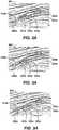
- Figures 5 and 6are images of selected cross sections to provide an enhanced estimation of the transformation vector for diapir shaped geologic objects in accordance with certain aspects of the present techniques.
- Figure 5is an exemplary image 500 of a selection of radial cross sections 510-517 through a geologic object 520.
- the dashed line 521represents that there additional cross sections in between the cross sections 510-517.
- These radial cross sections 510-517provide an enhanced estimation of the transformation vector for the diapir shaped geologic body 520. As a result, the geologic object 520 may be more accurately represented.
- Fig. 6is an exemplary image 600 of a selection of cross sections 610-617 that cross the axis of a channel 620.
- the dashed lines 621-622represent that there additional cross sections in between the cross sections 610-617.
- the cross sections 610-617provide enhanced estimation of the transformation vector for diapir shaped geologic features. As a result, the geologic object 620 may be more accurately represented.
- a first identifiermay be selected for one cross section and subsequently generated for the other cross sections.
- a second identifiermay be selected for one cross section and subsequently generated for the other cross sections.
- the second identifieris different from the first identifier, which may be one or more different points, different polyline, region or any combination.
- the identifiers generated from the two different identifiers for the other cross sectionsmay be compared to perform an uncertainty analysis.
- An exemplary method for producing hydrocarbons from a subsurface regionmay include various drilling and operational activities based on geologic objects identified from the above process.
- the drilling, development, and/or production of a hydrocarbon bearing assetmay be controlled within the subsurface region based on the predicted data from the present techniques.
- Hydrocarbonsmay be produced from the hydrocarbon bearing asset. Controlling production of the hydrocarbon bearing asset may include optimizing well location or well production.
- processor based devicessuch as digital electronic circuitry, computer hardware, firmware, software, or in any combination thereof.
- Figure 7is an exemplary processor based system 700 which is implemented to perform certain aspects of the present techniques.
- Any of the aforementioned functionalitymay be implemented as a computer program product, e.g., a computer program tangibly embodied in an information carrier, e.g., in a machine-readable storage device or in a propagated signal, for execution by, or to control the operation of, data processing apparatus, e.g., a programmable processor, a computer, or multiple computers.
- a computer programcan be written in any form of programming language, including compiled or interpreted languages, and it can be deployed in any form, including as a stand-alone program or as a module, component, subroutine, or other unit suitable for use in a computing environment.
- a computer programcan be deployed to be executed on one computer or on multiple computers at one site or distributed across multiple sites and interconnected by a communication network.
- One or more process steps of the present techniquesmay be performed by one or more programmable processors executing a computer program to perform functions of the invention by operating on input data and generating output.
- One or more stepscan also be performed by, and an apparatus or system can be implemented as, special purpose logic circuitry, e.g., an FPGA (field programmable gate array) or an ASIC (application-specific integrated circuit).
- data acquisition and displaymay be implemented through a dedicated data collection and/or processing system, e.g., containing data acquisition hardware, such as hydrophones and/or geophones, a processor(s), and various user and data input and output interfaces, such as a display component for graphically displaying one or more of the simulations and/or calculated transport properties obtained through any of the aforementioned process steps or processes.
- data acquisition hardwaresuch as hydrophones and/or geophones
- processor(s)such as a processor(s)
- various user and data input and output interfacessuch as a display component for graphically displaying one or more of the simulations and/or calculated transport properties obtained through any of the aforementioned process steps or processes.
- processors suitable for the execution of a computer programinclude, by way of example, both general and special purpose microprocessors, and any one or more processors of any kind of digital computer.
- a processorreceives instructions and data from a read-only memory or a random access memory or both.
- the essential elements of a computerare a processor for executing instructions and one or more memory devices for storing instructions and data.
- a computeralso includes, or be operatively coupled to receive data from or transfer data to, or both, one or more mass storage devices for storing data, e.g., magnetic, magneto-optical disks, or optical disks.
- Information carriers suitable for embodying computer program instructions and datainclude all forms of non-volatile memory, including by way of example semiconductor memory devices, e.g., EPROM (erasable programmable read-only memory), EEPROM (electrically erasable programmable read-only memory), and flash memory devices; magnetic disks, e.g., internal hard disks or removable disks; magneto-optical disks; and CD-ROM (compact disk read-only memory) and DVD-ROM (digital versatile disk read-only memory) disks.
- semiconductor memory devicese.g., EPROM (erasable programmable read-only memory), EEPROM (electrically erasable programmable read-only memory), and flash memory devices
- magnetic diskse.g., internal hard disks or removable disks
- magneto-optical diskse.g., magneto-optical disks
- CD-ROMcompact disk read-only memory
- DVD-ROMdigital versatile disk read-only memory
- Figure 7is an exemplary processor based system which is implemented to perform certain aspects of the present techniques.
- a system computer 710communicates with various other devices. These other devices may include storages devices, such as program storage 711, data 712, and analysis 713. These storage devices 711-713 may include instructions to perform the all or portions of the process described above.
- various input devicessuch as mouse 714 and keyboard 715, may be utilized. These input devices 714 and 715 may enable a user to enter data and extract data from the system computer 710.
- display devicessuch as printer 716 and monitor 717, may be utilized to display the data to a user. For instance, the user may view/edit cross sections through the use of the monitor 717, mouse 714 and the keyboard 715.
Landscapes
- Engineering & Computer Science (AREA)
- Physics & Mathematics (AREA)
- General Physics & Mathematics (AREA)
- Remote Sensing (AREA)
- Theoretical Computer Science (AREA)
- Computer Vision & Pattern Recognition (AREA)
- Life Sciences & Earth Sciences (AREA)
- Geology (AREA)
- General Life Sciences & Earth Sciences (AREA)
- Geophysics (AREA)
- Environmental & Geological Engineering (AREA)
- Acoustics & Sound (AREA)
- Multimedia (AREA)
- Geophysics And Detection Of Objects (AREA)
- Management, Administration, Business Operations System, And Electronic Commerce (AREA)
Description
- This description relates generally to the field of oil and gas exploration, resource development, and production planning. Specifically, this description relates to techniques useful for structural or stratigraphic interpretation of subsurface data, such as seismic data volumes, seismic derivative data volumes, or other similar data volumes. For example, the methods and techniques may be used to track boundaries of geologic objects and/or to detect geologic anomalies in a seismic and/or its derivative data volume or volumes.
- In the oil and gas industry, seismic prospecting and other similar techniques are commonly used to aid in the search for and evaluation of subterranean hydrocarbon deposits. An exemplary prospecting operation includes three stages: data acquisition, data processing, and data interpretation. The success of the prospecting operation depends on satisfactory completion of the three stages. In an exemplary data acquisition stage, a seismic source is used to generate an acoustic signal that propagates into the earth and is at least partially reflected by subsurface seismic reflectors. The reflected signals are detected and recorded by an array of seismic receivers located at or near the surface of the earth, in an overlying body of water, or at known depths in boreholes. During an exemplary data processing stage, the recorded seismic signals, e.g., seismic amplitude response, are refined and enhanced using a variety of procedures that depend on the nature of the geologic structure being investigated and on the characteristics of the raw data. In general, the purpose of the data processing stage is to produce an image of the subsurface from the recorded seismic data for use during the data interpretation stage. The purpose of the data interpretation stage is to determine information about the subsurface geology of the earth from the processed seismic data. The results of the data interpretation stage may be used to determine the general geologic structure of a subsurface region, or to locate potential hydrocarbon reservoirs, or to guide the development of an already discovered reservoir.
- To interpret, a three-dimensional (3D) data volume may be either manually interpreted or interpreted through an automated method. A "data volume" or "volume" includes one or more slices or traces (e.g. a collection of samples as a function of time (t) for one position in the earth, such as seismic traces). The collection of traces or slices forming an array are commonly referred to as "data volumes." The data volume depicts the subsurface layering of a portion of the earth. It is the principal tool that a geophysicist uses to determine the nature of the earth's subsurface formations. The data volume can be studied either by plotting it on paper or displaying it on a computer monitor. A geophysicist can then interpret the information. When displaying the data volume along a principle direction, crosslines, inlines, time slices, or horizon slices can be made. The data volume can be mathematically processed in accordance with known techniques to make subtle features in the data more discernible. The results of these processing techniques are known as "attributes." The images may also be compared over a period of time to follow the evolution of the subsurface formation over time. Either of these methods may use computer-aided interpretation tools to accelerate interpretation of prospecting data (e.g., seismic, controlled source electromagnetic, or other suitable data) for detecting geologic anomalies (e.g. geologic bodies of interest) or tracking boundaries of geologic objects of interest. These geologic objects include geologic horizon surfaces, fault surfaces, stratigraphic traps, and channels, for example.
- Manual interpretation typically involves the manual picking or digitizing of each geologic object of interest using the data volume as a visual guide. If this is done in a computer aided interpretation system, this involves digitizing the geologic objects on cross sections/slices or volumes using a cursor, tablet or some other input device. Additional seismic attribute volumes may be used to make the final interpretation. With manual interpretation, the interpreter keeps track of 3D complexity and geologic complexity. As such, this increases the risk for incorrect interpretation of geologic features and also greatly increases the time involved to complete the interpretation.
- Alternatively, automated methods for tracking geologic objects, such as horizons and faults, have existed in the industry for twenty years. However, automated methods have limitations that hinder their effectiveness for certain types of interpretation. For instance, the automated methods may not be applicable for addressing certain interpretation problems. In particular, typical automated methods require that the feature to be tracked or extended follows a consistent or similar seismic amplitude/attributes, such as peak, trough, zero crossing, within a value range. This limitation restricts the applicability of these methods, because many of the more interesting and geologically significant surfaces that need to be interpreted do not satisfy this limitation. Examples of these geologic objects include; salt/shale diapirs, channels, unconformities, and faults and other stratigraphic features. In addition, the automated systems are also limited by the data quality and the complexity of the geology. For instance, while automated methods can be more accurate than manual methods when applied to higher quality data and simple geology, these automated methods become more error prone as the data quality decreases and the complexity of the geology increases. As such, when automated results become too error prone, the amount of time required to find and correct the errors exceeds the time to manually interpret the geologic objects. Therefore, automated methods are frequently not used for large amount of interpretation tasks due to the limitations discussed above.
- The present techniques, which are described below, address weaknesses of both conventional automated methods and manual interpretation processes in tracking/extending more complex boundaries of geologic objects of interests. As a result, the present techniques may be used to reduce interpretation time, provide more accurate interpretations, and detect geologic objects (i.e. anomalous geologic regions) in prospecting data volume (e.g. seismic data and derivative volumes).
- Other related material may be found in at least
U.S. Patent Nos. 5,455,896 ;6,480,615 ;6,690,820 ;6,765,570 ;6,731,799 ;7,068,831 ;7,200,602 and7,248,258 andFitsum Admasu and Klaus Tonnies, "An Approach towards Automated Fault Interpretations in Seismic Data", SimVis 2005. The documentUS 2004/081353 A1 (LEES JACK [US] ET AL) 29 April 2004 (2004-04-29) discloses a method for creating a combination attribute volume or combo volume by combining one or more attribute volumes into a single volume. - In one general aspect, a method or a tangible computer-readable storage medium having embodied thereon a computer program configured to, when executed by a processor, identify a geologic object through cross sections of a geologic data volume is described. The method includes obtaining a geologic data volume having a set of cross sections; selecting at least two cross sections from the set of cross sections; estimating a transformation vector between the at least two cross sections within the geologic data volume; and using the estimated transformation vector to identify a geologic object within the geologic data volume. Further, using the estimated transformation vector may also include obtaining a first identifier associated with the geologic object in one of the set of cross sections; determining an additional identifier associated with the geologic object in at least one additional cross section of the set of cross sections based on the estimated transformation vector and the obtained first identifier; storing the determined identifier of the geologic object in memory, of a computer system, for instance. Also, the using the estimated transformation vector may include visualizing magnitude and direction of the estimated transformation vector to identify the geologic object within the geologic data volume.
- In one or more embodiments, the present techniques may include different aspects. For instance, the using the estimated transformation vector to identify the geologic object within the geologic data volume may include determining at least one of structural geology and stratigraphic geology associated with the geologic object within the geologic data volume. Also, the selected cross sections may are parallel to each other or may be oblique to each other. Also, the identifiers may be provided by a user the first identifier by selecting points on one of the at least two cross sections or from accessing a memory location. The identifier may include a polyline, a set of points, set of polylines, regions of a cross section and any combination thereof.
- Yet in one of more other embodiments, a second identifier associated with the geologic object may be obtained in one of the cross sections, wherein the second identifier is different from the first identifier. Then, an additional identifier associated with the geologic object may be determined in at least one additional cross section of the set of cross sections based on the estimated transformation vector and the obtained second identifier. Finally, the identifiers associated with the second identifier and the first identifier may be compared to perform an uncertainty analysis.
- Further still, in one or more other embodiments, the transformation vector may be modified for display. For instance, the magnitude and direction of transformation vector may be visualized separately. Also, the direction of transformation vector may be visualized by using a plurality of colors. The transformation vector may have colors assigned to different orthogonal directions and transformation vector's direction between two of the orthogonal directions may be assigned blended colors associated with the assigned colors for the two orthogonal directions.
Figure 1 is a flowchart of an exemplary process for identifying geologic objects (e.g. anomalies and tracking and creating geologic object boundaries) in accordance with certain aspects of the present techniques;Figure 2 is an exemplary image having an inconsistent character of the seismic data around a geologic object of interest in accordance with certain aspects of the present techniques;Figures 3A-3E are exemplary images of extending a geologic object identifier or a geologic feature in one cross section to a set of cross sections in accordance with certain aspects of the present techniques;Figure 4 is an exemplary image of the comparison of the initial geologic object indentifier and a corresponding geologic object having shape changes in the geologic object boundaries across the cross sections in accordance with certain aspects of the present techniques;Figure 5 is an exemplary radial selection of cross sections to provide enhanced estimation of the transformation vector for diapir shaped geologic object in accordance with certain aspects of the present techniques;Figure 6 is an exemplary selection of cross sections following the axis of a channel to provide enhanced estimation of the transformation vector for diapir shaped geologic object in accordance with certain aspects of the present techniques; andFigure 7 is an exemplary processor based system which is implemented to perform certain aspects of the present techniques.- One or more embodiments of the present techniques described hereinafter is based on a viewpoint that the shape and/or position of an image of geologic objects in a prospecting area (e.g. a seismic cross section) may be identified as being deformed/moved relative to its neighboring areas (e.g., neighboring seismic cross sections). Geophysical terminology used herein is known to persons skilled in the art and definitions may be found in theEncyclopedic Dictionary of Applied Geophysics by R. E. Sheriff, v. 13, by the Society of Exploration Geophysicists (Fourth Edition).
Figure 1 is aflowchart 100 for identifying geologic objects (e.g. anomalies and tracking and creating geologic object boundaries.) As used herein, "geologic objects" refers to various sedimentary features sometimes referred to as geological bodies. More generally, geological objects are three-dimensional depositional structures in subsurface geology, which are more localized than the remainder of the depositional formations. Nonlimiting examples of geologic objects include horizon surfaces, fault surfaces, stratigraphic traps, salt/shale diapirs, channels, and other stratigraphic features. It is known to model geological objects mathematically (particularly using computer programs) in a three-dimensional structural model by a closed three-dimensional boundary surface. Modeling of subsurface structures can assist in the search for and extraction of underground assets. For example, flow behavior, connected volume and overall performance of hydrocarbon reservoirs are all highly dependent on the petrophysical properties of geological objects.- The
flowchart 100 illustrates a process of obtaining an interpreted geologic object or boundaries of geologic objects in accordance with certain aspects of the present techniques. The process starts atblock 102. Atblock 104, a geologic data volume that describes a subsurface geology for a subsurface region is obtained. The geologic data volume may include a seismic data volume and its derivative data volume and any other suitable data volume. Inblock 106, a set of cross sections are selected and a sequence of the cross sections are determined. A cross section is a slice of the data volume along one path or is a slice of planar geologic object that resides in the data volume. While the cross sections may be slices of the data volume along one axis, the cross sections may also be parallel to each other or oblique to each other, as described below in discussingFigures 5 and 6 . The sequence may be determined by an ordered sequence along a specific path, or may be organized in any other suitable order. Next, inblock 108, the transformation vector, which may be a transformation vector field or an inverse transformation field, is computed by determining the shape deformation and movement of boundaries of one or more geologic objects in neighboring areas (e.g. neighboring cross sections) of a data volume. The movement vector or transformation vector field are estimated to define optimal correspondence between the two neighboring area images (e.g., neighboring cross section images). For the purpose of tracking geologic object boundaries through N neighboring cross sectionsI1 toIN, the method estimates N-1 transformation vector fieldsVi,i+1 for i=1 to N-1. Then, atblock 110, identifiers of one or more geologic objects are obtained for one of the cross sections. The identifiers may be obtained by a user (e.g., an exploration geologist) providing a boundary of a geologic object in a form of a polyline or a set of polylines,Li, at cross sectioni. Alternatively, the identifiers may be obtained from automated instructions to generate boundaries for a cross section. The identifiers may include a defined boundary, set of points, polyline, set of polylines, and defined region of the cross section or any combination. - Once the identifiers are obtained for the cross section, the transformation vector, which may be transformation vector fieldsVi,i+1 or its inverse transformation vector fieldsVi+1,i, for i=1 to N-1, is used to calculate the geologic object boundaries in the other neighboring cross sections, as shown in
block 112. Here, a transformation vector fieldVi,i+1 represents an optimal correspondence from an image or seismic amplitudes at cross section i to an image or seismic amplitudes at cross section i+1. The inverse transformation vector fieldsVi+1,i represents an optimal correspondence from cross section i+1 to cross section i. Compared to the conventional point-to-point correlation methods for tracking a boundary of a geologic object, such as automated horizon tracking methods, the present technique is a holistic approach that determines pixel to pixel correspondence of a cross section to a neighboring cross section. This is comparable to interpreting each of geologic objects (e.g., structures) together with their contextual relationships instead of interpreting one geologic structure without considering its spatial relationship to other geologic structures. Under the present techniques, neighboring cross sections may be parallel to each other or neighboring cross sections may be oblique to each other. Also, more than one neighboring cross section may be used to estimate transformation vector field between two cross sections. Furthermore, more than one polyline may be used to describe a geologic object or multiple polylines may be provided to describe multiple geologic objects. - Alternatively, as in
block 114, the magnitudes and direction of the computed transformation vector may be display. In thisblock 114, the magnitudes and direction of the estimated transformation vector fields,Vi,i+1 i=1 to N-1, is useful in visualizing and detecting trends in geologic objects, such as subsurface geology and subsurface anomalies, which are often associated with hydrocarbon discovery. Atblock 116, trends in the structural or stratigraphic geology are identified. One example is a sub-channel that is embedded in a channel and moving in a different direction from the main region of the channel in neighboring cross sections. Another example is a channel cutting through a sloped horizon layers. In this example, the sloped horizons boundaries in neighboring cross sections move up (or down) through the neighboring cross sections, while the channel boundary may not move up (or down) at the same rate. These movement discrepancies among different geologic objects can be detected by visualizing the transformation vectors in color code and co-rendering them with seismic data amplitudes. For instance, the transformation vector may be assigned distinct colors for different orthogonal directions. The transformation vector between two of the orthogonal directions may also be assigned a blended colors associated with the assigned colors for the two orthogonal directions. In this manner, the transformation vector may be clearly visualized for a user. - Regardless, the identified boundary of the geologic objects may be used to produce hydrocarbons, as shown in
block 120. The boundaries of the geologic objects may be incorporated into a model to identify one or more potential hydrocarbon-bearing zones within a reservoir. Once a hydrocarbon-bearing zones is predicted to exist, one or more wells may be drilled to access and produce the hydrocarbons from the reservoir. The process ends atblock 122. - As noted above, several known technologies may be used to estimate the transformation vector field or to warping parameters of an image (e.g. cross section) for matching the next image (e.g. neighboring cross section). These technologies include image block matching algorithms (SeeImage and Video Compression for Multimedia Engineering: Fundamentals, Algorithms, and Standards, Yun Q. Shi, Huifang Sun, CRC Press, 2000) and image registration methods (See Image registration methods: a survey, Barbara Zitova, Jan Flusser, Image and Vision Computing 21, p977-1000, 2003 andA survey of image registration techniques, Lisa Gottesfeld Brown, ACM Computing Surveys, Vol. 24, Issue 4 (December 1992), p325-376, ACM Publisher.)
- The following describes one exemplary embodiment of estimating the transformation vector field between neighboring cross sections. This description is only for an illustrative purpose, as estimating transformation vector fields may be performed in various other methods. To begin, the transformation vector fieldVi,i+1 is estimated by minimizing an objective function of equation (1), which is as follows:

- For images or cross sections of large deformations, a gradient-based energy minimization methods often converge to local minima providing an inaccurate transformation vector field. In the image processing technical area, a multiscale or a multilevel methods may be used to speedup the convergence and to avoid local minimum solution to equation (1) above. One of the objectives of these methods is that the transformation vector is estimated at different resolutions or scales of two images or cross sections, usually coarse-to-fine scale. These multiscale or multilevel image registration methods are utilized in industry (See, e.g.,Towards fast non-rigid registration,U. Clarenz, M. Droske, and M. Rumpf, in Inverse Problems, Image Analysis and Medical Imaging, AMS Special Session Interaction of Inverse Problems and Image Analysis, volume 313, pp.67-84, AMS,2002; and Iterative multigrid regularization techniques for image matching, Stefan Henn and Kristian Witsch, SIAM J. Sci. Comput., 23(4):1077-1093, 2001).
- As an example of the process described in
Figure 1 ,Figures 2 ,3A-3E and4 further illustrate certain aspects of the present techniques.Figure 2 is anexemplary image 200 having an inconsistent or anomalous character of the seismic data around a geologic object of interest in accordance with certain aspects of the present techniques. In thisimage 200, the inconsistent character of the seismic data around a geologic object of interest is shown. Theimage 200 is a cross section or slice through a 3D seismic amplitude volume. The seismic amplitude values are displayed using a grayscale color mapping. The white regions W in theimage 200 are associated with high negative seismic amplitudes and black regions B in theimage 200 are associated with high positive amplitudes. Also shown in thisimage 200 is an initial set of points connected together to create apolyline 210 that defines a geologic object. Thepolyline 210 may be obtained, as discussed above inblock 110. Arrows 220-227 are directed to points identified as part of the polyline 210 (e.g., white regions W, black regions B, peak to trough regions W->B, and trough to peak regions B->W) that exemplify the inconsistent seismic character associated in the area around polyline. Please note that conventional automated horizon and fault tracking algorithms are limited and do not track the feature of interest (e.g., polyline) due to the variable seismic character of peaks, troughs, and zero crossing (both going fromtroughs to peaks andpeaks to troughs). Figures 3A-3E are exemplary images of extending a geologic object boundary or a geologic object in one cross section to a set of cross sections in accordance with certain aspects of the present techniques.Figures 3A-3E are images 301-305 results from the present techniques to extend a geologic object (e.g. polyline 310a-310e) from theimage 301 of the first cross section or slice to the other images 302-305 (e.g. additional cross sections or slices). The seismic data in the images 301-305 is displayed using the same visualization parameters utilized inFigure 2 .Arrows 320a-320e, 321a-321e, 322a-322e, 323a-323e and 325a-325e are added to indicate points along the polyline associated with the geologic object's location. Inimage 301, the slice contains theinitial starting polyline 310a of a geologic object, which is associated with the same geologic object's boundary shown inFigure 2 . The subsequent images 302-305 include the results of using the transformation vector to project the position of the startingpolyline 310a to the corresponding images 302-305. The projectedpolylines 310b-310e in these images 302-305 produce a final interpretation which closely matches the results if this object were interpreted manually, but is performed more efficiently.Figure 4 is anexemplary image 400 of the comparison of the initial geologic object boundary (e.g. polyline 410) and a corresponding geologic object boundary (e.g., polyline 420) having shape changes in the geologic object boundaries across the cross sections in accordance with certain aspects of the present techniques. In theimage 400, a comparison of theinitial starting polyline 410 and projectedpolyline 420 is shown. As is evident, the starting ororiginal polyline 410 has moved at non-uniform distances to the updatedpolyline 420. That is, thepolyline 410 has moved down and to the right by differing values to align with the seismic character. The revisedpolyine 420 appears to have a more consistent trough or trough-peak character.- As discussed above in other exemplary applications, the cross sections may be parallel to each other or oblique to each other.
Figures 5 and 6 are images of selected cross sections to provide an enhanced estimation of the transformation vector for diapir shaped geologic objects in accordance with certain aspects of the present techniques. In particular,Figure 5 is anexemplary image 500 of a selection of radial cross sections 510-517 through a geologic object 520. The dashedline 521 represents that there additional cross sections in between the cross sections 510-517. These radial cross sections 510-517 provide an enhanced estimation of the transformation vector for the diapir shaped geologic body 520. As a result, the geologic object 520 may be more accurately represented. Fig. 6 is anexemplary image 600 of a selection of cross sections 610-617 that cross the axis of achannel 620. The dashed lines 621-622 represent that there additional cross sections in between the cross sections 610-617. In thisimage 600, the cross sections 610-617 provide enhanced estimation of the transformation vector for diapir shaped geologic features. As a result, thegeologic object 620 may be more accurately represented.- Further, the above mentioned process may be used to provide some uncertainty analysis. For instance, a first identifier may be selected for one cross section and subsequently generated for the other cross sections. Then, a second identifier may be selected for one cross section and subsequently generated for the other cross sections. The second identifier is different from the first identifier, which may be one or more different points, different polyline, region or any combination. Then, the identifiers generated from the two different identifiers for the other cross sections may be compared to perform an uncertainty analysis.
- An exemplary method for producing hydrocarbons from a subsurface region may include various drilling and operational activities based on geologic objects identified from the above process. The drilling, development, and/or production of a hydrocarbon bearing asset may be controlled within the subsurface region based on the predicted data from the present techniques. Hydrocarbons may be produced from the hydrocarbon bearing asset. Controlling production of the hydrocarbon bearing asset may include optimizing well location or well production.
- One or more of the aforementioned processes and/or techniques to generate geologic bodies for a data volume may be implemented in processor based devices, such as digital electronic circuitry, computer hardware, firmware, software, or in any combination thereof.
Figure 7 is an exemplary processor basedsystem 700 which is implemented to perform certain aspects of the present techniques. Any of the aforementioned functionality may be implemented as a computer program product, e.g., a computer program tangibly embodied in an information carrier, e.g., in a machine-readable storage device or in a propagated signal, for execution by, or to control the operation of, data processing apparatus, e.g., a programmable processor, a computer, or multiple computers. A computer program can be written in any form of programming language, including compiled or interpreted languages, and it can be deployed in any form, including as a stand-alone program or as a module, component, subroutine, or other unit suitable for use in a computing environment. A computer program can be deployed to be executed on one computer or on multiple computers at one site or distributed across multiple sites and interconnected by a communication network. - One or more process steps of the present techniques may be performed by one or more programmable processors executing a computer program to perform functions of the invention by operating on input data and generating output. One or more steps can also be performed by, and an apparatus or system can be implemented as, special purpose logic circuitry, e.g., an FPGA (field programmable gate array) or an ASIC (application-specific integrated circuit). In addition, data acquisition and display may be implemented through a dedicated data collection and/or processing system, e.g., containing data acquisition hardware, such as hydrophones and/or geophones, a processor(s), and various user and data input and output interfaces, such as a display component for graphically displaying one or more of the simulations and/or calculated transport properties obtained through any of the aforementioned process steps or processes.
- Processors suitable for the execution of a computer program include, by way of example, both general and special purpose microprocessors, and any one or more processors of any kind of digital computer. Generally, a processor receives instructions and data from a read-only memory or a random access memory or both. The essential elements of a computer are a processor for executing instructions and one or more memory devices for storing instructions and data. Generally, a computer also includes, or be operatively coupled to receive data from or transfer data to, or both, one or more mass storage devices for storing data, e.g., magnetic, magneto-optical disks, or optical disks. Information carriers suitable for embodying computer program instructions and data include all forms of non-volatile memory, including by way of example semiconductor memory devices, e.g., EPROM (erasable programmable read-only memory), EEPROM (electrically erasable programmable read-only memory), and flash memory devices; magnetic disks, e.g., internal hard disks or removable disks; magneto-optical disks; and CD-ROM (compact disk read-only memory) and DVD-ROM (digital versatile disk read-only memory) disks. The processor and the memory can be supplemented by, or incorporated in special purpose logic circuitry.
- As an example,
Figure 7 is an exemplary processor based system which is implemented to perform certain aspects of the present techniques. In thissystem 700, a system computer 710 communicates with various other devices. These other devices may include storages devices, such asprogram storage 711,data 712, andanalysis 713. These storage devices 711-713 may include instructions to perform the all or portions of the process described above. To interact with the system computer 710 various input devices, such asmouse 714 andkeyboard 715, may be utilized. Theseinput devices printer 716 and monitor 717, may be utilized to display the data to a user. For instance, the user may view/edit cross sections through the use of themonitor 717,mouse 714 and thekeyboard 715. - All such modifications and variations are intended to be within the scope of the appended claims. Persons skilled in the art will also readily recognize that in preferred embodiments, at least some of the steps are performed on a computer, e.g., the exemplary processes may be computer implemented. In such cases, the resulting model parameters may either be downloaded or saved to computer memory.

Claims (14)
- A computer-implemented method for obtaining an interpreted geologic object or boundaries of geological objects comprising the steps of:obtaining a geologic data volume having a set of cross sections;selecting at least two cross sections from the set of cross sections; andobtaining a first identifier associated with a geologic object in one of the set of cross sections;characterized in that the method further comprises:estimating a transformation vector between the at least two cross sections within the geologic data volume, wherein the transformation vector determines a pixel to pixel correspondence between a first cross section and a second cross section and is determined by shape deformation and movement of boundaries of the geologic object in the second cross section relative to the first cross section;determining an additional identifier associated with the geologic object in at least one additional cross section of the set of cross sections based on the estimated transformation vector and the obtained first identifier;storing the determined identifier of the geologic object in memory;using the transformation vector to calculate the geologic object boundaries; andincorporating the boundaries of the geologic object into a model to identify one or more potential hydrocarbon-bearing zones within a reservoir.
- The method of claim 1, wherein using the estimated transformation vector to identify the geologic object within the geologic data volume further comprises determining at least one of structural geology and stratigraphic geology associated with the geologic object within the geologic data volume.
- The method of claim 1, wherein using the estimated transformation vector further comprises visualizing magnitude and direction of the estimated transformation vector to identify the geologic object within the geologic data volume.
- The method of claim 1, wherein the selected at least two cross sections are parallel to each other.
- The method of claim 1, wherein the selected at least two cross sections are oblique to each other.
- The method of claim 1, wherein obtaining the first identifier associated with the geologic object in one of the set of cross sections comprises a user providing the first identifier by selecting points on one of the at least two cross sections.
- The method in claim 1, wherein obtaining the first identifier associated with the geologic object in one of the set of cross sections comprises obtaining the identifier from a memory location.
- The method in claim 1, wherein the first identifier is one of a polyline, a set of points, a set of polylines, regions of a cross section, and any combination thereof.
- The method in claim 1, further comprising:obtaining a second identifier associated with the geologic object in one of the set of cross sections, wherein the second identifier is different from the first identifier;determining an additional identifier associated with the geologic object in at least one additional cross section of the set of cross sections based on the estimated transformation vector and the obtained second identifier;comparing the identifiers associated with the second identifier and the identifiers associated with the first identifier to perform an uncertainty analysis.
- The method in claim 3, wherein magnitude and direction of transformation vector are visualized separately.
- The method in claim 3, wherein direction of transformation vector is visualized by using a plurality of colors.
- The method in claim 10, wherein the transformation vector is assigned distinct colors for different orthogonal directions and the transformation vector between two orthogonal directions is assigned blended colors associated with the assigned distinct colors for the two orthogonal directions.
- The method of claim 1, further comprising acquiring seismic data representative of the subsurface region.
- A method for producing hydrocarbons from a subsurface region, comprising performing a method of identifying a geological object through cross sections of a geologic data volume of said subsurface region as defined in any of the preceding claims, drilling a well based on the geologic object; and producing hydrocarbons from the hydrocarbon bearing asset.
Applications Claiming Priority (2)
| Application Number | Priority Date | Filing Date | Title |
|---|---|---|---|
| US10837508P | 2008-10-24 | 2008-10-24 | |
| PCT/US2009/049553WO2010047856A1 (en) | 2008-10-24 | 2009-07-02 | Tracking geologic object and detecting geologic anomalies in exploration seismic data volume |
Publications (3)
| Publication Number | Publication Date |
|---|---|
| EP2350901A1 EP2350901A1 (en) | 2011-08-03 |
| EP2350901A4 EP2350901A4 (en) | 2017-04-26 |
| EP2350901B1true EP2350901B1 (en) | 2019-09-04 |
Family
ID=42119593
Family Applications (1)
| Application Number | Title | Priority Date | Filing Date |
|---|---|---|---|
| EP09822354.8AActiveEP2350901B1 (en) | 2008-10-24 | 2009-07-02 | Tracking geologic object and detecting geologic anomalies in exploration seismic data volume |
Country Status (5)
| Country | Link |
|---|---|
| US (1) | US9022129B2 (en) |
| EP (1) | EP2350901B1 (en) |
| AU (1) | AU2009308037B2 (en) |
| CA (1) | CA2733729C (en) |
| WO (1) | WO2010047856A1 (en) |
Families Citing this family (13)
| Publication number | Priority date | Publication date | Assignee | Title |
|---|---|---|---|---|
| CA2717514C (en) | 2008-05-05 | 2016-07-26 | Exxonmobil Upstream Research Company | Systems and methods for connectivity analysis using functional objects |
| CA2850984A1 (en) | 2011-11-11 | 2013-05-16 | Exxonmobil Upstream Research Company | Method of generating and combining multiple horizons to determine a seismic horizon and its uncertainty |
| CN102819688A (en)* | 2012-08-29 | 2012-12-12 | 电子科技大学 | Two-dimensional seismic data full-layer tracking method based on semi-supervised classification |
| WO2016137888A1 (en)* | 2015-02-23 | 2016-09-01 | Schlumberger Technology Corporation | Visualizing datasets |
| US10036820B2 (en) | 2016-03-04 | 2018-07-31 | General Electric Company | Expert guided knowledge acquisition system for analyzing seismic data |
| US10261205B2 (en) | 2016-08-03 | 2019-04-16 | Harris Corporation | System for processing seismic data based upon volatility measurement model and related methods |
| US10871585B2 (en) | 2016-08-03 | 2020-12-22 | Harris Corporation | System for processing seismic data based upon linear optimization and related methods |
| US10628703B2 (en) | 2017-12-19 | 2020-04-21 | International Business Machines Corporation | Identifying temporal changes of industrial objects by matching images |
| US11662501B2 (en) | 2018-04-03 | 2023-05-30 | ExxonMobil Technology and Engineering Company | Geologic modeling methods and systems having constrained restoration of depositional space |
| CN111796324B (en) | 2019-04-09 | 2023-02-10 | 中国石油天然气股份有限公司 | Seismic all-horizon tracking method and device |
| WO2021258096A1 (en)* | 2020-06-19 | 2021-12-23 | Exxonmobil Upstream Research Company | Classifying geologic features in seismic data through image analysis by neural network |
| US11927709B2 (en) | 2021-02-02 | 2024-03-12 | Saudi Arabian Oil Company | Multi-scale geological modeling and well information integration |
| US12421829B2 (en) | 2021-09-21 | 2025-09-23 | Saudi Arabian Oil Company | Combined carbon dioxide disposal and freshwater production from a saline aquifer |
Family Cites Families (26)
| Publication number | Priority date | Publication date | Assignee | Title |
|---|---|---|---|---|
| US4646239A (en)* | 1984-07-20 | 1987-02-24 | Standard Oil Company | Method of seismic exploration including processing and displaying seismic data to quantitatively distinguish among seismic events |
| JP3059495B2 (en) | 1991-01-17 | 2000-07-04 | 株式会社リコー | 3D shape processing method |
| US5537320A (en) | 1994-10-31 | 1996-07-16 | Landmark Graphics Corporation | Method and apparatus for identifying fault curves in seismic data |
| US5704713A (en) | 1995-08-08 | 1998-01-06 | Exxon Production Research Company | Reconstruction of geologic thermal histories |
| FR2757957B1 (en)* | 1996-12-30 | 1999-01-29 | Inst Francais Du Petrole | METHOD FOR SIMPLIFYING THE MODELING OF A POROUS GEOLOGICAL ENVIRONMENT CROSSED BY AN IRREGULAR FRACTURE NETWORK |
| US6249616B1 (en)* | 1997-05-30 | 2001-06-19 | Enroute, Inc | Combining digital images based on three-dimensional relationships between source image data sets |
| US5987388A (en) | 1997-12-26 | 1999-11-16 | Atlantic Richfield Company | Automated extraction of fault surfaces from 3-D seismic prospecting data |
| US6765570B1 (en) | 1998-07-21 | 2004-07-20 | Magic Earth, Inc. | System and method for analyzing and imaging three-dimensional volume data sets using a three-dimensional sampling probe |
| US6018498A (en) | 1998-09-02 | 2000-01-25 | Phillips Petroleum Company | Automated seismic fault detection and picking |
| US6754588B2 (en)* | 1999-01-29 | 2004-06-22 | Platte River Associates, Inc. | Method of predicting three-dimensional stratigraphy using inverse optimization techniques |
| US6140643A (en) | 1999-03-09 | 2000-10-31 | Exxonmobil Upstream Research Company | Method for identification of unknown substances |
| US6480615B1 (en) | 1999-06-15 | 2002-11-12 | University Of Washington | Motion estimation within a sequence of data frames using optical flow with adaptive gradients |
| US6611615B1 (en)* | 1999-06-25 | 2003-08-26 | University Of Iowa Research Foundation | Method and apparatus for generating consistent image registration |
| US6549879B1 (en) | 1999-09-21 | 2003-04-15 | Mobil Oil Corporation | Determining optimal well locations from a 3D reservoir model |
| US6442487B2 (en) | 1999-12-06 | 2002-08-27 | Exxonmobil Upstream Research Company | Reliability measures for statistical prediction of geophysical and geological parameters in geophysical prospecting |
| US6731799B1 (en) | 2000-06-01 | 2004-05-04 | University Of Washington | Object segmentation with background extraction and moving boundary techniques |
| WO2002019268A2 (en) | 2000-08-31 | 2002-03-07 | Koninklijke Philips Electronics N.V. | Extracting a string of points following a threadlike structure in a sequence of images |
| US7006085B1 (en) | 2000-10-30 | 2006-02-28 | Magic Earth, Inc. | System and method for analyzing and imaging three-dimensional volume data sets |
| US6690820B2 (en) | 2001-01-31 | 2004-02-10 | Magic Earth, Inc. | System and method for analyzing and imaging and enhanced three-dimensional volume data set using one or more attributes |
| EP1570423A2 (en) | 2002-10-18 | 2005-09-07 | ExxonMobil Upstream Research Company | A method for rapid fault interpretation of fault surfaces generated to fit three-dimensional seismic discontinuity data |
| US7200602B2 (en) | 2003-02-07 | 2007-04-03 | International Business Machines Corporation | Data set comparison and net change processing |
| US7409108B2 (en)* | 2003-09-22 | 2008-08-05 | Siemens Medical Solutions Usa, Inc. | Method and system for hybrid rigid registration of 2D/3D medical images |
| EA010952B1 (en) | 2005-05-26 | 2008-12-30 | Эксонмобил Апстрим Рисерч Компани | A rapid method for reservoir connectivity analysis using a fast marching method |
| US8365831B2 (en) | 2007-12-18 | 2013-02-05 | Exxonmobil Upstream Research Company | Determining connectivity architecture in 2-D and 3-D heterogeneous data |
| EP2252903A4 (en) | 2008-03-10 | 2018-01-03 | Exxonmobil Upstream Research Company | Method for determing distinct alternative paths between two object sets in 2-d and 3-d heterogeneous data |
| AU2009238481B2 (en) | 2008-04-22 | 2014-01-30 | Exxonmobil Upstream Research Company | Functional-based knowledge analysis in a 2D and 3D visual environment |
- 2009
- 2009-07-02EPEP09822354.8Apatent/EP2350901B1/enactiveActive
- 2009-07-02USUS13/059,780patent/US9022129B2/enactiveActive
- 2009-07-02AUAU2009308037Apatent/AU2009308037B2/enactiveActive
- 2009-07-02WOPCT/US2009/049553patent/WO2010047856A1/enactiveApplication Filing
- 2009-07-02CACA2733729Apatent/CA2733729C/enactiveActive
Non-Patent Citations (1)
| Title |
|---|
| None* |
Also Published As
| Publication number | Publication date |
|---|---|
| AU2009308037A1 (en) | 2010-04-29 |
| US20110247829A1 (en) | 2011-10-13 |
| EP2350901A1 (en) | 2011-08-03 |
| AU2009308037B2 (en) | 2015-04-30 |
| CA2733729C (en) | 2017-01-17 |
| EP2350901A4 (en) | 2017-04-26 |
| WO2010047856A1 (en) | 2010-04-29 |
| CA2733729A1 (en) | 2010-04-29 |
| US9022129B2 (en) | 2015-05-05 |
Similar Documents
| Publication | Publication Date | Title |
|---|---|---|
| EP2350901B1 (en) | Tracking geologic object and detecting geologic anomalies in exploration seismic data volume | |
| Thore et al. | Structural uncertainties: Determination, management, and applications | |
| EP3682269B1 (en) | Seismic image data interpretation system | |
| Wu et al. | Deep learning for characterizing paleokarst collapse features in 3‐D seismic images | |
| Gao | Integrating 3D seismic curvature and curvature gradient attributes for fracture characterization: Methodologies and interpretational implications | |
| West et al. | Interactive seismic facies classification using textural attributes and neural networks | |
| EP3408691B1 (en) | Feature index-based feature detection | |
| EP3298437A1 (en) | Inversion for tectonic stress | |
| EP3436849B1 (en) | Determining displacement between seismic images using optical flow | |
| WO2016126453A1 (en) | Seismic attributes derived from the relative geological age property of a volume-based model | |
| EP3436850B1 (en) | Determining displacement between seismic images using optical flow | |
| de Kemp et al. | Assessing the workflow for regional-scale 3D geologic modeling: An example from the Sullivan time horizon, Purcell Anticlinorium East Kootenay region, southeastern British Columbia | |
| Schneider et al. | Interpretation of fractured zones using seismic attributes—Case study from Teapot Dome, Wyoming, USA | |
| US11630226B2 (en) | Formation evaluation based on seismic horizon mapping with multi-scale optimization | |
| KR20150088816A (en) | System and method for velocity anomaly analysis | |
| US11880008B2 (en) | Velocity model construction | |
| Johansen | Composition of seismic facies: A case study | |
| US20240111067A1 (en) | Faulted seismic horizon mapping | |
| Ebuna et al. | Statistical approach to neural network imaging of karst systems in 3D seismic reflection data | |
| Abdelfattah | Advancing Fractured Reservoir Characterization: A Reservoir-Driven Seismic Reprocessing Approach | |
| Greenhalgh et al. | Velocity field imaging with an anomaly recovery algorithm, incorporating later arrivals |
Legal Events
| Date | Code | Title | Description |
|---|---|---|---|
| PUAI | Public reference made under article 153(3) epc to a published international application that has entered the european phase | Free format text:ORIGINAL CODE: 0009012 | |
| 17P | Request for examination filed | Effective date:20110505 | |
| AK | Designated contracting states | Kind code of ref document:A1 Designated state(s):AT BE BG CH CY CZ DE DK EE ES FI FR GB GR HR HU IE IS IT LI LT LU LV MC MK MT NL NO PL PT RO SE SI SK SM TR | |
| DAX | Request for extension of the european patent (deleted) | ||
| RAP1 | Party data changed (applicant data changed or rights of an application transferred) | Owner name:EXXONMOBIL UPSTREAM RESEARCH COMPANY | |
| RA4 | Supplementary search report drawn up and despatched (corrected) | Effective date:20170324 | |
| RIC1 | Information provided on ipc code assigned before grant | Ipc:G06F 19/00 20110101AFI20170320BHEP | |
| STAA | Information on the status of an ep patent application or granted ep patent | Free format text:STATUS: EXAMINATION IS IN PROGRESS | |
| 17Q | First examination report despatched | Effective date:20171201 | |
| REG | Reference to a national code | Ref country code:DE Ref legal event code:R079 Ref document number:602009059746 Country of ref document:DE Free format text:PREVIOUS MAIN CLASS: G06F0019000000 Ipc:G01V0001300000 | |
| GRAP | Despatch of communication of intention to grant a patent | Free format text:ORIGINAL CODE: EPIDOSNIGR1 | |
| STAA | Information on the status of an ep patent application or granted ep patent | Free format text:STATUS: GRANT OF PATENT IS INTENDED | |
| RIC1 | Information provided on ipc code assigned before grant | Ipc:G01V 1/30 20060101AFI20190129BHEP Ipc:G06T 7/11 20170101ALI20190129BHEP Ipc:G06T 7/269 20170101ALI20190129BHEP Ipc:G06T 7/30 20170101ALI20190129BHEP | |
| INTG | Intention to grant announced | Effective date:20190222 | |
| RIN1 | Information on inventor provided before grant (corrected) | Inventor name:WHITAKER, ROSS Inventor name:KIM, CHUL-SUNG Inventor name:DOBIN, MARK, W. | |
| GRAS | Grant fee paid | Free format text:ORIGINAL CODE: EPIDOSNIGR3 | |
| GRAJ | Information related to disapproval of communication of intention to grant by the applicant or resumption of examination proceedings by the epo deleted | Free format text:ORIGINAL CODE: EPIDOSDIGR1 | |
| GRAL | Information related to payment of fee for publishing/printing deleted | Free format text:ORIGINAL CODE: EPIDOSDIGR3 | |
| STAA | Information on the status of an ep patent application or granted ep patent | Free format text:STATUS: EXAMINATION IS IN PROGRESS | |
| GRAR | Information related to intention to grant a patent recorded | Free format text:ORIGINAL CODE: EPIDOSNIGR71 | |
| STAA | Information on the status of an ep patent application or granted ep patent | Free format text:STATUS: GRANT OF PATENT IS INTENDED | |
| INTC | Intention to grant announced (deleted) | ||
| GRAA | (expected) grant | Free format text:ORIGINAL CODE: 0009210 | |
| STAA | Information on the status of an ep patent application or granted ep patent | Free format text:STATUS: THE PATENT HAS BEEN GRANTED | |
| INTG | Intention to grant announced | Effective date:20190724 | |
| AK | Designated contracting states | Kind code of ref document:B1 Designated state(s):AT BE BG CH CY CZ DE DK EE ES FI FR GB GR HR HU IE IS IT LI LT LU LV MC MK MT NL NO PL PT RO SE SI SK SM TR | |
| REG | Reference to a national code | Ref country code:GB Ref legal event code:FG4D | |
| REG | Reference to a national code | Ref country code:CH Ref legal event code:EP | |
| REG | Reference to a national code | Ref country code:AT Ref legal event code:REF Ref document number:1176146 Country of ref document:AT Kind code of ref document:T Effective date:20190915 | |
| REG | Reference to a national code | Ref country code:DE Ref legal event code:R096 Ref document number:602009059746 Country of ref document:DE | |
| REG | Reference to a national code | Ref country code:IE Ref legal event code:FG4D | |
| REG | Reference to a national code | Ref country code:NL Ref legal event code:FP | |
| REG | Reference to a national code | Ref country code:LT Ref legal event code:MG4D Ref country code:NO Ref legal event code:T2 Effective date:20190904 | |
| PG25 | Lapsed in a contracting state [announced via postgrant information from national office to epo] | Ref country code:SE Free format text:LAPSE BECAUSE OF FAILURE TO SUBMIT A TRANSLATION OF THE DESCRIPTION OR TO PAY THE FEE WITHIN THE PRESCRIBED TIME-LIMIT Effective date:20190904 Ref country code:HR Free format text:LAPSE BECAUSE OF FAILURE TO SUBMIT A TRANSLATION OF THE DESCRIPTION OR TO PAY THE FEE WITHIN THE PRESCRIBED TIME-LIMIT Effective date:20190904 Ref country code:LT Free format text:LAPSE BECAUSE OF FAILURE TO SUBMIT A TRANSLATION OF THE DESCRIPTION OR TO PAY THE FEE WITHIN THE PRESCRIBED TIME-LIMIT Effective date:20190904 Ref country code:FI Free format text:LAPSE BECAUSE OF FAILURE TO SUBMIT A TRANSLATION OF THE DESCRIPTION OR TO PAY THE FEE WITHIN THE PRESCRIBED TIME-LIMIT Effective date:20190904 Ref country code:BG Free format text:LAPSE BECAUSE OF FAILURE TO SUBMIT A TRANSLATION OF THE DESCRIPTION OR TO PAY THE FEE WITHIN THE PRESCRIBED TIME-LIMIT Effective date:20191204 | |
| PG25 | Lapsed in a contracting state [announced via postgrant information from national office to epo] | Ref country code:ES Free format text:LAPSE BECAUSE OF FAILURE TO SUBMIT A TRANSLATION OF THE DESCRIPTION OR TO PAY THE FEE WITHIN THE PRESCRIBED TIME-LIMIT Effective date:20190904 Ref country code:LV Free format text:LAPSE BECAUSE OF FAILURE TO SUBMIT A TRANSLATION OF THE DESCRIPTION OR TO PAY THE FEE WITHIN THE PRESCRIBED TIME-LIMIT Effective date:20190904 Ref country code:GR Free format text:LAPSE BECAUSE OF FAILURE TO SUBMIT A TRANSLATION OF THE DESCRIPTION OR TO PAY THE FEE WITHIN THE PRESCRIBED TIME-LIMIT Effective date:20191205 | |
| REG | Reference to a national code | Ref country code:AT Ref legal event code:MK05 Ref document number:1176146 Country of ref document:AT Kind code of ref document:T Effective date:20190904 | |
| PG25 | Lapsed in a contracting state [announced via postgrant information from national office to epo] | Ref country code:PT Free format text:LAPSE BECAUSE OF FAILURE TO SUBMIT A TRANSLATION OF THE DESCRIPTION OR TO PAY THE FEE WITHIN THE PRESCRIBED TIME-LIMIT Effective date:20200106 Ref country code:IT Free format text:LAPSE BECAUSE OF FAILURE TO SUBMIT A TRANSLATION OF THE DESCRIPTION OR TO PAY THE FEE WITHIN THE PRESCRIBED TIME-LIMIT Effective date:20190904 Ref country code:RO Free format text:LAPSE BECAUSE OF FAILURE TO SUBMIT A TRANSLATION OF THE DESCRIPTION OR TO PAY THE FEE WITHIN THE PRESCRIBED TIME-LIMIT Effective date:20190904 Ref country code:AT Free format text:LAPSE BECAUSE OF FAILURE TO SUBMIT A TRANSLATION OF THE DESCRIPTION OR TO PAY THE FEE WITHIN THE PRESCRIBED TIME-LIMIT Effective date:20190904 Ref country code:EE Free format text:LAPSE BECAUSE OF FAILURE TO SUBMIT A TRANSLATION OF THE DESCRIPTION OR TO PAY THE FEE WITHIN THE PRESCRIBED TIME-LIMIT Effective date:20190904 Ref country code:PL Free format text:LAPSE BECAUSE OF FAILURE TO SUBMIT A TRANSLATION OF THE DESCRIPTION OR TO PAY THE FEE WITHIN THE PRESCRIBED TIME-LIMIT Effective date:20190904 | |
| PG25 | Lapsed in a contracting state [announced via postgrant information from national office to epo] | Ref country code:IS Free format text:LAPSE BECAUSE OF FAILURE TO SUBMIT A TRANSLATION OF THE DESCRIPTION OR TO PAY THE FEE WITHIN THE PRESCRIBED TIME-LIMIT Effective date:20200224 Ref country code:SM Free format text:LAPSE BECAUSE OF FAILURE TO SUBMIT A TRANSLATION OF THE DESCRIPTION OR TO PAY THE FEE WITHIN THE PRESCRIBED TIME-LIMIT Effective date:20190904 Ref country code:SK Free format text:LAPSE BECAUSE OF FAILURE TO SUBMIT A TRANSLATION OF THE DESCRIPTION OR TO PAY THE FEE WITHIN THE PRESCRIBED TIME-LIMIT Effective date:20190904 Ref country code:CZ Free format text:LAPSE BECAUSE OF FAILURE TO SUBMIT A TRANSLATION OF THE DESCRIPTION OR TO PAY THE FEE WITHIN THE PRESCRIBED TIME-LIMIT Effective date:20190904 | |
| REG | Reference to a national code | Ref country code:DE Ref legal event code:R097 Ref document number:602009059746 Country of ref document:DE | |
| PLBE | No opposition filed within time limit | Free format text:ORIGINAL CODE: 0009261 | |
| STAA | Information on the status of an ep patent application or granted ep patent | Free format text:STATUS: NO OPPOSITION FILED WITHIN TIME LIMIT | |
| PG2D | Information on lapse in contracting state deleted | Ref country code:IS | |
| PG25 | Lapsed in a contracting state [announced via postgrant information from national office to epo] | Ref country code:DK Free format text:LAPSE BECAUSE OF FAILURE TO SUBMIT A TRANSLATION OF THE DESCRIPTION OR TO PAY THE FEE WITHIN THE PRESCRIBED TIME-LIMIT Effective date:20190904 Ref country code:IS Free format text:LAPSE BECAUSE OF FAILURE TO SUBMIT A TRANSLATION OF THE DESCRIPTION OR TO PAY THE FEE WITHIN THE PRESCRIBED TIME-LIMIT Effective date:20200105 | |
| 26N | No opposition filed | Effective date:20200605 | |
| PG25 | Lapsed in a contracting state [announced via postgrant information from national office to epo] | Ref country code:SI Free format text:LAPSE BECAUSE OF FAILURE TO SUBMIT A TRANSLATION OF THE DESCRIPTION OR TO PAY THE FEE WITHIN THE PRESCRIBED TIME-LIMIT Effective date:20190904 | |
| REG | Reference to a national code | Ref country code:DE Ref legal event code:R119 Ref document number:602009059746 Country of ref document:DE | |
| PG25 | Lapsed in a contracting state [announced via postgrant information from national office to epo] | Ref country code:MC Free format text:LAPSE BECAUSE OF FAILURE TO SUBMIT A TRANSLATION OF THE DESCRIPTION OR TO PAY THE FEE WITHIN THE PRESCRIBED TIME-LIMIT Effective date:20190904 | |
| REG | Reference to a national code | Ref country code:CH Ref legal event code:PL | |
| GBPC | Gb: european patent ceased through non-payment of renewal fee | Effective date:20200702 | |
| REG | Reference to a national code | Ref country code:BE Ref legal event code:MM Effective date:20200731 | |
| PG25 | Lapsed in a contracting state [announced via postgrant information from national office to epo] | Ref country code:LU Free format text:LAPSE BECAUSE OF NON-PAYMENT OF DUE FEES Effective date:20200702 Ref country code:GB Free format text:LAPSE BECAUSE OF NON-PAYMENT OF DUE FEES Effective date:20200702 Ref country code:IE Free format text:LAPSE BECAUSE OF NON-PAYMENT OF DUE FEES Effective date:20200702 Ref country code:LI Free format text:LAPSE BECAUSE OF NON-PAYMENT OF DUE FEES Effective date:20200731 Ref country code:CH Free format text:LAPSE BECAUSE OF NON-PAYMENT OF DUE FEES Effective date:20200731 | |
| PG25 | Lapsed in a contracting state [announced via postgrant information from national office to epo] | Ref country code:DE Free format text:LAPSE BECAUSE OF NON-PAYMENT OF DUE FEES Effective date:20210202 Ref country code:BE Free format text:LAPSE BECAUSE OF NON-PAYMENT OF DUE FEES Effective date:20200731 | |
| PG25 | Lapsed in a contracting state [announced via postgrant information from national office to epo] | Ref country code:TR Free format text:LAPSE BECAUSE OF FAILURE TO SUBMIT A TRANSLATION OF THE DESCRIPTION OR TO PAY THE FEE WITHIN THE PRESCRIBED TIME-LIMIT Effective date:20190904 Ref country code:MT Free format text:LAPSE BECAUSE OF FAILURE TO SUBMIT A TRANSLATION OF THE DESCRIPTION OR TO PAY THE FEE WITHIN THE PRESCRIBED TIME-LIMIT Effective date:20190904 Ref country code:CY Free format text:LAPSE BECAUSE OF FAILURE TO SUBMIT A TRANSLATION OF THE DESCRIPTION OR TO PAY THE FEE WITHIN THE PRESCRIBED TIME-LIMIT Effective date:20190904 | |
| PG25 | Lapsed in a contracting state [announced via postgrant information from national office to epo] | Ref country code:MK Free format text:LAPSE BECAUSE OF FAILURE TO SUBMIT A TRANSLATION OF THE DESCRIPTION OR TO PAY THE FEE WITHIN THE PRESCRIBED TIME-LIMIT Effective date:20190904 | |
| P01 | Opt-out of the competence of the unified patent court (upc) registered | Effective date:20230518 | |
| PGFP | Annual fee paid to national office [announced via postgrant information from national office to epo] | Ref country code:FR Payment date:20240725 Year of fee payment:16 | |
| PGFP | Annual fee paid to national office [announced via postgrant information from national office to epo] | Ref country code:NO Payment date:20240718 Year of fee payment:16 | |
| PGFP | Annual fee paid to national office [announced via postgrant information from national office to epo] | Ref country code:NL Payment date:20250724 Year of fee payment:17 |